EP3579807B1 - Matratzensystem - Google Patents
Matratzensystem Download PDFInfo
- Publication number
- EP3579807B1 EP3579807B1 EP18703840.1A EP18703840A EP3579807B1 EP 3579807 B1 EP3579807 B1 EP 3579807B1 EP 18703840 A EP18703840 A EP 18703840A EP 3579807 B1 EP3579807 B1 EP 3579807B1
- Authority
- EP
- European Patent Office
- Prior art keywords
- pressure
- control unit
- interconnected chambers
- mattress system
- pressure changes
- Prior art date
- Legal status (The legal status is an assumption and is not a legal conclusion. Google has not performed a legal analysis and makes no representation as to the accuracy of the status listed.)
- Active
Links
Images

Classifications
-
- A—HUMAN NECESSITIES
- A61—MEDICAL OR VETERINARY SCIENCE; HYGIENE
- A61G—TRANSPORT, PERSONAL CONVEYANCES, OR ACCOMMODATION SPECIALLY ADAPTED FOR PATIENTS OR DISABLED PERSONS; OPERATING TABLES OR CHAIRS; CHAIRS FOR DENTISTRY; FUNERAL DEVICES
- A61G7/00—Beds specially adapted for nursing; Devices for lifting patients or disabled persons
- A61G7/05—Parts, details or accessories of beds
- A61G7/057—Arrangements for preventing bed-sores or for supporting patients with burns, e.g. mattresses specially adapted therefor
- A61G7/05769—Arrangements for preventing bed-sores or for supporting patients with burns, e.g. mattresses specially adapted therefor with inflatable chambers
- A61G7/05776—Arrangements for preventing bed-sores or for supporting patients with burns, e.g. mattresses specially adapted therefor with inflatable chambers with at least two groups of alternately inflated chambers
-
- A—HUMAN NECESSITIES
- A47—FURNITURE; DOMESTIC ARTICLES OR APPLIANCES; COFFEE MILLS; SPICE MILLS; SUCTION CLEANERS IN GENERAL
- A47C—CHAIRS; SOFAS; BEDS
- A47C31/00—Details or accessories for chairs, beds, or the like, not provided for in other groups of this subclass, e.g. upholstery fasteners, mattress protectors, stretching devices for mattress nets
- A47C31/12—Means, e.g. measuring means, for adapting chairs, beds or mattresses to the shape or weight of persons
- A47C31/123—Means, e.g. measuring means, for adapting chairs, beds or mattresses to the shape or weight of persons for beds or mattresses
-
- A—HUMAN NECESSITIES
- A47—FURNITURE; DOMESTIC ARTICLES OR APPLIANCES; COFFEE MILLS; SPICE MILLS; SUCTION CLEANERS IN GENERAL
- A47C—CHAIRS; SOFAS; BEDS
- A47C31/00—Details or accessories for chairs, beds, or the like, not provided for in other groups of this subclass, e.g. upholstery fasteners, mattress protectors, stretching devices for mattress nets
- A47C31/12—Means, e.g. measuring means, for adapting chairs, beds or mattresses to the shape or weight of persons
- A47C31/126—Means, e.g. measuring means, for adapting chairs, beds or mattresses to the shape or weight of persons for chairs
-
- A—HUMAN NECESSITIES
- A47—FURNITURE; DOMESTIC ARTICLES OR APPLIANCES; COFFEE MILLS; SPICE MILLS; SUCTION CLEANERS IN GENERAL
- A47C—CHAIRS; SOFAS; BEDS
- A47C4/00—Foldable, collapsible or dismountable chairs
- A47C4/54—Inflatable chairs
-
- A—HUMAN NECESSITIES
- A47—FURNITURE; DOMESTIC ARTICLES OR APPLIANCES; COFFEE MILLS; SPICE MILLS; SUCTION CLEANERS IN GENERAL
- A47C—CHAIRS; SOFAS; BEDS
- A47C7/00—Parts, details, or accessories of chairs or stools
- A47C7/02—Seat parts
- A47C7/029—Seat parts of non-adjustable shape adapted to a user contour or ergonomic seating positions
-
- A—HUMAN NECESSITIES
- A47—FURNITURE; DOMESTIC ARTICLES OR APPLIANCES; COFFEE MILLS; SPICE MILLS; SUCTION CLEANERS IN GENERAL
- A47C—CHAIRS; SOFAS; BEDS
- A47C7/00—Parts, details, or accessories of chairs or stools
- A47C7/02—Seat parts
- A47C7/14—Seat parts of adjustable shape; elastically mounted ; adaptable to a user contour or ergonomic seating positions
- A47C7/142—Seat parts of adjustable shape; elastically mounted ; adaptable to a user contour or ergonomic seating positions by fluid means
-
- A—HUMAN NECESSITIES
- A47—FURNITURE; DOMESTIC ARTICLES OR APPLIANCES; COFFEE MILLS; SPICE MILLS; SUCTION CLEANERS IN GENERAL
- A47C—CHAIRS; SOFAS; BEDS
- A47C7/00—Parts, details, or accessories of chairs or stools
- A47C7/36—Supports for the head or the back
- A47C7/40—Supports for the head or the back for the back
- A47C7/46—Supports for the head or the back for the back with special, e.g. adjustable, lumbar region support profile; "Ackerblom" profile chairs
- A47C7/467—Supports for the head or the back for the back with special, e.g. adjustable, lumbar region support profile; "Ackerblom" profile chairs adjustable by fluid means
-
- A—HUMAN NECESSITIES
- A61—MEDICAL OR VETERINARY SCIENCE; HYGIENE
- A61G—TRANSPORT, PERSONAL CONVEYANCES, OR ACCOMMODATION SPECIALLY ADAPTED FOR PATIENTS OR DISABLED PERSONS; OPERATING TABLES OR CHAIRS; CHAIRS FOR DENTISTRY; FUNERAL DEVICES
- A61G7/00—Beds specially adapted for nursing; Devices for lifting patients or disabled persons
- A61G7/05—Parts, details or accessories of beds
- A61G7/057—Arrangements for preventing bed-sores or for supporting patients with burns, e.g. mattresses specially adapted therefor
- A61G7/05769—Arrangements for preventing bed-sores or for supporting patients with burns, e.g. mattresses specially adapted therefor with inflatable chambers
-
- A—HUMAN NECESSITIES
- A61—MEDICAL OR VETERINARY SCIENCE; HYGIENE
- A61G—TRANSPORT, PERSONAL CONVEYANCES, OR ACCOMMODATION SPECIALLY ADAPTED FOR PATIENTS OR DISABLED PERSONS; OPERATING TABLES OR CHAIRS; CHAIRS FOR DENTISTRY; FUNERAL DEVICES
- A61G2203/00—General characteristics of devices
- A61G2203/10—General characteristics of devices characterised by specific control means, e.g. for adjustment or steering
- A61G2203/20—Displays or monitors
-
- A—HUMAN NECESSITIES
- A61—MEDICAL OR VETERINARY SCIENCE; HYGIENE
- A61G—TRANSPORT, PERSONAL CONVEYANCES, OR ACCOMMODATION SPECIALLY ADAPTED FOR PATIENTS OR DISABLED PERSONS; OPERATING TABLES OR CHAIRS; CHAIRS FOR DENTISTRY; FUNERAL DEVICES
- A61G2203/00—General characteristics of devices
- A61G2203/30—General characteristics of devices characterised by sensor means
- A61G2203/34—General characteristics of devices characterised by sensor means for pressure
-
- A—HUMAN NECESSITIES
- A61—MEDICAL OR VETERINARY SCIENCE; HYGIENE
- A61G—TRANSPORT, PERSONAL CONVEYANCES, OR ACCOMMODATION SPECIALLY ADAPTED FOR PATIENTS OR DISABLED PERSONS; OPERATING TABLES OR CHAIRS; CHAIRS FOR DENTISTRY; FUNERAL DEVICES
- A61G2203/00—General characteristics of devices
- A61G2203/30—General characteristics of devices characterised by sensor means
- A61G2203/44—General characteristics of devices characterised by sensor means for weight
Definitions
- the present invention concerns mattresses and mattress systems. More particularly, but not exclusively, this invention concerns a mattress system for the reduction of pressure sores. The invention also concerns a mattress system with a control unit.
- an active mattress system may be provided, where an air pump is used to cyclically vary the pressure inside numerous air chambers which make up a mattress.
- the level of risk of someone developing pressure sores may be determined by use of a checklist or scale, which may be applied by a care giver to a patient.
- a checklist or scale which may be applied by a care giver to a patient.
- An example of such a scale is the Waterlow Scale. If a patient is determined to be at high risk of a pressure ulcer, they may be provided with an active mattress system as described above. However, some patients may find it difficult to sleep on an active mattress system, with the resulting sleep deprivation causing alternative health problems. There may also be patients which are at a boundary on the risk scale, where it is difficult to know whether an active mattress system should be used.
- US2009/007341A1 discloses an alternating pad comprising a first set and a second set of alternately inflatable cells. Both sets of inflatable cells are supplied with air from a pump via a rotary valve. A sensor is positioned under the pad to receive pressure exerted by a patient upon movement and to be compressible relative to the applied pressure. Any change in patient position or movement will cause an alteration in the airflow in the sensor pad tube and will reduce or increase the differential pressure measured at the pressure transducer. Based on this feedback the microprocessor directly controls the power level to the pump and increases or decreases the air flow to the cells to alter the amplitude of the cells and also controls the timing of the rotary valve to change the timing of the inflation and deflation cycle.
- WO97/48314A1 discloses a pneumatic mattress system including a plurality of rigid ribs positioned side-by-side and hingedly interconnected so as to form a continuous overlay basis which is flexible in one direction.
- a plurality of pneumatic cushions are attached to each rib so as to provide a cushioned surface.
- the pressure of the cushions is controlled by a main pressure control system which include a main supply conduit with a pressurized inlet and an exhaust, both controlled by a control unit, and a pressure sensor.
- the cushions are connected through a number of tubes located within the ribs to a rib control system which selectively connects them to the main supply conduit.
- US2009100604A1 discloses a method of inflating, in alternating manner, inflatable cells of a support device.
- the device is of the mattress type for supporting the body of a patient, said mattress having at least one zone made up of first and second series of inflatable cells referred to respectively as "first" cells and as “second” cells. Alternating deflation and re-inflation cycles are performed during which each series of cells is deflated and then re-inflated in alternation and in succession, said first cells being deflated and then re-inflated simultaneously with the re-inflation and with the deflation, respectively, of said second cells.
- the alternating deflation and re-inflation of said first and second cells of the support device takes place in a cycle controlled by said inflation means being switched on/off, wherein the switching on/off is controlled as a function of the values of the pressures of the fluid measured inside said cells and of comparison of said values with at least one reference pressure value determined as a function of the morphology of the patient.
- EP2735293A1 discloses a system for supporting a patient comprising: an inflatable mattress comprising a first and second series of cells; detecting means to detect the air pressure; a compressor to inflate said inflatable mattress; and a control chamber placed under the patient.
- a method of operating the system involves calculating the supporting pressure of a patient on the mattress on the basis of parameters such as, for instance, weight and position.
- the present invention seeks to mitigate the above-mentioned problems. Alternatively or additionally, the present invention seeks to provide an improved mattress system.
- the present invention provides, according to a first aspect, a mattress system according to claim 1.
- the mattress system comprising:
- the mattress system further comprises a calibration mode, wherein the control unit is arranged to increase the pressure within the plurality of interconnected chambers to a first pressure, then allow the deflation of the plurality of interconnected chambers to a second pressure, whereby the time taken to deflate from the first pressure to the second pressure is monitored and recorded.
- the time taken to deflate from the first pressure to the second pressure which may from herein be referred to as the "deflation time" may indicate the approximate weight of a patient lying on the bed. For example, a heavier patient may have a shorter deflation time than a lighter patient.
- the control unit may have a memory unit including a correlation between the deflation time and the approximate weight of a patient.
- the first set of pressure changes is determined at least in part based on the detected deflation time.
- the control unit may comprise a pump unit or compressor unit.
- the pump unit or compressor unit may be controlled by the control unit to increase or decrease the pressure within the interconnected chambers when the control unit is in the active mode.
- the control unit may be arranged to monitor the pressure changes detected by the one or more sensors.
- the control unit may comprise a communications module.
- the communications module may be controlled by the control unit.
- the communications module may be arranged to send communications signals via wired or wireless communication channels.
- the communications module may be arranged to send communications signals to a mobile phone device, or a remote monitoring call centre.
- the communications module may be arranged to receive communications signals via wired or wireless communication channels.
- the communications signals may include alert signals.
- the communications signals may include control signals, for example control signals which activate or deactivate the active mode of the control unit.
- the control signals may include one or more activation sequences, for example relating to the duration or activation frequency of the active mode of the control unit.
- the control unit comprises a processor, the processor arranged to analyse the pressure changes detected by the one or more sensors of the control unit.
- the processor is arranged, in response to a first set of pressure changes, to send a first signal.
- the processor is arranged, in response to a second set of pressure changes, to send a second signal.
- the first set of pressure changes may be chosen such that they indicate the patient is moving frequently enough, and in an appropriate manner, such that pressure ulcers are unlikely.
- the first set of pressure changes may comprise a threshold pressure change, above which the movement of a patient is taken to be a useful movement, for example a rotational movement of the torso of a patient. Pressure changes below the threshold pressure change may be taken to be non-useful movement, for example an arm movement of the patient.
- An example threshold pressure change may be between 0.5mmHg and 10mmHg, or between 1mmHg and 5mmHg.
- the threshold pressure change may be 2mmHg.
- the threshold pressure change may be adjusted in dependence on the weight of the patient, for example the weight as detected by the use of the calibration mode of the mattress system.
- the first set of pressure changes may comprise between 1 and 10, or between 1 and 5, or for example 3, pressure changes above the threshold pressure in an hour long period.
- the second set of pressure changes may be chosen such that they indicate the patient is not moving frequently enough, or in an appropriate matter, thereby indicating the risk of pressure ulcers is high.
- An example of inappropriate (non-useful) movement would be where the patient is only moving their arms; as this movement may be insufficient to prevent pressure ulcer development on their torso.
- the second set of pressure changes may comprise detection of little or no pressure changes over a set period of time.
- the second set of pressure changes may comprise detection of an insufficient number of pressure changes which exceed the threshold pressure change in a given time period.
- the insufficient number may be zero, one or two threshold pressure changes an hour, for example.
- the mattress system In response to the first signal sent from the processor, the mattress system is arranged to enter, or remain in, the passive mode.
- the control unit may be arranged such that the communications module sends an "OK" signal to a remote monitor, for example the phone of a nurse or a call centre.
- the mattress system In response to the second signal sent from the processor, the mattress system is arranged enter the active mode.
- the control unit may be arranged to enter the active mode automatically. Such an arrangement may be advantageous both in remote care scenarios, and in busy hospital environments. The risk of pressure ulcers developing may be reduced without requiring any input from a care provider.
- control unit may be arranged such that the communications module sends an alert signal to a remote monitor.
- the remote monitor may then send an activation signal which is received by the communications module, whereupon the active mode is activated.
- Such an arrangement may be advantageous in a home care environment, where a patient is not in regular contact with a care provider.
- the movement patterns of the patient may be monitored such that in the event of a risk of pressure ulcers developing, the active function of the mattress system may be activated remotely.
- the control unit may comprise an alarm.
- the alarm may be an audible and/or visual alarm.
- the alarm may be arranged to be activated in response to the second signal being sent by the processing unit.
- the control unit may comprise a display screen, and the visual alarm may be shown on the display screen.
- the care provider may decide that leaving the control unit in the passive mode would result in better sleep for the patient, with the benefit of sleep outweighing the risk of pressure ulcers developing.
- the control unit may comprise an input and an output, the input and output connected to the plurality of interconnected chambers.
- the input may be arranged to reduce pressure within the plurality of interconnected chambers.
- the output may be arranged to increase pressure within the plurality of interconnected chambers.
- the input and output may be a single physical connection to the control unit, and switch between being an input and output based on the operation of the control unit.
- the mattress system may comprise a first set of interconnected chambers and a second set of interconnected chambers.
- the first set of interconnected chambers may be independent of the second set of interconnected chambers.
- the first set of interconnected chambers may be independent of the second set of interconnected chambers when in the active mode, and the first set of interconnected chambers may be connected to (i.e. allowing fluid communication between) the second set of interconnected chambers when in the passive mode.
- the change between the independent operation and connection between the first set of interconnected chambers and second set of interconnected chambers may be controlled by a switch, for example a solenoid switch.
- the pressure within the first set of interconnected chambers and pressure within the second set of interconnected chambers may be independently controlled by the control unit.
- the control unit may, for example, increase the pressure within the first set of interconnected chambers at the same time as decreasing the pressure within the second set of interconnected chambers, or vice versa.
- the first set of chambers may comprise a plurality of individual air chambers and the second set may comprise a plurality of individual air chambers.
- the chambers of the first set and the second set may be alternately laid out in the direction of the length of the mattress.
- the air pressure in the first set and the second set may alternately increase and decrease out of phase with each other; preferably 180 degrees out of phase, such that the pressure in the first set is always being increased as the pressure in the second set is being decreased.
- control unit may be arranged to increase and decrease the pressure within the chambers in a cyclical fashion. That is to say, the pressure in each air chamber may be periodically increased and decreased. Air chambers which are in fluid communication, or otherwise are a part of the same set, may increase and decrease in pressure with the same period.
- the air pressure in the chambers of the mattress may be increased and decreased. This will depend to some extent on the capabilities of the control unit and the specific arrangement of the air chambers. In some embodiments, three or more sets of chambers may be provided. It may also be the case that in the active mode the control unit causes a random inflation and deflation of the air chambers (to the extent that is possible if they are grouped into interconnected sets) such that the overall effect on the patient, in terms of allowing the pressure of the matters on a part of the body not to stay the same for longer than a threshold time, is similar to a regular (non-random) periodic inflation of the air chambers.
- At least some of the air chambers may be substantially elongate. At least some of the air chambers may span more than 50%, 60%, or 70% the width of the bed.
- control unit input and control unit output There may be a sensor associated with one or both of the control unit input and control unit output.
- pressure changes within the plurality of interconnected chambers may be transmitted to one or both of the control unit input and control unit output.
- back pressure Such pressure changes may be referred to as "back pressure" changes.
- the sensors associated with the input and/or output may detect such back pressure changes and communicate those changes to the control unit.
- Such an arrangement may provide a self-contained, modular control unit which only requires connection to the plurality of interconnected chambers in order to provide a mattress system as claimed.
- the one or more pressure sensors may be located underneath one or more of the plurality of interconnected chambers.
- the one or more pressure sensors may comprise a pressure sensor mat.
- the pressure sensor mat may be arranged to detect pressure changes as a user moves around on the plurality of one or more interconnected chambers.
- the one or more pressure sensors may be configured for wired or wireless communication with the control unit.
- the control unit may comprise a memory unit.
- the memory unit may be arranged to record the pressure readings taken by the pressure sensors. Such information may be useful to provide patient history to a care provider. Additionally, such information may be useful for research purposes. For example, the pressure changes monitored may be compared with the occurrence of pressure ulcers on a given patient, for example to assist in refining the series of pressure changes which is used to select whether the control unit is configured in the passive mode or active mode.
- a method of controlling a mattress system comprising the steps of:
- the method further comprises a calibration step, wherein the mattress system has a calibration mode, optionally used when a patient first lies on a mattress, wherein when in the calibration mode the control unit is configured to increase the pressure within the interconnected chambers to a first pressure, and then allow deflation of the interconnected chambers to a second pressure, and the time taken to deflate from the first pressure to the second pressure is monitored.
- the control unit may use the deflation time to calculate an approximate weight of the patient.
- the control unit may comprise a memory unit, where a database of deflation times is stored, and the control unit may further be configured to compare the detected deflation time to the database of deflation times in order to arrive at an approximation of the weight of a patient.
- the deflation time or in alternative examples the approximate weight of the patient, is used to calibrate the mattress system, in particular with regards to the determination of the first set of pressure changes and second set of pressure changes.
- the first set of pressure changes may comprise a series of pressure changes detected over a set time period, where the pressure changes exceed a threshold value.
- the threshold value may be adjusted based on the approximate weight of a patient, for example reduced for lighter patients and increased for heavier patients.
- the calibration step may comprise determining the threshold pressure change value on the basis of the weight of the patient and/or deflation time.
- the use of the calibration mode of the mattress advantageously allows the mattress system to be tailored to the patient lying on the mattress system without requiring any additional user or medical professional input. For example, there is no need to weigh the patient before they get on the bed, and there is no need to input any additional data into the control unit when the patient gets on the bed.
- the calibration mode allows for the automatic adjustment of the mattress system based on the weight of a patient.
- the first set of pressure changes may be chosen to indicate that a patient is moving sufficiently to avoid pressure ulcers.
- the first signal may command the control unit to remain in the passive mode.
- the second set of pressure changes may be chosen to indicate that the patient movement pattern is at risk of pressure ulcers developing.
- the second signal may command the control unit to enter the active mode, and begin changing the pressure within the plurality of interconnected chambers.
- the second signal may cause the control unit to emit an alarm signal or notification, for example an audible or visual alarm, or an alert notification to a care provider.
- the alert notification may query the care provider, requesting instructions on whether to move the control unit into the active mode.
- the care provider may send a response signal to the control unit, either having the effect of leaving the control unit in the passive mode, or causing the control unit to enter the active mode. In the event of a nonresponse to the alert notification in a given time period, the control unit may enter the active mode.
- the mattress may further comprise a fall detection mode, wherein if the pressure detected by the pressure sensors suddenly drops, an alarm is activated.
- the fall detection mode may be an optional mode activated where a patient is bed-bound, as otherwise a more mobile patient may activate the alarm simply when getting out of bed.
- the invention provides, according to claim 15, a control unit for a mattress system according to the first aspect of the invention, the control unit comprising an output, the output configured for connection to a plurality of interconnected chambers, the output further comprising a sensor, the sensor arranged to detect pressure changes in the plurality of interconnected chambers when the output is connected to the plurality of interconnected chambers.
- control unit may include any of the features as described in relation to the control unit of the first aspect of the invention.
- control unit according to the third aspect of the invention may be retrofitted to existing mattresses to provide a mattress system according to the first aspect of the invention.
- a method for measuring the weight of patient lying on a mattress system comprising at least one air-holding chamber connected to a pump unit, the method comprising the steps of activating the pump unit to increase the pressure within the air-holding chamber to a first pressure, allowing the deflation of the air-holding chamber to a second pressure, and monitoring the deflation time between the first pressure and second pressure.
- the invention may also provide a mattress system, the mattress system comprising at least one air-holding chamber connected to a pump unit, the mattress system comprising a "weigh" mode, in which the mattress is arranged to perform the method as described according to the fourth aspect of the invention.
- the method may further comprise the step of comparing the deflation time to a calibration table of deflation times, thereby arriving at an approximate weight of the patient.
- a method for calibrating a mattress system comprising at least one air-holding chamber connected to a pump unit, the method comprising the steps of a first patient of a known weight lying on the mattress system, the pump unit inflating the air-holding chamber to a first pressure, allowing the air-holding chamber to deflate to a second pressure and monitoring the deflation time between the first pressure and second pressure, recording the weight of the patient and the associated deflation time, repeating the method steps with a second patient of a known weight, the weight of the second patient being different to that of the first patient.
- a database of deflation times and patient weights may be compiled.
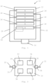
- Figure 1 shows a mattress system 10 comprising a mattress 12 and a control unit 14.
- the mattress comprises a first set of interconnected chambers 16 and second set of interconnected chambers 18.
- the first set of interconnected chambers 16 is connected to the control unit 14 by a connection tube 20, such that the control unit 14 may increase or decrease the pressure within the first set of interconnected chambers 16.
- the second set of interconnected chambers 18 is also connected to the control unit 14 by a connection tube 22, such that the control unit 14 may increase or decrease the pressure within the second set of interconnected chambers 18.
- the first set of interconnected chambers 16 and second set of interconnected chambers 18 may be arranged to be independently adjustable by the control unit 14 in an active mode, and increase or decrease in pressure in one set of interconnected chambers has no effect on the pressure within the other set of interconnected chambers.
- the first set of interconnected chambers 16 and second set of interconnected chambers 18 may be arranged to be in fluid communication in a passive mode, where air may pass between the first set of interconnected chambers 16 and second set of interconnected chambers 18.
- the change between the independent operation and fluid communication may be controlled by a switch, for example a solenoid switch (not shown) in the control unit 14.
- connection tube 20 and connection tube 22 are each joined to the control unit 14 by a connector valve 24, 26.
- Each connector valve 24, 26, comprises a pressure sensor 28, 30, the pressure sensors arranged to monitor the backpressure in the interconnected chambers.
- the mattress system 10 has a first, passive, mode, in which the control unit 14 monitors pressure changes within the plurality of interconnected chambers 16, 18, and a second, active, mode, in which the control unit 14 is used to adjust the pressure levels within the plurality of interconnected chambers 16, 18.
- the pressure sensor 28 is arranged such that when the mattress system is in the first, passive, mode, pressure changes within the first set of interconnected chambers are detected by the sensor 28.
- the pressure sensor 30 is arranged such that when the mattress system is in the first, passive, mode, pressure changes within the second set of interconnected chambers are detected by the sensor 30.
- the control unit 14 further comprises a pump unit 32.
- the pump unit 32 is activated by the control unit 14 when in the active mode, in order to increase or decrease the pressure within the plurality of interconnected chambers 16, 18.
- the control unit 14 is arranged to receive the sensor data obtained by the sensors 28, 30.
- the control unit 14 further comprises a processor 34, to which the control unit 14 sends the sensor data.
- the processor 34 analyses the sensor readings, and determines whether they fall within a first set of readings or second set of readings.
- the first set of readings are chosen such that they represent the patient moving a sufficient amount, both in frequency and type of movement, that the risk of pressure ulcers is low.
- the first set of readings may comprise the detection of three or more occurrences of pressure changes greater than 2mmHg over an hour long period.
- the second set of readings are chosen such that they represent the patient moving an insufficient amount, and the risk of pressure ulcers is high, for example the detection of two or fewer occurrences of pressure changes less than 2mmHg over an hour long period.
- the pumping function of the control unit 14 is either deactivated, or left inactive, thereby putting the mattress system in the first, passive, mode.
- control unit 14 In response to the processor 34 categorising the sensor readings in the second set, two possible responses are available depending on how the control unit 14 has been configured. If the control unit 14 has configured to "automatic" mode, the control unit 14 will automatically activate the pumping function of the pump unit 32, thereby putting the mattress system in the second, active mode. If the control unit 14 has been configured to "instruct” mode, the control unit 14 will activate an alarm signal via a communications module 36.
- the communications module 36 may be configured to emit an audible and/or visual alarm, or send a notification signal to a care provider, for example a mobile phone of a nurse, or to a centralised monitoring centre.
- the care provider may decide to initiate the second, active mode of the mattress system 10, for example by pressing a button on the control unit 14 if the care provider is present, or sending an activation signal to the communications module 36 should the care provider be in a remote location.
- the care provider may decide to override the alarm signal, and choose to leave the mattress system 10 in the first, passive, mode.
- the control unit 14 may be configured to automatically put the mattress system 10 into the second, active, mode after a predetermined period of time, for example 30 minutes after sending the alarm signal.
- the mattress system 10 further comprises a calibration mode, where the control unit 14 is configured to detect the approximate weight of a patient lying on the mattress 12.
- the control unit 14 may inflate the plurality of interconnected chambers to a first pressure, for example 30mmHg.
- the control unit 14 is then arranged to allow the deflation of the plurality of interconnected chambers to a second pressure, for example 6mmHg.
- the control unit is further arranged to monitor the deflation time from the first pressure to the second pressure.
- the deflation time is dependent on the weight of a patient, and the control unit includes a calibration table with a series of deflation times and associated patient weights. By comparison of the deflation time with the calibration table, the approximate weight of the patient may be determined.
- the control unit may adjust the threshold values for the pressure changes which indicate useful movement of a patient. For example, for a particularly light patient, the threshold pressure value may be reduced, and for a particularly heavy patient, the threshold pressure value may be increased. Therefore, the system may be automatically configured to provide the optimum patient monitoring without requiring any additional input from a user or healthcare professional.
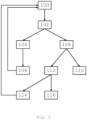
- FIG. 3 shows various processes the mattress system 10 may be configured to undertake. Initially, the sensors 28, 30 in the control unit 14 are arranged such that they monitor the pressure changes in the mattress 100. The processor 34 then analyses the pressure sensor readings 102. If the pressure sensor readings fall within a first set of readings 104, indicating that no action is required, the mattress system 10 remains in the passive mode 106. The process then returns to the monitoring stage 100.
- the mattress system is automatically switched to the active mode 110. If configured for "alert" operation, a notification is sent to a care provider, or an alarm is triggered at the pump unit 112. On receipt of the notification, or on noticing the alarm, the care provider may decide to leave the mattress system in passive mode 114, and the process returns to the monitoring stage 110. Alternatively, the care provider may decide to initiate the active mode of the mattress 116. If no response is received from the care provider within a certain time frame, the control unit 14 may assume that the care provider is unavailable and activate the active mode of the mattress system 116.
- FIG. 4 is an alternative flow diagram demonstrating how the mattress system may operate.
- the method is similar, with the addition of a calibration step at the beginning.
- a patient lies on a mattress, and the mattress system 10 enters the configuration mode 202.
- the control unit 14 of the mattress system 10 inflates the plurality of chambers 16, 18, to a first pressure, in this case 30mmHg, in step 204.
- the control unit 14 then allows the plurality of chambers 16, 18, to deflate to a second pressure, in this case 6mmHg, in step 206.
- the deflation time from the first pressure to the second pressure is monitored, and compared to a table of results stored in the control unit 14.
- the weight of the patient may be obtained.
- the method may further comprise calibrating the threshold pressure value which indicates a useful movement, in step 210.
- the method may then proceed to step 100, as described with reference to figure 3 , and carry on as described with reference to figure 3 .
- the invention may comprise one or more pressure sensor mats located underneath the mattress, and more particularly under one or more of the plurality of interconnected chambers.
- An example position of a pressure sensor mat 40 is shown in figure 1 .
- the one or more pressure mats may be configured to communicate sensor readings to the control unit via wired or wireless communication.
- the invention may comprise pressure sensors associated, and mechanically coupled, to the pump unit and pressure sensor pads located underneath the mattress.
- the processing unit may analyse the pressure sensor readings of both types of pressure sensor when determining whether to activate the active mattress mode.
- the invention may also comprise a control unit being retrofitted to an existing mattress, where the existing mattress comprises a plurality of interconnecting chambers.
- the control unit may comprise one or more fixing elements, for fixing the control unit in position relative to the mattress.
- the fixing elements may comprise one or more hooks which may be used to secure the control unit to a bed frame. Therefore, the control unit may be used to convert a conventional mattress to an active/passive mattress system as described above.
- control unit is preferably electrically powered, and via a mains power connection.
- control unit may be battery powered.
- the control unit may be programmable via a wired or wireless connection to a computer device.
- the control unit may be configured to send communications to a smart device, such as a mobile phone or tablet via a pairing process, for example Bluetooth communication.
- the control unit may comprise an input panel, for example a keyboard or touchscreen, into which a care provider may input information such as a mobile phone number.
- the input panel may be configured to present a care provider with a number of options relating to the set up of the control unit, for example whether the control unit was arranged to send an alert signal or enter the active mode automatically.
- the plurality of interconnecting chambers may comprise an air-retaining material, for example a foam section.
- the foam section may comprise cross-sectional profile. Foam present in different chambers of the plurality of interconnecting chambers may have different cross-sectional profiles.
Landscapes
- Health & Medical Sciences (AREA)
- Nursing (AREA)
- Life Sciences & Earth Sciences (AREA)
- Animal Behavior & Ethology (AREA)
- General Health & Medical Sciences (AREA)
- Public Health (AREA)
- Veterinary Medicine (AREA)
- Invalid Beds And Related Equipment (AREA)
- Mattresses And Other Support Structures For Chairs And Beds (AREA)
Claims (15)
- Matratzensystem (10), umfassend:eine Matratze (12), die mehrere miteinander verbundene Kammern (16, 18) umfasst;eine Steuereinheit (14);wobei die mehreren miteinander verbundenen Kammern (16, 18) mit der Steuereinheit (14) verbunden sind, wobei die Aktivierung der Steuereinheit (14) den Druck innerhalb der mehreren miteinander verbundenen Kammern (16, 18) erhöhen oder verringern kann;wobei die Steuereinheit (14) ein oder mehrere Sensoren (28, 30) umfasst, die so eingestellt sind, dass sie Druckänderungen innerhalb der mehreren miteinander verbundenen Kammern (16, 18) erfasst, und einen Prozessor (34), der so eingestellt ist, dass er die Druckänderungen analysiert, die durch den einen oder die mehreren Sensoren (28, 30) erfasst werden,wobei das Matratzensystem (10) konfiguriert ist für die Verwendung in:einem aktiven Modus, in dem die Steuereinheit (14) aktiviert ist, um den Druck innerhalb der mehreren miteinander verbundenen Kammern (16, 18) zu erhöhen oder zu verringern, undeinem passiven Modus, in dem die Steuereinheit (14) so eingestellt ist, dass sie Druckänderungen innerhalb der mehreren miteinander verbundenen Kammern (16, 18) überwacht;wobei das Matratzensystem (10) ferner umfasst:einen Kalibiermodus, in dem die Steuereinheit (14) so eingestellt ist, dass sie den Druck innerhalb der mehreren miteinander verbundenen Kammern (16, 18) auf einen ersten Druck erhöht, dann einen Luftverlust in den mehreren miteinander verbundenen Kammern (16, 18) auf einen zweiten Druck zulässt, wobei die Zeit, die für den Luftverlust vom ersten Druck zum zweiten Druck benötigt wird, überwacht und aufgezeichnet wird;dadurch gekennzeichnet, dass:der Prozessor (34) so eingestellt ist, dass er als Antwort auf einen ersten Satz Druckänderungen ein erstes Signal sendet, auf das hin das Matratzensystem (10) so eingestellt wird, dass es in den passiven Modus schaltet oder in diesem verbleibt, und so eingestellt ist, dass er als Antwort auf einen zweiten Satz Druckänderungen, der sich vom ersten Satz Druckänderungen unterscheidet, ein zweites Signal sendet, auf das hin das Matratzensystem (10) so eingestellt wird, dass es in den aktiven Modus schaltet; undder erste Satz Druckänderungen wenigstens teilweise basierend auf der Zeit ermittelt wird, die für den Luftverlust vom ersten Druck zum zweiten Druck benötigt wird und die ermittelt wird, wenn das Matratzensystem (10) sich im Kalibriermodus befindet.
- Matratzensystem wie in Anspruch 1 beansprucht, wobei der erste Satz Druckänderungen ein oder mehrere Druckänderungen umfasst, die einen Schwellenwert eine bestimmte Anzahl von Malen innerhalb eines bestimmten Zeitraums überschreiten.
- Matratzensystem wie in Anspruch 2 beansprucht, wobei der zweite Satz Druckänderungen Druckänderungen umfasst, die den Schwellenwert die bestimmte Anzahl von Malen innerhalb des bestimmten Zeitraums nicht überschreiten.
- Matratzensystem wie in einem vorhergehenden Anspruch beansprucht, wobei die Steuereinheit (14) einen Eingang und einen Ausgang umfasst, wobei der Eingang und der Ausgang mit den mehreren miteinander verbundenen Kammern (16, 18) verbunden sind, wobei ein Drucksensor (28, 30) mit einem oder mit beiden der Ein- und Ausgänge der Steuereinheit (14) verbunden ist.
- Matratzensystem wie in einem vorhergehenden Anspruch beansprucht, wobei ein oder mehrere Drucksensoren sich unter einer oder mehreren der mehreren miteinander verbundenen Kammern (16, 18) befinden.
- Matratzensystem wie in Anspruch 5 beansprucht, wobei der Drucksensor eine Drucksensormatte umfasst.
- Matratzensystem wie in einem vorhergehenden Anspruch beansprucht, wobei die Matratze (12) einen ersten Satz von miteinander verbundenen Kammern (16) und einen zweiten Satz von miteinander verbundenen Kammern (18) umfasst, wobei der Druck im ersten Satz von miteinander verbundenen Kammern (16) unabhängig vom Druck im zweiten Satz von miteinander verbundenen Kammern (18) einstellbar ist.
- Matratzensystem wie in einem der Ansprüche 1 bis 6 beansprucht, wobei die Matratze einen ersten Satz von miteinander verbundenen Kammern (16) und einen zweiten Satz von miteinander verbundenen Kammern (18) umfasst, wobei der erste Satz von miteinander verbundenen Kammern (16) umschaltbar ist zwischen unabhängig vom zweiten Satz von miteinander verbundenen Kammern (18) und in Fluidverbindung mit dem zweiten Satz von miteinander verbundenen Kammern (18),
wobei der Druck im ersten Satz von miteinander verbundenen Kammern (16) unabhängig vom Druck im zweiten Satz von miteinander verbundenen Kammern (18) einstellbar ist, wenn das Matratzensystem (10) sich im aktiven Modus befindet, und der erste Satz von miteinander verbundenen Kammern (16) sich in Fluidverbindung mit dem zweiten Satz von miteinander verbundenen Kammern (18) befindet, wenn es sich im passiven Modus befindet. - Verfahren zur Steuerung eines Matratzensystems (10), wobei das Verfahren die folgenden Schritte umfasst:
Bereitstellen eines Matratzensystems (10), wobei das Matratzensystem (10) mehrere miteinander verbundene Kammern (16, 18) und eine Steuereinheit (14) umfasst, wobei das Matratzensystem (10) besitzt:einen aktiven Modus, in dem die Steuereinheit (14) aktiviert ist, um den Druck innerhalb der mehreren miteinander verbundenen Kammern (16, 18) zu erhöhen oder zu verringern,einen passiven Modus, in dem die Steuereinheit (14) den Druck innerhalb der mehreren miteinander verbundenen Kammern (16, 18) nicht erhöht oder verringert, wobei die Steuereinheit (14) ferner ein oder mehrere Sensoren (28, 30) umfasst, die so eingestellt sind, dass sie Druckänderungen innerhalb der mehreren miteinander verbundenen Kammern (16, 18) erfasst, wenn die Steuereinheit (14) sich im passiven Modus befindet, undeinen Kalibiermodus, in dem die Steuereinheit (14) so konfiguriert ist, dass sie den Druck innerhalb der mehreren miteinander verbundenen Kammern (16, 18) auf einen ersten Druck erhöht und dann den Luftverlust in den mehreren miteinander verbundenen Kammern (16, 18) auf einen zweiten Druck zulässt, und eine Zeit überwacht, die für den Luftverlust vom ersten Druck zum zweiten Druck benötigt wird;Konfigurieren des Matratzensystems (10) in den Kalibiermodus und ermitteln der Zeit, die für den Luftverlust vom ersten Druck zum zweiten Druck benötigt wird;Ermitteln eines ersten Satzes Druckänderungen und eines zweiten, unterschiedlichen Satzes von Druckänderungen, basierend auf der Zeit, die für den Luftverlust vom ersten Druck zum zweiten Druck benötigt wird;Konfigurieren des Matratzensystems (10) in den passiven Modus,Überwachen der Druckänderungen in den mehreren miteinander verbundenen Kammern (16, 18) unter Verwendung der ein oder mehreren Sensoren (28, 30), und,wenn die ermittelten Druckänderungen in den ersten Satz Druckänderungen fallen, Erzeugen eines ersten Signals durch die Steuereinheit (14), welches die Steuereinheit (14) anweist, im passiven Modus zu verbleiben, und, wenn die ermittelten Druckänderungen in den zweiten Satz Druckänderungen fallen, Erzeugen eines zweiten Signals durch die Steuereinheit (14), welches sich vom ersten Signal unterscheidet. - Verfahren wie in Anspruch 9 beansprucht, wobei die Steuereinheit (14) die Luftverlustzeit zur Berechnung eines ungefähren Gewichts eines Patienten heranzieht.
- Verfahren wie in Anspruch 9 oder 10 beansprucht, wobei der zweite Satz Druckänderungen ausgewählt wird, um anzuzeigen, dass ein Bewegungsmuster eines Patienten ein Risiko für die Ausbildung von Dekubitalgeschwüren darstellt.
- Verfahren wie in Anspruch 11 beansprucht, wobei das zweite Signal die Steuereinheit (14) anweist, in den aktiven Modus zu schalten und damit zu beginnen, den Druck innerhalb der mehreren miteinander verbundenen Kammern (16, 18) zu ändern.
- Verfahren wie in Anspruch 11 beansprucht, wobei das zweite Signal bewirkt, dass die Steuereinheit (14) eine Warnmeldung ausgibt, die an einen Pflegedienstleister gesendet wird, wobei die Warnmeldung Anweisungen anfordert, ob das Matratzensystem (10) in den aktiven Modus schalten soll.
- Verfahren wie in Anspruch 13 beansprucht, wobei als Reaktion auf die Anweisungen vom Pflegedienstleister das Matratzensystem (10) in den aktiven Modus schaltet oder im passiven Modus verbleibt.
- Steuereinheit (14) für ein Matratzensystem (10) gemäß Anspruch 1, wobei die Steuereinheit (14) umfasst:einen Ausgang, wobei der Ausgang konfiguriert ist zur Verbindung mit mehreren miteinander verbundenen Kammern (16, 18), wobei der Ausgang ferner einen Sensor (28, 30) umfasst, der eingestellt ist, um Druckänderungen in den mehreren miteinander verbundenen Kammern (16, 18) zu erfassen, wenn der Ausgang mit den mehreren miteinander verbundenen Kammern (16, 18) verbunden ist, undeinen Prozessor (34), der so eingestellt ist, dass er die vom Sensor (28, 30) erfassten Druckänderungen analysiert;wobei die Steuereinheit (14) so konfiguriert ist, dass sie das Matratzensystem (10) betreibt in:einem aktiven Modus, in dem die Steuereinheit (14) aktiviert ist, um den Druck innerhalb der mehreren miteinander verbundenen Kammern (16, 18) zu erhöhen oder zu verringern,einem passiven Modus, in dem die Steuereinheit (14) so eingestellt ist, dass sie Druckänderungen innerhalb der mehreren miteinander verbundenen Kammern (16, 18) überwacht, undwobei die Steuereinheit (14) ferner so konfiguriert ist, dass sie das Matratzensystem (10) betreibt in:einem Kalibiermodus, in dem die Steuereinheit (14) so eingestellt ist, dass sie den Druck innerhalb der mehreren miteinander verbundenen Kammern (16, 18) auf einen ersten Druck erhöht, dann einen Luftverlust in den mehreren miteinander verbundenen Kammern (16, 18) auf einen zweiten Druck zulässt, wobei die Zeit, die für den Luftverlust vom ersten Druck zum zweiten Druck benötigt wird, überwacht und aufgezeichnet wird;dadurch gekennzeichnet, dass:der Prozessor (34) so eingestellt ist, dass er als Antwort auf einen ersten Satz Druckänderungen ein erstes Signal sendet, auf das hin das Matratzensystem (10) so eingestellt wird, dass es in den passiven Modus schaltet oder in diesem verbleibt, und so eingestellt ist, dass er als Antwort auf einen zweiten Satz Druckänderungen, der sich vom ersten Satz Druckänderungen unterscheidet, ein zweites Signal sendet, auf das hin das Matratzensystem (10) so eingestellt wird, dass es in den aktiven Modus schaltet; undder erste Satz Druckänderungen wenigstens teilweise basierend auf der Zeit ermittelt wird, die für den Luftverlust vom ersten Druck zum zweiten Druck benötigt wird und die ermittelt wird, wenn das Matratzensystem (10) sich im Kalibriermodus befindet.
Applications Claiming Priority (3)
| Application Number | Priority Date | Filing Date | Title |
|---|---|---|---|
| GBGB1702002.5A GB201702002D0 (en) | 2017-02-07 | 2017-02-07 | Mattress system |
| GB201719549A GB2559455B8 (en) | 2017-02-07 | 2017-11-24 | Mattress System |
| PCT/GB2018/050299 WO2018146458A1 (en) | 2017-02-07 | 2018-02-01 | Mattress system |
Publications (3)
| Publication Number | Publication Date |
|---|---|
| EP3579807A1 EP3579807A1 (de) | 2019-12-18 |
| EP3579807B1 true EP3579807B1 (de) | 2024-08-21 |
| EP3579807C0 EP3579807C0 (de) | 2024-08-21 |
Family
ID=58462343
Family Applications (1)
| Application Number | Title | Priority Date | Filing Date |
|---|---|---|---|
| EP18703840.1A Active EP3579807B1 (de) | 2017-02-07 | 2018-02-01 | Matratzensystem |
Country Status (3)
| Country | Link |
|---|---|
| EP (1) | EP3579807B1 (de) |
| GB (3) | GB201702002D0 (de) |
| WO (1) | WO2018146458A1 (de) |
Families Citing this family (2)
| Publication number | Priority date | Publication date | Assignee | Title |
|---|---|---|---|---|
| GB2521324B (en) | 2012-10-15 | 2020-03-25 | Kap Medical Inc | Patient support apparatus and method |
| CN116850527B (zh) * | 2023-08-17 | 2025-07-22 | 河北工业大学 | 配合半失能用户主动康复训练的气囊床垫控制方法及系统 |
Citations (1)
| Publication number | Priority date | Publication date | Assignee | Title |
|---|---|---|---|---|
| EP2735293A1 (de) * | 2012-11-27 | 2014-05-28 | MKS Innovatech S.r.l. | Vorrichtung mit aufblasbarer Matratze und Verfahren zum Unterstützen eines Patienten mit einer solchen Vorrichtung |
Family Cites Families (12)
| Publication number | Priority date | Publication date | Assignee | Title |
|---|---|---|---|---|
| US5020176A (en) * | 1989-10-20 | 1991-06-04 | Angel Echevarria Co., Inc. | Control system for fluid-filled beds |
| US5873137A (en) * | 1996-06-17 | 1999-02-23 | Medogar Technologies | Pnuematic mattress systems |
| US5963997A (en) * | 1997-03-24 | 1999-10-12 | Hagopian; Mark | Low air loss patient support system providing active feedback pressure sensing and correction capabilities for use as a bed mattress and a wheelchair seating system |
| JPH10313981A (ja) * | 1997-05-15 | 1998-12-02 | Aihou:Kk | エアーベッド |
| US7883478B2 (en) * | 2004-04-30 | 2011-02-08 | Hill-Rom Services, Inc. | Patient support having real time pressure control |
| DE102004041996A1 (de) * | 2004-08-31 | 2006-03-02 | Arno Friedrichs | Liegevorrichtung |
| US8087113B2 (en) * | 2005-05-12 | 2012-01-03 | Hunteigh Technology Limited | Inflatable support |
| WO2007008831A2 (en) * | 2005-07-08 | 2007-01-18 | Hill-Rom, Inc. | Control unit for patient support |
| FR2922439B1 (fr) * | 2007-10-18 | 2010-12-10 | Hill Rom Ind Sa | Procede de gonflage alterne d'un dispositif de support a cellules gonflables et dispositif pour sa mise en oeuvre |
| US8533879B1 (en) * | 2008-03-15 | 2013-09-17 | Stryker Corporation | Adaptive cushion method and apparatus for minimizing force concentrations on a human body |
| GB2492234B (en) * | 2011-06-23 | 2016-03-09 | Su Med Internat Uk Ltd | Improvements in and relating to mattresses |
| GB2492147B (en) * | 2011-06-23 | 2016-10-26 | Su-Med Int (Uk) Ltd | Improvements in and relating to mattresses |
-
2017
- 2017-02-07 GB GBGB1702002.5A patent/GB201702002D0/en not_active Ceased
- 2017-11-24 GB GB201919293A patent/GB2578537B8/en not_active Expired - Fee Related
- 2017-11-24 GB GB201719549A patent/GB2559455B8/en active Active
-
2018
- 2018-02-01 WO PCT/GB2018/050299 patent/WO2018146458A1/en not_active Ceased
- 2018-02-01 EP EP18703840.1A patent/EP3579807B1/de active Active
Patent Citations (1)
| Publication number | Priority date | Publication date | Assignee | Title |
|---|---|---|---|---|
| EP2735293A1 (de) * | 2012-11-27 | 2014-05-28 | MKS Innovatech S.r.l. | Vorrichtung mit aufblasbarer Matratze und Verfahren zum Unterstützen eines Patienten mit einer solchen Vorrichtung |
Also Published As
| Publication number | Publication date |
|---|---|
| GB201919293D0 (en) | 2020-02-05 |
| GB2578537A (en) | 2020-05-13 |
| GB2559455A (en) | 2018-08-08 |
| GB2559455B8 (en) | 2021-06-16 |
| GB2578537B8 (en) | 2021-06-16 |
| GB2559455B (en) | 2020-02-19 |
| GB201702002D0 (en) | 2017-03-22 |
| WO2018146458A1 (en) | 2018-08-16 |
| GB2578537B (en) | 2021-03-03 |
| EP3579807C0 (de) | 2024-08-21 |
| GB2578537A8 (en) | 2021-06-16 |
| GB2559455A8 (en) | 2021-06-16 |
| EP3579807A1 (de) | 2019-12-18 |
| GB201719549D0 (en) | 2018-01-10 |
Similar Documents
| Publication | Publication Date | Title |
|---|---|---|
| US20250031999A1 (en) | Exit detection system with compensation | |
| US7883478B2 (en) | Patient support having real time pressure control | |
| EP1906793B1 (de) | Drucksteuerung für ein krankenhausbett | |
| US7557718B2 (en) | Lack of patient movement monitor and method | |
| US6058537A (en) | Pressure control apparatus for air mattresses | |
| US9504416B2 (en) | Smart seat monitoring system | |
| JP4685330B2 (ja) | 膨張可能な支持体 | |
| EP2892489B1 (de) | Aufblasbare matratze und steuerungsverfahren | |
| JP2003000553A (ja) | 患者検知装置 | |
| EP1374822A1 (de) | Bodennäherungssensor | |
| EP2281540A2 (de) | Auf der Gesundheit des Patienten basierende Liegevorrichtungskonfiguration | |
| US20090084609A1 (en) | Mattress seat force sensing method | |
| CA2346207A1 (en) | Force optimization surface apparatus and method | |
| WO2002015835A1 (en) | Inflatable mattress system and method of use thereof | |
| EP3579807B1 (de) | Matratzensystem | |
| US8419660B1 (en) | Patient monitoring system | |
| US10347110B1 (en) | Reclining mechanism or bed with built-in pressure alarm and dynamic therapeutic adjustment capabilities | |
| AU2003209483B2 (en) | Inflatable support | |
| GB2568875A (en) | Mattress and pump arrangement | |
| US20250160685A1 (en) | Pressure based presence monitoring systems and methods of monitoring presence based on pressure | |
| JP7277915B2 (ja) | システム、及び上げ下げ装置 | |
| GB2636796A (en) | Pressure pump apparatus | |
| CN111035516A (zh) | 医疗气垫床的智能控制系统 | |
| GB2570280A (en) | Monitoring apparatus | |
| GB2594135A (en) | Seat pad system |
Legal Events
| Date | Code | Title | Description |
|---|---|---|---|
| STAA | Information on the status of an ep patent application or granted ep patent |
Free format text: STATUS: UNKNOWN |
|
| STAA | Information on the status of an ep patent application or granted ep patent |
Free format text: STATUS: THE INTERNATIONAL PUBLICATION HAS BEEN MADE |
|
| PUAI | Public reference made under article 153(3) epc to a published international application that has entered the european phase |
Free format text: ORIGINAL CODE: 0009012 |
|
| STAA | Information on the status of an ep patent application or granted ep patent |
Free format text: STATUS: REQUEST FOR EXAMINATION WAS MADE |
|
| 17P | Request for examination filed |
Effective date: 20190808 |
|
| AK | Designated contracting states |
Kind code of ref document: A1 Designated state(s): AL AT BE BG CH CY CZ DE DK EE ES FI FR GB GR HR HU IE IS IT LI LT LU LV MC MK MT NL NO PL PT RO RS SE SI SK SM TR |
|
| AX | Request for extension of the european patent |
Extension state: BA ME |
|
| DAV | Request for validation of the european patent (deleted) | ||
| DAX | Request for extension of the european patent (deleted) | ||
| RIN1 | Information on inventor provided before grant (corrected) |
Inventor name: LEWIS, JON Inventor name: EWART, GRAHAM |
|
| STAA | Information on the status of an ep patent application or granted ep patent |
Free format text: STATUS: EXAMINATION IS IN PROGRESS |
|
| 17Q | First examination report despatched |
Effective date: 20220816 |
|
| GRAP | Despatch of communication of intention to grant a patent |
Free format text: ORIGINAL CODE: EPIDOSNIGR1 |
|
| STAA | Information on the status of an ep patent application or granted ep patent |
Free format text: STATUS: GRANT OF PATENT IS INTENDED |
|
| INTG | Intention to grant announced |
Effective date: 20240319 |
|
| GRAS | Grant fee paid |
Free format text: ORIGINAL CODE: EPIDOSNIGR3 |
|
| GRAA | (expected) grant |
Free format text: ORIGINAL CODE: 0009210 |
|
| STAA | Information on the status of an ep patent application or granted ep patent |
Free format text: STATUS: THE PATENT HAS BEEN GRANTED |
|
| AK | Designated contracting states |
Kind code of ref document: B1 Designated state(s): AL AT BE BG CH CY CZ DE DK EE ES FI FR GB GR HR HU IE IS IT LI LT LU LV MC MK MT NL NO PL PT RO RS SE SI SK SM TR |
|
| REG | Reference to a national code |
Ref country code: GB Ref legal event code: FG4D |
|
| REG | Reference to a national code |
Ref country code: CH Ref legal event code: EP |
|
| REG | Reference to a national code |
Ref country code: DE Ref legal event code: R096 Ref document number: 602018073313 Country of ref document: DE |
|
| REG | Reference to a national code |
Ref country code: IE Ref legal event code: FG4D |
|
| U01 | Request for unitary effect filed |
Effective date: 20240823 |
|
| U07 | Unitary effect registered |
Designated state(s): AT BE BG DE DK EE FI FR IT LT LU LV MT NL PT RO SE SI Effective date: 20240903 |
|
| PG25 | Lapsed in a contracting state [announced via postgrant information from national office to epo] |
Ref country code: NO Free format text: LAPSE BECAUSE OF FAILURE TO SUBMIT A TRANSLATION OF THE DESCRIPTION OR TO PAY THE FEE WITHIN THE PRESCRIBED TIME-LIMIT Effective date: 20241121 |
|
| PG25 | Lapsed in a contracting state [announced via postgrant information from national office to epo] |
Ref country code: PL Free format text: LAPSE BECAUSE OF FAILURE TO SUBMIT A TRANSLATION OF THE DESCRIPTION OR TO PAY THE FEE WITHIN THE PRESCRIBED TIME-LIMIT Effective date: 20240821 Ref country code: GR Free format text: LAPSE BECAUSE OF FAILURE TO SUBMIT A TRANSLATION OF THE DESCRIPTION OR TO PAY THE FEE WITHIN THE PRESCRIBED TIME-LIMIT Effective date: 20241122 |
|
| PG25 | Lapsed in a contracting state [announced via postgrant information from national office to epo] |
Ref country code: IS Free format text: LAPSE BECAUSE OF FAILURE TO SUBMIT A TRANSLATION OF THE DESCRIPTION OR TO PAY THE FEE WITHIN THE PRESCRIBED TIME-LIMIT Effective date: 20241221 |
|
| PG25 | Lapsed in a contracting state [announced via postgrant information from national office to epo] |
Ref country code: HR Free format text: LAPSE BECAUSE OF FAILURE TO SUBMIT A TRANSLATION OF THE DESCRIPTION OR TO PAY THE FEE WITHIN THE PRESCRIBED TIME-LIMIT Effective date: 20240821 |
|
| PG25 | Lapsed in a contracting state [announced via postgrant information from national office to epo] |
Ref country code: ES Free format text: LAPSE BECAUSE OF FAILURE TO SUBMIT A TRANSLATION OF THE DESCRIPTION OR TO PAY THE FEE WITHIN THE PRESCRIBED TIME-LIMIT Effective date: 20240821 Ref country code: RS Free format text: LAPSE BECAUSE OF FAILURE TO SUBMIT A TRANSLATION OF THE DESCRIPTION OR TO PAY THE FEE WITHIN THE PRESCRIBED TIME-LIMIT Effective date: 20241121 |
|
| PG25 | Lapsed in a contracting state [announced via postgrant information from national office to epo] |
Ref country code: RS Free format text: LAPSE BECAUSE OF FAILURE TO SUBMIT A TRANSLATION OF THE DESCRIPTION OR TO PAY THE FEE WITHIN THE PRESCRIBED TIME-LIMIT Effective date: 20241121 Ref country code: PL Free format text: LAPSE BECAUSE OF FAILURE TO SUBMIT A TRANSLATION OF THE DESCRIPTION OR TO PAY THE FEE WITHIN THE PRESCRIBED TIME-LIMIT Effective date: 20240821 Ref country code: NO Free format text: LAPSE BECAUSE OF FAILURE TO SUBMIT A TRANSLATION OF THE DESCRIPTION OR TO PAY THE FEE WITHIN THE PRESCRIBED TIME-LIMIT Effective date: 20241121 Ref country code: IS Free format text: LAPSE BECAUSE OF FAILURE TO SUBMIT A TRANSLATION OF THE DESCRIPTION OR TO PAY THE FEE WITHIN THE PRESCRIBED TIME-LIMIT Effective date: 20241221 Ref country code: HR Free format text: LAPSE BECAUSE OF FAILURE TO SUBMIT A TRANSLATION OF THE DESCRIPTION OR TO PAY THE FEE WITHIN THE PRESCRIBED TIME-LIMIT Effective date: 20240821 Ref country code: GR Free format text: LAPSE BECAUSE OF FAILURE TO SUBMIT A TRANSLATION OF THE DESCRIPTION OR TO PAY THE FEE WITHIN THE PRESCRIBED TIME-LIMIT Effective date: 20241122 Ref country code: ES Free format text: LAPSE BECAUSE OF FAILURE TO SUBMIT A TRANSLATION OF THE DESCRIPTION OR TO PAY THE FEE WITHIN THE PRESCRIBED TIME-LIMIT Effective date: 20240821 |
|
| U20 | Renewal fee for the european patent with unitary effect paid |
Year of fee payment: 8 Effective date: 20250107 |
|
| PG25 | Lapsed in a contracting state [announced via postgrant information from national office to epo] |
Ref country code: SM Free format text: LAPSE BECAUSE OF FAILURE TO SUBMIT A TRANSLATION OF THE DESCRIPTION OR TO PAY THE FEE WITHIN THE PRESCRIBED TIME-LIMIT Effective date: 20240821 |
|
| PG25 | Lapsed in a contracting state [announced via postgrant information from national office to epo] |
Ref country code: CZ Free format text: LAPSE BECAUSE OF FAILURE TO SUBMIT A TRANSLATION OF THE DESCRIPTION OR TO PAY THE FEE WITHIN THE PRESCRIBED TIME-LIMIT Effective date: 20240821 |
|
| PG25 | Lapsed in a contracting state [announced via postgrant information from national office to epo] |
Ref country code: SK Free format text: LAPSE BECAUSE OF FAILURE TO SUBMIT A TRANSLATION OF THE DESCRIPTION OR TO PAY THE FEE WITHIN THE PRESCRIBED TIME-LIMIT Effective date: 20240821 |
|
| PLBE | No opposition filed within time limit |
Free format text: ORIGINAL CODE: 0009261 |
|
| STAA | Information on the status of an ep patent application or granted ep patent |
Free format text: STATUS: NO OPPOSITION FILED WITHIN TIME LIMIT |
|
| 26N | No opposition filed |
Effective date: 20250522 |
|
| PG25 | Lapsed in a contracting state [announced via postgrant information from national office to epo] |
Ref country code: MC Free format text: LAPSE BECAUSE OF FAILURE TO SUBMIT A TRANSLATION OF THE DESCRIPTION OR TO PAY THE FEE WITHIN THE PRESCRIBED TIME-LIMIT Effective date: 20240821 |
|
| REG | Reference to a national code |
Ref country code: CH Ref legal event code: PL |
|
| PG25 | Lapsed in a contracting state [announced via postgrant information from national office to epo] |
Ref country code: CH Free format text: LAPSE BECAUSE OF NON-PAYMENT OF DUE FEES Effective date: 20250228 |
|
| PGFP | Annual fee paid to national office [announced via postgrant information from national office to epo] |
Ref country code: GB Payment date: 20251211 Year of fee payment: 9 |
|
| PG25 | Lapsed in a contracting state [announced via postgrant information from national office to epo] |
Ref country code: IE Free format text: LAPSE BECAUSE OF NON-PAYMENT OF DUE FEES Effective date: 20250201 |
|
| U20 | Renewal fee for the european patent with unitary effect paid |
Year of fee payment: 9 Effective date: 20260106 |