EP3579773B1 - Stabilizer holder and inserter tool - Google Patents
Stabilizer holder and inserter tool Download PDFInfo
- Publication number
- EP3579773B1 EP3579773B1 EP18707802.7A EP18707802A EP3579773B1 EP 3579773 B1 EP3579773 B1 EP 3579773B1 EP 18707802 A EP18707802 A EP 18707802A EP 3579773 B1 EP3579773 B1 EP 3579773B1
- Authority
- EP
- European Patent Office
- Prior art keywords
- head
- stabilizer
- driver
- handle
- bore
- Prior art date
- Legal status (The legal status is an assumption and is not a legal conclusion. Google has not performed a legal analysis and makes no representation as to the accuracy of the status listed.)
- Active
Links
Images



Classifications
-
- A—HUMAN NECESSITIES
- A61—MEDICAL OR VETERINARY SCIENCE; HYGIENE
- A61B—DIAGNOSIS; SURGERY; IDENTIFICATION
- A61B17/00—Surgical instruments, devices or methods
- A61B17/56—Surgical instruments or methods for treatment of bones or joints; Devices specially adapted therefor
- A61B17/58—Surgical instruments or methods for treatment of bones or joints; Devices specially adapted therefor for osteosynthesis, e.g. bone plates, screws or setting implements
- A61B17/68—Internal fixation devices, including fasteners and spinal fixators, even if a part thereof projects from the skin
- A61B17/80—Cortical plates, i.e. bone plates; Instruments for holding or positioning cortical plates, or for compressing bones attached to cortical plates
- A61B17/8061—Cortical plates, i.e. bone plates; Instruments for holding or positioning cortical plates, or for compressing bones attached to cortical plates specially adapted for particular bones
- A61B17/8076—Cortical plates, i.e. bone plates; Instruments for holding or positioning cortical plates, or for compressing bones attached to cortical plates specially adapted for particular bones for the ribs or the sternum
-
- A—HUMAN NECESSITIES
- A61—MEDICAL OR VETERINARY SCIENCE; HYGIENE
- A61B—DIAGNOSIS; SURGERY; IDENTIFICATION
- A61B17/00—Surgical instruments, devices or methods
- A61B17/56—Surgical instruments or methods for treatment of bones or joints; Devices specially adapted therefor
- A61B17/58—Surgical instruments or methods for treatment of bones or joints; Devices specially adapted therefor for osteosynthesis, e.g. bone plates, screws or setting implements
- A61B17/68—Internal fixation devices, including fasteners and spinal fixators, even if a part thereof projects from the skin
- A61B17/80—Cortical plates, i.e. bone plates; Instruments for holding or positioning cortical plates, or for compressing bones attached to cortical plates
- A61B17/8004—Cortical plates, i.e. bone plates; Instruments for holding or positioning cortical plates, or for compressing bones attached to cortical plates with means for distracting or compressing the bone or bones
- A61B17/8019—Cortical plates, i.e. bone plates; Instruments for holding or positioning cortical plates, or for compressing bones attached to cortical plates with means for distracting or compressing the bone or bones where the means are a separate tool rather than being part of the plate
-
- A—HUMAN NECESSITIES
- A61—MEDICAL OR VETERINARY SCIENCE; HYGIENE
- A61B—DIAGNOSIS; SURGERY; IDENTIFICATION
- A61B17/00—Surgical instruments, devices or methods
- A61B17/56—Surgical instruments or methods for treatment of bones or joints; Devices specially adapted therefor
- A61B17/58—Surgical instruments or methods for treatment of bones or joints; Devices specially adapted therefor for osteosynthesis, e.g. bone plates, screws or setting implements
- A61B17/68—Internal fixation devices, including fasteners and spinal fixators, even if a part thereof projects from the skin
- A61B17/80—Cortical plates, i.e. bone plates; Instruments for holding or positioning cortical plates, or for compressing bones attached to cortical plates
- A61B17/808—Instruments for holding or positioning bone plates, or for adjusting screw-to-plate locking mechanisms
-
- A—HUMAN NECESSITIES
- A61—MEDICAL OR VETERINARY SCIENCE; HYGIENE
- A61B—DIAGNOSIS; SURGERY; IDENTIFICATION
- A61B17/00—Surgical instruments, devices or methods
- A61B17/56—Surgical instruments or methods for treatment of bones or joints; Devices specially adapted therefor
- A61B17/58—Surgical instruments or methods for treatment of bones or joints; Devices specially adapted therefor for osteosynthesis, e.g. bone plates, screws or setting implements
- A61B17/88—Osteosynthesis instruments; Methods or means for implanting or extracting internal or external fixation devices
- A61B17/8875—Screwdrivers, spanners or wrenches
-
- A—HUMAN NECESSITIES
- A61—MEDICAL OR VETERINARY SCIENCE; HYGIENE
- A61F—FILTERS IMPLANTABLE INTO BLOOD VESSELS; PROSTHESES; DEVICES PROVIDING PATENCY TO, OR PREVENTING COLLAPSING OF, TUBULAR STRUCTURES OF THE BODY, e.g. STENTS; ORTHOPAEDIC, NURSING OR CONTRACEPTIVE DEVICES; FOMENTATION; TREATMENT OR PROTECTION OF EYES OR EARS; BANDAGES, DRESSINGS OR ABSORBENT PADS; FIRST-AID KITS
- A61F2/00—Filters implantable into blood vessels; Prostheses, i.e. artificial substitutes or replacements for parts of the body; Appliances for connecting them with the body; Devices providing patency to, or preventing collapsing of, tubular structures of the body, e.g. stents
- A61F2/02—Prostheses implantable into the body
- A61F2/28—Bones
-
- A—HUMAN NECESSITIES
- A61—MEDICAL OR VETERINARY SCIENCE; HYGIENE
- A61F—FILTERS IMPLANTABLE INTO BLOOD VESSELS; PROSTHESES; DEVICES PROVIDING PATENCY TO, OR PREVENTING COLLAPSING OF, TUBULAR STRUCTURES OF THE BODY, e.g. STENTS; ORTHOPAEDIC, NURSING OR CONTRACEPTIVE DEVICES; FOMENTATION; TREATMENT OR PROTECTION OF EYES OR EARS; BANDAGES, DRESSINGS OR ABSORBENT PADS; FIRST-AID KITS
- A61F2/00—Filters implantable into blood vessels; Prostheses, i.e. artificial substitutes or replacements for parts of the body; Appliances for connecting them with the body; Devices providing patency to, or preventing collapsing of, tubular structures of the body, e.g. stents
- A61F2/02—Prostheses implantable into the body
- A61F2/30—Joints
- A61F2002/30001—Additional features of subject-matter classified in A61F2/28, A61F2/30 and subgroups thereof
- A61F2002/30316—The prosthesis having different structural features at different locations within the same prosthesis; Connections between prosthetic parts; Special structural features of bone or joint prostheses not otherwise provided for
- A61F2002/30329—Connections or couplings between prosthetic parts, e.g. between modular parts; Connecting elements
- A61F2002/30476—Connections or couplings between prosthetic parts, e.g. between modular parts; Connecting elements locked by an additional locking mechanism
- A61F2002/30482—Connections or couplings between prosthetic parts, e.g. between modular parts; Connecting elements locked by an additional locking mechanism using a locking cam
-
- A—HUMAN NECESSITIES
- A61—MEDICAL OR VETERINARY SCIENCE; HYGIENE
- A61F—FILTERS IMPLANTABLE INTO BLOOD VESSELS; PROSTHESES; DEVICES PROVIDING PATENCY TO, OR PREVENTING COLLAPSING OF, TUBULAR STRUCTURES OF THE BODY, e.g. STENTS; ORTHOPAEDIC, NURSING OR CONTRACEPTIVE DEVICES; FOMENTATION; TREATMENT OR PROTECTION OF EYES OR EARS; BANDAGES, DRESSINGS OR ABSORBENT PADS; FIRST-AID KITS
- A61F2/00—Filters implantable into blood vessels; Prostheses, i.e. artificial substitutes or replacements for parts of the body; Appliances for connecting them with the body; Devices providing patency to, or preventing collapsing of, tubular structures of the body, e.g. stents
- A61F2/02—Prostheses implantable into the body
- A61F2/30—Joints
- A61F2/46—Special tools for implanting artificial joints
- A61F2/4603—Special tools for implanting artificial joints for insertion or extraction of endoprosthetic joints or of accessories thereof
- A61F2002/4622—Special tools for implanting artificial joints for insertion or extraction of endoprosthetic joints or of accessories thereof having the shape of a forceps or a clamp
Definitions
- Pectus excavatum and pectus carinatum are conditions affecting a human rib cage which can result from a congenital disorder or deformity.
- physicians install hardware into a patient's ribcage to reshape the ribcage.
- current hardware solutions may be difficult to secure to a patient.
- hardware installed on the ribcage may be difficult for a physician to reach and/or secure.
- a pectus bar stabilizer insertion tool of the type claimed is known from the document EP 1 721 580 A1 .
- a common corrective procedure includes securing a pectus bar to a patient's rib cage to reshape and stabilize the rib cage.
- This procedure can include the steps of: creating opposing incisions on each side of a patient's rib cage; inserting a curved pectus bar into one of the incisions; weaving the pectus bar through one or more ribs; flipping the pectus bar; securing the pectus bar to the rib cage; securing one or more stabilizers to the pectus bar; securing the one or more stabilizers to the rib cage; and, closing the incisions.
- incisions are located on an outer (lateral) portion of the rib cage for aesthetic purposes.
- stabilizers may be difficult for a physician to position on the pectus bar and the stabilizers may be difficult for a physician to secure to the pectus bar.
- the inventors have recognized, among other things, that a stabilizer tool can be used to secure a stabilizer to the tool, place the stabilizer on the pectus bar, and engage a lock of the stabilizer to secure the stabilizer to the pectus bar.
- the present application relates to devices and systems for pectus correction procedures.
- the present application discloses an assembly for coupling a pectus bar and stabilizers to a rib cage of a patient to correct pectus excavatum and pectus carinatum.
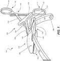
- FIG. 1 illustrates an isometric view of pectus bar assembly 100, which can include pectus bar 102, stabilizer 104, and stabilizer tool 106.
- Pectus bar 102 can include bar bores 108 (only one shown in FIG. 1 ).
- Stabilizer 104 can include first portion 110 and second portion 112.
- Stabilizer tool 106 can include first handle 114, second handle 116, first head 118, second head 120, first arm 122, second arm 124, and locking shaft 126.
- Pectus bar 102 can be a rigid or semi-rigid bar constructed of materials such as metals and plastics. Pectus bar 102 can have an elongate body forming a curve, such as a c-shape, in some examples. Bar bores 108 can be disposed near the terminations of pectus bar 102 and can be configured to receive fasteners, such as bone screws or sutures, to secure pectus bar 102 to ribs and/or soft tissues (such as muscles and cartilage) of a patient.
- fasteners such as bone screws or sutures
- Stabilizer 104 can be a rigid or semi-rigid component constructed of materials such as metals and plastics. Stabilizer 104 can be configured to engage and secure to pectus bar 102 anywhere along the length of pectus bar 102. Stabilizer 104 can also include bores (discussed later) that can be used to secure stabilizer 104 to ribs and/or soft tissues of the patient. Stabilizer 104 can also include a locking mechanism (shown and discussed below) that can be used to secure stabilizer 104 to pectus bar 102. First portion (or first side) 110 of stabilizer 104 can be opposite second portion (or second side) 112.
- First handle 114 of stabilizer tool 106 can be coupled to a first end of first arm 122 and first head 118 can be coupled to a second end of first arm 122.
- second handle 116 can be coupled to a first end of second arm 124 and second head 120 can be coupled to a second end of second arm 124.
- First arm 122 and second arm 124 can be pivotably coupled between first and second handles 114 and 116 and first and second heads 118 and 120, respectively.
- a procedure to correct pectus excavatum or pectus carinatum can include creating opposing incisions on each side of a patient's rib cage and inserting pectus bar 102 into one of the incisions.
- Pectus bar 102 can then be weaved through one or more ribs of the patient and flipped into a final position.
- stabilizers 104 can be inserted into the incisions and secured to pectus bar 102 and to the rib cage of the patient before final preparations are made and incisions are closed.
- a physician can position stabilizers 104 along the length of the bar as desired.
- stabilizer tool 106 can be used to secure stabilizer 104 to first portion 118 of stabilizer tool 106. Stabilizer 104 and stabilizer tool can then be inserted into an incision and a physician can use first handle 114 and second handle 116 to position stabilizer 104 on pectus bar 102 when first handle 114 and second handle 116 are in an either an open or closed position, as stabilizer 104 is secured to first head 118.
- first handle 114 and second handle 116 can be moved to a closed position, temporarily securing stabilizer 104 to pectus bar 102.
- the physician can rotate locking shaft 126 to operate the locking mechanism of stabilizer 104, locking stabilizer 104 to pectus bar 102 in the desired position.
- Stabilizer tool 106 thus enables a physician to place and secure a stabilizer on a pectus bar in a location relative to an incision that may otherwise be difficult to reach. Stabilizer 106 therefore can increase procedural efficiency, which can save time and cost.
- the details of the components of pectus bar assembly 100 shown in FIG. 1 are discussed in further detail below.
- stabilizer 104 can include recessed portion 128.
- Stabilizer tool 106 can include ratchet lock 130.
- First handle 114 can include finger hole 132 and second handle 116 can include finger hole 134.
- First head 118 can include driver pin bore 136.
- Locking shaft 126 can include locking handle 138.
- Recessed portion 128 can be a recess that is open at second portion 112 of stabilizer 104. Recessed portion 128 can be sized and shaped to receive pectus bar 102. In some other examples, recessed portion 128 can be open to first portion 110. A locking mechanism (discussed below in FIG. 2 ) can engage pectus bar 102 at recessed portion 128 to lock stabilizer 104 to pectus bar 102.
- Ratchet lock 130 can connect to first arm 122 and second arm 124 proximate first handle 114 and second handle 116, respectively. In operation of some examples, ratchet lock 130 can temporarily fix the position of first handle 114 relative to second handle 116 and therefore first head 118 relative to second head 120, for example in a closed position. Ratchet lock 130 can be released so that first handle 114 and second handle 116 can be moved between open and closed positions.
- First head 118 can include driver pin bore 136, which can be used to secure a driver within first head 118, as discussed further below.
- Locking shaft 126 can include locking handle 138, which can be used to apply a torque to locking shaft 126 in either rotational direction to operate the driver within first head 118, as described further below.
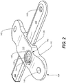
- FIG. 2 illustrates an isometric view of pectus bar 102 and stabilizer 104 of pectus bar assembly 100.
- Pectus bar 102 can include bar bores 108 (one shown in FIG. 2 ).
- Stabilizer 104 can include first portion 110, second portion 112 (not clearly visible in FIG. 2 ), recessed portion 128, stabilizer bores 140 and 142, and lock 143, which can include locking cam 144, cam bore 146, and tool engagement 148.
- FIG. 1 The components illustrated in FIG. 1 can be connected and can operate consistently with FIG. 1 ; however, FIG. 2 shows additional details of pectus bar 102 and stabilizer 104.
- FIG.2 shows stabilizer bores 142, which can be used to secure stabilizer 104 to bones, such as ribs, or soft tissues of a patient.
- Stabilizer bores 142 can be configured to receive fasteners, such as bone screws or sutures, in some examples.
- FIG. 2 also shows lock 143 of stabilizer 104, which can be a lock that is operable to secure stabilizer 104 to pectus bar 102 at recessed portion 128.
- cam bore 146 can be a bore extending from first portion 110 into stabilizer 104 and intersecting recessed portion 128.
- Cam bore 146 can include a captivated or integral slot that engages an integral tab of locking cam 144.
- Cam 144 can be a rotatable member configured to receive a driver at tool engagement 148.
- Tool engagement 148 can be configured to receive many types of drivers, such as slotted, cross-recess, hex, star, and the like.
- Cam 144 can include a tab engageable with bore 146, and can include a portion that engages pectus bar 102 to secure stabilizer 104 thereto. In some examples the tab and its engagement with bore 146 can prevent passive rotation of cam 144 and/or unlocking.
- stabilizer 104 can be placed and positioned on pectus bar 102 so that recessed portion 128 engages pectus bar 102.
- a driver such as a driver of stabilizer tool 106, as described below, can be inserted into tool engagement 148 and the driver can be rotated (for example in a clock-wise direction) to rotate locking cam 144 to lock against bore 146 and lock stabilizer 104 to pectus bar 102.
- This process can be reversed by rotating the driver in the opposite direction (for example, in a counter-clock-wise direction) to rotate locking cam 144, which can disengage locking cam 144 from locking bore 146 and pectus bar 102, so that stabilizer 104 can be removed from pectus bar 102 or can be repositioned relative to pectus bar 102.
- FIG. 2 shows only one type of locking cam and locking bore, stabilizer tool 106 can be used to drive many types of cams or fasteners.
- FIG. 3 illustrates an isometric view of a portion of stabilizer tool 106, which can include first head 118, first arm 122, and locking shaft 126.
- First head 118 can include driver pin bore 136, driver pin 150, shaft pin bore 152, snap fitting 154, driver 156, driver bore 158, and contouring 160.
- Driver 156 can include driver gear 162 (including teeth 164) and driver bit 166.
- Snap fitting 154 can include projections 168.
- orientation indicators Left and Right The components of FIG. 3 can connect and operate consistently with the components of FIGS. 1 and 2 ; however, FIG. 3 shows additional details of stabilizer tool 106.
- First arm 122 can connect to a right portion of first head 118 and locking shaft 126 can enter first head 118 at a left portion of first head 118.
- Locking shaft 126 can terminate within the left portion of first head 118, and can engage driver 156 within first head 118, as described further below.
- Driver pin 150 can be a pin, having a shape such as a cylinder, or other prismatic shape, and can be comprised of a rigid material, such as plastics, metals, and the like.
- Driver pin 150 can extend through first head 118, passing through driver pin bore 136 at a medial location of first head 118 (between left and right portions of first head 118).
- Driver pin bore 136 can pass over driver 156, so that driver pin 150 can engage driver 156, restricting axial motion of driver 156, while driver bore restricts motion of driver 156 in other directions.
- Shaft pin bore 152 can be a bore extending through the left portion of first head 118, proximate a termination of locking shaft 126 (as discussed further below).
- Snap fitting 154 extends from a surface of a right portion of first head 118 (generally towards second head 120 of FIG. 1 ). Though only one snap fitting is shown in FIG. 3 , more snap fittings, such as 1, 3, 4, 5, 10, and the like can be used. Snap fitting 154 includes two prongs, each having a projection 164 extending radially from each prong of snap fitting 154. Projections 168 can have a radius or diameter that is larger than that of a portion of the prongs connecting to first head 118.
- the prongs of snap fitting 154 are shown as being separated by a gap or slot, so that any force transverse to an axis of the snap fitting can cause one or both of the prongs to breach the gap, reducing the total diameter of snap fitting 154.
- snap fitting 154 can be inserted into a bore having a diameter smaller than that of projections 168 when snap fitting 154 is uncompressed. Projections 168 can expand to their normal diameter when projections 168 clear the bore, such as one of stabilizer bores 140 and 142 of FIG. 2 .
- snap fitting can disengage from a bore.
- Driver 156 can be disposed in a bore of first head 118, such as driver bore 158.
- Driver bore 158 can be circular in some examples, and can be of other shapes, such as octagonal, in other examples.
- Driver bore 158 can be sized to allow driver 156 to rotate within driver bore 158 without impeding the rotation of driver 156, while limiting substantial non-rotational movement of driver 156 relative to driver bore 158.
- Driver 156 can include driver gear 162, which can be a parallel axis gear, such as a spur gear, in some examples.
- Driver gear 162 can interface with a gear of locking shaft 126 at teeth 164 of driver gear 162, as shown in FIG. 5 below.
- Driver bit 166 can extend from a non-geared surface of driver gear 162 and can protrude from driver bore. The interaction between driver gear 162 and locking shaft 126 is discussed below in further detail in FIG. 5 .
- First head 118 can include head contouring 160, which can be a perimeter wall that is shaped to receive, or interface with, a stabilizer, such as stabilizer 104 of FIGS. 1 and 2 .
- Contouring 160 can be designed so that stabilizer 104 nests within first head 118 to limit movement of stabilizer 104 relative to first head 118 when stabilizer 104 is secured by snap fitting 154 and/or driver 156, as discussed further below.
- snap fitting 154 can be used to secure a stabilizer, such as stabilizer 104 of FIGS. 1 and 2 , to first head 118. That is, snap fitting 154 of first head 118 can be aligned with a bore of stabilizer 104, such as bores 140 or 142 of FIG. 2 . A force can then be applied to first head 118 (for example using first handle 114) and stabilizer 104 so that the walls or edges of the bore apply a force to projections 168, compressing the prongs of snap fitting 154, reducing the diameter of snap fitting 154, and allowing snap fitting 154 to enter the bore. When projections 168 have passed through the bore, projections 168 can expand, securing stabilizer 104 to stabilizer tool 106. In this position, stabilizer 104 can be nested within contouring 160 of head 118, further securing stabilizer 104 to first head 118.
- stabilizer tool 106 can be used to position stabilizer 104 on pectus bar 102.
- stabilizer 104 can be placed on pectus bar 102 before securing stabilizer 104 to stabilizer tool 106.
- stabilizer tool 106 can be closed using first handle 114 and second handle 116, securing stabilizer 104 to pectus bar 102, without locking the position of stabilizer 104 relative to pectus bar 102.
- Stabilizer 104 can then be positioned at any desired location on pectus bar 102 without losing an interface between stabilizer 104 and pectus bar 102.
- driver 156 When stabilizer tool 106 is in a closed position, driver 156, and more specifically, driver bit 166, can engage tool engagement portion 148 of locking cam 144 (as shown in FIG. 5 below). When stabilizer tool is in this position, locking shaft 126 can be rotated to rotate driver bit 166 in either direction. Rotating driver bit 166 in a clock-wise direction, in some examples, can lock cam lock 144 to pectus bar 102, securing stabilizer 104 to pectus bar 102.
- first handle 114 and second handle 116 can be opened, forcing projections 168 to engage an outside portion of one of stabilizer bores 140 and 142, forcing projections 168 inward, compressing snap fitting 154 so that snap fitting 154 can pass through the bore and stabilizer tool 106 can be entirely disengaged from stabilizer 104 and removed from the patient.
- stabilizer tool 106 allows a physician to install a stabilizer in positions that may otherwise be difficult to reach or difficult or undesirable to place by hand.
- Stabilizer tool 106 also allows for positioning or repositioning of stabilizer 104 onto a pectus bar from a position outside an incision. Because stabilizer tool 106 provides a single device for securing, placing, and locking a stabilizer to a pectus bar, stabilizer tool can increase procedural efficiency, saving time and cost.
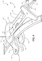
- FIG. 4 illustrates an isometric view of pectus bar assembly 100, which can include pectus bar 102, stabilizer 104, and stabilizer tool 106.
- Stabilizer 104 can include first portion 110, second portion 112, and stabilizer bore 142.
- Stabilizer tool 106 can include first handle 114, second handle 116, first head 118, second head 120, first arm 122, second arm 124, locking shaft 126, and joint 170.
- First head 118 can include driver pin bore 136, shaft pin bore 152, shaft pin 172, and locking shaft bore 178.
- Second head 120 can include contouring 174 and bar engagement portion 176.
- Locking shaft 126 can include locking handle 138.
- the components of FIG. 4 can connect and operate consistently with the components of FIGS. 1-3 ; however, FIG. 4 shows additional details of stabilizer tool 106.
- Joint 170 can be a revolute or hinged joint between first arm 122 and second arm 124, in some examples, to form a cross-link or scissor linkage between first arm 122 and second arm 124.
- This cross-link between first arm 122 and second arm 124 can enable handles 114 and 116 (of FIG. 1 ) to open and close first head 118 and 120.
- Shaft pin 172 can be a pin, having a shape such as a cylinder, or other prismatic shape, and can be comprised of a rigid material, such as plastics, metals, and the like. Shaft pin 172 can extend into first head 118, passing through shaft pin bore 152 near the entrance of locking shaft 126 and into first head 118. Shaft pin bore 152 can pass over locking shaft 126, so that shaft pin 172 can engage locking shaft 126, restricting axial translation locking shaft 126, while locking shaft bore 178 can restrict motion of driver 156 in other directions. Locking shaft bore 178 can be perpendicular to driver bore 148, extending from an outer portion of first head 118 and extending into first head 118 to intersect with driver bore 148.
- Second head 120 can include head contouring 174, which can be a perimeter wall or recess that is shaped to receive, or interface with, a stabilizer, such as stabilizer 104.
- Contouring 174 can be designed so that stabilizer 104 nests within second head 120 to limit movement of stabilizer 104 relative to second head 120 when first head 118 and second head 120 are in a closed position.
- Second head 120 can also include bar engagement portion 176, which can be a portion of second head 120 configured to engage pectus bar 102 without restricting motion of second head 120 and therefore stabilizer tool 106 relative to pectus bar 102 when first head 118 and second head 120 are in a closed position.
- bar engagement portion 176 can be a portion of second head 120 configured to engage pectus bar 102 without restricting motion of second head 120 and therefore stabilizer tool 106 relative to pectus bar 102 when first head 118 and second head 120 are in a closed position.
- FIG. 5 illustrates a partially exploded isometric view of pectus bar assembly 100.
- first head 118 is removed to more clearly show how some components of pectus bar assembly 102 connect and operate.
- Pectus bar assembly 100 can include pectus bar 102, stabilizer 104, and stabilizer tool 106.
- Stabilizer 104 can include first portion 110, second portion 112, stabilizer bores 140 and 142, and locking cam 144.
- Stabilizer tool 106 can include second head 120, second arm 124, locking shaft 126, and joint 170.
- Second head 120 can include contouring 174, bar engagement portion 176, and snap bore 180.
- Locking shaft 126 can include locking handle 138, pin groove 182, and worm gear 184.
- Driver 156 can include driver gear 162 (including teeth 164) and driver bit 166.
- the components of FIG. 5 can connect and operate consistently with the components of FIGS. 1-4 ; however, FIG. 5 shows additional details of stabilizer tool 106.
- Snap bore 180 can extend through second head 120.
- Snap bore 180 can be sized to be of a larger diameter than snap fitting 154 ( FIG. 3 ), including projections 168, so that snap fitting 154 can reside within snap bore 180 without applying pressure on either of projections 168, allowing second head 120 to enclose stabilizer 104 without interfering with snap fitting 154.
- Pin groove 182 can be a circumferential groove in locking shaft 126 proximate a distal end of locking shaft 126 and adjacent to worm gear 184. In some examples, pin groove 182 can be other types of retention devices, such as a snap ring. Pin groove 182 can be sized to engage shaft pin 172 such that shaft pin 172 prevents axial translation of locking shaft 126, but does not restrict rotation of locking shaft 126.
- Worm gear 184 can be disposed at a distal termination of locking shaft 126, in some examples, and at other locations along locking shaft 126 in other examples. Worm gear 184 can be integral to locking shaft 126 in some examples, and can be attached to locking shaft 126 (for example by welding or fastening), in some other examples. Worm gear 184 can be configured to interface with drive gear 162, and more specifically teeth 164 of drive gear 162, in some examples. In some other examples, different types of gears, such as a helical gear, can be used in place of worm gear 184.
- driver bit 166 is insertable into locking cam 144, as shown in FIG. 5 .
- locking shaft 126 such as locking handle 138
- worm gear 184 interfaces with teeth 164 of driver gear 162
- rotation of worm gear 184 causes rotation of driver gear 162 and therefore driver bit 166. That is, by rotating handle 138 of locking shaft 126, driver bit 166 is rotated, and can therefore be used to rotate locking cam 144, in either rotational direction, to lock and unlock locking cam 144 to and from, respectively, pectus bar 102.
- FIG. 6 shows a flow chart of using the devices and systems described above, in accordance with at least one example of this disclosure.
- the steps or operations of the method of FIG. 6 are illustrated in a particular order for convenience and clarity. Many of the discussed operations can be performed in a different sequence or in parallel, and some operations may be excluded, without materially impacting other operations.
- the method of FIG. 6 includes operations that may be performed by multiple different actors, devices, and/or systems. It is understood that subsets of the operations discussed in the method of FIG. 6 that are attributable to a single actor, device, or system could be considered a separate standalone process or method.
- a physician can create one or more incisions on a ribcage of a patient at step 602.
- Other preparations can be made at step 602, such as detachment of soft tissues and resection of ribs, in some examples.
- a pectus bar such as pectus bar 102
- a pectus bar can be inserted into the ribcage and woven through one or more ribs and/or cartilage of the patient. Once fully inserted, the pectus bar can be flipped into an orientation that supports a proper rib cage shape or configuration.
- the pectus bar can be directly secured to the patient's rib cage using sutures and/or fasteners, as necessary, passing through a bore of the pectus bar.
- a stabilizer such as stabilizer 104 of FIG. 2
- a stabilizer tool such as stabilizer tool 106 of FIG. 1
- a snap fitting of the stabilizer can engage a bore of the stabilizer to secure the stabilizer to the stabilizer tool.
- the stabilizer may also be supported by contouring of a head of the stabilizer tool, such as contouring 160 of FIG. 3 .
- the stabilizer can be attached to the pectus bar prior to attaching the stabilizer to the stabilizer tool.
- the stabilizer tool can be used to attach the stabilizer to the pectus bar and then positioned relative to the pectus bar at step 610.
- the stabilizer tool can then be used to lock a locking cam of the stabilizer to the pectus bar at step 612.
- the stabilizer tool can be used to unlock the stabilizer and the stabilizer can be repositioned on the pectus bar. Accordingly steps 606 through 612 can be repeated as necessary to lock the stabilizer to the pectus bar in the desired location.
- additional stabilizers can be installed and secured to the pectus bar at step 614.
- additional pectus bars can be installed at step 614, where each bar can receive zero, one, or more stabilizers.
- the additional stabilizers and/or pectus bars can be installed using any or all of steps 602-612.
- the procedure can be completed at step 616, which can include connecting soft tissues, such as muscles, ligaments, cartilage, tendons to bones and to each other, and can include closing the incision or incisions.
Landscapes
- Health & Medical Sciences (AREA)
- Orthopedic Medicine & Surgery (AREA)
- Life Sciences & Earth Sciences (AREA)
- Surgery (AREA)
- General Health & Medical Sciences (AREA)
- Animal Behavior & Ethology (AREA)
- Engineering & Computer Science (AREA)
- Biomedical Technology (AREA)
- Heart & Thoracic Surgery (AREA)
- Veterinary Medicine (AREA)
- Public Health (AREA)
- Medical Informatics (AREA)
- Molecular Biology (AREA)
- Nuclear Medicine, Radiotherapy & Molecular Imaging (AREA)
- Neurology (AREA)
- Cardiology (AREA)
- Oral & Maxillofacial Surgery (AREA)
- Transplantation (AREA)
- Vascular Medicine (AREA)
- Surgical Instruments (AREA)
- Apparatus For Disinfection Or Sterilisation (AREA)
- Materials For Medical Uses (AREA)
- Hooks, Suction Cups, And Attachment By Adhesive Means (AREA)
- Dental Prosthetics (AREA)
Description
- Pectus excavatum and pectus carinatum are conditions affecting a human rib cage which can result from a congenital disorder or deformity. In some cases of pectus excavatum and pectus carinatum, physicians install hardware into a patient's ribcage to reshape the ribcage. Depending on the anatomy of the patient, current hardware solutions may be difficult to secure to a patient. Further, because some surgical methods attempt to minimize the number and size of surgical incisions, hardware installed on the ribcage may be difficult for a physician to reach and/or secure.
- A pectus bar stabilizer insertion tool of the type claimed is known from the document
EP 1 721 580 A1 . - The scope of the invention is defined by the claims.
- The examples described below do not form part of the invention but provide information that is useful for understanding the invention.
- Associated surgical methods are also described herein to aid understanding the invention. These methods do not form part of the claimed invention.
- In cases where pectus carinatum or pectus excavatum require surgical correction, a common corrective procedure includes securing a pectus bar to a patient's rib cage to reshape and stabilize the rib cage. This procedure can include the steps of: creating opposing incisions on each side of a patient's rib cage; inserting a curved pectus bar into one of the incisions; weaving the pectus bar through one or more ribs; flipping the pectus bar; securing the pectus bar to the rib cage; securing one or more stabilizers to the pectus bar; securing the one or more stabilizers to the rib cage; and, closing the incisions.
- In some of these surgical procedures, incisions are located on an outer (lateral) portion of the rib cage for aesthetic purposes. In some of these procedures, stabilizers may be difficult for a physician to position on the pectus bar and the stabilizers may be difficult for a physician to secure to the pectus bar. The inventors have recognized, among other things, that a stabilizer tool can be used to secure a stabilizer to the tool, place the stabilizer on the pectus bar, and engage a lock of the stabilizer to secure the stabilizer to the pectus bar. These methods can simplify and shorten the surgical procedure and help reduce damage to components during the procedure, saving time and cost.
- To further illustrate the apparatuses and systems disclosed herein, the following non-limiting examples are provided:
- Example 1 is a pectus bar stabilizer insertion tool comprising: a first handle including a first distal portion; a second handle including a second distal portion, the second handle pivotably coupled to the first handle, the first and second handles moveable between an open position and a closed position; a first head coupled to the first distal portion and engageable with a first portion of a stabilizer, the first head including: a driver engageable with a lock of the stabilizer; a second head coupled to the second distal portion and engageable with a second portion of the stabilizer; and a locking shaft extending from the first head, the locking shaft coupled to the driver and operable to lock and unlock the stabilizer to a pectus bar.
- In Example 2, the subject matter of Example 1 optionally includes the first head further comprising a snap fitting extending from the first head generally towards the second head, the snap fitting engageable with the stabilizer to secure the stabilizer to the first head.
- In Example 3, the subject matter of Example 2 optionally includes the second head further comprising a snap bore alignable with the snap fitting when the first handle and second handle are in the closed position, the snap bore sized to be larger than the snap fitting.
- In Example 4, the subject matter of Example 3 optionally includes the stabilizer comprising a first stabilizer bore alignable with the snap bore when the first handle and second handle are in the closed position, and wherein the snap fitting is releasably securable to the first stabilizer bore.
- In Example 5, the subject matter of any one or more of Examples 1-4 is optionally configured such that the locking shaft includes a shaft circumferential groove, and the first head further comprises a first pin engaging the shaft circumferential groove to restrict translation of the locking shaft.
- In Example 6, the subject matter of any one or more of Examples 1-5 optionally includes the first head further comprising a second pin engaging the driver to restrict translation of the driver.
- In Example 7, the subject matter of any one or more of Examples 1-6 optionally includes a locking handle coupled to a proximal end of the locking shaft.
- In Example 8, the subject matter of any one or more of Examples 1-7 is optionally configured such that the driver comprises a gear, and the locking shaft comprises a worm drive disposed at a distal end of the locking shaft, the worm drive engageable with the gear to operate the driver.
- In Example 9, the subject matter of any one or more of Examples 1-8 is optionally configured such that the first head and the second head are contoured so that the stabilizer recesses into the first head and the second head when the stabilizer engages the first head and the second head.
- In Example 10, the subject matter of any one or more of Examples 1-9 is optionally configured such that the second head is contoured so that the pectus bar recesses into the second head when the pectus bar engages the second head.
- In Example 11, the subject matter of any one or more of Examples 1-10 optionally includes the first head further comprising a driver bore extending into the first head, the driver disposable in the driver bore.
- In Example 12, the subject matter of Example 11 optionally includes the first head further comprising a locking shaft bore extending into the first head from an outer surface of the first head substantially perpendicular to and intersecting the driver bore, allowing the locking shaft to engage the driver.
- Example 13 is a pectus bar assembly comprising: a pectus bar insertable into a human rib cage; a stabilizer securable to the pectus bar and to the human rib cage, the stabilizer comprising: a first portion including a locking cam; and a second portion opposite the first portion; and a stabilizer tool comprising: a first handle including a first distal portion; a second handle including a second distal portion, the second handle pivotably coupled to the first handle, the first and second handles moveable between an open position and a closed position; a first head coupled to the first distal portion and engageable with the first portion of the stabilizer, the first head including a driver engageable with the locking cam; a second head coupled to the second distal portion and engageable with the second portion of the stabilizer; and a locking shaft extending from the first head, the locking shaft coupled to the driver to operate the locking cam.
- In Example 14, the subject matter of Example 13 optionally includes the first head further comprising a snap fitting extending from the first head generally towards the second head, the snap fitting engageable with the stabilizer to secure the stabilizer to the first head.
- In Example 15, the subject matter of Example 14 optionally includes the second head further comprising a snap bore alignable with the snap fitting when the first handle and the second handle are in the closed position, the snap bore sized to be larger than the snap fitting.
- In Example 16, the subject matter of any one or more of Examples 13-15 is optionally configured such that the locking shaft includes a shaft circumferential groove, and the first head further comprises a first pin engaging the shaft circumferential groove to restrict translation of the locking shaft.
- In Example 17, the subject matter of any one or more of Examples 13-16 optionally includes the first head further comprising a second pin engaging the driver to restrict translation of the driver.
- In Example 18, the subject matter of any one or more of Examples 13-17 is optionally configured such that the driver comprises a gear, and the locking shaft further comprises a worm drive disposed at a distal end of the locking shaft, the worm drive engageable with the gear to operate the driver.
- Example 19 is a method of securing a stabilizer to a pectus bar, the method comprising: placing a stabilizer over a pectus bar using a stabilizer tool; operating a first handle and a second handle of the stabilizer tool to close a first head and a second head of the stabilizer tool around the pectus bar and the stabilizer, wherein closing the first head and the second head engages a driver of the first head with a locking cam of the stabilizer; and rotating a locking shaft of the stabilizer tool to lock the locking cam to the pectus bar.
- In Example 20, the subject matter of Example 19 optionally includes securing the stabilizer to a snap fitting of the first head.
- In Example 21, the subject matter of one or more of Examples 19-20 is optionally configured such that the first handle and the second handle are operated from a position outside an incision and the first head and second head are within the incision.
- In Example 22, the subject matter of one or more of Examples 19-21 optionally includes positioning the stabilizer on the pectus bar as desired when the first head and second head are closed and when the locking cam is unlocked.
- In Example 23, the subject matter of one or more of Examples 19-223 is optionally configured such that closing the first head and the second head causes the first head to engage a body of the stabilizer and the second head to engage the body of the stabilizer and the pectus bar.
- In Example 24, the pectus bar stabilizer insertion tool, assembly, or method of any one of or any combination of Examples 1-23 is optionally configured such that all elements or options recited are available to use or select from.
- These and other examples and features of the present apparatuses and systems will be set forth in part in the following Detailed Description. This Overview is intended to provide non-limiting examples of the present subject matter and it is not intended to provide an exclusive or exhaustive explanation. The Detailed Description below is included to provide further information about the present apparatuses.
- In the drawings, which are not necessarily drawn to scale, like numerals can describe similar components in different views. Like numerals having different letter suffixes can represent different instances of similar components. The drawings illustrate generally, by way of example, but not by way of limitation, various examples discussed in the present document.
-
FIG. 1 illustrates an isometric view of a pectus bar assembly, in accordance with at least one example of the present disclosure. -
FIG. 2 illustrates an isometric view of a stabilizer and pectus bar, in accordance with at least one example of the present disclosure. -
FIG. 3 illustrates an isometric view of a portion of a stabilizer tool, in accordance with at least one example of the present disclosure. -
FIG. 4 illustrates an isometric view of a pectus bar assembly, in accordance with at least one example of the present disclosure. -
FIG. 5 illustrates a partially exploded isometric view of a pectus bar assembly, in accordance with at least one example of the present disclosure. -
FIG. 6 illustrates a schematic of a method, in accordance with at least one example of the present disclosure. - The present application relates to devices and systems for pectus correction procedures. The present application discloses an assembly for coupling a pectus bar and stabilizers to a rib cage of a patient to correct pectus excavatum and pectus carinatum.
-
FIG. 1 illustrates an isometric view ofpectus bar assembly 100, which can includepectus bar 102,stabilizer 104, andstabilizer tool 106.Pectus bar 102 can include bar bores 108 (only one shown inFIG. 1 ). Stabilizer 104 can includefirst portion 110 andsecond portion 112.Stabilizer tool 106 can includefirst handle 114,second handle 116,first head 118,second head 120,first arm 122,second arm 124, andlocking shaft 126. -
Pectus bar 102 can be a rigid or semi-rigid bar constructed of materials such as metals and plastics.Pectus bar 102 can have an elongate body forming a curve, such as a c-shape, in some examples.Bar bores 108 can be disposed near the terminations ofpectus bar 102 and can be configured to receive fasteners, such as bone screws or sutures, to securepectus bar 102 to ribs and/or soft tissues (such as muscles and cartilage) of a patient. -
Stabilizer 104 can be a rigid or semi-rigid component constructed of materials such as metals and plastics.Stabilizer 104 can be configured to engage and secure topectus bar 102 anywhere along the length ofpectus bar 102.Stabilizer 104 can also include bores (discussed later) that can be used to securestabilizer 104 to ribs and/or soft tissues of the patient.Stabilizer 104 can also include a locking mechanism (shown and discussed below) that can be used to securestabilizer 104 topectus bar 102. First portion (or first side) 110 ofstabilizer 104 can be opposite second portion (or second side) 112. - First handle 114 of
stabilizer tool 106 can be coupled to a first end offirst arm 122 andfirst head 118 can be coupled to a second end offirst arm 122. Similarly,second handle 116 can be coupled to a first end ofsecond arm 124 andsecond head 120 can be coupled to a second end ofsecond arm 124.First arm 122 andsecond arm 124 can be pivotably coupled between first andsecond handles second heads - In operation of some examples, a procedure to correct pectus excavatum or pectus carinatum can include creating opposing incisions on each side of a patient's rib cage and inserting
pectus bar 102 into one of the incisions.Pectus bar 102 can then be weaved through one or more ribs of the patient and flipped into a final position. Thereafter,stabilizers 104 can be inserted into the incisions and secured topectus bar 102 and to the rib cage of the patient before final preparations are made and incisions are closed. During this process, a physician can positionstabilizers 104 along the length of the bar as desired. However, in some procedures, because of the lateral placement of incisions and because of a sometimes desired medial position ofstabilizer 104, placement ofstabilizer 104 and securing ofstabilizer 104 by hand may be difficult. In such cases,stabilizer tool 106 can be used to securestabilizer 104 tofirst portion 118 ofstabilizer tool 106.Stabilizer 104 and stabilizer tool can then be inserted into an incision and a physician can usefirst handle 114 andsecond handle 116 to positionstabilizer 104 onpectus bar 102 whenfirst handle 114 andsecond handle 116 are in an either an open or closed position, asstabilizer 104 is secured tofirst head 118. - Once
stabilizer 104 is positioned onpectus bar 102,first handle 114 andsecond handle 116 can be moved to a closed position, temporarily securingstabilizer 104 topectus bar 102. When the physician has positionedstabilizer 104 at a desired location onpectus bar 102 usingfirst handle 114 andsecond handle 116, the physician can rotate lockingshaft 126 to operate the locking mechanism ofstabilizer 104, lockingstabilizer 104 topectus bar 102 in the desired position.Stabilizer tool 106 thus enables a physician to place and secure a stabilizer on a pectus bar in a location relative to an incision that may otherwise be difficult to reach.Stabilizer 106 therefore can increase procedural efficiency, which can save time and cost. The details of the components ofpectus bar assembly 100 shown inFIG. 1 are discussed in further detail below. - In some examples,
stabilizer 104 can include recessedportion 128.Stabilizer tool 106 can include ratchetlock 130. First handle 114 can includefinger hole 132 andsecond handle 116 can includefinger hole 134.First head 118 can include driver pin bore 136. Lockingshaft 126 can include lockinghandle 138. - Recessed
portion 128 can be a recess that is open atsecond portion 112 ofstabilizer 104. Recessedportion 128 can be sized and shaped to receivepectus bar 102. In some other examples, recessedportion 128 can be open tofirst portion 110. A locking mechanism (discussed below inFIG. 2 ) can engagepectus bar 102 at recessedportion 128 to lockstabilizer 104 topectus bar 102. -
Ratchet lock 130 can connect tofirst arm 122 andsecond arm 124 proximatefirst handle 114 andsecond handle 116, respectively. In operation of some examples, ratchetlock 130 can temporarily fix the position offirst handle 114 relative tosecond handle 116 and thereforefirst head 118 relative tosecond head 120, for example in a closed position.Ratchet lock 130 can be released so thatfirst handle 114 andsecond handle 116 can be moved between open and closed positions. -
First head 118 can include driver pin bore 136, which can be used to secure a driver withinfirst head 118, as discussed further below. Lockingshaft 126 can include lockinghandle 138, which can be used to apply a torque to lockingshaft 126 in either rotational direction to operate the driver withinfirst head 118, as described further below. -
FIG. 2 illustrates an isometric view ofpectus bar 102 andstabilizer 104 ofpectus bar assembly 100.Pectus bar 102 can include bar bores 108 (one shown inFIG. 2 ).Stabilizer 104 can includefirst portion 110, second portion 112 (not clearly visible inFIG. 2 ), recessedportion 128, stabilizer bores 140 and 142, and lock 143, which can include lockingcam 144, cam bore 146, andtool engagement 148. - The components illustrated in
FIG. 1 can be connected and can operate consistently withFIG. 1 ; however,FIG. 2 shows additional details ofpectus bar 102 andstabilizer 104. For example,FIG.2 shows stabilizer bores 142, which can be used to securestabilizer 104 to bones, such as ribs, or soft tissues of a patient. Stabilizer bores 142 can be configured to receive fasteners, such as bone screws or sutures, in some examples. -
FIG. 2 also showslock 143 ofstabilizer 104, which can be a lock that is operable to securestabilizer 104 topectus bar 102 at recessedportion 128. More specifically, cam bore 146 can be a bore extending fromfirst portion 110 intostabilizer 104 and intersecting recessedportion 128. Cam bore 146 can include a captivated or integral slot that engages an integral tab of lockingcam 144.Cam 144 can be a rotatable member configured to receive a driver attool engagement 148.Tool engagement 148 can be configured to receive many types of drivers, such as slotted, cross-recess, hex, star, and the like.Cam 144 can include a tab engageable withbore 146, and can include a portion that engagespectus bar 102 to securestabilizer 104 thereto. In some examples the tab and its engagement withbore 146 can prevent passive rotation ofcam 144 and/or unlocking. - In operation of some examples,
stabilizer 104 can be placed and positioned onpectus bar 102 so that recessedportion 128 engagespectus bar 102. A driver, such as a driver ofstabilizer tool 106, as described below, can be inserted intotool engagement 148 and the driver can be rotated (for example in a clock-wise direction) to rotate lockingcam 144 to lock againstbore 146 andlock stabilizer 104 topectus bar 102. This process can be reversed by rotating the driver in the opposite direction (for example, in a counter-clock-wise direction) to rotate lockingcam 144, which can disengage lockingcam 144 from lockingbore 146 andpectus bar 102, so thatstabilizer 104 can be removed frompectus bar 102 or can be repositioned relative topectus bar 102. ThoughFIG. 2 shows only one type of locking cam and locking bore,stabilizer tool 106 can be used to drive many types of cams or fasteners. -
FIG. 3 illustrates an isometric view of a portion ofstabilizer tool 106, which can includefirst head 118,first arm 122, and lockingshaft 126.First head 118 can include driver pin bore 136,driver pin 150, shaft pin bore 152, snap fitting 154,driver 156, driver bore 158, andcontouring 160.Driver 156 can include driver gear 162 (including teeth 164) anddriver bit 166. Snap fitting 154 can includeprojections 168. Also shown inFIG. 3 are orientation indicators Left and Right. The components ofFIG. 3 can connect and operate consistently with the components ofFIGS. 1 and2 ; however,FIG. 3 shows additional details ofstabilizer tool 106. -
First arm 122 can connect to a right portion offirst head 118 and lockingshaft 126 can enterfirst head 118 at a left portion offirst head 118. Lockingshaft 126 can terminate within the left portion offirst head 118, and can engagedriver 156 withinfirst head 118, as described further below. -
Driver pin 150 can be a pin, having a shape such as a cylinder, or other prismatic shape, and can be comprised of a rigid material, such as plastics, metals, and the like.Driver pin 150 can extend throughfirst head 118, passing through driver pin bore 136 at a medial location of first head 118 (between left and right portions of first head 118). Driver pin bore 136 can pass overdriver 156, so thatdriver pin 150 can engagedriver 156, restricting axial motion ofdriver 156, while driver bore restricts motion ofdriver 156 in other directions. - Shaft pin bore 152 can be a bore extending through the left portion of
first head 118, proximate a termination of locking shaft 126 (as discussed further below). - Snap fitting 154 extends from a surface of a right portion of first head 118 (generally towards
second head 120 ofFIG. 1 ). Though only one snap fitting is shown inFIG. 3 , more snap fittings, such as 1, 3, 4, 5, 10, and the like can be used. Snap fitting 154 includes two prongs, each having aprojection 164 extending radially from each prong of snap fitting 154.Projections 168 can have a radius or diameter that is larger than that of a portion of the prongs connecting tofirst head 118. - The prongs of snap fitting 154 are shown as being separated by a gap or slot, so that any force transverse to an axis of the snap fitting can cause one or both of the prongs to breach the gap, reducing the total diameter of snap fitting 154. When the diameter of snap fitting 154 is reduced, snap fitting 154 can be inserted into a bore having a diameter smaller than that of
projections 168 when snap fitting 154 is uncompressed.Projections 168 can expand to their normal diameter whenprojections 168 clear the bore, such as one of stabilizer bores 140 and 142 ofFIG. 2 . In the same way, when the prongs orprojections 168 are compressed, snap fitting can disengage from a bore. -
Driver 156 can be disposed in a bore offirst head 118, such as driver bore 158. Driver bore 158 can be circular in some examples, and can be of other shapes, such as octagonal, in other examples. Driver bore 158 can be sized to allowdriver 156 to rotate within driver bore 158 without impeding the rotation ofdriver 156, while limiting substantial non-rotational movement ofdriver 156 relative todriver bore 158. -
Driver 156 can includedriver gear 162, which can be a parallel axis gear, such as a spur gear, in some examples.Driver gear 162 can interface with a gear of lockingshaft 126 atteeth 164 ofdriver gear 162, as shown inFIG. 5 below.Driver bit 166 can extend from a non-geared surface ofdriver gear 162 and can protrude from driver bore. The interaction betweendriver gear 162 and lockingshaft 126 is discussed below in further detail inFIG. 5 . -
First head 118 can includehead contouring 160, which can be a perimeter wall that is shaped to receive, or interface with, a stabilizer, such asstabilizer 104 ofFIGS. 1 and2 . Contouring 160 can be designed so thatstabilizer 104 nests withinfirst head 118 to limit movement ofstabilizer 104 relative tofirst head 118 whenstabilizer 104 is secured by snap fitting 154 and/ordriver 156, as discussed further below. - In operation of some examples, snap fitting 154 can be used to secure a stabilizer, such as
stabilizer 104 ofFIGS. 1 and2 , tofirst head 118. That is, snap fitting 154 offirst head 118 can be aligned with a bore ofstabilizer 104, such asbores FIG. 2 . A force can then be applied to first head 118 (for example using first handle 114) andstabilizer 104 so that the walls or edges of the bore apply a force toprojections 168, compressing the prongs of snap fitting 154, reducing the diameter of snap fitting 154, and allowing snap fitting 154 to enter the bore. Whenprojections 168 have passed through the bore,projections 168 can expand, securingstabilizer 104 tostabilizer tool 106. In this position,stabilizer 104 can be nested within contouring 160 ofhead 118, further securingstabilizer 104 tofirst head 118. - Once
stabilizer 104 is coupled tostabilizer tool 106,stabilizer tool 106 can be used to positionstabilizer 104 onpectus bar 102. In another example,stabilizer 104 can be placed onpectus bar 102 before securingstabilizer 104 tostabilizer tool 106. In either case, after couplingstabilizer tool 106 tostabilizer 104,stabilizer tool 106 can be closed usingfirst handle 114 andsecond handle 116, securingstabilizer 104 topectus bar 102, without locking the position ofstabilizer 104 relative topectus bar 102.Stabilizer 104 can then be positioned at any desired location onpectus bar 102 without losing an interface betweenstabilizer 104 andpectus bar 102.
Whenstabilizer tool 106 is in a closed position,driver 156, and more specifically,driver bit 166, can engagetool engagement portion 148 of locking cam 144 (as shown inFIG. 5 below). When stabilizer tool is in this position, lockingshaft 126 can be rotated to rotatedriver bit 166 in either direction. Rotatingdriver bit 166 in a clock-wise direction, in some examples, can lockcam lock 144 topectus bar 102, securingstabilizer 104 topectus bar 102. Oncestabilizer 104 is locked topectus bar 102,first handle 114 andsecond handle 116 can be opened, forcingprojections 168 to engage an outside portion of one of stabilizer bores 140 and 142, forcingprojections 168 inward, compressing snap fitting 154 so that snap fitting 154 can pass through the bore andstabilizer tool 106 can be entirely disengaged fromstabilizer 104 and removed from the patient. In this way,stabilizer tool 106 allows a physician to install a stabilizer in positions that may otherwise be difficult to reach or difficult or undesirable to place by hand.Stabilizer tool 106 also allows for positioning or repositioning ofstabilizer 104 onto a pectus bar from a position outside an incision. Becausestabilizer tool 106 provides a single device for securing, placing, and locking a stabilizer to a pectus bar, stabilizer tool can increase procedural efficiency, saving time and cost. -
FIG. 4 illustrates an isometric view ofpectus bar assembly 100, which can includepectus bar 102,stabilizer 104, andstabilizer tool 106.Stabilizer 104 can includefirst portion 110,second portion 112, andstabilizer bore 142.Stabilizer tool 106 can includefirst handle 114,second handle 116,first head 118,second head 120,first arm 122,second arm 124, lockingshaft 126, and joint 170.First head 118 can include driver pin bore 136, shaft pin bore 152,shaft pin 172, and lockingshaft bore 178.Second head 120 can includecontouring 174 andbar engagement portion 176. Lockingshaft 126 can include lockinghandle 138. The components ofFIG. 4 can connect and operate consistently with the components ofFIGS. 1-3 ; however,FIG. 4 shows additional details ofstabilizer tool 106. - Joint 170 can be a revolute or hinged joint between
first arm 122 andsecond arm 124, in some examples, to form a cross-link or scissor linkage betweenfirst arm 122 andsecond arm 124. This cross-link betweenfirst arm 122 andsecond arm 124 can enablehandles 114 and 116 (ofFIG. 1 ) to open and closefirst head -
Shaft pin 172 can be a pin, having a shape such as a cylinder, or other prismatic shape, and can be comprised of a rigid material, such as plastics, metals, and the like.Shaft pin 172 can extend intofirst head 118, passing through shaft pin bore 152 near the entrance of lockingshaft 126 and intofirst head 118. Shaft pin bore 152 can pass over lockingshaft 126, so thatshaft pin 172 can engage lockingshaft 126, restricting axialtranslation locking shaft 126, while locking shaft bore 178 can restrict motion ofdriver 156 in other directions. Locking shaft bore 178 can be perpendicular to driver bore 148, extending from an outer portion offirst head 118 and extending intofirst head 118 to intersect withdriver bore 148. -
Second head 120 can includehead contouring 174, which can be a perimeter wall or recess that is shaped to receive, or interface with, a stabilizer, such asstabilizer 104. Contouring 174 can be designed so thatstabilizer 104 nests withinsecond head 120 to limit movement ofstabilizer 104 relative tosecond head 120 whenfirst head 118 andsecond head 120 are in a closed position. -
Second head 120 can also includebar engagement portion 176, which can be a portion ofsecond head 120 configured to engagepectus bar 102 without restricting motion ofsecond head 120 and thereforestabilizer tool 106 relative topectus bar 102 whenfirst head 118 andsecond head 120 are in a closed position. -
FIG. 5 illustrates a partially exploded isometric view ofpectus bar assembly 100. InFIG. 5 ,first head 118 is removed to more clearly show how some components ofpectus bar assembly 102 connect and operate. -
Pectus bar assembly 100 can includepectus bar 102,stabilizer 104, andstabilizer tool 106.Stabilizer 104 can includefirst portion 110,second portion 112, stabilizer bores 140 and 142, and lockingcam 144.Stabilizer tool 106 can includesecond head 120,second arm 124, lockingshaft 126, and joint 170.Second head 120 can includecontouring 174,bar engagement portion 176, and snap bore 180. Lockingshaft 126 can include lockinghandle 138,pin groove 182, andworm gear 184.Driver 156 can include driver gear 162 (including teeth 164) anddriver bit 166. The components ofFIG. 5 can connect and operate consistently with the components ofFIGS. 1-4 ; however,FIG. 5 shows additional details ofstabilizer tool 106. - Snap bore 180 can extend through
second head 120. Snap bore 180 can be sized to be of a larger diameter than snap fitting 154 (FIG. 3 ), includingprojections 168, so that snap fitting 154 can reside within snap bore 180 without applying pressure on either ofprojections 168, allowingsecond head 120 to enclosestabilizer 104 without interfering with snap fitting 154. -
Pin groove 182 can be a circumferential groove in lockingshaft 126 proximate a distal end of lockingshaft 126 and adjacent toworm gear 184. In some examples,pin groove 182 can be other types of retention devices, such as a snap ring.Pin groove 182 can be sized to engageshaft pin 172 such thatshaft pin 172 prevents axial translation of lockingshaft 126, but does not restrict rotation of lockingshaft 126. -
Worm gear 184 can be disposed at a distal termination of lockingshaft 126, in some examples, and at other locations along lockingshaft 126 in other examples.Worm gear 184 can be integral to lockingshaft 126 in some examples, and can be attached to locking shaft 126 (for example by welding or fastening), in some other examples.Worm gear 184 can be configured to interface withdrive gear 162, and more specificallyteeth 164 ofdrive gear 162, in some examples. In some other examples, different types of gears, such as a helical gear, can be used in place ofworm gear 184. - In operation of some examples,
driver bit 166 is insertable into lockingcam 144, as shown inFIG. 5 . Whendriver bit 166 engages lockingcam 144, locking shaft 126 (such as locking handle 138) can be rotated, which in turn rotatesworm gear 184. Becauseworm gear 184 interfaces withteeth 164 ofdriver gear 162, rotation ofworm gear 184 causes rotation ofdriver gear 162 and thereforedriver bit 166. That is, by rotatinghandle 138 of lockingshaft 126,driver bit 166 is rotated, and can therefore be used to rotate lockingcam 144, in either rotational direction, to lock and unlock lockingcam 144 to and from, respectively,pectus bar 102. -
FIG. 6 shows a flow chart of using the devices and systems described above, in accordance with at least one example of this disclosure. The steps or operations of the method ofFIG. 6 are illustrated in a particular order for convenience and clarity. Many of the discussed operations can be performed in a different sequence or in parallel, and some operations may be excluded, without materially impacting other operations. The method ofFIG. 6 , as discussed, includes operations that may be performed by multiple different actors, devices, and/or systems. It is understood that subsets of the operations discussed in the method ofFIG. 6 that are attributable to a single actor, device, or system could be considered a separate standalone process or method. - In operation of one example, a physician can create one or more incisions on a ribcage of a patient at
step 602. Other preparations can be made atstep 602, such as detachment of soft tissues and resection of ribs, in some examples. Atstep 604, a pectus bar, such aspectus bar 102, can be inserted into the ribcage and woven through one or more ribs and/or cartilage of the patient. Once fully inserted, the pectus bar can be flipped into an orientation that supports a proper rib cage shape or configuration. At any point afterstep 604 and prior to step 616, the pectus bar can be directly secured to the patient's rib cage using sutures and/or fasteners, as necessary, passing through a bore of the pectus bar. - At
step 606, a stabilizer, such asstabilizer 104 ofFIG. 2 , can be attached to a stabilizer tool, such asstabilizer tool 106 ofFIG. 1 . Specifically, a snap fitting of the stabilizer can engage a bore of the stabilizer to secure the stabilizer to the stabilizer tool. The stabilizer may also be supported by contouring of a head of the stabilizer tool, such ascontouring 160 ofFIG. 3 . In some examples, the stabilizer can be attached to the pectus bar prior to attaching the stabilizer to the stabilizer tool. - At
step 608, the stabilizer tool can be used to attach the stabilizer to the pectus bar and then positioned relative to the pectus bar atstep 610. The stabilizer tool can then be used to lock a locking cam of the stabilizer to the pectus bar atstep 612. Followingstep 612, if necessary, the stabilizer tool can be used to unlock the stabilizer and the stabilizer can be repositioned on the pectus bar. Accordingly steps 606 through 612 can be repeated as necessary to lock the stabilizer to the pectus bar in the desired location. - Once the stabilizer is locked to the pectus bar at a desired location, additional stabilizers can be installed and secured to the pectus bar at
step 614. Also, if necessary, additional pectus bars can be installed atstep 614, where each bar can receive zero, one, or more stabilizers. The additional stabilizers and/or pectus bars can be installed using any or all of steps 602-612. - After a desired quantity of pectus bars and stabilizers have been installed, the procedure can be completed at
step 616, which can include connecting soft tissues, such as muscles, ligaments, cartilage, tendons to bones and to each other, and can include closing the incision or incisions.
Claims (15)
- A pectus bar stabilizer insertion tool (106) comprising:a first handle (114) including a first distal portion (122);a second handle (116) including a second distal portion (124), the second handle pivotably coupled to the first handle, the first and second handles moveable between an open position and a closed position;a first head (118) coupled to the first distal portion and engageable with a first portion of a stabilizer (104), the first head including:
a driver (156) engageable with a lock of the stabilizer;a second head (120) coupled to the second distal portion and engageable with a second portion of the stabilizer; anda locking shaft (126) extending from the first head, the locking shaft coupled to the driver and operable to lock and unlock the stabilizer to a pectus bar. - The insertion tool of claim 1, the first head further comprising:
a snap fitting (154) extending from the first head generally towards the second head, the snap fitting engageable with the stabilizer to secure the stabilizer to the first head. - The insertion tool of any of claims 1-2, the second head further comprising a snap bore (180) alignable with the snap fitting when the first handle and second handle are in the closed position, the snap bore sized to be larger than the snap fitting.
- The insertion tool of any of claims 1-3, the stabilizer comprising a first stabilizer bore (140) alignable with the snap bore when the first handle and second handle are in the closed position, and wherein the snap fitting is releasably securable to the first stabilizer bore.
- The insertion tool of any of claims 1-4, wherein:the locking shaft includes a shaft circumferential groove (182); andthe first head further comprising a first pin (172) engaging the shaft circumferential groove to restrict translation of the locking shaft.
- The insertion tool of any of claims 1-5, the first head further comprising a second pin (136) engaging the driver to restrict translation of the driver.
- The insertion tool of any of claims 1-6, further comprising a locking handle (138) coupled to a proximal end of the locking shaft.
- The insertion tool of any of claims 1-7, wherein:the driver comprises a gear (162); andthe locking shaft comprises a worm drive (184) disposed at a distal end of the locking shaft, the worm drive engageable with the gear to operate the driver.
- The insertion tool of any of claims 1-8, wherein the first head and the second head are contoured so that the stabilizer recesses into the first head and the second head when the stabilizer engages the first head and the second head.
- The insertion tool of any of claims 1-9, wherein the second head is contoured so that the pectus bar recesses into the second head when the pectus bar engages the second head.
- The insertion tool of any of claims 1-10, wherein the first head further comprising a driver bore (158) extending into the first head, the driver is disposable in the driver bore.
- The insertion tool of any of claims 1-11, wherein the first head further comprising a locking shaft bore (178) extending into the first head from an outer surface of the first head substantially perpendicular to and intersecting the driver bore, allowing the locking shaft to engage the driver.
- A pectus bar assembly (100) comprising:a pectus bar (102) insertable into a human rib cage;a stabilizer securable to the pectus bar and to the human rib cage, the stabilizer comprising:a first portion (110) including a locking cam (144); anda second portion (112) opposite the first portion; anda stabilizer insertion tool (106) comprising:a first handle (114) including a first distal portion (122);a second handle (116) including a second distal portion (124), the second handle pivotably coupled to the first handle, the first and second handles moveable between an open position and a closed position;a first head (118) coupled to the first distal portion and engageable with the first portion of the stabilizer, the first head including a driver (156) engageable with the locking cam (144);a second head (120) coupled to the second distal portion and engageable with the second portion of the stabilizer; anda locking shaft (126) extending from the first head, the locking shaft coupled to the driver to operate the locking cam.
- The pectus bar assembly of claim 13, the first head further comprising:
a snap fitting extending from the first head generally towards the second head, the snap fitting engageable with the stabilizer to secure the stabilizer to the first head. - The pectus bar assembly of any of claims 13-14, the second head further comprising:
a snap bore alignable with the snap fitting when the first handle and the second handle are in the closed position, the snap bore sized to be larger than the snap fitting.
Applications Claiming Priority (3)
| Application Number | Priority Date | Filing Date | Title |
|---|---|---|---|
| US201762457532P | 2017-02-10 | 2017-02-10 | |
| US201762483494P | 2017-04-10 | 2017-04-10 | |
| PCT/US2018/017591 WO2018148521A1 (en) | 2017-02-10 | 2018-02-09 | Stabilizer holder and inserter tool and methods |
Publications (2)
| Publication Number | Publication Date |
|---|---|
| EP3579773A1 EP3579773A1 (en) | 2019-12-18 |
| EP3579773B1 true EP3579773B1 (en) | 2021-10-06 |
Family
ID=61274364
Family Applications (2)
| Application Number | Title | Priority Date | Filing Date |
|---|---|---|---|
| EP18707802.7A Active EP3579773B1 (en) | 2017-02-10 | 2018-02-09 | Stabilizer holder and inserter tool |
| EP18707204.6A Active EP3579772B1 (en) | 2017-02-10 | 2018-02-09 | Pectus bar and stabilizer devices |
Family Applications After (1)
| Application Number | Title | Priority Date | Filing Date |
|---|---|---|---|
| EP18707204.6A Active EP3579772B1 (en) | 2017-02-10 | 2018-02-09 | Pectus bar and stabilizer devices |
Country Status (7)
| Country | Link |
|---|---|
| US (4) | US10722279B2 (en) |
| EP (2) | EP3579773B1 (en) |
| JP (1) | JP7130654B2 (en) |
| CN (1) | CN110325135A (en) |
| AU (1) | AU2018217805B2 (en) |
| CA (1) | CA3053113C (en) |
| WO (2) | WO2018148572A1 (en) |
Families Citing this family (4)
| Publication number | Priority date | Publication date | Assignee | Title |
|---|---|---|---|---|
| US10722279B2 (en) | 2017-02-10 | 2020-07-28 | Zimmer Biomet CMF and Thoracic, LLC | Stabilizer holder and inserter tool and methods |
| EP3592267B1 (en) | 2017-03-08 | 2023-10-25 | Zimmer Biomet CMF And Thoracic, LLC | Pectus bar assembly |
| RU2741235C1 (en) * | 2020-03-02 | 2021-01-22 | Государственное автономное учреждение здравоохранения "Республиканская клиническая больница Министерства здравоохранения Республики Татарстан" | Plate for stabilization of thorax |
| WO2024186931A1 (en) | 2023-03-06 | 2024-09-12 | Zimmer Biomet CMF and Thoracic, LLC | Pectus bar and stabilizer devices |
Family Cites Families (80)
| Publication number | Priority date | Publication date | Assignee | Title |
|---|---|---|---|---|
| US212242A (en) | 1879-02-11 | Improvement in bar-holders for doors and windows | ||
| US2616328A (en) * | 1951-02-01 | 1952-11-04 | William F Mathias Jr | Fastener |
| US3693616A (en) * | 1970-06-26 | 1972-09-26 | Robert Roaf | Device for correcting scoliotic curves |
| DK279374A (en) | 1973-05-28 | 1975-01-20 | Protek Ag | |
| US4082332A (en) | 1977-01-27 | 1978-04-04 | Palmer Wayne D | Security apparatus |
| US4201215A (en) | 1977-09-06 | 1980-05-06 | Crossett E S | Apparatus and method for closing a severed sternum |
| US4202327A (en) | 1978-05-24 | 1980-05-13 | Glancy John J | Dynamic orthotic device |
| FR2469176B1 (en) | 1979-11-13 | 1986-03-14 | Corvisier Pierre | COSTAL ATTELLE |
| US5092889A (en) | 1989-04-14 | 1992-03-03 | Campbell Robert M Jr | Expandable vertical prosthetic rib |
| EP0583520A1 (en) | 1992-08-18 | 1994-02-23 | Nauchno-Proizvodstennoe Obiedinenie " Ekran" | Device for treating funnel chest |
| US5601554A (en) * | 1993-03-04 | 1997-02-11 | Advanced Spine Fixation Systems, Inc. | Branch connector for spinal fixation systems |
| AU701181B2 (en) | 1995-06-01 | 1999-01-21 | Depuy Orthopaedics, Inc. | Augmentation device for joint prostheses |
| AU5935196A (en) * | 1995-06-06 | 1996-12-24 | Sdgi Holdings, Inc. | Device for linking adjacent rods in spinal instrumentation |
| US5605364A (en) | 1995-07-11 | 1997-02-25 | Shelledy; Jack R. | Doorway security device and method of using same |
| US5755808A (en) | 1996-06-27 | 1998-05-26 | Joint Medical Products, Corporation | Connector plug for multi-component orthopedic implant |
| JP4467647B2 (en) | 1997-02-11 | 2010-05-26 | ウォーソー・オーソペディック・インコーポレーテッド | Bone plating system |
| US6007538A (en) | 1997-07-25 | 1999-12-28 | Duke University | Sternal closure device |
| FR2766353B1 (en) | 1997-07-28 | 1999-11-26 | Dimso Sa | IMPLANT, ESPECIALLY ANTERIOR CERVICAL PLATE |
| US6024759A (en) | 1998-05-08 | 2000-02-15 | Walter Lorenz Surgical, Inc. | Method and apparatus for performing pectus excavatum repair |
| US6355038B1 (en) | 1998-09-25 | 2002-03-12 | Perumala Corporation | Multi-axis internal spinal fixation |
| DE19950252C2 (en) | 1999-10-18 | 2002-01-17 | Schaefer Micomed Gmbh | bone plate |
| US6666867B2 (en) | 2001-02-15 | 2003-12-23 | Fast Enetix, Llc | Longitudinal plate assembly having an adjustable length |
| US6872210B2 (en) | 2001-02-23 | 2005-03-29 | James P. Hearn | Sternum fixation device |
| US6755833B1 (en) | 2001-12-14 | 2004-06-29 | Kamaljit S. Paul | Bone support assembly |
| US7303564B2 (en) | 2002-02-01 | 2007-12-04 | Spinal Concepts, Inc. | Spinal plate extender system and method |
| JP3708883B2 (en) * | 2002-02-08 | 2005-10-19 | 昭和医科工業株式会社 | Vertebral space retainer |
| KR100504682B1 (en) | 2002-09-28 | 2005-08-05 | 메딕스얼라인 주식회사 | implant for the repair of a pectus excavatum |
| AR037254A1 (en) * | 2002-11-06 | 2004-11-03 | Horacio Abramson | AN APPARATUS FOR CORRECTION OF MALFORMATIONS OF THE TORACICA BOX, SUCH AS "PECTUS EXCAVATUM" AND "PECTUS CARINATUM" AND METHOD FOR CORRECTION OF "PECTUS CARINATUM" |
| US20040116931A1 (en) | 2002-12-17 | 2004-06-17 | Carlson Gregory D. | Vertebrae fixation device and method of use |
| WO2004062482A2 (en) | 2003-01-10 | 2004-07-29 | Abdou Samy M | Plating system for bone fixation and subsidence and method of implantation |
| US20050049595A1 (en) * | 2003-09-03 | 2005-03-03 | Suh Sean S. | Track-plate carriage system |
| US20060089648A1 (en) | 2004-10-27 | 2006-04-27 | Masini Michael A | Versatile bone plate systems particularly suited to minimally invasive surgical procedures |
| US7601165B2 (en) | 2006-09-29 | 2009-10-13 | Biomet Sports Medicine, Llc | Method and apparatus for forming a self-locking adjustable suture loop |
| US8070749B2 (en) | 2005-05-12 | 2011-12-06 | Stern Joseph D | Revisable anterior cervical plating system |
| US20060259141A1 (en) | 2005-05-13 | 2006-11-16 | Walter Lorenz Surgical, Inc. | Pectus bar stabilizer |
| US8597327B2 (en) | 2006-02-03 | 2013-12-03 | Biomet Manufacturing, Llc | Method and apparatus for sternal closure |
| EP2007321B1 (en) * | 2006-04-03 | 2016-05-11 | Ib Medical, Llc | Static compression device |
| WO2008021656A2 (en) * | 2006-07-21 | 2008-02-21 | Merlot Orthopedix, Inc. | Apparatus and method for body tissue fixation |
| DE102006042277B4 (en) | 2006-09-08 | 2011-07-28 | MEDXPERT GmbH, 79423 | Implant for osteosynthesis, fixation and stabilization of long bones and implant system |
| US20080262549A1 (en) | 2006-10-19 | 2008-10-23 | Simpirica Spine, Inc. | Methods and systems for deploying spinous process constraints |
| US8974496B2 (en) | 2007-08-30 | 2015-03-10 | Jeffrey Chun Wang | Interspinous implant, tools and methods of implanting |
| KR100828111B1 (en) | 2007-08-28 | 2008-05-07 | 박형주 | Orthodontic Rod Fixture |
| CN201481536U (en) | 2009-08-14 | 2010-05-26 | 上海交通大学医学院附属新华医院 | Plate for orthopedic surgery of pectus pectus excavatum |
| RU2523362C2 (en) | 2010-02-10 | 2014-07-20 | Мессье-Довти Лтд | Chassis with steering axle |
| US20110251540A1 (en) | 2010-04-13 | 2011-10-13 | David Notrica | Apparatus and method for treating pectus excavatum |
| EP2465457B1 (en) | 2010-12-16 | 2014-04-30 | Zimmer Spine | Device for securing a ligature to an osseous structure |
| CN201930064U (en) | 2011-01-27 | 2011-08-17 | 常州市南翔医疗器械有限公司 | Metal bone setting plate for chest rib orthopaedics |
| FR2975582B1 (en) * | 2011-05-23 | 2013-06-07 | Ass Marie Lannelongue | OSTEOSYNTHESIS IMPLANT |
| EP2725998B1 (en) | 2011-06-29 | 2016-08-10 | Biomet Microfixation, Llc | Locking mechanism to secure ends of an implantable fabric |
| JP6240076B2 (en) | 2011-09-30 | 2017-11-29 | アキュート・イノヴェーションズ・エルエルシー | Bone fixation system with opposing mounting parts |
| DE102012104978A1 (en) | 2012-06-08 | 2013-12-12 | Medxpert Gmbh | Multidirectional thoracic wall stabilization |
| US9550611B2 (en) | 2012-10-26 | 2017-01-24 | Huhtamaki, Inc. | Lid and closure member assembly |
| CN203059880U (en) | 2013-03-06 | 2013-07-17 | 新疆维吾尔自治区人民医院 | Pectus excavatum treatment support plate fixer and pectus excavatum correction device |
| EP3498207B1 (en) * | 2013-03-15 | 2026-02-25 | Biomet Microfixation, Llc | Sternal closure cerclage, plate implant and instrumentation |
| JP6309975B2 (en) * | 2013-03-15 | 2018-04-11 | ホウフ,ルイス | Sternum fixation device and method |
| US10010359B2 (en) | 2013-03-15 | 2018-07-03 | Zimmer Biomet CMF and Thoracic, LLC | Sternal closure cerclage, plate implant and instrumentation |
| US10219849B2 (en) | 2013-07-03 | 2019-03-05 | The Charlotte Mecklenburg Hospital Authority | Device and system for supporting and approximating ribs |
| KR102301267B1 (en) * | 2013-07-09 | 2021-09-15 | 디퍼이 신테스 프로덕츠, 인코포레이티드 | Bone fixation device |
| ITPI20130090A1 (en) * | 2013-10-16 | 2015-04-17 | Scuola Superiore Di Studi Universit Ari E Di Perfe | APPARATUS FOR CORRECTION OF PECTUS EXCAVATUM PATHOLOGY. |
| US10441329B2 (en) * | 2013-10-28 | 2019-10-15 | Jace Medical, Llc | Orthopedic fixation device, system and method |
| US9743968B2 (en) * | 2013-11-14 | 2017-08-29 | Zimmer Biomet CMF and Thoracic, LLC | Locking mechanism for pectus bar |
| US10070904B2 (en) | 2014-02-21 | 2018-09-11 | Jeko Metodiev Madjarov | Bone fixation implants |
| US10076372B2 (en) | 2014-02-21 | 2018-09-18 | Jeko Metodiev Madjarov | Bone fixation implants and methods |
| CN103767778A (en) | 2014-03-01 | 2014-05-07 | 高艳香 | Rib fracture setting device |
| EP3116424B1 (en) | 2014-03-14 | 2019-06-12 | Zimmer Biomet Cmf And Thoracic, Llc | Sternal closure cerclage, plate implant and instrumentation |
| JP2016168086A (en) | 2015-03-11 | 2016-09-23 | 大阪コートロープ株式会社 | Tying buckle and funiculus body with buckle |
| US10238439B2 (en) * | 2015-04-24 | 2019-03-26 | Meditech Spine, Llc | Anterior spinal bone plate holding system and method |
| CN204683752U (en) | 2015-05-21 | 2015-10-07 | 柳立军 | Flail chest therapy equipment |
| CN104856748B (en) * | 2015-06-02 | 2017-09-29 | 北京纳通科技集团有限公司 | A kind of spinal fixation system |
| JP6857410B2 (en) | 2015-08-05 | 2021-04-14 | パク, ヒュン ジョPARK, Hyung Joo | Medical device for corrective surgery for funnel chest malformation |
| US10265109B2 (en) * | 2016-02-02 | 2019-04-23 | Life Spine, Inc. | Spine plate implant with cam lock bone screw retention |
| US10758290B2 (en) | 2016-03-11 | 2020-09-01 | Jace Medical, Llc | Orthopaedic fixation devices, systems and methods |
| US10786294B2 (en) | 2016-03-16 | 2020-09-29 | Pampamed Srl | Zip to the rib sternal pull-back system and method for pectus carinatum treatment |
| JP6607588B2 (en) | 2017-01-05 | 2019-11-20 | 学校法人 川崎学園 | Funnel chest correction bar fixture and funnel chest correction device |
| US10722279B2 (en) | 2017-02-10 | 2020-07-28 | Zimmer Biomet CMF and Thoracic, LLC | Stabilizer holder and inserter tool and methods |
| EP3592267B1 (en) | 2017-03-08 | 2023-10-25 | Zimmer Biomet CMF And Thoracic, LLC | Pectus bar assembly |
| TWI627934B (en) | 2017-04-20 | 2018-07-01 | 蘇世寬 | Self-adjustable repair system of pectus excavatum |
| US20180310973A1 (en) | 2017-04-26 | 2018-11-01 | Seung-Jin Lee | Orthopedic apparatus for pectus excavatum |
| US20180368896A1 (en) | 2017-06-22 | 2018-12-27 | Ledford Lee Powell | Rib fixation device |
| US11185358B2 (en) | 2017-08-31 | 2021-11-30 | Medical Design Innovation, Llc | Apparatus and methods for treating pectus excavatum |
-
2018
- 2018-02-09 US US15/892,926 patent/US10722279B2/en active Active
- 2018-02-09 CN CN201880011148.1A patent/CN110325135A/en active Pending
- 2018-02-09 WO PCT/US2018/017663 patent/WO2018148572A1/en not_active Ceased
- 2018-02-09 CA CA3053113A patent/CA3053113C/en active Active
- 2018-02-09 EP EP18707802.7A patent/EP3579773B1/en active Active
- 2018-02-09 US US15/893,271 patent/US10820931B2/en active Active
- 2018-02-09 EP EP18707204.6A patent/EP3579772B1/en active Active
- 2018-02-09 JP JP2019543354A patent/JP7130654B2/en active Active
- 2018-02-09 AU AU2018217805A patent/AU2018217805B2/en active Active
- 2018-02-09 WO PCT/US2018/017591 patent/WO2018148521A1/en not_active Ceased
-
2020
- 2020-06-22 US US16/908,188 patent/US11432858B2/en active Active
- 2020-09-28 US US17/034,697 patent/US11633218B2/en active Active
Also Published As
| Publication number | Publication date |
|---|---|
| JP2020508102A (en) | 2020-03-19 |
| WO2018148572A1 (en) | 2018-08-16 |
| US11432858B2 (en) | 2022-09-06 |
| WO2018148521A1 (en) | 2018-08-16 |
| EP3579772A1 (en) | 2019-12-18 |
| US20200315676A1 (en) | 2020-10-08 |
| US11633218B2 (en) | 2023-04-25 |
| CA3053113A1 (en) | 2018-08-16 |
| EP3579773A1 (en) | 2019-12-18 |
| EP3579772B1 (en) | 2023-06-28 |
| US20180228524A1 (en) | 2018-08-16 |
| CN110325135A (en) | 2019-10-11 |
| US10820931B2 (en) | 2020-11-03 |
| US20210007785A1 (en) | 2021-01-14 |
| US10722279B2 (en) | 2020-07-28 |
| AU2018217805B2 (en) | 2020-03-12 |
| US20180228523A1 (en) | 2018-08-16 |
| JP7130654B2 (en) | 2022-09-05 |
| CA3053113C (en) | 2023-12-05 |
| AU2018217805A1 (en) | 2019-08-22 |
Similar Documents
| Publication | Publication Date | Title |
|---|---|---|
| US11432858B2 (en) | Stabilizer holder and inserter tool and methods | |
| US7278995B2 (en) | Apparatus for securing a spinal rod system | |
| US12426927B2 (en) | Split tower for a bone anchor | |
| MXPA06007105A (en) | Instruments and methods for bone anchor engagement and spinal rod reduction. | |
| WO2005092218A1 (en) | Orthopedic implant rod reduction tool set and method | |
| US11439446B2 (en) | Thoracic plate implants and methods of use | |
| US20060064089A1 (en) | Bone screw closure having domed rod engaging surface | |
| US12575867B2 (en) | Pectus bar and stabilizer devices and methods | |
| US20250380971A1 (en) | Offset rod connector | |
| US20260060726A1 (en) | Bone fracture fixation device with cam feature for guide sheath |
Legal Events
| Date | Code | Title | Description |
|---|---|---|---|
| STAA | Information on the status of an ep patent application or granted ep patent |
Free format text: STATUS: UNKNOWN |
|
| STAA | Information on the status of an ep patent application or granted ep patent |
Free format text: STATUS: THE INTERNATIONAL PUBLICATION HAS BEEN MADE |
|
| PUAI | Public reference made under article 153(3) epc to a published international application that has entered the european phase |
Free format text: ORIGINAL CODE: 0009012 |
|
| STAA | Information on the status of an ep patent application or granted ep patent |
Free format text: STATUS: REQUEST FOR EXAMINATION WAS MADE |
|
| 17P | Request for examination filed |
Effective date: 20190910 |
|
| AK | Designated contracting states |
Kind code of ref document: A1 Designated state(s): AL AT BE BG CH CY CZ DE DK EE ES FI FR GB GR HR HU IE IS IT LI LT LU LV MC MK MT NL NO PL PT RO RS SE SI SK SM TR |
|
| AX | Request for extension of the european patent |
Extension state: BA ME |
|
| DAV | Request for validation of the european patent (deleted) | ||
| DAX | Request for extension of the european patent (deleted) | ||
| GRAP | Despatch of communication of intention to grant a patent |
Free format text: ORIGINAL CODE: EPIDOSNIGR1 |
|
| STAA | Information on the status of an ep patent application or granted ep patent |
Free format text: STATUS: GRANT OF PATENT IS INTENDED |
|
| INTG | Intention to grant announced |
Effective date: 20210421 |
|
| GRAS | Grant fee paid |
Free format text: ORIGINAL CODE: EPIDOSNIGR3 |
|
| GRAA | (expected) grant |
Free format text: ORIGINAL CODE: 0009210 |
|
| STAA | Information on the status of an ep patent application or granted ep patent |
Free format text: STATUS: THE PATENT HAS BEEN GRANTED |
|
| AK | Designated contracting states |
Kind code of ref document: B1 Designated state(s): AL AT BE BG CH CY CZ DE DK EE ES FI FR GB GR HR HU IE IS IT LI LT LU LV MC MK MT NL NO PL PT RO RS SE SI SK SM TR |
|
| REG | Reference to a national code |
Ref country code: GB Ref legal event code: FG4D |
|
| REG | Reference to a national code |
Ref country code: CH Ref legal event code: EP Ref country code: AT Ref legal event code: REF Ref document number: 1435562 Country of ref document: AT Kind code of ref document: T Effective date: 20211015 |
|
| REG | Reference to a national code |
Ref country code: DE Ref legal event code: R096 Ref document number: 602018024613 Country of ref document: DE |
|
| REG | Reference to a national code |
Ref country code: IE Ref legal event code: FG4D |
|
| REG | Reference to a national code |
Ref country code: LT Ref legal event code: MG9D |
|
| REG | Reference to a national code |
Ref country code: NL Ref legal event code: MP Effective date: 20211006 |
|
| REG | Reference to a national code |
Ref country code: AT Ref legal event code: MK05 Ref document number: 1435562 Country of ref document: AT Kind code of ref document: T Effective date: 20211006 |
|
| PG25 | Lapsed in a contracting state [announced via postgrant information from national office to epo] |
Ref country code: RS Free format text: LAPSE BECAUSE OF FAILURE TO SUBMIT A TRANSLATION OF THE DESCRIPTION OR TO PAY THE FEE WITHIN THE PRESCRIBED TIME-LIMIT Effective date: 20211006 Ref country code: LT Free format text: LAPSE BECAUSE OF FAILURE TO SUBMIT A TRANSLATION OF THE DESCRIPTION OR TO PAY THE FEE WITHIN THE PRESCRIBED TIME-LIMIT Effective date: 20211006 Ref country code: FI Free format text: LAPSE BECAUSE OF FAILURE TO SUBMIT A TRANSLATION OF THE DESCRIPTION OR TO PAY THE FEE WITHIN THE PRESCRIBED TIME-LIMIT Effective date: 20211006 Ref country code: BG Free format text: LAPSE BECAUSE OF FAILURE TO SUBMIT A TRANSLATION OF THE DESCRIPTION OR TO PAY THE FEE WITHIN THE PRESCRIBED TIME-LIMIT Effective date: 20220106 Ref country code: AT Free format text: LAPSE BECAUSE OF FAILURE TO SUBMIT A TRANSLATION OF THE DESCRIPTION OR TO PAY THE FEE WITHIN THE PRESCRIBED TIME-LIMIT Effective date: 20211006 |
|
| PG25 | Lapsed in a contracting state [announced via postgrant information from national office to epo] |
Ref country code: IS Free format text: LAPSE BECAUSE OF FAILURE TO SUBMIT A TRANSLATION OF THE DESCRIPTION OR TO PAY THE FEE WITHIN THE PRESCRIBED TIME-LIMIT Effective date: 20220206 Ref country code: SE Free format text: LAPSE BECAUSE OF FAILURE TO SUBMIT A TRANSLATION OF THE DESCRIPTION OR TO PAY THE FEE WITHIN THE PRESCRIBED TIME-LIMIT Effective date: 20211006 Ref country code: PT Free format text: LAPSE BECAUSE OF FAILURE TO SUBMIT A TRANSLATION OF THE DESCRIPTION OR TO PAY THE FEE WITHIN THE PRESCRIBED TIME-LIMIT Effective date: 20220207 Ref country code: PL Free format text: LAPSE BECAUSE OF FAILURE TO SUBMIT A TRANSLATION OF THE DESCRIPTION OR TO PAY THE FEE WITHIN THE PRESCRIBED TIME-LIMIT Effective date: 20211006 Ref country code: NO Free format text: LAPSE BECAUSE OF FAILURE TO SUBMIT A TRANSLATION OF THE DESCRIPTION OR TO PAY THE FEE WITHIN THE PRESCRIBED TIME-LIMIT Effective date: 20220106 Ref country code: NL Free format text: LAPSE BECAUSE OF FAILURE TO SUBMIT A TRANSLATION OF THE DESCRIPTION OR TO PAY THE FEE WITHIN THE PRESCRIBED TIME-LIMIT Effective date: 20211006 Ref country code: LV Free format text: LAPSE BECAUSE OF FAILURE TO SUBMIT A TRANSLATION OF THE DESCRIPTION OR TO PAY THE FEE WITHIN THE PRESCRIBED TIME-LIMIT Effective date: 20211006 Ref country code: HR Free format text: LAPSE BECAUSE OF FAILURE TO SUBMIT A TRANSLATION OF THE DESCRIPTION OR TO PAY THE FEE WITHIN THE PRESCRIBED TIME-LIMIT Effective date: 20211006 Ref country code: GR Free format text: LAPSE BECAUSE OF FAILURE TO SUBMIT A TRANSLATION OF THE DESCRIPTION OR TO PAY THE FEE WITHIN THE PRESCRIBED TIME-LIMIT Effective date: 20220107 Ref country code: ES Free format text: LAPSE BECAUSE OF FAILURE TO SUBMIT A TRANSLATION OF THE DESCRIPTION OR TO PAY THE FEE WITHIN THE PRESCRIBED TIME-LIMIT Effective date: 20211006 |
|
| REG | Reference to a national code |
Ref country code: DE Ref legal event code: R097 Ref document number: 602018024613 Country of ref document: DE |
|
| PG25 | Lapsed in a contracting state [announced via postgrant information from national office to epo] |
Ref country code: SM Free format text: LAPSE BECAUSE OF FAILURE TO SUBMIT A TRANSLATION OF THE DESCRIPTION OR TO PAY THE FEE WITHIN THE PRESCRIBED TIME-LIMIT Effective date: 20211006 Ref country code: SK Free format text: LAPSE BECAUSE OF FAILURE TO SUBMIT A TRANSLATION OF THE DESCRIPTION OR TO PAY THE FEE WITHIN THE PRESCRIBED TIME-LIMIT Effective date: 20211006 Ref country code: RO Free format text: LAPSE BECAUSE OF FAILURE TO SUBMIT A TRANSLATION OF THE DESCRIPTION OR TO PAY THE FEE WITHIN THE PRESCRIBED TIME-LIMIT Effective date: 20211006 Ref country code: EE Free format text: LAPSE BECAUSE OF FAILURE TO SUBMIT A TRANSLATION OF THE DESCRIPTION OR TO PAY THE FEE WITHIN THE PRESCRIBED TIME-LIMIT Effective date: 20211006 Ref country code: DK Free format text: LAPSE BECAUSE OF FAILURE TO SUBMIT A TRANSLATION OF THE DESCRIPTION OR TO PAY THE FEE WITHIN THE PRESCRIBED TIME-LIMIT Effective date: 20211006 Ref country code: CZ Free format text: LAPSE BECAUSE OF FAILURE TO SUBMIT A TRANSLATION OF THE DESCRIPTION OR TO PAY THE FEE WITHIN THE PRESCRIBED TIME-LIMIT Effective date: 20211006 |
|
| PLBE | No opposition filed within time limit |
Free format text: ORIGINAL CODE: 0009261 |
|
| STAA | Information on the status of an ep patent application or granted ep patent |
Free format text: STATUS: NO OPPOSITION FILED WITHIN TIME LIMIT |
|
| 26N | No opposition filed |
Effective date: 20220707 |
|
| PG25 | Lapsed in a contracting state [announced via postgrant information from national office to epo] |
Ref country code: MC Free format text: LAPSE BECAUSE OF FAILURE TO SUBMIT A TRANSLATION OF THE DESCRIPTION OR TO PAY THE FEE WITHIN THE PRESCRIBED TIME-LIMIT Effective date: 20211006 |
|
| REG | Reference to a national code |
Ref country code: BE Ref legal event code: MM Effective date: 20220228 |
|
| PG25 | Lapsed in a contracting state [announced via postgrant information from national office to epo] |
Ref country code: LU Free format text: LAPSE BECAUSE OF NON-PAYMENT OF DUE FEES Effective date: 20220209 Ref country code: AL Free format text: LAPSE BECAUSE OF FAILURE TO SUBMIT A TRANSLATION OF THE DESCRIPTION OR TO PAY THE FEE WITHIN THE PRESCRIBED TIME-LIMIT Effective date: 20211006 |
|
| PG25 | Lapsed in a contracting state [announced via postgrant information from national office to epo] |
Ref country code: SI Free format text: LAPSE BECAUSE OF FAILURE TO SUBMIT A TRANSLATION OF THE DESCRIPTION OR TO PAY THE FEE WITHIN THE PRESCRIBED TIME-LIMIT Effective date: 20211006 |
|
| PG25 | Lapsed in a contracting state [announced via postgrant information from national office to epo] |
Ref country code: IE Free format text: LAPSE BECAUSE OF NON-PAYMENT OF DUE FEES Effective date: 20220209 |
|
| PG25 | Lapsed in a contracting state [announced via postgrant information from national office to epo] |
Ref country code: BE Free format text: LAPSE BECAUSE OF NON-PAYMENT OF DUE FEES Effective date: 20220228 |
|
| PG25 | Lapsed in a contracting state [announced via postgrant information from national office to epo] |
Ref country code: IT Free format text: LAPSE BECAUSE OF FAILURE TO SUBMIT A TRANSLATION OF THE DESCRIPTION OR TO PAY THE FEE WITHIN THE PRESCRIBED TIME-LIMIT Effective date: 20211006 |
|
| P01 | Opt-out of the competence of the unified patent court (upc) registered |
Effective date: 20230527 |
|
| PG25 | Lapsed in a contracting state [announced via postgrant information from national office to epo] |
Ref country code: MK Free format text: LAPSE BECAUSE OF FAILURE TO SUBMIT A TRANSLATION OF THE DESCRIPTION OR TO PAY THE FEE WITHIN THE PRESCRIBED TIME-LIMIT Effective date: 20211006 Ref country code: CY Free format text: LAPSE BECAUSE OF FAILURE TO SUBMIT A TRANSLATION OF THE DESCRIPTION OR TO PAY THE FEE WITHIN THE PRESCRIBED TIME-LIMIT Effective date: 20211006 |
|
| PG25 | Lapsed in a contracting state [announced via postgrant information from national office to epo] |
Ref country code: HU Free format text: LAPSE BECAUSE OF FAILURE TO SUBMIT A TRANSLATION OF THE DESCRIPTION OR TO PAY THE FEE WITHIN THE PRESCRIBED TIME-LIMIT; INVALID AB INITIO Effective date: 20180209 |
|
| PG25 | Lapsed in a contracting state [announced via postgrant information from national office to epo] |
Ref country code: MT Free format text: LAPSE BECAUSE OF FAILURE TO SUBMIT A TRANSLATION OF THE DESCRIPTION OR TO PAY THE FEE WITHIN THE PRESCRIBED TIME-LIMIT Effective date: 20211006 |
|
| PG25 | Lapsed in a contracting state [announced via postgrant information from national office to epo] |
Ref country code: TR Free format text: LAPSE BECAUSE OF FAILURE TO SUBMIT A TRANSLATION OF THE DESCRIPTION OR TO PAY THE FEE WITHIN THE PRESCRIBED TIME-LIMIT Effective date: 20211006 |
|
| REG | Reference to a national code |
Ref country code: CH Ref legal event code: U11 Free format text: ST27 STATUS EVENT CODE: U-0-0-U10-U11 (AS PROVIDED BY THE NATIONAL OFFICE) Effective date: 20260301 |
|
| PGFP | Annual fee paid to national office [announced via postgrant information from national office to epo] |
Ref country code: GB Payment date: 20260112 Year of fee payment: 9 |
|
| PGFP | Annual fee paid to national office [announced via postgrant information from national office to epo] |
Ref country code: DE Payment date: 20260109 Year of fee payment: 9 |
|
| PGFP | Annual fee paid to national office [announced via postgrant information from national office to epo] |
Ref country code: FR Payment date: 20260113 Year of fee payment: 9 |
|
| PGFP | Annual fee paid to national office [announced via postgrant information from national office to epo] |
Ref country code: CH Payment date: 20260301 Year of fee payment: 9 |