EP3579431B1 - Ldpc coded modulation in combination with 256qam - Google Patents
Ldpc coded modulation in combination with 256qam Download PDFInfo
- Publication number
- EP3579431B1 EP3579431B1 EP19189111.8A EP19189111A EP3579431B1 EP 3579431 B1 EP3579431 B1 EP 3579431B1 EP 19189111 A EP19189111 A EP 19189111A EP 3579431 B1 EP3579431 B1 EP 3579431B1
- Authority
- EP
- European Patent Office
- Prior art keywords
- bits
- bit
- column
- row
- ldpc
- Prior art date
- Legal status (The legal status is an assumption and is not a legal conclusion. Google has not performed a legal analysis and makes no representation as to the accuracy of the status listed.)
- Active
Links
Images


Classifications
-
- H—ELECTRICITY
- H04—ELECTRIC COMMUNICATION TECHNIQUE
- H04L—TRANSMISSION OF DIGITAL INFORMATION, e.g. TELEGRAPHIC COMMUNICATION
- H04L27/00—Modulated-carrier systems
- H04L27/32—Carrier systems characterised by combinations of two or more of the types covered by groups H04L27/02, H04L27/10, H04L27/18 or H04L27/26
- H04L27/34—Amplitude- and phase-modulated carrier systems, e.g. quadrature-amplitude modulated carrier systems
- H04L27/3405—Modifications of the signal space to increase the efficiency of transmission, e.g. reduction of the bit error rate, bandwidth, or average power
-
- H—ELECTRICITY
- H03—ELECTRONIC CIRCUITRY
- H03M—CODING; DECODING; CODE CONVERSION IN GENERAL
- H03M13/00—Coding, decoding or code conversion, for error detection or error correction; Coding theory basic assumptions; Coding bounds; Error probability evaluation methods; Channel models; Simulation or testing of codes
- H03M13/03—Error detection or forward error correction by redundancy in data representation, i.e. code words containing more digits than the source words
- H03M13/05—Error detection or forward error correction by redundancy in data representation, i.e. code words containing more digits than the source words using block codes, i.e. a predetermined number of check bits joined to a predetermined number of information bits
- H03M13/11—Error detection or forward error correction by redundancy in data representation, i.e. code words containing more digits than the source words using block codes, i.e. a predetermined number of check bits joined to a predetermined number of information bits using multiple parity bits
- H03M13/1102—Codes on graphs and decoding on graphs, e.g. low-density parity check [LDPC] codes
- H03M13/1148—Structural properties of the code parity-check or generator matrix
- H03M13/116—Quasi-cyclic LDPC [QC-LDPC] codes, i.e. the parity-check matrix being composed of permutation or circulant sub-matrices
- H03M13/1165—QC-LDPC codes as defined for the digital video broadcasting [DVB] specifications, e.g. DVB-Satellite [DVB-S2]
-
- H—ELECTRICITY
- H03—ELECTRONIC CIRCUITRY
- H03M—CODING; DECODING; CODE CONVERSION IN GENERAL
- H03M13/00—Coding, decoding or code conversion, for error detection or error correction; Coding theory basic assumptions; Coding bounds; Error probability evaluation methods; Channel models; Simulation or testing of codes
- H03M13/25—Error detection or forward error correction by signal space coding, i.e. adding redundancy in the signal constellation, e.g. Trellis Coded Modulation [TCM]
- H03M13/255—Error detection or forward error correction by signal space coding, i.e. adding redundancy in the signal constellation, e.g. Trellis Coded Modulation [TCM] with Low Density Parity Check [LDPC] codes
-
- H—ELECTRICITY
- H03—ELECTRONIC CIRCUITRY
- H03M—CODING; DECODING; CODE CONVERSION IN GENERAL
- H03M13/00—Coding, decoding or code conversion, for error detection or error correction; Coding theory basic assumptions; Coding bounds; Error probability evaluation methods; Channel models; Simulation or testing of codes
- H03M13/27—Coding, decoding or code conversion, for error detection or error correction; Coding theory basic assumptions; Coding bounds; Error probability evaluation methods; Channel models; Simulation or testing of codes using interleaving techniques
- H03M13/2703—Coding, decoding or code conversion, for error detection or error correction; Coding theory basic assumptions; Coding bounds; Error probability evaluation methods; Channel models; Simulation or testing of codes using interleaving techniques the interleaver involving at least two directions
- H03M13/271—Row-column interleaver with permutations, e.g. block interleaving with inter-row, inter-column, intra-row or intra-column permutations
-
- H—ELECTRICITY
- H03—ELECTRONIC CIRCUITRY
- H03M—CODING; DECODING; CODE CONVERSION IN GENERAL
- H03M13/00—Coding, decoding or code conversion, for error detection or error correction; Coding theory basic assumptions; Coding bounds; Error probability evaluation methods; Channel models; Simulation or testing of codes
- H03M13/65—Purpose and implementation aspects
- H03M13/6522—Intended application, e.g. transmission or communication standard
- H03M13/6552—DVB-T2
-
- H—ELECTRICITY
- H04—ELECTRIC COMMUNICATION TECHNIQUE
- H04L—TRANSMISSION OF DIGITAL INFORMATION, e.g. TELEGRAPHIC COMMUNICATION
- H04L1/00—Arrangements for detecting or preventing errors in the information received
- H04L1/004—Arrangements for detecting or preventing errors in the information received by using forward error control
- H04L1/0056—Systems characterized by the type of code used
- H04L1/0061—Error detection codes
Definitions
- the present invention relates to a method for processing a digital signal in a transmitting side, and in particular to bit permutation patterns applied to bits before being input to the mapper. Furthermore, the present invention relates to a method for processing a digital signal in a receiving side, and in particular to bit permutation patterns applied to bits after being output by the demapper. Additionally, the present invention relates to a transmitter and a receiver for performing the methods.
- Non-Patent Literature 1 bit-interleaved coding and modulation (BICM) encoder
- a BICM encoder performs the following steps, for example.
- the reception performance of a receiver can be improved by appropriately optimizing the rules of permutations (including the bit-interleaving numbered (2) above and the permutation carried out in the demultiplexing numbered (3) above) applied to the LDPC codeword bits prior to mapping to be suitable for the LDPC code and constellation used by the transmitter and receiver.
- the present invention aims to provide a transmission processing method and reception processing method according to which the permutation rules applied to the LDPC codeword bits prior to being mapped are optimized for the LDPC codes and constellations used by the transmitter and receiver, thereby improving the reception performance of the receiver.
- the present invention also aims to provide a transmitter and receiver executing the transmission processing method and reception processing method, respectively.
- the permutation rules to be applied to the LDPC codeword bits prior to being mapped are optimized for the LDPC codes and constellations used by the transmitter and receiver, which is advantageous to improve the reception performance of the receiver.
- DBV-T2 Digital Video Broadcasting - Second Generation Terrestrial
- ETSI EN 302 755 Non-Patent Literature 1
- DVB-T Digital Video Broadcasting - Second Generation Terrestrial
- ETSI EN 302 755 Non-Patent Literature 1
- Non-Patent Literature 1 describes the details of the channel coding/modulation system intended for digital television services and generic data streams.
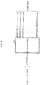
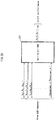
- Fig. 1 is an overview of a DVB-T2 modulator complaint with the DVB-T2 system architecture (fundamental design concept).
- the DVB-T2 modulator 1000 includes an input processer 1010, a bit-interleaved coding and modulation (BICM) encoder 1020, a frame builder 1030, and an OFDM generator 1040.
- BICM bit-interleaved coding and modulation
- the input processor 1010 formats input bit streams relating to a broadcast service into blocks of a predetermined length.
- the BICM encoder 1020 applies BICM encoding based on DVB-T2 to the input.
- the frame builder 1030 assembles transmission frames for transmission in DVB-T2 from the inputs received from the BICM encoder 1020, and the like.
- the OFDM generator 1040 processes the frame structure for DVB-T2 transmission by adding pilots, applying Inverse Fast Fourier Transform, inserting guard intervals to output DVB-T2 transmission signals.
- Non-Patent Literature 1 The BICM based on DVB-T2 is described in Clause 6 of ETSI EN 302 755 (Non-Patent Literature 1).
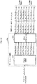
- Fig. 2 is a block diagram of the BICM encoder 1020 included in the DVB-T2 modulator 1000 shown in Fig. 1 .
- the BICM encoder 1020 includes an FEC encoder 1110, a bit interleaver 1120, a bit-to-cell demultiplexer 1130, and a QAM mapper 1140.
- FEC encoder 1110 FEC encoder
- bit interleaver 1120 bit-to-cell demultiplexer
- QAM mapper 1140 QAM mapper
- the procedure for BICM encoding according to DVB-T2 involves the forward-error-correction (FEC) encoding, interleaving the codeword bits resulting from the FEC encoding, demultiplexing the interleaved bits into cell words, and mapping the cell words onto complex QAM (Quadrature Amplitude Modulation) symbols (which are also referred to as cells).
- FEC forward-error-correction
- the FEC encoder 1110 is composed by concatenating a BCH (Bose-Chaudhuri-Hocquenghem) encoder (systematic BCH outer encoder) 1111 and an LDPC (low-density parity check) encoder (systematic LDPC inner encoder) 1112.
- BCH Bit-Chaudhuri-Hocquenghem
- LDPC low-density parity check
- the BCH encoder 1111 generates BCH parity bits by BCH encoding a baseband frame and outputs, to the LDPC encoder 1115, a BCH codeword to which the BCH parity bits are appended. Then, the LDPC encoder 1115 encodes the BCH codeword with LDPC to generate LDPC parity bits and outputs to the bit interleaver 1120 LDPC codeword to which the LDPC parity bits are appended, as shown in Fig. 3 .
- the codeword length of the LDPC codeword (i.e., the number of bits of an LDPC coded block, which may also be referred to as FEC frame) according to the DVB-T2 standard is 64800 bits or 16200 bits.
- the DVB-T2 standard specifies LDPC codes for both codeword lengths. However, only codeword length 16200 is relevant to the present invention as will be explained later.
- the LDPC code provides most of the error-correction capability of the system, while the BCH code reduces the remaining error floor after LDPC decoding.
- the bit interleaver 1120 includes a parity interleaver 1121 and a column-row interleaver 1125.
- the parity interleaver 1121 interleaves the parity bits of the systematic LDPC codeword. Then, the column-row interleaver 1125 interleaves the LDPC codeword bits resulting from the parity interleaving by column-row interleaving.
- the bit-to-cell demultiplexer 1130 demultiplexes the LDPC codeword bits resulting from the bit-interleaving to cell words prior to mapping to QAM constellations. Note that the demultiplexing involves the process equivalent to a permutation of the columns of the interleaver matrix of the column-row interleaver 1125 (a process of rearranging the order of the columns of the interleaver matrix).
- the QAM mapper 1140 maps the cell words onto the QAM constellations.
- the LDPC codes are linear error correction codes for transmitting a message over a noisy transmission channel.
- the LDPC codes are finding increasing use in applications where reliable and highly efficient information transfer over bandwidth or return-channel constrained links in the presence of data-corrupting noise is desired.
- LDPC codes are defined by a sparse parity-check matrix (i.e., a parity-check matrix in which only few entries are ones).
- the LDPC encoder 1115 of DVB-T2 treats the output of the BCH encoder 1111 as an information block and systematically encodes the information block onto an LDPC codeword.
- the task of the LDPC encoder 1115 is to compute the parity bits for every information block, input to the LDPC encoder 1115, i.e. for every BCH codeword.
- the processing of the LDPC encoder 1115 uses the particular codes as listed in tables A.1 through A.6 included in Annex A of the DVB-T2 standard 302.755 (Non-Patent Literature 1).
- bit interleaver 1120 as well as the bit-to-cell demultiplexer 1130 is used between the LDPC encoder 1115 and the QAM mapper 1140.
- bit interleaver 1120 and the bit-to-cell demultiplexer 1130 allow achieving an improved association between the bits of the encoded LDPC codeword and the bits carried by the QAM constellations.
- the different importance levels of the bits of an LDPC codeword results from the fact that not all these bits are involved in the same number of parity-checks, as defined by the parity-check matrix.
- the different importance levels of the bits encoded in a QAM constellation is a fact well known by the person skilled in the art.
- a 16QAM constellation encodes four bits and has two robustness levels.
- a 64QAM constellation encodes six bits and has three robustness levels.
- a 256QAM constellation encodes eight bits and has four robustness levels.
- the column-row interleaver 1125 of the bit interleaver 1120 performs the column-row interleaving process, which is equivalent to a process of serially writing column-wise the data bits received from the parity interleaver 1121 into an interleaver matrix, cyclically shifting (referred to as twisting) each column by a specified number of bits, and serially reading out the bits row-wise.
- the first bit of the LDPC codeword (FEC frame) is written and read out first.
- the write start position of every column is twisted (i.e. cyclically shifted) by the twisting parameter t c according to Table 2.
- the twisting parameter t c of all columns of the interleaver matrix is listed for all relevant constellation sizes (referred to as "modulation" in Table 2) and LDPC codeword lengths N ldpc of an LDPC codeword.
- Fig. 4 shows a process performed by the column-row interleaver 1125, assuming that a long frame with 64800 bits is generated by the FEC encoder 1110 (which includes the BCH encoder 1111 and LDPC encoder 1115) and that a 16QAM constellation is used as the QAM constellation.
- the interleaver matrix has 8100 rows and 8 columns.
- the column-row interleaver 1125 serially writes the data bits, which are received from the parity interleaver 1121, column-wise into an interleaver matrix with twist.
- the write start position of each column is twisted by using the twisting parameter t c shown in Table 2.
- the column-row interleaver 1125 serially reads out the bits row-wise from the interleaver matrix.
- the MSB (most significant bit) of the baseband frame header is written and read out first.
- the "LSB of FEC Frame" in Fig. 4 refers to the LSB (least significant bit) of the FEC frame after column-row interleaving with twist (i.e., column twist interleaving).
- Figs. 5A, 5B , 6A, and 6C show an example of column-row interleaving for LDPC codewords of codeword length 16200 bits, for a number of columns equal to 8 and 12 respectively.
- Figs 5A and 6A are relevant to the writing of bits by the column-row interleaver 1125
- Figs. 5B and 6B are relevant to the reading of bits by the column-row interleaver 1125.
- each smallest square represents one bit of the LDPC codeword
- each black square represents the first bit of the LDPC codeword.
- the arrow indicates the order in which the bits are written into or read out of the interleaver matrix. Note that the process of twisting is not shown in Figs. 5A, 5B , 6A, and 6B .
- the LDPC codeword bits are written in the order of (row 1, column 1), (row 2, column 1), ... (row 2025, column 1), (row 1, column 2), ... (row 2025, column 8), as shown in Fig. 5A , and read out in the order of (row 1, column 1), (row 1, column 2), ... (row 1, column 8), (row 2, column 1), ... (row 2025, column 8), as shown in Fig. 5B .
- each LDPC codeword having been bit-interleaving by the bit interleaver 1120 is first demultiplexed into parallel cell words by the bit-to-cell demultiplexer 1130.
- Each cell word demultiplexed contains as many bits as are encoded in one QAM constellation ( ⁇ MOD ), that is, 2 bits for QPSK (4QAM) constellation, 4 bits for 16QAM constellation, 6 bits for 64QAM constellation, and 8 bits for 256QAM constellation.
- the resulting number of QAM data cells per LDPC codeword (FEC block) of codeword length 16200 bits is therefore 16200/ ⁇ MOD . That is, 8100 cells for QPSK, 4050 cells for 16QAM, 2700 cells for 64QAM, and 2025 cells for 256QAM.
- bit-to-cell demultiplexer 1130 shown in Fig. 2 , with reference to Figs. 7 through 10 .
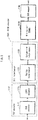
- Fig. 7 illustrates the input and output of the bit-to-cell demultiplexer 1130 shown in Fig. 2 .
- the bit stream from the bit interleaver 1120 is demultiplexed by the bit-to-cell demultiplexer 1130 into sub-bitstreams as shown in Fig. 7 .
- the number of the sub-bitstreams N substreams is two for QPSK (4QAM) constellations and equal with the number of columns of the interleaver matrix in the column-row interleaver 1125 for higher-order constellations (16QAM, 64QAM, 256QAM).
- the demultiplexing also contains a bit permutation step (which is conceptually equivalent to a permutation of the columns of the interleaver matrix in the column-row interleaver).
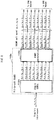
- the bit-to-cell demultiplexer 1130A shown in Fig. 8 includes a simple demultiplexer 1131A and a DEMUX permutator 1135A.
- the simple demultiplexer 1131A receives one bit stream (v 0 , v 1 , v 2 , ...) from the bit interleaver 1120 and demultiplexes the received bit stream into 8 sub-bitstreams, namely the first sub-bitstream (v 0,0 , v 0,1 , v 0,2 , ...) to the eighth sub-bitstream (v 7,0 , v 7,1 , v 7,2 , ).
- the simple demultiplexer 1131A then outputs the resulting 8 sub-bitstreams to the DEMUX permutator 1135A. Note that the output bits v i,j of the simple demultiplexer 1131A correspond to the input bits v i+8 ⁇ j to the simple demultiplexer 1131A.
- the DEMUX permutator 1135A receives the 8 sub-bitstreams from the simple demultiplexer 1131A, permutes the 8 sub-bitstreams received, and outputs 8 sub-bitstreams obtained as a result of the permutation.
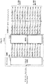
- the bit-to-cell demultiplexer 1130B shown in Fig. 9 includes a simple demultiplexer 1131B and a DEMUX permutator 1135B.
- the simple demultiplexer 1131B receives one bit stream (vo, v 1 , v 2 , ...) from the bit interleaver 1120 and demultiplexes the received bit stream into 12 sub-bitstreams, namely the first sub-bitstream (v 0,0 , v 0,1 , v 0,2 , ...) to the twelfth sub-bitstream (v 11,0 , v 11,1 , v 11,2 , ).
- the simple demultiplexer 1131B then outputs the resulting 12 sub-bitstreams to the DEMUX permutator 1135B. Note that the output bits v i,j of the simple demultiplexer 1131B correspond to the input bits v i+12 ⁇ j to the simple demultiplexer 1131B.
- the DEMUX permutator 1135B receives the 12 sub-bitstreams from the simple demultiplexer 1131B, permutes the 12 sub-bitstreams received, and outputs 12 sub-bitstreams obtained as a result of the permutation.
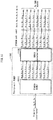
- the bit-to-cell demultiplexer 1130C shown in Fig. 10 includes a simple demultiplexer 1131C and a DEMUX permutator 1135C.
- the simple demultiplexer 1131C receives one bit stream (vo, v 1 , v 2 , ...) from the bit interleaver 1120 and demultiplexes the received bit stream into 8 sub-bitstreams, namely the first sub-bitstream (v 0,0 , v 0,1 , v 0,2 , ...) to the eighth sub-bitstream (v 7,0 , v 7,1 , v 7,2 , ).
- the simple demultiplexer 1131C then outputs the resulting 8 sub-bitstreams to the DEMUX permutator 1135C. Note that the output bits v i,j of the simple demultiplexer 1131C correspond to the input bits v i+8 ⁇ j to the simple demultiplexer 1131C.
- bit-to-cell demultiplexing by the bit-to-cell demultiplexer 1130 is defined as a mapping of the bit-interleaved input bits b di onto the output bits b e,do , where:
- the DVB-T2 standard defines bit-to-cell demultiplexing processes for all the available LDPC code rates in DVB-T2 (1/2, 3/5, 2/3, 3/4, 4/5, and 5/6), and constellation modes (QPSK, 16QAM, 64QAM and 256 QAM) (see Tables 13(a, b, c) in Clause 6.2.1 of Non-Patent Literature 1: EN 302.755 v1.2.1). These parameters shown in Tables 13(a, b, c) define permutations of the input bits to the output bits of a sub-bitstream.
- This permutation rule is optimized for code rates 1/2, 3/4, 4/5, and 5/6, such that the error rate at the output of the LDPC decoder in the receiver is minimized.
- the first ⁇ MOD N substreams /2 bits [bo,do ... b Nsubstreams/2-1,do ] form the first of a pair of output cell words [y 0,2do ... y ⁇ mod-1, 2do ] and the remaining output bits [bNsubstreams/2, do ... b Nsubstreams-1,do ] form the second output cell word [y 0,2do+1 ... Y ⁇ mod-1,2do+1 ] fed to the QAM mapper.
- the number of cell words involved in a DEMUX permutation by the DEMUX permutator is either one (for 256QAM) or two (for 16QAM and 64QAM).
- the DEMUX permutation is conceptually equivalent to a permutation of the columns in the interleaver matrix of the column-row interleaver of the bit-interleaver.
- each cell word output from the bit-to-cell demultiplexer is modulated according to a particular mapping constellation (such as QPSK, 16QAM, 64QAM or 256QAM).
- a particular mapping constellation such as QPSK, 16QAM, 64QAM or 256QAM.
- the constellations and the details of the Gray mapping applied to the bits according to DVB-T2 are illustrated in Figs. 11, 12 , 13 and 14 .
- DVB-NGH A next-generation digital broadcast standard for handheld reception is currently under development in the DVB standardization body under the name DVB-NGH.
- This DVB-NGH standard will use the same BICM structure as explained above, which comprises FEC encoding, bit-interleaving, demultiplexing, and QAM constellation mapping.
- two additional LDPC code rates (namely 7/15 and 8/15) are added.
- the same QAM constellations as DVB-T2 will remain, i.e. QPSK (4QAM) constellation, 16QAM constellation, 64QAM constellation, and 256QAM constellation.
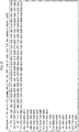
- Figs. 25 and 26 show the addresses of the parity bit accumulators for the LDPC code having a codeword length of 16200 bits with the code rate of 7/15.
- Fig. 26 shows the addresses of the parity bit accumulators for the LDPC code having a codeword length of 16200 bits with the code rate of 8/15.
- the parallel or cyclic factor has the same value 360 like in DVB-S2.
- Non-Patent Literature 3 Since the disclosure of Figs. 25 and 26 comply with the contents of Non-Patent Literature 3, it is naturally assumed that the LDPC codes are readily understandable to those skilled in the art based on Figs. 25 and 26 . Yet, the following describes an example in which the contents of Non-Patent Literature 3 (Clause 5.3.2 and Annexes B and C of ETSI EN 302 307 V1.2.1 (2009, April )) are applied.
- the LDPC encoder systematically encodes an information block (output of the BCH encoder) i of size K ldpc into an LDPC codeword c of size of N ldpc , as in Equation 1 below.
- i i 0 i 1 ⁇ i K ldpc ⁇ 1
- the task of the LDPC encoder is to compute the N ldpc - K ldpc parity bits for every block of K ldpc information bits.
- parity bits are initialized as shown in Equation 2.
- the first information bit io is accumulated at each parity bit address specified in the first row of Fig. 25 . More specifically, the operations of Equation 3 are performed.
- i m is accumulated at each parity bit address ⁇ x + (m mod 360) ⁇ q ⁇ mod (N ldpc - K ldpc ).
- x denotes the address of the parity bit accumulator corresponding to the first bit i 0
- q is a constant dependent on the code rate 7/15, which in this case is 24.
- the addresses of the parity bit accumulators are given in the second row of Fig. 25 .
- the addresses of the parity bit accumulators are given by ⁇ x + (m mod 360) ⁇ q ⁇ mod (N ldpc - K ldpc ).
- x denotes the address of the parity bit accumulator for the 360 th information bit i 360 , i.e. the entries in the second row of Fig. 25 .
- p i p i ⁇ p i ⁇ 1
- i 1,2 , ⁇ , N ldpc ⁇ K ldpc ⁇ 1
- ⁇ stands for XOR.
- Various embodiments of the present invention provide a system for processing bit signals to be transmitted before they are input to a QAM mapper. Further embodiments of the present invention provides a system for processing bit signals received from the QAM demapper (for performing the inverse process of the process conducted on the transmission bits at the transmitting side).
- a digital signal comprising e.g. an audio and/or video signal
- a digital signal is to be transmitted/broadcast from transmitters and is intended to be received by receivers, such as mobile terminals.
- Fig. 15 is a block diagram of the BICM encoder according to the embodiment of the present invention.
- the BICM encoder shown in Fig. 15 basically corresponds to the BICM encoder according to DVB-T2 and described in detail in the "Findings by Present Inventor Leading to the Invention" section with reference to Figs. 1 through 14 .
- the BICM encoder 100 shown in Fig. 15 includes an FEC encoder 110, a bit interleaver 120, a bit-to-cell demultiplexer 130, and a QAM mapper 140.
- the FEC encoder 110 includes a BCH encoder 111 and an LDPC encoder 115.
- the contents described in the "Supplement 2" section is also applicable to a system in which the BCH encoder 111 upstream of the LDPC encoder 115 is omitted or replaced with an encoder for different code.
- a digital signal such as an audio and/or a video signal, consisting of information bits is input.
- the BCH encoder 111 generates BCH parity bits by BCH encoding a baseband frame input thereto and outputs a BCH codeword to which the BCH parity bits are appended to the LDPC encoder 115.
- the LDPC encoder 115 encodes the BCH codeword with a specific LDPC code to generate LDPC parity bits.
- the LDPC code used here in this embodiment is an LDPC code having a codeword length of 16200 bits with code rate 7/15 according to Fig. 25 or an LDPC code having a codeword length of 16200 bits with code rate 8/15 according to Fig. 26 .
- the encoded 16200-bit LDPC codewords are input to the bit interleaver 120 that performs parity interleaving and column twist interleaving as explained in the DVB-T2 standard, Clause 6.1.3.
- the bit interleaver 120 includes a parity interleaver 121 and a column-row interleaver 125.
- the parity interleaver 121 performs parity interleaving to permute the order of parity bits of the 16200-bit LDPC codeword and outputs the resulting LDPC codeword to the column-row interleaver 125.
- the parity interleaver 121 performs the operations of Equation 5.
- K ldpc denotes the number of information bits of an LDPC codeword and information bits are not interleaved.
- the column-row interleaver 125 performs column twist interleaving (column-row interleaving with twist) on the parity interleaved 16200-bit LDPC codeword received from the parity interleaver 121 and outputs the 16200-bit LDPC codeword resulting from the column twist interleaving to the bit-to-cell demultiplexer 130.
- the interleaver matrix used by the column-row interleaver 125 for column twist interleaving is a matrix whose number of entries (a value obtained by multiplying the number of columns by the number of rows) is 16200, which is equal to the number of LDPC codeword bits. That is, the dimensions of the interleaver matrix differ (i.e., the number of columns as well as the number of rows differ) depending on the type of modulation being used in the QAM mapper 140.
- the column-row interleaver 125 serially writes column-wise the 16200 data bits (parity interleaved LDPC codeword), which is output from the parity interleaver 121, with twist.
- the write start position of each column is twisted by using the column twisting parameters t c shown in Table 2.
- the column-row interleaver 125 serially reads out the 16200 bits from the interleaver matrix row-wise (see Figs. 4 , 5 , and 6 for reference).
- the embodiments of the present invention in particular the various permutation rules used by the bit-to-cell demultiplexer, can be applied to column twisting parameters not listed in Table 2. Furthermore, though column twist interleaving is part of the DVB-T2 system, and thus will probably be part of the DVB-NGH system, the embodiments of the present invention can also be applied to a column-row interleaving process without column twist.
- the bit-to-cell demultiplexer 130 permutes the 16200-bit LDPC codewords according to the various examples of the embodiment of the present invention.
- the permutation processing, and in particular the permutation rules which are to be applied, depend on: (1) the LDPC code used by the LDPC encoder 115, further characterized by its codeword length and the code rate; and on (2) the QAM constellation size used by the QAM mapper 140.
- the bit-to-cell demultiplexer 130 demultiplexes the bits of the bit-interleaved LDPC codeword, which is input from the bit interleaver 120, into parallel cell words. Then, the bit-to-cell demultiplexer 130 performs the permutation after which the permuted cell words are mapped into constellation symbols according to the specified QAM mapping.
- the number of output QAM data cells (the number of cell words) and the effective number of bits per cell word ⁇ MOD is the same as for DVB-T2 explained in the "Findings by Present Inventor Leading to the Invention" section of this specification. Particularly, there are 8100 cells for QPSK (4QAM), 4050 cells for 16QAM, 2700 cells for 64QAM, and 2025 cells for 256 QAM.
- bit-to-cell demultiplexer 130 shown in Fig. 15 , with reference to Figs. 16 through 19 .
- Fig. 16 illustrates the input and output of the bit-to-cell demultiplexer 130 shown in Fig. 15 .
- the bitstream from the bit interleaver 120 is demultiplexed by the bit-to-cell demultiplexer 130 into sub-bitstreams as shown in Fig. 16 .
- the number of sub-bitstreams N substreams is the same as for DVB-T2.
- the number of sub-bitstreams N substreams is 2 for QPSK (4QAM) constellations, 8 for 16QAM constellation, 12 for 64QAM constellation, and 8 for 256QAM constellation.
- bit-to-cell demultiplexing After the bit-to-cell demultiplexing, a permutation is carried out by a particular interleaving of input bits b di onto the output bits b e,do .
- do di div N substreams
- div is a function that returns an integer portion of the result obtained by dividing di by N substreams .
- e is the demultiplexed bitstream number (0 ⁇ e ⁇ N substreams ) (i.e., the number identifying the sub-bitstream output from the bit-to-cell demultiplexer 130).
- v di is the input bits to the bit-to-cell demultiplexer 130, and di is the input bit number.
- b e,do is the output bits from the bit-to-cell demultiplexer 130, and do is the bit number of a given sub-bitstream output from the bit-to-cell demultiplexer 130.
- the bit-to-cell demultiplexer 130A shown in Fig. 17 includes a simple demultiplexer 131A and a DEMUX permutator 135A.
- the simple demultiplexer 131A receives one bit stream (vo, v 1 , v 2 , ...) from the bit interleaver 120 and demultiplexes the received bit stream into 8 sub-bitstreams, namely the first sub-bitstream (v 0,0 , v 0,1 , v 0,2 , ...) to the eighth sub-bitstream (v 7,0 , v 7,1 , v 7,2 , ).
- the simple demultiplexer 131A then outputs the resulting 8 sub-bitstreams to the DEMUX permutator 135A. Note that the output bits v i,j of the simple demultiplexer 131A correspond to the input bits v i+8 ⁇ j to the simple demultiplexer 131A.
- the DEMUX permutator 135A receives the 8 sub-bitstreams from the simple demultiplexer 131A, permutes the 8 sub-bitstreams received, and outputs 8 sub-bitstreams obtained as a result of the permutation.
- the bit-to-cell demultiplexer 130B shown in Fig. 18 includes a simple demultiplexer 131B and a DEMUX permutator 135B.
- the simple demultiplexer 131B receives one bit stream (vo, v 1 , v 2 , ...) from the bit interleaver 120 and demultiplexes the received bit stream into 12 sub-bitstreams, namely the first sub-bitstream (v 0,0 , v 0,1 , v 0,2 , ...) to the twelfth sub-bitstream (v 11,0 , v 11,1 , v 11,2 , ).
- the simple demultiplexer 131B then outputs the resulting 12 sub-bitstreams to the DEMUX permutator 135B. Note that the output bits v i,j of the simple demultiplexer 131B correspond to the input bits v i+12 ⁇ j to the simple demultiplexer 131B.
- the DEMUX permutator 135B receives the 12 sub-bitstreams from the simple demultiplexer 131B, permutes the 12 sub-bitstreams received, and outputs 12 sub-bitstreams obtained as a result of the permutation.
- the bit-to-cell demultiplexer 130C shown in Fig. 19 includes a simple demultiplexer 131C and a DEMUX permutator 135C.
- the simple demultiplexer 131C receives one bit stream (vo, v 1 , v 2 , ...) from the bit interleaver 120 and demultiplexes the received bit stream into 8 sub-bitstreams, namely the first sub-bitstream (v 0,0 , v 0,1 , v 0,2 , ...) to the eighth sub-bitstream (v 7,0 , v 7,1 , v 7,2 , ).
- the simple demultiplexer 1131C then outputs the resulting 8 sub-bitstreams to the DEMUX permutator 135C. Note that the output bits v i,j of the simple demultiplexer 131C correspond to the input bits v i+8 ⁇ j to the simple demultiplexer 131C.
- the cell words obtained as a result of the processing by the bit-to-cell demultiplexer 130 are serially output to the QAM mapper 140 shown in Fig. 15 .
- the QAM mapper 140 maps the cell words (the output of the bit-to-cell demultiplexer) to the constellation symbols according to the particular one of 16QAM, 64QAM and 256QAM modulation of Fig. 12 , 13 and 14 , i.e. according to the bit labeling used in the DVB-T2 standard.
- demultiplexing parameters will be presented according to various embodiments of the invention for applying permutation schemes for different LDPC codes and different modulation modes.
- the following permutation is applied in the DEMUX permutator of the bit-to-cell demultiplexer, according to Figs. 17 through 19 , as being part of Fig. 15 .
- the following describes the processing performed by the bit-to-cell demultiplexer 130B shown in Fig. 18 , according to one example of the embodiment of the present invention.
- This example is directed to the case where the LDPC encoder 115 uses the LDPC code having a codeword length of 16200 and code rate 7/15 as shown in Fig. 25 , and the QAM mapper 140 uses a 64QAM modulation as the modulation scheme.
- the permutation in the DEMUX permutator 135B is performed as depicted in Fig. 18 on the 12 bits of a row of the interleaver matrix that is read out row-wise and then demultiplexed according to Fig. 18 .
- the DEMUX permutator 135B permutes the 12 input bits v di (v di,do ) to the 12 output bits b e (b e,do ) according to the following permutation rule.
- the two cell words are extracted for each b e .
- the two bit-to-cell words y 0 -y 5 are output to the QAM mapper 140 of the 64QAM type for being mapped to two consecutive modulation symbols.
- the following describes the processing performed by the bit-to-cell demultiplexer 130C shown in Fig. 19 , according to another example of the embodiment of the present invention.
- This example is directed to the case where the LDPC encoder 115 uses the LDPC code having a codeword length of 16200 and code rate 7/15 as shown in Fig. 25 , and the QAM mapper 140 uses a 256QAM modulation as the modulation scheme.
- the permutation in the DEMUX permutator 135C is performed as depicted in Fig. 19 on the 8 bits of a row of the interleaver matrix that is read out row-wise and then demultiplexed according to Fig. 19 .
- the DEMUX permutator 135C permutes the 8 input bits v di (v di,do ) to the 8 output bits b e (b e,do ) according to the following permutation rule.
- bit-to-cell word y 0 -y 7 is output to the QAM mapper 140 of the 256QAM type for being mapped to two consecutive modulation symbols.
- the following describes the processing performed by the bit-to-cell demultiplexer 130B shown in Fig. 18 , according to yet another example of the embodiment of the present invention.
- This example is directed to the case where the LDPC encoder 115 uses the LDPC code having a codeword length of 16200 and code 8/15 as shown in Fig. 26 , and the QAM mapper 140 uses a 64QAM modulation as the modulation scheme.
- the permutation in the DEMUX permutator 135B is performed as depicted in Fig. 18 on the 12 bits of a row of the interleaver matrix that is read out row-wise and then demultiplexed according to Fig. 18 .
- the DEMUX permutator 135B permutes the 12 input bits v di (v di,do ) to the 12 output bits b e (b e,do ) according to the following permutation rule.
- the two cell words are extracted for each b e .
- the two bit-to-cell words y 0 -y 5 are output to the QAM mapper 140 of the 64QAM type for being mapped to two consecutive modulation symbols.
- BICM decoder is provided in a receiver.
- apparatuses having the BICM decoder according to this embodiment include handheld devices, mobile phones, tablet PCs, notebooks, televisions, etc.
- the processing by the BICM decoder provided in the receiver will basically be the reverse of the above-explained processing performed by the BICM encoder provided in the transmitter.
- complex cells will be demodulated according to the constellation mapping (QPSK, 16QAM, 64QAM, 256QAM) to determine the transmitted bit-to-cell words.
- One cell word in the case of 256QAM
- two cell words in the cases of 16QAM and 64QAM
- the resulting bit stream is subjected to column-row deinterleaving by a column-row deinterleaver, as well as to parity deinterleaving by a parity deinterleaver. Note that bits deinterleaved by the parity deinterleaver are parity bits only.
- the output bits of the parity deinterleaver are decoded by the LDPC decoder, which is in concordance with the transmitting side LDPC coding. Then, a stream of bits resulting from the decoding is output.
- Fig. 20 is a block diagram of the BICM decoder according to the embodiment of the present invention.
- the BICM decoder 300 shown in Fig. 20 includes a QAM demapper 310, a cell-to-bit multiplexer 320, a bit deinterleaver 330, and an FEC decoder 340.
- the QAM demapper 310 demodulates complex cells according to a particular modulation mode (such as 16QAM, 64QAM or 256QAM) and outputs the resulting cell words to the cell-to-bit multiplexer 320.
- a particular modulation mode such as 16QAM, 64QAM or 256QAM
- the cell words corresponding to 16QAM, 64QAM, and 256QAM comprise 4, 6 and 8 bits, respectively.
- the QAM demodulation performed by the QAM demapper 310 is in accordance with the QAM modulation performed by the QAM mapper 140 provided in the transmitter. If the QAM mapper 140 of the transmitter performs 16QAM modulation according to the DVB-T2 labeling of Fig. 12 , the QAM demapper 310 performs demodulation based on the same 16QAM of Fig. 12 , to demodulate each modulation symbol (complex cell) into a cell word of 4 bits. The same applies to the all the QAM modulations according to Figs. 11 , 13 , and 14 .
- the cell-to-bit multiplexer 320 includes a permutation block and a multiplexing block.
- the permutation block processes the demodulated bits according to a permutation rule depending on the modulation mode and the LDPC code used in the transmitting side (and conversely in the receiving side).
- Fig. 21 illustrates the input and output of the cell-to-bit multiplexer 320 shown in Fig. 20 .
- the cell words y consisting of input bits b are input to the cell-to-bit multiplexer 320 and are permuted by the cell-to-bit multiplexer 320 to generate output words v.
- Fig. 22 is a block diagram of the cell-to-bit multiplexer for 16QAM constellation.
- the cell-to-bit multiplexer 320A shown in Fig. 22 includes an inverse DEMUX permutator 321A and a simple multiplexer 325A.
- the inverse DEMUX permutator 321A receives 8 sub-bitstreams (8 bits b 0 -b 7 which form two cell words of 4 bits y 0 -y 3 ), which are input from the QAM demapper 140 for 16QAM.
- the inverse DEMUX permutator 321A performs a permutation on the received 8 sub-bitstreams (i.e., a permutation to restore the order of sub-bitstreams that is before the permutation by the DEMUX permutator 135A in the transmitting side) and outputs the resulting 8 sub-bitstreams to the simple multiplexer 325A.
- the simple multiplexer 325A multiplexes the 8 sub-bitstreams obtained as a result of the permutation to a single bit-stream of 16200 bits to output.
- the resulting output bits v i+8 ⁇ j of the simple multiplexer 325A correspond to the input bits v i,j of the simple multiplexer 325A.
- Fig. 23 is a block diagram of the cell-to-bit multiplexer for 64QAM constellation.
- the cell-to-bit multiplexer 320B shown in Fig. 23 includes an inverse DEMUX permutator 321B and a simple multiplexer 325B.
- the inverse DEMUX permutator 321B receives 12 sub-bitstreams (12 bits b 0 -b 11 which form two cell words of 6 bits y 0 -y 5 ), which are input from the QAM demapper 140 for 64QAM.
- the inverse DEMUX permutator 321B performs a permutation on the received 12 sub-bitstreams (i.e., a permutation to restore the order of sub-bit streams that is before the permutation by the DEMUX permutator 135B in the transmitting side) and outputs the resulting 12 sub-bitstreams to the simple multiplexer 325B.
- the simple multiplexer 325B multiplexes the 12 sub-bitstreams obtained as a result of the permutation to a single bit-stream of 16200 bits to output.
- the resulting output bits v i+12 ⁇ j of the simple multiplexer 325B correspond to the input bits v i,j of the simple multiplexer 325B.
- Fig. 24 is a block diagram of the cell-to-bit multiplexer for 256QAM constellation.
- the cell-to-bit multiplexer 320C shown in Fig. 24 includes an inverse DEMUX permutator 321C and a simple multiplexer 325C.
- the inverse DEMUX permutator 321C receives 8 sub-bitstreams (8 bits b 0 -b 7 which form one cell word of 8 bits y 0 -y 7 ), which are input from the QAM demapper 140 for 256QAM.
- the inverse DEMUX permutator 321C performs a permutation on the received 8 sub-bitstreams (i.e., a permutation to restore the order of the substreams that is before the permutation by the DEMUX permutator 135C in the transmitting side) and outputs the resulting 8 sub-bitstreams to the simple multiplexer 325C.
- the simple multiplexer 325C multiplexes the 8 sub-bitstreams obtained as a result of the permutation to a single bit-stream of 16200 bits to output.
- the resulting output bits v i+8 ⁇ j of the simple multiplexer 325C correspond to the input bits v i,j of the simple multiplexer 325C.
- the bit deinterleaver 330 includes a column-row deinterleaver 331 and a parity deinterleaver 335.
- the column-row deinterleaver 331 receives a bit stream composed of 16200 bits v (vo, v 1 , v 2 ...) from the cell-to-bit multiplexer 320 (320A through 320C).
- the column-row deinterleaver 331 performs column-row deinterleaving with twist (column twist deinterleaving) on the 16200 input bits received. More specifically, the column-row deinterleaver 331 serially writes the 16200 input bits row-wise into a deinterleaver matrix, and then serially reads out the 16200 bits column-wise from the deinterleaver matrix with twist. In the process of twisting, the read start position of each column is twisted by using the twisting parameter t c shown in Table 2.
- the dimensions of the deinterleaver matrix depend on the constellation size used in the demodulation process by the QAM demapper 310 and the codeword length of the LDPC code used in the LDPC demodulation by the LDPC decoder 341.
- the number of columns of the deinterleaver matrix is 8 for 16QAM, resulting in 2025 rows.
- 64QAM the number of columns is 12, resulting in 1350 rows.
- 256QAM the number of columns is 8, resulting in 2025 rows.
- the values of the twisting parameter t c used by the column-row deinterleaver 331 are the same as the values of twisting parameter t c used by the column-row interleaver 125.
- the column-row interleaver 125 may perform column-row interleaving without twist. In such a case, the column-row deinterleaver 331 performs column-row deinterleaving without twist.
- the parity deinterleaver 335 performs parity deinterleaving to permute the order of the LDPC parity bits out of the bits input from the column-row deinterleaver 331 (i.e., a to restore the order of the bits before the permutation by the parity interleaver 121 in the transmitting side) (see Equation 5).
- the FEC decoder 340 includes the LDPC decoder 341 and a BCH decoder 345. Note that the contents described in the "Supplement 2" section is also applicable to a system in which the BCH decoder 345 downstream of the LDPC decoder 341 is omitted or replaced with a decoder for different code.
- the LDPC decoder 341 performs the demodulation using the LDPC code used by the LDPC encoder 115 of the transmitter shown in Fig. 15 . More specifically, an LDPC code having a codeword length of 16200 bits with code rate 7/15 according to Fig. 25 or an LDPC code having a codeword length of 16200 bits with code rate 8/15 according to Fig. 26 is used in the demodulation.
- the BCH decoder 345 performs a BCH decoding process on the data resulting from the demodulation by the LDPC decoder 341.
- Case A The LDPC decoder uses an LDPC code having a codeword length of 16200 bits and code rate 7/15 as shown in Fig. 25 , and the QAM demapper performs a 64QAM demodulation.
- Case B The LDPC decoder uses an LDPC code having a codeword length of 16200 bits and code rate 7/15 as shown in Fig. 25 , and the QAM demapper performs a 256QAM demodulation.
- Case C The LDPC decoder uses an LDPC code having a codeword length of 16200 bits and code rate 8/15 as shown in Fig. 26 , and the QAM demapper uses a 64QAM demodulation.
- the following describes the processing performed by the cell-to-bit multiplexer 320B shown in Fig. 23 , according to one example of the embodiment of the present invention. Note that this example is directed to the case where the LDPC decoder 341 uses the uses the LDPC code having a codeword length of 16200 and code rate 7/15 as shown in Fig. 25 , and the QAM demapper 310 performs 64QAM demodulation.
- the permutation by the inverse DEMUX permutator 321B is performed as illustrated in Fig. 23 on 12 bits that are serially input from the QAM demapper 310.
- the inverse DEMUX permutator 321B permutes two cell words composed of 12 input bits b e (b e,do ) to the 12 output bits v di (v di,do ) according to the following permutation rule.
- the thus permuted bits v are multiplexed by the simple multiplexer 325B.
- the following describes the processing performed by the cell-to-bit multiplexer 320C shown in Fig. 24 , according to another example of the embodiment of the present invention. Note that this embodiment is directed to the case where the LDPC decoder 341 uses the uses the LDPC code having a codeword length of 16200 and code rate 7/15 as shown in Fig. 25 , and the QAM demapper 310 performs 256QAM demodulation.
- the permutation by the inverse DEMUX permutator 321B is performed as illustrated in Fig. 24 on 8 bits that are serially input from the QAM demapper 310.
- the inverse DEMUX permutator 321C permutes one cell word composed of 8 input bits b e (b e,do ) to the 8 output bits v di (v di,do ) according to the following permutation rule.
- the thus permuted bits v are multiplexed by the simple multiplexer 325C.
- the following describes the processing performed by the cell-to-bit multiplexer 320B shown in Fig. 23 , according to yet another example of the embodiment of the present invention. Note that this example is directed to the case where the LDPC decoder 341 uses the uses the LDPC code having a codeword length of 16200 and code rate 8/15 as shown in Fig. 26 , and the QAM demapper 310 performs 64QAM demodulation.
- the permutation by the inverse DEMUX permutator 321B is performed as illustrated in Fig. 23 on 12 bits that are serially input from the QAM demapper 310.
- the inverse DEMUX permutator 321B permutes two cell words composed of 12 input bits b e (b e,do ) to the 12 output bits v di (v di,do ) according to the following permutation rule.
- the thus permuted bits v are multiplexed by the simple multiplexer 325B.
- the present invention is not limited to the specific embodiments described above. Provided that the aims of the present invention and accompanying aims are achieved, other variations are also possible, such as the following.
- the present invention is applicable to a bit-to-cell demultiplexer in a bit-interleaved coding and modulation system used for low-density parity codes, and also to a bit-to-cell demultiplexer corresponding to such a cell-to-bit multiplexer.
Description
- The present invention relates to a method for processing a digital signal in a transmitting side, and in particular to bit permutation patterns applied to bits before being input to the mapper. Furthermore, the present invention relates to a method for processing a digital signal in a receiving side, and in particular to bit permutation patterns applied to bits after being output by the demapper. Additionally, the present invention relates to a transmitter and a receiver for performing the methods.
- In recent years, transmitters are provided with a bit-interleaved coding and modulation (BICM) encoder (see, Non-Patent
Literature 1, for example). - A BICM encoder performs the following steps, for example.
- (1) Encoding data blocks by using a BCH (Bose-Chaudhuri-Hocquenghem) code as an outer code and a Low-Density Parity-Check (LDPC) code as an inner code, for example.
- (2) Applying bit-interleaving, which involves parity interleaving and column-row interleaving, to the codeword bits obtained as a result of the encoding.
- (3) Demultiplexing the bit-interleaved codeword to obtain cell words. The demultiplexing includes processing equivalent to a permutation of the columns of an interleaver matrix used in the column-row interleaving when the type of modulation being used is 16QAM, 64QAM or 256QAM, for example.
- (4) Mapping the cell words onto constellations.
-
- [Non-Patent Literature 1]
ETSI EN 302 755 V1.2.1 (DVB-T2 standard) - [Non-Patent Literature 2]
"New 16k LDPC codes for NGH" by Makiko Kan, with filename: "TM-NGH580_NGH_sony_New_16k_Codes.pdf", document-ID TM-H1115 and published on - [Non-Patent Literature 3]
ETSI EN 302 307 V1.2.1 (DVB-T2 standard) - Document "TM-NGH643_20110120_sony_New_16k_Codes2.pdf" titled "Digital Video Broadcasting (DVB); Next Generation broadcasting system to Handheld, physical layer specification (DVB-NGH)" v.1.1.1 of the DVB Organization of February 16, 2011 discloses a next generation baseline transmissions system for digital terrestrial television broadcasting to handheld terminals. It specifies the channel coding/modulation system intended for digital television services and generic data streams.
WO 2009/109830 A1 discloses methods for digital signaling processing based on LDPC codes with code rate of 3/5 in combination with QAM modulation (16, 64 or 256 QAM). A bit permutation is carried out prior to the QAM constellation mapping fuction. - The reception performance of a receiver can be improved by appropriately optimizing the rules of permutations (including the bit-interleaving numbered (2) above and the permutation carried out in the demultiplexing numbered (3) above) applied to the LDPC codeword bits prior to mapping to be suitable for the LDPC code and constellation used by the transmitter and receiver.
- The present invention aims to provide a transmission processing method and reception processing method according to which the permutation rules applied to the LDPC codeword bits prior to being mapped are optimized for the LDPC codes and constellations used by the transmitter and receiver, thereby improving the reception performance of the receiver. The present invention also aims to provide a transmitter and receiver executing the transmission processing method and reception processing method, respectively.
- In order to achieve the above aims, the inventions according to the independent claims are provided. Further aspects of the present application that are not covered by the claims are to be understood as examples useful for better understanding of the invention.
- According to the transmission processing method described above, the permutation rules to be applied to the LDPC codeword bits prior to being mapped are optimized for the LDPC codes and constellations used by the transmitter and receiver, which is advantageous to improve the reception performance of the receiver.
-
-
Fig. 1 is an overview of a DVB-T2 modulator. -
Fig. 2 is a block diagram of the BICM encoder shown inFig. 1 . -
Fig. 3 shows an LDPC codeword, composed of a baseband frame, BCH parity part, and LDPC parity part. -
Fig. 4 illustrates the working principle of column-row interleaving with twist, carried out by the column-row interleaver shown inFig. 2 . -
Fig. 5A illustrates a write process performed by a column-row interleaver having 8 columns to write bits of an LDPC codeword with a codeword length of 16200 bits, andFig. 5B illustrates a read process performed by the column-row interleaver to read the bits of the LDPC codeword written in the process illustrated inFig. 5A . -
Fig. 6A illustrates a write process performed by a column-row interleaver having 12 columns to write bits of an LDPC codeword with a codeword length of 16200 bits, andFig. 6B illustrates a read process performed by the column-row interleaver to read the bits of the LDPC codeword written in the process illustrated inFig. 6A . -
Fig. 7 illustrates the input and output of the bit-to-cell demultiplexer shown inFig. 2 . -
Fig. 8 is a block diagram of a bit-to-cell demultiplexer for 16QAM constellation. -
Fig. 9 is a block diagram of a bit-to-cell demultiplexer for 64QAM constellation. -
Fig. 10 is a block diagram of a bit-to-cell demultiplexer for 256QAM constellation. -
Fig. 11 shows a particular constellation mapping for QPSK applicable in DVB-T2 for transmission and reception of data. -
Fig. 12 shows a particular constellation mapping for 16QAM applicable in DVB-T2 for transmission and reception of data. -
Fig. 13 shows a particular constellation mapping for 64QAM applicable in DVB-T2 for transmission and reception of data. -
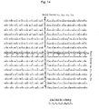
Fig. 14 shows a particular constellation mapping for 256QAM applicable in DVB-T2 for transmission and reception of data. -
Fig. 15 is a block diagram of a BICM encoder according to an embodiment of the present invention. -
Fig. 16 illustrates the input and output of the bit-to-cell demultiplexer shown inFig. 15 . -
Fig. 17 is a block diagram of a bit-to-cell demultiplexer for 16QAM constellation. -
Fig. 18 is a block diagram of a bit-to-cell demultiplexer for 64QAM constellation. -
Fig. 19 is a block diagram of a bit-to-cell demultiplexer for 256QAM constellation. -
Fig. 20 is a block diagram of a BICM decoder according to an embodiment of the present invention. -
Fig. 21 illustrates the input and output of the cell-to-bit multiplexer shown inFig. 20 . -
Fig. 22 is a block diagram of a cell-to-bit multiplexer for 16QAM constellation. -
Fig. 23 is a block diagram of a cell-to-bit multiplexer for 64QAM constellation. -
Fig. 24 is a block diagram of a cell-to-bit multiplexer for 256QAM constellation. -
Fig. 25 shows the LDPC code for a codeword length of 16200 bits andcode rate 7/15. -
Fig. 26 shows the LDPC code for a codeword length of 16200 bits andcode rate 8/15. - DBV-T2 (Digital Video Broadcasting - Second Generation Terrestrial) (ETSI EN 302 755: Non-Patent Literature 1) is improvement of DVB-T, which is the standard for television, and describes a second generation baseline transmission system for digital terrestrial television. More specifically, ETSI EN 302 755 (Non-Patent Literature 1) describes the details of the channel coding/modulation system intended for digital television services and generic data streams.
-
Fig. 1 is an overview of a DVB-T2 modulator complaint with the DVB-T2 system architecture (fundamental design concept). The DVB-T2 modulator 1000 includes aninput processer 1010, a bit-interleaved coding and modulation (BICM)encoder 1020, aframe builder 1030, and anOFDM generator 1040. - The
input processor 1010 formats input bit streams relating to a broadcast service into blocks of a predetermined length. TheBICM encoder 1020 applies BICM encoding based on DVB-T2 to the input. Theframe builder 1030 assembles transmission frames for transmission in DVB-T2 from the inputs received from theBICM encoder 1020, and the like. TheOFDM generator 1040 processes the frame structure for DVB-T2 transmission by adding pilots, applying Inverse Fast Fourier Transform, inserting guard intervals to output DVB-T2 transmission signals. - The BICM based on DVB-T2 is described in Clause 6 of ETSI EN 302 755 (Non-Patent Literature 1).
- The following describes the details of the
BICM encoder 1020 shown inFig. 1 , with reference toFig. 2 . -
Fig. 2 is a block diagram of theBICM encoder 1020 included in the DVB-T2 modulator 1000 shown inFig. 1 . - The
BICM encoder 1020 includes anFEC encoder 1110, a bit interleaver 1120, a bit-to-cell demultiplexer 1130, and aQAM mapper 1140. InFig. 2 , the constellation rotation, the cell interleaver, and the time interleaver are omitted. - Basically, the procedure for BICM encoding according to DVB-T2 involves the forward-error-correction (FEC) encoding, interleaving the codeword bits resulting from the FEC encoding, demultiplexing the interleaved bits into cell words, and mapping the cell words onto complex QAM (Quadrature Amplitude Modulation) symbols (which are also referred to as cells).
- The
FEC encoder 1110 is composed by concatenating a BCH (Bose-Chaudhuri-Hocquenghem) encoder (systematic BCH outer encoder) 1111 and an LDPC (low-density parity check) encoder (systematic LDPC inner encoder) 1112. - As shown in
Fig. 3 , theBCH encoder 1111 generates BCH parity bits by BCH encoding a baseband frame and outputs, to theLDPC encoder 1115, a BCH codeword to which the BCH parity bits are appended. Then, theLDPC encoder 1115 encodes the BCH codeword with LDPC to generate LDPC parity bits and outputs to the bit interleaver 1120 LDPC codeword to which the LDPC parity bits are appended, as shown inFig. 3 . - The codeword length of the LDPC codeword (i.e., the number of bits of an LDPC coded block, which may also be referred to as FEC frame) according to the DVB-T2 standard is 64800 bits or 16200 bits. The DVB-T2 standard specifies LDPC codes for both codeword lengths. However, only
codeword length 16200 is relevant to the present invention as will be explained later. The LDPC code provides most of the error-correction capability of the system, while the BCH code reduces the remaining error floor after LDPC decoding. - The bit interleaver 1120 includes a
parity interleaver 1121 and a column-row interleaver 1125. - The parity interleaver 1121 interleaves the parity bits of the systematic LDPC codeword. Then, the column-
row interleaver 1125 interleaves the LDPC codeword bits resulting from the parity interleaving by column-row interleaving. - Subsequently, the bit-to-
cell demultiplexer 1130 demultiplexes the LDPC codeword bits resulting from the bit-interleaving to cell words prior to mapping to QAM constellations. Note that the demultiplexing involves the process equivalent to a permutation of the columns of the interleaver matrix of the column-row interleaver 1125 (a process of rearranging the order of the columns of the interleaver matrix). - The constellation rotation, the cell interleaving or the time interleaving, which will be performed subsequently to the process performed by the bit-to-
cell demultiplexer 1130, will not be discussed in detail, in order to facilitate the explanation and in view of not being of relevance for the understanding of the principles of the present invention. - The
QAM mapper 1140 maps the cell words onto the QAM constellations. - The LDPC codes are linear error correction codes for transmitting a message over a noisy transmission channel. The LDPC codes are finding increasing use in applications where reliable and highly efficient information transfer over bandwidth or return-channel constrained links in the presence of data-corrupting noise is desired. LDPC codes are defined by a sparse parity-check matrix (i.e., a parity-check matrix in which only few entries are ones).
- The
LDPC encoder 1115 of DVB-T2 treats the output of theBCH encoder 1111 as an information block and systematically encodes the information block onto an LDPC codeword. The task of theLDPC encoder 1115 is to compute the parity bits for every information block, input to theLDPC encoder 1115, i.e. for every BCH codeword. The processing of theLDPC encoder 1115 uses the particular codes as listed in tables A.1 through A.6 included in Annex A of the DVB-T2 standard 302.755 (Non-Patent Literature 1). - It should be noted that the bits of an LDPC codeword have different importance levels, while the bits of a constellation have different robustness levels. A straightforward (i.e. non-interleaved) mapping of the LDPC codeword bits to the constellation symbols leads to a suboptimal performance. This is the reason why the bit interleaver 1120 as well as the bit-to-
cell demultiplexer 1130 is used between theLDPC encoder 1115 and theQAM mapper 1140. In other words, the bit interleaver 1120 and the bit-to-cell demultiplexer 1130 allow achieving an improved association between the bits of the encoded LDPC codeword and the bits carried by the QAM constellations. - The different importance levels of the bits of an LDPC codeword results from the fact that not all these bits are involved in the same number of parity-checks, as defined by the parity-check matrix. The more parity-checks (i.e. check nodes) a bit (i.e. variable node) is connected to, the more important that bit is in the iterative decoding process. This aspect is well understood in the art.
- Likewise, the different importance levels of the bits encoded in a QAM constellation is a fact well known by the person skilled in the art. For example, a 16QAM constellation encodes four bits and has two robustness levels. A 64QAM constellation encodes six bits and has three robustness levels. A 256QAM constellation encodes eight bits and has four robustness levels.
- Further to the DVB-T2 standard, the column-
row interleaver 1125 of the bit interleaver 1120 performs the column-row interleaving process, which is equivalent to a process of serially writing column-wise the data bits received from theparity interleaver 1121 into an interleaver matrix, cyclically shifting (referred to as twisting) each column by a specified number of bits, and serially reading out the bits row-wise. The first bit of the LDPC codeword (FEC frame) is written and read out first. - In the column-row interleaving, an interleaver matrix with Nc columns and Nr rows is defined. These two parameters (Nc and Nr) are listed in Table 1 for all relevant constellation sizes (referred to as "modulation" in Table 1) and LDPC codes of
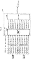
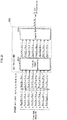
codeword length 16200 bits. In DVB-T2 a column-row interleaver is not used for QPSK (4QAM) constellations.[Table 1] Modulation Columns Nc Rows Nr 16QAM 8 (2 × 4) 2025 64QAM 12(2 × 6) 1350 256QAM 8(1 × 8) 2025 - The write start position of every column is twisted (i.e. cyclically shifted) by the twisting parameter tc according to Table 2. In Table 2, the twisting parameter tc of all columns of the interleaver matrix is listed for all relevant constellation sizes (referred to as "modulation" in Table 2) and LDPC codeword lengths Nldpc of an LDPC codeword.
[Table 2] Modulation Columns Nc LDPC codeword length Nldpc Twisting Parameter tc Column 0 1 2 3 4 5 6 7 8 9 10 11 12 13 14 15 16- QAM 8 64800 0 0 2 4 4 5 7 7 - - - - - - - - 16200 0 0 0 1 7 20 20 21 - - - - - - - - 64- QAM 12 64800 0 0 2 2 3 4 4 5 5 7 8 9 - - - - 16200 0 0 0 2 2 2 3 3 3 6 7 7 - - - - 256- QAM 16 64800 0 2 2 2 2 3 7 15 16 20 22 22 27 27 28 32 8 16200 0 0 0 1 7 20 20 21 - - - - - - - - -
Fig. 4 shows a process performed by the column-row interleaver 1125, assuming that a long frame with 64800 bits is generated by the FEC encoder 1110 (which includes theBCH encoder 1111 and LDPC encoder 1115) and that a 16QAM constellation is used as the QAM constellation. Correspondingly, the interleaver matrix has 8100 rows and 8 columns. - As shown in
Fig. 4 , the column-row interleaver 1125 serially writes the data bits, which are received from theparity interleaver 1121, column-wise into an interleaver matrix with twist. In the process of twisting, the write start position of each column is twisted by using the twisting parameter tc shown in Table 2. Subsequently, the column-row interleaver 1125 serially reads out the bits row-wise from the interleaver matrix. The MSB (most significant bit) of the baseband frame header is written and read out first. Note that the "LSB of FEC Frame" inFig. 4 refers to the LSB (least significant bit) of the FEC frame after column-row interleaving with twist (i.e., column twist interleaving). -
Figs. 5A, 5B ,6A, and 6C show an example of column-row interleaving for LDPC codewords ofcodeword length 16200 bits, for a number of columns equal to 8 and 12 respectively. - More specifically,
Figs 5A and6A are relevant to the writing of bits by the column-row interleaver 1125, whereasFigs. 5B and6B are relevant to the reading of bits by the column-row interleaver 1125. In each figure, each smallest square represents one bit of the LDPC codeword, and each black square represents the first bit of the LDPC codeword. In addition, the arrow indicates the order in which the bits are written into or read out of the interleaver matrix. Note that the process of twisting is not shown inFigs. 5A, 5B ,6A, and 6B . - Suppose that the interleaver matrix has 8 columns, the LDPC codeword bits are written in the order of (
row 1, column 1), (row 2, column 1), ... (row 2025, column 1), (row 1, column 2), ... (row 2025, column 8), as shown inFig. 5A , and read out in the order of (row 1, column 1), (row 1, column 2), ... (row 1, column 8), (row 2, column 1), ... (row 2025, column 8), as shown inFig. 5B . - Note that only two cases, which are (1) LDPC codewords of
codeword length 16200, for a number of columns equal to 8, and (2) LDPC codewords ofcodeword length 16200, for a number of columns equal to 12 are relevant for the present invention. - Prior to the QAM mapping, each LDPC codeword having been bit-interleaving by the bit interleaver 1120 is first demultiplexed into parallel cell words by the bit-to-
cell demultiplexer 1130. Each cell word demultiplexed contains as many bits as are encoded in one QAM constellation (ηMOD), that is, 2 bits for QPSK (4QAM) constellation, 4 bits for 16QAM constellation, 6 bits for 64QAM constellation, and 8 bits for 256QAM constellation. The resulting number of QAM data cells per LDPC codeword (FEC block) ofcodeword length 16200 bits is therefore 16200/ηMOD. That is, 8100 cells for QPSK, 4050 cells for 16QAM, 2700 cells for 64QAM, and 2025 cells for 256QAM. - The following now describes the bit-to-
cell demultiplexer 1130 shown inFig. 2 , with reference toFigs. 7 through 10 . -
Fig. 7 illustrates the input and output of the bit-to-cell demultiplexer 1130 shown inFig. 2 . - The bit stream from the bit interleaver 1120 is demultiplexed by the bit-to-
cell demultiplexer 1130 into sub-bitstreams as shown inFig. 7 . The number of the sub-bitstreams Nsubstreams is two for QPSK (4QAM) constellations and equal with the number of columns of the interleaver matrix in the column-row interleaver 1125 for higher-order constellations (16QAM, 64QAM, 256QAM). In the latter case the demultiplexing also contains a bit permutation step (which is conceptually equivalent to a permutation of the columns of the interleaver matrix in the column-row interleaver). -
Fig. 8 is a block diagram of the bit-to-cell demultiplexer for 16QAM constellation. Note thatFig. 8 specifically refers to the case for which the number of sub-bitstreams Nsubstreams = 8, where each sub-bitstream has 16200/8 = 2025 bits. - The bit-to-
cell demultiplexer 1130A shown inFig. 8 includes asimple demultiplexer 1131A and aDEMUX permutator 1135A. - The
simple demultiplexer 1131A receives one bit stream (v0, v1, v2, ...) from the bit interleaver 1120 and demultiplexes the received bit stream into 8 sub-bitstreams, namely the first sub-bitstream (v0,0, v0,1, v0,2, ...) to the eighth sub-bitstream (v7,0, v7,1, v7,2, ...). Thesimple demultiplexer 1131A then outputs the resulting 8 sub-bitstreams to theDEMUX permutator 1135A. Note that the output bits vi,j of thesimple demultiplexer 1131A correspond to the input bits vi+8×j to thesimple demultiplexer 1131A. - The
DEMUX permutator 1135A receives the 8 sub-bitstreams from thesimple demultiplexer 1131A, permutes the 8 sub-bitstreams received, andoutputs 8 sub-bitstreams obtained as a result of the permutation. As shown inFig. 8 , the output bits b0,i to b7,i (i = 0, 1, 2, ...) of theDEMUX permutator 1135A include two cell words (y0,2×i to y3,2×i and y0,2×i+1 to y3,2×i+1) and each cell word is forwarded to theQAM mapper 1140 for 16QAM. -
Fig. 9 is a block diagram of the bit-to-cell demultiplexer for 64QAM constellation. Note thatFig. 9 specifically refers to the case where the number of sub-bitstreams Nsubstreams = 12, where each sub-bitstream has 16200/12 = 1350 bits. - The bit-to-
cell demultiplexer 1130B shown inFig. 9 includes asimple demultiplexer 1131B and aDEMUX permutator 1135B. - The
simple demultiplexer 1131B receives one bit stream (vo, v1, v2, ...) from the bit interleaver 1120 and demultiplexes the received bit stream into 12 sub-bitstreams, namely the first sub-bitstream (v0,0, v0,1, v0,2, ...) to the twelfth sub-bitstream (v11,0, v11,1, v11,2, ...). Thesimple demultiplexer 1131B then outputs the resulting 12 sub-bitstreams to theDEMUX permutator 1135B. Note that the output bits vi,j of thesimple demultiplexer 1131B correspond to the input bits vi+12×j to thesimple demultiplexer 1131B. - The
DEMUX permutator 1135B receives the 12 sub-bitstreams from thesimple demultiplexer 1131B, permutes the 12 sub-bitstreams received, andoutputs 12 sub-bitstreams obtained as a result of the permutation. As shown inFig. 9 , the output bits b0,i to b11,i (i = 0, 1, 2, ...) of theDEMUX permutator 1135B include two cell words (y0,2×i to y5,2×i and y0,2×i+1 to y5,2×i+1) and each cell word is forwarded to theQAM mapper 1140 for 64QAM. -
Fig. 10 is a block diagram of the bit-to-cell demultiplexer for 256QAM constellation. Note thatFig. 10 specifically refers to the case where the number of sub-bitstreams Nsubstreams = 8, where each sub-bitstream has 16200/8 = 2025 bits. - The bit-to-
cell demultiplexer 1130C shown inFig. 10 includes asimple demultiplexer 1131C and aDEMUX permutator 1135C. - The
simple demultiplexer 1131C receives one bit stream (vo, v1, v2, ...) from the bit interleaver 1120 and demultiplexes the received bit stream into 8 sub-bitstreams, namely the first sub-bitstream (v0,0, v0,1, v0,2, ...) to the eighth sub-bitstream (v7,0, v7,1, v7,2, ...). Thesimple demultiplexer 1131C then outputs the resulting 8 sub-bitstreams to theDEMUX permutator 1135C. Note that the output bits vi,j of thesimple demultiplexer 1131C correspond to the input bits vi+8×j to thesimple demultiplexer 1131C. - The
DEMUX permutator 1135C receives the 8 sub-bitstreams from thesimple demultiplexer 1131C, permutes the 8 sub-bitstreams received, andoutputs 8 sub-bitstreams obtained as a result of the permutation. As shown inFig. 10 , the output bits b0,i to b7,i (i = 0, 1, 2, ...) of theDEMUX permutator 1135C includes one cell word (y0,i to y7,i) and the cell word is forwarded to theQAM mapper 1140 for 256QAM. - The bit-to-cell demultiplexing by the bit-to-
cell demultiplexer 1130 is defined as a mapping of the bit-interleaved input bits bdi onto the output bits be,do, where: - do is di div Nsubstreams;
- div is a function that returns an integer portion of the result obtained by dividing di by Nsubstreams;
- e is the demultiplexed sub-bitstream (sub-bitstream output from the bit-to-cell demultiplexer 1130) number (0 ≤ e < Nsubstreams);
- vdi is the input to the bit-to-
cell demultiplexer 1130; - di is the input bit number;
- be,do is the output from the bit-to-
cell demultiplexer 1130; and - do is the bit number of a given sub-bitstream output from the bit-to-
cell demultiplexer 1130. - Correspondingly, if the example configuration of
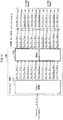
Fig. 4 is assumed, with the codeword length of 16200 bits and 16QAM constellation, 8 sub-bitstreams would be formed (Nsubstreams = 8) according to Table 1 above. Each sub-bitstream has 16200/8 = 2025 bits (do = di div Nsubstreams) and constitutes one column of the interleaver matrix. - The DVB-T2 standard defines bit-to-cell demultiplexing processes for all the available LDPC code rates in DVB-T2 (1/2, 3/5, 2/3, 3/4, 4/5, and 5/6), and constellation modes (QPSK, 16QAM, 64QAM and 256 QAM) (see Tables 13(a, b, c) in Clause 6.2.1 of Non-Patent Literature 1: EN 302.755 v1.2.1). These parameters shown in Tables 13(a, b, c) define permutations of the input bits to the output bits of a sub-bitstream.
- For instance, for LDPC codewords of
codeword length 16200 bits and the QAM constellation is a 16QAM constellation, an input bit vdi is permuted to an output bit be according to the following permutation rule (see Table 13(a) in Clause 6.2.1 of Non-Patent Literature 1: EN 302.755 v1.2.1). - That is, the permutation rule is v0 = b7, v1 = b1, v2 = b4, v3 = b2, v4 = b5, v5 = b3, v6 = b6, v7 = b0.
- This permutation rule is optimized for
code rates 1/2, 3/4, 4/5, and 5/6, such that the error rate at the output of the LDPC decoder in the receiver is minimized. - Except for QPSK (LDPC codeword length Nldpc = 64800 or 16200) and 256QAM (Nldpc=16200 only), the words of width Nsubstreams are split into two cell words of width ηMOD= Nsubstreams/2 at the output of the bit-to-cell demultiplexer. The first ηMOD =Nsubstreams/2 bits [bo,do ... bNsubstreams/2-1,do] form the first of a pair of output cell words [y0,2do ... yηmod-1, 2do] and the remaining output bits [bNsubstreams/2, do ... bNsubstreams-1,do] form the second output cell word [y0,2do+1 ... Yηmod-1,2do+1] fed to the QAM mapper.
- In the case of QPSK (LDPC LDPC codeword length Nldpc = 64800 or 16200) and 256QAM (Nldpc =16200 only), the words of width Nsubstreams from the bit-to-cell demultiplexer form the output cell words and are fed directly to the QAM mapper (so: [y0,do ... yηmod-1,do] = [b0,do ... bNsubstreams-1,do]).
- In particular, the number of cell words involved in a DEMUX permutation by the DEMUX permutator is either one (for 256QAM) or two (for 16QAM and 64QAM).
- Put differently, the DEMUX permutation is conceptually equivalent to a permutation of the columns in the interleaver matrix of the column-row interleaver of the bit-interleaver.
- Subsequently, each cell word output from the bit-to-cell demultiplexer is modulated according to a particular mapping constellation (such as QPSK, 16QAM, 64QAM or 256QAM). The constellations and the details of the Gray mapping applied to the bits according to DVB-T2 are illustrated in
Figs. 11, 12 ,13 and14 . - A next-generation digital broadcast standard for handheld reception is currently under development in the DVB standardization body under the name DVB-NGH. This DVB-NGH standard will use the same BICM structure as explained above, which comprises FEC encoding, bit-interleaving, demultiplexing, and QAM constellation mapping. In addition to some of the DVB-T2 LDPC code rates, two additional LDPC code rates (namely 7/15 and 8/15) are added. The same QAM constellations as DVB-T2 will remain, i.e. QPSK (4QAM) constellation, 16QAM constellation, 64QAM constellation, and 256QAM constellation.
- Only short 16K LDPC codewords, i.e. with 16200 bits, will be used in DVB-NGH. In DVB-NGH LDPC codes have been proposed to be used for the newly introduced code rates of 7/15 and 8/15. The particular LDPC codes probably to be used for the code rates of 7/15 and 8/15 are depicted respectively in
Figs. 25 and26 , and the contents ofNon-Patent Literature 2 are also helpful. - The description of the codes in
Figs. 25 and26 is identical to that used in the DVB-S2 standard, more exactly in Clause 5.3.2 and Annexes B and C of Non-Patent Literature 3 (ETSI EN 302 307, V1.2.1, published on April 2009).Fig. 25 shows the addresses of the parity bit accumulators for the LDPC code having a codeword length of 16200 bits with the code rate of 7/15.Fig. 26 shows the addresses of the parity bit accumulators for the LDPC code having a codeword length of 16200 bits with the code rate of 8/15. The parallel or cyclic factor has the same value 360 like in DVB-S2. - Since the disclosure of
Figs. 25 and26 comply with the contents ofNon-Patent Literature 3, it is naturally assumed that the LDPC codes are readily understandable to those skilled in the art based onFigs. 25 and26 . Yet, the following describes an example in which the contents of Non-Patent Literature 3 (Clause 5.3.2 and Annexes B and C of ETSI EN 302 307 V1.2.1 (2009, April)) are applied. - The LDPC encoder systematically encodes an information block (output of the BCH encoder) i of size Kldpc into an LDPC codeword c of size of Nldpc, as in
Equation 1 below.

- where i 0, i 1, ···, i Kldpc -1 : information bits
- p 0, p 1, ···, p Nldpc -Kldpc -i parity bits
- Note that the parameters (Nldpc and Kldpc) for LDPC code with
code rate 7/15 are (16200 and 7560). - The task of the LDPC encoder is to compute the Nldpc - Kldpc parity bits for every block of Kldpc information bits.
- First, the parity bits are initialized as shown in
Equation 2.

- The first information bit io is accumulated at each parity bit address specified in the first row of
Fig. 25 . More specifically, the operations ofEquation 3 are performed.

- For the next 359 information bits im (m = 1, 2, ... 359), im is accumulated at each parity bit address {x + (m mod 360) × q}mod (Nldpc - Kldpc). Note that x denotes the address of the parity bit accumulator corresponding to the first bit i0, and q is a constant dependent on the
code rate 7/15, which in this case is 24. The value of q is given by q = (Nldpc - Kldpc)/360. - For the 361st information bit i360, the addresses of the parity bit accumulators are given in the second row of
Fig. 25 . In a similar manner, for the next 360 information bits im (m = 361, 362, ... 719), the addresses of the parity bit accumulators are given by {x + (m mod 360) × q} mod (Nldpc - Kldpc). Note that x denotes the address of the parity bit accumulator for the 360th information bit i360, i.e. the entries in the second row ofFig. 25 . - In a similar manner, for every group of 360 new information bits, a new row from
Fig. 25 is used to find the addresses of the parity bit accumulators. - After all of the information bits are exhausted, the final parity bits are obtained as follows.
- Sequentially perform the operations of
Equation 4 starting with i = 1.

- Final content of pi (i = 0, 1, ... Nldpc - Kldpc - 1) is equal to the parity bit pi.
- Note that the same description as given above in the example directed to
Fig. 25 is applicable toFig. 26 , by simply replacing the values of the entries in each row ofFig. 25 with those ofFig. 26 . Yet, the parameters (Nldpc and Kldpc) for LDPC code are (16200 and 8640) and that q = 21. - Although the above description of LDPC codes complies with the notation of DVB-S2, according to the notation of DVB-T2 or DVB-NGH, q mentioned above is written as Qldpc, for example.
- In the DVB-NGH standard, currently no permutations by bit-to-cell demultiplexer are defined for the
code rates 7/15 and 8/15 for respective 16QAM constellation, 64QAM constellation, and 256QAM constellation. As in DVB-T2, QPSK (4QAM) constellation does not need such a permutation by the bit-to-cell demultiplexer. It is because the two bits encoded in a QPSK constellation have the same robustness level. - In order to maximize the performance of the new LDPC codes of
rate 7/15 and 8/15 in conjunction with various QAM constellation sizes and under various reception conditions, new optimized permutation rules are required for the bit-to-cell demultiplexing. - In the following, several embodiments of the invention will be explained in detail, with reference to the drawings. The explanations should not be understood as limiting the invention, but as a mere example of the general principles of the present invention. A skilled person should be aware that the general principles of the embodiments as laid out in the "
Supplement 2" section of this specification can be applied to different scenarios and in ways that are not explicitly described herein. - Most of the embodiments of the present invention explained in the following refer to the DVB-NGH system. The new DVB-NGH standard will update and replace the DVB-H standard for digital broadcasting to mobile devices.
- Though not yet finally decided, it is assumed that the DVB-NGH system adopts a structure similar to the one of DVB-T2 subsystem, as explained above in the "Findings by Present Inventor Leading to the Invention" section of this specification. This however should not restrict the scope of protection. Actually, the embodiments of the present invention can be applied to any system having the structural features as explained in the "
Supplement 2" section of this specification. - Various embodiments of the present invention provide a system for processing bit signals to be transmitted before they are input to a QAM mapper. Further embodiments of the present invention provides a system for processing bit signals received from the QAM demapper (for performing the inverse process of the process conducted on the transmission bits at the transmitting side).
- It is assumed that a digital signal, comprising e.g. an audio and/or video signal, is to be transmitted/broadcast from transmitters and is intended to be received by receivers, such as mobile terminals.
- The following describes a BICM encoder according to an embodiment of the present invention, with reference to the drawings. Note that the BICM encoder is provided in a transmitter.
-
Fig. 15 is a block diagram of the BICM encoder according to the embodiment of the present invention. The BICM encoder shown inFig. 15 basically corresponds to the BICM encoder according to DVB-T2 and described in detail in the "Findings by Present Inventor Leading to the Invention" section with reference toFigs. 1 through 14 . - The
BICM encoder 100 shown inFig. 15 includes anFEC encoder 110, abit interleaver 120, a bit-to-cell demultiplexer 130, and aQAM mapper 140. - The
FEC encoder 110 includes aBCH encoder 111 and anLDPC encoder 115. The contents described in the "Supplement 2" section is also applicable to a system in which theBCH encoder 111 upstream of theLDPC encoder 115 is omitted or replaced with an encoder for different code. - To the
BCH encoder 111, a digital signal (baseband signal), such as an audio and/or a video signal, consisting of information bits is input. TheBCH encoder 111 generates BCH parity bits by BCH encoding a baseband frame input thereto and outputs a BCH codeword to which the BCH parity bits are appended to theLDPC encoder 115. - The
LDPC encoder 115 encodes the BCH codeword with a specific LDPC code to generate LDPC parity bits. Note that the LDPC code used here in this embodiment is an LDPC code having a codeword length of 16200 bits withcode rate 7/15 according toFig. 25 or an LDPC code having a codeword length of 16200 bits withcode rate 8/15 according toFig. 26 . - The
LDPC encoder 115 outputs to the bit interleaver 120 an LDPC codeword of Nldpc = 16200 bits to which the LDPC parity bits obtained as a result of the LDPC encoding are appended (i.e., a bitstream of data packets consisting of Nldpc = 16200 bits). It should be noted that the output of a bitstream of data packets consisting of Nldpc = 64800 bits from theLDPC encoder 115 is not foreseen for transmission/reception of signals for handheld devices according to DVB-NGH standard. The encoded 16200-bit LDPC codewords are input to thebit interleaver 120 that performs parity interleaving and column twist interleaving as explained in the DVB-T2 standard, Clause 6.1.3. - The bit interleaver 120 includes a
parity interleaver 121 and a column-row interleaver 125. - The
parity interleaver 121 performs parity interleaving to permute the order of parity bits of the 16200-bit LDPC codeword and outputs the resulting LDPC codeword to the column-row interleaver 125. - More specifically, let λ denote the input to the parity interleaver 121 and u denote the output from the
parity interleaver 121, theparity interleaver 121 performs the operations ofEquation 5.

- In
Equation 5, Kldpc denotes the number of information bits of an LDPC codeword and information bits are not interleaved. The cyclic factor of the parity-check matrix is 360. Note that Qldpc = 24 forcode rate 7/15, whereas Qldpc = 21 forcode rate 8/15. - The column-
row interleaver 125 performs column twist interleaving (column-row interleaving with twist) on the parity interleaved 16200-bit LDPC codeword received from the parity interleaver 121 and outputs the 16200-bit LDPC codeword resulting from the column twist interleaving to the bit-to-cell demultiplexer 130. - The interleaver matrix used by the column-
row interleaver 125 for column twist interleaving is a matrix whose number of entries (a value obtained by multiplying the number of columns by the number of rows) is 16200, which is equal to the number of LDPC codeword bits. That is, the dimensions of the interleaver matrix differ (i.e., the number of columns as well as the number of rows differ) depending on the type of modulation being used in theQAM mapper 140. As previously explained, for 16QAM and Nldpc = 16200, the number of rows Nr = 2025 and the number of columns Nc = 8. For 64QAM and Nldpc = 16200, the number of rows Nr = 1350 and the number of columns Nc = 12. For 256QAM and Nldpc = 16200, the number of rows Nr = 2025 and the number of columns Nc = 8. - Considering column twist and the number of columns, 8 or 12, the column-
row interleaver 125 serially writes column-wise the 16200 data bits (parity interleaved LDPC codeword), which is output from theparity interleaver 121, with twist. In the process of twisting, the write start position of each column is twisted by using the column twisting parameters tc shown in Table 2. Subsequently, the column-row interleaver 125 serially reads out the 16200 bits from the interleaver matrix row-wise (seeFigs. 4 ,5 , and6 for reference). - It should be noted, however, that the embodiments of the present invention, in particular the various permutation rules used by the bit-to-cell demultiplexer, can be applied to column twisting parameters not listed in Table 2. Furthermore, though column twist interleaving is part of the DVB-T2 system, and thus will probably be part of the DVB-NGH system, the embodiments of the present invention can also be applied to a column-row interleaving process without column twist.
- After the column twist interleaving process by the column-
row interleaver 125, the bit-to-cell demultiplexer 130 permutes the 16200-bit LDPC codewords according to the various examples of the embodiment of the present invention. The permutation processing, and in particular the permutation rules which are to be applied, depend on: (1) the LDPC code used by theLDPC encoder 115, further characterized by its codeword length and the code rate; and on (2) the QAM constellation size used by theQAM mapper 140. - As explained before, the bit-to-
cell demultiplexer 130 demultiplexes the bits of the bit-interleaved LDPC codeword, which is input from thebit interleaver 120, into parallel cell words. Then, the bit-to-cell demultiplexer 130 performs the permutation after which the permuted cell words are mapped into constellation symbols according to the specified QAM mapping. The number of output QAM data cells (the number of cell words) and the effective number of bits per cell word ηMOD is the same as for DVB-T2 explained in the "Findings by Present Inventor Leading to the Invention" section of this specification. Particularly, there are 8100 cells for QPSK (4QAM), 4050 cells for 16QAM, 2700 cells for 64QAM, and 2025 cells for 256 QAM. - The following now describes the bit-to-
cell demultiplexer 130 shown inFig. 15 , with reference toFigs. 16 through 19 . -
Fig. 16 illustrates the input and output of the bit-to-cell demultiplexer 130 shown inFig. 15 . - The bitstream from the
bit interleaver 120 is demultiplexed by the bit-to-cell demultiplexer 130 into sub-bitstreams as shown inFig. 16 . The number of sub-bitstreams Nsubstreams is the same as for DVB-T2. In particular, the number of sub-bitstreams Nsubstreams is 2 for QPSK (4QAM) constellations, 8 for 16QAM constellation, 12 for 64QAM constellation, and 8 for 256QAM constellation. - After the bit-to-cell demultiplexing, a permutation is carried out by a particular interleaving of input bits bdi onto the output bits be,do. Note that do = di div Nsubstreams, and div is a function that returns an integer portion of the result obtained by dividing di by Nsubstreams. Further, e is the demultiplexed bitstream number (0 ≤ e < Nsubstreams) (i.e., the number identifying the sub-bitstream output from the bit-to-cell demultiplexer 130). Still further, vdi is the input bits to the bit-to-
cell demultiplexer 130, and di is the input bit number. Still further, be,do is the output bits from the bit-to-cell demultiplexer 130, and do is the bit number of a given sub-bitstream output from the bit-to-cell demultiplexer 130. -
Fig. 17 is a block diagram of the bit-to-cell demultiplexer for 16QAM constellation. Note thatFig. 17 specifically refers to the case where the number of sub-bitstreams Nsubstreams = 8, where each sub-bitstream has 16200/8 = 2025 bits. - The bit-to-
cell demultiplexer 130A shown inFig. 17 includes asimple demultiplexer 131A and aDEMUX permutator 135A. - The
simple demultiplexer 131A receives one bit stream (vo, v1, v2, ...) from the bit interleaver 120 and demultiplexes the received bit stream into 8 sub-bitstreams, namely the first sub-bitstream (v0,0, v0,1, v0,2, ...) to the eighth sub-bitstream (v7,0, v7,1, v7,2, ...). Thesimple demultiplexer 131A then outputs the resulting 8 sub-bitstreams to theDEMUX permutator 135A. Note that the output bits vi,j of thesimple demultiplexer 131A correspond to the input bits vi+8×j to thesimple demultiplexer 131A. - The
DEMUX permutator 135A receives the 8 sub-bitstreams from thesimple demultiplexer 131A, permutes the 8 sub-bitstreams received, andoutputs 8 sub-bitstreams obtained as a result of the permutation. As shown inFig. 17 , the output bits b0,i to b7,i (i = 0, 1, 2, ...) of the DEMUX permutator 135A include two cell words (y0,2×i to y3,2×i and y0,2×i+1 to y3,2×i+1), and each cell word is forwarded to theQAM mapper 140 for 16QAM. -
Fig. 18 is a block diagram of the bit-to-cell demultiplexer for 64QAM constellation. Note thatFig. 18 specifically refers to the case for which the number of sub-bitstreams Nsubstreams = 12, where each sub-bitstream has 16200/12 = 1350 bits. - The bit-to-
cell demultiplexer 130B shown inFig. 18 includes asimple demultiplexer 131B and aDEMUX permutator 135B. - The
simple demultiplexer 131B receives one bit stream (vo, v1, v2, ...) from the bit interleaver 120 and demultiplexes the received bit stream into 12 sub-bitstreams, namely the first sub-bitstream (v0,0, v0,1, v0,2, ...) to the twelfth sub-bitstream (v11,0, v11,1, v11,2, ...). Thesimple demultiplexer 131B then outputs the resulting 12 sub-bitstreams to theDEMUX permutator 135B. Note that the output bits vi,j of thesimple demultiplexer 131B correspond to the input bits vi+12×j to thesimple demultiplexer 131B. - The
DEMUX permutator 135B receives the 12 sub-bitstreams from thesimple demultiplexer 131B, permutes the 12 sub-bitstreams received, andoutputs 12 sub-bitstreams obtained as a result of the permutation. As shown inFig. 18 , the output bits b0,i to b11,i (i = 0, 1, 2, ...) of theDEMUX permutator 135B include two cell words (y0,2×i to y5,2×i and y0,2×i+1 to y5,2×i+1) and each cell word is forwarded to theQAM mapper 140 for 64QAM. -
Fig. 19 is a block diagram of the bit-to-cell demultiplexer for 256QAM constellation. Note thatFig. 19 specifically refers to the case for which the number of sub-bitstreams Nsubstreams = 8, where each sub-bitstream has 16200/8 = 2025 bits. - The bit-to-
cell demultiplexer 130C shown inFig. 19 includes asimple demultiplexer 131C and aDEMUX permutator 135C. - The
simple demultiplexer 131C receives one bit stream (vo, v1, v2, ...) from the bit interleaver 120 and demultiplexes the received bit stream into 8 sub-bitstreams, namely the first sub-bitstream (v0,0, v0,1, v0,2, ...) to the eighth sub-bitstream (v7,0, v7,1, v7,2, ...). Thesimple demultiplexer 1131C then outputs the resulting 8 sub-bitstreams to theDEMUX permutator 135C. Note that the output bits vi,j of thesimple demultiplexer 131C correspond to the input bits vi+8×j to thesimple demultiplexer 131C. - The
DEMUX permutator 135C receives the 8 sub-bitstreams from thesimple demultiplexer 131C, permutes the 8 sub-bitstreams received, andoutputs 8 sub-bitstreams obtained as a result of the permutation. As shown inFig. 19 , the output bits b0,i to b7,i (i = 0, 1, 2, ...) of theDEMUX permutator 135C includes one cell word (y0,i to y7,i) and the cell word is forwarded to theQAM mapper 1140 for 256QAM. - The cell words obtained as a result of the processing by the bit-to-cell demultiplexer 130 (130A through 130C) are serially output to the
QAM mapper 140 shown inFig. 15 . TheQAM mapper 140 maps the cell words (the output of the bit-to-cell demultiplexer) to the constellation symbols according to the particular one of 16QAM, 64QAM and 256QAM modulation ofFig. 12 ,13 and14 , i.e. according to the bit labeling used in the DVB-T2 standard. - In the following, demultiplexing parameters will be presented according to various embodiments of the invention for applying permutation schemes for different LDPC codes and different modulation modes. The following permutation is applied in the DEMUX permutator of the bit-to-cell demultiplexer, according to
Figs. 17 through 19 , as being part ofFig. 15 . - The following describes the permutation rules used by the DEMUX permutator provided in the bit-to-cell demultiplexer, for the following three cases:
- Case A: The LDPC encoder uses an LDPC code having a codeword length of 16200 bits and
code rate 7/15 as shown inFig. 25 , and the QAM mapper uses a 64QAM constellation; - Case B: The LDPC encoder uses an LDPC code having a codeword length of 16200 bits and
code rate 7/15 as shown inFig. 25 , and the QAM mapper uses a 256QAM constellation; and - Case C: The LDPC encoder uses an LDPC code having a codeword length of 16200 bits and
code rate 8/15 as shown inFig. 26 , and the QAM mapper uses a 64QAM constellation. - The following describes the processing performed by the bit-to-
cell demultiplexer 130B shown inFig. 18 , according to one example of the embodiment of the present invention. This example is directed to the case where theLDPC encoder 115 uses the LDPC code having a codeword length of 16200 andcode rate 7/15 as shown inFig. 25 , and theQAM mapper 140 uses a 64QAM modulation as the modulation scheme. - The permutation in the
DEMUX permutator 135B is performed as depicted inFig. 18 on the 12 bits of a row of the interleaver matrix that is read out row-wise and then demultiplexed according toFig. 18 . - After the demultiplexing process, the
DEMUX permutator 135B permutes the 12 input bits vdi (vdi,do) to the 12 output bits be (be,do) according to the following permutation rule. - The permutation rule is v0 = b2, v1 = b4, v2 = b0, v3 = b1, v4 = b3, v5 = b6, v6 = b5, v7 = b8, v8 = b10, v9 = b7, v10 = b11, v11 = b9.
- After performing the above permutation, two cell words are extracted for each be. The two bit-to-cell words y0-y5 are output to the
QAM mapper 140 of the 64QAM type for being mapped to two consecutive modulation symbols. - The following describes the processing performed by the bit-to-
cell demultiplexer 130C shown inFig. 19 , according to another example of the embodiment of the present invention. This example is directed to the case where theLDPC encoder 115 uses the LDPC code having a codeword length of 16200 andcode rate 7/15 as shown inFig. 25 , and theQAM mapper 140 uses a 256QAM modulation as the modulation scheme. - The permutation in the
DEMUX permutator 135C is performed as depicted inFig. 19 on the 8 bits of a row of the interleaver matrix that is read out row-wise and then demultiplexed according toFig. 19 . - After the demultiplexing process, the
DEMUX permutator 135C permutes the 8 input bits vdi (vdi,do) to the 8 output bits be (be,do) according to the following permutation rule. - That is, the permutation rule is v0 = b2, v1 = b6, v2 = b0, v3 = b1, v4 = b4, v5 = b6, v6 = b3, v7 = b7.
- After performing the above permutation, one cell word is extracted for each be. The bit-to-cell word y0-y7 is output to the
QAM mapper 140 of the 256QAM type for being mapped to two consecutive modulation symbols. - The following describes the processing performed by the bit-to-
cell demultiplexer 130B shown inFig. 18 , according to yet another example of the embodiment of the present invention. This example is directed to the case where theLDPC encoder 115 uses the LDPC code having a codeword length of 16200 andcode 8/15 as shown inFig. 26 , and theQAM mapper 140 uses a 64QAM modulation as the modulation scheme. - The permutation in the
DEMUX permutator 135B is performed as depicted inFig. 18 on the 12 bits of a row of the interleaver matrix that is read out row-wise and then demultiplexed according toFig. 18 . - After the demultiplexing process, the
DEMUX permutator 135B permutes the 12 input bits vdi (vdi,do) to the 12 output bits be (be,do) according to the following permutation rule. - The permutation rule is v0 = b0, v1 = b4, v2 = b5, v3 = b1, v4 = b6, v5 = b7, v6 = b2, v7 = b10, v8 = b3, v9 = b8, v10 = b9, v11 = b11.
- After performing the above permutation, two cell words are extracted for each be. The two bit-to-cell words y0-y5 are output to the
QAM mapper 140 of the 64QAM type for being mapped to two consecutive modulation symbols. - The following describes a BICM decoder according to an embodiment of the present invention, with reference to the drawings. Note that the BICM decoder is provided in a receiver. Examples of apparatuses having the BICM decoder according to this embodiment include handheld devices, mobile phones, tablet PCs, notebooks, televisions, etc.
- The processing by the BICM decoder provided in the receiver will basically be the reverse of the above-explained processing performed by the BICM encoder provided in the transmitter. In summary, complex cells will be demodulated according to the constellation mapping (QPSK, 16QAM, 64QAM, 256QAM) to determine the transmitted bit-to-cell words. One cell word (in the case of 256QAM) or two cell words (in the cases of 16QAM and 64QAM) will be bit-permuted according to a permutation rule being inverse to that in the transmitting side, and then multiplexed into a bit stream. The resulting bit stream is subjected to column-row deinterleaving by a column-row deinterleaver, as well as to parity deinterleaving by a parity deinterleaver. Note that bits deinterleaved by the parity deinterleaver are parity bits only. The output bits of the parity deinterleaver are decoded by the LDPC decoder, which is in concordance with the transmitting side LDPC coding. Then, a stream of bits resulting from the decoding is output.
- The following describes the BICM decoder in detail.
-
Fig. 20 is a block diagram of the BICM decoder according to the embodiment of the present invention. - The
BICM decoder 300 shown inFig. 20 includes aQAM demapper 310, a cell-to-bit multiplexer 320, abit deinterleaver 330, and anFEC decoder 340. - The
QAM demapper 310 demodulates complex cells according to a particular modulation mode (such as 16QAM, 64QAM or 256QAM) and outputs the resulting cell words to the cell-to-bit multiplexer 320. The cell words corresponding to 16QAM, 64QAM, and 256QAM comprise 4, 6 and 8 bits, respectively. - The QAM demodulation performed by the QAM demapper 310 is in accordance with the QAM modulation performed by the
QAM mapper 140 provided in the transmitter. If theQAM mapper 140 of the transmitter performs 16QAM modulation according to the DVB-T2 labeling ofFig. 12 , the QAM demapper 310 performs demodulation based on the same 16QAM ofFig. 12 , to demodulate each modulation symbol (complex cell) into a cell word of 4 bits. The same applies to the all the QAM modulations according toFigs. 11 ,13 , and14 . - The cell-to-
bit multiplexer 320 includes a permutation block and a multiplexing block. In the receiving side, the permutation block processes the demodulated bits according to a permutation rule depending on the modulation mode and the LDPC code used in the transmitting side (and conversely in the receiving side). - The following now describes the cell-to-
bit multiplexer 330 shown inFig. 20 , with reference toFigs. 21 through 24 . -
Fig. 21 illustrates the input and output of the cell-to-bit multiplexer 320 shown inFig. 20 . - The cell words y consisting of input bits b are input to the cell-to-
bit multiplexer 320 and are permuted by the cell-to-bit multiplexer 320 to generate output words v. -
Fig. 22 is a block diagram of the cell-to-bit multiplexer for 16QAM constellation. - The cell-to-
bit multiplexer 320A shown inFig. 22 includes aninverse DEMUX permutator 321A and asimple multiplexer 325A. - The
inverse DEMUX permutator 321A receives 8 sub-bitstreams (8 bits b0-b7 which form two cell words of 4 bits y0-y3), which are input from the QAM demapper 140 for 16QAM. Theinverse DEMUX permutator 321A performs a permutation on the received 8 sub-bitstreams (i.e., a permutation to restore the order of sub-bitstreams that is before the permutation by the DEMUX permutator 135A in the transmitting side) and outputs the resulting 8 sub-bitstreams to thesimple multiplexer 325A. - The
simple multiplexer 325A multiplexes the 8 sub-bitstreams obtained as a result of the permutation to a single bit-stream of 16200 bits to output. The resulting output bits vi+8×j of thesimple multiplexer 325A correspond to the input bits vi,j of thesimple multiplexer 325A. -
Fig. 23 is a block diagram of the cell-to-bit multiplexer for 64QAM constellation. - The cell-to-
bit multiplexer 320B shown inFig. 23 includes aninverse DEMUX permutator 321B and asimple multiplexer 325B. - The
inverse DEMUX permutator 321B receives 12 sub-bitstreams (12 bits b0-b11 which form two cell words of 6 bits y0-y5), which are input from the QAM demapper 140 for 64QAM. Theinverse DEMUX permutator 321B performs a permutation on the received 12 sub-bitstreams (i.e., a permutation to restore the order of sub-bit streams that is before the permutation by theDEMUX permutator 135B in the transmitting side) and outputs the resulting 12 sub-bitstreams to thesimple multiplexer 325B. - The
simple multiplexer 325B multiplexes the 12 sub-bitstreams obtained as a result of the permutation to a single bit-stream of 16200 bits to output. The resulting output bits vi+12×j of thesimple multiplexer 325B correspond to the input bits vi,j of thesimple multiplexer 325B. -
Fig. 24 is a block diagram of the cell-to-bit multiplexer for 256QAM constellation. - The cell-to-
bit multiplexer 320C shown inFig. 24 includes an inverse DEMUX permutator 321C and asimple multiplexer 325C. - The inverse DEMUX permutator 321C receives 8 sub-bitstreams (8 bits b0-b7 which form one cell word of 8 bits y0-y7), which are input from the QAM demapper 140 for 256QAM. The inverse DEMUX permutator 321C performs a permutation on the received 8 sub-bitstreams (i.e., a permutation to restore the order of the substreams that is before the permutation by the
DEMUX permutator 135C in the transmitting side) and outputs the resulting 8 sub-bitstreams to thesimple multiplexer 325C. - The
simple multiplexer 325C multiplexes the 8 sub-bitstreams obtained as a result of the permutation to a single bit-stream of 16200 bits to output. The resulting output bits vi+8×j of thesimple multiplexer 325C correspond to the input bits vi,j of thesimple multiplexer 325C. - The details of the permutation rules used by the inverse DEMUX permutator will be described later.
- The bit deinterleaver 330 includes a column-
row deinterleaver 331 and aparity deinterleaver 335. - The column-
row deinterleaver 331 receives a bit stream composed of 16200 bits v (vo, v1, v2 ...) from the cell-to-bit multiplexer 320 (320A through 320C). The column-row deinterleaver 331 performs column-row deinterleaving with twist (column twist deinterleaving) on the 16200 input bits received. More specifically, the column-row deinterleaver 331 serially writes the 16200 input bits row-wise into a deinterleaver matrix, and then serially reads out the 16200 bits column-wise from the deinterleaver matrix with twist. In the process of twisting, the read start position of each column is twisted by using the twisting parameter tc shown in Table 2. The dimensions of the deinterleaver matrix depend on the constellation size used in the demodulation process by the QAM demapper 310 and the codeword length of the LDPC code used in the LDPC demodulation by theLDPC decoder 341. In more detail, in the case of the LDPC code having a codeword length of 16200 bits, the number of columns of the deinterleaver matrix is 8 for 16QAM, resulting in 2025 rows. For 64QAM the number of columns is 12, resulting in 1350 rows. For 256QAM the number of columns is 8, resulting in 2025 rows. - Note that the values of the twisting parameter tc used by the column-
row deinterleaver 331 are the same as the values of twisting parameter tc used by the column-row interleaver 125. Note that the column-row interleaver 125 may perform column-row interleaving without twist. In such a case, the column-row deinterleaver 331 performs column-row deinterleaving without twist. - The
parity deinterleaver 335 performs parity deinterleaving to permute the order of the LDPC parity bits out of the bits input from the column-row deinterleaver 331 (i.e., a to restore the order of the bits before the permutation by theparity interleaver 121 in the transmitting side) (see Equation 5). - The
FEC decoder 340 includes theLDPC decoder 341 and aBCH decoder 345. Note that the contents described in the "Supplement 2" section is also applicable to a system in which theBCH decoder 345 downstream of theLDPC decoder 341 is omitted or replaced with a decoder for different code. - The
LDPC decoder 341 performs the demodulation using the LDPC code used by theLDPC encoder 115 of the transmitter shown inFig. 15 . More specifically, an LDPC code having a codeword length of 16200 bits withcode rate 7/15 according toFig. 25 or an LDPC code having a codeword length of 16200 bits withcode rate 8/15 according toFig. 26 is used in the demodulation. - The
BCH decoder 345 performs a BCH decoding process on the data resulting from the demodulation by theLDPC decoder 341. - The following describes in detail the permutation rules used by the MUX permutator provided in the cell-to-bit multiplexer, for the following three cases.
- Case A: The LDPC decoder uses an LDPC code having a codeword length of 16200 bits and
code rate 7/15 as shown inFig. 25 , and the QAM demapper performs a 64QAM demodulation. - Case B: The LDPC decoder uses an LDPC code having a codeword length of 16200 bits and
code rate 7/15 as shown inFig. 25 , and the QAM demapper performs a 256QAM demodulation. - Case C: The LDPC decoder uses an LDPC code having a codeword length of 16200 bits and
code rate 8/15 as shown inFig. 26 , and the QAM demapper uses a 64QAM demodulation. - The following describes the processing performed by the cell-to-
bit multiplexer 320B shown inFig. 23 , according to one example of the embodiment of the present invention. Note that this example is directed to the case where theLDPC decoder 341 uses the uses the LDPC code having a codeword length of 16200 andcode rate 7/15 as shown inFig. 25 , and the QAM demapper 310 performs 64QAM demodulation. - The permutation by the
inverse DEMUX permutator 321B is performed as illustrated inFig. 23 on 12 bits that are serially input from theQAM demapper 310. - In the permutation process, the
inverse DEMUX permutator 321B permutes two cell words composed of 12 input bits be (be,do) to the 12 output bits vdi (vdi,do) according to the following permutation rule. - The permutation rule is v0 = b2, v1 = b4, v2 = b0, v3 = b1, v4 = b3, v5 = b6, v6 = b5, v7 = b8, v8 = b10, v9 = b7, v10 = b11, v11 = b9.
- The thus permuted bits v are multiplexed by the
simple multiplexer 325B. - The following describes the processing performed by the cell-to-
bit multiplexer 320C shown inFig. 24 , according to another example of the embodiment of the present invention. Note that this embodiment is directed to the case where theLDPC decoder 341 uses the uses the LDPC code having a codeword length of 16200 andcode rate 7/15 as shown inFig. 25 , and the QAM demapper 310 performs 256QAM demodulation. - The permutation by the
inverse DEMUX permutator 321B is performed as illustrated inFig. 24 on 8 bits that are serially input from theQAM demapper 310. - In the permutation process, the inverse DEMUX permutator 321C permutes one cell word composed of 8 input bits be (be,do) to the 8 output bits vdi (vdi,do) according to the following permutation rule.
- That is, the permutation rule is v0 = b2, v1 = b6, v2 = b0, v3 = b1, v4 = b4, v5 = b5, v6 = b3, v7 = b7.
- The thus permuted bits v are multiplexed by the
simple multiplexer 325C. - The following describes the processing performed by the cell-to-
bit multiplexer 320B shown inFig. 23 , according to yet another example of the embodiment of the present invention. Note that this example is directed to the case where theLDPC decoder 341 uses the uses the LDPC code having a codeword length of 16200 andcode rate 8/15 as shown inFig. 26 , and the QAM demapper 310 performs 64QAM demodulation. - The permutation by the
inverse DEMUX permutator 321B is performed as illustrated inFig. 23 on 12 bits that are serially input from theQAM demapper 310. - In the permutation process, the
inverse DEMUX permutator 321B permutes two cell words composed of 12 input bits be (be,do) to the 12 output bits vdi (vdi,do) according to the following permutation rule. - The permutation rule is v0 = b0, v1 = b4, v2 = b5, v3 = b1, v4 = b6, v5 = b7, v6 = b2, v7 = b10, v8 = b3, v9 = b8, v10 = b9, v11 = b11.
- The thus permuted bits v are multiplexed by the
simple multiplexer 325B. - The permutation rules used by the DEMUX permutators 135B and 135C shown in
Figs. 18 and19 as well as by theinverse DEMUX permutators Figs. 23 and24 are listed in Table 3 below.
- The present invention is not limited to the specific embodiments described above. Provided that the aims of the present invention and accompanying aims are achieved, other variations are also possible, such as the following.
- (1) The various embodiments described above may relate to the implementation using hardware and software. It is recognized that the various embodiments described above may be implemented or performed using computing devices (processors). A computing device or processor may for example be main processors/general purpose processors, digital signal processors (DSP), application specific integrated circuits (ASIC), field programmable gate arrays (FPGA) or other programmable logic devices, etc. The various embodiments of the invention may also be performed or embodied by a combination of these devices.
- (2) Further, the various embodiments described above may also be implemented by means of software modules, which are executed by a processor or directly in hardware. Also a combination of software modules and a hardware implementation may be possible. The software modules may be stored on any kind of computer readable storage media, for example RAM, EPROM, EEPROM, flash memory, registers, hard disks, CD-ROM, DVD, etc.
- The present invention is applicable to a bit-to-cell demultiplexer in a bit-interleaved coding and modulation system used for low-density parity codes, and also to a bit-to-cell demultiplexer corresponding to such a cell-to-bit multiplexer.
-
- 100
- BICM encoder
- 110
- FEC encoder
- 111
- BCH encoder
- 115
- LDPC encoder
- 120
- bit interleaver
- 121
- parity interleaver
- 125
- column-row interleaver
- 130
- bit-to-cell demultiplexer
- 130A-130C
- bit-to-cell demultiplexer
- 131
- simple demultiplexer
- 131A-131C
- simple demultiplexer
- 135
- DEMUX permutator
- 135A-135C
- DEMUX permutator
- 140
- QAM mapper
- 300
- BICM decoder
- 310
- QAM demapper
- 320
- cell-to-bit multiplexer
- 320A-320C
- cell-to-bit multiplexer
- 321
- inverse DEMUX permutator
- 321A-321C
- inverse DEMUX permutator
- 325
- simple multiplexer
- 325A-325C
- simple multiplexer
- 330
- bit deinterleaver
- 331
- column-row deinterleaver
- 335
- parity deinterleaver
- 340
- BICM decoder
- 341
- LDPC decoder
- 345
- BCH decoder
Claims (4)
- A transmission processing method comprising:an encoding step of encoding information bits into a codeword according to a low density parity check code with code rate 7/15 and a codeword length of 16200, the low density parity check code shown in Table 1-1:
 a parity-interleaving step of conducting parity interleaving on bits of the codeword obtained in the encoding step;a column-row-interleaving step of conducting column-row interleaving on bits of the parity interleaved codeword obtained in the parity-interleaving step, the column-row interleaving being conducted with or without twist;a bit-to-cell demultiplexing step of demultiplexing a sequence of bits column-row interleaved in the column-row interleaving step into 8 sequences of bits vi,j, wherein i denotes one of the eight sequences and bit vi,j corresponds to bit vi+8×j of said sequence of column-row interleaved bits and performing a permutation on the 8 sequences of bits according to a predetermined permutation rule so as to permute each set of 8 bits (v0,q, v1,q, v2,q, v3,q, v4,q, v5,q, v6,q, v7,q) to a set of 8 bits (b0,q, b1,q, b2,q, b3,q, b4,q, b5,q, b6,q, b7,q) to obtain 8 sequences of permuted bits, where q is an index;a mapping step of mapping each of 8-bit cell words (y0,q, y1,q, y2,q, y3,q, y4,q, y5,q, y6,q, y7,q) each composed of a set of 8 bits (b0,q, b1,q, b2,q, b3,q, b4,q, b5,q, b6,q, b7,q) of the 8 sequences of permuted bits obtained in the bit-to-cell demultiplexing step, into a complex cell (Re(Zq), Im(Zq)) according to the 256QAM, Quadrature Amplitude Modulation, constellation shown in Tables 1-2 and 1-3:
[Table 1-2] y0,q 1 1 1 1 1 1 1 1 0 0 0 0 0 0 0 0 y2,q 0 0 0 0 1 1 1 1 1 1 1 1 0 0 0 0 y4,q 0 0 1 1 1 1 0 0 0 0 1 1 1 1 0 0 y6,q 0 1 1 0 0 1 1 0 0 1 1 0 0 1 1 0 Re(zq ) -15 -13 -11 -9 -7 -5 -3 -1 1 3 5 7 9 11 13 15 [Table 1-3] whereiny1,q 1 1 1 1 1 1 1 1 0 0 0 0 0 0 0 0 y3,q 0 0 0 0 1 1 1 1 1 1 1 1 0 0 0 0 y5,q 0 0 1 1 1 1 0 0 0 0 1 1 1 1 0 0 y7,q 0 1 1 0 0 1 1 0 0 1 1 0 0 1 1 0 Im(zq ) -15 -13 -11 -9 -7 -5 -3 -1 1 3 5 7 9 11 13 15
(b0,q, b1,q, b2,q, b3,q, b4,q, b5,q, b6,q, b7,q) = (y0,q, y1,q, y2,q, y3,q, y4,q, y5,q, y6,q, y7,q),the predetermined permutation rule is:
v0,q = b2,q, v1,q = b6,q, v2,q = b0,q, v3,q = b1,q, v4,q = b4,q, v5,q = b5,q, v6,q = b3,q, v7,q = b7,q, andthe column-row interleaving of the column-row-interleaving step is performed using an interleaver matrix having a size of 2025 rows and 8 columns. - A transmitter (100) comprising:an encoder (110) adapted to encode information bits into a codeword according to a low density parity check code with code rate 7/15 and a codeword length of 16200, the low density parity check code shown in Table 2-1:
 a parity-interleaver (121) adapted to conduct parity interleaving on bits of the codeword obtained by the encoder;a column-row-interleaver (125) adapted to conduct column-row interleaving on bits of the parity interleaved codeword obtained by the parity-interleaver, the column-row interleaving being conducted with or without twist;a bit-to-cell demultiplexer (130) adapted to demultiplex a sequence of bits column-row interleaved by the column-row-interleaver into 8 sequences of bits vi,j, wherein i denotes one of the eight sequences and bit vi,j corresponds to bit vi+8×j of said sequence of column-row interleaved bits and perform a permutation on the 8 sequences of bits according to a predetermined permutation rule so as to permute each set of 8 bits (v0,q, v1,q,v2,q, v3,q, v4,q, v5,q, v6,q, v7,q) to a set of 8 bits (b0,q, b1,q, b2,q, b3,q, b4,q, b5,q, b6,q, b7,q) to obtain 8 sequences of permuted bits, where q is an index;a mapper (140) adapted to map each of 8-bit cell words (y0,q, y1,q, y2,q, y3,q, y4,q, y5,q, y6,q, y7,q) each composed of a set of 8 bits (b0,q, b1,q, b2,q, b3,q, b4,q, b5,q, b6,q, b7,q) of the 8 sequences of permuted bits obtained by the bit-to-cell demultiplexer, into a complex cell (Re(Zq), Im(Zq)) according to the 256QAM, Quadrature Amplitude Modulation, constellation shown in Tables 2-2 and 2-3:
[Table 2-2] y0.q 1 1 1 1 1 1 1 1 0 0 0 0 0 0 0 0 y2,q 0 0 0 0 1 1 1 1 1 1 1 1 0 0 0 0 y4,q 0 0 1 1 1 1 0 0 0 0 1 1 1 1 0 0 y6,q 0 1 1 0 0 1 1 0 0 1 1 0 0 1 1 0 Re(zq ) -15 -13 -11 -9 -7 -5 -3 -1 1 3 5 7 9 11 13 15 [Table 2-3] whereiny1,q 1 1 1 1 1 1 1 1 0 0 0 0 0 0 0 0 y3,q 0 0 0 0 1 1 1 1 1 1 1 1 0 0 0 0 y5,q 0 0 1 1 1 1 0 0 0 0 1 1 1 1 0 0 y7,q 0 1 1 0 0 1 1 0 0 1 1 0 0 1 1 0 Im(zq ) -15 -13 -11 -9 -7 -5 -3 -1 1 3 5 7 9 11 13 15
(b0,q, b1,q, b2,q, b3,q, b4,q, b5,q, b6,q, b7,q) = (y0,q, y1,q, y2,q, y3,q, y4,q, y5,q, y6,q, y7,q),the predetermined permutation rule is:
v0,q = b2,q, v1,q = b6,q, v2,q = b0,q, v3,q = b1,q, v4,q = b4,q, v5,q = b5,q, v6,q = b3,q, v7,q = b7,q andthe column-row interleaving by the column-row-interleaver is performed using an interleaver matrix having a size of 2025 rows and 8 columns. - A reception processing method comprising:a demapping step of demapping complex cells (Re(Zq), Im(Zq)) according to the 256QAM, Quadrature Amplitude Modulation, constellation shown in Tables 3-1 and 3-2:
[Table 3-1] y0,q 1 1 1 1 1 1 1 1 0 0 0 0 0 0 0 0 y2,q 0 0 0 0 1 1 1 1 1 1 1 1 0 0 0 0 y4,q 0 0 1 1 1 1 0 0 0 0 1 1 1 1 0 0 y6,q 0 1 1 0 0 1 1 0 0 1 1 0 0 1 1 0 Re(zq ) -15 -13 -11 -9 -7 -5 -3 -1 1 3 5 7 9 11 13 15 [Table 3-2] y1,q 1 1 1 1 1 1 1 1 0 0 0 0 0 0 0 0 y3,q 0 0 0 0 1 1 1 1 1 1 1 1 0 0 0 0 y5,q 0 0 1 1 1 1 0 0 0 0 1 1 1 1 0 0 y7,q 0 1 1 0 0 1 1 0 0 1 1 0 0 1 1 0 Im(zq ) -15 -13 -11 -9 -7 -5 -3 -1 1 3 5 7 9 11 13 15 a cell-to-bit multiplexing step of performing a permutation on 8 sequences of bits obtained as 8-bit cell words (y0,q, y1,q, y2,q, Y3,q, y4,q, y5,q, y6,q, y7,q)in the demapping step, according to a predetermined permutation rule so as to permute each set of 8 bits (b0,q, b1,q, b2,q, b3,q, b4,q, b5,q, b6,q, b7,q) of the 8 sequences of bits to a set of 8 bits (v0,q, v1,q,v2,q, v3,q, v4,q, v5,q, v6,q, v7,q) to obtain 8 sequences of permuted bits vi,j, wherein i denotes one of the 8 sequences and q and j are indices, and multiplexing the 8 sequences of permuted bits obtained as a result of the permutation into one sequence of bits such that bit vi+8×j of said one sequence corresponds to bit vi,j;a column-row-deinterleaving step of conducting column-row deinterleaving on the one sequence of bits obtained as a result of the multiplexing, the column-row deinterleaving being conducted with or without twist;a parity-deinterleaving step of conducting parity deinterleaving on the one sequence of bits obtained as a result of the column-row deinterleaving;a decoding step of decoding bits parity deinterleaved in the parity-deinterleaving step, according to a low density parity check code with code rate 7/15 and a codeword length of 16200, the low density parity check code shown in Table 3-3:wherein
(b0,q, b1,q, b2,q, b3,q, b4,q, b5,q, b6,q, b7,q) = (y0,q, y1,q, y2,q, y3,q, y4,q, y5,q, y6,q, y7,q),the predetermined permutation rule is:
v0,q = b2,q, v1,q = b6,q, v2,q = b0,q, v3,q = b1,q, v4,q = b4,q, v5,q = b5,q, v6,q = b3,q, v7,q = b7,q, andthe column-row deinterleaving of the column-row-deinterleaving step is performed using an interleaver matrix having a size of 2025 rows and 8 columns. - A receiver (300) comprising:a demapper (310) adapted to demap complex cells (Re(Zq), Im(Zq)) according to the 256QAM, Quadrature Amplitude Modulation, constellation shown in Tables 4-1 and 4-2;
[Table 4-1] y0,q 1 1 1 1 1 1 1 1 0 0 0 0 0 0 0 0 y2,q 0 0 0 0 1 1 1 1 1 1 1 1 0 0 0 0 y4,q 0 0 1 1 1 1 0 0 0 0 1 1 1 1 0 0 y6,q 0 1 1 0 0 1 1 0 0 1 1 0 0 1 1 0 Re(zq ) -15 -13 -11 -9 -7 -5 -3 -1 1 3 5 7 9 11 13 15 [Table 4-2] y1,q 1 1 1 1 1 1 1 1 0 0 0 0 0 0 0 0 y3,q 0 0 0 0 1 1 1 1 1 1 1 1 0 0 0 0 y5,q 0 0 1 1 1 1 0 0 0 0 1 1 1 1 0 0 y7,q 0 1 1 0 0 1 1 0 0 1 1 0 0 1 1 0 Im(zq ) -15 -13 -11 -9 -7 -5 -3 -1 1 3 5 7 9 11 13 15 a cell-to-bit multiplexer (320) adapted to perform a permutation on 8 sequences of bits obtained as the 8-bit cell words (y0,q, y1,q, y2,q, y3,q, y4,q, y5,q, y6,q, y7,q)by the demapper, according to a predetermined permutation rule so as to permute each set of 8 bits (b0,q, b1,q, b2,q, b3,q, b4,q, b5,q, b6,q, b7,q) to a set of 8 bits (v0,q, v1,q,v2,q, v3,q, v4,q, v5,q, v6,q, v7,q) of the 8 sequences of bits to obtain 8 sequences of permuted bits vi,j, wherein i denotes one of the 8 sequences and q and j are indices, and multiplex the 8 sequences of permuted bits obtained as a result of the permutation into one sequence of bits such that bit vi+8×j of said one sequence corresponds to bit vi,j;a column-row deinterleaver (331) adapted to conduct column-row deinterleaving on the one sequence of bits obtained as a result of the multiplexing, the column-row deinterleaving being conducted with or without twist;a parity deinterleaver (335) adapted to conduct parity deinterleaving on the one sequence of bits obtained as a result of the column-row deinterleaving;a decoder (340) adapted to decode bits parity deinterleaved by the parity deinterleaver, according to a low density parity check code with code rate 7/15 and a codeword length of 16200, the low density parity check code shown in Table 4-3;wherein
(b0,q, b1,q, b2,q, b3,q, b4,q, b5,q, b6,q, b7,q) = (y0,q, y1,q, y2,q, y3,q, y4,q, y5,q, y6,q, y7,q),the predetermined permutation rule is:
v0,q = b2,q, v1,q = b6,q, v2,q = b0,q, v3,q = b1,q, v4,q = b4,q, v5,q = b5,q, v6,q = b3,q, v7,q = b7,q, andthe column-row deinterleaving by the column-row-deinterleaver is performed using an interleaver matrix having a size of 2025 rows and 8 columns.
Applications Claiming Priority (4)
| Application Number | Priority Date | Filing Date | Title |
|---|---|---|---|
| EP11004946A EP2536030A1 (en) | 2011-06-16 | 2011-06-16 | Bit permutation patterns for BICM with LDPC codes and QAM constellations |
| PCT/JP2012/003889 WO2012172804A1 (en) | 2011-06-16 | 2012-06-14 | Transmission processing method, transmitter, reception processing method, and receiver |
| EP14174710.5A EP2784941B1 (en) | 2011-06-16 | 2012-06-14 | LDPC coded modulation with outer BCH code in combination with 256QAM |
| EP12797677.7A EP2571173B1 (en) | 2011-06-16 | 2012-06-14 | LDPC coded modulation in combination with 256QAM |
Related Parent Applications (2)
| Application Number | Title | Priority Date | Filing Date |
|---|---|---|---|
| EP14174710.5A Division EP2784941B1 (en) | 2011-06-16 | 2012-06-14 | LDPC coded modulation with outer BCH code in combination with 256QAM |
| EP12797677.7A Division EP2571173B1 (en) | 2011-06-16 | 2012-06-14 | LDPC coded modulation in combination with 256QAM |
Publications (2)
| Publication Number | Publication Date |
|---|---|
| EP3579431A1 EP3579431A1 (en) | 2019-12-11 |
| EP3579431B1 true EP3579431B1 (en) | 2021-10-06 |
Family
ID=44529006
Family Applications (5)
| Application Number | Title | Priority Date | Filing Date |
|---|---|---|---|
| EP11004946A Withdrawn EP2536030A1 (en) | 2011-06-16 | 2011-06-16 | Bit permutation patterns for BICM with LDPC codes and QAM constellations |
| EP19189111.8A Active EP3579431B1 (en) | 2011-06-16 | 2012-06-14 | Ldpc coded modulation in combination with 256qam |
| EP14174710.5A Active EP2784941B1 (en) | 2011-06-16 | 2012-06-14 | LDPC coded modulation with outer BCH code in combination with 256QAM |
| EP12797677.7A Active EP2571173B1 (en) | 2011-06-16 | 2012-06-14 | LDPC coded modulation in combination with 256QAM |
| EP14173767.6A Active EP2814181B1 (en) | 2011-06-16 | 2012-06-14 | LDPC coded modulation in combination with 256QAM and OFDM |
Family Applications Before (1)
| Application Number | Title | Priority Date | Filing Date |
|---|---|---|---|
| EP11004946A Withdrawn EP2536030A1 (en) | 2011-06-16 | 2011-06-16 | Bit permutation patterns for BICM with LDPC codes and QAM constellations |
Family Applications After (3)
| Application Number | Title | Priority Date | Filing Date |
|---|---|---|---|
| EP14174710.5A Active EP2784941B1 (en) | 2011-06-16 | 2012-06-14 | LDPC coded modulation with outer BCH code in combination with 256QAM |
| EP12797677.7A Active EP2571173B1 (en) | 2011-06-16 | 2012-06-14 | LDPC coded modulation in combination with 256QAM |
| EP14173767.6A Active EP2814181B1 (en) | 2011-06-16 | 2012-06-14 | LDPC coded modulation in combination with 256QAM and OFDM |
Country Status (7)
| Country | Link |
|---|---|
| US (1) | US8837618B2 (en) |
| EP (5) | EP2536030A1 (en) |
| JP (1) | JP5600806B2 (en) |
| CN (2) | CN103597748B (en) |
| ES (4) | ES2753372T3 (en) |
| TW (1) | TWI572147B (en) |
| WO (1) | WO2012172804A1 (en) |
Families Citing this family (72)
| Publication number | Priority date | Publication date | Assignee | Title |
|---|---|---|---|---|
| JP5664919B2 (en) * | 2011-06-15 | 2015-02-04 | ソニー株式会社 | Data processing apparatus and data processing method |
| US9065483B2 (en) * | 2013-01-21 | 2015-06-23 | Micron Technology, Inc. | Determining soft data using a classification code |
| US9246634B2 (en) * | 2013-02-10 | 2016-01-26 | Hughes Network Systems, Llc | Apparatus and method for improved modulation and coding schemes for broadband satellite communications systems |
| EP2957083B1 (en) | 2013-04-21 | 2018-10-10 | LG Electronics Inc. | Method and apparatus for transmitting and for receiving broadcast signals |
| HUE059575T2 (en) * | 2013-05-02 | 2022-12-28 | Saturn Licensing Llc | Ldpc coded modulation in combination with 8psk and 16apsk |
| US9793925B2 (en) * | 2013-05-02 | 2017-10-17 | Sony Corporation | Data processing device and data processing method |
| WO2014178299A1 (en) * | 2013-05-02 | 2014-11-06 | ソニー株式会社 | Data processing device and data processing method |
| US9362952B2 (en) | 2013-06-14 | 2016-06-07 | Samsung Electronics Co., Ltd. | Apparatuses and methods for encoding and decoding of parity check codes |
| KR102104937B1 (en) | 2013-06-14 | 2020-04-27 | 삼성전자주식회사 | Method and apparatus for encoding and decoding of low density parity check codes |
| KR20150005853A (en) * | 2013-07-05 | 2015-01-15 | 삼성전자주식회사 | transmitter apparatus and signal processing method thereof |
| KR102002559B1 (en) | 2013-07-05 | 2019-07-22 | 삼성전자주식회사 | Transmitting apparatus and signal processing method thereof |
| EP3028453A4 (en) * | 2013-08-01 | 2017-04-12 | LG Electronics Inc. | Apparatus for transmitting broadcast signals, apparatus for receiving broadcast signals, method for transmitting broadcast signals and method for receiving broadcast signals |
| CN105453548B (en) * | 2013-08-01 | 2019-04-16 | Lg 电子株式会社 | The equipment for sending broadcast singal, the equipment for receiving broadcast singal, the method for sending broadcast singal and the method for receiving broadcast singal |
| CN105453549B (en) | 2013-08-01 | 2019-03-22 | Lg 电子株式会社 | The equipment for sending broadcast singal, the equipment for receiving broadcast singal, the method for sending broadcast singal and the method for receiving broadcast singal |
| EP3028426B1 (en) | 2013-08-01 | 2018-06-13 | LG Electronics Inc. | Method for transmitting broadcast signals and method for receiving broadcast signals |
| WO2015026583A1 (en) * | 2013-08-23 | 2015-02-26 | Thomson Licensing | Improved error control coding and decoding for serial concatenated codes |
| KR101752344B1 (en) * | 2013-09-20 | 2017-06-29 | 소니 주식회사 | Data processing device and data processing method |
| WO2015045898A1 (en) * | 2013-09-26 | 2015-04-02 | ソニー株式会社 | Data processing device and data processing method |
| WO2015045900A1 (en) * | 2013-09-26 | 2015-04-02 | ソニー株式会社 | Data processing device and data processing method |
| KR102211586B1 (en) * | 2013-09-27 | 2021-02-04 | 삼성전자주식회사 | Trams,itting apparatus and receiving apparatus and control method therof |
| WO2015065040A1 (en) * | 2013-10-29 | 2015-05-07 | 엘지전자 주식회사 | Method and apparatus for transmitting modulation symbol using 256 qam in wireless access system |
| CN105765983B (en) * | 2013-11-25 | 2019-08-13 | Lg电子株式会社 | The method for sending, receiving the device and transmission, reception broadcast singal of broadcast singal |
| CA2933602C (en) * | 2013-12-19 | 2018-11-06 | Lg Electronics Inc. | Broadcast transmitting device and operating method thereof, and broadcast receiving device and operating method thereof |
| KR101776275B1 (en) | 2014-02-19 | 2017-09-07 | 삼성전자주식회사 | Transmitting apparatus and interleaving method thereof |
| US9602137B2 (en) * | 2014-02-19 | 2017-03-21 | Samsung Electronics Co., Ltd. | Transmitting apparatus and interleaving method thereof |
| JP2015156530A (en) * | 2014-02-19 | 2015-08-27 | ソニー株式会社 | Data processor and data processing method |
| US9602131B2 (en) * | 2014-02-20 | 2017-03-21 | Electronics And Telecommunications Research Institute | Bit interleaver for low-density parity check codeword having length of 64800 and code rate of 3/15 and 16-symbol mapping, and bit interleaving method using same |
| US9602135B2 (en) * | 2014-02-20 | 2017-03-21 | Electronics And Telecommunications Research Institute | Bit interleaver for low-density parity check codeword having length of 64800 and code rate of 5/15 and 64-symbol mapping, and bit interleaving method using same |
| US9602136B2 (en) * | 2014-03-06 | 2017-03-21 | Electronics And Telecommunications Research Institute | Bit interleaver for low-density parity check codeword having length of 64800 and code rate of 4/15 and 256-symbol mapping, and bit interleaving method using same |
| US10419023B2 (en) * | 2014-03-20 | 2019-09-17 | Electronics And Telecommunications Research Institute | Bit interleaver for low-density parity check codeword having length of 64800 and code rate of 3/15 and 1024-symbol mapping, and bit interleaving method using same |
| KR102287624B1 (en) * | 2014-03-20 | 2021-08-10 | 한국전자통신연구원 | Bit interleaver for 1024-symbol mapping and low density parity check codeword with 64800 length, 3/15 rate, and method using the same |
| US10432228B2 (en) * | 2014-03-27 | 2019-10-01 | Electronics And Telecommunications Research Institute | Bit interleaver for low-density parity check codeword having length of 64800 and code rate of 5/15 and 4096-symbol mapping, and bit interleaving method using same |
| KR101775704B1 (en) * | 2014-05-21 | 2017-09-19 | 삼성전자주식회사 | Transmitting apparatus and interleaving method thereof |
| US9602245B2 (en) * | 2014-05-21 | 2017-03-21 | Samsung Electronics Co., Ltd. | Transmitting apparatus and interleaving method thereof |
| CN111628849A (en) * | 2014-05-22 | 2020-09-04 | 上海数字电视国家工程研究中心有限公司 | Interleaving mapping method and de-interleaving de-mapping method of LDPC code words |
| CA2989608C (en) * | 2014-05-22 | 2021-03-09 | Electronics And Telecommunications Research Institute | Bit interleaver for low-density parity check codeword having length of 16200 and code rate of 10/15 and 256-symbol mapping, and bit interleaving method using same |
| KR102260775B1 (en) * | 2014-05-22 | 2021-06-07 | 한국전자통신연구원 | Bit interleaver for 256-symbol mapping and low density parity check codeword with 16200 length, 10/15 rate, and method using the same |
| US9600367B2 (en) * | 2014-05-22 | 2017-03-21 | Electronics And Telecommunications Research Institute | Bit interleaver for low-density parity check codeword having length of 16200 and code rate of 4/15 and 16-symbol mapping, and bit interleaving method using same |
| WO2016093468A1 (en) * | 2014-12-08 | 2016-06-16 | 엘지전자 주식회사 | Broadcast signal transmitting device, broadcast signal receiving device, broadcast signal transmitting method, and broadcast signal receiving method |
| KR102240744B1 (en) * | 2015-01-27 | 2021-04-16 | 한국전자통신연구원 | Bit interleaver for 16-symbol mapping and low density parity check codeword with 16200 length, 2/15 rate, and method using the same |
| KR102240728B1 (en) * | 2015-01-27 | 2021-04-16 | 한국전자통신연구원 | Bit interleaver for 64-symbol mapping and low density parity check codeword with 64800 length, 4/15 rate, and method using the same |
| KR102287614B1 (en) * | 2015-02-12 | 2021-08-10 | 한국전자통신연구원 | Bit interleaver for 16-symbol mapping and low density parity check codeword with 64800 length, 2/15 rate, and method using the same |
| TWI557747B (en) * | 2015-02-13 | 2016-11-11 | 瑞昱半導體股份有限公司 | Memory control module and method thereof and error correcting code encode/decode circuit and method thereof |
| KR102287616B1 (en) * | 2015-02-16 | 2021-08-10 | 한국전자통신연구원 | Bit interleaver for 256-symbol mapping and low density parity check codeword with 64800 length, 2/15 rate, and method using the same |
| CN104618067B (en) * | 2015-02-16 | 2017-11-03 | 中国科学院上海高等研究院 | The coding and modulator approach of physical frame signaling channel in NGB W systems |
| KR102287620B1 (en) | 2015-02-16 | 2021-08-10 | 한국전자통신연구원 | Bit interleaver for 1024-symbol mapping and low density parity check codeword with 64800 length, 2/15 rate, and method using the same |
| KR102287635B1 (en) * | 2015-02-17 | 2021-08-10 | 한국전자통신연구원 | Bit interleaver for 256-symbol mapping and low density parity check codeword with 16200 length, 3/15 rate, and method using the same |
| KR102287639B1 (en) * | 2015-02-17 | 2021-08-10 | 한국전자통신연구원 | Bit interleaver for 256-symbol mapping and low density parity check codeword with 16200 length, 4/15 rate, and method using the same |
| KR102287630B1 (en) * | 2015-02-17 | 2021-08-10 | 한국전자통신연구원 | Bit interleaver for 16-symbol mapping and low density parity check codeword with 16200 length, 3/15 rate, and method using the same |
| CN111865499B (en) | 2015-03-02 | 2023-07-21 | 三星电子株式会社 | Receiving apparatus and receiving method |
| CA3214526A1 (en) * | 2015-03-02 | 2016-09-09 | Samsung Electronic Co., Ltd. | Transmitter and parity permutation method thereof |
| EP3089417A1 (en) | 2015-04-30 | 2016-11-02 | Thomson Licensing | Apparatus and method for reducing peak to average power ratio in a signal |
| CN107690785B (en) * | 2015-04-30 | 2021-06-29 | 交互数字麦迪逊专利控股公司 | Apparatus and method for reducing peak-to-average power ratio in signal |
| US9692453B2 (en) * | 2015-05-19 | 2017-06-27 | Samsung Electronics Co., Ltd. | Transmitting apparatus and interleaving method thereof |
| US9742517B2 (en) | 2015-05-19 | 2017-08-22 | Samsung Electronics Co., Ltd. | Transmitting apparatus and mapping method thereof |
| US9590758B2 (en) | 2015-05-19 | 2017-03-07 | Samsung Electronics Co., Ltd. | Transmitting apparatus and mapping method thereof |
| US9680505B2 (en) | 2015-05-19 | 2017-06-13 | Samsung Electronics Co., Ltd. | Transmitting apparatus and interleaving method thereof |
| US9847851B2 (en) | 2015-05-19 | 2017-12-19 | Samsung Electronics Co., Ltd. | Transmitting apparatus and non-uniform constellation mapping method thereof |
| US9634692B2 (en) | 2015-05-19 | 2017-04-25 | Samsung Electronics Co., Ltd. | Transmitting apparatus and interleaving method thereof |
| US9595978B2 (en) * | 2015-05-19 | 2017-03-14 | Samsung Electronics Co., Ltd. | Transmitting apparatus and interleaving method thereof |
| US9602232B2 (en) | 2015-05-19 | 2017-03-21 | Samsung Electronics Co., Ltd. | Transmitting apparatus and mapping method thereof |
| KR102397896B1 (en) * | 2015-05-29 | 2022-05-13 | 삼성전자주식회사 | Receiver and signal processing method thereof |
| EP3465957B1 (en) * | 2016-05-25 | 2020-12-09 | Telefonaktiebolaget LM Ericsson (PUBL) | A transmitting node, a receiving node and methods therein for providing enhanced channel concatenated coding with systematic inner code and low complexity decoding |
| JP6963987B2 (en) * | 2016-12-14 | 2021-11-10 | 日本放送協会 | Transmitter, receiver and chip |
| JP7112200B2 (en) * | 2016-12-22 | 2022-08-03 | 日本放送協会 | Transmitter, receiver and chip |
| WO2018126428A1 (en) | 2017-01-06 | 2018-07-12 | Nokia Technologies Oy | Method and apparatus for vector based ldpc base matrix usage and generation |
| JP6895052B2 (en) * | 2017-02-20 | 2021-06-30 | ソニーグループ株式会社 | Transmitter, transmitter, receiver, and receiver |
| KR102065427B1 (en) | 2017-03-30 | 2020-01-13 | 엘지전자 주식회사 | Method for performing encoding based on parity check matrix of LDPC code in wireless communication system and terminal using same |
| CN108809334B (en) | 2017-05-05 | 2021-07-20 | 中兴通讯股份有限公司 | Sequence determination method, device and equipment |
| US10873347B2 (en) * | 2017-08-07 | 2020-12-22 | Mediatek Inc. | Channel bit interleaver design for polar coding chain |
| CN111066252B (en) * | 2017-09-11 | 2023-01-06 | 中兴通讯股份有限公司 | Method and apparatus for processing LDPC coded data |
| US11223372B2 (en) * | 2019-11-27 | 2022-01-11 | Hughes Network Systems, Llc | Communication throughput despite periodic blockages |
Family Cites Families (17)
| Publication number | Priority date | Publication date | Assignee | Title |
|---|---|---|---|---|
| US8179954B2 (en) * | 2007-10-30 | 2012-05-15 | Sony Corporation | Odd interleaving only of an odd-even interleaver when half or less data subcarriers are active in a digital video broadcasting (DVB) standard |
| US7234098B2 (en) * | 2003-10-27 | 2007-06-19 | The Directv Group, Inc. | Method and apparatus for providing reduced memory low density parity check (LDPC) codes |
| WO2007123302A1 (en) * | 2006-04-25 | 2007-11-01 | Lg Electronics Inc. | Digital broadcasting system and method of processing data |
| ES2416356T3 (en) * | 2007-10-30 | 2013-07-31 | Sony Corporation | Apparatus and method of data processing |
| EP2213063B1 (en) * | 2007-11-16 | 2012-08-01 | Broadcom Corporation | Low density parity check (ldpc) encoded higher order modulation |
| JP2009224820A (en) * | 2008-02-22 | 2009-10-01 | Sony Corp | Encoder and encoding method |
| KR101503059B1 (en) | 2008-02-26 | 2015-03-19 | 삼성전자주식회사 | Apparatus and method for channel encoding and decoding in communication system using low-density parity-check codes |
| HUE025389T2 (en) | 2008-03-03 | 2016-02-29 | Rai Radiotelevisione Italiana (S P A ) | Bit permutation patterns for LDPC coded modulation and 64QAM constellations |
| WO2009116204A1 (en) * | 2008-03-18 | 2009-09-24 | ソニー株式会社 | Data processing device and data processing method |
| ITTO20080472A1 (en) * | 2008-06-16 | 2009-12-17 | Rai Radiotelevisione Italiana Spa | METHOD OF PROCESSING DIGITAL SIGNALS AND TRANSMISSION AND RECEPTION SYSTEM THAT IMPLEMENTS THIS METHOD |
| JP4888734B2 (en) * | 2008-07-07 | 2012-02-29 | ソニー株式会社 | Data processing apparatus and data processing method |
| CN101345738B (en) * | 2008-08-29 | 2011-07-27 | 成都德芯数字科技有限公司 | Mapping and interweaving method and system for digital television ground broadcast signal |
| CN101431501B (en) * | 2008-10-27 | 2011-11-23 | 宁波大学 | Modulation method for high-performance digital television ground broadcasting transmitter |
| KR101556166B1 (en) * | 2009-01-15 | 2015-09-30 | 엘지전자 주식회사 | Apparatus For Transmitting And Receiving A Signal And Method Of Tranmsitting And Receiving A Signal |
| JP2012003889A (en) * | 2010-06-15 | 2012-01-05 | Honda Motor Co Ltd | Fuel cell system |
| CN102075196B (en) * | 2010-12-10 | 2014-02-19 | 清华大学 | Multi-code rate multi-code length QC-LDPC coding method and coding modulation system |
| JP5664919B2 (en) * | 2011-06-15 | 2015-02-04 | ソニー株式会社 | Data processing apparatus and data processing method |
-
2011
- 2011-06-16 EP EP11004946A patent/EP2536030A1/en not_active Withdrawn
-
2012
- 2012-06-14 CN CN201280029343.XA patent/CN103597748B/en active Active
- 2012-06-14 ES ES14173767T patent/ES2753372T3/en active Active
- 2012-06-14 WO PCT/JP2012/003889 patent/WO2012172804A1/en active Application Filing
- 2012-06-14 ES ES12797677.7T patent/ES2500056T3/en active Active
- 2012-06-14 EP EP19189111.8A patent/EP3579431B1/en active Active
- 2012-06-14 EP EP14174710.5A patent/EP2784941B1/en active Active
- 2012-06-14 ES ES14174710T patent/ES2749236T3/en active Active
- 2012-06-14 US US14/124,071 patent/US8837618B2/en active Active
- 2012-06-14 JP JP2013520436A patent/JP5600806B2/en active Active
- 2012-06-14 CN CN201710412796.5A patent/CN107257243B/en active Active
- 2012-06-14 EP EP12797677.7A patent/EP2571173B1/en active Active
- 2012-06-14 ES ES19189111T patent/ES2902438T3/en active Active
- 2012-06-14 EP EP14173767.6A patent/EP2814181B1/en active Active
- 2012-06-15 TW TW101121557A patent/TWI572147B/en active
Also Published As
| Publication number | Publication date |
|---|---|
| EP2571173A1 (en) | 2013-03-20 |
| TWI572147B (en) | 2017-02-21 |
| EP2814181B1 (en) | 2019-08-07 |
| CN103597748A (en) | 2014-02-19 |
| ES2500056T3 (en) | 2014-09-29 |
| CN103597748B (en) | 2017-06-27 |
| WO2012172804A1 (en) | 2012-12-20 |
| EP2571173A4 (en) | 2013-07-31 |
| EP3579431A1 (en) | 2019-12-11 |
| US8837618B2 (en) | 2014-09-16 |
| EP2814181A1 (en) | 2014-12-17 |
| EP2536030A1 (en) | 2012-12-19 |
| ES2753372T3 (en) | 2020-04-08 |
| JPWO2012172804A1 (en) | 2015-02-23 |
| CN107257243B (en) | 2020-10-16 |
| EP2784941A1 (en) | 2014-10-01 |
| CN107257243A (en) | 2017-10-17 |
| ES2902438T3 (en) | 2022-03-28 |
| JP5600806B2 (en) | 2014-10-01 |
| US20140126672A1 (en) | 2014-05-08 |
| EP2571173B1 (en) | 2014-08-20 |
| TW201306494A (en) | 2013-02-01 |
| EP2784941B1 (en) | 2019-08-07 |
| ES2749236T3 (en) | 2020-03-19 |
Similar Documents
| Publication | Publication Date | Title |
|---|---|---|
| EP3579431B1 (en) | Ldpc coded modulation in combination with 256qam | |
| US9537509B2 (en) | Transmitting apparatus and interleaving method thereof | |
| US9800269B2 (en) | Transmitting apparatus and interleaving method thereof | |
| EP2525497A1 (en) | Bit-interleaved coding and modulation (BICM) with quasi-cyclic LDPC codes | |
| US10749548B2 (en) | Transmitting apparatus and interleaving method thereof | |
| US9634692B2 (en) | Transmitting apparatus and interleaving method thereof | |
| US9450704B2 (en) | Transmitting apparatus, interleaving method thereof, receiving apparatus, and deinterleaving method thereof | |
| KR20150034561A (en) | transmitting apparatus, receving apparatus and signal processing method thereof | |
| US10439646B2 (en) | Transmitting apparatus and interleaving method thereof | |
| US10389382B2 (en) | Transmitter and signal processing method thereof | |
| US20210297183A1 (en) | Transmitter apparatus and signal processing method thereof | |
| US9680505B2 (en) | Transmitting apparatus and interleaving method thereof | |
| EP2518923A1 (en) | Bit permutation patterns for BICM with LDPC codes of rate 2/5 and QAM constellations | |
| US20210336637A1 (en) | Transmitting apparatus and signal processing method thereof | |
| US10340954B2 (en) | Transmitting apparatus and interleaving method thereof | |
| EP2518922A1 (en) | Bit permutation patterns for BICM with LDPC codes of rate 1/3 and QAM constellations | |
| KR102171176B1 (en) | Transmitter and puncturing method thereof | |
| KR102202385B1 (en) | Transmitter and signal processing method thereof |
Legal Events
| Date | Code | Title | Description |
|---|---|---|---|
| PUAI | Public reference made under article 153(3) epc to a published international application that has entered the european phase |
Free format text: ORIGINAL CODE: 0009012 |
|
| STAA | Information on the status of an ep patent application or granted ep patent |
Free format text: STATUS: THE APPLICATION HAS BEEN PUBLISHED |
|
| AC | Divisional application: reference to earlier application |
Ref document number: 2571173 Country of ref document: EP Kind code of ref document: P Ref document number: 2784941 Country of ref document: EP Kind code of ref document: P |
|
| AK | Designated contracting states |
Kind code of ref document: A1 Designated state(s): AL AT BE BG CH CY CZ DE DK EE ES FI FR GB GR HR HU IE IS IT LI LT LU LV MC MK MT NL NO PL PT RO RS SE SI SK SM TR |
|
| STAA | Information on the status of an ep patent application or granted ep patent |
Free format text: STATUS: REQUEST FOR EXAMINATION WAS MADE |
|
| 17P | Request for examination filed |
Effective date: 20200525 |
|
| RBV | Designated contracting states (corrected) |
Designated state(s): AL AT BE BG CH CY CZ DE DK EE ES FI FR GB GR HR HU IE IS IT LI LT LU LV MC MK MT NL NO PL PT RO RS SE SI SK SM TR |
|
| GRAP | Despatch of communication of intention to grant a patent |
Free format text: ORIGINAL CODE: EPIDOSNIGR1 |
|
| STAA | Information on the status of an ep patent application or granted ep patent |
Free format text: STATUS: GRANT OF PATENT IS INTENDED |
|
| INTG | Intention to grant announced |
Effective date: 20210525 |
|
| GRAS | Grant fee paid |
Free format text: ORIGINAL CODE: EPIDOSNIGR3 |
|
| GRAA | (expected) grant |
Free format text: ORIGINAL CODE: 0009210 |
|
| STAA | Information on the status of an ep patent application or granted ep patent |
Free format text: STATUS: THE PATENT HAS BEEN GRANTED |
|
| AC | Divisional application: reference to earlier application |
Ref document number: 2571173 Country of ref document: EP Kind code of ref document: P Ref document number: 2784941 Country of ref document: EP Kind code of ref document: P |
|
| AK | Designated contracting states |
Kind code of ref document: B1 Designated state(s): AL AT BE BG CH CY CZ DE DK EE ES FI FR GB GR HR HU IE IS IT LI LT LU LV MC MK MT NL NO PL PT RO RS SE SI SK SM TR |
|
| REG | Reference to a national code |
Ref country code: GB Ref legal event code: FG4D |
|
| REG | Reference to a national code |
Ref country code: CH Ref legal event code: EP Ref country code: AT Ref legal event code: REF Ref document number: 1437080 Country of ref document: AT Kind code of ref document: T Effective date: 20211015 |
|
| REG | Reference to a national code |
Ref country code: IE Ref legal event code: FG4D |
|
| REG | Reference to a national code |
Ref country code: DE Ref legal event code: R096 Ref document number: 602012076893 Country of ref document: DE |
|
| REG | Reference to a national code |
Ref country code: LT Ref legal event code: MG9D |
|
| REG | Reference to a national code |
Ref country code: NL Ref legal event code: MP Effective date: 20211006 |
|
| REG | Reference to a national code |
Ref country code: AT Ref legal event code: MK05 Ref document number: 1437080 Country of ref document: AT Kind code of ref document: T Effective date: 20211006 |
|
| REG | Reference to a national code |
Ref country code: ES Ref legal event code: FG2A Ref document number: 2902438 Country of ref document: ES Kind code of ref document: T3 Effective date: 20220328 |
|
| PG25 | Lapsed in a contracting state [announced via postgrant information from national office to epo] |
Ref country code: RS Free format text: LAPSE BECAUSE OF FAILURE TO SUBMIT A TRANSLATION OF THE DESCRIPTION OR TO PAY THE FEE WITHIN THE PRESCRIBED TIME-LIMIT Effective date: 20211006 Ref country code: LT Free format text: LAPSE BECAUSE OF FAILURE TO SUBMIT A TRANSLATION OF THE DESCRIPTION OR TO PAY THE FEE WITHIN THE PRESCRIBED TIME-LIMIT Effective date: 20211006 Ref country code: FI Free format text: LAPSE BECAUSE OF FAILURE TO SUBMIT A TRANSLATION OF THE DESCRIPTION OR TO PAY THE FEE WITHIN THE PRESCRIBED TIME-LIMIT Effective date: 20211006 Ref country code: BG Free format text: LAPSE BECAUSE OF FAILURE TO SUBMIT A TRANSLATION OF THE DESCRIPTION OR TO PAY THE FEE WITHIN THE PRESCRIBED TIME-LIMIT Effective date: 20220106 Ref country code: AT Free format text: LAPSE BECAUSE OF FAILURE TO SUBMIT A TRANSLATION OF THE DESCRIPTION OR TO PAY THE FEE WITHIN THE PRESCRIBED TIME-LIMIT Effective date: 20211006 |
|
| PG25 | Lapsed in a contracting state [announced via postgrant information from national office to epo] |
Ref country code: IS Free format text: LAPSE BECAUSE OF FAILURE TO SUBMIT A TRANSLATION OF THE DESCRIPTION OR TO PAY THE FEE WITHIN THE PRESCRIBED TIME-LIMIT Effective date: 20220206 Ref country code: SE Free format text: LAPSE BECAUSE OF FAILURE TO SUBMIT A TRANSLATION OF THE DESCRIPTION OR TO PAY THE FEE WITHIN THE PRESCRIBED TIME-LIMIT Effective date: 20211006 Ref country code: PT Free format text: LAPSE BECAUSE OF FAILURE TO SUBMIT A TRANSLATION OF THE DESCRIPTION OR TO PAY THE FEE WITHIN THE PRESCRIBED TIME-LIMIT Effective date: 20220207 Ref country code: PL Free format text: LAPSE BECAUSE OF FAILURE TO SUBMIT A TRANSLATION OF THE DESCRIPTION OR TO PAY THE FEE WITHIN THE PRESCRIBED TIME-LIMIT Effective date: 20211006 Ref country code: NO Free format text: LAPSE BECAUSE OF FAILURE TO SUBMIT A TRANSLATION OF THE DESCRIPTION OR TO PAY THE FEE WITHIN THE PRESCRIBED TIME-LIMIT Effective date: 20220106 Ref country code: NL Free format text: LAPSE BECAUSE OF FAILURE TO SUBMIT A TRANSLATION OF THE DESCRIPTION OR TO PAY THE FEE WITHIN THE PRESCRIBED TIME-LIMIT Effective date: 20211006 Ref country code: LV Free format text: LAPSE BECAUSE OF FAILURE TO SUBMIT A TRANSLATION OF THE DESCRIPTION OR TO PAY THE FEE WITHIN THE PRESCRIBED TIME-LIMIT Effective date: 20211006 Ref country code: HR Free format text: LAPSE BECAUSE OF FAILURE TO SUBMIT A TRANSLATION OF THE DESCRIPTION OR TO PAY THE FEE WITHIN THE PRESCRIBED TIME-LIMIT Effective date: 20211006 Ref country code: GR Free format text: LAPSE BECAUSE OF FAILURE TO SUBMIT A TRANSLATION OF THE DESCRIPTION OR TO PAY THE FEE WITHIN THE PRESCRIBED TIME-LIMIT Effective date: 20220107 |
|
| REG | Reference to a national code |
Ref country code: DE Ref legal event code: R097 Ref document number: 602012076893 Country of ref document: DE |
|
| PG25 | Lapsed in a contracting state [announced via postgrant information from national office to epo] |
Ref country code: SM Free format text: LAPSE BECAUSE OF FAILURE TO SUBMIT A TRANSLATION OF THE DESCRIPTION OR TO PAY THE FEE WITHIN THE PRESCRIBED TIME-LIMIT Effective date: 20211006 Ref country code: SK Free format text: LAPSE BECAUSE OF FAILURE TO SUBMIT A TRANSLATION OF THE DESCRIPTION OR TO PAY THE FEE WITHIN THE PRESCRIBED TIME-LIMIT Effective date: 20211006 Ref country code: RO Free format text: LAPSE BECAUSE OF FAILURE TO SUBMIT A TRANSLATION OF THE DESCRIPTION OR TO PAY THE FEE WITHIN THE PRESCRIBED TIME-LIMIT Effective date: 20211006 Ref country code: EE Free format text: LAPSE BECAUSE OF FAILURE TO SUBMIT A TRANSLATION OF THE DESCRIPTION OR TO PAY THE FEE WITHIN THE PRESCRIBED TIME-LIMIT Effective date: 20211006 Ref country code: DK Free format text: LAPSE BECAUSE OF FAILURE TO SUBMIT A TRANSLATION OF THE DESCRIPTION OR TO PAY THE FEE WITHIN THE PRESCRIBED TIME-LIMIT Effective date: 20211006 Ref country code: CZ Free format text: LAPSE BECAUSE OF FAILURE TO SUBMIT A TRANSLATION OF THE DESCRIPTION OR TO PAY THE FEE WITHIN THE PRESCRIBED TIME-LIMIT Effective date: 20211006 |
|
| PLBE | No opposition filed within time limit |
Free format text: ORIGINAL CODE: 0009261 |
|
| STAA | Information on the status of an ep patent application or granted ep patent |
Free format text: STATUS: NO OPPOSITION FILED WITHIN TIME LIMIT |
|
| 26N | No opposition filed |
Effective date: 20220707 |
|
| PG25 | Lapsed in a contracting state [announced via postgrant information from national office to epo] |
Ref country code: AL Free format text: LAPSE BECAUSE OF FAILURE TO SUBMIT A TRANSLATION OF THE DESCRIPTION OR TO PAY THE FEE WITHIN THE PRESCRIBED TIME-LIMIT Effective date: 20211006 |
|
| PG25 | Lapsed in a contracting state [announced via postgrant information from national office to epo] |
Ref country code: SI Free format text: LAPSE BECAUSE OF FAILURE TO SUBMIT A TRANSLATION OF THE DESCRIPTION OR TO PAY THE FEE WITHIN THE PRESCRIBED TIME-LIMIT Effective date: 20211006 |
|
| PG25 | Lapsed in a contracting state [announced via postgrant information from national office to epo] |
Ref country code: MC Free format text: LAPSE BECAUSE OF FAILURE TO SUBMIT A TRANSLATION OF THE DESCRIPTION OR TO PAY THE FEE WITHIN THE PRESCRIBED TIME-LIMIT Effective date: 20211006 |
|
| REG | Reference to a national code |
Ref country code: CH Ref legal event code: PL |
|
| REG | Reference to a national code |
Ref country code: BE Ref legal event code: MM Effective date: 20220630 |
|
| PG25 | Lapsed in a contracting state [announced via postgrant information from national office to epo] |
Ref country code: LU Free format text: LAPSE BECAUSE OF NON-PAYMENT OF DUE FEES Effective date: 20220614 Ref country code: LI Free format text: LAPSE BECAUSE OF NON-PAYMENT OF DUE FEES Effective date: 20220630 Ref country code: IE Free format text: LAPSE BECAUSE OF NON-PAYMENT OF DUE FEES Effective date: 20220614 Ref country code: CH Free format text: LAPSE BECAUSE OF NON-PAYMENT OF DUE FEES Effective date: 20220630 |
|
| PG25 | Lapsed in a contracting state [announced via postgrant information from national office to epo] |
Ref country code: BE Free format text: LAPSE BECAUSE OF NON-PAYMENT OF DUE FEES Effective date: 20220630 |
|
| PGFP | Annual fee paid to national office [announced via postgrant information from national office to epo] |
Ref country code: FR Payment date: 20230628 Year of fee payment: 12 Ref country code: DE Payment date: 20230620 Year of fee payment: 12 |
|
| PGFP | Annual fee paid to national office [announced via postgrant information from national office to epo] |
Ref country code: IT Payment date: 20230623 Year of fee payment: 12 Ref country code: GB Payment date: 20230622 Year of fee payment: 12 Ref country code: ES Payment date: 20230830 Year of fee payment: 12 |