EP3579352A1 - Connector system for a wearable article - Google Patents
Connector system for a wearable article Download PDFInfo
- Publication number
- EP3579352A1 EP3579352A1 EP19177200.3A EP19177200A EP3579352A1 EP 3579352 A1 EP3579352 A1 EP 3579352A1 EP 19177200 A EP19177200 A EP 19177200A EP 3579352 A1 EP3579352 A1 EP 3579352A1
- Authority
- EP
- European Patent Office
- Prior art keywords
- connector
- receptacle
- plug
- contacts
- connector assembly
- Prior art date
- Legal status (The legal status is an assumption and is not a legal conclusion. Google has not performed a legal analysis and makes no representation as to the accuracy of the status listed.)
- Granted
Links
Images








Classifications
-
- H—ELECTRICITY
- H01—ELECTRIC ELEMENTS
- H01R—ELECTRICALLY-CONDUCTIVE CONNECTIONS; STRUCTURAL ASSOCIATIONS OF A PLURALITY OF MUTUALLY-INSULATED ELECTRICAL CONNECTING ELEMENTS; COUPLING DEVICES; CURRENT COLLECTORS
- H01R35/00—Flexible or turnable line connectors, i.e. the rotation angle being limited
- H01R35/02—Flexible line connectors without frictional contact members
-
- H—ELECTRICITY
- H01—ELECTRIC ELEMENTS
- H01R—ELECTRICALLY-CONDUCTIVE CONNECTIONS; STRUCTURAL ASSOCIATIONS OF A PLURALITY OF MUTUALLY-INSULATED ELECTRICAL CONNECTING ELEMENTS; COUPLING DEVICES; CURRENT COLLECTORS
- H01R13/00—Details of coupling devices of the kinds covered by groups H01R12/70 or H01R24/00 - H01R33/00
- H01R13/46—Bases; Cases
- H01R13/52—Dustproof, splashproof, drip-proof, waterproof, or flameproof cases
- H01R13/5219—Sealing means between coupling parts, e.g. interfacial seal
-
- H—ELECTRICITY
- H01—ELECTRIC ELEMENTS
- H01R—ELECTRICALLY-CONDUCTIVE CONNECTIONS; STRUCTURAL ASSOCIATIONS OF A PLURALITY OF MUTUALLY-INSULATED ELECTRICAL CONNECTING ELEMENTS; COUPLING DEVICES; CURRENT COLLECTORS
- H01R13/00—Details of coupling devices of the kinds covered by groups H01R12/70 or H01R24/00 - H01R33/00
- H01R13/62—Means for facilitating engagement or disengagement of coupling parts or for holding them in engagement
-
- H—ELECTRICITY
- H01—ELECTRIC ELEMENTS
- H01R—ELECTRICALLY-CONDUCTIVE CONNECTIONS; STRUCTURAL ASSOCIATIONS OF A PLURALITY OF MUTUALLY-INSULATED ELECTRICAL CONNECTING ELEMENTS; COUPLING DEVICES; CURRENT COLLECTORS
- H01R13/00—Details of coupling devices of the kinds covered by groups H01R12/70 or H01R24/00 - H01R33/00
- H01R13/66—Structural association with built-in electrical component
- H01R13/665—Structural association with built-in electrical component with built-in electronic circuit
-
- A—HUMAN NECESSITIES
- A41—WEARING APPAREL
- A41D—OUTERWEAR; PROTECTIVE GARMENTS; ACCESSORIES
- A41D1/00—Garments
- A41D1/002—Garments adapted to accommodate electronic equipment
- A41D1/005—Garments adapted to accommodate electronic equipment with embedded cable or connector
-
- H—ELECTRICITY
- H01—ELECTRIC ELEMENTS
- H01R—ELECTRICALLY-CONDUCTIVE CONNECTIONS; STRUCTURAL ASSOCIATIONS OF A PLURALITY OF MUTUALLY-INSULATED ELECTRICAL CONNECTING ELEMENTS; COUPLING DEVICES; CURRENT COLLECTORS
- H01R13/00—Details of coupling devices of the kinds covered by groups H01R12/70 or H01R24/00 - H01R33/00
- H01R13/02—Contact members
- H01R13/22—Contacts for co-operating by abutting
- H01R13/24—Contacts for co-operating by abutting resilient; resiliently-mounted
Definitions
- the subject matter described and/or illustrated herein relates generally to electrical connectors for wearable articles.
- Connectors are sometimes integrated into clothing, apparel, and/or other wearable articles worn by an individual in a variety of different applications, such as, but not limited to, first responders (e.g. fire and police), maintenance technicians, soldiers, and/or the like.
- first responders e.g. fire and police
- Known connectors that are integrated into wearable articles are not without problems. For example, in some environments, such as when the connectors are being used outside or in other harsh environments, contaminants such as dirt, mud, grease, sand, and/or other debris, and/or fluids such as water and/or oil may get trapped within a receptacle connector. Contaminants may enter the receptacle while the receptacle connector is disconnected from the complementary plug connector, or while the connectors are mated if the mating interface is not sealed.
- Such contaminants may contaminate the mating interface of the connector and/or otherwise impede mating of the plug and receptacle connectors, which for example may interrupt the electrical connection and/or damage the connector(s). Removal of such contaminants may be difficult and/or time consuming. For example, it may be difficult to clean the mating interface of a connector in the field. Moreover, attempting to clean the mating interface of a connector may damage of the conductors of the connector. For example, using tools, fingers, thumbs, cloths, and/or the like to remove the contaminants may damage the conductors. Some contaminants may be permanently trapped beneath the conductors of a connector.
- wearable connectors are typically subjected to harsh environments, such as wet and dirty environments. Sealing of the connectors is difficult. Electrical shielding of the connectors may be problematic.
- a connector system for a wearable article including a receptacle connector assembly and a plug connector assembly mated to the receptacle connector assembly.
- the receptacle connector assembly includes a housing having a cavity configured to removably receive an electronic device.
- the receptacle connector assembly has a receptacle connector configured to be electrically connected to the electronic device when received in the cavity.
- the receptacle connector has a receptacle and receptacle contacts in the receptacle being electrically connecting to the electronic device.
- the receptacle connector has a seal surface.
- the plug connector assembly includes a holder including an article mount configured to be secured to the wearable article and a support arm hingedly coupled to the article mount at a hinge of the holder.
- the plug connector assembly has a plug connector on the support arm including plug contacts and a seal surface.
- the plug connector has a cable electrically connected to the plug contacts and extending from the plug connector or from the holder or from a connector housing of the plug connector assembly.
- a seal is coupled to one of the receptacle connector or the plug connector at the corresponding seal surface and engages the other of the receptacle connector and the plug connector at the corresponding seal surface.
- the plug connector is loaded into the receptacle of the receptacle connector to mate the plug contacts with the receptacle contacts to electrically connect the cable to the electronic device through the plug contacts and the receptacle contacts.
- the plug connector may include a plug shroud surrounding the plug contacts and the seal may be a perimeter seal surrounding an exterior of the plug shroud.
- the plug connector may include a base and a platform extending from the platform with the contacts extending along the platform and the base holding the seal.
- the receptacle connector may have a mating edge defining the seal surface configured to engage the seal when the platform is plugged into the receptacle.
- the plug connector is mated to the receptacle connector in a mating direction.
- the plug connector may have an angled mating interface angled transverse to the mating direction.
- the receptacle connector may have an angled mating interface angled transverse to the mating direction.
- the receptacle connector may include a printed circuit board in the receptacle having circuits defining the receptacle contacts.
- the plug contacts may have spring beams configured to be spring biased against the receptacle contacts.
- the plug connector may include a printed circuit board having circuits defining the plug contacts configured to be plugged into the receptacle.
- the receptacle contacts may have spring beams configured to be spring biased against the plug contacts.
- At least one of the plug connector and the receptacle connector may include an electrical shield providing electrical shielding for the mating interface between the plug contacts and the receptacle contacts.
- the receptacle may include an opening or window for allowing debris to be ejected from the receptacle.
- the support arm may be docked in the housing and releasably secured to the housing to secure the plug connector to the receptacle connector.
- the plug connector may be side loaded into the receptacle parallel to the cavity.
- the plug connector may be rear loaded into the receptacle perpendicular to the cavity.
- the article mount may include a clip for mounting the holder to the wearable article.
- the cable may exit the holder through the hinge.
- the hinge may extend along a hinge axis and the cable may be routed through the hinge along the hinge axis.
- the cable may include a flex circuit.
- the receptacle connector assembly may include a mating connector held by the housing in the cavity for interfacing with the electronic device and the mating connector may be electrically connected to the receptacle contacts.
- the cavity may be open at a top of the housing to receive the electronic device.
- the receptacle may be provided at a bottom of the housing.
- the housing may include a mounting plate and the electronic device may be mounted to the mounting plate.
- the housing may include a window exposing the electronic device through the window.
- the holder may be movable between an open position and a closed position.
- the housing may be positioned between the support arm and the article mount in the closed position such that the cavity of the housing faces the article mount and the electronic device is inaccessible in the closed position.
- the support arm may be moved away from the article mount to expose the cavity of the housing in the open position such that the electronic device is accessible in the open position.
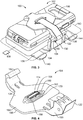
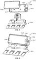
- Figure 1 is a perspective view of a connector system 100 in accordance with an exemplary embodiment in an open position.
- Figure 2 is a top view of the connector system 100 in accordance with an exemplary embodiment in a closed position.
- Figure 3 is a perspective view of the connector system 100 in accordance with an exemplary embodiment.
- the connector system 100 includes a receptacle connector assembly 102 and a plug connector assembly 104 that mate together to form an electrical and/or fiber optic connection therebetween.
- the plug connector assembly 104 is configured to be mounted to a user, such as to a wearable article 110 worn by the user, and the receptacle connector assembly 102 is removably coupled to the wearable article 110 by the plug connector assembly 104.
- the connector system 100 is provided along an electrical and/or fiber optic path between two electronic devices 106 and 108 for providing a separable electrical and/or fiber optic connection between the devices 106, 108.
- the connector system 100 is optionally mounted to any type of wearable article 110, such as, but not limited to, a vest, a shirt, a jacket, pants, trousers, a boot, a shoe, a helmet, a hat, a cap, a coat, armor, a backpack, and/or the like worn by an operator, such as military personnel, a first responder, and the like.
- the connector system 100 may form part of wearable technology, such as e-textiles.
- the connector system 100 may be configured to operate at any standard, protocol, and/or the like, such as, but not limited to, USB 1.0, USB 2.0, USB 3.0, CAN-BUS, GIGA-BIT ETHERNET, and/or the like.
- the connector system 100 may be scalable to a variety of different sizes.
- the connector system 100 is used to electrically connect a cell phone (first electronic device 106) with another component worn by the operator.
- the devices 106 and 108 each may be any type of electronic, fiber optic, and/or other type of device.
- the device 106 is a portable electronic device, such as a cell phone and the device 108 is a battery pack, a communication system, or another type of electronic device.
- Other types of devices may be interconnected by the connector system 100 in other embodiments.
- the receptacle connector assembly 102 includes a receptacle connector 112 ( Figure 2 ) and the plug connector assembly 104 includes a plug connector 114 ( Figure 2 ).
- the plug connector 114 is electrically connected to the receptacle connector 112 when the plug connector assembly 104 is mated with the receptacle connector assembly 102.
- the plug connector assembly 104 terminates one or more cables 122 of the wearable article 110.
- the cables 122 connect the plug connector assembly 104 to the device 108 and are worn by the operator.
- the cable 122 may be a round cable having one or more wires therein. In other various embodiments, the cable 122 may be a flat cable. In various embodiments, the cable 122 may be a flex circuit. In the illustrated embodiment, the cable 122 is separate from the wearable article 110; however the cable 122 may be embedded in the wearable article 110. In other embodiments, the cable 122 may be an e-textile.
- the plug connector assembly 104 is mounted to the wearable article 110.
- the wearable article 110 may be clothing, a mechanical device such as a clip or bracket worn by the user, an electrical device worn by the user, or another type of wearable article.
- the wearable article 110 may be a strap, belt or other component that supports the plug connector assembly 104.
- the wearable article 110 may be a backpack or other component carried by the operator.
- the plug connector assembly 104 includes a holder 130 supporting a housing 200 of the receptacle connector assembly 102.
- the holder 130 includes multiple pieces movable relative to each other.
- the holder 130 includes a support arm 134 and an article mount 136.
- the support arm 134 extends from the article mount 136.
- the support arm 134 is hingedly coupled to the article mount 136 at a hinge 138 of the holder 130.
- the article mount 136 is configured to be mounted to the wearable article 110.
- the article mount 136 may include a clip or other mounting structure configured to be secured to the wearable article 110.
- the support arm 134 may be pivoted to open and close the connector system 100, such as to access the electronic device 106 or restrict access to the electronic device 106, respectively.
- the support arm 134 is used to support the receptacle connector assembly 102 and/or the electronic device 106.
- the receptacle connector assembly 102 may be removably secured to the support arm 134, such as clipped into the support arm, latched to the support arm 134 or otherwise secured to the support arm 134.
- the support arm 134 supports the housing 200, which supports the electronic device 106.
- the support arm 134 holds the plug connector 114 and the housing 200 holds the receptacle connector 112. When the housing 200 is coupled to the support arm 134, the plug connector 114 is mated with the receptacle connector 112.
- the article mount 136 includes a base 140 used to secure the holder 130 to the wearable article 110.
- the base 140 may house or be part of an electronic device and the cable 122 may be electrically connected to the electronic device in the base 140.
- the base 140 may be released from the wearable article 110 to remove the plug connector assembly 104 from the wearable article 110.
- the article mount 136 may be integrated into the wearable article 110.
- the article mount 136 may be sown into one or more layers of the wearable article 110.
- the base 140 may be a patch or other element configured to be sown into the wearable article 110.
- the hinge 138 extends along a hinge axis 144.
- the support arm 134 is rotatably coupled to the article mount 136 at the hinge 138.
- the hinge 138 may include a cable channel 146 that receives the cable 122.
- the cable 122 is routed along the hinge 138 from the article mount 136 to the support arm 134.
- the cable 122 is protected in the cable channel 146, such as from snagging. Additionally, the cable 122 does not restrict opening and closing of the support arm 134 and does not bind when the support arm 134 is opened and closed.
- routing the cable 122 in the cable channel 146 prevents over bending of the cable 122 beyond a bend limit of the cable 122 by controlling routing of the cable 122 away from the plug connector 114.
- the cable 122 may be routed along the pivot axis (for example, parallel to the pivot axis). In other various embodiments, the cable 122 may extend across the hinge 138 between the support arm 134 and the article mount 136.
- FIG 4 is a perspective view of a portion of the plug connector assembly 104 showing the plug connector 114 in accordance with an exemplary embodiment.
- the plug connector 114 is provided on the support arm 134.
- the support arm 134 includes a base 150 and extends to a distal end 152.
- the support arm 134 includes a top 154 and a bottom 156.
- the plug connector 114 is provided on the top 154 between the base 150 and the distal end 152.
- the plug connector 114 may be provided at other locations in alternative embodiments.
- the plug connector 114 may be provided at the base 150 or at the distal end 152 in alternative embodiments.
- the plug connector 114 may be provided on the bottom 156 in various embodiments.
- the support arm 134 is generally C-shaped and defines a channel that receives the receptacle connector assembly 102.
- the support arm 134 may define a clip that receives the receptacle connector assembly 102.
- the plug connector 114 may accommodate pivoted or rotated mating into the support arm 134 by the receptacle connector assembly 102.
- the plug connector 114 is separate and discrete from the support arm 134 and coupled thereto.
- the plug connector 114 may be integral with and defined by the support arm 134.
- the support arm 134 may be molded to form the plug connector 114.
- the plug connector 114 includes a shroud 158 extending from the top 154 of the support arm 134.
- the shroud 158 defines a plug configured to be plugged into the receptacle connector 112.
- the plug connector 114 includes plug contacts 160 at a mating interface configured to be mated with the receptacle connector 112.
- the plug contacts 160 are configured to be electrically connected to the receptacle connector 112.
- the plug contacts 160 are electrically connected to the cable 122.
- the plug connector 114 includes a printed circuit board and the plug contacts 160 are terminated to the printed circuit board (for example, soldered or press-fit) and the cable 122 is terminated to the printed circuit board (for example, soldered). In other various embodiments, the plug contacts 160 are terminated directly to the cable 122. In an exemplary embodiment, the plug contacts 160 include spring beams being deflectable and configured for mating with the receptacle connector 112. Other types of contacts may be provided in alternative embodiments, such as Pogo pins, pads, and the like. In other various embodiments, the plug connector 114 may include a circuit board having circuits defining the plug contacts 160. In other various embodiments, the plug connector 114 may be provided without the printed circuit board, such as including stamped and formed contacts that are overmolded or loaded into a pre-molded contact holder.
- the plug connector 114 has space around the plug contacts 160 that allows removal of dirt and debris from the plug contacts 160.
- a tool or cloth may be used to clean or wipe the plug contacts 160.
- the plug connector 114 may be open below the plug contacts 160 to allow the dirt and debris to be ejected through the bottom such that the dirt and debris does not gather in the plug connector 114.
- the shroud 158 may be closed off, such as using a cap or cover, around the plug contacts 160 to limit ingress of dirt or debris into the shroud and the exposed mating ends of the plug contacts 160 are configured to be wiped clean at the top surface of the plug connector 114.
- the plug connector 114 includes an electrical shield 162 at least partially surrounding the plug contacts 160.
- the electrical shield 162 provides electrical shielding for the plug contacts 160 at the mating interface.
- the electrical shield 162 may be a machined, diecast, or stamped and formed shield coupled to the support arm 134 and/or the shroud 158.
- the electrical shield 162 is defined by conductive plating provided on the support arm 134 and/or the shroud 158 rather than a separate machined part.
- the plug connector 114 has a seal surface 164 that may be sealed to provide a sealed interface with the receptacle connector 112.
- the seal surface 164 is defined on the exterior of the shroud 158.
- the plug connector assembly 104 includes a seal 170 at the seal surface 164.
- the seal 170 surrounds the plug contacts 160 to provide a sealed mating interface for mating with the receptacle connector assembly 102.
- the seal 170 may be a perimeter seal extending entirely around the perimeter of the mating interface.
- the seal 170 may be an interface seal on the support arm 134.
- the seal 170 may be a rubber gasket.
- the seal 170 may be provided on the receptacle connector assembly 102 rather than the plug connector assembly 104.
- the plug connector assembly 104 may include a latching feature (not shown) for latchably securing the plug connector assembly 104 to the receptacle connector assembly 102.
- the plug connector assembly 104 may include a release mechanism (not shown), such as a push button or a pull tab to release the latching feature from the receptacle connector assembly 102, such as for releasing the receptacle connector assembly 102 from the plug connector assembly 104.
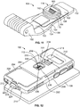
- FIG. 5 is a rear perspective view of the receptacle connector assembly 102 in accordance with an exemplary embodiment.
- Figure 6 is a cross-sectional view of a portion of the receptacle connector assembly 102 in accordance with an exemplary embodiment.
- the receptacle connector assembly 102 includes the housing 200 that receives the first electronic device 106.
- the first electronic device 106 may be held in a case and the housing 200 may receive the first electronic device 106 and the case.
- the housing 200 includes a top 202 and a bottom 204 opposite the top 202.
- the housing 200 includes a first side 206 and a second side 208 opposite the first side 206.
- the housing 200 includes a first end 210 and a second end 212 opposite the first end 210.
- the housing 200 includes a cavity 214 that receives the electronic device 106.
- the cavity 214 may be open at the top 202 (for example, see Figure 1 ) and/or the first end 210 for receiving the electronic device 106.
- the cavity 214 is open at the top 202 to access the electronic device 106 when the electronic device 106 is received in the housing 200.
- the electronic device 106 is a cell phone and the touchscreen of the cell phone is accessible through the top 202.
- the housing 200 includes a window 216 at the bottom 204.
- the window 216 provides access to the electronic device 106.
- the window 216 may provide access for a camera, a flash a light, or another feature of the electronic device 106.
- the receptacle connector assembly 102 includes a connector assembly 220 providing an electrical interface between the plug connector assembly 104 and the electronic device 106.
- the connector assembly 220 includes the receptacle connector 112.
- the receptacle connector 112 includes a printed circuit board 222; however, the receptacle connector 112 may include other electrical components, such as a flexible circuit, contacts, and the like.
- the connector assembly 220 includes a mating connector 224 and a cable 226 connecting the printed circuit board 222 and the mating connector 224.
- the cable 226 may be a jacketed cable having one or more wires therein. Alternatively, the cable 226 may be a flat cable, such as a flex circuit.
- the mating connector 224 may be mounted directly to the printed circuit board 222.
- the mating connector 224 has a mating interface for electrical connection with the electronic device 106, such as a cell phone interface, a USB interface, and the like.
- the printed circuit board 222 may include circuitry and/or electrical components for processing signals and/or power between the cable 122 and the electronic device 106.
- the printed circuit board 222 includes receptacle contacts 228 defining a mating interface 230 for mating with the plug connector assembly 104.
- the receptacle contacts 228 may be defined by circuits, such as pads, traces or vias on the printed circuit board 222.
- the receptacle contacts 228 may be spring contacts or other types of contacts terminated to the printed circuit board 222.
- the housing 200 may hold a mating connector for mating with the plug connector assembly 104.
- the housing 200 includes a receptacle 232 at the bottom 204 for receiving the plug connector 114 of the plug connector assembly 104.
- the receptacle 232 is defined by sidewalls 234.
- the receptacle 232 is open at the bottom 204 of the housing 200 for rear loading the plug connector 114 into the receptacle 232 in a direction generally perpendicular to the cavity 214.
- the receptacle 232 is open at the first side 206 of the housing 200 for side loading the plug connector 114 into the receptacle 232 in a direction generally parallel to the cavity 214.
- the receptacle 232 may be located at other positions and/or in other orientations in alternative embodiments.
- the sidewalls 234 may be angled to provide lead-in and guidance for mating with the plug connector 114.
- the sidewalls 234 may provide a large catch window to allow pivoting mating of the plug connector 114 into the receptacle 232 and ensure alignment of the connectors when fully mated.
- the housing 200 includes an opening 236 that provides access to the printed circuit board 222.
- the contacts 228 are exposed in the opening 236 for mating with the plug connector assembly 104.
- the sidewalls 234 define a seal surface 238 configured to engage the seal 170 (shown in Figure 3 ).
- the receptacle 232 may include a lead-in to guide the plug connector 114 into the receptacle 232 during mating.
- the lead-in makes blind mating of the receptacle connector assembly 102 with the plug connector assembly 104 easier and may accommodate pivoting or mating at various angles.
- the receptacle connector assembly 102 may include other alignment features or guide features to guide mating with the plug connector assembly 104.
- the receptacle connector assembly 102 may include a latching feature (not shown) for interfacing with the plug connector assembly 104 to secure the plug connector assembly 104 to the receptacle connector assembly 102.
- Figure 7 is a cross-sectional view of the connector system 100 in accordance with an exemplary embodiment.
- Figure 8 is a cross-sectional view of the connector system 100 in accordance with an exemplary embodiment.
- Figures 7 and 8 illustrate the plug connector 114 mated with the receptacle connector 112.
- the plug connector 114 is plugged into the receptacle 232 and electrically connected with the receptacle connector 112.
- the plug contacts 160 are mated with the receptacle contacts 228.
- the seal surface 238 of the receptacle connector assembly 102 engages the seal 170.
- the seal 170 is compressed against the edge 236 to seal the mating interface.
- the sidewalls 234 are angled to guide loading of the plug connector 114 into the receptacle 232.
- the leading edge of the shroud 158 may be angled for mating with the receptacle connector 112.
- Figure 9 is a cross-sectional view of the connector system 100 in accordance with an exemplary embodiment showing the receptacle connector assembly 102 and the plug connector assembly 104.
- the housing 200 is shown coupled to the holder 130.
- the plug connector 114 is shown connected to the receptacle connector 112.
- the cable 122 is routed from the plug connector 114, along the hinge 138 to the article mount 136.
- the cable 122 is terminated to a second plug connector 180 held by the base 140.
- the second plug connector 180 may be similar to or identical to the plug connector 114.
- the second plug connector 180 is configured to be mated with a receptacle connector 182.
- the receptacle connector 182 is part of a removable element 184 of the article mount 136.
- the removable element 184 may be an electronic device, such as a battery, a communication system or another electronic device.
- the removable element 184 may include electronics electrically connected to the receptacle connector 182.
- Figure 10 is a perspective view of a portion of the holder 130 showing the base 140 without the removable element 184.
- the base 140 holds the plug connector 180.
- the base 140 forms part of the hinge 138.
- FIG 11 is a top perspective view of a portion of the plug connector assembly 104 in accordance with an exemplary embodiment.
- the support arm 134 and the plug connector 114 illustrated in Figure 11 are similar to those illustrated in Figure 4 .
- the support arm 134 illustrated in Figure 11 is shaped differently than the support arm 134 illustrated in Figure 4 and the plug connector 114 illustrated in Figure 11 is shaped differently than the plug connector 114 illustrated in Figure 4 .
- the support arm 134 is L shaped rather than being C-shaped.
- the shroud 158 of the plug connector 114 is taller and configured to be plugged deeper into a receptacle.
- the shroud 158 of the plug connector 114 supports a taller seal 170 configured to be sealed in a different manner than the seal 170 shown in Figure 4 .
- Figure 12 is a rear perspective view of a portion of the receptacle connector assembly 102 in accordance with an exemplary embodiment.
- the receptacle connector 112 illustrated in Figure 12 is similar to the receptacle connector 112 illustrated in Figure 5 ; however, the receptacle connector 112 illustrated in Figure 12 is sized and shaped for mating with the plug connector 112 shown in Figure 11 .
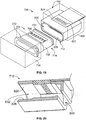
- FIG 13 illustrates a connector system 300 in accordance with an exemplary embodiment.
- the connector system 300 is similar to the connector system 100 (shown in Figure 1 ) and includes a receptacle connector assembly 302 and a plug connector assembly 304 that mate together to form an electrical and/or fiber optic connection therebetween.
- the receptacle connector assembly 302 and the plug connector assembly 304 mate differently than the embodiment illustrated in Figure 1 .
- the receptacle connector assembly 302 and the plug connector assembly 304 are side mated rather than being rear mated and are shaped and located for such mating; however, the connector assemblies 302, 304 includes similar components as the connector assemblies 102, 104.
- the receptacle connector assembly 302 includes a receptacle connector 312 and the plug connector assembly 304 includes a plug connector 314.
- the plug connector 314 is electrically connected to the receptacle connector 312 when the plug connector assembly 304 is mated with the receptacle connector assembly 302.
- the plug connector 314 is provided on a support arm 334, which may be similar to the support arm 134.
- the support arm 334 includes a base 350. In the illustrated embodiment, the plug connector 314 is provided on the base 350.
- the plug connector 314 includes a base 356 and a platform 358 extending from the base 356.
- the platform 358 defines a plug configured to be plugged into the receptacle connector 312.
- the plug connector 314 includes plug contacts 360 at a mating interface configured to be mated with the receptacle connector 312.
- the plug contacts 360 extend along the platform 358.
- the plug contacts 360 may extend into the base 356 and/or into the base 350 for termination to the cable.
- the plug contacts 360 include spring beams being deflectable and configured for mating with the receptacle connector 312. Other types of contacts may be provided in alternative embodiments, such as Pogo pins, pads, and the like.
- the plug connector 314 may include a circuit board having circuits defining the plug contacts 360.
- the plug connector 314 has space around the plug contacts 360 that allows removal of dirt and debris from the plug contacts 360.
- the platform 358 may include openings 366 around the plug contacts 360 that allow removal of the dirt from around the plug contacts 360.
- a tool or cloth may be used to clean or wipe the plug contacts 360.
- the plug connector 314 may be open below the plug contacts 360 to allow the dirt and debris to be ejected through the bottom such that the dirt and debris does not gather in the plug connector 314.
- the plug connector 314 includes an electrical shield 362 at least partially surrounding the plug contacts 360.
- the electrical shield 362 provides electrical shielding for the plug contacts 360 at the mating interface.
- the electrical shield 362 may be a machined, diecast, or stamped and formed shield. In alternative embodiments, the electrical shield 362 is defined by conductive plating.
- the plug connector 314 has a seal surface 364 that may be sealed to provide a sealed interface with the receptacle connector 312.
- the seal surface 364 is defined on the base 356 rearward of the platform 358.
- the plug connector assembly 304 includes a seal 370 at the seal surface 364.
- the platform 358 is cantilevered forward of the seal 370.
- the seal 370 provides a sealed mating interface for mating with the receptacle connector assembly 302.
- the seal 370 is configured to be engaged by the receptacle connector assembly 302.
- the seal 370 may be a rubber gasket.
- the seal 370 may be provided on the receptacle connector assembly 302 rather than the plug connector assembly 304.
- the receptacle connector assembly 302 includes a housing 400 that receives the first electronic device 306.
- the housing 400 may be similar to the housing 200 (shown in Figure 1 ).
- the housing 400 includes a top 402 and a bottom 404 opposite the top 402.
- the housing 400 includes a first side 406 between the top 402 and the bottom 404.
- the housing 400 includes a cavity 414 that receives the electronic device 306.
- the receptacle connector assembly 302 includes a connector assembly 420 providing an electrical interface between the plug connector assembly 304 and the electronic device 306.
- the connector assembly 420 includes the receptacle connector 312.
- the receptacle connector 312 includes a printed circuit board 422; however, the receptacle connector 312 may include other electrical components, such as a flexible circuit, contacts, and the like.
- the printed circuit board 422 includes receptacle contacts 428 defining a mating interface 430 for mating with the plug connector assembly 304.
- the receptacle contacts 428 may be defined by circuits, such as pads, traces or vias on the printed circuit board 422.
- the receptacle contacts 428 may be spring contacts or other types of contacts terminated to the printed circuit board 422.
- the housing 400 includes a receptacle 432 at the bottom 404 for receiving the plug connector 314 of the plug connector assembly 304.
- the receptacle 432 is defined by sidewalls 434 extending to edges 436.
- the receptacle 432 is open at the first side 406 of the housing 400 for side loading the plug connector 314 into the receptacle 432 in a direction generally parallel to the cavity 414.
- the receptacle 432 may be located at other positions and/or in other orientations in alternative embodiments.
- the edges 436 define a seal surface 438 configured to engage the seal 370 when the plug connector assembly 104 is coupled to the receptacle connector assembly 102.
- Figure 14 is a cross-sectional view of the connector system 300 showing the plug connector assembly 304 mated with the receptacle connector assembly 302.
- the plug connector 314 When mated, the plug connector 314 is electrically connected with the receptacle connector 312.
- the plug contacts 360 are mated with the receptacle contacts 428.
- the seal surface 438 of the receptacle connector assembly 302 engages the seal 370.
- the seal 370 is compressed against the edge 436 to seal the mating interface.
- Figure 15 illustrates the connector system 300 in accordance with an exemplary embodiment.
- the mating interface between the receptacle connector 312 and the plug connector 314 are angled rather than being vertical.
- the angled mating interface provides greater access to the plug contacts 360 and the receptacle contacts 428 for cleaning the plug contacts 360 and the receptacle contacts 428.
- the angled mating interface enlarges the area of the receptacle providing greater access to the receptacle to clean out debris from the receptacle.
- Figure 16 is a cross-sectional view of the connector system 300 showing the plug connector assembly 304 mated with the receptacle connector assembly 302.
- the plug connector 314 When mated, the plug connector 314 is electrically connected with the receptacle connector 312.
- the plug contacts 360 are mated with the receptacle contacts 428 at the angled mating interface.
- the seal surface 438 of the receptacle connector assembly 302 engages the seal 370 at the angled mating interface.
- the seal 370 is compressed against the edge 436 to seal the mating interface.
- FIG 17 illustrates a connector system 500 in accordance with an exemplary embodiment.
- the connector system 500 is similar to the connector system 300 (shown in Figure 13 ) and includes a receptacle connector assembly 502 and a plug connector assembly 504 that mate together to form an electrical and/or fiber optic connection therebetween.
- the receptacle connector assembly 502 and the plug connector assembly 504 are similar to the receptacle connector assembly 302 and the plug connector assembly 304; however the mating interfaces and contacts are different.
- the receptacle connector assembly 502 includes a receptacle connector 512 and the plug connector assembly 504 includes a plug connector 514.
- the plug connector 514 is electrically connected to the receptacle connector 512 when the plug connector assembly 504 is mated with the receptacle connector assembly 502.
- the plug connector 514 includes a printed circuit board 558 having plug contacts 560 defined by circuits of the printed circuit board 558.
- the receptacle connector 512 includes receptacle contacts 562 defined by spring beams configured to be mated to the printed circuit board 558 when the plug connector 514 is plugged into the receptacle connector 512.
- Figure 18 is a cross-sectional view of the connector system 500 showing the plug connector assembly 504 mated with the receptacle connector assembly 502.
- the plug connector 514 When mated, the plug connector 514 is electrically connected with the receptacle connector 512.
- the printed circuit board 558 is plugged into the receptacle connector 512.
- the plug contacts 560 are mated with the receptacle contacts 562.
- a seal surface 564 of the receptacle connector assembly 502 engages a seal 570.
- the seal 570 is compressed against the edge of the receptacle connector 512 to seal the mating interface.
- FIG 19 illustrates a connector system 700 in accordance with an exemplary embodiment.
- the connector system 700 is similar to the connector system 100 (shown in Figure 1 ) and includes a receptacle connector assembly 702 and a plug connector assembly 704 that mate together to form an electrical and/or fiber optic connection therebetween.
- the receptacle connector assembly 702 and the plug connector assembly 704 are similar to the receptacle connector assembly 102 and the plug connector assembly 104; however the mating interfaces and contacts are different.
- the receptacle connector assembly 702 includes a receptacle connector 712 and the plug connector assembly 704 includes a plug connector 714.
- the plug connector 714 is electrically connected to the receptacle connector 712 when the plug connector assembly 704 is mated with the receptacle connector assembly 702.
- the plug connector 714 is configured to be mounted to a holder 730.
- the plug connector includes seals 770, 772 along a plug shroud 758. Plug contacts 760 are arranged along the plug shroud 758.
- the receptacle connector 712 includes a receptacle 832 configured to be coupled to or formed in a housing 800.
- the receptacle 832 holds a printed circuit board 822 having receptacle contacts 824.
- the receptacle 832 receives the plug connector 714.
- Interior surfaces of the receptacle 832 define seal surfaces 826 of the receptacle connector 712.
- FIG 20 is a cross-sectional view of the receptacle connector 712 in accordance with an exemplary embodiment.
- the receptacle 832 includes an opening or window 840 and a back end of the receptacle 832.
- the plug connector 714 may force debris out of the receptacle 832 through the opening 840.
- the seals 770, 772 may seal against the seal surfaces 826.
- the seals 770, 772 may wipe against the seal surfaces 826 to clean the debris from the receptacle 832.
- FIG 21 is a cross-sectional view of a connector system 900 in accordance with an exemplary embodiment.
- the connector system 900 is similar to the connector system 100 (shown in Figure 1 ) and includes a receptacle connector assembly 902 and a plug connector assembly 904 that mate together to form an electrical and/or fiber optic connection therebetween.
- the receptacle connector assembly 902 and the plug connector assembly 904 are similar to the receptacle connector assembly 102 and the plug connector assembly 104; however the mating interfaces and contacts are different.
- the receptacle connector assembly 902 includes a receptacle connector 912 and the plug connector assembly 904 includes a plug connector 914.
- the plug connector 914 is electrically connected to the receptacle connector 912 when the plug connector assembly 904 is mated with the receptacle connector assembly 902.
- the plug connector 914 is configured to be mounted to a holder 930.
- the plug connector 914 includes a plug shroud 958 having plug contacts 960 along a top of the plug shroud 958. The top of the plug shroud 958 defines a seal surface 962.
- the receptacle connector 912 includes a receptacle 1032 configured to be coupled to or formed in a housing 1000.
- the receptacle 1032 holds a receptacle assembly 1034 including a printed circuit board 1022 and a seal 1020.
- the seal 1020 may be a perimeter seal that surrounds the printed circuit board 1022.
- the plug connector 914 is coupled to the receptacle connector 912 to interface with the printed circuit board 1022 and the seal 1020, such as from the bottom of the receptacle connector 912.
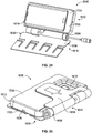
- FIG 22 is a perspective view of an exemplary embodiment of a connector system 1610 in accordance with an exemplary embodiment.
- the connector system 1610 may be similar to the connector system 100 (shown in Figure 1 ).
- the connector system 1610 includes a receptacle connector assembly 1612 and a plug connector assembly 1614 that mate together to form an electrical and/or fiber optic connection therebetween.
- the receptacle connector assembly 1612 may be similar to the receptacle connector assembly 102 shown in Figure 1 and the plug connector assembly 1614 may be similar to the plug connector assembly 104 shown in Figure 1 and may include similar components and features, respectively.
- the connector system 1610 is provided along an electrical and/or fiber optic path between two electronic devices 1616 and 1618 for providing a separable electrical and/or fiber optic connection between the devices.
- the connector system 1610 is optionally mounted to any type of wearable article 1620, such as, but not limited to, a vest, a shirt, a jacket, pants, trousers, a boot, a shoe, a helmet, a hat, a cap, a coat, armor, and/or the like worn by an operator, such as military personnel, a first responder, and the like utilizing wearable technology, such as e-textiles.
- the connector system 1610 may be configured to operate at any standard, protocol, and/or the like, such as, but not limited to, USB 1.0, USB 2.0, USB 3.0, CAN-BUS, GIGA-BIT ETHERNET, and/or the like.
- the connector system 1610 may be scalable to a variety of different sizes.
- the connector system 1610 is used to electrically connect a cell phone (first electronic device 1616) with another component worn by the operator.
- the devices 1616 and 1618 each may be any type of electronic, fiber optic, and/or other type of device.
- the device 1616 is a portable electronic device, such as a cell phone and the device 1618 is a battery pack.
- Other types of devices may be interconnected by the connector system 1610 in other embodiments.
- the plug connector assembly 1614 terminates one or more cables 1622 of the wearable article 1620.
- the cables 1622 connect the plug connector assembly 1614 to the device 1618 and are worn by the operator.
- the cable 1622 is separate from the wearable article 1620; however the cable 1622 may be embedded in the wearable article 1620.
- the cable 1622 may be an e-textile that includes embedded electrical fabrics that enable computing, digital components, electrical pathways, fiber optic pathways, and/or electronic and/or fiber optic devices to be embedded therein.
- the e-textile provides the wearable article 1620 with wearable technology that allows for the incorporation of built-in technological elements into the fabric of the wearable article 1620.
- the wearable article 1620 may constitute intelligent clothing or smart clothing.
- the plug connector assembly 1614 is mounted to the wearable article 1620.
- the wearable article 1620 may be clothing.
- the wearable article 1620 may be a strap, belt or other component that supports the plug connector assembly 1614.
- the wearable article 1620 may be a backpack or other component carried by the operator.
- the plug connector assembly 1614 includes a holder 1630 supporting a connector housing 1632 having a mating interface for mating with the receptacle connector assembly 1612.
- the holder 1630 includes multiple pieces movable relative to each other.
- the holder 1630 includes a support arm 1634 and an article mount 1636 hingedly coupled to the support arm 1634 at a hinge 1638.
- the article mount 1636 may be a clip configured to be mounted to the wearable article 1620.
- the support arm 1634 supports the connector housing 1632.
- the support arm 1634 and the connector housing 1632 may be integral with each other.
- the connector housing 1632 may be separate and discrete from the support arm 1634 and mounted or secured to the support arm 1634.
- the article mount 1636 includes a base 1640 and clipping fingers 1642 movable relative to the base 1640.
- the clipping fingers 1642 are used to secure the holder 1630 to the wearable article 1620.
- the base 1640 in the clipping fingers 1642 may be released from the wearable article 1620 to remove the plug connector assembly 1614 from the wearable article 1620.
- the article mount 1636 may be integrated into the wearable article 1620.
- the article mount 1636 may be sown into one or more layers of the wearable article 1620.
- the hinge 1638 extends along a hinge axis 1644.
- the support arm 1634 is rotatably coupled to the article mount 1636 at the hinge 1638.
- the hinge 1638 may be hollow and define a cable channel 1646 that receives the cable 1622.
- the cable 1622 is routed along the hinge axis 1644.
- the cable 1622 is protected and the cable channel 1646, such as from snagging.
- the cable 1622 does not restrict opening and closing of the support arm 1634 and does not bind when the support arm 1634 is opened and closed. Additionally, routing the cable 1622 and the cable channel 1646 prevents over bending of the cable 1622 beyond a bend limit of the cable 1622 by controlling routing of the cable 1622 away from the connector housing 1632.
- the connector housing 1632 includes sidewalls 1650 extending from the support arm 1634 to a mating surface 1652.
- the mating surface 1652 may be planar.
- the mating surface 1652 may be oriented parallel to the support arm 1634.
- the mating surface 1652 may be angled relative to the support arm 1634 for mating with the receptacle connector assembly 1612.
- the sidewalls 1650 include shoulders 1654 spaced apart from and facing the support arm 1634. Channels are defined between the shoulders 1654 and the support arm 1634 that receive a portion of the receptacle connector assembly 1612 to secure the receptacle connector assembly 1612 to the plug connector assembly 1614.
- portions of the sidewalls 1650 may be angled such that the connector housing 1632 is narrower at the front and wider at the rear of the connector housing 1632, such as to provide lead-in during mating with the receptacle connector assembly 1612.
- the connector housing 1632 includes a cable guide 1656 extending rearward from the connector housing 1632.
- the cable guide 1656 guides the cable 1622 from the connector housing 1632.
- the cable guide 1656 guides the cable 1622 to the cable channel 1646.
- the plug connector assembly 1614 includes plug contacts 1660 at the mating surface 1652.
- the plug contacts 1660 and the connector housing 1632 define a plug connector 1658 of the plug connector assembly 1614 configured to be mated with a receptacle connector of the receptacle connector assembly 1612.
- the plug contacts 1660 are configured to be electrically connected to the receptacle connector assembly 1612.
- the plug contacts 1660 are electrically connected to the cable 1622.
- the plug contacts 1660 include spring beams being deflectable and configured for mating with the receptacle connector assembly 1612. Other types of contacts may be provided in alternative embodiments, such as Pogo pins, pads, and the like.
- the plug connector assembly 1614 includes a seal 1670 at the mating surface 1652.
- the seal 1670 surrounds the plug contacts 1660 to provide a sealed mating interface for mating with the receptacle connector assembly 1612.
- the seal 1670 is a perimeter seal extending entirely around the perimeter of mating interface.
- the seal 1670 may be a rubber gasket. In an alternative embodiment, the seal 1670 may be provided on the receptacle connector assembly 1612 rather than the plug connector assembly 1614.
- the plug connector assembly 1614 includes a latching feature 1680 for latchably securing the plug connector assembly 1614 to the receptacle connector assembly 1612.
- the latching feature 1680 is a deflectable latch having a latching surface 1682.
- the plug connector assembly 1614 may include a release mechanism, such as a push button or a pull tab to release the latching feature 1680 from the receptacle connector assembly 1612, such as for releasing the receptacle connector assembly 1612 from the plug connector assembly 1614.
- the receptacle connector assembly 1612 includes a housing 1700 configured to receive the first electronic device 1616.
- the housing 1700 includes a top 1702 and a bottom 1704 opposite the top 1702.
- the housing 1700 includes a first side 1706 and a second side 1708 opposite the first side 1706.
- the housing 1700 includes a first end 1710 and a second end 1712 opposite the first end 1710.
- the housing 1700 includes a cavity 1714 that receives the electronic device 1616.
- the cavity 1714 may be open at the top 1702 and/or the first end 1710 for receiving the electronic device 1616.
- the cavity 1714 is open at the top 1702 to access the electronic device 1616 when the electronic device 1616 is received in the housing 1700.
- the electronic device 1616 is a cell phone and the touchscreen of the cell phone is accessible through the top 1702.
- the housing 1700 includes a window 1716 at the bottom 1704.
- the window 1716 provides access to the electronic device 1616.
- the window 1716 may provide access for a camera, a flash or another feature of the electronic device 1616.
- the receptacle connector assembly 1612 includes a connector assembly 1720 providing an electrical interface between the plug connector assembly 1614 and the electronic device 1616.
- the connector assembly 1720 includes a receptacle connector 1718 including a printed circuit board 1722, a mating connector 1724 and a cable 1726 connecting the printed circuit board 1722 and the mating connector 1724.
- the receptacle connector 1718 is configured to be electrically connected to the plug connector 1658.
- the cable 1726 may be a jacketed cable having one or more wires therein. Alternatively, the cable 1726 may be a flat cable, such as a flex circuit.
- the mating connector 1724 may be mounted directly to the printed circuit board 1722.
- the mating connector 1724 has a mating interface for electrical connection with the electronic device 1616, such as a cell phone interface, a USB interface, and the like.
- the printed circuit board 1722 may include circuitry and/or electrical components for processing signals and/or power between the cable 1622 and the electronic device 1616.
- the printed circuit board 1722 includes contacts 1728 defining a mating interface 1730 for mating with the plug connector assembly 1614.
- the contacts 1728 may be pads on the printed circuit board 1722.
- the contacts 1728 may be spring contacts or other types of contacts terminated to the printed circuit board 1722.
- the housing 1700 may hold a mating connector for mating with the plug connector assembly 1614.
- the housing 1700 includes a plug channel 1732 at the bottom 1704 for receiving the connector housing 1632 of the plug connector assembly 1614.
- the plug channel 1732 is defined by sidewalls 1734.
- the plug channel 1732 is open at the first side 1706 of the housing 1700 to receive the connector housing 1632 in a side loading direction.
- the loading direction may be perpendicular to the mating direction of the contacts 1728 with the plug contacts 1660.
- the housing 1700 includes an opening 1736 that provides access to the printed circuit board 1722.
- the contacts 1728 are exposed in the opening 1736 for mating with the plug connector assembly 1614.
- the sidewalls 1734 include lips 1738 having channels above the lips 1738 that receive portions of the plug connector assembly 1614 for securing the plug connector assembly 1614 in the plug channel 1732.
- the lips 1738 are configured to engage the shoulders 1654 to secure the connector housing 1632 in the plug channel 1732.
- the plug channel 1732 includes a lead-in 1740 to guide the connector housing 1632 into the plug channel 1732.
- the plug channel 1732 is wider at the lead-in 1740 and narrower at the mating interface 1730.
- the lead-in 1740 makes blind mating of the receptacle connector assembly 1612 with the plug connector assembly 1614 easier.
- the receptacle connector assembly 1612 includes a latching feature 1742 for interfacing with the latching feature 1680 of the plug connector assembly 1614 to secure the plug connector assembly 1614 to the receptacle connector assembly 1612.
- the latching feature 1742 is a catch surface defined by the opening 1736.
- Other types of latching features 1742 may be used in alternative embodiments.
- the latching features 1742, 1680 allow the receptacle connector assembly 1612 to clip onto the holder 1630 of the plug connector assembly 1614. When the latching features 1742, 1680 latchably couple, the plug contacts 1660 are mated to the contacts 1728 to create an electrical connection between the receptacle connector assembly 1612 and the plug connector assembly 1614.
- Figure 24 is a perspective view of the connector system 1610 showing the receptacle connector assembly 1612 coupled to the plug connector assembly 1614 and showing the connector system 1610 in an open position.
- Figure 25 is a perspective view of the connector system 1610 showing the receptacle connector assembly 1612 coupled to the plug connector assembly 1614 and showing the connector system 1610 in a closed position.
- the holder 1630 is rotated at the hinge 1638 to open the support arm 1634 relative to the article mount 1636.
- the electronic device 1616 is accessible.
- the touchscreen of the cell phone may be accessed through the top 1702 of the housing 1700 of the receptacle connector assembly 1612.
- the electronic device 1616 may be an accessible or inaccessible, such as being closed against the article mount 1636.
- the connector system 1610 may be closed to protect the electronic device 1616.
- Figure 26 is an exploded view of the connector system 1610 in accordance with an exemplary embodiment.
- Figure 27 is a perspective view of the connector system 1610 showing the receptacle connector assembly 1612 mated with the plug connector assembly 1614 in the open position.
- the electronic device 1616 includes a case 1617 receiving the electronic device 1616.
- the case 1617 may protect the electronic device 1616.
- the case 1617 and the electronic device 1616 are configured to be loaded into the cavity 1714 of the housing 1700 of the receptacle connector assembly 1612.
- the receptacle connector assembly 1612, including the case 1617 and the electronic device 1616 are configured to be mated with the plug connector assembly 1614.
- Figure 28 is an exploded view of the connector system 1610 in accordance with an exemplary embodiment.
- Figure 29 is a perspective view of the connector system 1610 showing the receptacle connector assembly 1612 mated with the plug connector assembly 1614 in the open position.
- the electronic device 1616 includes the case 1617 used to protect the electronic device 1616.
- the case 1617 is mounted to the housing 1700, such as using fasteners 1750, and the electronic device 1616 is configured to be loaded into and removed from the case 1617 without removing the case 1617 from the housing 1700.
- the case 1617 defines the cavity 1714 of the receptacle connector assembly 1612 that receives the electronic device 1616.
- the receptacle connector assembly 1612, including the case 1617 and the electronic device 1616 are configured to be mated with the plug connector assembly 1614.
Landscapes
- Engineering & Computer Science (AREA)
- Microelectronics & Electronic Packaging (AREA)
- Connector Housings Or Holding Contact Members (AREA)
- Details Of Connecting Devices For Male And Female Coupling (AREA)
Abstract
Description
- The subject matter described and/or illustrated herein relates generally to electrical connectors for wearable articles.
- Connectors are sometimes integrated into clothing, apparel, and/or other wearable articles worn by an individual in a variety of different applications, such as, but not limited to, first responders (e.g. fire and police), maintenance technicians, soldiers, and/or the like. Known connectors that are integrated into wearable articles are not without problems. For example, in some environments, such as when the connectors are being used outside or in other harsh environments, contaminants such as dirt, mud, grease, sand, and/or other debris, and/or fluids such as water and/or oil may get trapped within a receptacle connector. Contaminants may enter the receptacle while the receptacle connector is disconnected from the complementary plug connector, or while the connectors are mated if the mating interface is not sealed. Such contaminants may contaminate the mating interface of the connector and/or otherwise impede mating of the plug and receptacle connectors, which for example may interrupt the electrical connection and/or damage the connector(s). Removal of such contaminants may be difficult and/or time consuming. For example, it may be difficult to clean the mating interface of a connector in the field. Moreover, attempting to clean the mating interface of a connector may damage of the conductors of the connector. For example, using tools, fingers, thumbs, cloths, and/or the like to remove the contaminants may damage the conductors. Some contaminants may be permanently trapped beneath the conductors of a connector.
- Additionally, wearable connectors are typically subjected to harsh environments, such as wet and dirty environments. Sealing of the connectors is difficult. Electrical shielding of the connectors may be problematic.
- A need remains for reliable electrical connectors for wearable articles.
- The solution is provided by a connector system for a wearable article including a receptacle connector assembly and a plug connector assembly mated to the receptacle connector assembly. The receptacle connector assembly includes a housing having a cavity configured to removably receive an electronic device. The receptacle connector assembly has a receptacle connector configured to be electrically connected to the electronic device when received in the cavity. The receptacle connector has a receptacle and receptacle contacts in the receptacle being electrically connecting to the electronic device. The receptacle connector has a seal surface. The plug connector assembly includes a holder including an article mount configured to be secured to the wearable article and a support arm hingedly coupled to the article mount at a hinge of the holder. The plug connector assembly has a plug connector on the support arm including plug contacts and a seal surface. The plug connector has a cable electrically connected to the plug contacts and extending from the plug connector or from the holder or from a connector housing of the plug connector assembly. A seal is coupled to one of the receptacle connector or the plug connector at the corresponding seal surface and engages the other of the receptacle connector and the plug connector at the corresponding seal surface. The plug connector is loaded into the receptacle of the receptacle connector to mate the plug contacts with the receptacle contacts to electrically connect the cable to the electronic device through the plug contacts and the receptacle contacts.
- Optionally, the plug connector may include a plug shroud surrounding the plug contacts and the seal may be a perimeter seal surrounding an exterior of the plug shroud. The plug connector may include a base and a platform extending from the platform with the contacts extending along the platform and the base holding the seal. The receptacle connector may have a mating edge defining the seal surface configured to engage the seal when the platform is plugged into the receptacle.
- Optionally, the plug connector is mated to the receptacle connector in a mating direction. The plug connector may have an angled mating interface angled transverse to the mating direction. The receptacle connector may have an angled mating interface angled transverse to the mating direction.
- Optionally, the receptacle connector may include a printed circuit board in the receptacle having circuits defining the receptacle contacts. The plug contacts may have spring beams configured to be spring biased against the receptacle contacts. Optionally, the plug connector may include a printed circuit board having circuits defining the plug contacts configured to be plugged into the receptacle. The receptacle contacts may have spring beams configured to be spring biased against the plug contacts.
- Optionally, at least one of the plug connector and the receptacle connector may include an electrical shield providing electrical shielding for the mating interface between the plug contacts and the receptacle contacts. Optionally, the receptacle may include an opening or window for allowing debris to be ejected from the receptacle.
- Optionally, the support arm may be docked in the housing and releasably secured to the housing to secure the plug connector to the receptacle connector. The plug connector may be side loaded into the receptacle parallel to the cavity. The plug connector may be rear loaded into the receptacle perpendicular to the cavity. Optionally, the article mount may include a clip for mounting the holder to the wearable article.
- Optionally, the cable may exit the holder through the hinge. The hinge may extend along a hinge axis and the cable may be routed through the hinge along the hinge axis. The cable may include a flex circuit.
- Optionally, the receptacle connector assembly may include a mating connector held by the housing in the cavity for interfacing with the electronic device and the mating connector may be electrically connected to the receptacle contacts. The cavity may be open at a top of the housing to receive the electronic device. The receptacle may be provided at a bottom of the housing. Optionally, the housing may include a mounting plate and the electronic device may be mounted to the mounting plate. The housing may include a window exposing the electronic device through the window.
- Optionally, the holder may be movable between an open position and a closed position. The housing may be positioned between the support arm and the article mount in the closed position such that the cavity of the housing faces the article mount and the electronic device is inaccessible in the closed position. The support arm may be moved away from the article mount to expose the cavity of the housing in the open position such that the electronic device is accessible in the open position.
- The invention will now be described by way of example with reference to the accompanying drawings in which:
-
Figure 1 is a perspective view of a connector system in accordance with an exemplary embodiment in an open position including a receptacle connector assembly and a plug connector assembly. -
Figure 2 is a top view of the connector system in accordance with an exemplary embodiment in a closed position. -
Figure 3 is a perspective view of the connector system in accordance with an exemplary embodiment. -
Figure 4 is a perspective view of a portion of the plug connector assembly of the connector system in accordance with an exemplary embodiment. -
Figure 5 is a rear perspective view of the receptacle connector assembly of the connector system in accordance with an exemplary embodiment. -
Figure 6 is a cross-sectional view of a portion of the receptacle connector assembly in accordance with an exemplary embodiment. -
Figure 7 is a cross-sectional view of the connector system in accordance with an exemplary embodiment. -
Figure 8 is a cross-sectional view of the connector system in accordance with an exemplary embodiment. -
Figure 9 is a cross-sectional view of the connector system in accordance with an exemplary embodiment. -
Figure 10 is a perspective view of a portion of a holder of the connector system in accordance with an exemplary embodiment. -
Figure 11 is a top perspective view of a portion of the plug connector assembly in accordance with an exemplary embodiment. -
Figure 12 is a rear perspective view of a portion of the receptacle connector assembly in accordance with an exemplary embodiment. -
Figure 13 illustrates a connector system in accordance with an exemplary embodiment. -
Figure 14 is a cross-sectional view of the connector system shown inFigure 13 . -
Figure 15 illustrates a connector system in accordance with an exemplary embodiment. -
Figure 16 is a cross-sectional view of the connector system shown inFigure 15 . -
Figure 17 illustrates a connector system in accordance with an exemplary embodiment. -
Figure 18 is a cross-sectional view of the connector system shown inFigure 17 . -
Figure 19 illustrates a connector system in accordance with an exemplary embodiment. -
Figure 20 is a cross-sectional view of a receptacle connector of the connector system shown inFigure 19 in accordance with an exemplary embodiment. -
Figure 21 is a cross-sectional view of a connector system in accordance with an exemplary embodiment. -
Figure 22 is a perspective view of a connector system in accordance with an exemplary embodiment. -
Figure 23 is a rear perspective view of a receptacle connector assembly of the connector system shown inFigure 22 . -
Figure 24 is a perspective view of the connector system shown inFigure 22 . -
Figure 25 is a perspective view of the connector system shown inFigure 22 . -
Figure 26 is an exploded view of a connector system in accordance with an exemplary embodiment. -
Figure 27 is a perspective view of the connector system shown inFigure 26 . -
Figure 28 is an exploded view of a connector system in accordance with an exemplary embodiment. -
Figure 29 is a perspective view of the connector system shown inFigure 28 . -
Figure 1 is a perspective view of aconnector system 100 in accordance with an exemplary embodiment in an open position.Figure 2 is a top view of theconnector system 100 in accordance with an exemplary embodiment in a closed position.Figure 3 is a perspective view of theconnector system 100 in accordance with an exemplary embodiment. Theconnector system 100 includes areceptacle connector assembly 102 and aplug connector assembly 104 that mate together to form an electrical and/or fiber optic connection therebetween. In the illustrated embodiment, theplug connector assembly 104 is configured to be mounted to a user, such as to awearable article 110 worn by the user, and thereceptacle connector assembly 102 is removably coupled to thewearable article 110 by theplug connector assembly 104. - The
connector system 100 is provided along an electrical and/or fiber optic path between twoelectronic devices devices connector system 100 is optionally mounted to any type ofwearable article 110, such as, but not limited to, a vest, a shirt, a jacket, pants, trousers, a boot, a shoe, a helmet, a hat, a cap, a coat, armor, a backpack, and/or the like worn by an operator, such as military personnel, a first responder, and the like. Optionally, theconnector system 100 may form part of wearable technology, such as e-textiles. Theconnector system 100 may be configured to operate at any standard, protocol, and/or the like, such as, but not limited to, USB 1.0, USB 2.0, USB 3.0, CAN-BUS, GIGA-BIT ETHERNET, and/or the like. Theconnector system 100 may be scalable to a variety of different sizes. In an exemplary embodiment, theconnector system 100 is used to electrically connect a cell phone (first electronic device 106) with another component worn by the operator. - The
devices device 106 is a portable electronic device, such as a cell phone and thedevice 108 is a battery pack, a communication system, or another type of electronic device. Other types of devices may be interconnected by theconnector system 100 in other embodiments. - In an exemplary embodiment, the
receptacle connector assembly 102 includes a receptacle connector 112 (Figure 2 ) and theplug connector assembly 104 includes a plug connector 114 (Figure 2 ). Theplug connector 114 is electrically connected to thereceptacle connector 112 when theplug connector assembly 104 is mated with thereceptacle connector assembly 102. - In the illustrated embodiment, the
plug connector assembly 104 terminates one ormore cables 122 of thewearable article 110. Thecables 122 connect theplug connector assembly 104 to thedevice 108 and are worn by the operator. Thecable 122 may be a round cable having one or more wires therein. In other various embodiments, thecable 122 may be a flat cable. In various embodiments, thecable 122 may be a flex circuit. In the illustrated embodiment, thecable 122 is separate from thewearable article 110; however thecable 122 may be embedded in thewearable article 110. In other embodiments, thecable 122 may be an e-textile. Theplug connector assembly 104 is mounted to thewearable article 110. For example, thewearable article 110 may be clothing, a mechanical device such as a clip or bracket worn by the user, an electrical device worn by the user, or another type of wearable article. In other various embodiments, thewearable article 110 may be a strap, belt or other component that supports theplug connector assembly 104. Thewearable article 110 may be a backpack or other component carried by the operator. - The
plug connector assembly 104 includes aholder 130 supporting ahousing 200 of thereceptacle connector assembly 102. In the illustrated embodiment, theholder 130 includes multiple pieces movable relative to each other. For example, theholder 130 includes asupport arm 134 and anarticle mount 136. Thesupport arm 134 extends from thearticle mount 136. In an exemplary embodiment, thesupport arm 134 is hingedly coupled to thearticle mount 136 at ahinge 138 of theholder 130. Thearticle mount 136 is configured to be mounted to thewearable article 110. For example, thearticle mount 136 may include a clip or other mounting structure configured to be secured to thewearable article 110. Thesupport arm 134 may be pivoted to open and close theconnector system 100, such as to access theelectronic device 106 or restrict access to theelectronic device 106, respectively. - The
support arm 134 is used to support thereceptacle connector assembly 102 and/or theelectronic device 106. For example, thereceptacle connector assembly 102 may be removably secured to thesupport arm 134, such as clipped into the support arm, latched to thesupport arm 134 or otherwise secured to thesupport arm 134. In various embodiments, thesupport arm 134 supports thehousing 200, which supports theelectronic device 106. In an exemplary embodiment, thesupport arm 134 holds theplug connector 114 and thehousing 200 holds thereceptacle connector 112. When thehousing 200 is coupled to thesupport arm 134, theplug connector 114 is mated with thereceptacle connector 112. - The
article mount 136 includes a base 140 used to secure theholder 130 to thewearable article 110. Optionally, thebase 140 may house or be part of an electronic device and thecable 122 may be electrically connected to the electronic device in thebase 140. In an exemplary embodiment, thebase 140 may be released from thewearable article 110 to remove theplug connector assembly 104 from thewearable article 110. Alternatively, thearticle mount 136 may be integrated into thewearable article 110. For example, thearticle mount 136 may be sown into one or more layers of thewearable article 110. For example, thebase 140 may be a patch or other element configured to be sown into thewearable article 110. - The
hinge 138 extends along ahinge axis 144. Thesupport arm 134 is rotatably coupled to thearticle mount 136 at thehinge 138. Optionally, thehinge 138 may include acable channel 146 that receives thecable 122. As such, thecable 122 is routed along thehinge 138 from thearticle mount 136 to thesupport arm 134. Thecable 122 is protected in thecable channel 146, such as from snagging. Additionally, thecable 122 does not restrict opening and closing of thesupport arm 134 and does not bind when thesupport arm 134 is opened and closed. Additionally, routing thecable 122 in thecable channel 146 prevents over bending of thecable 122 beyond a bend limit of thecable 122 by controlling routing of thecable 122 away from theplug connector 114. In various embodiments, thecable 122 may be routed along the pivot axis (for example, parallel to the pivot axis). In other various embodiments, thecable 122 may extend across thehinge 138 between thesupport arm 134 and thearticle mount 136. -
Figure 4 is a perspective view of a portion of theplug connector assembly 104 showing theplug connector 114 in accordance with an exemplary embodiment. Theplug connector 114 is provided on thesupport arm 134. Thesupport arm 134 includes abase 150 and extends to adistal end 152. Thesupport arm 134 includes a top 154 and a bottom 156. In the illustrated embodiment, theplug connector 114 is provided on the top 154 between the base 150 and thedistal end 152. Theplug connector 114 may be provided at other locations in alternative embodiments. For example, theplug connector 114 may be provided at the base 150 or at thedistal end 152 in alternative embodiments. Theplug connector 114 may be provided on the bottom 156 in various embodiments. In the illustrated embodiment, thesupport arm 134 is generally C-shaped and defines a channel that receives thereceptacle connector assembly 102. For example, thesupport arm 134 may define a clip that receives thereceptacle connector assembly 102. Theplug connector 114 may accommodate pivoted or rotated mating into thesupport arm 134 by thereceptacle connector assembly 102. - In an exemplary embodiment, the
plug connector 114 is separate and discrete from thesupport arm 134 and coupled thereto. Alternatively, theplug connector 114 may be integral with and defined by thesupport arm 134. For example, thesupport arm 134 may be molded to form theplug connector 114. Theplug connector 114 includes ashroud 158 extending from the top 154 of thesupport arm 134. Theshroud 158 defines a plug configured to be plugged into thereceptacle connector 112. Theplug connector 114 includesplug contacts 160 at a mating interface configured to be mated with thereceptacle connector 112. Theplug contacts 160 are configured to be electrically connected to thereceptacle connector 112. Theplug contacts 160 are electrically connected to thecable 122. In an exemplary embodiment, theplug connector 114 includes a printed circuit board and theplug contacts 160 are terminated to the printed circuit board (for example, soldered or press-fit) and thecable 122 is terminated to the printed circuit board (for example, soldered). In other various embodiments, theplug contacts 160 are terminated directly to thecable 122. In an exemplary embodiment, theplug contacts 160 include spring beams being deflectable and configured for mating with thereceptacle connector 112. Other types of contacts may be provided in alternative embodiments, such as Pogo pins, pads, and the like. In other various embodiments, theplug connector 114 may include a circuit board having circuits defining theplug contacts 160. In other various embodiments, theplug connector 114 may be provided without the printed circuit board, such as including stamped and formed contacts that are overmolded or loaded into a pre-molded contact holder. - In an exemplary embodiment, the
plug connector 114 has space around theplug contacts 160 that allows removal of dirt and debris from theplug contacts 160. For example, a tool or cloth may be used to clean or wipe theplug contacts 160. There may be adequate space within theshroud 158 to clean theplug contacts 160. Optionally, theplug connector 114 may be open below theplug contacts 160 to allow the dirt and debris to be ejected through the bottom such that the dirt and debris does not gather in theplug connector 114. In other various embodiments, theshroud 158 may be closed off, such as using a cap or cover, around theplug contacts 160 to limit ingress of dirt or debris into the shroud and the exposed mating ends of theplug contacts 160 are configured to be wiped clean at the top surface of theplug connector 114. - In an exemplary embodiment, the
plug connector 114 includes anelectrical shield 162 at least partially surrounding theplug contacts 160. Theelectrical shield 162 provides electrical shielding for theplug contacts 160 at the mating interface. Theelectrical shield 162 may be a machined, diecast, or stamped and formed shield coupled to thesupport arm 134 and/or theshroud 158. In alternative embodiments, theelectrical shield 162 is defined by conductive plating provided on thesupport arm 134 and/or theshroud 158 rather than a separate machined part. - The
plug connector 114 has aseal surface 164 that may be sealed to provide a sealed interface with thereceptacle connector 112. In the illustrated embodiment, theseal surface 164 is defined on the exterior of theshroud 158. Theplug connector assembly 104 includes aseal 170 at theseal surface 164. Theseal 170 surrounds theplug contacts 160 to provide a sealed mating interface for mating with thereceptacle connector assembly 102. Theseal 170 may be a perimeter seal extending entirely around the perimeter of the mating interface. Theseal 170 may be an interface seal on thesupport arm 134. Theseal 170 may be a rubber gasket. In an alternative embodiment, theseal 170 may be provided on thereceptacle connector assembly 102 rather than theplug connector assembly 104. - The
plug connector assembly 104 may include a latching feature (not shown) for latchably securing theplug connector assembly 104 to thereceptacle connector assembly 102. Theplug connector assembly 104 may include a release mechanism (not shown), such as a push button or a pull tab to release the latching feature from thereceptacle connector assembly 102, such as for releasing thereceptacle connector assembly 102 from theplug connector assembly 104. -
Figure 5 is a rear perspective view of thereceptacle connector assembly 102 in accordance with an exemplary embodiment.Figure 6 is a cross-sectional view of a portion of thereceptacle connector assembly 102 in accordance with an exemplary embodiment. Thereceptacle connector assembly 102 includes thehousing 200 that receives the firstelectronic device 106. Optionally, the firstelectronic device 106 may be held in a case and thehousing 200 may receive the firstelectronic device 106 and the case. Thehousing 200 includes a top 202 and a bottom 204 opposite the top 202. Thehousing 200 includes afirst side 206 and asecond side 208 opposite thefirst side 206. Thehousing 200 includes afirst end 210 and asecond end 212 opposite thefirst end 210. - The
housing 200 includes acavity 214 that receives theelectronic device 106. Thecavity 214 may be open at the top 202 (for example, seeFigure 1 ) and/or thefirst end 210 for receiving theelectronic device 106. In an exemplary embodiment, thecavity 214 is open at the top 202 to access theelectronic device 106 when theelectronic device 106 is received in thehousing 200. For example, in the illustrated embodiment, theelectronic device 106 is a cell phone and the touchscreen of the cell phone is accessible through the top 202. In an exemplary embodiment, thehousing 200 includes awindow 216 at the bottom 204. Thewindow 216 provides access to theelectronic device 106. For example, thewindow 216 may provide access for a camera, a flash a light, or another feature of theelectronic device 106. - In an exemplary embodiment, the
receptacle connector assembly 102 includes aconnector assembly 220 providing an electrical interface between theplug connector assembly 104 and theelectronic device 106. Theconnector assembly 220 includes thereceptacle connector 112. In the illustrated embodiment, thereceptacle connector 112 includes a printedcircuit board 222; however, thereceptacle connector 112 may include other electrical components, such as a flexible circuit, contacts, and the like. In an exemplary embodiment, theconnector assembly 220 includes amating connector 224 and acable 226 connecting the printedcircuit board 222 and themating connector 224. Thecable 226 may be a jacketed cable having one or more wires therein. Alternatively, thecable 226 may be a flat cable, such as a flex circuit. In alternative embodiments, rather than having a cable between the printedcircuit board 222 and themating connector 224, themating connector 224 may be mounted directly to the printedcircuit board 222. Themating connector 224 has a mating interface for electrical connection with theelectronic device 106, such as a cell phone interface, a USB interface, and the like. - The printed
circuit board 222 may include circuitry and/or electrical components for processing signals and/or power between thecable 122 and theelectronic device 106. In an exemplary embodiment, the printedcircuit board 222 includesreceptacle contacts 228 defining amating interface 230 for mating with theplug connector assembly 104. For example, thereceptacle contacts 228 may be defined by circuits, such as pads, traces or vias on the printedcircuit board 222. Alternatively, thereceptacle contacts 228 may be spring contacts or other types of contacts terminated to the printedcircuit board 222. In alternative embodiments, rather than using a printedcircuit board 222, thehousing 200 may hold a mating connector for mating with theplug connector assembly 104. - The
housing 200 includes areceptacle 232 at the bottom 204 for receiving theplug connector 114 of theplug connector assembly 104. Thereceptacle 232 is defined by sidewalls 234. In an exemplary embodiment, thereceptacle 232 is open at the bottom 204 of thehousing 200 for rear loading theplug connector 114 into thereceptacle 232 in a direction generally perpendicular to thecavity 214. In an alternative embodiment, thereceptacle 232 is open at thefirst side 206 of thehousing 200 for side loading theplug connector 114 into thereceptacle 232 in a direction generally parallel to thecavity 214. Thereceptacle 232 may be located at other positions and/or in other orientations in alternative embodiments. In an exemplary embodiment, thesidewalls 234 may be angled to provide lead-in and guidance for mating with theplug connector 114. For example, thesidewalls 234 may provide a large catch window to allow pivoting mating of theplug connector 114 into thereceptacle 232 and ensure alignment of the connectors when fully mated. - The
housing 200 includes anopening 236 that provides access to the printedcircuit board 222. Thecontacts 228 are exposed in theopening 236 for mating with theplug connector assembly 104. In an exemplary embodiment, thesidewalls 234 define aseal surface 238 configured to engage the seal 170 (shown inFigure 3 ). In various embodiments, thereceptacle 232 may include a lead-in to guide theplug connector 114 into thereceptacle 232 during mating. The lead-in makes blind mating of thereceptacle connector assembly 102 with theplug connector assembly 104 easier and may accommodate pivoting or mating at various angles. Thereceptacle connector assembly 102 may include other alignment features or guide features to guide mating with theplug connector assembly 104. In an exemplary embodiment, thereceptacle connector assembly 102 may include a latching feature (not shown) for interfacing with theplug connector assembly 104 to secure theplug connector assembly 104 to thereceptacle connector assembly 102. -
Figure 7 is a cross-sectional view of theconnector system 100 in accordance with an exemplary embodiment.Figure 8 is a cross-sectional view of theconnector system 100 in accordance with an exemplary embodiment.Figures 7 and 8 illustrate theplug connector 114 mated with thereceptacle connector 112. When mated, theplug connector 114 is plugged into thereceptacle 232 and electrically connected with thereceptacle connector 112. Theplug contacts 160 are mated with thereceptacle contacts 228. When mated, theseal surface 238 of thereceptacle connector assembly 102 engages theseal 170. Theseal 170 is compressed against theedge 236 to seal the mating interface. In the illustrated embodiment, thesidewalls 234 are angled to guide loading of theplug connector 114 into thereceptacle 232. Optionally, the leading edge of theshroud 158 may be angled for mating with thereceptacle connector 112. -
Figure 9 is a cross-sectional view of theconnector system 100 in accordance with an exemplary embodiment showing thereceptacle connector assembly 102 and theplug connector assembly 104. Thehousing 200 is shown coupled to theholder 130. Theplug connector 114 is shown connected to thereceptacle connector 112. Thecable 122 is routed from theplug connector 114, along thehinge 138 to thearticle mount 136. In an exemplary embodiment, thecable 122 is terminated to asecond plug connector 180 held by thebase 140. Optionally, thesecond plug connector 180 may be similar to or identical to theplug connector 114. Thesecond plug connector 180 is configured to be mated with areceptacle connector 182. In the illustrated embodiment, thereceptacle connector 182 is part of aremovable element 184 of thearticle mount 136. Theremovable element 184 may be an electronic device, such as a battery, a communication system or another electronic device. Theremovable element 184 may include electronics electrically connected to thereceptacle connector 182. -
Figure 10 is a perspective view of a portion of theholder 130 showing thebase 140 without theremovable element 184. Thebase 140 holds theplug connector 180. The base 140 forms part of thehinge 138. -
Figure 11 is a top perspective view of a portion of theplug connector assembly 104 in accordance with an exemplary embodiment. Thesupport arm 134 and theplug connector 114 illustrated inFigure 11 are similar to those illustrated inFigure 4 . However, thesupport arm 134 illustrated inFigure 11 is shaped differently than thesupport arm 134 illustrated inFigure 4 and theplug connector 114 illustrated inFigure 11 is shaped differently than theplug connector 114 illustrated inFigure 4 . For example, thesupport arm 134 is L shaped rather than being C-shaped. Theshroud 158 of theplug connector 114 is taller and configured to be plugged deeper into a receptacle. Theshroud 158 of theplug connector 114 supports ataller seal 170 configured to be sealed in a different manner than theseal 170 shown inFigure 4 . -
Figure 12 is a rear perspective view of a portion of thereceptacle connector assembly 102 in accordance with an exemplary embodiment. Thereceptacle connector 112 illustrated inFigure 12 is similar to thereceptacle connector 112 illustrated inFigure 5 ; however, thereceptacle connector 112 illustrated inFigure 12 is sized and shaped for mating with theplug connector 112 shown inFigure 11 . -
Figure 13 illustrates aconnector system 300 in accordance with an exemplary embodiment. Theconnector system 300 is similar to the connector system 100 (shown inFigure 1 ) and includes areceptacle connector assembly 302 and aplug connector assembly 304 that mate together to form an electrical and/or fiber optic connection therebetween. Thereceptacle connector assembly 302 and theplug connector assembly 304 mate differently than the embodiment illustrated inFigure 1 . For example, thereceptacle connector assembly 302 and theplug connector assembly 304 are side mated rather than being rear mated and are shaped and located for such mating; however, theconnector assemblies connector assemblies - In an exemplary embodiment, the
receptacle connector assembly 302 includes areceptacle connector 312 and theplug connector assembly 304 includes aplug connector 314. Theplug connector 314 is electrically connected to thereceptacle connector 312 when theplug connector assembly 304 is mated with thereceptacle connector assembly 302. Theplug connector 314 is provided on asupport arm 334, which may be similar to thesupport arm 134. Thesupport arm 334 includes abase 350. In the illustrated embodiment, theplug connector 314 is provided on thebase 350. - The
plug connector 314 includes abase 356 and aplatform 358 extending from thebase 356. Theplatform 358 defines a plug configured to be plugged into thereceptacle connector 312. Theplug connector 314 includesplug contacts 360 at a mating interface configured to be mated with thereceptacle connector 312. In the illustrated embodiment, theplug contacts 360 extend along theplatform 358. Theplug contacts 360 may extend into thebase 356 and/or into thebase 350 for termination to the cable. In an exemplary embodiment, theplug contacts 360 include spring beams being deflectable and configured for mating with thereceptacle connector 312. Other types of contacts may be provided in alternative embodiments, such as Pogo pins, pads, and the like. In other various embodiments, theplug connector 314 may include a circuit board having circuits defining theplug contacts 360. - In an exemplary embodiment, the
plug connector 314 has space around theplug contacts 360 that allows removal of dirt and debris from theplug contacts 360. For example, theplatform 358 may include openings 366 around theplug contacts 360 that allow removal of the dirt from around theplug contacts 360. A tool or cloth may be used to clean or wipe theplug contacts 360. Optionally, theplug connector 314 may be open below theplug contacts 360 to allow the dirt and debris to be ejected through the bottom such that the dirt and debris does not gather in theplug connector 314. - In an exemplary embodiment, the
plug connector 314 includes anelectrical shield 362 at least partially surrounding theplug contacts 360. Theelectrical shield 362 provides electrical shielding for theplug contacts 360 at the mating interface. Theelectrical shield 362 may be a machined, diecast, or stamped and formed shield. In alternative embodiments, theelectrical shield 362 is defined by conductive plating. - The
plug connector 314 has aseal surface 364 that may be sealed to provide a sealed interface with thereceptacle connector 312. In the illustrated embodiment, theseal surface 364 is defined on the base 356 rearward of theplatform 358. Theplug connector assembly 304 includes aseal 370 at theseal surface 364. Theplatform 358 is cantilevered forward of theseal 370. Theseal 370 provides a sealed mating interface for mating with thereceptacle connector assembly 302. Theseal 370 is configured to be engaged by thereceptacle connector assembly 302. Theseal 370 may be a rubber gasket. In an alternative embodiment, theseal 370 may be provided on thereceptacle connector assembly 302 rather than theplug connector assembly 304. - The
receptacle connector assembly 302 includes ahousing 400 that receives the firstelectronic device 306. Thehousing 400 may be similar to the housing 200 (shown inFigure 1 ). Thehousing 400 includes a top 402 and a bottom 404 opposite the top 402. Thehousing 400 includes afirst side 406 between the top 402 and the bottom 404. Thehousing 400 includes acavity 414 that receives theelectronic device 306. - In an exemplary embodiment, the
receptacle connector assembly 302 includes aconnector assembly 420 providing an electrical interface between theplug connector assembly 304 and theelectronic device 306. Theconnector assembly 420 includes thereceptacle connector 312. In the illustrated embodiment, thereceptacle connector 312 includes a printedcircuit board 422; however, thereceptacle connector 312 may include other electrical components, such as a flexible circuit, contacts, and the like. The printedcircuit board 422 includesreceptacle contacts 428 defining amating interface 430 for mating with theplug connector assembly 304. For example, thereceptacle contacts 428 may be defined by circuits, such as pads, traces or vias on the printedcircuit board 422. Alternatively, thereceptacle contacts 428 may be spring contacts or other types of contacts terminated to the printedcircuit board 422. - The
housing 400 includes areceptacle 432 at the bottom 404 for receiving theplug connector 314 of theplug connector assembly 304. Thereceptacle 432 is defined by sidewalls 434 extending toedges 436. In an exemplary embodiment, thereceptacle 432 is open at thefirst side 406 of thehousing 400 for side loading theplug connector 314 into thereceptacle 432 in a direction generally parallel to thecavity 414. Thereceptacle 432 may be located at other positions and/or in other orientations in alternative embodiments. Theedges 436 define aseal surface 438 configured to engage theseal 370 when theplug connector assembly 104 is coupled to thereceptacle connector assembly 102. -
Figure 14 is a cross-sectional view of theconnector system 300 showing theplug connector assembly 304 mated with thereceptacle connector assembly 302. When mated, theplug connector 314 is electrically connected with thereceptacle connector 312. Theplug contacts 360 are mated with thereceptacle contacts 428. When mated, theseal surface 438 of thereceptacle connector assembly 302 engages theseal 370. Theseal 370 is compressed against theedge 436 to seal the mating interface. -
Figure 15 illustrates theconnector system 300 in accordance with an exemplary embodiment. In the illustrated embodiment, the mating interface between thereceptacle connector 312 and theplug connector 314 are angled rather than being vertical. The angled mating interface provides greater access to theplug contacts 360 and thereceptacle contacts 428 for cleaning theplug contacts 360 and thereceptacle contacts 428. The angled mating interface enlarges the area of the receptacle providing greater access to the receptacle to clean out debris from the receptacle. -
Figure 16 is a cross-sectional view of theconnector system 300 showing theplug connector assembly 304 mated with thereceptacle connector assembly 302. When mated, theplug connector 314 is electrically connected with thereceptacle connector 312. Theplug contacts 360 are mated with thereceptacle contacts 428 at the angled mating interface. When mated, theseal surface 438 of thereceptacle connector assembly 302 engages theseal 370 at the angled mating interface. Theseal 370 is compressed against theedge 436 to seal the mating interface. -
Figure 17 illustrates aconnector system 500 in accordance with an exemplary embodiment. Theconnector system 500 is similar to the connector system 300 (shown inFigure 13 ) and includes areceptacle connector assembly 502 and aplug connector assembly 504 that mate together to form an electrical and/or fiber optic connection therebetween. Thereceptacle connector assembly 502 and theplug connector assembly 504 are similar to thereceptacle connector assembly 302 and theplug connector assembly 304; however the mating interfaces and contacts are different. - In an exemplary embodiment, the
receptacle connector assembly 502 includes areceptacle connector 512 and theplug connector assembly 504 includes aplug connector 514. Theplug connector 514 is electrically connected to thereceptacle connector 512 when theplug connector assembly 504 is mated with thereceptacle connector assembly 502. Theplug connector 514 includes a printedcircuit board 558 havingplug contacts 560 defined by circuits of the printedcircuit board 558. Thereceptacle connector 512 includesreceptacle contacts 562 defined by spring beams configured to be mated to the printedcircuit board 558 when theplug connector 514 is plugged into thereceptacle connector 512. -
Figure 18 is a cross-sectional view of theconnector system 500 showing theplug connector assembly 504 mated with thereceptacle connector assembly 502. When mated, theplug connector 514 is electrically connected with thereceptacle connector 512. The printedcircuit board 558 is plugged into thereceptacle connector 512. Theplug contacts 560 are mated with thereceptacle contacts 562. When mated, aseal surface 564 of thereceptacle connector assembly 502 engages aseal 570. Theseal 570 is compressed against the edge of thereceptacle connector 512 to seal the mating interface. -
Figure 19 illustrates aconnector system 700 in accordance with an exemplary embodiment. Theconnector system 700 is similar to the connector system 100 (shown inFigure 1 ) and includes areceptacle connector assembly 702 and aplug connector assembly 704 that mate together to form an electrical and/or fiber optic connection therebetween. Thereceptacle connector assembly 702 and theplug connector assembly 704 are similar to thereceptacle connector assembly 102 and theplug connector assembly 104; however the mating interfaces and contacts are different. - In an exemplary embodiment, the
receptacle connector assembly 702 includes areceptacle connector 712 and theplug connector assembly 704 includes aplug connector 714. Theplug connector 714 is electrically connected to thereceptacle connector 712 when theplug connector assembly 704 is mated with thereceptacle connector assembly 702. Theplug connector 714 is configured to be mounted to aholder 730. In the illustrated embodiment, the plug connector includesseals plug shroud 758.Plug contacts 760 are arranged along theplug shroud 758. - The
receptacle connector 712 includes areceptacle 832 configured to be coupled to or formed in ahousing 800. Thereceptacle 832 holds a printedcircuit board 822 havingreceptacle contacts 824. Thereceptacle 832 receives theplug connector 714. Interior surfaces of thereceptacle 832 defineseal surfaces 826 of thereceptacle connector 712. -
Figure 20 is a cross-sectional view of thereceptacle connector 712 in accordance with an exemplary embodiment. Thereceptacle 832 includes an opening orwindow 840 and a back end of thereceptacle 832. When theplug connector 714 is loaded into thereceptacle 832, theplug connector 714 may force debris out of thereceptacle 832 through theopening 840. Theseals seals receptacle 832. -
Figure 21 is a cross-sectional view of aconnector system 900 in accordance with an exemplary embodiment. Theconnector system 900 is similar to the connector system 100 (shown inFigure 1 ) and includes areceptacle connector assembly 902 and aplug connector assembly 904 that mate together to form an electrical and/or fiber optic connection therebetween. Thereceptacle connector assembly 902 and theplug connector assembly 904 are similar to thereceptacle connector assembly 102 and theplug connector assembly 104; however the mating interfaces and contacts are different. - In an exemplary embodiment, the
receptacle connector assembly 902 includes areceptacle connector 912 and theplug connector assembly 904 includes aplug connector 914. Theplug connector 914 is electrically connected to thereceptacle connector 912 when theplug connector assembly 904 is mated with thereceptacle connector assembly 902. Theplug connector 914 is configured to be mounted to aholder 930. In the illustrated embodiment, theplug connector 914 includes aplug shroud 958 havingplug contacts 960 along a top of theplug shroud 958. The top of theplug shroud 958 defines aseal surface 962. - The
receptacle connector 912 includes areceptacle 1032 configured to be coupled to or formed in ahousing 1000. Thereceptacle 1032 holds areceptacle assembly 1034 including a printedcircuit board 1022 and aseal 1020. Theseal 1020 may be a perimeter seal that surrounds the printedcircuit board 1022. Theplug connector 914 is coupled to thereceptacle connector 912 to interface with the printedcircuit board 1022 and theseal 1020, such as from the bottom of thereceptacle connector 912. -
Figure 22 is a perspective view of an exemplary embodiment of aconnector system 1610 in accordance with an exemplary embodiment. Theconnector system 1610 may be similar to the connector system 100 (shown inFigure 1 ). Theconnector system 1610 includes areceptacle connector assembly 1612 and aplug connector assembly 1614 that mate together to form an electrical and/or fiber optic connection therebetween. Thereceptacle connector assembly 1612 may be similar to thereceptacle connector assembly 102 shown inFigure 1 and theplug connector assembly 1614 may be similar to theplug connector assembly 104 shown inFigure 1 and may include similar components and features, respectively. - The
connector system 1610 is provided along an electrical and/or fiber optic path between twoelectronic devices connector system 1610 is optionally mounted to any type ofwearable article 1620, such as, but not limited to, a vest, a shirt, a jacket, pants, trousers, a boot, a shoe, a helmet, a hat, a cap, a coat, armor, and/or the like worn by an operator, such as military personnel, a first responder, and the like utilizing wearable technology, such as e-textiles. Theconnector system 1610 may be configured to operate at any standard, protocol, and/or the like, such as, but not limited to, USB 1.0, USB 2.0, USB 3.0, CAN-BUS, GIGA-BIT ETHERNET, and/or the like. Theconnector system 1610 may be scalable to a variety of different sizes. In an exemplary embodiment, theconnector system 1610 is used to electrically connect a cell phone (first electronic device 1616) with another component worn by the operator. - The
devices device 1616 is a portable electronic device, such as a cell phone and thedevice 1618 is a battery pack. Other types of devices may be interconnected by theconnector system 1610 in other embodiments. - In the illustrated embodiment, the
plug connector assembly 1614 terminates one ormore cables 1622 of thewearable article 1620. Thecables 1622 connect theplug connector assembly 1614 to thedevice 1618 and are worn by the operator. In the illustrated embodiment, thecable 1622 is separate from thewearable article 1620; however thecable 1622 may be embedded in thewearable article 1620. In other embodiments, thecable 1622 may be an e-textile that includes embedded electrical fabrics that enable computing, digital components, electrical pathways, fiber optic pathways, and/or electronic and/or fiber optic devices to be embedded therein. Specifically, the e-textile provides thewearable article 1620 with wearable technology that allows for the incorporation of built-in technological elements into the fabric of thewearable article 1620. Thewearable article 1620 may constitute intelligent clothing or smart clothing. Theplug connector assembly 1614 is mounted to thewearable article 1620. For example, thewearable article 1620 may be clothing. In other various embodiments, thewearable article 1620 may be a strap, belt or other component that supports theplug connector assembly 1614. Thewearable article 1620 may be a backpack or other component carried by the operator. - The
plug connector assembly 1614 includes aholder 1630 supporting aconnector housing 1632 having a mating interface for mating with thereceptacle connector assembly 1612. In the illustrated embodiment, theholder 1630 includes multiple pieces movable relative to each other. For example, theholder 1630 includes asupport arm 1634 and anarticle mount 1636 hingedly coupled to thesupport arm 1634 at ahinge 1638. Thearticle mount 1636 may be a clip configured to be mounted to thewearable article 1620. Thesupport arm 1634 supports theconnector housing 1632. Optionally, thesupport arm 1634 and theconnector housing 1632 may be integral with each other. Alternatively, theconnector housing 1632 may be separate and discrete from thesupport arm 1634 and mounted or secured to thesupport arm 1634. - The
article mount 1636 includes a base 1640 and clippingfingers 1642 movable relative to the base 1640. The clippingfingers 1642 are used to secure theholder 1630 to thewearable article 1620. In an exemplary embodiment, the base 1640 in the clippingfingers 1642 may be released from thewearable article 1620 to remove theplug connector assembly 1614 from thewearable article 1620. Alternatively, thearticle mount 1636 may be integrated into thewearable article 1620. For example, thearticle mount 1636 may be sown into one or more layers of thewearable article 1620. - The
hinge 1638 extends along ahinge axis 1644. Thesupport arm 1634 is rotatably coupled to thearticle mount 1636 at thehinge 1638. Optionally, thehinge 1638 may be hollow and define a cable channel 1646 that receives thecable 1622. As such, thecable 1622 is routed along thehinge axis 1644. Thecable 1622 is protected and the cable channel 1646, such as from snagging. Additionally, thecable 1622 does not restrict opening and closing of thesupport arm 1634 and does not bind when thesupport arm 1634 is opened and closed. Additionally, routing thecable 1622 and the cable channel 1646 prevents over bending of thecable 1622 beyond a bend limit of thecable 1622 by controlling routing of thecable 1622 away from theconnector housing 1632. - The
connector housing 1632 includes sidewalls 1650 extending from thesupport arm 1634 to amating surface 1652. Optionally, themating surface 1652 may be planar. Themating surface 1652 may be oriented parallel to thesupport arm 1634. Alternatively, themating surface 1652 may be angled relative to thesupport arm 1634 for mating with thereceptacle connector assembly 1612. In an exemplary embodiment, thesidewalls 1650 includeshoulders 1654 spaced apart from and facing thesupport arm 1634. Channels are defined between theshoulders 1654 and thesupport arm 1634 that receive a portion of thereceptacle connector assembly 1612 to secure thereceptacle connector assembly 1612 to theplug connector assembly 1614. Optionally, portions of thesidewalls 1650 may be angled such that theconnector housing 1632 is narrower at the front and wider at the rear of theconnector housing 1632, such as to provide lead-in during mating with thereceptacle connector assembly 1612. In the illustrated embodiment, theconnector housing 1632 includes acable guide 1656 extending rearward from theconnector housing 1632. Thecable guide 1656 guides thecable 1622 from theconnector housing 1632. Thecable guide 1656 guides thecable 1622 to the cable channel 1646. - The
plug connector assembly 1614 includesplug contacts 1660 at themating surface 1652. Theplug contacts 1660 and theconnector housing 1632 define aplug connector 1658 of theplug connector assembly 1614 configured to be mated with a receptacle connector of thereceptacle connector assembly 1612. Theplug contacts 1660 are configured to be electrically connected to thereceptacle connector assembly 1612. Theplug contacts 1660 are electrically connected to thecable 1622. In an exemplary embodiment, theplug contacts 1660 include spring beams being deflectable and configured for mating with thereceptacle connector assembly 1612. Other types of contacts may be provided in alternative embodiments, such as Pogo pins, pads, and the like. - The
plug connector assembly 1614 includes aseal 1670 at themating surface 1652. Theseal 1670 surrounds theplug contacts 1660 to provide a sealed mating interface for mating with thereceptacle connector assembly 1612. Theseal 1670 is a perimeter seal extending entirely around the perimeter of mating interface. Theseal 1670 may be a rubber gasket. In an alternative embodiment, theseal 1670 may be provided on thereceptacle connector assembly 1612 rather than theplug connector assembly 1614. - The
plug connector assembly 1614 includes alatching feature 1680 for latchably securing theplug connector assembly 1614 to thereceptacle connector assembly 1612. In the illustrated embodiment, thelatching feature 1680 is a deflectable latch having a latchingsurface 1682. Theplug connector assembly 1614 may include a release mechanism, such as a push button or a pull tab to release thelatching feature 1680 from thereceptacle connector assembly 1612, such as for releasing thereceptacle connector assembly 1612 from theplug connector assembly 1614. - With additional reference to
Figure 23 , which is a rear perspective view of thereceptacle connector assembly 1612, thereceptacle connector assembly 1612 includes ahousing 1700 configured to receive the firstelectronic device 1616. Thehousing 1700 includes a top 1702 and a bottom 1704 opposite the top 1702. Thehousing 1700 includes afirst side 1706 and asecond side 1708 opposite thefirst side 1706. Thehousing 1700 includes afirst end 1710 and asecond end 1712 opposite thefirst end 1710. - The
housing 1700 includes acavity 1714 that receives theelectronic device 1616. Thecavity 1714 may be open at the top 1702 and/or thefirst end 1710 for receiving theelectronic device 1616. In an exemplary embodiment, thecavity 1714 is open at the top 1702 to access theelectronic device 1616 when theelectronic device 1616 is received in thehousing 1700. For example, in the illustrated embodiment, theelectronic device 1616 is a cell phone and the touchscreen of the cell phone is accessible through the top 1702. In an exemplary embodiment, thehousing 1700 includes awindow 1716 at the bottom 1704. Thewindow 1716 provides access to theelectronic device 1616. For example, thewindow 1716 may provide access for a camera, a flash or another feature of theelectronic device 1616. - In an exemplary embodiment, the
receptacle connector assembly 1612 includes aconnector assembly 1720 providing an electrical interface between theplug connector assembly 1614 and theelectronic device 1616. In the illustrated embodiment, theconnector assembly 1720 includes areceptacle connector 1718 including a printedcircuit board 1722, amating connector 1724 and acable 1726 connecting the printedcircuit board 1722 and themating connector 1724. Thereceptacle connector 1718 is configured to be electrically connected to theplug connector 1658. Thecable 1726 may be a jacketed cable having one or more wires therein. Alternatively, thecable 1726 may be a flat cable, such as a flex circuit. In alternative embodiments, rather than having a cable between the printedcircuit board 1722 and themating connector 1724, themating connector 1724 may be mounted directly to the printedcircuit board 1722. Themating connector 1724 has a mating interface for electrical connection with theelectronic device 1616, such as a cell phone interface, a USB interface, and the like. The printedcircuit board 1722 may include circuitry and/or electrical components for processing signals and/or power between thecable 1622 and theelectronic device 1616. In an exemplary embodiment, the printedcircuit board 1722 includescontacts 1728 defining amating interface 1730 for mating with theplug connector assembly 1614. For example, thecontacts 1728 may be pads on the printedcircuit board 1722. Alternatively, thecontacts 1728 may be spring contacts or other types of contacts terminated to the printedcircuit board 1722. In alternative embodiments, rather than using a printedcircuit board 1722, thehousing 1700 may hold a mating connector for mating with theplug connector assembly 1614. - The
housing 1700 includes aplug channel 1732 at the bottom 1704 for receiving theconnector housing 1632 of theplug connector assembly 1614. Theplug channel 1732 is defined bysidewalls 1734. In an exemplary embodiment, theplug channel 1732 is open at thefirst side 1706 of thehousing 1700 to receive theconnector housing 1632 in a side loading direction. The loading direction may be perpendicular to the mating direction of thecontacts 1728 with theplug contacts 1660. - The
housing 1700 includes anopening 1736 that provides access to the printedcircuit board 1722. Thecontacts 1728 are exposed in theopening 1736 for mating with theplug connector assembly 1614. In an exemplary embodiment, thesidewalls 1734 includelips 1738 having channels above thelips 1738 that receive portions of theplug connector assembly 1614 for securing theplug connector assembly 1614 in theplug channel 1732. Thelips 1738 are configured to engage theshoulders 1654 to secure theconnector housing 1632 in theplug channel 1732. In an exemplary embodiment, theplug channel 1732 includes a lead-in 1740 to guide theconnector housing 1632 into theplug channel 1732. Theplug channel 1732 is wider at the lead-in 1740 and narrower at themating interface 1730. The lead-in 1740 makes blind mating of thereceptacle connector assembly 1612 with theplug connector assembly 1614 easier. - In an exemplary embodiment, the
receptacle connector assembly 1612 includes alatching feature 1742 for interfacing with thelatching feature 1680 of theplug connector assembly 1614 to secure theplug connector assembly 1614 to thereceptacle connector assembly 1612. In the illustrated embodiment, thelatching feature 1742 is a catch surface defined by theopening 1736. Other types of latchingfeatures 1742 may be used in alternative embodiments. The latching features 1742, 1680 allow thereceptacle connector assembly 1612 to clip onto theholder 1630 of theplug connector assembly 1614. When the latching features 1742, 1680 latchably couple, theplug contacts 1660 are mated to thecontacts 1728 to create an electrical connection between thereceptacle connector assembly 1612 and theplug connector assembly 1614. -
Figure 24 is a perspective view of theconnector system 1610 showing thereceptacle connector assembly 1612 coupled to theplug connector assembly 1614 and showing theconnector system 1610 in an open position.Figure 25 is a perspective view of theconnector system 1610 showing thereceptacle connector assembly 1612 coupled to theplug connector assembly 1614 and showing theconnector system 1610 in a closed position. Theholder 1630 is rotated at thehinge 1638 to open thesupport arm 1634 relative to thearticle mount 1636. When theconnector system 1610 is open, theelectronic device 1616 is accessible. For example, the touchscreen of the cell phone may be accessed through the top 1702 of thehousing 1700 of thereceptacle connector assembly 1612. When theconnector system 1610 is closed, theelectronic device 1616 may be an accessible or inaccessible, such as being closed against thearticle mount 1636. Theconnector system 1610 may be closed to protect theelectronic device 1616. -
Figure 26 is an exploded view of theconnector system 1610 in accordance with an exemplary embodiment.Figure 27 is a perspective view of theconnector system 1610 showing thereceptacle connector assembly 1612 mated with theplug connector assembly 1614 in the open position. In the illustrated embodiment, theelectronic device 1616 includes acase 1617 receiving theelectronic device 1616. Thecase 1617 may protect theelectronic device 1616. Thecase 1617 and theelectronic device 1616 are configured to be loaded into thecavity 1714 of thehousing 1700 of thereceptacle connector assembly 1612. Thereceptacle connector assembly 1612, including thecase 1617 and theelectronic device 1616 are configured to be mated with theplug connector assembly 1614. -
Figure 28 is an exploded view of theconnector system 1610 in accordance with an exemplary embodiment.Figure 29 is a perspective view of theconnector system 1610 showing thereceptacle connector assembly 1612 mated with theplug connector assembly 1614 in the open position. Theelectronic device 1616 includes thecase 1617 used to protect theelectronic device 1616. In the illustrated embodiment, thecase 1617 is mounted to thehousing 1700, such as usingfasteners 1750, and theelectronic device 1616 is configured to be loaded into and removed from thecase 1617 without removing thecase 1617 from thehousing 1700. In the illustrated embodiment, thecase 1617 defines thecavity 1714 of thereceptacle connector assembly 1612 that receives theelectronic device 1616. Thereceptacle connector assembly 1612, including thecase 1617 and theelectronic device 1616 are configured to be mated with theplug connector assembly 1614.
Claims (15)
- A connector system (100) for a wearable article (110), the connector system comprising:a receptacle connector assembly (102) comprising a housing (200) having a cavity (214) configured to removably receive an electronic device (106), the receptacle connector assembly having a receptacle connector (112) configured to be electrically connected to the electronic device when received in the cavity, the receptacle connector having a receptacle (232), the receptacle connector having receptacle contacts (228) in the receptacle for being electrically connecting to the electronic device, the receptacle connector having a seal surface (238);a plug connector assembly (104) comprising a holder (130) including an article mount (136) configured to be secured to the wearable article (110) and a support arm (134) hingedly coupled to the article mount at a hinge (138) of the holder, the plug connector assembly having a plug connector (114) on the support arm, the plug connector including plug contacts (160), the plug connector including a seal surface (164), the plug connector having a cable (122) electrically connected to the plug contacts and extending from the plug connector; anda seal (170) coupled to one of the receptacle connector (112) or the plug connector (114) at the corresponding seal surface (164) and engaging the other of the receptacle connector and the plug connector at the corresponding seal surface;wherein the plug connector (114) is configured to be loaded into the receptacle (232) of the receptacle connector (112) to mate the plug contacts (160) with the receptacle contacts (228) to electrically connect the cable (122) to the electronic device (106) through the plug contacts and the receptacle contacts.
- The connector system (100) of claim 1, wherein the plug connector (114) includes a plug shroud (158) surrounding the plug contacts (160), the seal (170) being a perimeter seal surrounding an exterior of the plug shroud.
- The connector system (300) of claim 1 or 2, wherein the plug connector (314) includes a base (356) and a platform (358) extending from the base, the plug contacts (360) extending along the platform, the base holding the seal (370), the receptacle connector (312) having a mating edge (436) defining the seal surface (438) configured to engage the seal when the platform is plugged into the receptacle.
- The connector system (300) of claim 1, 2 or 3, wherein the plug connector (314) is configured to be mated to the receptacle connector (312) in a mating direction, the plug connector having an angled mating interface angled transverse to the mating direction, the receptacle connector having an angled mating interface angled transverse to the mating direction.
- The connector system (100) of any preceding claim, wherein the receptacle connector (112) includes a printed circuit board (222) in the receptacle (232), the printed circuit board having circuits defining the receptacle contacts (228), the plug contacts (160) having spring beams configured to be spring biased against the receptacle contacts.
- The connector system (500) of any one of claims 1 to 4, wherein the plug connector (514) includes a printed circuit board (558) having circuits defining the plug contacts (560), the printed circuit board configured to be plugged into the receptacle, the receptacle contacts (562) having spring beams configured to be spring biased against the plug contacts.
- The connector system (100) of any preceding claim, wherein at least one of the plug connector (114) and the receptacle connector (112) includes an electrical shield (162) for providing electrical shielding for the mating interface between the plug contacts (160) and the receptacle contacts (228).
- The connector system (700) of any preceding claim, wherein the receptacle (832) includes a window (840) allowing debris to be ejected from the receptacle.
- The connector system (100) of any preceding claim, wherein the support arm (134) is configured to be docked in the housing (200) and releasably secured to the housing to secure the plug connector (114) to the receptacle connector (112).
- The connector system (300) of any preceding claim, wherein the plug connector (314) is configured to be side loaded into the receptacle (432) parallel to the cavity (414).
- The connector system (100) of any one of claims 1 to 9, wherein the plug connector (114) is configured to be rear loaded into the receptacle perpendicular to the cavity.
- The connector system (100) of any preceding claim, wherein the cable (122) exits the holder (130) through the hinge (138).
- The connector system (100) of claim 12, wherein the hinge (138) extends along a hinge axis (144), the cable (122) being routed through the hinge along the hinge axis.
- The connector system (100) of any preceding claim, wherein the article mount (136) includes a clip (134) for mounting the holder (130) to the wearable article (110).
- The connector system (100) of any preceding claim, wherein the receptacle connector assembly (102) includes a mating connector (224) held by the housing (200) in the cavity (214) for interfacing with the electronic device (106), the mating connector being electrically connected to the receptacle contacts (228).
Applications Claiming Priority (1)
| Application Number | Priority Date | Filing Date | Title |
|---|---|---|---|
| US15/997,897 US10439322B1 (en) | 2018-06-05 | 2018-06-05 | Connector system for a wearable article |
Publications (2)
| Publication Number | Publication Date |
|---|---|
| EP3579352A1 true EP3579352A1 (en) | 2019-12-11 |
| EP3579352B1 EP3579352B1 (en) | 2021-01-06 |
Family
ID=66676326
Family Applications (1)
| Application Number | Title | Priority Date | Filing Date |
|---|---|---|---|
| EP19177200.3A Active EP3579352B1 (en) | 2018-06-05 | 2019-05-29 | Connector system for a wearable article |
Country Status (3)
| Country | Link |
|---|---|
| US (1) | US10439322B1 (en) |
| EP (1) | EP3579352B1 (en) |
| CA (1) | CA3044601A1 (en) |
Families Citing this family (14)
| Publication number | Priority date | Publication date | Assignee | Title |
|---|---|---|---|---|
| US10797959B2 (en) * | 2017-08-11 | 2020-10-06 | Quanta Computer Inc. | LLDP based rack management controller |
| US10972144B2 (en) * | 2018-11-29 | 2021-04-06 | Harris Global Communications, Inc. | Communication systems with body worn plate design |
| US12212354B2 (en) * | 2019-08-27 | 2025-01-28 | Skt2 Llc | Methods and apparatus for a wearable command center |
| USD1029774S1 (en) * | 2022-04-11 | 2024-06-04 | Brooke Erin Desantis | Electrical connector for heated wearables control |
| USD1046796S1 (en) * | 2022-04-11 | 2024-10-15 | Brooke Erin DeSant | Electrical connector for heated wearables control |
| USD1025932S1 (en) * | 2022-04-11 | 2024-05-07 | Brooke Erin Desantis | Electrical connector for heated wearables control |
| USD1031675S1 (en) * | 2022-04-11 | 2024-06-18 | Brooke Erin Desantis | Electrical connector for heated wearables control |
| USD1046797S1 (en) * | 2022-04-11 | 2024-10-15 | Brooke Erin Desantis | Electrical connector for heated wearables control |
| USD1045812S1 (en) * | 2022-04-11 | 2024-10-08 | Brooke Erin Desantis | Electrical connector for heated wearables control |
| USD1026837S1 (en) * | 2022-04-11 | 2024-05-14 | Brooke Erin Desantis | Electrical connector for heated wearables control |
| USD1044749S1 (en) * | 2022-04-11 | 2024-10-01 | Brooke Erin Desantis | Electrical connector for heated wearables control |
| USD1047940S1 (en) * | 2022-04-11 | 2024-10-22 | Brooke Erin Desantis | Electrical connector for heated wearables control |
| GB2624681A (en) * | 2022-11-25 | 2024-05-29 | Mi Hiepa Scout Ltd | Apparatus for mounting a controller to a user |
| US20250046147A1 (en) * | 2023-08-02 | 2025-02-06 | Lnw Gaming, Inc. | Gaming system and method with wheel upgrade feature |
Citations (4)
| Publication number | Priority date | Publication date | Assignee | Title |
|---|---|---|---|---|
| US20150286251A1 (en) * | 2014-04-07 | 2015-10-08 | Signals IT Ltd. | Cases for portable electronic devices |
| US9882308B1 (en) * | 2016-11-08 | 2018-01-30 | Te Connectivity Corporation | Receptacle connector for a wearable article |
| CN207164490U (en) * | 2017-09-04 | 2018-03-30 | 广东小天才科技有限公司 | Intelligent wearable device |
| US20180140078A1 (en) * | 2016-11-23 | 2018-05-24 | The United States Of America As Represented By The Secretary Of The Navy | Systems and Methods for Increasing Situational Awareness, Ergonomic, and Cognitive Function(s) for an Operator Carrying, Integrating, and Using a Combination of Equipment Items in a Variety of Operating Environments and Missions including a Wearable Portable Electronic Device with Display and Hands-Free Body Mounted Device Holder |
Family Cites Families (3)
| Publication number | Priority date | Publication date | Assignee | Title |
|---|---|---|---|---|
| US5657201A (en) * | 1995-11-06 | 1997-08-12 | Teletransactions, Inc. | Portable data collection terminal including arm mounting assembly |
| US6319015B1 (en) * | 1999-08-23 | 2001-11-20 | Michael J. Faunce | Garment electrical connector |
| US7462035B2 (en) * | 2005-07-27 | 2008-12-09 | Physical Optics Corporation | Electrical connector configured as a fastening element |
-
2018
- 2018-06-05 US US15/997,897 patent/US10439322B1/en active Active
-
2019
- 2019-05-29 CA CA3044601A patent/CA3044601A1/en active Pending
- 2019-05-29 EP EP19177200.3A patent/EP3579352B1/en active Active
Patent Citations (4)
| Publication number | Priority date | Publication date | Assignee | Title |
|---|---|---|---|---|
| US20150286251A1 (en) * | 2014-04-07 | 2015-10-08 | Signals IT Ltd. | Cases for portable electronic devices |
| US9882308B1 (en) * | 2016-11-08 | 2018-01-30 | Te Connectivity Corporation | Receptacle connector for a wearable article |
| US20180140078A1 (en) * | 2016-11-23 | 2018-05-24 | The United States Of America As Represented By The Secretary Of The Navy | Systems and Methods for Increasing Situational Awareness, Ergonomic, and Cognitive Function(s) for an Operator Carrying, Integrating, and Using a Combination of Equipment Items in a Variety of Operating Environments and Missions including a Wearable Portable Electronic Device with Display and Hands-Free Body Mounted Device Holder |
| CN207164490U (en) * | 2017-09-04 | 2018-03-30 | 广东小天才科技有限公司 | Intelligent wearable device |
Also Published As
| Publication number | Publication date |
|---|---|
| CA3044601A1 (en) | 2019-12-05 |
| US10439322B1 (en) | 2019-10-08 |
| EP3579352B1 (en) | 2021-01-06 |
Similar Documents
| Publication | Publication Date | Title |
|---|---|---|
| EP3579352B1 (en) | Connector system for a wearable article | |
| CA2897594C (en) | Connector system | |
| US11876329B2 (en) | Battery pack with electrical connector mechanism that maintains waterproof integrity of portable electronic device | |
| JP5736137B2 (en) | Flat cable connector | |
| CA3078105C (en) | Connector system for wearable articles | |
| EP2367240B1 (en) | Connector, card edge connector, and sensor using the same | |
| NL2015465B1 (en) | Plug connector. | |
| EP3539186B1 (en) | Receptacle connector for a wearable article | |
| US20140213074A1 (en) | Electrical connector | |
| US6036529A (en) | Connector assembly with cable guide | |
| EP2351156A1 (en) | Connector having interlocking components | |
| KR101850445B1 (en) | Waterproof connector | |
| US20130137293A1 (en) | Connector for planar cables | |
| KR101869540B1 (en) | Waterproof connector | |
| US20040014366A1 (en) | Pin jack for a digital switching cross-connect module | |
| KR101869544B1 (en) | Waterproof connector | |
| CN104767062B (en) | Electric connector | |
| KR101869541B1 (en) | Waterproof connector | |
| CN118249129A (en) | Electrical connector | |
| JP2004356025A (en) | Communication package |
Legal Events
| Date | Code | Title | Description |
|---|---|---|---|
| PUAI | Public reference made under article 153(3) epc to a published international application that has entered the european phase |
Free format text: ORIGINAL CODE: 0009012 |
|
| STAA | Information on the status of an ep patent application or granted ep patent |
Free format text: STATUS: THE APPLICATION HAS BEEN PUBLISHED |
|
| AK | Designated contracting states |
Kind code of ref document: A1 Designated state(s): AL AT BE BG CH CY CZ DE DK EE ES FI FR GB GR HR HU IE IS IT LI LT LU LV MC MK MT NL NO PL PT RO RS SE SI SK SM TR |
|
| AX | Request for extension of the european patent |
Extension state: BA ME |
|
| STAA | Information on the status of an ep patent application or granted ep patent |
Free format text: STATUS: REQUEST FOR EXAMINATION WAS MADE |
|
| 17P | Request for examination filed |
Effective date: 20200519 |
|
| RBV | Designated contracting states (corrected) |
Designated state(s): AL AT BE BG CH CY CZ DE DK EE ES FI FR GB GR HR HU IE IS IT LI LT LU LV MC MK MT NL NO PL PT RO RS SE SI SK SM TR |
|
| GRAP | Despatch of communication of intention to grant a patent |
Free format text: ORIGINAL CODE: EPIDOSNIGR1 |
|
| STAA | Information on the status of an ep patent application or granted ep patent |
Free format text: STATUS: GRANT OF PATENT IS INTENDED |
|
| INTG | Intention to grant announced |
Effective date: 20201021 |
|
| GRAS | Grant fee paid |
Free format text: ORIGINAL CODE: EPIDOSNIGR3 |
|
| GRAA | (expected) grant |
Free format text: ORIGINAL CODE: 0009210 |
|
| STAA | Information on the status of an ep patent application or granted ep patent |
Free format text: STATUS: THE PATENT HAS BEEN GRANTED |
|
| AK | Designated contracting states |
Kind code of ref document: B1 Designated state(s): AL AT BE BG CH CY CZ DE DK EE ES FI FR GB GR HR HU IE IS IT LI LT LU LV MC MK MT NL NO PL PT RO RS SE SI SK SM TR |
|
| REG | Reference to a national code |
Ref country code: GB Ref legal event code: FG4D |
|
| REG | Reference to a national code |
Ref country code: AT Ref legal event code: REF Ref document number: 1353389 Country of ref document: AT Kind code of ref document: T Effective date: 20210115 Ref country code: CH Ref legal event code: EP |
|
| REG | Reference to a national code |
Ref country code: DE Ref legal event code: R096 Ref document number: 602019002059 Country of ref document: DE |
|
| REG | Reference to a national code |
Ref country code: IE Ref legal event code: FG4D |
|
| REG | Reference to a national code |
Ref country code: NL Ref legal event code: MP Effective date: 20210106 |
|
| REG | Reference to a national code |
Ref country code: AT Ref legal event code: MK05 Ref document number: 1353389 Country of ref document: AT Kind code of ref document: T Effective date: 20210106 |
|
| REG | Reference to a national code |
Ref country code: LT Ref legal event code: MG9D |
|
| PG25 | Lapsed in a contracting state [announced via postgrant information from national office to epo] |
Ref country code: BG Free format text: LAPSE BECAUSE OF FAILURE TO SUBMIT A TRANSLATION OF THE DESCRIPTION OR TO PAY THE FEE WITHIN THE PRESCRIBED TIME-LIMIT Effective date: 20210406 Ref country code: HR Free format text: LAPSE BECAUSE OF FAILURE TO SUBMIT A TRANSLATION OF THE DESCRIPTION OR TO PAY THE FEE WITHIN THE PRESCRIBED TIME-LIMIT Effective date: 20210106 Ref country code: GR Free format text: LAPSE BECAUSE OF FAILURE TO SUBMIT A TRANSLATION OF THE DESCRIPTION OR TO PAY THE FEE WITHIN THE PRESCRIBED TIME-LIMIT Effective date: 20210407 Ref country code: FI Free format text: LAPSE BECAUSE OF FAILURE TO SUBMIT A TRANSLATION OF THE DESCRIPTION OR TO PAY THE FEE WITHIN THE PRESCRIBED TIME-LIMIT Effective date: 20210106 Ref country code: LT Free format text: LAPSE BECAUSE OF FAILURE TO SUBMIT A TRANSLATION OF THE DESCRIPTION OR TO PAY THE FEE WITHIN THE PRESCRIBED TIME-LIMIT Effective date: 20210106 Ref country code: PT Free format text: LAPSE BECAUSE OF FAILURE TO SUBMIT A TRANSLATION OF THE DESCRIPTION OR TO PAY THE FEE WITHIN THE PRESCRIBED TIME-LIMIT Effective date: 20210506 Ref country code: NO Free format text: LAPSE BECAUSE OF FAILURE TO SUBMIT A TRANSLATION OF THE DESCRIPTION OR TO PAY THE FEE WITHIN THE PRESCRIBED TIME-LIMIT Effective date: 20210406 |
|
| PG25 | Lapsed in a contracting state [announced via postgrant information from national office to epo] |
Ref country code: AT Free format text: LAPSE BECAUSE OF FAILURE TO SUBMIT A TRANSLATION OF THE DESCRIPTION OR TO PAY THE FEE WITHIN THE PRESCRIBED TIME-LIMIT Effective date: 20210106 Ref country code: PL Free format text: LAPSE BECAUSE OF FAILURE TO SUBMIT A TRANSLATION OF THE DESCRIPTION OR TO PAY THE FEE WITHIN THE PRESCRIBED TIME-LIMIT Effective date: 20210106 Ref country code: LV Free format text: LAPSE BECAUSE OF FAILURE TO SUBMIT A TRANSLATION OF THE DESCRIPTION OR TO PAY THE FEE WITHIN THE PRESCRIBED TIME-LIMIT Effective date: 20210106 Ref country code: SE Free format text: LAPSE BECAUSE OF FAILURE TO SUBMIT A TRANSLATION OF THE DESCRIPTION OR TO PAY THE FEE WITHIN THE PRESCRIBED TIME-LIMIT Effective date: 20210106 Ref country code: RS Free format text: LAPSE BECAUSE OF FAILURE TO SUBMIT A TRANSLATION OF THE DESCRIPTION OR TO PAY THE FEE WITHIN THE PRESCRIBED TIME-LIMIT Effective date: 20210106 |
|
| PG25 | Lapsed in a contracting state [announced via postgrant information from national office to epo] |
Ref country code: IS Free format text: LAPSE BECAUSE OF FAILURE TO SUBMIT A TRANSLATION OF THE DESCRIPTION OR TO PAY THE FEE WITHIN THE PRESCRIBED TIME-LIMIT Effective date: 20210506 |
|
| REG | Reference to a national code |
Ref country code: DE Ref legal event code: R097 Ref document number: 602019002059 Country of ref document: DE |
|
| PG25 | Lapsed in a contracting state [announced via postgrant information from national office to epo] |
Ref country code: SM Free format text: LAPSE BECAUSE OF FAILURE TO SUBMIT A TRANSLATION OF THE DESCRIPTION OR TO PAY THE FEE WITHIN THE PRESCRIBED TIME-LIMIT Effective date: 20210106 Ref country code: CZ Free format text: LAPSE BECAUSE OF FAILURE TO SUBMIT A TRANSLATION OF THE DESCRIPTION OR TO PAY THE FEE WITHIN THE PRESCRIBED TIME-LIMIT Effective date: 20210106 Ref country code: EE Free format text: LAPSE BECAUSE OF FAILURE TO SUBMIT A TRANSLATION OF THE DESCRIPTION OR TO PAY THE FEE WITHIN THE PRESCRIBED TIME-LIMIT Effective date: 20210106 |
|
| PLBE | No opposition filed within time limit |
Free format text: ORIGINAL CODE: 0009261 |
|
| STAA | Information on the status of an ep patent application or granted ep patent |
Free format text: STATUS: NO OPPOSITION FILED WITHIN TIME LIMIT |
|
| PG25 | Lapsed in a contracting state [announced via postgrant information from national office to epo] |
Ref country code: DK Free format text: LAPSE BECAUSE OF FAILURE TO SUBMIT A TRANSLATION OF THE DESCRIPTION OR TO PAY THE FEE WITHIN THE PRESCRIBED TIME-LIMIT Effective date: 20210106 Ref country code: RO Free format text: LAPSE BECAUSE OF FAILURE TO SUBMIT A TRANSLATION OF THE DESCRIPTION OR TO PAY THE FEE WITHIN THE PRESCRIBED TIME-LIMIT Effective date: 20210106 Ref country code: SK Free format text: LAPSE BECAUSE OF FAILURE TO SUBMIT A TRANSLATION OF THE DESCRIPTION OR TO PAY THE FEE WITHIN THE PRESCRIBED TIME-LIMIT Effective date: 20210106 |
|
| 26N | No opposition filed |
Effective date: 20211007 |
|
| PG25 | Lapsed in a contracting state [announced via postgrant information from national office to epo] |
Ref country code: ES Free format text: LAPSE BECAUSE OF FAILURE TO SUBMIT A TRANSLATION OF THE DESCRIPTION OR TO PAY THE FEE WITHIN THE PRESCRIBED TIME-LIMIT Effective date: 20210106 Ref country code: AL Free format text: LAPSE BECAUSE OF FAILURE TO SUBMIT A TRANSLATION OF THE DESCRIPTION OR TO PAY THE FEE WITHIN THE PRESCRIBED TIME-LIMIT Effective date: 20210106 Ref country code: LU Free format text: LAPSE BECAUSE OF NON-PAYMENT OF DUE FEES Effective date: 20210529 Ref country code: MC Free format text: LAPSE BECAUSE OF FAILURE TO SUBMIT A TRANSLATION OF THE DESCRIPTION OR TO PAY THE FEE WITHIN THE PRESCRIBED TIME-LIMIT Effective date: 20210106 |
|
| REG | Reference to a national code |
Ref country code: BE Ref legal event code: MM Effective date: 20210531 |
|
| PG25 | Lapsed in a contracting state [announced via postgrant information from national office to epo] |
Ref country code: SI Free format text: LAPSE BECAUSE OF FAILURE TO SUBMIT A TRANSLATION OF THE DESCRIPTION OR TO PAY THE FEE WITHIN THE PRESCRIBED TIME-LIMIT Effective date: 20210106 |
|
| PG25 | Lapsed in a contracting state [announced via postgrant information from national office to epo] |
Ref country code: IT Free format text: LAPSE BECAUSE OF FAILURE TO SUBMIT A TRANSLATION OF THE DESCRIPTION OR TO PAY THE FEE WITHIN THE PRESCRIBED TIME-LIMIT Effective date: 20210106 Ref country code: IE Free format text: LAPSE BECAUSE OF NON-PAYMENT OF DUE FEES Effective date: 20210529 |
|
| PG25 | Lapsed in a contracting state [announced via postgrant information from national office to epo] |
Ref country code: IS Free format text: LAPSE BECAUSE OF FAILURE TO SUBMIT A TRANSLATION OF THE DESCRIPTION OR TO PAY THE FEE WITHIN THE PRESCRIBED TIME-LIMIT Effective date: 20210506 |
|
| PG25 | Lapsed in a contracting state [announced via postgrant information from national office to epo] |
Ref country code: BE Free format text: LAPSE BECAUSE OF NON-PAYMENT OF DUE FEES Effective date: 20210531 |
|
| REG | Reference to a national code |
Ref country code: CH Ref legal event code: PL |
|
| PG25 | Lapsed in a contracting state [announced via postgrant information from national office to epo] |
Ref country code: LI Free format text: LAPSE BECAUSE OF NON-PAYMENT OF DUE FEES Effective date: 20220531 Ref country code: CH Free format text: LAPSE BECAUSE OF NON-PAYMENT OF DUE FEES Effective date: 20220531 |
|
| PG25 | Lapsed in a contracting state [announced via postgrant information from national office to epo] |
Ref country code: NL Free format text: LAPSE BECAUSE OF NON-PAYMENT OF DUE FEES Effective date: 20210206 Ref country code: CY Free format text: LAPSE BECAUSE OF FAILURE TO SUBMIT A TRANSLATION OF THE DESCRIPTION OR TO PAY THE FEE WITHIN THE PRESCRIBED TIME-LIMIT Effective date: 20210106 |
|
| PG25 | Lapsed in a contracting state [announced via postgrant information from national office to epo] |
Ref country code: HU Free format text: LAPSE BECAUSE OF FAILURE TO SUBMIT A TRANSLATION OF THE DESCRIPTION OR TO PAY THE FEE WITHIN THE PRESCRIBED TIME-LIMIT; INVALID AB INITIO Effective date: 20190529 |
|
| PG25 | Lapsed in a contracting state [announced via postgrant information from national office to epo] |
Ref country code: MK Free format text: LAPSE BECAUSE OF FAILURE TO SUBMIT A TRANSLATION OF THE DESCRIPTION OR TO PAY THE FEE WITHIN THE PRESCRIBED TIME-LIMIT Effective date: 20210106 |
|
| PG25 | Lapsed in a contracting state [announced via postgrant information from national office to epo] |
Ref country code: TR Free format text: LAPSE BECAUSE OF FAILURE TO SUBMIT A TRANSLATION OF THE DESCRIPTION OR TO PAY THE FEE WITHIN THE PRESCRIBED TIME-LIMIT Effective date: 20210106 |
|
| PG25 | Lapsed in a contracting state [announced via postgrant information from national office to epo] |
Ref country code: MT Free format text: LAPSE BECAUSE OF FAILURE TO SUBMIT A TRANSLATION OF THE DESCRIPTION OR TO PAY THE FEE WITHIN THE PRESCRIBED TIME-LIMIT Effective date: 20210106 |
|
| PGFP | Annual fee paid to national office [announced via postgrant information from national office to epo] |
Ref country code: DE Payment date: 20250402 Year of fee payment: 7 |
|
| PGFP | Annual fee paid to national office [announced via postgrant information from national office to epo] |
Ref country code: FR Payment date: 20250401 Year of fee payment: 7 |
|
| REG | Reference to a national code |
Ref country code: GB Ref legal event code: 732E Free format text: REGISTERED BETWEEN 20250731 AND 20250806 |
|
| PGFP | Annual fee paid to national office [announced via postgrant information from national office to epo] |
Ref country code: GB Payment date: 20260313 Year of fee payment: 8 |