EP3579306A1 - Battery module - Google Patents
Battery module Download PDFInfo
- Publication number
- EP3579306A1 EP3579306A1 EP17894771.9A EP17894771A EP3579306A1 EP 3579306 A1 EP3579306 A1 EP 3579306A1 EP 17894771 A EP17894771 A EP 17894771A EP 3579306 A1 EP3579306 A1 EP 3579306A1
- Authority
- EP
- European Patent Office
- Prior art keywords
- connector
- battery module
- circuit board
- end plates
- pair
- Prior art date
- Legal status (The legal status is an assumption and is not a legal conclusion. Google has not performed a legal analysis and makes no representation as to the accuracy of the status listed.)
- Granted
Links
Images

Classifications
-
- H—ELECTRICITY
- H01—ELECTRIC ELEMENTS
- H01M—PROCESSES OR MEANS, e.g. BATTERIES, FOR THE DIRECT CONVERSION OF CHEMICAL ENERGY INTO ELECTRICAL ENERGY
- H01M10/00—Secondary cells; Manufacture thereof
- H01M10/42—Methods or arrangements for servicing or maintenance of secondary cells or secondary half-cells
- H01M10/425—Structural combination with electronic components, e.g. electronic circuits integrated to the outside of the casing
-
- H—ELECTRICITY
- H01—ELECTRIC ELEMENTS
- H01M—PROCESSES OR MEANS, e.g. BATTERIES, FOR THE DIRECT CONVERSION OF CHEMICAL ENERGY INTO ELECTRICAL ENERGY
- H01M10/00—Secondary cells; Manufacture thereof
- H01M10/04—Construction or manufacture in general
- H01M10/0481—Compression means other than compression means for stacks of electrodes and separators
-
- H—ELECTRICITY
- H01—ELECTRIC ELEMENTS
- H01M—PROCESSES OR MEANS, e.g. BATTERIES, FOR THE DIRECT CONVERSION OF CHEMICAL ENERGY INTO ELECTRICAL ENERGY
- H01M10/00—Secondary cells; Manufacture thereof
- H01M10/42—Methods or arrangements for servicing or maintenance of secondary cells or secondary half-cells
-
- H—ELECTRICITY
- H01—ELECTRIC ELEMENTS
- H01M—PROCESSES OR MEANS, e.g. BATTERIES, FOR THE DIRECT CONVERSION OF CHEMICAL ENERGY INTO ELECTRICAL ENERGY
- H01M10/00—Secondary cells; Manufacture thereof
- H01M10/42—Methods or arrangements for servicing or maintenance of secondary cells or secondary half-cells
- H01M10/4207—Methods or arrangements for servicing or maintenance of secondary cells or secondary half-cells for several batteries or cells simultaneously or sequentially
-
- H—ELECTRICITY
- H01—ELECTRIC ELEMENTS
- H01M—PROCESSES OR MEANS, e.g. BATTERIES, FOR THE DIRECT CONVERSION OF CHEMICAL ENERGY INTO ELECTRICAL ENERGY
- H01M50/00—Constructional details or processes of manufacture of the non-active parts of electrochemical cells other than fuel cells, e.g. hybrid cells
- H01M50/20—Mountings; Secondary casings or frames; Racks, modules or packs; Suspension devices; Shock absorbers; Transport or carrying devices; Holders
- H01M50/204—Racks, modules or packs for multiple batteries or multiple cells
- H01M50/207—Racks, modules or packs for multiple batteries or multiple cells characterised by their shape
- H01M50/209—Racks, modules or packs for multiple batteries or multiple cells characterised by their shape adapted for prismatic or rectangular cells
-
- H—ELECTRICITY
- H01—ELECTRIC ELEMENTS
- H01M—PROCESSES OR MEANS, e.g. BATTERIES, FOR THE DIRECT CONVERSION OF CHEMICAL ENERGY INTO ELECTRICAL ENERGY
- H01M50/00—Constructional details or processes of manufacture of the non-active parts of electrochemical cells other than fuel cells, e.g. hybrid cells
- H01M50/20—Mountings; Secondary casings or frames; Racks, modules or packs; Suspension devices; Shock absorbers; Transport or carrying devices; Holders
- H01M50/218—Mountings; Secondary casings or frames; Racks, modules or packs; Suspension devices; Shock absorbers; Transport or carrying devices; Holders characterised by the material
- H01M50/22—Mountings; Secondary casings or frames; Racks, modules or packs; Suspension devices; Shock absorbers; Transport or carrying devices; Holders characterised by the material of the casings or racks
- H01M50/222—Inorganic material
- H01M50/224—Metals
-
- H—ELECTRICITY
- H01—ELECTRIC ELEMENTS
- H01M—PROCESSES OR MEANS, e.g. BATTERIES, FOR THE DIRECT CONVERSION OF CHEMICAL ENERGY INTO ELECTRICAL ENERGY
- H01M50/00—Constructional details or processes of manufacture of the non-active parts of electrochemical cells other than fuel cells, e.g. hybrid cells
- H01M50/20—Mountings; Secondary casings or frames; Racks, modules or packs; Suspension devices; Shock absorbers; Transport or carrying devices; Holders
- H01M50/271—Lids or covers for the racks or secondary casings
-
- H—ELECTRICITY
- H01—ELECTRIC ELEMENTS
- H01M—PROCESSES OR MEANS, e.g. BATTERIES, FOR THE DIRECT CONVERSION OF CHEMICAL ENERGY INTO ELECTRICAL ENERGY
- H01M50/00—Constructional details or processes of manufacture of the non-active parts of electrochemical cells other than fuel cells, e.g. hybrid cells
- H01M50/20—Mountings; Secondary casings or frames; Racks, modules or packs; Suspension devices; Shock absorbers; Transport or carrying devices; Holders
- H01M50/296—Mountings; Secondary casings or frames; Racks, modules or packs; Suspension devices; Shock absorbers; Transport or carrying devices; Holders characterised by terminals of battery packs
-
- H—ELECTRICITY
- H01—ELECTRIC ELEMENTS
- H01M—PROCESSES OR MEANS, e.g. BATTERIES, FOR THE DIRECT CONVERSION OF CHEMICAL ENERGY INTO ELECTRICAL ENERGY
- H01M50/00—Constructional details or processes of manufacture of the non-active parts of electrochemical cells other than fuel cells, e.g. hybrid cells
- H01M50/50—Current conducting connections for cells or batteries
-
- H—ELECTRICITY
- H01—ELECTRIC ELEMENTS
- H01M—PROCESSES OR MEANS, e.g. BATTERIES, FOR THE DIRECT CONVERSION OF CHEMICAL ENERGY INTO ELECTRICAL ENERGY
- H01M50/00—Constructional details or processes of manufacture of the non-active parts of electrochemical cells other than fuel cells, e.g. hybrid cells
- H01M50/50—Current conducting connections for cells or batteries
- H01M50/502—Interconnectors for connecting terminals of adjacent batteries; Interconnectors for connecting cells outside a battery casing
- H01M50/519—Interconnectors for connecting terminals of adjacent batteries; Interconnectors for connecting cells outside a battery casing comprising printed circuit boards [PCB]
-
- H—ELECTRICITY
- H01—ELECTRIC ELEMENTS
- H01M—PROCESSES OR MEANS, e.g. BATTERIES, FOR THE DIRECT CONVERSION OF CHEMICAL ENERGY INTO ELECTRICAL ENERGY
- H01M50/00—Constructional details or processes of manufacture of the non-active parts of electrochemical cells other than fuel cells, e.g. hybrid cells
- H01M50/50—Current conducting connections for cells or batteries
- H01M50/572—Means for preventing undesired use or discharge
- H01M50/584—Means for preventing undesired use or discharge for preventing incorrect connections inside or outside the batteries
- H01M50/588—Means for preventing undesired use or discharge for preventing incorrect connections inside or outside the batteries outside the batteries, e.g. incorrect connections of terminals or busbars
-
- H—ELECTRICITY
- H01—ELECTRIC ELEMENTS
- H01M—PROCESSES OR MEANS, e.g. BATTERIES, FOR THE DIRECT CONVERSION OF CHEMICAL ENERGY INTO ELECTRICAL ENERGY
- H01M50/00—Constructional details or processes of manufacture of the non-active parts of electrochemical cells other than fuel cells, e.g. hybrid cells
- H01M50/50—Current conducting connections for cells or batteries
- H01M50/572—Means for preventing undesired use or discharge
- H01M50/584—Means for preventing undesired use or discharge for preventing incorrect connections inside or outside the batteries
- H01M50/59—Means for preventing undesired use or discharge for preventing incorrect connections inside or outside the batteries characterised by the protection means
- H01M50/591—Covers
-
- H—ELECTRICITY
- H01—ELECTRIC ELEMENTS
- H01R—ELECTRICALLY-CONDUCTIVE CONNECTIONS; STRUCTURAL ASSOCIATIONS OF A PLURALITY OF MUTUALLY-INSULATED ELECTRICAL CONNECTING ELEMENTS; COUPLING DEVICES; CURRENT COLLECTORS
- H01R12/00—Structural associations of a plurality of mutually-insulated electrical connecting elements, specially adapted for printed circuits, e.g. printed circuit boards [PCB], flat or ribbon cables, or like generally planar structures, e.g. terminal strips, terminal blocks; Coupling devices specially adapted for printed circuits, flat or ribbon cables, or like generally planar structures; Terminals specially adapted for contact with, or insertion into, printed circuits, flat or ribbon cables, or like generally planar structures
- H01R12/50—Fixed connections
- H01R12/51—Fixed connections for rigid printed circuits or like structures
- H01R12/515—Terminal blocks providing connections to wires or cables
-
- H—ELECTRICITY
- H01—ELECTRIC ELEMENTS
- H01R—ELECTRICALLY-CONDUCTIVE CONNECTIONS; STRUCTURAL ASSOCIATIONS OF A PLURALITY OF MUTUALLY-INSULATED ELECTRICAL CONNECTING ELEMENTS; COUPLING DEVICES; CURRENT COLLECTORS
- H01R13/00—Details of coupling devices of the kinds covered by groups H01R12/70 or H01R24/00 - H01R33/00
- H01R13/648—Protective earth or shield arrangements on coupling devices, e.g. anti-static shielding
- H01R13/652—Protective earth or shield arrangements on coupling devices, e.g. anti-static shielding with earth pin, blade or socket
-
- H—ELECTRICITY
- H05—ELECTRIC TECHNIQUES NOT OTHERWISE PROVIDED FOR
- H05K—PRINTED CIRCUITS; CASINGS OR CONSTRUCTIONAL DETAILS OF ELECTRIC APPARATUS; MANUFACTURE OF ASSEMBLAGES OF ELECTRICAL COMPONENTS
- H05K1/00—Printed circuits
- H05K1/02—Details
- H05K1/0213—Electrical arrangements not otherwise provided for
- H05K1/0215—Grounding of printed circuits by connection to external grounding means
-
- H—ELECTRICITY
- H01—ELECTRIC ELEMENTS
- H01M—PROCESSES OR MEANS, e.g. BATTERIES, FOR THE DIRECT CONVERSION OF CHEMICAL ENERGY INTO ELECTRICAL ENERGY
- H01M10/00—Secondary cells; Manufacture thereof
- H01M10/42—Methods or arrangements for servicing or maintenance of secondary cells or secondary half-cells
- H01M10/425—Structural combination with electronic components, e.g. electronic circuits integrated to the outside of the casing
- H01M2010/4271—Battery management systems including electronic circuits, e.g. control of current or voltage to keep battery in healthy state, cell balancing
-
- H—ELECTRICITY
- H01—ELECTRIC ELEMENTS
- H01M—PROCESSES OR MEANS, e.g. BATTERIES, FOR THE DIRECT CONVERSION OF CHEMICAL ENERGY INTO ELECTRICAL ENERGY
- H01M2220/00—Batteries for particular applications
- H01M2220/20—Batteries in motive systems, e.g. vehicle, ship, plane
-
- H—ELECTRICITY
- H05—ELECTRIC TECHNIQUES NOT OTHERWISE PROVIDED FOR
- H05K—PRINTED CIRCUITS; CASINGS OR CONSTRUCTIONAL DETAILS OF ELECTRIC APPARATUS; MANUFACTURE OF ASSEMBLAGES OF ELECTRICAL COMPONENTS
- H05K2201/00—Indexing scheme relating to printed circuits covered by H05K1/00
- H05K2201/10—Details of components or other objects attached to or integrated in a printed circuit board
- H05K2201/10007—Types of components
- H05K2201/10037—Printed or non-printed battery
-
- H—ELECTRICITY
- H05—ELECTRIC TECHNIQUES NOT OTHERWISE PROVIDED FOR
- H05K—PRINTED CIRCUITS; CASINGS OR CONSTRUCTIONAL DETAILS OF ELECTRIC APPARATUS; MANUFACTURE OF ASSEMBLAGES OF ELECTRICAL COMPONENTS
- H05K2201/00—Indexing scheme relating to printed circuits covered by H05K1/00
- H05K2201/10—Details of components or other objects attached to or integrated in a printed circuit board
- H05K2201/10007—Types of components
- H05K2201/10189—Non-printed connector
-
- H—ELECTRICITY
- H05—ELECTRIC TECHNIQUES NOT OTHERWISE PROVIDED FOR
- H05K—PRINTED CIRCUITS; CASINGS OR CONSTRUCTIONAL DETAILS OF ELECTRIC APPARATUS; MANUFACTURE OF ASSEMBLAGES OF ELECTRICAL COMPONENTS
- H05K2201/00—Indexing scheme relating to printed circuits covered by H05K1/00
- H05K2201/10—Details of components or other objects attached to or integrated in a printed circuit board
- H05K2201/10227—Other objects, e.g. metallic pieces
- H05K2201/10272—Busbars, i.e. thick metal bars mounted on the printed circuit board [PCB] as high-current conductors
-
- Y—GENERAL TAGGING OF NEW TECHNOLOGICAL DEVELOPMENTS; GENERAL TAGGING OF CROSS-SECTIONAL TECHNOLOGIES SPANNING OVER SEVERAL SECTIONS OF THE IPC; TECHNICAL SUBJECTS COVERED BY FORMER USPC CROSS-REFERENCE ART COLLECTIONS [XRACs] AND DIGESTS
- Y02—TECHNOLOGIES OR APPLICATIONS FOR MITIGATION OR ADAPTATION AGAINST CLIMATE CHANGE
- Y02E—REDUCTION OF GREENHOUSE GAS [GHG] EMISSIONS, RELATED TO ENERGY GENERATION, TRANSMISSION OR DISTRIBUTION
- Y02E60/00—Enabling technologies; Technologies with a potential or indirect contribution to GHG emissions mitigation
- Y02E60/10—Energy storage using batteries
-
- Y—GENERAL TAGGING OF NEW TECHNOLOGICAL DEVELOPMENTS; GENERAL TAGGING OF CROSS-SECTIONAL TECHNOLOGIES SPANNING OVER SEVERAL SECTIONS OF THE IPC; TECHNICAL SUBJECTS COVERED BY FORMER USPC CROSS-REFERENCE ART COLLECTIONS [XRACs] AND DIGESTS
- Y02—TECHNOLOGIES OR APPLICATIONS FOR MITIGATION OR ADAPTATION AGAINST CLIMATE CHANGE
- Y02P—CLIMATE CHANGE MITIGATION TECHNOLOGIES IN THE PRODUCTION OR PROCESSING OF GOODS
- Y02P70/00—Climate change mitigation technologies in the production process for final industrial or consumer products
- Y02P70/50—Manufacturing or production processes characterised by the final manufactured product
Definitions
- the present invention relates to a battery module.
- battery cells are used as energy sources for mobile devices, electric vehicles, hybrid vehicles, or electric bicycles, and may be used in various types according to the kinds of available external devices.
- Small mobile devices such as mobile phones, can operate for a predetermined time with the output and capacity of a single battery.
- a large-capacity battery module is constructed by electrically connecting multiple battery cells to increase the output and capacity.
- the battery module can increase an output voltage or output current according to the number of battery cells included in the battery module.
- a battery pack may be provided by electrically connecting multiple battery modules.
- the battery module may be deteriorated due to electromagnetic compatibility (EMC) or electrostatic discharge (ESD) induced to a circuit board, which is a problem to be solved.
- EMC electromagnetic compatibility
- ESD electrostatic discharge
- LV low-voltage
- the present invention provides a battery module configured to deal with ESD induced to a low-voltage connector thereof.
- a battery module including a circuit board stably placed on upper parts of multiple battery cells, a bus bar electrically connecting the multiple battery cells and electrically connected to the circuit board, and a pair of end plates respectively positioned at facing opposite end cells among the multiple battery cells which are arranged in one direction
- the circuit board includes a connector located at one end thereof and exposed to an exterior side of the battery module to be electrically connected with an external device
- at least one of the pair of end plates is made of a metallic material and includes a connector grounding part located around the connector, and a connection part connected to the connector grounding part.
- the connector grounding part and the connection part are made of the same material as the end plates made of a metallic material and are grounded to the end plates.
- the battery module may further include a pair of side plates coupled to the pair of end plates so as to cover short side surfaces of the multiple battery cells, and an upper cover coupled to the end plates and the side plates to protect the bus bar and the circuit board, wherein the connector is exposed to an exterior side of the upper cover.
- the connector grounding part may be located at an entrance part of an outer end of the connector so as to have a predetermined thickness, conforming to the edge of the entrance part.
- the pair of end plates and the pair of side plates may be made of a metallic material and may be grounded.
- the upper cover may be made of an insulating material.
- a battery module including a circuit board stably placed on upper parts of multiple battery cells, a bus bar electrically connecting the multiple battery cells and electrically connected to the circuit board, a pair of end plates respectively positioned at facing opposite end cells among the multiple battery cells which are arranged in one direction, a pair of side plates coupled to the pair of end plates so as to cover short side surfaces of the multiple battery cells, an upper cover coupled to the end plates and the side plates to protect the bus bar and the circuit board, and a connector located at one end of the circuit board and exposed to an exterior side of the battery module to be electrically connected with an external device, wherein the connector includes a metallic connector housing located outside an entrance part of the connector, and the connector housing includes a grounding pin connector electrically connected to a grounding pin among connecting pins of the connector.
- grounding pin of the connector connected to a grounding pin connection part of the connector housing may be connected to the metallic material of the battery module through a pattern of the circuit board.
- the above and other objects can be accomplished by providing end plates of a battery module positioned at opposite end cells of multiple battery cells arranged in one direction, the end plates including a main plate made of a metallic material and having an area corresponding to the size of one side surface of the battery module, a connector grounding part made of a metallic material and located around a connector of the battery module, and a connection part made of a metallic material and connecting the connector grounding part and the main plate.
- the battery module according to an embodiment of the present invention can effuse ESD induced to a low-voltage connector by grounding the ESD using an external metal case through a metallic edge located outside the connector.
- the battery module according to an embodiment of the present invention can ground ESD induced to a low-voltage connector by connecting an external metal case located outside the connector to a ground line among various internal lines of the connector.
- first, second, etc. may be used herein to describe various members, elements, regions, layers and/or sections, these members, elements, regions, layers and/or sections should not be limited by these terms. These terms are only used to distinguish one member, element, region, layer and/or section from another. Thus, for example, a first member, a first element, a first region, a first layer and/or a first section discussed below could be termed a second member, a second element, a second region, a second layer and/or a second section without departing from the teachings of the present disclosure.
- spatially relative terms such as “beneath,” “below,” “lower,” “above,” “upper,” and the like, may be used herein for ease of description to describe one element or feature's relationship to another element(s) or feature(s) as illustrated in the figures. It will be understood that the spatially relative terms are intended to encompass different orientations of the device in use or operation in addition to the orientation depicted in the figures. For example, if the device in the figures is turned over, elements described as “below” or “beneath” other elements or features would then be oriented “on” or “above” the other elements or features. Thus, the exemplary term “below” can encompass both an orientation of above and below.
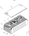
- FIG. 1 is an exploded perspective view of an upper cover of a battery module according to an embodiment of the present invention.
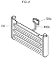
- FIG. 2 is a perspective view of an end plate of the battery module according to an embodiment of the present invention.
- the battery module 100 includes multiple battery cells, an inner cover, a circuit board 110, bus bars 120, end plates 130, side plates 140, and an upper cover 150.
- a battery cell (not shown) is an energy generating device and is comprised of multiple battery cells to be arranged in a first direction x, although not shown.
- the battery cell may include a case having an opening located at its top surface and an electrode assembly accommodated in the case with an electrolyte. The opening of the case may be sealed by a cap assembly.
- electrode terminals having different polarities that is, a positive electrode terminal and a negative electrode terminal, may be provided in the cap assembly defining a top surface of the battery cell.
- An inner cover (not shown) is positioned on upper parts of the multiple battery cells, and multiple bus bars 120 for electrically connecting the multiple battery cells are placed on the inner cover.
- the inner cover may be sized to cover the entire upper parts of the multiple battery cells.
- the inner cover may include a plurality of holes for exposing electrode terminals of the multiple battery cells to the upper parts of the multiple battery cells.
- the inner cover is preferably made of an insulating material.
- the circuit board 110 is coupled to an upper part of the inner cover and includes electronic devices for controlling and monitoring charge/discharge states of the multiple battery cells.
- the circuit board 110 may be coupled to the center of the bus bars 120 on the inner cover so as to be spaced apart from the bus bars 120 arranged in opposite sides of the circuit board 110. That is to say, the circuit board 110 is placed at the center of the upper part of the inner cover in the first direction x, and multiple bus bars 120 for electrically connecting the multiple cells are placed at opposite sides of the circuit board 110 in the first direction x.
- the circuit board 110 may be electrically connected to the bus bars 120.
- the bus bars 120 may be electrically connected to input/output terminals located on a bottom surface of the circuit board 110.
- a circuit board connection part of the bus bars 120 may be connected to the input/output terminals provided on the bottom surface of the circuit board 110.
- the circuit board 110 includes a connector 110a exposed to an exterior side of the battery module 100 to be electrically connected to an external device.
- the connector 110a may be a low-voltage (LV) connector.
- the bus bars 120 connect the battery cells to one another in series or in parallel by connecting electrode terminals of neighboring ones among the battery cells.
- the bus bars 120 are brought into contact with and connected to electrode terminals of upwardly exposed through the inner cover and are supported by the inner cover.
- the bus bars 120 may electrically connect the electrode terminals arranged on the same columns among the multiple battery cells arranged in the first direction x. That is to say, the bus bars 120 may be arranged at opposite sides on the inner cover in the first direction x so as to be spaced apart from each other.
- the bus bars 120 may include a circuit board connection part protruding toward the circuit board 110. The circuit board connection part may be coupled to the circuit board 110 to then be electrically connected thereto.
- the end plates 130 are positioned at facing opposite end cells among the multiple battery cells which are arranged in one direction, respectively. At least one of the end plates 130 positioned at the opposite end cells is made of a metallic material, and the end plate 130 made of the metallic material further includes a connector grounding part 130a and a connection part 130b.
- the connector grounding part 130a is configured to enclose the connector 110a at an entrance part of the connector 110a of the circuit board 110. That is to say, the connector grounding part 130a may be located at the entrance part of the outer end of the connector 110a so as to have a predetermined thickness, conforming to the edge of the entrance part, as shown in FIG. 2 , and may be shaped of a rectangular ring as a whole.
- the connector grounding part 130a may extend to enclose the whole connector 110a or may extend to enclose only top and side surfaces of the connector 110a.
- the connection part 130b is a metallic connection line extending from the main plate of the end plates 130 to the connector grounding part 130a.
- the connection part 130b may be provided so as to be adapted to the curved outer surface shape of the battery module 100 according to the external shape of the battery module 100.
- the connector grounding part 130a and the connection part 130b may be made of the same material as the end plates 130.
- the end plate 130 having the connector grounding part 130a and the connection part 130b may further include an external ground line to be grounded. When the end plate 130 is capable of absorbing ESD energy, the external ground line may not be needed.
- the connector grounding part 130a enclosing the connector 110a of the circuit board 110 is made of a metallic material, the ESD induced to the connector 110a, specifically, to a low-voltage connector, may be allowed to flow out to the end plates 130, which define a metal case, along the connector grounding part 130a exposed to an exterior side of the battery module 100 through the connection part 130b, and to finally flow out to the ground. Accordingly, the ESD or EMC problem arising in the battery module 100 used for an electric car can be solved.
- one end plate 130 of the pair of end plates 130 including the connector grounding part 130a and the connection part 130b, and the other end plate 130b opposite to the one end plate 130a, are made of the same metal, thereby protecting the battery module 100 using the metal case.
- the side plates 140 may be coupled to the pair of end plates 130 so as to cover the short side surfaces of the multiple battery cells. That is to say, the multiple battery cells may be arranged in the first direction x in a space defined by the pair of end plates 130 and the pair of side plates 140.
- the upper cover 150 may be combined with the end plates 130 and the side plates 140 to protect the bus bars 120 and the circuit board 110 from external circumferences.
- the upper cover 150 may be made of an insulating material.
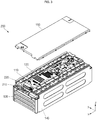
- FIG. 3 is a perspective view of a battery module according to another embodiment of the present invention.
- FIG. 4 is a perspective view of a connector of the battery module according to another embodiment of the present invention.
- FIG. 5 is a front view of the connector shown in FIG. 4 .
- the battery module 200 includes multiple battery cells, an inner cover, a circuit board 110, bus bars 120, end plates 130, side plates 140, and an upper cover 150, like the battery module 100 shown in FIG. 1 .
- the multiple battery cells, the inner cover, the circuit board 110, the bus bars 120, the side plates 140, and the upper cover 150 of the battery module 200 include the same components of the corresponding functional units of the battery module 100, except for the end plates 130 of the battery module 100. That is to say, unlike the end plates 130 of the battery module 100, the end plates 130 of the battery module 200 are not provided with a connector grounding part and a connection part.
- the circuit board 110 of the battery module 200 includes a connector 210, which is different from the connector 110a of the battery module 100 shown in FIG. 1 .
- the connector 210 includes a metallic connector housing 220 located outside the connector 210.
- the connector housing 220 may be fabricated to enclose an inner housing made of an insulating material (not shown).
- the connector housing 220 may be fabricated to enclose multiple connector pins without an inner housing.
- the connector housing 220 may also be fabricated to enclose only a top surface of an insulating housing or only top and side surfaces of the insulating housing. Or else, the connector housing 220 may be located only on an upper portion of an entrance part of the connector 210.
- the connector housing 220 includes a grounding pin connection part 220a electrically connected to a grounding pin led to a grounding line among multiple connecting pins of the connector 210.
- the grounding pin connection part 220a may protrude and extend from an inner surface of the connector housing 220 to then be integrally formed with the grounding pin.
- the grounding pin connection part 220a may be fabricated to enclose the grounding pin such that it extends from the inner surface of the connector housing 220 so as to be electrically connected to the grounding pin.
- FIG. 4 shows that the grounding pin connection part 220a is integrally formed with the grounding pin of the connector 210.
- FIG.5 shows the grounding pin connection part 220a encloses the edge of the grounding pin of the connector 210 to be electrically connected to the grounding pin of the connector 210.
- grounding pin of the connector 210 connected to the grounding pin connection part 220a of the connector housing 220 is connected to a metallic material of the battery module 200 through a pattern of the circuit board 110.
- the metallic material may correspond to the end plates 130 or the side plates 140. Alternatively, the metallic material may correspond to an external grounding line.
- the ESD generated in vicinity of the connector 210 flows out to the grounding pin connection part 220a and the grounding pin through the connector housing 220.
- the ESD having flowed out to the grounding pin will be grounded to the metallic material of the battery module 200 through the pattern of the circuit board or an external grounding line. Therefore, the ESD or EMC problem with the battery module 200 used for an electric car can be solved.
Landscapes
- Chemical & Material Sciences (AREA)
- Chemical Kinetics & Catalysis (AREA)
- Electrochemistry (AREA)
- General Chemical & Material Sciences (AREA)
- Engineering & Computer Science (AREA)
- Manufacturing & Machinery (AREA)
- Microelectronics & Electronic Packaging (AREA)
- Inorganic Chemistry (AREA)
- Battery Mounting, Suspending (AREA)
- Connection Of Batteries Or Terminals (AREA)
- Details Of Connecting Devices For Male And Female Coupling (AREA)
Abstract
Description
- The present invention relates to a battery module.
- In general, battery cells are used as energy sources for mobile devices, electric vehicles, hybrid vehicles, or electric bicycles, and may be used in various types according to the kinds of available external devices.
- Small mobile devices, such as mobile phones, can operate for a predetermined time with the output and capacity of a single battery. However, when a high-power and long-time operation is required like in an electrical vehicle or a hybrid vehicle consuming a large amount of electricity, a large-capacity battery module is constructed by electrically connecting multiple battery cells to increase the output and capacity. The battery module can increase an output voltage or output current according to the number of battery cells included in the battery module. A battery pack may be provided by electrically connecting multiple battery modules.
- Meanwhile, the battery module may be deteriorated due to electromagnetic compatibility (EMC) or electrostatic discharge (ESD) induced to a circuit board, which is a problem to be solved. Specifically, there is a need to deal with ESD energy induced to a low-voltage (LV) connector.
- The present invention provides a battery module configured to deal with ESD induced to a low-voltage connector thereof.
- In accordance with an aspect of the present invention, the above and other objects can be accomplished by providing a battery module including a circuit board stably placed on upper parts of multiple battery cells, a bus bar electrically connecting the multiple battery cells and electrically connected to the circuit board, and a pair of end plates respectively positioned at facing opposite end cells among the multiple battery cells which are arranged in one direction, wherein the circuit board includes a connector located at one end thereof and exposed to an exterior side of the battery module to be electrically connected with an external device, and at least one of the pair of end plates is made of a metallic material and includes a connector grounding part located around the connector, and a connection part connected to the connector grounding part.
- In an example, the connector grounding part and the connection part are made of the same material as the end plates made of a metallic material and are grounded to the end plates.
- In an example, the battery module may further include a pair of side plates coupled to the pair of end plates so as to cover short side surfaces of the multiple battery cells, and an upper cover coupled to the end plates and the side plates to protect the bus bar and the circuit board, wherein the connector is exposed to an exterior side of the upper cover.
- In an example, the connector grounding part may be located at an entrance part of an outer end of the connector so as to have a predetermined thickness, conforming to the edge of the entrance part.
- In an example, the pair of end plates and the pair of side plates may be made of a metallic material and may be grounded.
- In an example, the upper cover may be made of an insulating material.
- In accordance with another aspect of the present invention, the above and other objects can be accomplished by providing a battery module including a circuit board stably placed on upper parts of multiple battery cells, a bus bar electrically connecting the multiple battery cells and electrically connected to the circuit board, a pair of end plates respectively positioned at facing opposite end cells among the multiple battery cells which are arranged in one direction, a pair of side plates coupled to the pair of end plates so as to cover short side surfaces of the multiple battery cells, an upper cover coupled to the end plates and the side plates to protect the bus bar and the circuit board, and a connector located at one end of the circuit board and exposed to an exterior side of the battery module to be electrically connected with an external device, wherein the connector includes a metallic connector housing located outside an entrance part of the connector, and the connector housing includes a grounding pin connector electrically connected to a grounding pin among connecting pins of the connector.
- Here, the grounding pin of the connector connected to a grounding pin connection part of the connector housing may be connected to the metallic material of the battery module through a pattern of the circuit board.
- In accordance with another aspect of the present invention, the above and other objects can be accomplished by providing end plates of a battery module positioned at opposite end cells of multiple battery cells arranged in one direction, the end plates including a main plate made of a metallic material and having an area corresponding to the size of one side surface of the battery module, a connector grounding part made of a metallic material and located around a connector of the battery module, and a connection part made of a metallic material and connecting the connector grounding part and the main plate.
- As described above, the battery module according to an embodiment of the present invention can effuse ESD induced to a low-voltage connector by grounding the ESD using an external metal case through a metallic edge located outside the connector.
- In addition, the battery module according to an embodiment of the present invention can ground ESD induced to a low-voltage connector by connecting an external metal case located outside the connector to a ground line among various internal lines of the connector.
-
-
FIG. 1 is an exploded perspective view of an upper cover of a battery module according to an embodiment of the present invention. -
FIG. 2 is a perspective view of an end plate of the battery module according to an embodiment of the present invention. -
FIG. 3 is a perspective view of a battery module according to another embodiment of the present invention. -
FIG. 4 is a perspective view of a connector of the battery module according to another embodiment of the present invention. -
FIG. 5 is a front view of the connector shown inFIG. 4 . - Hereinafter, a preferred embodiment of the present invention will be described in detail.
- Various embodiments of the present invention may be embodied in many different forms and should not be construed as being limited to the example embodiments set forth herein. Rather, these example embodiments of the disclosure are provided so that this disclosure will be thorough and complete and will convey inventive concepts of the disclosure to those skilled in the art.
- In the accompanying drawings, sizes or thicknesses of various components are exaggerated for brevity and clarity. Like numbers refer to like elements throughout. As used herein, the term "and/or" includes any and all combinations of one or more of the associated listed items. In addition, it will be understood that when an element A is referred to as being "connected to" an element B, the element A can be directly connected to the element B or an intervening element C may be present and the element A and the element B are indirectly connected to each other.
- The terminology used herein is for the purpose of describing particular embodiments only and is not intended to be limiting of the disclosure. As used herein, the singular forms are intended to include the plural forms as well, unless the context clearly indicates otherwise. It will be further understood that the terms "comprise or include" and/or "comprising or including," when used in this specification, specify the presence of stated features, numbers, steps, operations, elements, and/or components, but do not preclude the presence or addition of one or more other features, numbers, steps, operations, elements, components, and/or groups thereof.
- It will be understood that, although the terms first, second, etc. may be used herein to describe various members, elements, regions, layers and/or sections, these members, elements, regions, layers and/or sections should not be limited by these terms. These terms are only used to distinguish one member, element, region, layer and/or section from another. Thus, for example, a first member, a first element, a first region, a first layer and/or a first section discussed below could be termed a second member, a second element, a second region, a second layer and/or a second section without departing from the teachings of the present disclosure.
- Spatially relative terms, such as "beneath," "below," "lower," "above," "upper," and the like, may be used herein for ease of description to describe one element or feature's relationship to another element(s) or feature(s) as illustrated in the figures. It will be understood that the spatially relative terms are intended to encompass different orientations of the device in use or operation in addition to the orientation depicted in the figures. For example, if the device in the figures is turned over, elements described as "below" or "beneath" other elements or features would then be oriented "on" or "above" the other elements or features. Thus, the exemplary term "below" can encompass both an orientation of above and below.
-
FIG. 1 is an exploded perspective view of an upper cover of a battery module according to an embodiment of the present invention.FIG. 2 is a perspective view of an end plate of the battery module according to an embodiment of the present invention. - Referring to
FIGS. 1 and2 , thebattery module 100 according to an embodiment of the present invention includes multiple battery cells, an inner cover, acircuit board 110,bus bars 120,end plates 130,side plates 140, and anupper cover 150. - A battery cell (not shown) is an energy generating device and is comprised of multiple battery cells to be arranged in a first direction x, although not shown. The battery cell may include a case having an opening located at its top surface and an electrode assembly accommodated in the case with an electrolyte. The opening of the case may be sealed by a cap assembly. In addition, electrode terminals having different polarities, that is, a positive electrode terminal and a negative electrode terminal, may be provided in the cap assembly defining a top surface of the battery cell.
- An inner cover (not shown) is positioned on upper parts of the multiple battery cells, and
multiple bus bars 120 for electrically connecting the multiple battery cells are placed on the inner cover. The inner cover may be sized to cover the entire upper parts of the multiple battery cells. In addition, the inner cover may include a plurality of holes for exposing electrode terminals of the multiple battery cells to the upper parts of the multiple battery cells. The inner cover is preferably made of an insulating material. - The
circuit board 110 is coupled to an upper part of the inner cover and includes electronic devices for controlling and monitoring charge/discharge states of the multiple battery cells. Thecircuit board 110 may be coupled to the center of thebus bars 120 on the inner cover so as to be spaced apart from thebus bars 120 arranged in opposite sides of thecircuit board 110. That is to say, thecircuit board 110 is placed at the center of the upper part of the inner cover in the first direction x, andmultiple bus bars 120 for electrically connecting the multiple cells are placed at opposite sides of thecircuit board 110 in the first direction x. In addition, thecircuit board 110 may be electrically connected to thebus bars 120. Thebus bars 120 may be electrically connected to input/output terminals located on a bottom surface of thecircuit board 110. That is to say, a circuit board connection part of the bus bars 120 may be connected to the input/output terminals provided on the bottom surface of thecircuit board 110. In addition, thecircuit board 110 includes aconnector 110a exposed to an exterior side of thebattery module 100 to be electrically connected to an external device. Theconnector 110a may be a low-voltage (LV) connector. - The bus bars 120 connect the battery cells to one another in series or in parallel by connecting electrode terminals of neighboring ones among the battery cells. The bus bars 120 are brought into contact with and connected to electrode terminals of upwardly exposed through the inner cover and are supported by the inner cover. The bus bars 120 may electrically connect the electrode terminals arranged on the same columns among the multiple battery cells arranged in the first direction x. That is to say, the bus bars 120 may be arranged at opposite sides on the inner cover in the first direction x so as to be spaced apart from each other. The bus bars 120 may include a circuit board connection part protruding toward the
circuit board 110. The circuit board connection part may be coupled to thecircuit board 110 to then be electrically connected thereto. - The
end plates 130 are positioned at facing opposite end cells among the multiple battery cells which are arranged in one direction, respectively. At least one of theend plates 130 positioned at the opposite end cells is made of a metallic material, and theend plate 130 made of the metallic material further includes aconnector grounding part 130a and aconnection part 130b. Theconnector grounding part 130a is configured to enclose theconnector 110a at an entrance part of theconnector 110a of thecircuit board 110. That is to say, theconnector grounding part 130a may be located at the entrance part of the outer end of theconnector 110a so as to have a predetermined thickness, conforming to the edge of the entrance part, as shown inFIG. 2 , and may be shaped of a rectangular ring as a whole. Meanwhile, theconnector grounding part 130a may extend to enclose thewhole connector 110a or may extend to enclose only top and side surfaces of theconnector 110a. Theconnection part 130b is a metallic connection line extending from the main plate of theend plates 130 to theconnector grounding part 130a. Theconnection part 130b may be provided so as to be adapted to the curved outer surface shape of thebattery module 100 according to the external shape of thebattery module 100. Theconnector grounding part 130a and theconnection part 130b may be made of the same material as theend plates 130. In addition, theend plate 130 having theconnector grounding part 130a and theconnection part 130b may further include an external ground line to be grounded. When theend plate 130 is capable of absorbing ESD energy, the external ground line may not be needed. - As described above, since the
connector grounding part 130a enclosing theconnector 110a of thecircuit board 110 is made of a metallic material, the ESD induced to theconnector 110a, specifically, to a low-voltage connector, may be allowed to flow out to theend plates 130, which define a metal case, along theconnector grounding part 130a exposed to an exterior side of thebattery module 100 through theconnection part 130b, and to finally flow out to the ground. Accordingly, the ESD or EMC problem arising in thebattery module 100 used for an electric car can be solved. - Meanwhile, one
end plate 130 of the pair ofend plates 130, including theconnector grounding part 130a and theconnection part 130b, and theother end plate 130b opposite to the oneend plate 130a, are made of the same metal, thereby protecting thebattery module 100 using the metal case. - In addition, the
side plates 140 may be coupled to the pair ofend plates 130 so as to cover the short side surfaces of the multiple battery cells. That is to say, the multiple battery cells may be arranged in the first direction x in a space defined by the pair ofend plates 130 and the pair ofside plates 140. - The
upper cover 150 may be combined with theend plates 130 and theside plates 140 to protect the bus bars 120 and thecircuit board 110 from external circumferences. Theupper cover 150 may be made of an insulating material. -
FIG. 3 is a perspective view of a battery module according to another embodiment of the present invention.FIG. 4 is a perspective view of a connector of the battery module according to another embodiment of the present invention.FIG. 5 is a front view of the connector shown inFIG. 4 . - Referring to
FIGS. 3 to 5 , thebattery module 200 according to another embodiment of the present invention includes multiple battery cells, an inner cover, acircuit board 110, bus bars 120,end plates 130,side plates 140, and anupper cover 150, like thebattery module 100 shown inFIG. 1 . - The multiple battery cells, the inner cover, the
circuit board 110, the bus bars 120, theside plates 140, and theupper cover 150 of thebattery module 200 include the same components of the corresponding functional units of thebattery module 100, except for theend plates 130 of thebattery module 100. That is to say, unlike theend plates 130 of thebattery module 100, theend plates 130 of thebattery module 200 are not provided with a connector grounding part and a connection part. - Meanwhile, the
circuit board 110 of thebattery module 200 includes aconnector 210, which is different from theconnector 110a of thebattery module 100 shown inFIG. 1 . Referring toFIGS. 4 and 5 , theconnector 210 includes ametallic connector housing 220 located outside theconnector 210. Theconnector housing 220 may be fabricated to enclose an inner housing made of an insulating material (not shown). Alternatively, theconnector housing 220 may be fabricated to enclose multiple connector pins without an inner housing. Otherwise, theconnector housing 220 may also be fabricated to enclose only a top surface of an insulating housing or only top and side surfaces of the insulating housing. Or else, theconnector housing 220 may be located only on an upper portion of an entrance part of theconnector 210. - The
connector housing 220 includes a groundingpin connection part 220a electrically connected to a grounding pin led to a grounding line among multiple connecting pins of theconnector 210. The groundingpin connection part 220a may protrude and extend from an inner surface of theconnector housing 220 to then be integrally formed with the grounding pin. Alternatively, the groundingpin connection part 220a may be fabricated to enclose the grounding pin such that it extends from the inner surface of theconnector housing 220 so as to be electrically connected to the grounding pin.FIG. 4 shows that the groundingpin connection part 220a is integrally formed with the grounding pin of theconnector 210.FIG.5 shows the groundingpin connection part 220a encloses the edge of the grounding pin of theconnector 210 to be electrically connected to the grounding pin of theconnector 210. - In addition, the grounding pin of the
connector 210 connected to the groundingpin connection part 220a of theconnector housing 220 is connected to a metallic material of thebattery module 200 through a pattern of thecircuit board 110. The metallic material may correspond to theend plates 130 or theside plates 140. Alternatively, the metallic material may correspond to an external grounding line. - As described above, in the
battery module 200 according to another embodiment of the present invention, the ESD generated in vicinity of theconnector 210 flows out to the groundingpin connection part 220a and the grounding pin through theconnector housing 220. The ESD having flowed out to the grounding pin will be grounded to the metallic material of thebattery module 200 through the pattern of the circuit board or an external grounding line. Therefore, the ESD or EMC problem with thebattery module 200 used for an electric car can be solved. - Although the foregoing embodiments have been described to practice the battery module of the present invention, these embodiments are set forth for illustrative purposes and do not serve to limit the invention. Those skilled in the art will readily appreciate that many modifications and variations can be made, without departing from the spirit and scope of the invention as defined in the appended claims, and such modifications and variations are encompassed within the scope and spirit of the present invention.
Claims (9)
- A battery module comprising:a circuit board stably placed on upper parts of multiple battery cells;a bus bar electrically connecting the multiple battery cells and electrically connected to the circuit board; anda pair of end plates respectively positioned at facing opposite end cells among the multiple battery cells which are arranged in one direction,wherein the circuit board comprises a connector located at one end thereof and exposed to an exterior side of the battery module to be electrically connected with an external device, and at least one of the pair of end plates is made of a metallic material and comprises a connector grounding part located around the connector, and a connection part connected to the connector grounding part.
- The battery module of claim 1, wherein the connector grounding part and the connection part are made of the same material as the end plates made of a metallic material and are grounded to the end plates.
- The battery module of claim 1, further comprising:a pair of side plates coupled to the pair of end plates so as to cover short side surfaces of the multiple battery cells; andan upper cover coupled to the end plates and the side plates to protect the bus bar and the circuit board,wherein the connector is exposed to an exterior side of the upper cover.
- The battery module of claim 1, wherein the connector grounding part is located at an entrance of an outer end of the connector so as to have a predetermined thickness, conforming to the edge of the entrance.
- The battery module of claim 3, wherein the pair of end plates and the pair of side plates are made of a metallic material and are grounded.
- The battery module of claim 3, wherein the upper cover is made of an insulating material.
- A battery module comprising:a circuit board stably placed on upper parts of multiple battery cells;a bus bar electrically connecting the multiple battery cells and electrically connected to the circuit board;a pair of end plates respectively positioned at facing opposite end cells among the multiple battery cells which are arranged in one direction;a pair of side plates coupled to the pair of end plates so as to cover short side surfaces of the multiple battery cells;an upper cover coupled to the end plates and the side plates to protect the bus bar and the circuit board; anda connector located at one end of the circuit board and exposed to an exterior side of the battery module to be electrically connected with an external device,wherein the connector comprises a metallic connector housing located outside an entrance of the connector, and the connector housing comprises a grounding pin connector electrically connected to a grounding pin among connecting pins of the connector.
- The battery module of claim 7, wherein the grounding pin of the connector connected to a grounding pin connection part of the connector housing is connected to the metallic material of the battery module through a pattern of the circuit board.
- End plates of a battery module positioned at opposite end cells of multiple battery cells arranged in one direction, the end plates comprising:a main plate made of a metallic material and having an area corresponding to the size of one side surface of the battery module;a connector grounding part made of a metallic material and located around a connector of the battery module; anda connection part made of a metallic material and connecting the connector grounding part and the main plate.
Applications Claiming Priority (2)
| Application Number | Priority Date | Filing Date | Title |
|---|---|---|---|
| KR1020170015582A KR102744299B1 (en) | 2017-02-03 | 2017-02-03 | Battery Module |
| PCT/KR2017/014502 WO2018143556A1 (en) | 2017-02-03 | 2017-12-12 | Battery module |
Publications (3)
| Publication Number | Publication Date |
|---|---|
| EP3579306A1 true EP3579306A1 (en) | 2019-12-11 |
| EP3579306A4 EP3579306A4 (en) | 2020-11-18 |
| EP3579306B1 EP3579306B1 (en) | 2026-01-21 |
Family
ID=63040850
Family Applications (1)
| Application Number | Title | Priority Date | Filing Date |
|---|---|---|---|
| EP17894771.9A Active EP3579306B1 (en) | 2017-02-03 | 2017-12-12 | Battery module |
Country Status (6)
| Country | Link |
|---|---|
| US (1) | US11145941B2 (en) |
| EP (1) | EP3579306B1 (en) |
| JP (2) | JP6848072B2 (en) |
| KR (1) | KR102744299B1 (en) |
| CN (1) | CN110235279B (en) |
| WO (1) | WO2018143556A1 (en) |
Cited By (1)
| Publication number | Priority date | Publication date | Assignee | Title |
|---|---|---|---|---|
| DE102022209545A1 (en) * | 2022-09-13 | 2024-03-14 | Mahle International Gmbh | Drive battery |
Families Citing this family (11)
| Publication number | Priority date | Publication date | Assignee | Title |
|---|---|---|---|---|
| KR102280997B1 (en) | 2017-12-20 | 2021-07-22 | 주식회사 엘지에너지솔루션 | Battery module and battery pack including the same |
| JP7574652B2 (en) * | 2021-01-15 | 2024-10-29 | 株式会社オートネットワーク技術研究所 | External Busbar and Wiring Modules |
| WO2022163477A1 (en) * | 2021-01-29 | 2022-08-04 | 三洋電機株式会社 | Power supply device and method for producing same |
| CN117121642A (en) | 2021-03-31 | 2023-11-24 | 松下知识产权经营株式会社 | circuit board |
| KR20220161057A (en) | 2021-05-28 | 2022-12-06 | 주식회사 엘지에너지솔루션 | Battery module and battery pack including the same |
| CN113364904B (en) * | 2021-06-04 | 2024-04-26 | 维沃移动通信有限公司 | Electronic equipment |
| US12609410B2 (en) | 2021-09-23 | 2026-04-21 | Lg Energy Solution, Ltd. | High heat-resistant connector, and battery module, battery pack, and vehicle including the same |
| KR20230063235A (en) * | 2021-11-01 | 2023-05-09 | 주식회사 엘지에너지솔루션 | Battery module with improved flame-retardant connector |
| KR20230133538A (en) | 2022-03-11 | 2023-09-19 | 주식회사 엘지에너지솔루션 | Connector for Battery Pack with High Heat Resistance to Prevent Thermal Propagation |
| KR20230145830A (en) * | 2022-04-11 | 2023-10-18 | 주식회사 엘지에너지솔루션 | Battery pack connector for connecting to external devices |
| CN117529856A (en) | 2022-05-26 | 2024-02-06 | 株式会社Lg新能源 | High heat-resistant connector for battery pack and manufacturing method thereof |
Family Cites Families (19)
| Publication number | Priority date | Publication date | Assignee | Title |
|---|---|---|---|---|
| JPH03112080A (en) * | 1989-09-27 | 1991-05-13 | Canon Inc | Connection structure of electronic equipment |
| KR100863729B1 (en) * | 2006-09-18 | 2008-10-16 | 주식회사 엘지화학 | Battery module interface |
| KR101449753B1 (en) * | 2008-05-08 | 2014-10-13 | 타이코에이엠피(유) | An electrical connection device of a battery cell module and a battery cell module including the same |
| KR100995429B1 (en) * | 2008-10-13 | 2010-11-18 | 삼성에스디아이 주식회사 | Battery pack |
| KR101329888B1 (en) | 2009-02-05 | 2013-11-15 | 삼성에스디아이 주식회사 | Protection circuit for battery pack and battery pack with the same |
| JP2010287514A (en) * | 2009-06-12 | 2010-12-24 | Sanyo Electric Co Ltd | Power supply device, and vehicle equipped with this |
| KR101297176B1 (en) * | 2010-06-03 | 2013-08-21 | 주식회사 엘지화학 | Battery Module Having Novel Structure |
| KR101146492B1 (en) * | 2010-07-01 | 2012-05-21 | 에스비리모티브 주식회사 | Battery Pack |
| KR101234241B1 (en) * | 2011-02-17 | 2013-02-18 | 삼성에스디아이 주식회사 | Rechargeable Battery pack |
| WO2013099499A1 (en) * | 2011-12-28 | 2013-07-04 | 三洋電機株式会社 | Power supply apparatus, circuit board, vehicle provided with power supply apparatus, and electric storage apparatus |
| WO2013098982A1 (en) * | 2011-12-28 | 2013-07-04 | 日立ビークルエナジー株式会社 | Battery module, battery block, and battery pack |
| US9362536B2 (en) * | 2012-04-25 | 2016-06-07 | Robert Bosch Gmbh | Optimized module restraint system |
| KR20140130357A (en) * | 2013-04-30 | 2014-11-10 | 타이코에이엠피(유) | Secondary battery pack |
| KR101638113B1 (en) | 2013-05-06 | 2016-07-08 | 주식회사 엘지화학 | Battery pack and protective circuit module applied for the same |
| TWI536690B (en) * | 2013-11-13 | 2016-06-01 | 緯創資通股份有限公司 | Noise suppress assembly and electronic device having the same |
| JP6183383B2 (en) | 2015-01-13 | 2017-08-23 | トヨタ自動車株式会社 | vehicle |
| JP6202024B2 (en) * | 2015-03-10 | 2017-09-27 | トヨタ自動車株式会社 | Battery module |
| KR102009443B1 (en) * | 2015-06-19 | 2019-08-12 | 주식회사 엘지화학 | Cartridge And Battery Module Comprising The Same |
| KR102085344B1 (en) | 2016-10-24 | 2020-04-23 | 주식회사 엘지화학 | Battery pack for a vehicle and Vehicle including the same |
-
2017
- 2017-02-03 KR KR1020170015582A patent/KR102744299B1/en active Active
- 2017-12-12 JP JP2019538625A patent/JP6848072B2/en active Active
- 2017-12-12 EP EP17894771.9A patent/EP3579306B1/en active Active
- 2017-12-12 WO PCT/KR2017/014502 patent/WO2018143556A1/en not_active Ceased
- 2017-12-12 CN CN201780085039.XA patent/CN110235279B/en active Active
-
2019
- 2019-08-01 US US16/529,566 patent/US11145941B2/en active Active
-
2021
- 2021-03-03 JP JP2021033471A patent/JP6978619B2/en active Active
Cited By (1)
| Publication number | Priority date | Publication date | Assignee | Title |
|---|---|---|---|---|
| DE102022209545A1 (en) * | 2022-09-13 | 2024-03-14 | Mahle International Gmbh | Drive battery |
Also Published As
| Publication number | Publication date |
|---|---|
| JP2021082608A (en) | 2021-05-27 |
| US11145941B2 (en) | 2021-10-12 |
| KR102744299B1 (en) | 2024-12-18 |
| WO2018143556A1 (en) | 2018-08-09 |
| EP3579306B1 (en) | 2026-01-21 |
| US20190355959A1 (en) | 2019-11-21 |
| CN110235279B (en) | 2022-06-03 |
| KR20180090572A (en) | 2018-08-13 |
| CN110235279A (en) | 2019-09-13 |
| EP3579306A4 (en) | 2020-11-18 |
| JP6978619B2 (en) | 2021-12-08 |
| JP6848072B2 (en) | 2021-03-24 |
| JP2020506506A (en) | 2020-02-27 |
Similar Documents
| Publication | Publication Date | Title |
|---|---|---|
| US11145941B2 (en) | Battery module | |
| CN108780860B (en) | Battery pack for vehicle and vehicle including battery pack | |
| EP2463938A1 (en) | Battery module and assembled battery | |
| KR102283962B1 (en) | Battery module | |
| KR20190106161A (en) | Battery Pack using battery module with short-circuit protection structure | |
| KR20170050092A (en) | Fuse assembly structure of secondary battery pack | |
| US10069120B2 (en) | Battery module | |
| EP3316386B1 (en) | Connector part for a printed circuit board and a battery system comprising the printed circuit board and the connector part | |
| US9997809B2 (en) | Battery module | |
| CN105990601B (en) | Battery | |
| EP3608993B1 (en) | Battery module comprising connecting board | |
| US8679657B2 (en) | Battery pack | |
| US12463291B2 (en) | Pouch-type battery pack having folding structure and manufacturing method there-of | |
| CN104835927A (en) | Battery pack | |
| KR101483130B1 (en) | Battery Pack | |
| KR102849125B1 (en) | Battery Pack | |
| KR20250083773A (en) | Battery module and battery pack including the same | |
| US9312529B2 (en) | Secondary battery and secondary battery assembly | |
| US9166256B2 (en) | Rechargeable battery | |
| KR102459620B1 (en) | Battery pack | |
| KR20190096729A (en) | Battery pack |
Legal Events
| Date | Code | Title | Description |
|---|---|---|---|
| STAA | Information on the status of an ep patent application or granted ep patent |
Free format text: STATUS: THE INTERNATIONAL PUBLICATION HAS BEEN MADE |
|
| PUAI | Public reference made under article 153(3) epc to a published international application that has entered the european phase |
Free format text: ORIGINAL CODE: 0009012 |
|
| STAA | Information on the status of an ep patent application or granted ep patent |
Free format text: STATUS: REQUEST FOR EXAMINATION WAS MADE |
|
| 17P | Request for examination filed |
Effective date: 20190711 |
|
| AK | Designated contracting states |
Kind code of ref document: A1 Designated state(s): AL AT BE BG CH CY CZ DE DK EE ES FI FR GB GR HR HU IE IS IT LI LT LU LV MC MK MT NL NO PL PT RO RS SE SI SK SM TR |
|
| AX | Request for extension of the european patent |
Extension state: BA ME |
|
| DAV | Request for validation of the european patent (deleted) | ||
| DAX | Request for extension of the european patent (deleted) | ||
| A4 | Supplementary search report drawn up and despatched |
Effective date: 20201015 |
|
| RIC1 | Information provided on ipc code assigned before grant |
Ipc: H01R 12/51 20110101ALI20201009BHEP Ipc: H05K 1/02 20060101ALI20201009BHEP Ipc: H01M 10/04 20060101ALI20201009BHEP Ipc: H01M 10/42 20060101ALI20201009BHEP Ipc: H01M 2/10 20060101ALI20201009BHEP Ipc: H01R 13/652 20060101ALI20201009BHEP Ipc: H01M 2/20 20060101ALI20201009BHEP Ipc: H01M 2/34 20060101AFI20201009BHEP |
|
| STAA | Information on the status of an ep patent application or granted ep patent |
Free format text: STATUS: EXAMINATION IS IN PROGRESS |
|
| 17Q | First examination report despatched |
Effective date: 20230104 |
|
| REG | Reference to a national code |
Ref country code: DE Ref legal event code: R079 Free format text: PREVIOUS MAIN CLASS: H01M0002340000 Ipc: H01M0010420000 Ref country code: DE Ref legal event code: R079 Ref document number: 602017093663 Country of ref document: DE Free format text: PREVIOUS MAIN CLASS: H01M0002340000 Ipc: H01M0010420000 |
|
| GRAP | Despatch of communication of intention to grant a patent |
Free format text: ORIGINAL CODE: EPIDOSNIGR1 |
|
| STAA | Information on the status of an ep patent application or granted ep patent |
Free format text: STATUS: GRANT OF PATENT IS INTENDED |
|
| RIC1 | Information provided on ipc code assigned before grant |
Ipc: H01M 10/42 20060101AFI20250822BHEP Ipc: H05K 1/02 20060101ALI20250822BHEP Ipc: H01R 12/51 20110101ALI20250822BHEP Ipc: H01M 10/04 20060101ALI20250822BHEP Ipc: H01R 13/652 20060101ALI20250822BHEP Ipc: H01M 50/209 20210101ALI20250822BHEP Ipc: H01M 50/224 20210101ALI20250822BHEP Ipc: H01M 50/271 20210101ALI20250822BHEP Ipc: H01M 50/296 20210101ALI20250822BHEP Ipc: H01M 50/588 20210101ALI20250822BHEP Ipc: H01M 50/591 20210101ALI20250822BHEP Ipc: H01M 50/519 20210101ALI20250822BHEP Ipc: H01M 50/50 20210101ALI20250822BHEP |
|
| INTG | Intention to grant announced |
Effective date: 20250905 |
|
| GRAS | Grant fee paid |
Free format text: ORIGINAL CODE: EPIDOSNIGR3 |
|
| GRAA | (expected) grant |
Free format text: ORIGINAL CODE: 0009210 |
|
| STAA | Information on the status of an ep patent application or granted ep patent |
Free format text: STATUS: THE PATENT HAS BEEN GRANTED |
|
| AK | Designated contracting states |
Kind code of ref document: B1 Designated state(s): AL AT BE BG CH CY CZ DE DK EE ES FI FR GB GR HR HU IE IS IT LI LT LU LV MC MK MT NL NO PL PT RO RS SE SI SK SM TR |
|
| REG | Reference to a national code |
Ref country code: CH Ref legal event code: F10 Free format text: ST27 STATUS EVENT CODE: U-0-0-F10-F00 (AS PROVIDED BY THE NATIONAL OFFICE) Effective date: 20260121 |
|
| REG | Reference to a national code |
Ref country code: IE Ref legal event code: FG4D |
|
| REG | Reference to a national code |
Ref country code: DE Ref legal event code: R096 Ref document number: 602017093663 Country of ref document: DE |