EP3579297A1 - Cell pack - Google Patents
Cell pack Download PDFInfo
- Publication number
- EP3579297A1 EP3579297A1 EP18747214.7A EP18747214A EP3579297A1 EP 3579297 A1 EP3579297 A1 EP 3579297A1 EP 18747214 A EP18747214 A EP 18747214A EP 3579297 A1 EP3579297 A1 EP 3579297A1
- Authority
- EP
- European Patent Office
- Prior art keywords
- housing
- battery
- secondary battery
- electrode terminal
- wide
- Prior art date
- Legal status (The legal status is an assumption and is not a legal conclusion. Google has not performed a legal analysis and makes no representation as to the accuracy of the status listed.)
- Withdrawn
Links
Images



Classifications
-
- H—ELECTRICITY
- H01—ELECTRIC ELEMENTS
- H01M—PROCESSES OR MEANS, e.g. BATTERIES, FOR THE DIRECT CONVERSION OF CHEMICAL ENERGY INTO ELECTRICAL ENERGY
- H01M10/00—Secondary cells; Manufacture thereof
- H01M10/60—Heating or cooling; Temperature control
- H01M10/65—Means for temperature control structurally associated with the cells
- H01M10/655—Solid structures for heat exchange or heat conduction
- H01M10/6554—Rods or plates
-
- H—ELECTRICITY
- H01—ELECTRIC ELEMENTS
- H01M—PROCESSES OR MEANS, e.g. BATTERIES, FOR THE DIRECT CONVERSION OF CHEMICAL ENERGY INTO ELECTRICAL ENERGY
- H01M10/00—Secondary cells; Manufacture thereof
- H01M10/60—Heating or cooling; Temperature control
- H01M10/61—Types of temperature control
- H01M10/613—Cooling or keeping cold
-
- H—ELECTRICITY
- H01—ELECTRIC ELEMENTS
- H01M—PROCESSES OR MEANS, e.g. BATTERIES, FOR THE DIRECT CONVERSION OF CHEMICAL ENERGY INTO ELECTRICAL ENERGY
- H01M10/00—Secondary cells; Manufacture thereof
- H01M10/60—Heating or cooling; Temperature control
- H01M10/64—Heating or cooling; Temperature control characterised by the shape of the cells
- H01M10/647—Prismatic or flat cells, e.g. pouch cells
-
- H—ELECTRICITY
- H01—ELECTRIC ELEMENTS
- H01M—PROCESSES OR MEANS, e.g. BATTERIES, FOR THE DIRECT CONVERSION OF CHEMICAL ENERGY INTO ELECTRICAL ENERGY
- H01M10/00—Secondary cells; Manufacture thereof
- H01M10/60—Heating or cooling; Temperature control
- H01M10/65—Means for temperature control structurally associated with the cells
- H01M10/653—Means for temperature control structurally associated with the cells characterised by electrically insulating or thermally conductive materials
-
- H—ELECTRICITY
- H01—ELECTRIC ELEMENTS
- H01M—PROCESSES OR MEANS, e.g. BATTERIES, FOR THE DIRECT CONVERSION OF CHEMICAL ENERGY INTO ELECTRICAL ENERGY
- H01M10/00—Secondary cells; Manufacture thereof
- H01M10/60—Heating or cooling; Temperature control
- H01M10/65—Means for temperature control structurally associated with the cells
- H01M10/655—Solid structures for heat exchange or heat conduction
- H01M10/6551—Surfaces specially adapted for heat dissipation or radiation, e.g. fins or coatings
-
- H—ELECTRICITY
- H01—ELECTRIC ELEMENTS
- H01M—PROCESSES OR MEANS, e.g. BATTERIES, FOR THE DIRECT CONVERSION OF CHEMICAL ENERGY INTO ELECTRICAL ENERGY
- H01M10/00—Secondary cells; Manufacture thereof
- H01M10/60—Heating or cooling; Temperature control
- H01M10/65—Means for temperature control structurally associated with the cells
- H01M10/655—Solid structures for heat exchange or heat conduction
- H01M10/6556—Solid parts with flow channel passages or pipes for heat exchange
-
- H—ELECTRICITY
- H01—ELECTRIC ELEMENTS
- H01M—PROCESSES OR MEANS, e.g. BATTERIES, FOR THE DIRECT CONVERSION OF CHEMICAL ENERGY INTO ELECTRICAL ENERGY
- H01M50/00—Constructional details or processes of manufacture of the non-active parts of electrochemical cells other than fuel cells, e.g. hybrid cells
- H01M50/10—Primary casings; Jackets or wrappings
- H01M50/102—Primary casings; Jackets or wrappings characterised by their shape or physical structure
- H01M50/103—Primary casings; Jackets or wrappings characterised by their shape or physical structure prismatic or rectangular
-
- H—ELECTRICITY
- H01—ELECTRIC ELEMENTS
- H01M—PROCESSES OR MEANS, e.g. BATTERIES, FOR THE DIRECT CONVERSION OF CHEMICAL ENERGY INTO ELECTRICAL ENERGY
- H01M50/00—Constructional details or processes of manufacture of the non-active parts of electrochemical cells other than fuel cells, e.g. hybrid cells
- H01M50/20—Mountings; Secondary casings or frames; Racks, modules or packs; Suspension devices; Shock absorbers; Transport or carrying devices; Holders
- H01M50/204—Racks, modules or packs for multiple batteries or multiple cells
- H01M50/207—Racks, modules or packs for multiple batteries or multiple cells characterised by their shape
- H01M50/209—Racks, modules or packs for multiple batteries or multiple cells characterised by their shape adapted for prismatic or rectangular cells
-
- H—ELECTRICITY
- H01—ELECTRIC ELEMENTS
- H01M—PROCESSES OR MEANS, e.g. BATTERIES, FOR THE DIRECT CONVERSION OF CHEMICAL ENERGY INTO ELECTRICAL ENERGY
- H01M50/00—Constructional details or processes of manufacture of the non-active parts of electrochemical cells other than fuel cells, e.g. hybrid cells
- H01M50/20—Mountings; Secondary casings or frames; Racks, modules or packs; Suspension devices; Shock absorbers; Transport or carrying devices; Holders
- H01M50/296—Mountings; Secondary casings or frames; Racks, modules or packs; Suspension devices; Shock absorbers; Transport or carrying devices; Holders characterised by terminals of battery packs
-
- H—ELECTRICITY
- H01—ELECTRIC ELEMENTS
- H01M—PROCESSES OR MEANS, e.g. BATTERIES, FOR THE DIRECT CONVERSION OF CHEMICAL ENERGY INTO ELECTRICAL ENERGY
- H01M50/00—Constructional details or processes of manufacture of the non-active parts of electrochemical cells other than fuel cells, e.g. hybrid cells
- H01M50/50—Current conducting connections for cells or batteries
- H01M50/543—Terminals
- H01M50/547—Terminals characterised by the disposition of the terminals on the cells
- H01M50/55—Terminals characterised by the disposition of the terminals on the cells on the same side of the cell
-
- H—ELECTRICITY
- H01—ELECTRIC ELEMENTS
- H01M—PROCESSES OR MEANS, e.g. BATTERIES, FOR THE DIRECT CONVERSION OF CHEMICAL ENERGY INTO ELECTRICAL ENERGY
- H01M50/00—Constructional details or processes of manufacture of the non-active parts of electrochemical cells other than fuel cells, e.g. hybrid cells
- H01M50/50—Current conducting connections for cells or batteries
- H01M50/543—Terminals
- H01M50/552—Terminals characterised by their shape
- H01M50/553—Terminals adapted for prismatic, pouch or rectangular cells
-
- H—ELECTRICITY
- H01—ELECTRIC ELEMENTS
- H01M—PROCESSES OR MEANS, e.g. BATTERIES, FOR THE DIRECT CONVERSION OF CHEMICAL ENERGY INTO ELECTRICAL ENERGY
- H01M10/00—Secondary cells; Manufacture thereof
- H01M10/05—Accumulators with non-aqueous electrolyte
- H01M10/052—Li-accumulators
- H01M10/0525—Rocking-chair batteries, i.e. batteries with lithium insertion or intercalation in both electrodes; Lithium-ion batteries
-
- H—ELECTRICITY
- H01—ELECTRIC ELEMENTS
- H01M—PROCESSES OR MEANS, e.g. BATTERIES, FOR THE DIRECT CONVERSION OF CHEMICAL ENERGY INTO ELECTRICAL ENERGY
- H01M2220/00—Batteries for particular applications
- H01M2220/20—Batteries in motive systems, e.g. vehicle, ship, plane
-
- H—ELECTRICITY
- H01—ELECTRIC ELEMENTS
- H01M—PROCESSES OR MEANS, e.g. BATTERIES, FOR THE DIRECT CONVERSION OF CHEMICAL ENERGY INTO ELECTRICAL ENERGY
- H01M50/00—Constructional details or processes of manufacture of the non-active parts of electrochemical cells other than fuel cells, e.g. hybrid cells
- H01M50/50—Current conducting connections for cells or batteries
- H01M50/502—Interconnectors for connecting terminals of adjacent batteries; Interconnectors for connecting cells outside a battery casing
- H01M50/503—Interconnectors for connecting terminals of adjacent batteries; Interconnectors for connecting cells outside a battery casing characterised by the shape of the interconnectors
-
- H—ELECTRICITY
- H01—ELECTRIC ELEMENTS
- H01M—PROCESSES OR MEANS, e.g. BATTERIES, FOR THE DIRECT CONVERSION OF CHEMICAL ENERGY INTO ELECTRICAL ENERGY
- H01M50/00—Constructional details or processes of manufacture of the non-active parts of electrochemical cells other than fuel cells, e.g. hybrid cells
- H01M50/50—Current conducting connections for cells or batteries
- H01M50/502—Interconnectors for connecting terminals of adjacent batteries; Interconnectors for connecting cells outside a battery casing
- H01M50/509—Interconnectors for connecting terminals of adjacent batteries; Interconnectors for connecting cells outside a battery casing characterised by the type of connection, e.g. mixed connections
- H01M50/51—Connection only in series
-
- Y—GENERAL TAGGING OF NEW TECHNOLOGICAL DEVELOPMENTS; GENERAL TAGGING OF CROSS-SECTIONAL TECHNOLOGIES SPANNING OVER SEVERAL SECTIONS OF THE IPC; TECHNICAL SUBJECTS COVERED BY FORMER USPC CROSS-REFERENCE ART COLLECTIONS [XRACs] AND DIGESTS
- Y02—TECHNOLOGIES OR APPLICATIONS FOR MITIGATION OR ADAPTATION AGAINST CLIMATE CHANGE
- Y02E—REDUCTION OF GREENHOUSE GAS [GHG] EMISSIONS, RELATED TO ENERGY GENERATION, TRANSMISSION OR DISTRIBUTION
- Y02E60/00—Enabling technologies; Technologies with a potential or indirect contribution to GHG emissions mitigation
- Y02E60/10—Energy storage using batteries
Definitions
- the present invention relates to a cell pack.
- a cell pack including a battery group including a plurality of lithium ion secondary batteries is used as a power supply of an electric vehicle, a hybrid electric vehicle, or an electric device.
- a structure having a cooling device in which heat distribution pipes having flow paths of a refrigerant are disposed on a bottom surface of a battery group housed in a housing with a heat transfer sheet interposed therebetween and a heat radiation member having heat radiation fins is disposed to be closely adhered to the heat dispersion pipe has been known (see, for example, PTL 1).
- a cell pack includes a battery group which includes a plurality of secondary battery cells each having a pair of wide-width surfaces, a pair of narrow-width surfaces, a bottom surface, and an external terminal formed to face the bottom surface; a housing which has one side surface, another side surface adjacent to the one side surface, and a facing side surface facing the other side surface and houses the battery group; and a pack external terminal which is disposed adjacent to the facing side surface of the housing and is connected to the external terminal of the battery group, wherein the secondary battery cells of the battery group are stacked so that the wide-width surfaces face each other, the battery group is housed in the housing in a state in which a wide-width surface of a secondary battery cell of a lowermost layer and the one side surface of the housing are coupled to each other so as to be capable of conducting heat therebetween and the bottom surfaces of the secondary battery cells and the other side surface of the housing are coupled to each other so as to be capable of conducting heat therebetween, and a height of the facing side
- a structure is simplified, such that workability of assembly can be improved.
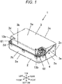
- FIG. 1 is a perspective view showing an appearance of a cell pack according to an embodiment of the invention
- FIG. 2 is a perspective view of the cell pack shown in FIG. 1 in a state in which an upper cover of the cell pack is opened.
- a cell pack 1 has a housing including a case body 2 and an upper cover 3.
- the case body 2 and the upper cover 3 are formed of a resin or a metal.
- the case body 2 has a bottom surface 2a, a front side surface 2b, a rear side surface 2c, a left side surface 2d, and a right side surface 2e, and is formed in a box shape of which an inner portion is a space.
- a left and right direction, a front and rear direction, and a top and bottom direction are defined as shown.
- the front side surface 2b of the case body 2 is formed to be lower than the rear side surface 2c.
- the left side surface 2d and the right side surface 2e of the case body 2 have flat portions of which upper end surfaces have the same height as that of the front side surface 2b and inclined portions extending from the flat portions to an upper end surface of the front side surface 2b.
- the upper cover 3 has an upper surface 3a, a front side surface 3b, a rear side surface 3c, a left side surface 3d, and a right side surface 3e.
- the front side surface 3b of the upper cover 3 is formed to be higher than the rear side surface 3c.
- the left side surface 3d and the right side surface 3e of the upper cover 3 have flat portions of which lower end surfaces have the same height as that of the front side surface 3b and inclined portions extending from the flat portions to a lower end surface of the rear side surface 3c.
- the case body 2 and the upper cover 3 are formed so that lengths of the flat portions and lengths and inclination angles of the inclined portions of each of them are substantially the same as each other, and are combined with each other so that a housing 4 has a rectangular parallelepiped shape.
- Recesses 13a and 13b are formed in left and right end portion sides of a front surface side of the upper cover 3, respectively. Openings are formed in bottom portions of the recesses 13a and 13b, respectively, a pack negative electrode terminal 61 protrudes outward from the opening of the recess 13a and a pack positive electrode terminal 62 protrudes outward from the opening of the recess 13b.
- a signal connector 4 is mounted on a bottom surface of the recess 13b.
- the pack negative electrode terminal 61 and the pack positive electrode terminal 62 are disposed at a position higher than the front side surface 2b of the case body 2.
- each of the pack negative electrode terminal 61 and the pack positive electrode terminal 62 is disposed at a position lower than an upper surface of a battery module 10 to be described below.
- a wiring member inserted into an opening provided in a side surface of the recess 13b is connected to the signal connector 4 of the case body 2.
- the battery module 10 and a contactor module 40 are housed in the case body 2.
- the battery module 10 is disposed at a position corresponding to the inclined portions of the left side surface 2d and the right side surface 2e of the case body 2, that is, a rear side of the case body 2.
- the contactor module 40 is disposed at a position corresponding to the flat portions of the left side surface 2d and the right side surface 2e of the case body 2, that is, a front side of the case body 2.
- the battery module 10 will be described as a battery module having prismatic lithium ion secondary battery cells.
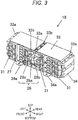
- FIG. 3 is a perspective view of a battery module shown in FIG. 2
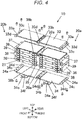
- FIG. 4 is an exploded perspective view of battery groups shown in FIG. 3
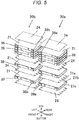
- FIG. 5 is an exploded perspective view of the battery groups shown in FIG. 4 .
- the battery module 10 includes two battery groups 20a and 20b, a bus bar case 27 disposed in front of the battery groups 20a and 20b, a pair of upper and lower end plates 33 and 34, a pair of left and right side plates 36, and a center plate 35.
- the end plates 33 and 34, the pair of side plates 36, and the center plate 35 are formed of a metal such as aluminum.
- the respective battery groups 20a and 20b include a plurality of secondary battery cells 21 (six secondary battery cells in the embodiment), and are arranged in parallel on the left and right.
- the battery group 20a and the battery group 20b have the same structure.
- the secondary battery cell 21 has a thin rectangular parallelepiped shape, and has a battery container including a battery can having a bottom surface 21a, a pair of wide-width surfaces 21b and a pair of narrow-width surfaces 21c and a battery lid provided to cover an opening (not shown) formed to face the bottom surface 21a of the battery can and sealing the battery can.
- the respective secondary battery cells 21 are stacked in the top and bottom direction with the wide-width surfaces 21b thereof facing each other.
- Insulating plates 24 are disposed between secondary battery cells 21 vertically adjacent to each other, above a secondary battery cell 21 of the uppermost layer, and below a secondary battery cell 21 of the lowermost layer.
- the insulating plate 24 is formed of, for example, polybutylene terephthalate (PBT).
- a positive electrode terminal 38 and a negative electrode terminal 39 are mounted on the battery lid of the secondary battery cell 21 in a state in which they are insulated from the battery lid 23.
- a positive electrode connection portion and a negative electrode connection portion of a power generation element housed in the battery container are connected to the positive electrode terminal 38 and the negative electrode terminal 39, respectively.
- the respective secondary battery cells 21 are alternately stacked with the other secondary battery cells 21 vertically adjacent thereto with front and back surfaces of the pair of wide-width surfaces 21b inverted so that a positive electrode terminal 38 of one secondary battery cell 21 and a negative electrode terminal 39 of the other secondary battery cell 21 face each other.
- the positive electrode terminal 38 of one secondary battery cell 21 and the negative electrode terminal 39 of the other secondary battery cell 21 vertically adjacent to each other are connected to each other by an inter-cell bus bar 31 (see FIG. 3 ).
- the positive electrode terminal 38 and the negative electrode terminal 39, and the inter-cell bus bar 31 are joined to each other by, for example, welding.
- the plurality of secondary battery cells 21 constituting each of the battery groups 20a and 20b are electrically connected to each other in series.
- a positive electrode terminal 38a of the uppermost layer of the battery group 20a is disposed in the vicinity of the left battery group 20b, and becomes the highest potential portion of the battery group 20a.
- a negative electrode terminal 39a of the lowermost layer of the battery group 20a is disposed in the vicinity of the left battery group 20b, and becomes the lowest potential portion of the battery group 20a.
- a positive electrode terminal 38b of the lowermost layer of the battery group 20b is disposed in the vicinity of the right battery group 20a, and becomes the highest potential portion of the battery group 20b.
- the negative electrode terminal 39a of the lowest potential of the battery group 20a and the positive electrode terminal 38b of the highest potential of the battery group 20b are connected to each other by an inter-group bus bar (not shown) .
- a negative electrode terminal 39b of the uppermost layer of the left battery group 20b is disposed in the vicinity of the battery group 20a, and is the lowest potential portion of the battery group 20b.
- the battery group 20a and the battery group 20b are electrically connected to each other in series
- the positive electrode terminal 38a of the uppermost layer of the electrode group 20a is the highest potential portion of the battery group 20a and the battery group 20b
- the negative electrode terminal 39b of the uppermost layer of the battery group 20b becomes the lowest potential portion of the battery group 20a and the battery group 20b.
- the battery group 20a and the battery group 20b are disposed on the left and the right of the center plate 35, respectively.
- the side plates 36 are disposed on a right side surface of the battery group 20a and a left side surface of the battery group 20b, respectively.
- Pins 37 are provided on upper and lower surfaces of each side plate 36.
- the end plates 33 and 34 are substantially flat members having sizes enough to cover the entire upper surface or the entire lower surface of the battery groups 20a and 20b, the center plate 35, and the pair of side plates 36, respectively. As shown in FIG. 4 , the end plates 33 and 34 are provided with mounting portions 33a and 34a that fix the pair of side plates 36 and mounting portions 33b and 34b that fix the center plate 35, respectively.
- the mounting portions 33a and 34a are provided with positioning holes 33c and 34c and through-holes 33d and 34d, respectively.
- the mounting portions 33b and 34b are provided with through-holes 33d and 34d, respectively.
- a fixing piece 34e having a mounting hole 34f is formed in the end plate 34.
- the battery module 10 is configured in a state in which the secondary battery cells 21 constituting the battery groups 20a and 20b are pushed from left and right directions to the center plate 35 by the pair of side plates 36 and are pressed from top and bottom directions through the insulating plates 24 by the pair of end plates 34 and 36.
- a method of configuring the battery module as described above will be described.
- the center plate 35, the battery groups 20a and 20b, and the pair of side plates 36 are disposed on the end plate 34, and the battery groups 20a and 20b are pressed from the left and right directions toward the center plate 35 side through the side plates 36.
- a heat transfer sheet may be interposed between each of the battery groups 20a and 20b and the center plate 35.
- positions of the pins 37 of the side plates 36 in the left and right directions are made to coincide with the respective positioning holes 34c of the end plate 34.
- the pins 37 of the respective side plates 36 are inserted into the positioning holes 34c of the end plate 34.
- fastening members such as bolts are inserted into the through-holes 34d of the end plate 34 to fix the center plate 35 and the pair of side plates 36 to the end plate 34.
- the positioning holes 33c of the end plate 33 are aligned with the pins 37 of the respective side plates 36, the pins 37 of the respective side plates 36 are inserted into the positioning holes 33c of the end plate 33, and fastening members such as bolts are inserted into the through-holes 33d of the end plate 33 to fix the end plate 33 to the center plate 35 and the pair of side plates 36.
- the battery module 10 in which the secondary battery cells 21 constituting the battery groups 20a and 20b are secured in the left and right directions and the top and bottom directions is obtained.
- each of the battery groups 20a and 20b is secured by the pair of end plates 33 and 34, and the two battery groups 20a and 20b are secured by the pair of end plates 33 and 34. For this reason, cost reduction can be achieved, and an assembly work is facilitated.
- the battery groups 20a and 20b and the end plates 33 and 34 are aligned with each other only at two places on a left end side and a right end side of the battery groups 20a and 20b, such that positioning accuracy and work efficiency improvement can be achieved.
- the end plates 33 and 34 are not only fixed to the side plates 36 on the left end side and the right end side of the battery groups 20a and 20b, but are also fixed to the center plate 35 in a central portion. For this reason, warpage of the end plates 33 and 34 can be suppressed. Therefore, thicknesses of the end plates 33 and 34 are reduced, such that cost reduction can be achieved.
- the bus bar case 27 is disposed on a front surface side of the battery groups 20a and 20b.
- the bus bar case 27 covers front surfaces of the battery groups 20a and 20b and the inter-cell bus bar 31 in a state in which the front surfaces of the battery groups 20a and 20b and the inter-cell bus bar 31 are partially exposed.
- a terminal disposition portion 28 is provided on a front surface of the bus bar case 27.
- a separating wall 28a protruding upward is formed at the center of the terminal disposition portion 28 in the left and right direction.
- An upper surface of the terminal disposition portion 28 is separated into a positive electrode terminal disposition surface 28b and a negative electrode terminal disposition surface 28c by the separating wall 28a.
- FIG. 6 is a perspective view of a contactor module shown in FIG. 2
- FIG. 7 is a perspective view of the contactor module shown in FIG. 6 when viewed from a rear side.
- the contactor module 40 includes a holder 41 and electrical components such as a board 42, a relay (contactor) 43, a fuse 44, and a shunt resistor 45 accommodated in the holder 41.
- a positive electrode terminal fixing portion 41a and a negative electrode terminal fixing portion 41b that protrude forward are formed in the holder 41.
- the pack positive electrode terminal 62 is fixed on the positive electrode terminal fixing portion 41a, and the pack negative electrode terminal 61 is fixed on the negative electrode terminal fixing portion 41b.
- the shunt resistor 45 is mounted on the board 42 by fastening members such as screws. The shunt resistor 45 limits a current at the time of applying a power to prevent occurrence of abnormality.
- One end of the shunt resistor 45 is connected to the pack negative electrode terminal 61 through a bus bar 61a for connection.
- the board 42 is mounted on the holder 41 by fastening members such as bolts on a side facing the battery module 10, in other words, on a rear surface side of the holder 41.
- the inter-cell bus bar 31 is connected to the board 42 to measure and monitor voltages of the respective secondary battery cells 21, and circuits that constitute a battery management system (BMS) that monitors and controls the entire cell pack 1 is mounted on the board 42.
- BMS battery management system
- the relay 43 and the fuse 44 are mounted on the holder 41 by fastening members such as screws.
- One end of the relay 43 and one end of the fuse 44 are connected to each other by a bus bar.
- the other end of the fuse 44 is connected to the pack positive electrode terminal 62 through a bus bar 62a for connection.
- the other end of the relay 43 is connected to a bus bar 63a for connection.
- the bus bar 63a for connection is connected to the bus bar 32a (see FIG. 3 ) mounted on the bus bar case 27 of the battery module 10.
- the bus bar 63a for connection and the bus bar 32a are connected to each other by inserting a fastening member such as a bolt 91 (see FIG.
- the relay 43 and the fuse 44 are electrical components for a safety device for ensuring safety at the time of maintenance and inspection.
- the other end of the shunt resistor 45 is connected to the bus bar 32b (see FIG. 3 ) mounted on the bus bar case 27 of the battery module 10 through a bus bar 63b for connection.
- the bus bar 63b for connection and the bus bar 32b are connected to each other by inserting a fastening member such as a bolt 91 (see FIG. 8 ) into through-holes provided in the bus bar 63b for connection and the bus bar 32b to fix the bus bar 63b for connection and the bus bar 32b to each other. In this manner, voltage paths between the pack negative electrode terminal 61 and negative electrode sides of the battery groups 20a and 20b are formed.
- the pack positive electrode terminal 62 is connected to the highest potential portion of the battery groups 20a and 20b fixed to the battery module 10 through the electrical components mounted in the contactor module 40
- the pack negative electrode terminal 61 is connected to the lowest potential portion of the battery groups 20a and 20b fixed to the battery module 10 through the electrical components mounted in the contactor module 40.
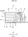
- FIG. 8 is a cross-sectional view taken along line IIX-IIX of the battery module shown in FIG. 2
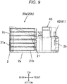
- FIG. 9 is a side view for describing a disposition relationship between the battery group and the housing.
- FIG. 9 a perspective view of an internal structure of the case body 2 is shown in order to make the understanding of the structure easy.
- the battery module 10 is fixed to an inner surface of the bottom surface 2a (one side surface) of the case body 2 by inserting a mounting member such as a bolt into the mounting hole 34f of the fixing piece 34e of the end plate 34 shown in FIG. 3 . For this reason, the end plate 34 of the battery module 10 is in contact with the bottom surface 2a of the case body 2.
- the battery module 10 is fixed to the case body 2 in a state in which the bottom surfaces 21a of the respective secondary battery cells 21 of the battery groups 20a and 20b are in contact with the inner surface of the rear side surface 2c of the case body.
- a height (length in the top and bottom direction) of the rear side surface 2c of the case body 2 is higher than that of the battery groups 20a and 20b.
- the bottom surfaces 21a of all of the secondary battery cells 21 of the battery groups 20a and 20b are in contact with the rear side surface 2c of the case body 2. That is, the battery module 10 is coupled to the bottom surface 2a and the rear side surface 2c of the case body 2 so as to be capable of conducting heat to the bottom surface 2a and the rear side surface 2c of the case body 2.
- each of the secondary battery cells 21 constituting the battery groups 20a and 20b heat generated in each of the secondary battery cells 21 constituting the battery groups 20a and 20b is conducted to the bottom surface 2a and the rear side surface 2c of the case body 2, such that each of the secondary battery cells 21 is cooled by the case body 2.
- Each of the secondary battery cells 21 of the battery groups 20a and 20b is conducted to the bottom surface 2a of the case body 2 through the center plate 35.
- a height (length in the top and bottom direction) of the front side surface 2b of the case body 2 is lower than that of the battery groups 20a and 20b.
- the pack positive electrode terminal 62 and the pack negative electrode terminal 61 fixed to the holder 41 of the contactor module 40 are disposed at positions higher than the upper surface of the front side surface 2b of the case body 2. For this reason, it is possible to easily and efficiently perform a work of accommodating the battery module 10 and the contactor module 40 in the case body 2. In addition, it is possible to easily and efficiently assemble the pack positive electrode terminal 62, the bus bar 62a for connection, the pack negative electrode terminal 61, and the bus bar 61a for connection to the holder 41.
- each of the pack positive electrode terminal 62 and the pack negative electrode terminal 61 is disposed at a position higher than an upper end of the front side surface 2b of the case body 2. For this reason, it is possible to easily perform a work of connecting high voltage (HV) cables to the pack positive electrode terminal 62 and the pack negative electrode terminal 61.
- HV high voltage
- the respective secondary battery cells 21 of the battery module 10 are disposed so that the positive and negative electrode terminals 38 and 39 are directed toward the inside of the case body 2, that is, toward the contactor module 40.
- the bus bars 32a and 32b of the battery module 10 and the bus bars 63a and 63b for connection of the contactor module 40 are connected to each other, respectively.
- the pack negative electrode terminal 61, the pack positive electrode terminal 62, and the bus bars 61a, 62a, 63a, and 63b for connection are disposed at substantially the same height. For this reason, it is possible to reduce lengths of the bus bars 61a, 62a, 63a, and 63b for connection, and it is thus possible to suppress a voltage drop at the time of performing charging or discharging.
- the upper ends of the pack positive electrode terminal 62 and the pack negative electrode terminal 61 are disposed at the position lower than the upper surface of the battery module 10.
- the pack positive electrode terminal 62 and the pack negative electrode terminal 61 are disposed adjacent to the rear side surface 2c of the case body 2 on which the battery module 10 is disposed, the pack positive electrode terminal 62 and the pack negative electrode terminal 61 have a structure in which they protrude upward of the battery module 10.
- the pack positive electrode terminal 62 and the pack negative electrode terminal 61 are disposed adjacent to the front side surface 2b opposite to the rear side surface 2c of the case body 2 on which the battery module 10 is disposed, and it is thus possible to dispose the upper ends of the pack positive electrode terminal 62 and the pack negative electrode terminal 61 at the position lower than the upper surface of the battery module 10. As a result, it is possible to lower a height of the cell pack 1.
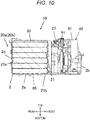
- FIG. 10 is a cross-sectional view showing a modified example of a thermal coupling structure between the battery groups and the housing, and corresponds to FIG. 8 .
- the respective battery groups 20a and 20b of the battery module 10 have a structure in which they are in contact with the bottom surface 2a of the case body 2 through the end plate 34.
- the respective electrode groups 20a and 20b are in direct contact with the bottom surface 2a of the case body 2.
- the end plate is not disposed below the battery groups 20a and 20b, and only the end plate 33 is disposed above the battery groups 20a and 20b.
- the end plate 33 is fixed to a boss (not shown) provided on the case body 2 by a fastening member, and secures the battery groups 20a and 20b to the bottom surface 2a of the case body 2.
- the battery groups 20a and 20b are coupled to the bottom surface 2a of the case body 2 so as to be capable of conducting the heat to the bottom surface 2a of the case body 2.
- a heat radiation sheet 65 (denoted by dotted lines) may be interposed between the secondary battery cells 21 of the lowermost layers of the battery groups 20a and 20b and the bottom surface 2a of the case body 2.
- a heat radiation sheet 65 may be interposed between the end plate 34 and the bottom surface 2a of the case body 2.
- the plate-shaped member disposed between the secondary battery cells 21 of the lowermost layers of the battery groups 20a and 20b and the bottom surface 2a of the case body 2 is limited to a member that has a function of securing the battery groups 20a and 20b, and may be a member that does not have a function of securing the battery groups 20a and 20b.
- the cell pack 1 can be installed in a state in which the bottom surface 2a of the case body 2 has a horizontal attitude, but can be also installed in a state in which the bottom surface 2a of the case body 2 has a vertical attitude.
- the structure in which the two battery groups 20a and 20b are accommodated in the housing has been described by way of example.
- the number of battery groups accommodated in the housing can be one or three or more.
- the number of secondary battery cells 21 of each battery group 20a and 20b is six has been described by way of example, the number of secondary battery cells 21 of each battery group 20a and 20b is not limited thereto, and can be arbitrarily increased or decreased.
- the inclined portions inclined in a straight line shape are formed on the left side surface 2e and the right side surface 2f of the case body 2
- the inclined portions may not have the straight line shape, but can have a curved shape, or portions having a stepped shape can be provided instead of the inclined portions.
- the cell pack having the lithium ion secondary battery cells has been described by way of example.
- the invention can be applied to a cell pack having secondary battery cells other than the lithium ion secondary battery cells, such as nickel hydrogen battery cells, lead battery cells, or nickel cadmium battery cells.
- the invention can also be applied to a cell pack having power storage elements such as lithium ion capacitors.
- the contactor module 40 includes the electrical components such as the board 42, the relay 43, the fuse 44, and the shunt resistor 45 has been described by way of example.
- a type or the number of electrical components included in the contactor module 40 may be increased or decreased as compared with that described above.
Landscapes
- Chemical & Material Sciences (AREA)
- Chemical Kinetics & Catalysis (AREA)
- Electrochemistry (AREA)
- General Chemical & Material Sciences (AREA)
- Engineering & Computer Science (AREA)
- Manufacturing & Machinery (AREA)
- Battery Mounting, Suspending (AREA)
- Secondary Cells (AREA)
Abstract
Description
- The present invention relates to a cell pack.
- In recent years, a cell pack including a battery group including a plurality of lithium ion secondary batteries is used as a power supply of an electric vehicle, a hybrid electric vehicle, or an electric device.
- Since a secondary battery cell generates heat due to a current flowing therein at the time of being charged and internal resistance, many cell packs have a cooling function
- As an example of such a conventional cell pack, a structure having a cooling device in which heat distribution pipes having flow paths of a refrigerant are disposed on a bottom surface of a battery group housed in a housing with a heat transfer sheet interposed therebetween and a heat radiation member having heat radiation fins is disposed to be closely adhered to the heat dispersion pipe has been known (see, for example, PTL 1).
- PTL 1:
JP 2012-018915 A - Since the cell pack described in
PTL 1 has a complicated cooling structure, workability of assembly of the cell pack is poor. - According to an aspect of the invention, a cell pack includes a battery group which includes a plurality of secondary battery cells each having a pair of wide-width surfaces, a pair of narrow-width surfaces, a bottom surface, and an external terminal formed to face the bottom surface; a housing which has one side surface, another side surface adjacent to the one side surface, and a facing side surface facing the other side surface and houses the battery group; and a pack external terminal which is disposed adjacent to the facing side surface of the housing and is connected to the external terminal of the battery group, wherein the secondary battery cells of the battery group are stacked so that the wide-width surfaces face each other, the battery group is housed in the housing in a state in which a wide-width surface of a secondary battery cell of a lowermost layer and the one side surface of the housing are coupled to each other so as to be capable of conducting heat therebetween and the bottom surfaces of the secondary battery cells and the other side surface of the housing are coupled to each other so as to be capable of conducting heat therebetween, and a height of the facing side surface of the housing is lower than that of the other side surface.
- According to the invention, a structure is simplified, such that workability of assembly can be improved.
-
- [
FIG. 1] FIG. 1 is a perspective view showing an appearance of a cell pack according to an embodiment of the invention. - [
FIG. 2] FIG. 2 is a perspective view of the cell pack shown inFIG. 1 in a state in which an upper cover of the cell pack is opened. - [
FIG. 3] FIG. 3 is a perspective view of a battery module shown inFIG. 2 . - [
FIG. 4] FIG. 4 is an exploded perspective view of the battery module shown inFIG. 3 in a state in which a bus bar case of the battery module is removed. - [
FIG. 5] FIG. 5 is an exploded perspective view of battery groups shown inFIG. 4 . - [
FIG. 6] FIG. 6 is a perspective view of a contactor module shown inFIG. 2 . - [
FIG. 7] FIG. 7 is a perspective view of the contactor module shown inFIG. 6 when viewed from a rear side. - [
FIG. 8] FIG. 8 is a cross-sectional view taken along line IIX-IIX of the battery module shown inFIG. 2 . - [
FIG. 9] FIG. 9 is a side view for describing a disposition relationship between the battery groups and a housing. - [
FIG. 10] FIG. 10 is a cross-sectional view showing a modified example of a thermal coupling structure between the battery groups and the housing. - Hereinafter, a cell pack according to an embodiment of the invention will be described with reference to the drawings.
-
FIG. 1 is a perspective view showing an appearance of a cell pack according to an embodiment of the invention, andFIG. 2 is a perspective view of the cell pack shown inFIG. 1 in a state in which an upper cover of the cell pack is opened. - A
cell pack 1 has a housing including acase body 2 and anupper cover 3. Thecase body 2 and theupper cover 3 are formed of a resin or a metal. Thecase body 2 has abottom surface 2a, afront side surface 2b, arear side surface 2c, aleft side surface 2d, and aright side surface 2e, and is formed in a box shape of which an inner portion is a space. - In the following description, a left and right direction, a front and rear direction, and a top and bottom direction are defined as shown.
- The
front side surface 2b of thecase body 2 is formed to be lower than therear side surface 2c. Theleft side surface 2d and theright side surface 2e of thecase body 2 have flat portions of which upper end surfaces have the same height as that of thefront side surface 2b and inclined portions extending from the flat portions to an upper end surface of thefront side surface 2b. Theupper cover 3 has anupper surface 3a, afront side surface 3b, arear side surface 3c, aleft side surface 3d, and aright side surface 3e. Thefront side surface 3b of theupper cover 3 is formed to be higher than therear side surface 3c. Theleft side surface 3d and theright side surface 3e of theupper cover 3 have flat portions of which lower end surfaces have the same height as that of thefront side surface 3b and inclined portions extending from the flat portions to a lower end surface of therear side surface 3c. Thecase body 2 and theupper cover 3 are formed so that lengths of the flat portions and lengths and inclination angles of the inclined portions of each of them are substantially the same as each other, and are combined with each other so that ahousing 4 has a rectangular parallelepiped shape. -
Recesses upper cover 3, respectively. Openings are formed in bottom portions of therecesses negative electrode terminal 61 protrudes outward from the opening of therecess 13a and a packpositive electrode terminal 62 protrudes outward from the opening of therecess 13b. In addition, asignal connector 4 is mounted on a bottom surface of therecess 13b. The packnegative electrode terminal 61 and the packpositive electrode terminal 62 are disposed at a position higher than thefront side surface 2b of thecase body 2. However, an upper end of each of the packnegative electrode terminal 61 and the packpositive electrode terminal 62 is disposed at a position lower than an upper surface of abattery module 10 to be described below. A wiring member inserted into an opening provided in a side surface of therecess 13b is connected to thesignal connector 4 of thecase body 2. - The
battery module 10 and acontactor module 40 are housed in thecase body 2. Thebattery module 10 is disposed at a position corresponding to the inclined portions of theleft side surface 2d and theright side surface 2e of thecase body 2, that is, a rear side of thecase body 2. Thecontactor module 40 is disposed at a position corresponding to the flat portions of theleft side surface 2d and theright side surface 2e of thecase body 2, that is, a front side of thecase body 2. In the present embodiment, thebattery module 10 will be described as a battery module having prismatic lithium ion secondary battery cells. -
FIG. 3 is a perspective view of a battery module shown inFIG. 2 , andFIG. 4 is an exploded perspective view of battery groups shown inFIG. 3 .FIG. 5 is an exploded perspective view of the battery groups shown inFIG. 4 . - The
battery module 10 includes twobattery groups bus bar case 27 disposed in front of thebattery groups lower end plates right side plates 36, and acenter plate 35. Theend plates side plates 36, and thecenter plate 35 are formed of a metal such as aluminum. - As shown in
FIG. 5 , therespective battery groups battery group 20a and thebattery group 20b have the same structure. Thesecondary battery cell 21 has a thin rectangular parallelepiped shape, and has a battery container including a battery can having abottom surface 21a, a pair of wide-width surfaces 21b and a pair of narrow-width surfaces 21c and a battery lid provided to cover an opening (not shown) formed to face thebottom surface 21a of the battery can and sealing the battery can. The respectivesecondary battery cells 21 are stacked in the top and bottom direction with the wide-width surfaces 21b thereof facing each other.Insulating plates 24 are disposed betweensecondary battery cells 21 vertically adjacent to each other, above asecondary battery cell 21 of the uppermost layer, and below asecondary battery cell 21 of the lowermost layer. Theinsulating plate 24 is formed of, for example, polybutylene terephthalate (PBT). - A
positive electrode terminal 38 and anegative electrode terminal 39 are mounted on the battery lid of thesecondary battery cell 21 in a state in which they are insulated from the battery lid 23. Although not shown, a positive electrode connection portion and a negative electrode connection portion of a power generation element housed in the battery container are connected to thepositive electrode terminal 38 and thenegative electrode terminal 39, respectively. The respectivesecondary battery cells 21 are alternately stacked with the othersecondary battery cells 21 vertically adjacent thereto with front and back surfaces of the pair of wide-width surfaces 21b inverted so that apositive electrode terminal 38 of onesecondary battery cell 21 and anegative electrode terminal 39 of the othersecondary battery cell 21 face each other. - The
positive electrode terminal 38 of onesecondary battery cell 21 and thenegative electrode terminal 39 of the othersecondary battery cell 21 vertically adjacent to each other are connected to each other by an inter-cell bus bar 31 (seeFIG. 3 ). Thepositive electrode terminal 38 and thenegative electrode terminal 39, and theinter-cell bus bar 31 are joined to each other by, for example, welding. As a result, the plurality ofsecondary battery cells 21 constituting each of thebattery groups - A
positive electrode terminal 38a of the uppermost layer of thebattery group 20a is disposed in the vicinity of theleft battery group 20b, and becomes the highest potential portion of thebattery group 20a. Anegative electrode terminal 39a of the lowermost layer of thebattery group 20a is disposed in the vicinity of theleft battery group 20b, and becomes the lowest potential portion of thebattery group 20a. Apositive electrode terminal 38b of the lowermost layer of thebattery group 20b is disposed in the vicinity of theright battery group 20a, and becomes the highest potential portion of thebattery group 20b. Thenegative electrode terminal 39a of the lowest potential of thebattery group 20a and thepositive electrode terminal 38b of the highest potential of thebattery group 20b are connected to each other by an inter-group bus bar (not shown) . Anegative electrode terminal 39b of the uppermost layer of theleft battery group 20b is disposed in the vicinity of thebattery group 20a, and is the lowest potential portion of thebattery group 20b. In this manner, thebattery group 20a and thebattery group 20b are electrically connected to each other in series, thepositive electrode terminal 38a of the uppermost layer of theelectrode group 20a is the highest potential portion of thebattery group 20a and thebattery group 20b, and thenegative electrode terminal 39b of the uppermost layer of thebattery group 20b becomes the lowest potential portion of thebattery group 20a and thebattery group 20b. - The
battery group 20a and thebattery group 20b are disposed on the left and the right of thecenter plate 35, respectively. Theside plates 36 are disposed on a right side surface of thebattery group 20a and a left side surface of thebattery group 20b, respectively. Pins 37 (seeFIG. 4 ) are provided on upper and lower surfaces of eachside plate 36. Theend plates battery groups center plate 35, and the pair ofside plates 36, respectively. As shown inFIG. 4 , theend plates portions side plates 36 and mountingportions center plate 35, respectively. The mountingportions positioning holes holes portions holes piece 34e having a mountinghole 34f is formed in theend plate 34. - The
battery module 10 is configured in a state in which thesecondary battery cells 21 constituting thebattery groups center plate 35 by the pair ofside plates 36 and are pressed from top and bottom directions through the insulatingplates 24 by the pair ofend plates - The
center plate 35, thebattery groups side plates 36 are disposed on theend plate 34, and thebattery groups center plate 35 side through theside plates 36. In this case, a heat transfer sheet may be interposed between each of thebattery groups center plate 35. In this manner, positions of thepins 37 of theside plates 36 in the left and right directions are made to coincide with therespective positioning holes 34c of theend plate 34. Then, thepins 37 of therespective side plates 36 are inserted into the positioning holes 34c of theend plate 34. In this state, fastening members such as bolts are inserted into the through-holes 34d of theend plate 34 to fix thecenter plate 35 and the pair ofside plates 36 to theend plate 34. - Similarly, the positioning holes 33c of the
end plate 33 are aligned with thepins 37 of therespective side plates 36, thepins 37 of therespective side plates 36 are inserted into the positioning holes 33c of theend plate 33, and fastening members such as bolts are inserted into the through-holes 33d of theend plate 33 to fix theend plate 33 to thecenter plate 35 and the pair ofside plates 36. - In this manner, the
battery module 10 in which thesecondary battery cells 21 constituting thebattery groups - In the abovementioned embodiment, each of the
battery groups end plates battery groups end plates - In addition, the
battery groups end plates battery groups end plates side plates 36 on the left end side and the right end side of thebattery groups center plate 35 in a central portion. For this reason, warpage of theend plates end plates - As shown in
FIG. 3 , thebus bar case 27 is disposed on a front surface side of thebattery groups bus bar case 27 covers front surfaces of thebattery groups inter-cell bus bar 31 in a state in which the front surfaces of thebattery groups inter-cell bus bar 31 are partially exposed. Aterminal disposition portion 28 is provided on a front surface of thebus bar case 27. A separatingwall 28a protruding upward is formed at the center of theterminal disposition portion 28 in the left and right direction. An upper surface of theterminal disposition portion 28 is separated into a positive electrodeterminal disposition surface 28b and a negative electrodeterminal disposition surface 28c by the separatingwall 28a. A distal end portion of abus bar 32a connected to thepositive electrode terminal 38a, which is the highest potential portion of thebattery groups terminal disposition surface 28b. A distal end portion of abus bar 32b connected to thenegative electrode terminal 39b, which is the lowest potential portion of thebattery groups terminal disposition surface 28c. -
FIG. 6 is a perspective view of a contactor module shown inFIG. 2 , andFIG. 7 is a perspective view of the contactor module shown inFIG. 6 when viewed from a rear side. - The
contactor module 40 includes aholder 41 and electrical components such as aboard 42, a relay (contactor) 43, afuse 44, and ashunt resistor 45 accommodated in theholder 41. A positive electrodeterminal fixing portion 41a and a negative electrodeterminal fixing portion 41b that protrude forward are formed in theholder 41. The packpositive electrode terminal 62 is fixed on the positive electrodeterminal fixing portion 41a, and the packnegative electrode terminal 61 is fixed on the negative electrodeterminal fixing portion 41b. Theshunt resistor 45 is mounted on theboard 42 by fastening members such as screws. Theshunt resistor 45 limits a current at the time of applying a power to prevent occurrence of abnormality. One end of theshunt resistor 45 is connected to the packnegative electrode terminal 61 through abus bar 61a for connection. - The
board 42 is mounted on theholder 41 by fastening members such as bolts on a side facing thebattery module 10, in other words, on a rear surface side of theholder 41. Theinter-cell bus bar 31 is connected to theboard 42 to measure and monitor voltages of the respectivesecondary battery cells 21, and circuits that constitute a battery management system (BMS) that monitors and controls theentire cell pack 1 is mounted on theboard 42. - The
relay 43 and thefuse 44 are mounted on theholder 41 by fastening members such as screws. One end of therelay 43 and one end of thefuse 44 are connected to each other by a bus bar. The other end of thefuse 44 is connected to the packpositive electrode terminal 62 through abus bar 62a for connection. The other end of therelay 43 is connected to abus bar 63a for connection. Thebus bar 63a for connection is connected to thebus bar 32a (seeFIG. 3 ) mounted on thebus bar case 27 of thebattery module 10. Thebus bar 63a for connection and thebus bar 32a are connected to each other by inserting a fastening member such as a bolt 91 (seeFIG. 8 ) into through-holes provided in thebus bar 63a for connection and thebus bar 32a to fix thebus bar 63a for connection and thebus bar 32a to each other. In this manner, voltage paths between the packpositive electrode terminal 62 and positive electrode sides of thebattery groups relay 43 and thefuse 44 are electrical components for a safety device for ensuring safety at the time of maintenance and inspection. - The other end of the
shunt resistor 45 is connected to thebus bar 32b (seeFIG. 3 ) mounted on thebus bar case 27 of thebattery module 10 through abus bar 63b for connection. Thebus bar 63b for connection and thebus bar 32b are connected to each other by inserting a fastening member such as a bolt 91 (seeFIG. 8 ) into through-holes provided in thebus bar 63b for connection and thebus bar 32b to fix thebus bar 63b for connection and thebus bar 32b to each other. In this manner, voltage paths between the packnegative electrode terminal 61 and negative electrode sides of thebattery groups - That is, the pack
positive electrode terminal 62 is connected to the highest potential portion of thebattery groups battery module 10 through the electrical components mounted in thecontactor module 40, and the packnegative electrode terminal 61 is connected to the lowest potential portion of thebattery groups battery module 10 through the electrical components mounted in thecontactor module 40. -
FIG. 8 is a cross-sectional view taken along line IIX-IIX of the battery module shown inFIG. 2 , andFIG. 9 is a side view for describing a disposition relationship between the battery group and the housing. InFIG. 9 , a perspective view of an internal structure of thecase body 2 is shown in order to make the understanding of the structure easy. - The
battery module 10 is fixed to an inner surface of thebottom surface 2a (one side surface) of thecase body 2 by inserting a mounting member such as a bolt into the mountinghole 34f of the fixingpiece 34e of theend plate 34 shown inFIG. 3 . For this reason, theend plate 34 of thebattery module 10 is in contact with thebottom surface 2a of thecase body 2. Thebattery module 10 is fixed to thecase body 2 in a state in which the bottom surfaces 21a of the respectivesecondary battery cells 21 of thebattery groups rear side surface 2c of the case body. A height (length in the top and bottom direction) of therear side surface 2c of thecase body 2 is higher than that of thebattery groups secondary battery cells 21 of thebattery groups rear side surface 2c of thecase body 2. That is, thebattery module 10 is coupled to thebottom surface 2a and therear side surface 2c of thecase body 2 so as to be capable of conducting heat to thebottom surface 2a and therear side surface 2c of thecase body 2. - Therefore, heat generated in each of the
secondary battery cells 21 constituting thebattery groups bottom surface 2a and therear side surface 2c of thecase body 2, such that each of thesecondary battery cells 21 is cooled by thecase body 2. Each of thesecondary battery cells 21 of thebattery groups bottom surface 2a of thecase body 2 through thecenter plate 35. - As shown in
FIG. 9 , a height (length in the top and bottom direction) of thefront side surface 2b of thecase body 2 is lower than that of thebattery groups positive electrode terminal 62 and the packnegative electrode terminal 61 fixed to theholder 41 of thecontactor module 40 are disposed at positions higher than the upper surface of thefront side surface 2b of thecase body 2. For this reason, it is possible to easily and efficiently perform a work of accommodating thebattery module 10 and thecontactor module 40 in thecase body 2. In addition, it is possible to easily and efficiently assemble the packpositive electrode terminal 62, thebus bar 62a for connection, the packnegative electrode terminal 61, and thebus bar 61a for connection to theholder 41. - The upper end of each of the pack
positive electrode terminal 62 and the packnegative electrode terminal 61 is disposed at a position higher than an upper end of thefront side surface 2b of thecase body 2. For this reason, it is possible to easily perform a work of connecting high voltage (HV) cables to the packpositive electrode terminal 62 and the packnegative electrode terminal 61. - The respective
secondary battery cells 21 of thebattery module 10 are disposed so that the positive andnegative electrode terminals case body 2, that is, toward thecontactor module 40. The bus bars 32a and 32b of thebattery module 10 and the bus bars 63a and 63b for connection of thecontactor module 40 are connected to each other, respectively. In addition, the packnegative electrode terminal 61, the packpositive electrode terminal 62, and thebus bars bus bars - The upper ends of the pack
positive electrode terminal 62 and the packnegative electrode terminal 61 are disposed at the position lower than the upper surface of thebattery module 10. When the packpositive electrode terminal 62 and the packnegative electrode terminal 61 are disposed adjacent to therear side surface 2c of thecase body 2 on which thebattery module 10 is disposed, the packpositive electrode terminal 62 and the packnegative electrode terminal 61 have a structure in which they protrude upward of thebattery module 10. In the present embodiment, the packpositive electrode terminal 62 and the packnegative electrode terminal 61 are disposed adjacent to thefront side surface 2b opposite to therear side surface 2c of thecase body 2 on which thebattery module 10 is disposed, and it is thus possible to dispose the upper ends of the packpositive electrode terminal 62 and the packnegative electrode terminal 61 at the position lower than the upper surface of thebattery module 10. As a result, it is possible to lower a height of thecell pack 1. -
FIG. 10 is a cross-sectional view showing a modified example of a thermal coupling structure between the battery groups and the housing, and corresponds toFIG. 8 . - In the abovementioned embodiment, the
respective battery groups battery module 10 have a structure in which they are in contact with thebottom surface 2a of thecase body 2 through theend plate 34. On the other hand, in the modified example shown inFIG. 10 , therespective electrode groups bottom surface 2a of thecase body 2. - In a structure shown in the modified example, the end plate is not disposed below the
battery groups end plate 33 is disposed above thebattery groups end plate 33 is fixed to a boss (not shown) provided on thecase body 2 by a fastening member, and secures thebattery groups bottom surface 2a of thecase body 2. As a result, thebattery groups bottom surface 2a of thecase body 2 so as to be capable of conducting the heat to thebottom surface 2a of thecase body 2. - Other configurations in the modified example are the same as those in the abovementioned embodiment, and the same members will be denoted by the same reference numerals and a description thereof will be omitted.
- In the structure shown in
FIG. 10 , a heat radiation sheet 65 (denoted by dotted lines) may be interposed between thesecondary battery cells 21 of the lowermost layers of thebattery groups bottom surface 2a of thecase body 2. In addition, in the structure shown inFIG. 8 , it is also possible to interpose aheat radiation sheet 65 between theend plate 34 and thebottom surface 2a of thecase body 2. - Further, in the structure shown in
FIG. 10 , it is also possible to interpose a plate-shaped member such as theend plate 34 between thesecondary battery cells 21 of the lowermost layers of thebattery groups bottom surface 2a of thecase body 2. In other words, the plate-shaped member disposed between thesecondary battery cells 21 of the lowermost layers of thebattery groups bottom surface 2a of thecase body 2 is limited to a member that has a function of securing thebattery groups battery groups - The
cell pack 1 can be installed in a state in which thebottom surface 2a of thecase body 2 has a horizontal attitude, but can be also installed in a state in which thebottom surface 2a of thecase body 2 has a vertical attitude. - According to the embodiment of the invention, the following effects are obtained.
- (1) The
battery groups secondary battery cells 21 so that the wide-width surfaces 21b face each other, and have a structure in which they are housed in the housing in a state in which the wide-width surface 21b of thesecondary battery cell 21 of the lowermost layer and one side surface (bottom surface 2a) of the housing are coupled to each other so as to be capable of conducting heat therebetween and the bottom surfaces 21a of thesecondary battery cells 21 and the other side surface (rear side surface 2c) of the housing are coupled to each other so as to be capable of conducting heat therebetween. For this reason, the heat generated in thesecondary battery cells 21 is conducted to thebottom surface 2a and therear side surface 2c of thecase body 2, such that thesecondary battery cells 21 are cooled by thecase body 2. As described above, since thecell pack 1 according to the present embodiment has a simple structure that does not have a cooling device having a flow path of a refrigerant for cooling thesecondary battery groups front side surface 2b) of the housing is lower than that of the other side surface (rear side surface 2c). For this reason, it is possible to mount thebattery module 10 or thecontactor module 40 in the housing in a state of gripping thebattery module 10 or thecontactor module 40 up to a deep position in the housing, such that it is possible to improve workability. - (2) The upper ends of pack external terminals (the pack
positive electrode terminal 62 and the pack negative electrode terminal 61) are disposed at the position higher than the upper end of the facing side surface (front side surface 2b) of the housing. For this reason, it is possible to easily perform the work of connecting the HV cables to the pack external terminals. - (3) The bottom surfaces 21a of all the
secondary battery cells 21 of thebattery groups rear side surface 2c) of the housing so as to be capable of conducting the heat to the other side surface (rear side surface 2c) of the housing. For this reason, it is possible to improve cooling performance of the housing cooling the respectivesecondary battery cells 21. - (4) The wide-
width surfaces 21b of thesecondary battery cells 21 of the lowermost layers of thebattery groups bottom surface 2a) of the housing are coupled to each other through the plate-shaped member (end plate 34) so as to be capable of conducting the heat therebetween. For this reason, it is also possible to adopt a structure in which the plate-shaped structure is used for both of a securing member securing thebattery groups battery groups electrode groups - (5) The wide-
width surfaces 21b of thesecondary battery cells 21 of the lowermost layers of thebattery groups - In the abovementioned embodiment, the structure in which the two
battery groups secondary battery cells 21 of eachbattery group secondary battery cells 21 of eachbattery group - In the abovementioned embodiment, a structure in which the inclined portions inclined in a straight line shape are formed on the
left side surface 2e and the right side surface 2f of thecase body 2 has been described by way of example. However, the inclined portions may not have the straight line shape, but can have a curved shape, or portions having a stepped shape can be provided instead of the inclined portions. - In the abovementioned embodiment, the cell pack having the lithium ion secondary battery cells has been described by way of example. However, the invention can be applied to a cell pack having secondary battery cells other than the lithium ion secondary battery cells, such as nickel hydrogen battery cells, lead battery cells, or nickel cadmium battery cells. In addition, the invention can also be applied to a cell pack having power storage elements such as lithium ion capacitors.
- In the abovementioned embodiment, a structure in which the
contactor module 40 includes the electrical components such as theboard 42, therelay 43, thefuse 44, and theshunt resistor 45 has been described by way of example. However, a type or the number of electrical components included in thecontactor module 40 may be increased or decreased as compared with that described above. - Various embodiments and modified examples have been described hereinabove, but the invention is not limited to these contents. Other aspects considered to be within the technical idea of the invention are also included in the scope of the invention.
- The disclosure contents of the following priority application are incorporated herein by reference.
- Japanese Patent Application No.
2017-019868 (filed on Feb 6, 2017 -
- 1
- cell pack
- 2
- case body
- 2a
- bottom surface (one side surface)
- 2b
- front side surface (facing side surface)
- 2c
- rear side surface (the other side surface)
- 10
- battery module
- 20a, 20b
- battery group
- 21
- secondary battery cell
- 21a
- bottom surface
- 21b
- wide-width surface
- 21c
- narrow-width surface
- 34
- end plate (plate-shaped member)
- 38, 38a, 38b
- positive electrode terminal (external terminal)
- 39, 39a, 39b
- negative electrode terminal (external terminal)
- 61
- pack negative electrode terminal (pack external terminal)
- 62
- pack negative electrode terminal (pack external terminal)
- 65
- heat radiation sheet
Claims (5)
- A cell pack comprising:a battery group which includes a plurality of secondary battery cells each having a pair of wide-width surfaces, a pair of narrow-width surfaces, a bottom surface, and an external terminal formed to face the bottom surface;a housing which has one side surface, another side surface adjacent to the one side surface, and a facing side surface facing the other side surface and houses the battery group; anda pack external terminal which is disposed adjacent to the facing side surface of the housing and is connected to the external terminal of the battery group,wherein the secondary battery cells of the battery group are stacked so that the wide-width surfaces face each other,the battery group is housed in the housing in a state in which a wide-width surface of a secondary battery cell of a lowermost layer and the one side surface of the housing are coupled to each other so as to be capable of conducting heat between the wide-width surface and the one side surface and the bottom surfaces of the secondary battery cells and the other side surface of the housing are coupled to each other so as to be capable of conducting heat between the bottom surfaces and the other side surface, anda height of the facing side surface of the housing is lower than that of the other side surface.
- The cell pack according to claim 1, wherein
an upper end of the pack external terminal is disposed at a position higher than an upper end of the facing side surface of the housing. - The cell pack according to claim 1, wherein
the bottom surfaces of all the secondary battery cells of the battery group are coupled to the other side surface of the housing so as to be capable of conducting heat to the other side surface of the housing. - The cell pack according to claim 1, wherein
the wide-width surface of the secondary battery cell of the lowermost layer of the battery group and the one side surface of the housing are coupled to each other with a plate-shaped member interposed between the wide-width surface and the one side surface so as to be capable of conducting the heat between the wide-width surface and the one side surface. - The cell pack according to claim 1, wherein
the wide-width surface of the secondary battery cell of the lowermost layer of the battery group and the one side surface of the housing are coupled to each other with a heat radiation sheet interposed between the wide-width surface and the one side surface so as to be capable of conducting the heat between the wide-width surface and the one side surface.
Applications Claiming Priority (2)
| Application Number | Priority Date | Filing Date | Title |
|---|---|---|---|
| JP2017019868 | 2017-02-06 | ||
| PCT/JP2018/003857 WO2018143463A1 (en) | 2017-02-06 | 2018-02-05 | Cell pack |
Publications (2)
| Publication Number | Publication Date |
|---|---|
| EP3579297A1 true EP3579297A1 (en) | 2019-12-11 |
| EP3579297A4 EP3579297A4 (en) | 2020-12-02 |
Family
ID=63040804
Family Applications (1)
| Application Number | Title | Priority Date | Filing Date |
|---|---|---|---|
| EP18747214.7A Withdrawn EP3579297A4 (en) | 2017-02-06 | 2018-02-05 | Cell pack |
Country Status (5)
| Country | Link |
|---|---|
| US (1) | US20190280353A1 (en) |
| EP (1) | EP3579297A4 (en) |
| JP (1) | JPWO2018143463A1 (en) |
| CN (2) | CN109643780A (en) |
| WO (1) | WO2018143463A1 (en) |
Cited By (1)
| Publication number | Priority date | Publication date | Assignee | Title |
|---|---|---|---|---|
| EP3657567A4 (en) * | 2017-07-20 | 2021-04-28 | Vehicle Energy Japan Inc. | BATTERY BLOCK |
Families Citing this family (5)
| Publication number | Priority date | Publication date | Assignee | Title |
|---|---|---|---|---|
| KR102088477B1 (en) * | 2017-05-16 | 2020-03-12 | 주식회사 엘지화학 | Battery module |
| JP7070259B2 (en) * | 2018-09-06 | 2022-05-18 | 株式会社デンソー | Battery pack |
| KR102798546B1 (en) * | 2019-10-18 | 2025-04-18 | 주식회사 엘지에너지솔루션 | Battery module |
| CN115548546A (en) * | 2021-06-30 | 2022-12-30 | 比亚迪股份有限公司 | Battery Packs and Electric Vehicles |
| CN114865241B (en) * | 2022-05-13 | 2024-01-26 | 星恒电源股份有限公司 | Battery cell set, battery module and assembling method |
Family Cites Families (8)
| Publication number | Priority date | Publication date | Assignee | Title |
|---|---|---|---|---|
| JP2003059471A (en) * | 2001-08-20 | 2003-02-28 | Sony Corp | Battery housing |
| JP2009252553A (en) * | 2008-04-07 | 2009-10-29 | Furukawa Battery Co Ltd:The | Battery pack module |
| JP2012099288A (en) * | 2010-10-29 | 2012-05-24 | Primearth Ev Energy Co Ltd | Battery pack |
| KR101252952B1 (en) * | 2011-05-02 | 2013-04-15 | 로베르트 보쉬 게엠베하 | Battery module for preventing movement of battery cell |
| KR101652653B1 (en) * | 2012-12-27 | 2016-08-30 | 닛산 지도우샤 가부시키가이샤 | Battery module and battery pack |
| JP2015022848A (en) * | 2013-07-17 | 2015-02-02 | 三井造船株式会社 | Battery module and method for manufacturing battery module |
| KR101841801B1 (en) * | 2014-06-11 | 2018-05-04 | 주식회사 엘지화학 | Battery pack having bushing for coupling end plate |
| JP6390524B2 (en) * | 2015-06-03 | 2018-09-19 | 株式会社デンソー | Battery pack |
-
2018
- 2018-02-05 EP EP18747214.7A patent/EP3579297A4/en not_active Withdrawn
- 2018-02-05 WO PCT/JP2018/003857 patent/WO2018143463A1/en not_active Ceased
- 2018-02-05 US US16/334,206 patent/US20190280353A1/en not_active Abandoned
- 2018-02-05 CN CN201880003259.8A patent/CN109643780A/en active Pending
- 2018-02-05 JP JP2018566160A patent/JPWO2018143463A1/en not_active Ceased
- 2018-02-06 CN CN201820202925.8U patent/CN208127265U/en not_active Expired - Fee Related
Cited By (2)
| Publication number | Priority date | Publication date | Assignee | Title |
|---|---|---|---|---|
| EP3657567A4 (en) * | 2017-07-20 | 2021-04-28 | Vehicle Energy Japan Inc. | BATTERY BLOCK |
| US11228069B2 (en) | 2017-07-20 | 2022-01-18 | Vehicle Energy Japan Inc. | Battery pack |
Also Published As
| Publication number | Publication date |
|---|---|
| US20190280353A1 (en) | 2019-09-12 |
| JPWO2018143463A1 (en) | 2019-06-27 |
| CN208127265U (en) | 2018-11-20 |
| EP3579297A4 (en) | 2020-12-02 |
| WO2018143463A1 (en) | 2018-08-09 |
| CN109643780A (en) | 2019-04-16 |
Similar Documents
| Publication | Publication Date | Title |
|---|---|---|
| US20190280353A1 (en) | Cell Pack | |
| KR101287107B1 (en) | Battery module with connecting member | |
| JP7566139B2 (en) | Battery module including multiple parallel battery cells | |
| CN104704649B (en) | Battery module with busbar assembly and the battery pack including the battery module | |
| EP2808921B1 (en) | Battery module | |
| US20240250368A1 (en) | Battery Module Comprising Module Housing | |
| KR20220101581A (en) | Battery pack and vehicle comprising the battery pack | |
| US20200259135A1 (en) | Secondary battery pack including cell frame with coating prevention part | |
| US20220037707A1 (en) | Battery Pack and Holder | |
| CN102822687A (en) | Voltage detection component for battery module and battery module including the voltage detection component | |
| US12183952B2 (en) | Battery pack with enhanced structure for preventing short circuit and shock | |
| US20240291058A1 (en) | Cell Module Assembly and Battery Pack Comprising the Same | |
| CN111433936B (en) | Battery pack connector and battery pack including same | |
| US11228069B2 (en) | Battery pack | |
| KR20210046342A (en) | Battery pack and device including the same | |
| KR20160052018A (en) | Battery Module Having Mounting Means of Bus Bar and External Input-Output Terminal | |
| KR20210155526A (en) | Battery module and battery pack including the same | |
| US20220336911A1 (en) | Battery pack including high voltage wire assembly and method for manufacturing the battery pack | |
| CN116114104A (en) | Battery modules, battery packs and power storage devices | |
| JP7174482B2 (en) | battery module | |
| CN119560733A (en) | Battery module and method for manufacturing battery module | |
| JP2024050379A (en) | Battery pack and method for manufacturing the battery pack | |
| KR20140052442A (en) | Battery pack | |
| EP4362183A1 (en) | Battery module | |
| KR20230068997A (en) | Battery module, battery pack and vehicle comprising the battery module |
Legal Events
| Date | Code | Title | Description |
|---|---|---|---|
| STAA | Information on the status of an ep patent application or granted ep patent |
Free format text: STATUS: THE INTERNATIONAL PUBLICATION HAS BEEN MADE |
|
| PUAI | Public reference made under article 153(3) epc to a published international application that has entered the european phase |
Free format text: ORIGINAL CODE: 0009012 |
|
| STAA | Information on the status of an ep patent application or granted ep patent |
Free format text: STATUS: REQUEST FOR EXAMINATION WAS MADE |
|
| 17P | Request for examination filed |
Effective date: 20190906 |
|
| AK | Designated contracting states |
Kind code of ref document: A1 Designated state(s): AL AT BE BG CH CY CZ DE DK EE ES FI FR GB GR HR HU IE IS IT LI LT LU LV MC MK MT NL NO PL PT RO RS SE SI SK SM TR |
|
| AX | Request for extension of the european patent |
Extension state: BA ME |
|
| RAP1 | Party data changed (applicant data changed or rights of an application transferred) |
Owner name: VEHICLE ENERGY JAPAN INC. |
|
| DAV | Request for validation of the european patent (deleted) | ||
| DAX | Request for extension of the european patent (deleted) | ||
| A4 | Supplementary search report drawn up and despatched |
Effective date: 20201030 |
|
| RIC1 | Information provided on ipc code assigned before grant |
Ipc: H01M 10/6554 20140101ALI20201026BHEP Ipc: H01M 2/02 20060101ALI20201026BHEP Ipc: H01M 10/613 20140101ALI20201026BHEP Ipc: H01M 10/647 20140101ALI20201026BHEP Ipc: H01M 2/10 20060101AFI20201026BHEP |
|
| STAA | Information on the status of an ep patent application or granted ep patent |
Free format text: STATUS: THE APPLICATION HAS BEEN WITHDRAWN |
|
| 18W | Application withdrawn |
Effective date: 20210421 |