EP3579033A1 - Cladding mode light removal structure and laser device - Google Patents
Cladding mode light removal structure and laser device Download PDFInfo
- Publication number
- EP3579033A1 EP3579033A1 EP18776255.4A EP18776255A EP3579033A1 EP 3579033 A1 EP3579033 A1 EP 3579033A1 EP 18776255 A EP18776255 A EP 18776255A EP 3579033 A1 EP3579033 A1 EP 3579033A1
- Authority
- EP
- European Patent Office
- Prior art keywords
- cladding
- refractive index
- optical fiber
- output
- input
- Prior art date
- Legal status (The legal status is an assumption and is not a legal conclusion. Google has not performed a legal analysis and makes no representation as to the accuracy of the status listed.)
- Withdrawn
Links
- 238000005253 cladding Methods 0.000 title claims abstract description 308
- 239000013307 optical fiber Substances 0.000 claims abstract description 164
- 239000011347 resin Substances 0.000 claims abstract description 87
- 229920005989 resin Polymers 0.000 claims abstract description 87
- 239000000835 fiber Substances 0.000 claims abstract description 60
- 230000004927 fusion Effects 0.000 claims abstract description 44
- 230000004308 accommodation Effects 0.000 claims abstract description 12
- 238000005086 pumping Methods 0.000 claims description 36
- 230000003321 amplification Effects 0.000 claims description 29
- 238000003199 nucleic acid amplification method Methods 0.000 claims description 29
- NCGICGYLBXGBGN-UHFFFAOYSA-N 3-morpholin-4-yl-1-oxa-3-azonia-2-azanidacyclopent-3-en-5-imine;hydrochloride Chemical compound Cl.[N-]1OC(=N)C=[N+]1N1CCOCC1 NCGICGYLBXGBGN-UHFFFAOYSA-N 0.000 claims description 5
- 229910052761 rare earth metal Inorganic materials 0.000 claims description 5
- 230000020169 heat generation Effects 0.000 abstract description 6
- 230000003287 optical effect Effects 0.000 description 14
- 230000001902 propagating effect Effects 0.000 description 10
- VYPSYNLAJGMNEJ-UHFFFAOYSA-N Silicium dioxide Chemical compound O=[Si]=O VYPSYNLAJGMNEJ-UHFFFAOYSA-N 0.000 description 8
- 239000000463 material Substances 0.000 description 6
- 229910052681 coesite Inorganic materials 0.000 description 4
- 229910052906 cristobalite Inorganic materials 0.000 description 4
- 230000010355 oscillation Effects 0.000 description 4
- 230000000644 propagated effect Effects 0.000 description 4
- 239000000377 silicon dioxide Substances 0.000 description 4
- 229910052682 stishovite Inorganic materials 0.000 description 4
- 229910052905 tridymite Inorganic materials 0.000 description 4
- 238000010521 absorption reaction Methods 0.000 description 3
- 229920000642 polymer Polymers 0.000 description 3
- 238000002310 reflectometry Methods 0.000 description 3
- 238000011144 upstream manufacturing Methods 0.000 description 3
- 230000006866 deterioration Effects 0.000 description 2
- 238000010586 diagram Methods 0.000 description 2
- -1 rare earth ions Chemical class 0.000 description 2
- 229910052691 Erbium Inorganic materials 0.000 description 1
- 230000002457 bidirectional effect Effects 0.000 description 1
- 238000006243 chemical reaction Methods 0.000 description 1
- PMHQVHHXPFUNSP-UHFFFAOYSA-M copper(1+);methylsulfanylmethane;bromide Chemical compound Br[Cu].CSC PMHQVHHXPFUNSP-UHFFFAOYSA-M 0.000 description 1
- 230000000694 effects Effects 0.000 description 1
- UYAHIZSMUZPPFV-UHFFFAOYSA-N erbium Chemical compound [Er] UYAHIZSMUZPPFV-UHFFFAOYSA-N 0.000 description 1
- 238000010304 firing Methods 0.000 description 1
- 150000002500 ions Chemical class 0.000 description 1
- 238000000034 method Methods 0.000 description 1
- 239000004065 semiconductor Substances 0.000 description 1
- 235000012239 silicon dioxide Nutrition 0.000 description 1
- 229910052727 yttrium Inorganic materials 0.000 description 1
- VWQVUPCCIRVNHF-UHFFFAOYSA-N yttrium atom Chemical compound [Y] VWQVUPCCIRVNHF-UHFFFAOYSA-N 0.000 description 1
Images


Classifications
-
- G—PHYSICS
- G02—OPTICS
- G02B—OPTICAL ELEMENTS, SYSTEMS OR APPARATUS
- G02B6/00—Light guides; Structural details of arrangements comprising light guides and other optical elements, e.g. couplings
- G02B6/24—Coupling light guides
- G02B6/255—Splicing of light guides, e.g. by fusion or bonding
- G02B6/2558—Reinforcement of splice joint
-
- G—PHYSICS
- G02—OPTICS
- G02B—OPTICAL ELEMENTS, SYSTEMS OR APPARATUS
- G02B6/00—Light guides; Structural details of arrangements comprising light guides and other optical elements, e.g. couplings
- G02B6/24—Coupling light guides
- G02B6/255—Splicing of light guides, e.g. by fusion or bonding
-
- H—ELECTRICITY
- H01—ELECTRIC ELEMENTS
- H01S—DEVICES USING THE PROCESS OF LIGHT AMPLIFICATION BY STIMULATED EMISSION OF RADIATION [LASER] TO AMPLIFY OR GENERATE LIGHT; DEVICES USING STIMULATED EMISSION OF ELECTROMAGNETIC RADIATION IN WAVE RANGES OTHER THAN OPTICAL
- H01S3/00—Lasers, i.e. devices using stimulated emission of electromagnetic radiation in the infrared, visible or ultraviolet wave range
- H01S3/05—Construction or shape of optical resonators; Accommodation of active medium therein; Shape of active medium
- H01S3/06—Construction or shape of active medium
- H01S3/063—Waveguide lasers, i.e. whereby the dimensions of the waveguide are of the order of the light wavelength
- H01S3/067—Fibre lasers
-
- H—ELECTRICITY
- H01—ELECTRIC ELEMENTS
- H01S—DEVICES USING THE PROCESS OF LIGHT AMPLIFICATION BY STIMULATED EMISSION OF RADIATION [LASER] TO AMPLIFY OR GENERATE LIGHT; DEVICES USING STIMULATED EMISSION OF ELECTROMAGNETIC RADIATION IN WAVE RANGES OTHER THAN OPTICAL
- H01S3/00—Lasers, i.e. devices using stimulated emission of electromagnetic radiation in the infrared, visible or ultraviolet wave range
- H01S3/09—Processes or apparatus for excitation, e.g. pumping
- H01S3/091—Processes or apparatus for excitation, e.g. pumping using optical pumping
- H01S3/094—Processes or apparatus for excitation, e.g. pumping using optical pumping by coherent light
- H01S3/094003—Processes or apparatus for excitation, e.g. pumping using optical pumping by coherent light the pumped medium being a fibre
- H01S3/094007—Cladding pumping, i.e. pump light propagating in a clad surrounding the active core
-
- H—ELECTRICITY
- H01—ELECTRIC ELEMENTS
- H01S—DEVICES USING THE PROCESS OF LIGHT AMPLIFICATION BY STIMULATED EMISSION OF RADIATION [LASER] TO AMPLIFY OR GENERATE LIGHT; DEVICES USING STIMULATED EMISSION OF ELECTROMAGNETIC RADIATION IN WAVE RANGES OTHER THAN OPTICAL
- H01S3/00—Lasers, i.e. devices using stimulated emission of electromagnetic radiation in the infrared, visible or ultraviolet wave range
- H01S3/05—Construction or shape of optical resonators; Accommodation of active medium therein; Shape of active medium
- H01S3/06—Construction or shape of active medium
- H01S3/063—Waveguide lasers, i.e. whereby the dimensions of the waveguide are of the order of the light wavelength
- H01S3/067—Fibre lasers
- H01S3/0675—Resonators including a grating structure, e.g. distributed Bragg reflectors [DBR] or distributed feedback [DFB] fibre lasers
-
- H—ELECTRICITY
- H01—ELECTRIC ELEMENTS
- H01S—DEVICES USING THE PROCESS OF LIGHT AMPLIFICATION BY STIMULATED EMISSION OF RADIATION [LASER] TO AMPLIFY OR GENERATE LIGHT; DEVICES USING STIMULATED EMISSION OF ELECTROMAGNETIC RADIATION IN WAVE RANGES OTHER THAN OPTICAL
- H01S3/00—Lasers, i.e. devices using stimulated emission of electromagnetic radiation in the infrared, visible or ultraviolet wave range
- H01S3/05—Construction or shape of optical resonators; Accommodation of active medium therein; Shape of active medium
- H01S3/06—Construction or shape of active medium
- H01S3/063—Waveguide lasers, i.e. whereby the dimensions of the waveguide are of the order of the light wavelength
- H01S3/067—Fibre lasers
- H01S3/06754—Fibre amplifiers
-
- H—ELECTRICITY
- H01—ELECTRIC ELEMENTS
- H01S—DEVICES USING THE PROCESS OF LIGHT AMPLIFICATION BY STIMULATED EMISSION OF RADIATION [LASER] TO AMPLIFY OR GENERATE LIGHT; DEVICES USING STIMULATED EMISSION OF ELECTROMAGNETIC RADIATION IN WAVE RANGES OTHER THAN OPTICAL
- H01S3/00—Lasers, i.e. devices using stimulated emission of electromagnetic radiation in the infrared, visible or ultraviolet wave range
- H01S3/09—Processes or apparatus for excitation, e.g. pumping
- H01S3/091—Processes or apparatus for excitation, e.g. pumping using optical pumping
- H01S3/094—Processes or apparatus for excitation, e.g. pumping using optical pumping by coherent light
- H01S3/094003—Processes or apparatus for excitation, e.g. pumping using optical pumping by coherent light the pumped medium being a fibre
Definitions
- the present invention relates to a cladding mode light removal structure, and more particularly to a structure for removing cladding mode light that propagates through a cladding of an optical fiber in a laser apparatus such as a fiber laser.
- a portion of light propagating through a core of an optical fiber may leak into a cladding due to misalignment of optical axes at a fusion splice portion of optical fibers or microbend of an optical fiber and thus propagate as cladding mode light through the cladding.
- Such cladding mode light causes deterioration of the quality of a laser beam outputted from a laser apparatus. Therefore, it is desirable to remove cladding mode light before a laser beam is outputted from the laser apparatus.
- Increase of an output of a laser apparatus such as a fiber laser enhances the power of such cladding mode light. Accordingly, demand for removing cladding mode light has risen even more.
- FIG. 1 is a cross-sectional view schematically showing such a conventional cladding mode light removal structure.
- a portion of a covering 520 of an optical fiber 510 is removed so as to expose a cladding 530.
- the exposed portion of the cladding 530 is covered with a resin 540 having a refractive index higher than that of the cladding 530.
- cladding mode light L C propagating through the cladding 530 leaks into the resin 540.
- a portion of the cladding mode light L C is absorbed into the resin 540 and thus converted into heat.
- the generated heat is dissipated from a housing 550 into an outside of the housing 550 through a heat sink (not shown) connected to the housing 550.
- unnecessary cladding mode light Lc can be removed by conversion of the cladding mode light L C into heat, which is in turn dissipated into an outside of the housing 550.
- the cladding mode light L R which has leaked into the resin 540, propagates through the resin 540 while a portion of the cladding mode light L R is converted into heat.
- a portion of the resin 540 that surrounds the cladding 530 is held in contact with a covering 520A located on a downstream side of the structure. Therefore, a portion of the cladding mode light L R , which has leaked into the resin 540, may impinge the downstream covering 520A. In such a case, the cladding mode light L R is absorbed into the covering 520A, which generates heat and rises its temperature.
- the heat generated in the resin 540 that has absorbed the cladding mode light L R may be transmitted through the resin 540 to the covering 520A, so that the temperature of the covering 520A increases. Such increased temperature of the covering 520A may cause firing of the covering 520A or deterioration of the optical characteristics of the optical fiber 510.
- Patent Literature 1 JP 4954737 B
- the present invention has been made in view of the above drawbacks in the prior art. It is, therefore, an object of the present invention to provide a cladding mode light removal structure that can suppress heat generation at a covering of an optical fiber and effectively remove cladding mode light and a laser apparatus including such a cladding mode light removal structure.
- a cladding mode light removal structure that can suppress heat generation at a covering of an optical fiber and effectively remove cladding mode light.
- This cladding mode light removal structure is used for removing cladding mode light that propagates through a cladding of an optical fiber.
- the cladding mode light removal structure includes an input-side cladding exposure portion where a covering is removed at an end of an input-side optical fiber so that an input-side cladding of the input-side optical fiber is exposed, an output-side cladding exposure portion where a covering is removed at an end of an output-side optical fiber so that an output-side cladding of the output-side optical fiber is exposed, a fusion splice portion at which the input-side cladding exposure portion and the output-side cladding exposure portion are connected to each other by fusion splice, and a fiber housing portion in which an accommodation space is formed to receive the input-side cladding exposure portion, the output-side cladding exposure portion, and the fusion splice portion.
- the cladding mode light removal structure further includes a high refractive index resin having a refractive index that is equal to or higher than a refractive index of the input-side cladding exposed at the input-side cladding exposure portion.
- the high refractive index resin is provided within the accommodation space of the fiber housing portion so as to surround a downstream end of the covering of the input-side optical fiber, an entire portion of the input-side cladding that is exposed at the input-side cladding exposure portion, the fusion splice portion, and a portion of the output-side cladding exposed at the output-side cladding exposure portion.
- the cladding mode light removal structure further includes a low refractive index portion of a medium having a refractive index lower than a refractive index of the output-side cladding of the output-side cladding exposure portion.
- the low refractive index portion is located around the output-side cladding exposure portion between the high refractive index resin and the covering of the output-side optical fiber along an axial direction of the output-side optical fiber.
- cladding used in connection with the present invention refers to the outermost cladding layer if an optical fiber has a plurality of cladding layers.
- input-side cladding refers to the outmost cladding layer of an input-side optical fiber if the input-side optical fiber has a plurality of cladding layers.
- output-side cladding refers to the outermost cladding layer of an output-side optical fiber if the output-side optical fiber has a plurality of cladding layers.
- the cladding mode light when cladding mode light that has propagated through the input-side cladding of the input-side optical fiber reaches the input-side cladding exposure portion, the cladding mode light leaks into the high refractive index resin because the entire input-side cladding is covered with the high refractive index resin. Thus, a portion of the cladding mode light is absorbed by the high refractive index resin and thus converted into heat. The generated heat can be dissipated into the outside of the cladding mode light removal structure through the fiber housing portion. Accordingly, the cladding mode light can effectively be removed.
- the low refractive index portion is interposed between the high refractive index resin and the covering of the output-side optical fiber along the axial direction of the output-side optical fiber. Therefore, the heat generated in the high refractive index resin is hindered from being transmitted directly to the covering of the output-side optical fiber.
- the cladding mode light propagating through the cladding of the input-side optical fiber does not completely leak into the high refractive index resin and partially enters the cladding of the output-side optical fiber
- such cladding mode light that has entered the cladding can be confined in the cladding of the output-side optical fiber because the low refractive index portion, which is a medium having a refractive index lower than the refractive index of the output-side cladding, is located around the output-side cladding exposure portion. Therefore, the cladding mode light is inhibited from leaking near the covering of the output-side optical fiber.
- absorption of the cladding mode light which would be caused when leaked cladding mode light directly enters the covering, is inhibited.
- the length x of the low refractive index portion along the axial direction of the output-side optical fiber may preferably satisfy x > D 1 ⁇ D 2 2 tan sin ⁇ 1 n H n L ⁇ NA
- D 1 is a diameter of the covering of the output-side optical fiber
- D 2 is a diameter of the output-side cladding of the output-side optical fiber
- n H is a refractive index of the high refractive index resin
- n L is a refractive index of the medium of the low refractive index portion
- NA is a numerical aperture of cladding mode light in the high refractive index resin.
- the input-side cladding may preferably have a diameter greater than a diameter of the output-side cladding.
- the diameter of the input-side cladding is greater than the diameter of the output-side cladding, cladding mode light propagating through the cladding of the input-side optical fiber is likely to leak into the high refractive index resin at the fusion splice portion. Therefore, the cladding mode light can be removed more effectively.
- this configuration can lower the power density of the cladding mode light leaking out of the cladding as compared to the case where the cladding of the input-side optical fiber and the cladding of the output-side optical fiber have the same diameter. Accordingly, the temperature of the high refractive index resin is inhibited from locally increasing.
- the medium of the low refractive index portion may comprise air.
- the low refractive index portion is formed by air, cladding mode light that has not leaked into the high refractive index resin and entered the cladding of the output-side optical fiber can effectively be confined in the cladding of the output-side optical fiber. Therefore, cladding mode light is effectively inhibited from leaking near the covering of the output-side optical fiber.
- a laser apparatus that can suppress heat generation at a covering of an optical fiber and effectively remove cladding mode light.
- This laser apparatus includes an optical fiber amplifier including a pumping light source operable to output pumping light and an amplification optical fiber including a core into which a rare earth element to be excited by the pumping light from the pumping light source has been doped, and the aforementioned cladding mode light removal structure.
- the input-side optical fiber corresponds to the amplification optical fiber of the optical fiber amplifier or an optical fiber located on a downstream side of the amplification optical fiber.
- the cladding mode light when cladding mode light that has propagated through the input-side cladding of the input-side optical fiber reaches the input-side cladding exposure portion, the cladding mode light leaks into the high refractive index resin because the entire input-side cladding is covered with the high refractive index resin.
- a portion of the cladding mode light is absorbed by the high refractive index resin and thus converted into heat.
- the generated heat can be dissipated into the outside of the cladding mode light removal structure through the fiber housing portion.
- the low refractive index portion is interposed between the high refractive index resin and the covering of the output-side optical fiber along the axial direction of the output-side optical fiber. Therefore, the heat generated in the high refractive index resin is hindered from being transmitted directly to the covering of the output-side optical fiber.
- the cladding mode light propagating through the cladding of the input-side optical fiber does not completely leak into the high refractive index resin and partially enters the cladding of the output-side optical fiber
- such cladding mode light that has entered the cladding can be confined in the cladding of the output-side optical fiber because the low refractive index portion, which is a medium having a refractive index lower than the refractive index of the output-side cladding, is located around the output-side cladding exposure portion. Therefore, the cladding mode light is inhibited from leaking near the covering of the output-side optical fiber.
- absorption of the cladding mode light which would be caused when leaked cladding mode light directly enters the covering, is inhibited.
- a cladding mode light removal structure and a laser apparatus will be described in detail below with reference to Figs. 2 to 7 .
- the same or corresponding components are denoted by the same or corresponding reference numerals and will not be described below repetitively.
- the scales or dimensions of components may be exaggerated, or some components may be omitted.
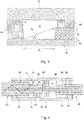
- Fig. 2 is a cross-sectional view schematically showing a cladding mode light removal structure 1 according to an embodiment of the present invention.
- the cladding mode light removal structure 1 has a fiber housing portion 10 in the form of a generally rectangular parallelepiped.
- the fiber housing portion 10 is formed of a material such as aluminum nitride, which has a high thermal conductivity.
- the fiber housing portion 10 is connected to a heat sink (not shown).
- a fusion splice portion 40 in which an input-side optical fiber 20 and an output-side optical fiber 30, which is located at a downstream side of the input-side optical fiber 20, are connected to each other by fusion splice is received within an accommodation space R formed inside of the fiber housing portion 10.
- the input-side optical fiber 20 of this embodiment includes a core 22, a cladding 24 that surrounds the core 22, and a covering 26 that surrounds the cladding 24.
- the cladding 24 is formed of a material having a refractive index lower than the refractive index of the core 22 (e.g., SiO2).
- the covering 26 is formed of a resin having a refractive index lower than the refractive index of the cladding 24 (e.g., low refractive index polymer).
- the output-side optical fiber 30 includes a core 32, a cladding 34 that surround the core 32, and a covering 36 that surrounds the cladding 34.
- the cladding 34 is formed of a material having a refractive index lower than the refractive index of the core 32 (e.g., SiO 2 ).
- the covering 36 is formed of a resin having a refractive index lower than the refractive index of the cladding 34 (e.g., low refractive index polymer).
- the whole circumference of the covering 26 of the input-side optical fiber 20 is removed from a downstream end of the input-side optical fiber 20 by a predetermined length, which forms an input-side cladding exposure portion 28 in which the cladding (input-side cladding) 24 of the input-side optical fiber 20 is exposed. Furthermore, the whole circumference of the covering 36 of the output-side optical fiber 30 is removed from an upstream end of the output-side optical fiber 30 by a predetermined length, which forms an output-side cladding exposure portion 38 in which the cladding (output-side cladding) 34 of the output-side optical fiber 30 is exposed.
- a downstream end of the input-side cladding exposure portion 28 and an upstream end of the output-side cladding exposure portion 38 are faced with each other in the accommodation space R of the fiber housing portion 10 and connected to each other at a fusion splice portion 40 by fusion splice.
- the input-side cladding exposure portion 28, the output-side cladding exposure portion 38, and the fusion splice portion 40 are received in the accommodation space R of the fiber housing portion 10.
- the fiber housing portion 10 serves to protect those components received in the accommodation space R.
- a high refractive index resin 50 formed of a material having a refractive index that is equal to or higher than the refractive index of the cladding 24 of the input-side optical fiber 20 is received in the accommodation space R of the fiber housing portion 10.
- the high refractive index resin 50 covers a downstream end of the covering 26 of the input-side optical fiber 20, a portion of the input-side cladding exposure portion 28 that extends from the covering 26 to the fusion splice portion 40, the fusion splice portion 40, and a portion of the output-side cladding exposure portion 38 extending halfway from the fusion splice portion 40.
- An outer circumferential surface of the high refractive index resin 50 is in contact with the fiber housing portion 10.
- the high refractive index resin 50 serves to remove cladding mode light L C propagating through the cladding 24 of the input-side optical fiber 20 and to fix the input-side optical fiber 20 to the fiber housing portion 10.
- a fixation resin 60 for fixing the output-side optical fiber 30 to the fiber housing portion 10 is received in the accommodation space R of the fiber housing portion 10.
- the fixation resin 60 covers an upstream end of the covering 36 of the output-side optical fiber 30.
- An outer circumferential surface of the fixation resin 60 is in contact with the fiber housing portion 10.
- the same resin as the aforementioned high refractive index resin 50 may be used for the fixation resin 60.
- a space S is formed between the high refractive index resin 50 and the covering 36 of the output-side optical fiber 30 along an axial direction of the output-side optical fiber 30.
- a portion of the output-side cladding exposure portion 38 is exposed to the space S.
- a portion of the output-side cladding exposure portion 38 that is located between the high refractive index resin 50 and the covering 36 of the output-side optical fiber 30 is surrounded by air, which is a medium having a refractive index lower than the refractive index of the cladding 34 of the output-side optical fiber 30.
- the space S serves as a low refractive index portion having a refractive index lower than the refractive index of the cladding 34 of the output-side optical fiber 30.
- the refractive index of the low refractive index portion S may preferably be lower than the refractive index of the high refractive index resin 50.
- the cladding mode light L C that has propagated through the cladding 24 of the input-side optical fiber 20 reaches the input-side cladding exposure portion 28, the cladding mode light L C leaks into the high refractive index resin 50 because the cladding 24 is covered with the high refractive index resin 50.
- a portion of the cladding mode light L C is absorbed by the high refractive index resin 50 and thus converted into heat.
- the generated heat is transmitted to the fiber housing portion 10 and dissipated into the outside of the cladding mode light removal structure from the fiber housing portion 10 through the heat sink.
- the cladding mode light L R that has leaked into the high refractive index resin 50 propagates through the high refractive index resin 50 while a portion of such cladding mode light L R is converted into heat.
- the space S is interposed between the high refractive index resin 50 and the covering 36 of the output-side optical fiber 30 along the axial direction of the output-side optical fiber 30. Therefore, the heat generated in the high refractive index resin 50 is hindered from being transmitted directly to the covering 36 of the output-side optical fiber 30.
- the cladding mode light L C propagating through the cladding 24 of the input-side optical fiber 20 does not completely leak into the high refractive index resin 50 and partially enters the cladding 34 of the output-side optical fiber 30, such cladding mode light that has entered the cladding 34 can be confined in the cladding 34 of the output-side optical fiber 30 because the low refractive index portion S, which is a medium having a refractive index lower than the refractive index of the output-side cladding 34, is located around the output-side cladding exposure portion 38. Therefore, the cladding mode light is inhibited from leaking near the covering 36 of the output-side optical fiber 30. Thus, absorption of the cladding mode light, which would be caused when leaked cladding mode light directly impinges the covering, is inhibited.
- cladding mode light is likely to be generated at the fusion splice portion 40 where two optical fibers 20 and 30 are connected to each other by fusion splice because light propagating through the core 22 of the input-side optical fiber 20 is likely to leak at the fusion splice portion 40.
- the fusion splice portion 40 and a portion of the output-side cladding exposure portion 38 that is located at a downstream side of the fusion splice portion 40 is covered with the high refractive index resin 50. Therefore, most of cladding mode light generated at the fusion splice portion 40 is allowed to leak into the high refractive index resin 50 and converted into heat.
- the cladding mode light L R that has propagated through the high refractive index resin 50 may enter the low refractive index portion S.
- such cladding mode light that has entered the low refractive index portion S should be prevented from directly impinging the covering 36.
- cladding mode light L 0 that enters the low refractive index portion S at the radially innermost portion of a downstream end of the high refractive index resin 50 will reach the radially outermost portion of the covering 36 of the output-side optical fiber 30 as shown in Fig. 3 .
- n H represents the refractive index of the high refractive index resin 50
- n L represents the refractive index of a medium that constitutes the low refractive index portion S (air in this embodiment)
- ⁇ 0 represents the incident angle of the cladding mode light into the high refractive index resin 50.
- NA sin ⁇ 1 . Therefore, the above formula (3) can be modified into the following formulas (4) and (5).
- the cladding 24 of the input-side optical fiber 20 and the cladding 34 of the output-side optical fiber 30 have the same diameter. Nevertheless, the cladding 24 of the input-side optical fiber 20 and the cladding 34 of the output-side optical fiber 30 may have different diameters. Particularly, when the diameter of the cladding 34 of the output-side optical fiber 30 is smaller than the diameter of the cladding 24 of the input-side optical fiber 20 as shown in Fig. 4 , the cladding mode light propagating through the cladding 24 of the input-side optical fiber 20 at the fusion splice portion 40 is more likely to leak into the high refractive index resin 50. Therefore, the cladding mode light can be removed more effectively.
- this configuration can lower the power density of the cladding mode light leaking out of the cladding 24 as compared to the case where the cladding 24 of the input-side optical fiber 20 and the cladding 34 of the output-side optical fiber 30 have the same diameter. Accordingly, the temperature of the high refractive index resin 50 is inhibited from locally increasing.
- the low refractive index portion S is formed by air.
- the low refractive index portion S can be formed by any medium having a refractive index lower than the refractive index of the cladding 34 of the output-side optical fiber 30.
- the low refractive index portion S may be formed by a resin having a refractive index lower than the refractive index of the cladding 34 of the output-side optical fiber 30.
- the thermal conductivity of the resin of the low refractive index portion S may preferably be lower than the thermal conductivity of the high refractive index resin 50 in order to inhibit heat generated in the high refractive index resin 50 from transmitting to the covering 36 to the output-side optical fiber 30.
- the entire input-side cladding exposure portion 28 is covered with the high refractive index resin 50. Only a portion of the input-side cladding exposure portion 28 may be covered with the high refractive index resin 50. In such a case, a portion of the input-side cladding exposure portion 28, the fusion splice portion 40, and a portion of the output-side cladding exposure portion 38 are covered with the high refractive index resin 50.
- each of the input-side optical fiber 20 and the output-side optical fiber 30 is formed by a single-cladding fiber.
- the present invention can be applied to cases where the input-side optical fiber 20 or the output-side optical fiber 30 has two or more claddings.
- the high refractive index resin 50 employs a material having a refractive index that is equal to or higher than the refractive index of the outermost cladding layer of the input-side optical fiber 20.
- the low refractive index portion S is formed by a medium having a refractive index lower than the refractive index of the outermost cladding layer of the output-side optical fiber 30.
- cladding mode light removal structure can be applied to any portion where cladding mode light needs to be removed in a laser apparatus such as a fiber laser.
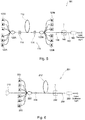
- Fig. 5 is a schematic view showing an example of a fiber laser to which a cladding mode light removal structure according to the present invention is applicable.
- a fiber laser 101 illustrated in Fig. 5 includes an optical cavity 110, a plurality of forward pumping light sources 120A operable to introduce pumping light to the optical cavity 110 from a front side of the optical cavity 110, a forward in-line combiner 122A connected to those forward pumping light sources 120A, a plurality of backward pumping light sources 120B operable to introduce pumping light to the optical cavity 110 from a back side of the optical cavity 110, and a backward in-line combiner 122B connected to those backward pumping light sources 120B.
- the optical cavity 110 includes an amplification optical fiber 112 having a core into which rare earth ions such as yttrium (Yb) or erbium (Er) have been doped, a high reflectivity fiber Bragg grating (HR-FBG) 114 connected to the amplification optical fiber 112 and the forward in-line combiner 122A, and a low reflectivity fiber Bragg grating (Output Coupler Fiber Bragg Grating (OC-FBG)) 116 connected to the amplification optical fiber 112 and the backward in-line combiner 122B.
- the amplification optical fiber 112 is formed of a double cladding fiber having an inner cladding formed around a core and an outer cladding formed around the inner cladding.
- the fiber laser 101 has a first delivery fiber 130 extending from the backward in-line combiner 122B and a second delivery fiber 150 connected to the first delivery fiber 130 at a fusion splice portion 140 by fusion splice.
- a laser emission portion 160 is provided at a downstream end of the second delivery fiber 150 for emitting laser oscillation light from the amplification optical fiber 112, for example, toward a workpiece.
- high-power multi-mode semiconductor lasers having a wavelength of 915 nm may be used as the forward pumping light sources 120A and the backward pumping light sources 120B.
- the forward in-line combiner 122A and the backward in-line combiner 122B are operable to combine pumping light beams outputted from the forward pumping light source 120A and the backward pumping light source 120B, respectively, and introduce the combined pumping light to the interior of the aforementioned inner cladding of the amplification optical fiber 112.
- the pumping light propagates within the inner cladding of the amplification optical fiber 112.
- the HR-FBG 114 is formed by periodically varying the refractive index of an optical fiber.
- the HR-FBG 114 reflects light having a certain wavelength range at a reflectivity near 100 %.
- the OC-FBG 116 is formed by periodically varying the refractive index of an optical fiber.
- the OC-FBG 116 allows a portion of light having the wavelength range that is to be reflected by the HR-FBG 114 (e.g., 10 %) to pass therethrough and reflects the rest of the light.
- the HR-FBG 114, the amplification optical fiber 112, and the OC-FBG 116 form the optical cavity 110, which recursively amplifies light having a specific wavelength range between the HR-FBG 114 and the OC-FBG 116 to cause laser oscillation.
- the aforementioned cladding mode light removal structure 1 can be applied to, for example, the fusion splice portion 140 where the first delivery fiber 130 and the second delivery fiber 150 are connected to each other by fusion splice.
- cladding mode light such as pumping light that has not been absorbed by the amplification optical fiber 112 and the laser light that has leaked from the core of the amplification optical fiber 112 can effectively be removed.
- the cladding mode light removal structure 1 may be provided not only at the fusion splice portion 140, but also at any location where cladding mode light needs to be removed.
- Fig. 5 illustrates an example a bidirectional pumping fiber laser apparatus where the pumping light sources 120A or 120B and the combiner 122A or 122B are provided for each of the HR-FBG 114 and the OC-FBG 116.
- pumping light sources and a combiner may be provided for one of the HR-FBG 114 and the OC-FBG 116.
- mirrors may be used as reflection means for causing laser oscillation in the optical cavity 110.
- FIG. 6 is a schematic view showing another example of a fiber laser to which a cladding mode light removal structure according to the present invention can be applied.
- a fiber laser 201 illustrated in Fig. 6 includes a signal light generator 210 operable to generate signal light, a plurality of pumping light sources 220 operable to generate pumping light, an optical coupler 222 operable to combine the signal light from the signal light generator 210, an amplification optical fiber 212 having an end connected to an output end 224 of the optical coupler 222, and a delivery fiber 250 connected to the amplification optical fiber 212 at a fusion splice portion 240 by fusion splice.
- a laser emission portion (isolator) 260 is provided at a downstream end of the delivery fiber 250 for emitting laser oscillation light from the amplification optical fiber 212, for example, toward a workpiece.
- Fig. 7 is a cross-sectional view schematically showing the amplification optical fiber 212.
- the amplification optical fiber 212 is formed of a double cladding fiber having a core 214 through which the signal light generated by the signal light generator 210 propagates, an inner cladding 216 formed around the core 214, and an outer cladding 218 formed around the inner cladding 216.
- the core 214 is formed of SiO 2 into which a rare earth element such as Yb has been doped.
- the core 214 serves as a signal light waveguide through which the signal light propagates.
- the inner cladding 216 is formed of a material having a refractive index lower than the refractive index of the core 214 (e.g., SiO 2 ).
- the outer cladding 218 is formed of a resin having a refractive index lower than the refractive index of the inner cladding 216 (e.g., a low refractive index polymer).
- the inner cladding 216 serves as a pumping light waveguide through which the pumping light propagates.
- the signal light from the signal light generator 210 propagates within the core 214 of the amplification optical fiber 212.
- the pumping light from the pumping light sources 220 propagates within the inner cladding 216 and the core 214 of the amplification optical fiber 212.
- the rare earth ions that have doped into the core 214 absorb the pumping light so that those ions are excited so as to amplify the signal light propagating through the core 214 by stimulated emission.
- the aforementioned cladding mode light removal structure 1 can be applied to, for example, the fusion splice portion 240 where the amplification optical fiber 212 and the delivery fiber 250 are connected to each other by fusion splice.
- cladding mode light such as pumping light that has not been absorbed by the amplification optical fiber 212 and the laser light that has leaked from the core of the amplification optical fiber 212 can effectively be removed.
- the cladding mode light removal structure 1 may be provided not only at the fusion splice portion 240, but also at any location where cladding mode light needs to be removed.
- the present invention is suitably used for a structure for removing cladding mode light that propagates through a cladding of an optical fiber in a laser apparatus such as a fiber laser.
Landscapes
- Physics & Mathematics (AREA)
- Electromagnetism (AREA)
- Engineering & Computer Science (AREA)
- Plasma & Fusion (AREA)
- Optics & Photonics (AREA)
- General Physics & Mathematics (AREA)
- Lasers (AREA)
- Optical Fibers, Optical Fiber Cores, And Optical Fiber Bundles (AREA)
- Mechanical Coupling Of Light Guides (AREA)
- Optical Couplings Of Light Guides (AREA)
Abstract
Description
- The present invention relates to a cladding mode light removal structure, and more particularly to a structure for removing cladding mode light that propagates through a cladding of an optical fiber in a laser apparatus such as a fiber laser.
- In a laser apparatus such as a fiber laser, a portion of light propagating through a core of an optical fiber may leak into a cladding due to misalignment of optical axes at a fusion splice portion of optical fibers or microbend of an optical fiber and thus propagate as cladding mode light through the cladding. Such cladding mode light causes deterioration of the quality of a laser beam outputted from a laser apparatus. Therefore, it is desirable to remove cladding mode light before a laser beam is outputted from the laser apparatus. Increase of an output of a laser apparatus such as a fiber laser enhances the power of such cladding mode light. Accordingly, demand for removing cladding mode light has risen even more.
- In order to remove such cladding mode light, there has been proposed a method of removing a portion of a covering of an optical fiber so as to expose a cladding and then covering the exposed cladding with a resin having a refractive index higher than that of the cladding (see, e.g., Patent Literature 1).
Fig. 1 is a cross-sectional view schematically showing such a conventional cladding mode light removal structure. As shown inFig. 1 , in this cladding modelight removal structure 501, a portion of a covering 520 of anoptical fiber 510 is removed so as to expose acladding 530. The exposed portion of thecladding 530 is covered with aresin 540 having a refractive index higher than that of thecladding 530. - With such a structure, as the refractive index of the
resin 540, which surrounds thecladding 530, is higher than the refractive index of the cladding 530, cladding mode light LC propagating through the cladding 530 leaks into theresin 540. A portion of the cladding mode light LC is absorbed into theresin 540 and thus converted into heat. The generated heat is dissipated from ahousing 550 into an outside of thehousing 550 through a heat sink (not shown) connected to thehousing 550. In this manner, unnecessary cladding mode light Lc can be removed by conversion of the cladding mode light LC into heat, which is in turn dissipated into an outside of thehousing 550. - The cladding mode light LR, which has leaked into the
resin 540, propagates through theresin 540 while a portion of the cladding mode light LR is converted into heat. In the structure illustrated inFig. 1 , a portion of theresin 540 that surrounds thecladding 530 is held in contact with a covering 520A located on a downstream side of the structure. Therefore, a portion of the cladding mode light LR, which has leaked into theresin 540, may impinge the downstream covering 520A. In such a case, the cladding mode light LR is absorbed into the covering 520A, which generates heat and rises its temperature. Furthermore, even if the cladding mode light LR does not directly impinge the covering 520A, the heat generated in theresin 540 that has absorbed the cladding mode light LR may be transmitted through theresin 540 to the covering 520A, so that the temperature of thecovering 520A increases. Such increased temperature of the covering 520A may cause firing of the covering 520A or deterioration of the optical characteristics of theoptical fiber 510. - Patent Literature 1:
JP 4954737 B - The present invention has been made in view of the above drawbacks in the prior art. It is, therefore, an object of the present invention to provide a cladding mode light removal structure that can suppress heat generation at a covering of an optical fiber and effectively remove cladding mode light and a laser apparatus including such a cladding mode light removal structure.
- According to a first aspect of the present invention, there is provided a cladding mode light removal structure that can suppress heat generation at a covering of an optical fiber and effectively remove cladding mode light. This cladding mode light removal structure is used for removing cladding mode light that propagates through a cladding of an optical fiber. The cladding mode light removal structure includes an input-side cladding exposure portion where a covering is removed at an end of an input-side optical fiber so that an input-side cladding of the input-side optical fiber is exposed, an output-side cladding exposure portion where a covering is removed at an end of an output-side optical fiber so that an output-side cladding of the output-side optical fiber is exposed, a fusion splice portion at which the input-side cladding exposure portion and the output-side cladding exposure portion are connected to each other by fusion splice, and a fiber housing portion in which an accommodation space is formed to receive the input-side cladding exposure portion, the output-side cladding exposure portion, and the fusion splice portion. The cladding mode light removal structure further includes a high refractive index resin having a refractive index that is equal to or higher than a refractive index of the input-side cladding exposed at the input-side cladding exposure portion. The high refractive index resin is provided within the accommodation space of the fiber housing portion so as to surround a downstream end of the covering of the input-side optical fiber, an entire portion of the input-side cladding that is exposed at the input-side cladding exposure portion, the fusion splice portion, and a portion of the output-side cladding exposed at the output-side cladding exposure portion. The cladding mode light removal structure further includes a low refractive index portion of a medium having a refractive index lower than a refractive index of the output-side cladding of the output-side cladding exposure portion. The low refractive index portion is located around the output-side cladding exposure portion between the high refractive index resin and the covering of the output-side optical fiber along an axial direction of the output-side optical fiber.
- The term "cladding" used in connection with the present invention refers to the outermost cladding layer if an optical fiber has a plurality of cladding layers. Specifically, the term "input-side cladding" refers to the outmost cladding layer of an input-side optical fiber if the input-side optical fiber has a plurality of cladding layers. The term "output-side cladding" refers to the outermost cladding layer of an output-side optical fiber if the output-side optical fiber has a plurality of cladding layers.
- With this configuration, when cladding mode light that has propagated through the input-side cladding of the input-side optical fiber reaches the input-side cladding exposure portion, the cladding mode light leaks into the high refractive index resin because the entire input-side cladding is covered with the high refractive index resin. Thus, a portion of the cladding mode light is absorbed by the high refractive index resin and thus converted into heat. The generated heat can be dissipated into the outside of the cladding mode light removal structure through the fiber housing portion. Accordingly, the cladding mode light can effectively be removed. At that time, the low refractive index portion is interposed between the high refractive index resin and the covering of the output-side optical fiber along the axial direction of the output-side optical fiber. Therefore, the heat generated in the high refractive index resin is hindered from being transmitted directly to the covering of the output-side optical fiber.
- Furthermore, even if the cladding mode light propagating through the cladding of the input-side optical fiber does not completely leak into the high refractive index resin and partially enters the cladding of the output-side optical fiber, such cladding mode light that has entered the cladding can be confined in the cladding of the output-side optical fiber because the low refractive index portion, which is a medium having a refractive index lower than the refractive index of the output-side cladding, is located around the output-side cladding exposure portion. Therefore, the cladding mode light is inhibited from leaking near the covering of the output-side optical fiber. Thus, absorption of the cladding mode light, which would be caused when leaked cladding mode light directly enters the covering, is inhibited.
- The length x of the low refractive index portion along the axial direction of the output-side optical fiber may preferably satisfy

- Furthermore, the input-side cladding may preferably have a diameter greater than a diameter of the output-side cladding. When the diameter of the input-side cladding is greater than the diameter of the output-side cladding, cladding mode light propagating through the cladding of the input-side optical fiber is likely to leak into the high refractive index resin at the fusion splice portion. Therefore, the cladding mode light can be removed more effectively. Furthermore, this configuration can lower the power density of the cladding mode light leaking out of the cladding as compared to the case where the cladding of the input-side optical fiber and the cladding of the output-side optical fiber have the same diameter. Accordingly, the temperature of the high refractive index resin is inhibited from locally increasing.
- Furthermore, the medium of the low refractive index portion may comprise air. When the low refractive index portion is formed by air, cladding mode light that has not leaked into the high refractive index resin and entered the cladding of the output-side optical fiber can effectively be confined in the cladding of the output-side optical fiber. Therefore, cladding mode light is effectively inhibited from leaking near the covering of the output-side optical fiber.
- According to a second aspect of the present invention, there is provided a laser apparatus that can suppress heat generation at a covering of an optical fiber and effectively remove cladding mode light. This laser apparatus includes an optical fiber amplifier including a pumping light source operable to output pumping light and an amplification optical fiber including a core into which a rare earth element to be excited by the pumping light from the pumping light source has been doped, and the aforementioned cladding mode light removal structure. In the cladding mode light removal structure, the input-side optical fiber corresponds to the amplification optical fiber of the optical fiber amplifier or an optical fiber located on a downstream side of the amplification optical fiber.
- According to the present invention, when cladding mode light that has propagated through the input-side cladding of the input-side optical fiber reaches the input-side cladding exposure portion, the cladding mode light leaks into the high refractive index resin because the entire input-side cladding is covered with the high refractive index resin. Thus, a portion of the cladding mode light is absorbed by the high refractive index resin and thus converted into heat. The generated heat can be dissipated into the outside of the cladding mode light removal structure through the fiber housing portion. At that time, the low refractive index portion is interposed between the high refractive index resin and the covering of the output-side optical fiber along the axial direction of the output-side optical fiber. Therefore, the heat generated in the high refractive index resin is hindered from being transmitted directly to the covering of the output-side optical fiber.
- Furthermore, even if the cladding mode light propagating through the cladding of the input-side optical fiber does not completely leak into the high refractive index resin and partially enters the cladding of the output-side optical fiber, such cladding mode light that has entered the cladding can be confined in the cladding of the output-side optical fiber because the low refractive index portion, which is a medium having a refractive index lower than the refractive index of the output-side cladding, is located around the output-side cladding exposure portion. Therefore, the cladding mode light is inhibited from leaking near the covering of the output-side optical fiber. Thus, absorption of the cladding mode light, which would be caused when leaked cladding mode light directly enters the covering, is inhibited.
-
-
Fig. 1 is a cross-sectional view schematically showing a conventional cladding mode light removal structure. -
Fig. 2 is cross-sectional view schematically showing a cladding mode light removal structure according to an embodiment of the present invention. -
Fig. 3 is a cross-sectional view schematically showing a portion of the cladding mode light removal structure illustrated inFig. 2 . -
Fig. 4 is a cross-sectional view schematically showing a cladding mode light removal structure according to another embodiment of the present invention. -
Fig. 5 is a schematic diagram showing an example of a fiber laser to which a cladding mode light removal structure according to the present invention can be applied. -
Fig. 6 is a schematic diagram showing another example of a fiber laser to which a cladding mode light removal structure according to the present invention can be applied. -
Fig. 7 is a cross-sectional view schematically showing an amplification optical fiber in the fiber laser illustrated inFig. 6 . - Embodiments of a cladding mode light removal structure and a laser apparatus according to the present invention will be described in detail below with reference to
Figs. 2 to 7 . InFigs. 2 to 7 , the same or corresponding components are denoted by the same or corresponding reference numerals and will not be described below repetitively. Furthermore, inFigs. 2 to 7 , the scales or dimensions of components may be exaggerated, or some components may be omitted. -
Fig. 2 is a cross-sectional view schematically showing a cladding modelight removal structure 1 according to an embodiment of the present invention. As shown inFig. 2 , the cladding modelight removal structure 1 has afiber housing portion 10 in the form of a generally rectangular parallelepiped. For example, thefiber housing portion 10 is formed of a material such as aluminum nitride, which has a high thermal conductivity. Thefiber housing portion 10 is connected to a heat sink (not shown). Afusion splice portion 40 in which an input-sideoptical fiber 20 and an output-sideoptical fiber 30, which is located at a downstream side of the input-sideoptical fiber 20, are connected to each other by fusion splice is received within an accommodation space R formed inside of thefiber housing portion 10. - The input-side
optical fiber 20 of this embodiment includes a core 22, acladding 24 that surrounds thecore 22, and a covering 26 that surrounds thecladding 24. Thecladding 24 is formed of a material having a refractive index lower than the refractive index of the core 22 (e.g., SiO2). The covering 26 is formed of a resin having a refractive index lower than the refractive index of the cladding 24 (e.g., low refractive index polymer). Similarly, the output-sideoptical fiber 30 includes a core 32, acladding 34 that surround thecore 32, and a covering 36 that surrounds thecladding 34. Thecladding 34 is formed of a material having a refractive index lower than the refractive index of the core 32 (e.g., SiO2). The covering 36 is formed of a resin having a refractive index lower than the refractive index of the cladding 34 (e.g., low refractive index polymer). - The whole circumference of the covering 26 of the input-side
optical fiber 20 is removed from a downstream end of the input-sideoptical fiber 20 by a predetermined length, which forms an input-sidecladding exposure portion 28 in which the cladding (input-side cladding) 24 of the input-sideoptical fiber 20 is exposed. Furthermore, the whole circumference of the covering 36 of the output-sideoptical fiber 30 is removed from an upstream end of the output-sideoptical fiber 30 by a predetermined length, which forms an output-sidecladding exposure portion 38 in which the cladding (output-side cladding) 34 of the output-sideoptical fiber 30 is exposed. A downstream end of the input-sidecladding exposure portion 28 and an upstream end of the output-sidecladding exposure portion 38 are faced with each other in the accommodation space R of thefiber housing portion 10 and connected to each other at afusion splice portion 40 by fusion splice. In this manner, the input-sidecladding exposure portion 28, the output-sidecladding exposure portion 38, and thefusion splice portion 40 are received in the accommodation space R of thefiber housing portion 10. Thus, thefiber housing portion 10 serves to protect those components received in the accommodation space R. - As shown in
Fig. 2 , a highrefractive index resin 50 formed of a material having a refractive index that is equal to or higher than the refractive index of thecladding 24 of the input-sideoptical fiber 20 is received in the accommodation space R of thefiber housing portion 10. The highrefractive index resin 50 covers a downstream end of the covering 26 of the input-sideoptical fiber 20, a portion of the input-sidecladding exposure portion 28 that extends from the covering 26 to thefusion splice portion 40, thefusion splice portion 40, and a portion of the output-sidecladding exposure portion 38 extending halfway from thefusion splice portion 40. An outer circumferential surface of the highrefractive index resin 50 is in contact with thefiber housing portion 10. The highrefractive index resin 50 serves to remove cladding mode light LC propagating through thecladding 24 of the input-sideoptical fiber 20 and to fix the input-sideoptical fiber 20 to thefiber housing portion 10. - Furthermore, a
fixation resin 60 for fixing the output-sideoptical fiber 30 to thefiber housing portion 10 is received in the accommodation space R of thefiber housing portion 10. Thefixation resin 60 covers an upstream end of the covering 36 of the output-sideoptical fiber 30. An outer circumferential surface of thefixation resin 60 is in contact with thefiber housing portion 10. The same resin as the aforementioned highrefractive index resin 50 may be used for thefixation resin 60. - As shown in
Fig. 2 , a space S is formed between the highrefractive index resin 50 and the covering 36 of the output-sideoptical fiber 30 along an axial direction of the output-sideoptical fiber 30. A portion of the output-sidecladding exposure portion 38 is exposed to the space S. In other words, a portion of the output-sidecladding exposure portion 38 that is located between the highrefractive index resin 50 and the covering 36 of the output-sideoptical fiber 30 is surrounded by air, which is a medium having a refractive index lower than the refractive index of thecladding 34 of the output-sideoptical fiber 30. Thus, the space S serves as a low refractive index portion having a refractive index lower than the refractive index of thecladding 34 of the output-sideoptical fiber 30. The refractive index of the low refractive index portion S may preferably be lower than the refractive index of the highrefractive index resin 50. - With the aforementioned configuration, when the cladding mode light LC that has propagated through the
cladding 24 of the input-sideoptical fiber 20 reaches the input-sidecladding exposure portion 28, the cladding mode light LC leaks into the highrefractive index resin 50 because thecladding 24 is covered with the highrefractive index resin 50. Thus, a portion of the cladding mode light LC is absorbed by the highrefractive index resin 50 and thus converted into heat. The generated heat is transmitted to thefiber housing portion 10 and dissipated into the outside of the cladding mode light removal structure from thefiber housing portion 10 through the heat sink. - At that time, the cladding mode light LR that has leaked into the high
refractive index resin 50 propagates through the highrefractive index resin 50 while a portion of such cladding mode light LR is converted into heat. As described above, the space S is interposed between the highrefractive index resin 50 and the covering 36 of the output-sideoptical fiber 30 along the axial direction of the output-sideoptical fiber 30. Therefore, the heat generated in the highrefractive index resin 50 is hindered from being transmitted directly to the covering 36 of the output-sideoptical fiber 30. - Furthermore, even if the cladding mode light LC propagating through the
cladding 24 of the input-sideoptical fiber 20 does not completely leak into the highrefractive index resin 50 and partially enters thecladding 34 of the output-sideoptical fiber 30, such cladding mode light that has entered thecladding 34 can be confined in thecladding 34 of the output-sideoptical fiber 30 because the low refractive index portion S, which is a medium having a refractive index lower than the refractive index of the output-side cladding 34, is located around the output-sidecladding exposure portion 38. Therefore, the cladding mode light is inhibited from leaking near the covering 36 of the output-sideoptical fiber 30. Thus, absorption of the cladding mode light, which would be caused when leaked cladding mode light directly impinges the covering, is inhibited. - Furthermore, cladding mode light is likely to be generated at the
fusion splice portion 40 where twooptical fibers core 22 of the input-sideoptical fiber 20 is likely to leak at thefusion splice portion 40. As described above, however, thefusion splice portion 40 and a portion of the output-sidecladding exposure portion 38 that is located at a downstream side of thefusion splice portion 40 is covered with the highrefractive index resin 50. Therefore, most of cladding mode light generated at thefusion splice portion 40 is allowed to leak into the highrefractive index resin 50 and converted into heat. - Meanwhile, the cladding mode light LR that has propagated through the high
refractive index resin 50 may enter the low refractive index portion S. In order to inhibit heat generation at the covering 36 of the output-sideoptical fiber 30 more effectively, such cladding mode light that has entered the low refractive index portion S should be prevented from directly impinging thecovering 36. To address this issue, it is assumed that cladding mode light L0 that enters the low refractive index portion S at the radially innermost portion of a downstream end of the highrefractive index resin 50 will reach the radially outermost portion of the covering 36 of the output-sideoptical fiber 30 as shown inFig. 3 . - The following formula (1) is found where x 0 represents the length of the output-side
cladding exposure portion 38 of the low refractive index portion S along the axis direction, θ 0 represents an outgoing angle of the cladding mode light at the low refractive index portion S, D 1 represents the diameter of the covering 36, and D 2 represents the diameter of the output-side cladding 34.
- This formula is modified into the following formula (2).

- The following formula (3) is derived from the Snell's law.

refractive index resin 50, nL represents the refractive index of a medium that constitutes the low refractive index portion S (air in this embodiment), and θ 0 represents the incident angle of the cladding mode light into the highrefractive index resin 50. - The numerical aperture NA of the cladding mode light in the high
refractive index resin 50 is represented by NA = sin θ 1. Therefore, the above formula (3) can be modified into the following formulas (4) and (5).

- The following formula (6) is derived from the above formulas (2) and (5).

- If the distance x from the covering 36 of the output-side
optical fiber 30 to the downstream end of the highrefractive index resin 50 along the axial direction of the output-side optical fiber 30 (Fig. 2 ) is greater than x 0 represented by the above formula (5), then cladding mode light that has entered the low refractive index portion S will not directly impinge thecovering 36. In other words, the cladding mode light does not directly impinge the covering 36 if the following relationship is met.
- Assuming that the refractive index of the air is 1.00, when the numerical aperture NA of the cladding mode light in the high
refractive index resin 50 was varied in a case where a resin having a refractive index of 1.54 was used as the highrefractive index resin 50, x 0 (unit: µm) was calculated as shown in Table 1 for the following three output-sideoptical fibers 30. - (1) The covering 36 has a diameter D 1 = 250 µm, and the
cladding 34 has a diameter D 2 = 125 µm - (2) The covering 36 has a diameter D 1 = 200 µm, and the
cladding 34 has a diameter D 2 = 90 µm - (3) The covering 36 has a diameter D 1 = 320 µm, and the
cladding 34 has a diameter D 2 = 280 µm - In the above embodiment, the
cladding 24 of the input-sideoptical fiber 20 and thecladding 34 of the output-sideoptical fiber 30 have the same diameter. Nevertheless, thecladding 24 of the input-sideoptical fiber 20 and thecladding 34 of the output-sideoptical fiber 30 may have different diameters. Particularly, when the diameter of thecladding 34 of the output-sideoptical fiber 30 is smaller than the diameter of thecladding 24 of the input-sideoptical fiber 20 as shown inFig. 4 , the cladding mode light propagating through thecladding 24 of the input-sideoptical fiber 20 at thefusion splice portion 40 is more likely to leak into the highrefractive index resin 50. Therefore, the cladding mode light can be removed more effectively. Furthermore, this configuration can lower the power density of the cladding mode light leaking out of thecladding 24 as compared to the case where thecladding 24 of the input-sideoptical fiber 20 and thecladding 34 of the output-sideoptical fiber 30 have the same diameter. Accordingly, the temperature of the highrefractive index resin 50 is inhibited from locally increasing. - In the above embodiment, the low refractive index portion S is formed by air. However, the low refractive index portion S can be formed by any medium having a refractive index lower than the refractive index of the
cladding 34 of the output-sideoptical fiber 30. For example, the low refractive index portion S may be formed by a resin having a refractive index lower than the refractive index of thecladding 34 of the output-sideoptical fiber 30. In this case, the thermal conductivity of the resin of the low refractive index portion S may preferably be lower than the thermal conductivity of the highrefractive index resin 50 in order to inhibit heat generated in the highrefractive index resin 50 from transmitting to the covering 36 to the output-sideoptical fiber 30. - In the aforementioned embodiment, the entire input-side
cladding exposure portion 28 is covered with the highrefractive index resin 50. Only a portion of the input-sidecladding exposure portion 28 may be covered with the highrefractive index resin 50. In such a case, a portion of the input-sidecladding exposure portion 28, thefusion splice portion 40, and a portion of the output-sidecladding exposure portion 38 are covered with the highrefractive index resin 50. - Furthermore, in the aforementioned embodiment, each of the input-side
optical fiber 20 and the output-sideoptical fiber 30 is formed by a single-cladding fiber. As a matter of course, however, the present invention can be applied to cases where the input-sideoptical fiber 20 or the output-sideoptical fiber 30 has two or more claddings. When the input-sideoptical fiber 20 has a plurality of cladding layers, the highrefractive index resin 50 employs a material having a refractive index that is equal to or higher than the refractive index of the outermost cladding layer of the input-sideoptical fiber 20. Furthermore, when the output-sideoptical fiber 30 has a plurality of cladding layers, the low refractive index portion S is formed by a medium having a refractive index lower than the refractive index of the outermost cladding layer of the output-sideoptical fiber 30. - The aforementioned cladding mode light removal structure can be applied to any portion where cladding mode light needs to be removed in a laser apparatus such as a fiber laser.
Fig. 5 is a schematic view showing an example of a fiber laser to which a cladding mode light removal structure according to the present invention is applicable. - A
fiber laser 101 illustrated inFig. 5 includes anoptical cavity 110, a plurality of forward pumpinglight sources 120A operable to introduce pumping light to theoptical cavity 110 from a front side of theoptical cavity 110, a forward in-line combiner 122A connected to those forward pumpinglight sources 120A, a plurality of backward pumpinglight sources 120B operable to introduce pumping light to theoptical cavity 110 from a back side of theoptical cavity 110, and a backward in-line combiner 122B connected to those backward pumpinglight sources 120B. Theoptical cavity 110 includes an amplificationoptical fiber 112 having a core into which rare earth ions such as yttrium (Yb) or erbium (Er) have been doped, a high reflectivity fiber Bragg grating (HR-FBG) 114 connected to the amplificationoptical fiber 112 and the forward in-line combiner 122A, and a low reflectivity fiber Bragg grating (Output Coupler Fiber Bragg Grating (OC-FBG)) 116 connected to the amplificationoptical fiber 112 and the backward in-line combiner 122B. For example, the amplificationoptical fiber 112 is formed of a double cladding fiber having an inner cladding formed around a core and an outer cladding formed around the inner cladding. - Furthermore, as shown in
Fig. 5 , thefiber laser 101 has afirst delivery fiber 130 extending from the backward in-line combiner 122B and asecond delivery fiber 150 connected to thefirst delivery fiber 130 at afusion splice portion 140 by fusion splice. Alaser emission portion 160 is provided at a downstream end of thesecond delivery fiber 150 for emitting laser oscillation light from the amplificationoptical fiber 112, for example, toward a workpiece. - For example, high-power multi-mode semiconductor lasers (LD) having a wavelength of 915 nm may be used as the forward
pumping light sources 120A and the backward pumpinglight sources 120B. The forward in-line combiner 122A and the backward in-line combiner 122B are operable to combine pumping light beams outputted from the forward pumpinglight source 120A and the backwardpumping light source 120B, respectively, and introduce the combined pumping light to the interior of the aforementioned inner cladding of the amplificationoptical fiber 112. Thus, the pumping light propagates within the inner cladding of the amplificationoptical fiber 112. - The HR-
FBG 114 is formed by periodically varying the refractive index of an optical fiber. The HR-FBG 114 reflects light having a certain wavelength range at a reflectivity near 100 %. As with the HR-FBG 114, the OC-FBG 116 is formed by periodically varying the refractive index of an optical fiber. The OC-FBG 116 allows a portion of light having the wavelength range that is to be reflected by the HR-FBG 114 (e.g., 10 %) to pass therethrough and reflects the rest of the light. Thus, the HR-FBG 114, the amplificationoptical fiber 112, and the OC-FBG 116 form theoptical cavity 110, which recursively amplifies light having a specific wavelength range between the HR-FBG 114 and the OC-FBG 116 to cause laser oscillation. - In the
fiber laser 101 thus configured, the aforementioned cladding modelight removal structure 1 can be applied to, for example, thefusion splice portion 140 where thefirst delivery fiber 130 and thesecond delivery fiber 150 are connected to each other by fusion splice. Thus, when the cladding modelight removal structure 1 is applied to thefusion splice portion 140, cladding mode light such as pumping light that has not been absorbed by the amplificationoptical fiber 112 and the laser light that has leaked from the core of the amplificationoptical fiber 112 can effectively be removed. As a matter of course, the cladding modelight removal structure 1 may be provided not only at thefusion splice portion 140, but also at any location where cladding mode light needs to be removed. -
Fig. 5 illustrates an example a bidirectional pumping fiber laser apparatus where the pumpinglight sources combiner FBG 114 and the OC-FBG 116. However, pumping light sources and a combiner may be provided for one of the HR-FBG 114 and the OC-FBG 116. Furthermore, instead of FBGs, mirrors may be used as reflection means for causing laser oscillation in theoptical cavity 110. -
Fig. 6 is a schematic view showing another example of a fiber laser to which a cladding mode light removal structure according to the present invention can be applied. Afiber laser 201 illustrated inFig. 6 includes asignal light generator 210 operable to generate signal light, a plurality of pumpinglight sources 220 operable to generate pumping light, anoptical coupler 222 operable to combine the signal light from thesignal light generator 210, an amplificationoptical fiber 212 having an end connected to anoutput end 224 of theoptical coupler 222, and adelivery fiber 250 connected to the amplificationoptical fiber 212 at afusion splice portion 240 by fusion splice. A laser emission portion (isolator) 260 is provided at a downstream end of thedelivery fiber 250 for emitting laser oscillation light from the amplificationoptical fiber 212, for example, toward a workpiece. -
Fig. 7 is a cross-sectional view schematically showing the amplificationoptical fiber 212. As shown inFig. 7 , the amplificationoptical fiber 212 is formed of a double cladding fiber having a core 214 through which the signal light generated by thesignal light generator 210 propagates, aninner cladding 216 formed around thecore 214, and anouter cladding 218 formed around theinner cladding 216. For example, thecore 214 is formed of SiO2 into which a rare earth element such as Yb has been doped. Thecore 214 serves as a signal light waveguide through which the signal light propagates. Theinner cladding 216 is formed of a material having a refractive index lower than the refractive index of the core 214 (e.g., SiO2). Theouter cladding 218 is formed of a resin having a refractive index lower than the refractive index of the inner cladding 216 (e.g., a low refractive index polymer). Thus, theinner cladding 216 serves as a pumping light waveguide through which the pumping light propagates. - The signal light from the
signal light generator 210 propagates within thecore 214 of the amplificationoptical fiber 212. The pumping light from the pumpinglight sources 220 propagates within theinner cladding 216 and thecore 214 of the amplificationoptical fiber 212. When the pumping light propagates through thecore 214, the rare earth ions that have doped into thecore 214 absorb the pumping light so that those ions are excited so as to amplify the signal light propagating through thecore 214 by stimulated emission. - In the
fiber laser 201 thus configured, the aforementioned cladding modelight removal structure 1 can be applied to, for example, thefusion splice portion 240 where the amplificationoptical fiber 212 and thedelivery fiber 250 are connected to each other by fusion splice. Thus, when the cladding modelight removal structure 1 is applied to thefusion splice portion 240, cladding mode light such as pumping light that has not been absorbed by the amplificationoptical fiber 212 and the laser light that has leaked from the core of the amplificationoptical fiber 212 can effectively be removed. As a matter of course, the cladding modelight removal structure 1 may be provided not only at thefusion splice portion 240, but also at any location where cladding mode light needs to be removed. - Although some preferred embodiments of the present invention have been described, the present invention is not limited to the aforementioned embodiments. It should be understood that various different forms may be applied to the present invention within the technical idea thereof.
- The present invention is suitably used for a structure for removing cladding mode light that propagates through a cladding of an optical fiber in a laser apparatus such as a fiber laser.
-
- 1
- Cladding mode light removal structure
- 10
- Fiber housing portion
- 20
- Input-side optical fiber
- 22
- Core
- 24
- Input-side cladding
- 26
- Covering
- 28
- Input-side cladding exposure portion
- 30
- Output-side optical fiber
- 32
- Core
- 34
- Output-side cladding
- 36
- Covering
- 38
- Output-side cladding exposure portion
- 40
- Fusion splice portion
- 50
- High refractive index resin
- 60
- Fixation resin
- 101
- Fiber laser
- 110
- Optical cavity
- 112
- Amplification optical fiber
- 114
- HR-FBG
- 116
- OC-FBG
- 120A, 120B
- Pumping light source
- 122A, 122B
- In-line combiner
- 130, 150
- Delivery fiber
- 140
- Fusion splice portion
- 160
- Laser emission portion
- 201
- Fiber laser
- 210
- Signal light generator
- 212
- Amplification optical fiber
- 214
- Core
- 216
- Inner cladding
- 218
- Outer cladding
- 220
- Pumping light source
- 222
- Optical coupler
- 224
- Output end
- 240
- Fusion splice portion
- 250
- Delivery fiber
- 290
- Output-side cladding exposure portion
- R
- Accommodation space
- S
- Low refractive index portion
| NA | 0.01 | 0.05 | 0.10 | 0.15 | 0.20 | 0.25 | 0.30 | 0.35 | 0.40 |
| Fiber (1) | 4058 | 809 | 401 | 263 | 193 | 150 | 120 | 98 | 80 |
| Fiber (2) | 3571 | 712 | 353 | 232 | 170 | 132 | 106 | 86 | 70 |
| Fiber (3) | 1299 | 259 | 128 | 84 | 62 | 48 | 38 | 31 | 26 |
Claims (5)
- A cladding mode light removal structure for removing cladding mode light that propagates through a cladding of an optical fiber, comprising:an input-side cladding exposure portion where a covering is removed at an end of an input-side optical fiber so that an input-side cladding of the input-side optical fiber is exposed;an output-side cladding exposure portion where a covering is removed at an end of an output-side optical fiber so that an output-side cladding of the output-side optical fiber is exposed;a fusion splice portion at which the input-side cladding exposure portion and the output-side cladding exposure portion are connected to each other by fusion splice;a fiber housing portion in which an accommodation space is formed to receive the input-side cladding exposure portion, the output-side cladding exposure portion, and the fusion splice portion;a high refractive index resin having a refractive index that is equal to or higher than a refractive index of the input-side cladding exposed at the input-side cladding exposure portion, the high refractive index resin being provided within the accommodation space of the fiber housing portion so as to surround a downstream end of the covering of the input-side optical fiber, an entire portion of the input-side cladding exposed at the input-side cladding exposure portion, the fusion splice portion, and a portion of the output-side cladding that is exposed at the output-side cladding exposure portion; anda low refractive index portion of a medium having a refractive index lower than a refractive index of the output-side cladding of the output-side cladding exposure portion, the low refractive index portion being located around the output-side cladding exposure portion between the high refractive index resin and the covering of the output-side optical fiber along an axial direction of the output-side optical fiber.
- The cladding mode light removal structure as recited in claim 1, wherein a length x of the low refractive index portion along the axial direction of the output-side optical fiber satisfies

- The cladding mode light removal structure as recited in claim 1 or 2, where the input-side cladding has a diameter greater than a diameter of the output-side cladding.
- The cladding mode light removal structure as recited in any one of claims 1 to 3, wherein the medium of the low refractive index portion comprises air.
- A laser apparatus comprising:an optical fiber amplifier including a pumping light source operable to output pumping light and an amplification optical fiber including a core into which a rare earth element to be excited by the pumping light from the pumping light source has been doped; andthe cladding mode light removal structure as recited in any one of claims 1 to 4, wherein the input-side optical fiber corresponds to the amplification optical fiber of the optical fiber amplifier or an optical fiber located on a downstream side of the amplification optical fiber.
Applications Claiming Priority (2)
| Application Number | Priority Date | Filing Date | Title |
|---|---|---|---|
| JP2017064022A JP6356856B1 (en) | 2017-03-28 | 2017-03-28 | Clad mode light removal structure and laser device |
| PCT/JP2018/012044 WO2018181133A1 (en) | 2017-03-28 | 2018-03-26 | Cladding mode light removal structure and laser device |
Publications (2)
| Publication Number | Publication Date |
|---|---|
| EP3579033A1 true EP3579033A1 (en) | 2019-12-11 |
| EP3579033A4 EP3579033A4 (en) | 2020-12-02 |
Family
ID=62843730
Family Applications (1)
| Application Number | Title | Priority Date | Filing Date |
|---|---|---|---|
| EP18776255.4A Withdrawn EP3579033A4 (en) | 2017-03-28 | 2018-03-26 | Cladding mode light removal structure and laser device |
Country Status (5)
| Country | Link |
|---|---|
| US (1) | US10845541B2 (en) |
| EP (1) | EP3579033A4 (en) |
| JP (1) | JP6356856B1 (en) |
| CN (1) | CN110418992B (en) |
| WO (1) | WO2018181133A1 (en) |
Families Citing this family (9)
| Publication number | Priority date | Publication date | Assignee | Title |
|---|---|---|---|---|
| JPWO2020203578A1 (en) * | 2019-03-29 | 2020-10-08 | ||
| JP2020190689A (en) * | 2019-05-23 | 2020-11-26 | 三菱重工業株式会社 | Transmission fiber, laser processing equipment and laser transmission method |
| JP2021056276A (en) * | 2019-09-27 | 2021-04-08 | 株式会社フジクラ | Optical device and laser device |
| JP7055117B2 (en) * | 2019-10-11 | 2022-04-15 | 三菱電線工業株式会社 | Optical fiber end structure and optical connector structure using it |
| JP7319409B2 (en) * | 2019-10-11 | 2023-08-01 | 三菱電線工業株式会社 | Optical fiber end structure and optical connector structure using the same |
| US20230056098A1 (en) * | 2020-02-17 | 2023-02-23 | Fujikura Ltd. | Fiber structure, optical combiner, laser light source, and laser device |
| JP7385738B2 (en) * | 2020-03-10 | 2023-11-22 | 株式会社フジクラ | fiber laser equipment |
| TWI789166B (en) * | 2021-12-14 | 2023-01-01 | 搏盟科技股份有限公司 | Gradient optical fiber cladding optical stripper and manufacturing method thereof |
| CN119200084B (en) * | 2024-12-02 | 2025-05-02 | 中国工程物理研究院激光聚变研究中心 | A cladding light filter based on chirped tilted grating and its preparation method |
Family Cites Families (15)
| Publication number | Priority date | Publication date | Assignee | Title |
|---|---|---|---|---|
| US6428217B1 (en) * | 1999-04-07 | 2002-08-06 | Jds Uniphase Corporation | Apparatus and method for encapsulation of an optical fiber splice |
| US20030231845A1 (en) * | 2002-06-14 | 2003-12-18 | Anatoly Patlakh | Methods of processing of air-clad and photonic-crystal fibers |
| JP4776420B2 (en) * | 2006-03-30 | 2011-09-21 | 古河電気工業株式会社 | Optical fiber protector |
| JP4954737B2 (en) | 2007-01-31 | 2012-06-20 | 株式会社フジクラ | Optical amplification system, optical fiber laser and optical fiber amplifier using the same |
| DE102008062847A1 (en) * | 2008-12-23 | 2010-06-24 | Jt Optical Engine Gmbh + Co. Kg | Splice connection between two optical fibers and method for producing such a splice connection |
| DE102008062848A1 (en) * | 2008-12-23 | 2010-06-24 | Jt Optical Engine Gmbh + Co. Kg | Splice connection between two optical fibers and method for producing such a splice connection |
| JP5534902B2 (en) * | 2010-03-30 | 2014-07-02 | 株式会社フジクラ | Light emitting element module |
| WO2013145840A1 (en) * | 2012-03-28 | 2013-10-03 | 株式会社フジクラ | Fiber optic system and method for manufacturing same |
| JP2014163955A (en) * | 2013-02-21 | 2014-09-08 | Fujikura Ltd | Leakage light removal component, combiner, optical amplifier, and a fiber laser device |
| US8885993B2 (en) * | 2013-03-13 | 2014-11-11 | Institut National D'optique | Dual-index optical pump stripper assembly |
| JP5607793B1 (en) * | 2013-07-05 | 2014-10-15 | 株式会社フジクラ | Optical device and fiber laser apparatus |
| JP6010565B2 (en) * | 2014-02-03 | 2016-10-19 | 株式会社フジクラ | Excess light removal structure and fiber laser |
| JP6010566B2 (en) * | 2014-02-03 | 2016-10-19 | 株式会社フジクラ | Leakage light removal structure and fiber laser |
| JP5820034B2 (en) * | 2014-08-28 | 2015-11-24 | 株式会社フジクラ | Optical device and fiber laser apparatus |
| JP6295305B1 (en) * | 2016-10-04 | 2018-03-14 | 株式会社フジクラ | Optical fiber and fiber laser |
-
2017
- 2017-03-28 JP JP2017064022A patent/JP6356856B1/en not_active Expired - Fee Related
-
2018
- 2018-03-26 WO PCT/JP2018/012044 patent/WO2018181133A1/en not_active Ceased
- 2018-03-26 EP EP18776255.4A patent/EP3579033A4/en not_active Withdrawn
- 2018-03-26 US US16/495,166 patent/US10845541B2/en not_active Expired - Fee Related
- 2018-03-26 CN CN201880018793.6A patent/CN110418992B/en not_active Expired - Fee Related
Also Published As
| Publication number | Publication date |
|---|---|
| WO2018181133A1 (en) | 2018-10-04 |
| JP2018165813A (en) | 2018-10-25 |
| US20200103593A1 (en) | 2020-04-02 |
| CN110418992B (en) | 2020-10-09 |
| JP6356856B1 (en) | 2018-07-11 |
| CN110418992A (en) | 2019-11-05 |
| EP3579033A4 (en) | 2020-12-02 |
| US10845541B2 (en) | 2020-11-24 |
Similar Documents
| Publication | Publication Date | Title |
|---|---|---|
| US10845541B2 (en) | Cladding mode light removal structure and laser apparatus | |
| JP5260885B2 (en) | Optical fiber leakage light processing structure | |
| EP3726673B1 (en) | Optical coupler and optical amplifier | |
| US6370180B2 (en) | Semiconductor-solid state laser optical waveguide pump | |
| EP1935068B1 (en) | Optical fibre laser | |
| US8094370B2 (en) | Cladding pumped fibre laser with a high degree of pump isolation | |
| US20150029580A1 (en) | Fiber-optic system and method for manufacturing same | |
| CN109716599B (en) | Fiber coupled laser source pump with wavelength division multiplexer, isolator, tap filter and photodetector | |
| JP6550494B1 (en) | Optical device and fiber laser device | |
| US20190296513A1 (en) | Fiber laser apparatus | |
| US20090274175A1 (en) | Fiber laser | |
| US20220294170A1 (en) | Planar waveguide amplifier and laser radar device | |
| JP2010232373A (en) | Light source device | |
| US12142889B2 (en) | Methods for SRS protection of laser components and apparatus providing SRS protection | |
| KR102143426B1 (en) | Clad Mode Stripper and Fiber Laser Using the Same | |
| JP2018098307A (en) | Fiber laser device | |
| JP2009069492A (en) | Optical fiber and optical device | |
| WO2020045569A1 (en) | Cladding mode light removal structure, laser device, and method for manufacturing cladding mode light removal structure | |
| WO2019189317A1 (en) | Photodetector device and laser system | |
| US11621535B2 (en) | Fiber laser apparatus | |
| JP2994577B2 (en) | Optical amplifier | |
| EP3719941B1 (en) | Planar waveguide and laser amplifier | |
| WO1997039460A1 (en) | Lasers diode pump with optical fiber filter | |
| CN223756933U (en) | An output isolator with Raman suppression function | |
| WO2019172398A1 (en) | Excess light removing device and fiber laser |
Legal Events
| Date | Code | Title | Description |
|---|---|---|---|
| STAA | Information on the status of an ep patent application or granted ep patent |
Free format text: STATUS: THE INTERNATIONAL PUBLICATION HAS BEEN MADE |
|
| PUAI | Public reference made under article 153(3) epc to a published international application that has entered the european phase |
Free format text: ORIGINAL CODE: 0009012 |
|
| STAA | Information on the status of an ep patent application or granted ep patent |
Free format text: STATUS: REQUEST FOR EXAMINATION WAS MADE |
|
| 17P | Request for examination filed |
Effective date: 20190905 |
|
| AK | Designated contracting states |
Kind code of ref document: A1 Designated state(s): AL AT BE BG CH CY CZ DE DK EE ES FI FR GB GR HR HU IE IS IT LI LT LU LV MC MK MT NL NO PL PT RO RS SE SI SK SM TR |
|
| AX | Request for extension of the european patent |
Extension state: BA ME |
|
| DAV | Request for validation of the european patent (deleted) | ||
| DAX | Request for extension of the european patent (deleted) | ||
| A4 | Supplementary search report drawn up and despatched |
Effective date: 20201102 |
|
| RIC1 | Information provided on ipc code assigned before grant |
Ipc: H01S 3/094 20060101ALI20201027BHEP Ipc: G02B 6/255 20060101AFI20201027BHEP |
|
| STAA | Information on the status of an ep patent application or granted ep patent |
Free format text: STATUS: THE APPLICATION IS DEEMED TO BE WITHDRAWN |
|
| 18D | Application deemed to be withdrawn |
Effective date: 20210601 |