EP3578937A1 - Photodetector and method for manufacturing photodetector - Google Patents
Photodetector and method for manufacturing photodetector Download PDFInfo
- Publication number
- EP3578937A1 EP3578937A1 EP18748413.4A EP18748413A EP3578937A1 EP 3578937 A1 EP3578937 A1 EP 3578937A1 EP 18748413 A EP18748413 A EP 18748413A EP 3578937 A1 EP3578937 A1 EP 3578937A1
- Authority
- EP
- European Patent Office
- Prior art keywords
- fixing member
- optical fiber
- substrate
- photodetection element
- photodetector
- Prior art date
- Legal status (The legal status is an assumption and is not a legal conclusion. Google has not performed a legal analysis and makes no representation as to the accuracy of the status listed.)
- Withdrawn
Links
- 238000004519 manufacturing process Methods 0.000 title claims description 10
- 238000000034 method Methods 0.000 title claims description 7
- 239000013307 optical fiber Substances 0.000 claims abstract description 321
- 239000000758 substrate Substances 0.000 claims abstract description 143
- 239000000463 material Substances 0.000 claims description 65
- 238000001514 detection method Methods 0.000 claims description 41
- 230000005484 gravity Effects 0.000 claims description 31
- 229920005989 resin Polymers 0.000 claims description 28
- 239000011347 resin Substances 0.000 claims description 28
- 230000014509 gene expression Effects 0.000 description 39
- 230000008602 contraction Effects 0.000 description 15
- 238000010586 diagram Methods 0.000 description 8
- 230000000052 comparative effect Effects 0.000 description 7
- 230000002093 peripheral effect Effects 0.000 description 7
- 238000005452 bending Methods 0.000 description 6
- 238000013461 design Methods 0.000 description 5
- 239000000428 dust Substances 0.000 description 5
- 230000000694 effects Effects 0.000 description 5
- XAGFODPZIPBFFR-UHFFFAOYSA-N aluminium Chemical compound [Al] XAGFODPZIPBFFR-UHFFFAOYSA-N 0.000 description 4
- 229910052782 aluminium Inorganic materials 0.000 description 4
- 238000012986 modification Methods 0.000 description 4
- 230000004048 modification Effects 0.000 description 4
- 230000005540 biological transmission Effects 0.000 description 3
- XUIMIQQOPSSXEZ-UHFFFAOYSA-N Silicon Chemical compound [Si] XUIMIQQOPSSXEZ-UHFFFAOYSA-N 0.000 description 2
- 239000000470 constituent Substances 0.000 description 2
- 238000007599 discharging Methods 0.000 description 2
- 229910052710 silicon Inorganic materials 0.000 description 2
- 239000010703 silicon Substances 0.000 description 2
- 229920001187 thermosetting polymer Polymers 0.000 description 2
- 239000000853 adhesive Substances 0.000 description 1
- 230000001070 adhesive effect Effects 0.000 description 1
- 238000013459 approach Methods 0.000 description 1
- 230000001419 dependent effect Effects 0.000 description 1
- 238000010438 heat treatment Methods 0.000 description 1
- 229920003002 synthetic resin Polymers 0.000 description 1
- 239000000057 synthetic resin Substances 0.000 description 1
- 238000013519 translation Methods 0.000 description 1
Images








Classifications
-
- G—PHYSICS
- G02—OPTICS
- G02B—OPTICAL ELEMENTS, SYSTEMS OR APPARATUS
- G02B6/00—Light guides; Structural details of arrangements comprising light guides and other optical elements, e.g. couplings
- G02B6/24—Coupling light guides
- G02B6/42—Coupling light guides with opto-electronic elements
- G02B6/4295—Coupling light guides with opto-electronic elements coupling with semiconductor devices activated by light through the light guide, e.g. thyristors, phototransistors
-
- G—PHYSICS
- G01—MEASURING; TESTING
- G01J—MEASUREMENT OF INTENSITY, VELOCITY, SPECTRAL CONTENT, POLARISATION, PHASE OR PULSE CHARACTERISTICS OF INFRARED, VISIBLE OR ULTRAVIOLET LIGHT; COLORIMETRY; RADIATION PYROMETRY
- G01J1/00—Photometry, e.g. photographic exposure meter
- G01J1/02—Details
- G01J1/04—Optical or mechanical part supplementary adjustable parts
- G01J1/0403—Mechanical elements; Supports for optical elements; Scanning arrangements
-
- G—PHYSICS
- G01—MEASURING; TESTING
- G01J—MEASUREMENT OF INTENSITY, VELOCITY, SPECTRAL CONTENT, POLARISATION, PHASE OR PULSE CHARACTERISTICS OF INFRARED, VISIBLE OR ULTRAVIOLET LIGHT; COLORIMETRY; RADIATION PYROMETRY
- G01J1/00—Photometry, e.g. photographic exposure meter
- G01J1/02—Details
- G01J1/04—Optical or mechanical part supplementary adjustable parts
- G01J1/0407—Optical elements not provided otherwise, e.g. manifolds, windows, holograms, gratings
- G01J1/0425—Optical elements not provided otherwise, e.g. manifolds, windows, holograms, gratings using optical fibers
-
- G—PHYSICS
- G01—MEASURING; TESTING
- G01J—MEASUREMENT OF INTENSITY, VELOCITY, SPECTRAL CONTENT, POLARISATION, PHASE OR PULSE CHARACTERISTICS OF INFRARED, VISIBLE OR ULTRAVIOLET LIGHT; COLORIMETRY; RADIATION PYROMETRY
- G01J1/00—Photometry, e.g. photographic exposure meter
- G01J1/42—Photometry, e.g. photographic exposure meter using electric radiation detectors
- G01J1/4257—Photometry, e.g. photographic exposure meter using electric radiation detectors applied to monitoring the characteristics of a beam, e.g. laser beam, headlamp beam
-
- G—PHYSICS
- G01—MEASURING; TESTING
- G01J—MEASUREMENT OF INTENSITY, VELOCITY, SPECTRAL CONTENT, POLARISATION, PHASE OR PULSE CHARACTERISTICS OF INFRARED, VISIBLE OR ULTRAVIOLET LIGHT; COLORIMETRY; RADIATION PYROMETRY
- G01J1/00—Photometry, e.g. photographic exposure meter
- G01J1/42—Photometry, e.g. photographic exposure meter using electric radiation detectors
- G01J1/44—Electric circuits
-
- G—PHYSICS
- G02—OPTICS
- G02B—OPTICAL ELEMENTS, SYSTEMS OR APPARATUS
- G02B6/00—Light guides; Structural details of arrangements comprising light guides and other optical elements, e.g. couplings
- G02B6/24—Coupling light guides
- G02B6/36—Mechanical coupling means
- G02B6/3616—Holders, macro size fixtures for mechanically holding or positioning fibres, e.g. on an optical bench
-
- G—PHYSICS
- G02—OPTICS
- G02B—OPTICAL ELEMENTS, SYSTEMS OR APPARATUS
- G02B6/00—Light guides; Structural details of arrangements comprising light guides and other optical elements, e.g. couplings
- G02B6/24—Coupling light guides
- G02B6/36—Mechanical coupling means
- G02B6/3628—Mechanical coupling means for mounting fibres to supporting carriers
- G02B6/3632—Mechanical coupling means for mounting fibres to supporting carriers characterised by the cross-sectional shape of the mechanical coupling means
-
- G—PHYSICS
- G02—OPTICS
- G02B—OPTICAL ELEMENTS, SYSTEMS OR APPARATUS
- G02B6/00—Light guides; Structural details of arrangements comprising light guides and other optical elements, e.g. couplings
- G02B6/24—Coupling light guides
- G02B6/36—Mechanical coupling means
- G02B6/3628—Mechanical coupling means for mounting fibres to supporting carriers
- G02B6/3684—Mechanical coupling means for mounting fibres to supporting carriers characterised by the manufacturing process of surface profiling of the supporting carrier
- G02B6/3696—Mechanical coupling means for mounting fibres to supporting carriers characterised by the manufacturing process of surface profiling of the supporting carrier by moulding, e.g. injection moulding, casting, embossing, stamping, stenciling, printing, or with metallic mould insert manufacturing using LIGA or MIGA techniques
-
- H—ELECTRICITY
- H10—SEMICONDUCTOR DEVICES; ELECTRIC SOLID-STATE DEVICES NOT OTHERWISE PROVIDED FOR
- H10F—INORGANIC SEMICONDUCTOR DEVICES SENSITIVE TO INFRARED RADIATION, LIGHT, ELECTROMAGNETIC RADIATION OF SHORTER WAVELENGTH OR CORPUSCULAR RADIATION
- H10F77/00—Constructional details of devices covered by this subclass
- H10F77/40—Optical elements or arrangements
- H10F77/407—Optical elements or arrangements indirectly associated with the devices
-
- H—ELECTRICITY
- H10—SEMICONDUCTOR DEVICES; ELECTRIC SOLID-STATE DEVICES NOT OTHERWISE PROVIDED FOR
- H10F—INORGANIC SEMICONDUCTOR DEVICES SENSITIVE TO INFRARED RADIATION, LIGHT, ELECTROMAGNETIC RADIATION OF SHORTER WAVELENGTH OR CORPUSCULAR RADIATION
- H10F77/00—Constructional details of devices covered by this subclass
- H10F77/50—Encapsulations or containers
-
- G—PHYSICS
- G02—OPTICS
- G02B—OPTICAL ELEMENTS, SYSTEMS OR APPARATUS
- G02B6/00—Light guides; Structural details of arrangements comprising light guides and other optical elements, e.g. couplings
- G02B6/24—Coupling light guides
- G02B6/42—Coupling light guides with opto-electronic elements
- G02B6/4201—Packages, e.g. shape, construction, internal or external details
- G02B6/4202—Packages, e.g. shape, construction, internal or external details for coupling an active element with fibres without intermediate optical elements, e.g. fibres with plane ends, fibres with shaped ends, bundles
-
- H—ELECTRICITY
- H10—SEMICONDUCTOR DEVICES; ELECTRIC SOLID-STATE DEVICES NOT OTHERWISE PROVIDED FOR
- H10F—INORGANIC SEMICONDUCTOR DEVICES SENSITIVE TO INFRARED RADIATION, LIGHT, ELECTROMAGNETIC RADIATION OF SHORTER WAVELENGTH OR CORPUSCULAR RADIATION
- H10F30/00—Individual radiation-sensitive semiconductor devices in which radiation controls the flow of current through the devices, e.g. photodetectors
- H10F30/20—Individual radiation-sensitive semiconductor devices in which radiation controls the flow of current through the devices, e.g. photodetectors the devices having potential barriers, e.g. phototransistors
- H10F30/21—Individual radiation-sensitive semiconductor devices in which radiation controls the flow of current through the devices, e.g. photodetectors the devices having potential barriers, e.g. phototransistors the devices being sensitive to infrared, visible or ultraviolet radiation
- H10F30/22—Individual radiation-sensitive semiconductor devices in which radiation controls the flow of current through the devices, e.g. photodetectors the devices having potential barriers, e.g. phototransistors the devices being sensitive to infrared, visible or ultraviolet radiation the devices having only one potential barrier, e.g. photodiodes
- H10F30/223—Individual radiation-sensitive semiconductor devices in which radiation controls the flow of current through the devices, e.g. photodetectors the devices having potential barriers, e.g. phototransistors the devices being sensitive to infrared, visible or ultraviolet radiation the devices having only one potential barrier, e.g. photodiodes the potential barrier being a PIN barrier
Definitions
- the present invention relates to a photodetector and a method for manufacturing a photodetector.
- the photodetector includes a photodetection element that detects scattered light of light guided by an optical fiber.
- Patent Document 1 Published Japanese Translation No. 2013-508688
- the fixing member when the temperature of the fixing member changes due to a change in ambient temperature or the like, the fixing member may expand or contract, which may cause a shift in the relative positions of the photodetection element and the optical fiber. As a result, the detection result of the scattered light changes with the temperature change of the fixing member.
- the present invention has been made in view of such circumstances, and an object of the present invention is to provide a photodetector capable of limiting relative positional deviation between a photodetection element and an optical fiber caused by a temperature change.
- a photodetector includes a substrate, an optical fiber placed on the substrate; and a photodetection element that is fixed to the substrate, and is configured to detect scattered light of light guided by the optical fiber.
- the photodetector according to the first aspect may further include a first fixing member and a second fixing member that fix the optical fiber to the substrate, in which the first fixing member is disposed on an opposite side of the photodetection element from the second fixing member in a longitudinal direction in which the optical fiber extends, when a volume of a portion of the first fixing member on a first side across the optical fiber in a transverse direction orthogonal to the longitudinal direction is V 1 and a volume of a portion of the first fixing member on a second side opposite to the first side is V 2 , in top view, and a volume of a portion of the second fixing member on the first side of the optical fiber in the transverse direction is V 3 , and a volume of a portion of the second fixing member on the second side is V 4 , in top view, either V 1 > V 2 and V 3 ⁇ V 4 , or V 1 ⁇ V 2 and V 3 > V 4 is satisfied.
- the optical fiber is rotationally moved relative to the photodetection element as the temperature changes.
- the photodetector is configured to satisfy V 1 > V 2 and V 3 > V 4 , and the optical fiber moves in parallel with the photodetection element, it is possible to reduce the relative positional deviation between the optical fiber and the photodetection element due to the temperature change.
- the optical fiber rotates around the vicinity of the photodetection element due to a temperature change, it is possible to more reliably reduce the relative positional deviation between the photodetection element and the optical fiber.
- a method for manufacturing a photodetector is a method for manufacturing a photodetector including a substrate, an optical fiber which is placed on the substrate, a photodetection element which is fixed to the substrate, and is configured to detect scattered light of light guided by the optical fiber, and a first fixing member and a second fixing member which fix the optical fiber to the substrate, the first fixing member being disposed on an opposite side of the photodetection element from the second fixing member in a longitudinal direction in which the optical fiber extends, the method including: a first application step of applying a resin to be the first fixing member to the substrate and the optical fiber; a volume detection step of detecting a volume V 1 of a portion of the first fixing member on a first side across the optical fiber in a transverse direction orthogonal to the longitudinal direction, and a volume V 2 of a portion of the first fixing member on a second side opposite to the first side, in top view; and a second application step of applying a resin to be the second fixing member to the
- the second fixing member is formed by controlling a discharge amount of the resin to be the second fixing member such that the relative positional deviation between the photodetection element and the optical fiber due to the temperature change.
- a photodetector according to a fifth aspect of the present invention is the photodetector according to any one of the first to third aspects further including a first fixing member and a second fixing member which fix the optical fiber to the substrate, in which the first fixing member is disposed on an opposite side of the photodetection element from the second fixing member in a longitudinal direction in which the optical fiber extends, and the first fixing member is formed of a material having a positive linear expansion coefficient, and the second fixing member is formed of a material having a negative linear expansion coefficient.
- the optical fiber is fixed to the substrate by the first fixing member and the second fixing member.
- the first fixing member is formed of a material having a positive linear expansion coefficient
- the second fixing member is formed of a material having a negative linear expansion coefficient. Therefore, in a case where a temperature change occurs in the first fixing member and the second fixing member, one of the first fixing member and the second fixing member contracts, and the other expands.
- the first fixing member and the second fixing member are disposed on both sides of the photodetection element in the longitudinal direction of the optical fiber.
- both the first fixing member and the second fixing member are formed of a material having a positive linear expansion coefficient
- both the first fixing member and the second fixing member are formed of a material having a negative linear expansion coefficient
- a photodetector according to a sixth aspect of the present invention is the photodetector according to the fifth aspect, in which the second fixing member is formed of a material having a negative linear expansion coefficient in the longitudinal direction.
- a photodetector according to a seventh aspect of the present invention is the photodetector according to the fifth or sixth aspect, in which an absolute value of the linear expansion coefficient of the material forming the second fixing member is larger than an absolute value of the linear expansion coefficient of the material forming the first fixing member.
- the contraction amount of the second fixing member exceeds the expansion amount of the first fixing member when the temperature of the photodetector rises, it is possible to more reliably limit bending of the optical fiber, for example, in the vertical direction or the horizontal direction between the first fixing member and the second fixing member, and a change in the position with respect to the photodetection element.
- a photodetector is the photodetector according to any one of the fifth to seventh aspects, in which when the linear expansion coefficient of a material forming the first fixing member is ⁇ A , and the absolute value of a linear expansion coefficient of a material forming the second fixing member is ⁇ B , and the distance between the center of gravity of the first fixing member and the optical fiber is X 0A , and the distance between the center of gravity of the second fixing member and the optical fiber is X 0B , the value of ⁇ A / ⁇ B and the value of X 0B /X 0A are approximately the same.
- the optical fiber in a case where the optical fiber is disposed out of the ideal design position, the optical fiber moves so as to rotate around the vicinity of the photodetection element as the temperature changes. Therefore, the amount of change in the distance of the optical fiber to the photodetection element depending on the temperature can be further reduced. Thereby, the temperature dependency of the detection result by the photodetection element can be further reduced.
- a photodetector according to a ninth aspect of the present invention is the photodetector according to any one of the first to third aspects and the fifth to eighth aspects further including a first fixing member and a second fixing member which fix the optical fiber to the substrate; and a fixing base which fixes the photodetection element to the substrate, in which the fixing base has at least one opening, a portion of the optical fiber is accommodated inside the fixing base through the opening, and the at least one opening is closed by either the first fixing member or the second fixing member.
- the opening for introducing the optical fiber to the inside of the fixing base is closed by the fixing member. Therefore, it is possible to prevent dust or the like from entering the fixing base through an opening and affecting the detection result of the scattered light by the photodetection element.
- a photodetector according to a tenth aspect of the present invention is the photodetector according to the ninth aspect in which a part of either the first fixing member or the second fixing member is located inside the fixing base.
- the effect of fixing the optical fiber to the substrate by the first fixing member or the second fixing member can be further enhanced. Further, it is possible to prevent dust or the like from entering a space where the light receiving surface of the photodetection element and the optical fiber face each other. Then, the detection result of the scattered light by the photodetection element can be further stabilized.
- a photodetector according to an eleventh aspect of the present invention is the photodetector according to the ninth or tenth aspect in which the fixing base has a main body that holds the photodetection element, and a width of either the first fixing member or the second fixing member is larger than a width of the main body.
- the contact area of the first fixing member or the second fixing member and the substrate is increased. Therefore, the connection strength between the first fixing member or the second fixing member and the substrate increases, and the optical fiber can be fixed to the substrate more securely.
- a photodetector according to a twelfth aspect of the present invention is the photodetector according to the ninth or tenth aspect in which the fixing base has a main body that holds the photodetection element, and a width of either the first fixing member or the second fixing member is smaller than a width of the main body.
- the area of the portion of the substrate covered by the first fixing member or the second fixing member is reduced. Therefore, since the area of the substrate on which other components can be mounted increases, the mounting density of components can be raised.
- a photodetector according to a thirteenth aspect of the present invention is the photodetector according to any one of the first to third or the fifth to twelfth aspects further including: a connection member which is fixed to the substrate in contact with a mounting surface of the substrate, has a placing surface on which the optical fiber is placed, and connects the optical fiber located on the placing surface and the substrate; a photodetection element that detects scattered light of light guided by the optical fiber; and a fixing base which fixes the photodetection element to the substrate, and expands and contracts at least in a vertical direction with a temperature change, in which the fixing base has at least one opening, and a contact surface fixed in contact with the mounting surface, a portion of the optical fiber is accommodated inside the fixing base through the opening, the placing surface is positioned at least a portion facing the photodetection element across at least the optical fiber, and the connection member expands and contracts at least in the vertical direction with a temperature change such that the distance in the vertical direction between the optical fiber located on the
- the photodetection element is fixed to the substrate through the fixing base, and is fixed in a state where the contact surface of the fixing base is in contact with the mounting surface of the substrate. Therefore, when the temperature of the photodetector rises or falls, the fixing base thermally expands or thermally contracts. Therefore, the photodetection element moves in the vertical direction with respect to the mounting surface of the substrate.
- the optical fiber is placed on the placing surface of the connection member, and the connection member is fixed in contact with the mounting surface of the substrate and connects the optical fiber located on the placing surface and the substrate. Further, the placing surface is disposed at a portion facing at least the photodetection element with at least the optical fiber interposed therebetween. Then, the connection member expands and contracts at least in the vertical direction with the temperature change such that the distance in the vertical direction between the optical fiber placed on the placing surface and the photodetection element is within a predetermined range.
- the connection member expands and contracts at least in the vertical direction with the temperature change such that the distance in the vertical direction between the optical fiber placed on the placing surface and the photodetection element is within a predetermined range.
- a photodetector according to a fourteenth aspect of the present invention is the photodetector according to the thirteenth aspect, in which the fixing base has a positioning unit which determines a position of the photodetection element in the vertical direction with respect to the mounting surface, a linear expansion coefficient of a material forming the connection member is ⁇ a , a linear expansion coefficient of a material forming the fixing base is ⁇ b , a thickness in the vertical direction of a portion of the connection member on which the optical fiber is placed is H a0 , and a length in the vertical direction from the contact surface to the positioning portion is H b0 , ⁇ a ⁇ H a0 ( ⁇ a ⁇ H a0 -2 ⁇ b ⁇ H b0 ) ⁇ 0 is satisfied.
- connection member and the fixing base are configured to satisfy ⁇ a ⁇ H a0 ( ⁇ a ⁇ H a0 -2 ⁇ b ⁇ H b0 ) ⁇ 0.
- the thermal expansion amount or thermal contraction amount of the connection member excessively exceeds the thermal expansion amount or thermal contraction amount of the fixing base, and the connection member is provided, it is possible to limit an increase in relative positional deviation in the vertical direction caused by the temperature change of the photodetection element and optical fiber, and to more reliably achieve the above-described effects of the photodetector.
- a photodetector according to a fifteenth aspect of the present invention is the photodetector according to the fourteenth aspect, in which a value of ⁇ b ⁇ H b0 and a value of ⁇ a ⁇ H a0 are substantially the same.
- the amount of movement of the photodetection element in the vertical direction with respect to the mounting surface of the substrate due to thermal expansion or thermal contraction of the fixing base and the amount of movement of the optical fiber in the vertical direction with respect to the mounting surface of the substrate due to thermal expansion or thermal contraction of the connection member are substantially the same.
- the photodetection element and the optical fiber are displaced while maintaining the relative positional relationship in the vertical direction, and it is possible to more reliably limit the relative positional deviation in the vertical direction of the both caused by the temperature change.
- a photodetector capable of limiting relative positional deviation between a photodetection element and an optical fiber caused by a temperature change.
- FIGS. 1 to 8 the scales of components are appropriately changed.
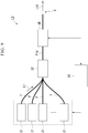
- FIG. 1 is a block diagram showing the configuration of a laser system provided with a photodetector 1A of the present embodiment.
- a laser system LS includes a plurality of laser devices 31, a combiner 32 (multiplexer), an optical fiber F10 (output optical fiber), a photodetector 1A, and a control device 33 (control unit).
- the laser system LS outputs output light L11 (laser light) from the output end X of the optical fiber F10.
- the laser device 31 is a device that outputs a laser beam under the control of the control device 33.
- the combiner 32 optically combines the plurality of beams of output light L1 output from the plurality of laser devices 31.
- the optical fibers F extending from respective laser devices 31 are bundled into one (made into one by melt drawing), and the one optical fiber is fusion-spliced to one end of the optical fiber F10.
- the optical fiber F10 is an optical fiber functioning as a transmission medium, and guides the output light L11 (light obtained by optically combining a plurality of beams of output light L1 output from the laser devices 31 by the combiner 32).
- the output light L11 guided by the optical fiber F10 is output from the output end X of the optical fiber F10.
- the control device 33 controls the plurality of laser devices 31 such that the power of the output light L11 output from the output end X becomes constant, based on the detection result to be described later of the photodetector 1A to be described later.
- the photodetector 1A is disposed between the combiner 32 and the output end X, and is configured to detect the power of light guided by the optical fiber F10.
- the photodetector 1A may be disposed between the laser device 31 and the combiner 32, and may detect the power of light guided by the optical fiber F.
- FIG. 2 is a perspective view of the photodetector 1A.
- the photodetector 1A includes a substrate 2, an optical fiber F10 or an optical fiber F (hereinafter simply referred to as an optical fiber F10) placed on the substrate 2, a first fixing member 3, a second fixing member 4, a fixing base 5, and a photodetection element 6.
- a Y direction is the extending direction (longitudinal direction) of the optical fiber F10 in a state before the optical fiber F10 moves due to a temperature change.
- a Z direction is a direction (vertical direction) perpendicular to the surface of the substrate 2 on which the optical fiber F10 is placed. In the Z direction, the side of the substrate 2 on which the optical fiber F10 is placed is referred to as the upper side, and the opposite side is referred to as the lower side.
- a X direction (transverse direction) is a direction orthogonal to both the Y direction and the Z direction.
- a first side of the optical fiber F10 in the X direction may be referred to as the -X side, and a second side may be referred to as the + X side.
- FIG. 3 is a top view of the photodetector 1A.
- FIG. 4 is a cross-sectional view taken along line A-A in FIG. 3 , and the outline of the second fixing member 4 is indicated by a two-dot chain line.
- FIG. 5 is a cross-sectional view taken along line B-B in FIG. 3 .
- the fixing base 5 has a main body 51 that holds the photodetection element 6 and a fastening portion 52 for fastening the fixing base 5 to the substrate 2.
- the fastening portion 52 of the fixing base 5 is fixed to the substrate 2 by a screw 8.
- the fixing base 5 is formed in a substantially rectangular parallelepiped shape having a depth of 20 mm, a width of 20 mm, and a height of 8 mm.
- a material of the fixing base 5 for example, aluminum surface-treated with matte black alumite can be used.
- a through hole 5a and a groove 5b are formed in the fixing base 5.
- the through hole 5a penetrates the main body 51 of the fixing base 5 in the Z direction, and extends perpendicularly to the substrate 2.
- the groove 5b is formed on the bottom surface of the main body 51 of the fixing base 5 and extends over the entire length of the fixing base 5 in the X direction. As shown in FIGS. 4 and 5 , the width in the X direction and the height in the Z direction of the groove 5b are larger than the diameter of the optical fiber F10.
- the fixing base 5 has openings 5b1, 5b2 of the groove 5b.
- a part of the optical fiber F10 is introduced into the groove 5b through the openings 5b1, 5b2 and is accommodated inside the fixing base 5.
- the first opening 5b1 is closed by the first fixing member 3, and the second opening 5b2 is closed by the second fixing member 4.
- a part of the first fixing member 3 enters the groove 5b through the first opening 5b1 and is located inside the fixing base 5.
- a part of the second fixing member 4 enters the groove 5b through the second opening 5b2 and is located inside the fixing base 5.
- the photodetection element 6 is formed with a cylindrical portion 6a and a flange portion 6b.
- the cylindrical portion 6a extends in the Z direction
- the flange portion 6b extends in a plane orthogonal to the Z direction.
- the photodetection element 6 is fixed to the fixing base 5 in a state where the positions in the X direction, the Y direction, and the Z direction with respect to the fixing base 5 are determined. Further, since the fixing base 5 is fixed to the substrate 2 by the screws 8, the photodetection element 6 is fixed to the substrate 2 through the fixing base 5. That is, the fixing base 5 fixes the photodetection element 6 to the substrate 2. Thus, the distance L between the lower end surface (hereinafter referred to as the light receiving surface 6c) of the cylindrical portion 6a of the photodetection element 6 and the outer peripheral surface of the optical fiber F10 is determined.
- the photodetection element 6 receives the scattered light (for example, Rayleigh scattered light) from the optical fiber F10 at the light receiving surface 6c, and converts the intensity of the scattered light into electric power.
- the electric power is amplified on an electric circuit board (not shown) and input to the control device 33.
- the control device 33 can monitor the power of the light guided by the optical fiber F10 in real time.
- a PIN photodiode can be used as the photodetection element 6.
- the distance L from the outer peripheral surface of the optical fiber F10 to the light receiving surface 6c is about several millimeters.
- the first fixing member 3 and the second fixing member 4 fix the optical fiber F10 to the substrate 2.
- the first fixing member 3 and the second fixing member 4 are disposed on both sides of the photodetection element 6 in the X direction. As shown in FIGS. 2 to 5 , the first fixing member 3 and the second fixing member 4 are formed in a substantially quarter-sphere shape. Parts of the first fixing member 3 and the second fixing member 4 respectively enter the groove 5b of the fixing base 5.
- the width of the first fixing member 3 or the second fixing member 4 in the X direction is referred to as a width W1.
- the width of the main body 51 in the X direction is referred to as a width W2.
- an end face of the main body 51, having the first opening 5b1 or the second opening 5b2 is referred to as an end face 51a.
- the end face 51a faces in the Y direction.
- the width W1 of the first fixing member 3 or the second fixing member 4 in the X direction (direction substantially orthogonal to the surface direction of the end face 51a) when viewed from the Y direction (longitudinal direction of the optical fiber F10) Is larger than the width W2 of the main body 51 in the X direction.
- the width of the first fixing member 3 or the second fixing member 4 in the Y direction (the surface direction of the end face 51a) in the main body 51 is referred to as a width W3.
- the width W1 and the width W3 of the first fixing member 3 or the second fixing member 4 are larger than the width W2 of the main body 51.
- the first fixing member 3 and the second fixing member 4 are each formed of a material having a positive linear expansion coefficient.
- a material of these fixing members for example, a silicon resin having a linear expansion coefficient of about 300 ⁇ 10 -6 [/K] can be used.
- the specific materials of the first fixing member 3 and the second fixing member 4 may be the same as or different from each other.
- the space where the light receiving surface 6c of the photodetection element 6 and the optical fiber F10 face each other is sealed by the photodetection element 6, the fixing base 5, the first fixing member 3, and the second fixing member 4. More specifically, the first fixing member 3 and the second fixing member 4 close the openings 5b1, 5b2 of the groove 5b formed in the fixing base 5.
- a part of either the first fixing member 3 or the second fixing member 4 is located inside the fixing base 5.
- the effect of fixing the optical fiber F10 to the substrate 2 can be further enhanced, compared with the case where a part of either the first fixing member 3 or the second fixing member 4 is not located inside the fixing base 5. Further, it is possible to more reliably prevent dust or the like from entering the fixing base 5. Then, the detection result of the scattered light by the photodetection element 6 can be further stabilized.
- a part of the first fixing member 3 or the second fixing member 4 is located inside the fixing base 5.
- FIG. 3 shows the case where the first fixing member 3 and the second fixing member 4 are formed in such a shape that the temperature dependency of the detection result of the photodetection element 6 becomes small.
- the volume V 1 of the portion of the first fixing member 3 on the first side (-X side) of the optical fiber F10 in the X direction and the volume V 2 of the portion on the second side (+ X side) are equal to each other.
- the volume V 3 of the portion of the second fixing member 4 on the first side (-X side) of the optical fiber F10 in the X direction and the volume V 4 of the portion on the second side (+ X side) are equal to each other.
- the center of gravity C3 of the first fixing member 3 and the center of gravity C4 of the second fixing member 4 are located on the optical fiber F10.
- a straight line connecting the centers of gravity C3, C4 in this ideal state is referred to as a center line O.
- first fixing member 3 and the second fixing member 4 are formed by curing the molten resin, for example, the first fixing member 3 and the second fixing member 4 are formed to be biased to the same side in the transverse direction.
- the case is considered where the first fixing member 3 and the second fixing member 4 are formed at positions shifted to the -X side with respect to the optical fiber F10.
- V 1 > V 2 and V 3 > V 4 and the centers of gravity C3, C4 of the respective fixing members are shifted to the -X side.
- FIG. 6B shows a state in which the temperature rises from the state of FIG. 6A and the first fixing member 3 and the second fixing member 4 thermally expand.
- the solid lines in FIG. 6B indicate the positions and shapes of the first fixing member 3, the second fixing member 4 and the optical fiber F10 after thermal expansion, and the broken lines indicate them before thermal expansion.
- the optical fiber F10 moves to the + X side. This is because the first fixing member 3 and the second fixing member 4 expand around the centers of gravity C3, C4. Since the movement amount ⁇ X of the optical fiber F10 due to thermal expansion is proportional to temperature, the distance between optical fiber F10 and photodetection element 6 changes with temperature. Thus, the detection result of the photodetection element 6 differs according to the temperature of the photodetector 1A, resulting in temperature dependency.
- the photodetector 1A of the present embodiment is formed with the first fixing member 3 and the second fixing member 4 so as to satisfy either V 1 > V 2 and V 3 ⁇ V 4 or V 1 ⁇ V 2 and V 3 > V 4 .
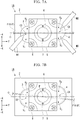
- a method of manufacturing the photodetector 1A will be described with reference to FIGS. 7A and 7B .
- the optical fiber F10 is placed on the upper surface of the substrate 2.
- the fixing base 5 is fixed to the substrate 2 with the screw 8, in a state where the optical fiber F10 is arranged along the groove 5b of the fixing base 5.
- the photodetection element 6 is fixed to the fixing base 5 by the screw 7.
- the heated and melted resin to be the first fixing member 3 is discharged from the tip of the nozzle N1 shown in FIG. 7A and applied onto the substrate 2 and the optical fiber F10.
- the application amount of the resin to be the first fixing member 3 is, for example, about 0.5 ml.
- the applied resin is cooled and solidified to form the first fixing member 3 (first application step).
- FIG. 7A shows a state in which the first fixing member 3 is formed to be biased to the -X side, and V 1 > V 2 . At this time, the center of gravity C3 of the first fixing member 3 is shifted to the -X side.
- volume detection step the volume V 1 of the portion on the -X side of the optical fiber F10 and the volume V 2 of the portion on the + X side of the formed first fixing member 3 are detected (volume detection step).
- the volumes V 1 , V 2 can be detected, for example, by an image recognition device (not shown).
- the volumes V 1 , V 2 may be detected before the first fixing member 3 is cured, or the volumes V 1 , V 2 may be detected after the first fixing member 3 is cured.
- the resin to be the second fixing member 4 is respectively discharged from the plurality of nozzles N2, N3 which are separately disposed on both the +X side and the -X side of the optical fiber F10, and is applied onto the substrate 2 and the optical fiber F10 (second application step).
- the total amount of resin to be the second fixing member 4 discharged from the nozzles N2, N3 is, for example, about 0.5 ml.
- the tip portions (discharge holes) of the nozzles N2, N3 are respectively disposed at equal intervals on the + X side and the -X side from the optical fiber F10.
- the resin discharged from the nozzles N2, N3 merges in the vicinity of the optical fiber F10 and is cooled to form the second fixing member 4.
- the discharge amount of at least one of the nozzles N2, N3 is controlled based on the detection result in the volume detection step. Specifically, for example, in a case where the volume detection result is V 1 > V 2 , it is controlled such that the discharge amount from the nozzle N2 is larger than the discharge amount from the nozzle N3.
- the second fixing member 4 is formed to be biased to the +X side, and V 3 ⁇ V 4 .
- the center of gravity C4 of the second fixing member 4 is shifted to the +X side.
- the discharge amounts from the nozzles N2, N3 are controlled such that V 3 > V 4 .
- FIG. 7B shows a state in which the temperature of the photodetector 1A rises from the state of FIG. 7A and the first fixing member 3 and the second fixing member 4 thermally expand.
- the first fixing member 3 expands around the center of gravity C3
- the optical fiber F10 is moved toward the + X side.
- the second fixing member 4 expands around the center of gravity C4
- the optical fiber F10 is moved toward the -X side.
- the optical fiber F10 is rotated about the point P in the vicinity of the photodetection element 6, for example, as compared to the case where V 1 > V 2 and V 3 > V 4 as shown in FIG. 6A , the movement amount of the optical fiber F10 relative to the photodetection element 6 can be reduced.
- the above-described operation is achieved even in the case where the photodetector 1A is configured to have V 1 ⁇ V 2 and V 3 > V 4 .
- the first fixing member 3 and the second fixing member 4 expand or contract around their respective centers of gravity C3, C4 with temperature change.
- the distance in the X direction between the center of gravity C3 of the first fixing member 3 and the optical fiber F10 in the top view is X 1 .
- the distance in the X direction between the center of gravity C4 of the second fixing member 4 and the optical fiber F10 in the top view is X 2 .
- the linear expansion coefficient of the first fixing member 3 is ⁇ 1
- the linear expansion coefficient of the second fixing member 4 is ⁇ 2 .
- the distance in the X direction between the center of gravity C3 and the optical fiber F10 is X 1 ⁇ T
- the distance in the X direction between the center of gravity C4 and the optical fiber F10 is X 2 ⁇ T .
- X 1 ⁇ T and X 2 ⁇ T can be expressed by the following expressions (1), (2).
- X 1 ⁇ ⁇ T X 1 ⁇ ⁇ 1 ⁇ ⁇ T + 1
- X 2 ⁇ ⁇ T X 2 ⁇ ⁇ 2 ⁇ ⁇ T + 1
- the conditions for the optical fiber F10 to rotate around the point P can be represented by following expression (3).
- X 1 ⁇ ⁇ T X 2 ⁇ ⁇ T
- the optical fiber F10 rotates around the point P in the vicinity of the photodetection element 6. Therefore, the temperature dependency of the detection result of the scattered light can be reduced.
- both the first fixing member 3 and the second fixing member 4 may be formed of a material having a positive linear expansion coefficient, and both may be formed of a material having a negative linear expansion coefficient.
- a material having a negative linear expansion coefficient for example, a synthetic resin as described in Japanese Patent No. 5699454 can be used.
- each fixing member expands when the temperature of the photodetector 1A rises. Therefore, it is possible to limit the bending of the optical fiber F10.
- the volumes of the first fixing member 3 and the second fixing member 4 are configured to satisfy either V 1 > V 2 and V 3 ⁇ V 4 or V 1 ⁇ V 2 and V 3 > V 4 , the optical fiber F10 is rotationally moved relative to the photodetection element 6 with the temperature change.
- V 1 > V 2 and V 3 > V 4 it is configured to satisfy V 1 > V 2 and V 3 > V 4 , as compared with the case where the optical fiber F10 moves in parallel with the photodetection element 6, it is possible to reduce the relative positional deviation between the optical fiber F10 and the photodetection element 6 due to the temperature change.
- the optical fiber F10 rotates around the vicinity of the photodetection element 6, it is possible to more reliably reduce the relative positional deviation between the photodetection element 6 and the optical fiber F10 due to a temperature change.
- the second fixing member 4 is formed by controlling a discharge amount from the plurality of nozzles N2, N3 such that the relative positional deviation between the photodetection element 6 and the optical fiber F10 due to the temperature change.
- the first fixing member 3 and the second fixing member 4 are formed such that the optical fiber F10 is rotationally moved with a temperature change, positional deviation between the optical fiber F10 and the photodetection element 6 due to temperature change can be more reliably reduced.
- the photodetection element 6 is fixed to the substrate 2 using the fixing base 5, but the photodetection element 6 may be fixed to the substrate 2 by another configuration without using such a fixing base 5.
- FIG. 7 shows an example in which the discharge holes of the nozzles N2, N3 are disposed at equal intervals in the transverse direction from the optical fiber F10, the present invention is not limited to this.
- the positions of the nozzles N2,N3 may be moved so as to satisfy either V 1 > V 2 and V 3 ⁇ V 4 or V 1 ⁇ V 2 and V 3 > V 4 , by changing the positions of the discharge holes of the nozzles N2,N3.
- FIG. 7 shows an example in which the resin to be the second fixing member 4 is discharged from the two nozzles N2, N3, but the present invention is not limited to this.
- V 1 > V 2 and V 3 ⁇ V 4 or V 1 ⁇ V 2 and V 3 > V 4 may be satisfied.
- V 1 > V 2 and V 3 ⁇ V 4 or V 1 ⁇ V 2 and V 3 > V 4 may be satisfied.
- the width W1 and the width W3 are larger than the width W2, but this relationship may be different. That is, the width W1 or the width W3 may be smaller than the width W2. In this case, the area of the portion of the substrate 2 covered by the first fixing member 3 or the second fixing member 4 is reduced. Therefore, since the mounting area of the other components on the substrate 2 is increased, it is possible to realize the photodetector 1A in which the mounting density of components is improved.
- the main body 51 of the fixing base 5 may be formed in a plate shape having a very small width in the Y direction.
- the fixing base 5 may not have the groove 5b, and may be provided with only the openings 5b1, 5b2.
- FIGS. 9 to 13 the scales of components are appropriately changed.
- FIG. 9 is a block diagram showing the configuration of a laser system LS provided with a photodetector 1B of the present embodiment.
- the laser system LS includes a plurality of laser devices 31, a combiner 32 (multiplexer), an optical fiber F10 (output optical fiber), the photodetector 1B, and a control device 33 (control unit).
- the laser system LS outputs output light L11 (laser light) from the output end X of the optical fiber F10.
- the laser device 31 is a device that outputs a laser beam under the control of the control device 33.
- the combiner 32 optically combines the plurality of beams of output light L1 output from the plurality of laser devices 31.
- the optical fibers F extending from respective laser devices 31 are bundled into one (made into one by melt drawing), and the one optical fiber is fusion-spliced to one end of the optical fiber F10.
- the optical fiber F10 is an optical fiber functioning as a transmission medium, and guides the output light L11 (light obtained by optically combining a plurality of beams of output light L1 output from the laser devices 31 by the combiner 32).
- the output light L11 guided by the optical fiber F10 is output from the output end X of the optical fiber F10.
- the control device 33 controls the plurality of laser devices 31 such that the power of the output light L11 output from the output end X becomes constant, based on the detection result to be described later of the photodetector 1B to be described later.
- the photodetector 1B is disposed between the combiner 32 and the output end X, and detects the power of light guided by the optical fiber F10.
- the photodetector 1B may be disposed between the laser device 31 and the combiner 32, and may detect the power of light guided by the optical fiber F.
- FIG. 10 is a perspective view of the photodetector 1B.
- the photodetector 1B includes a substrate 2, an optical fiber F10 or an optical fiber F (hereinafter simply referred to as an optical fiber F10) placed on the substrate 2, a first fixing member 3, a second fixing member 4, a fixing base 5, and a photodetection element 6.
- a direction in which the optical fiber F10 extends in a state before the optical fiber F10 moves due to a temperature change is referred to as a longitudinal direction.
- a direction which is perpendicular to the surface of the substrate 2 on which the optical fiber F10 is placed is referred to as the vertical direction.
- the vertical direction is orthogonal to the longitudinal direction.
- the side of the substrate 2 on which the optical fiber F10 is placed is referred to as the upper side, and the opposite side is referred to as the lower side.
- a direction orthogonal to the longitudinal direction and the vertical direction is referred to as the horizontal direction.
- FIG. 11 is a top view of the photodetector 1B.
- FIG. 12 is a cross-sectional view taken along line A-A in FIG. 11 , and the outline of the second fixing member 4 is indicated by a two-dot chain line.
- FIG. 13 is a cross-sectional view taken along line B-B in FIG. 11 .
- the fixing base 5 is fixed to the substrate 2 by a screw 8.
- the fixing base 5 is formed in a rectangular parallelepiped shape having a depth of 20 mm, a width of 20 mm, and a height of 8 mm.
- a material of the fixing base 5 for example, aluminum surface-treated with matte black alumite can be used.
- a through hole 5a and a groove 5b are formed in the fixing base 5.
- the through hole 5a penetrates the fixing base 5 in the vertical direction, and extends perpendicularly to the substrate 2.
- the groove 5b is formed on the bottom surface of the fixing base 5 and extends over the entire length of the fixing base 5 in the longitudinal direction.
- the width in the horizontal direction and the height in the vertical direction of the groove 5b are larger than the diameter of the optical fiber F10.
- the photodetection element 6 is formed with a cylindrical portion 6a and a flange portion 6b.
- the cylindrical portion 6a extends in the vertical direction
- the flange portion 6b extends in a plane orthogonal to the vertical direction.
- the photodetection element 6 is fixed to the fixing base 5 in a state where the positions in the longitudinal direction, the horizontal direction, and the vertical direction with respect to the fixing base 5 are determined. Further, since the fixing base 5 is fixed to the substrate 2 by the screws 8, the photodetection element 6 is fixed to the substrate 2 through the fixing base 5. That is, the fixing base 5 fixes the photodetection element 6 to the substrate 2. Thus, the distance L between the lower end surface (hereinafter referred to as the light receiving surface 6c) of the cylindrical portion 6a of the photodetection element 6 and the outer peripheral surface of the optical fiber F10 is determined.
- the photodetection element 6 receives the scattered light (for example, Rayleigh scattered light) from the optical fiber F10 at the light receiving surface 6c, and converts the intensity of the scattered light into electric power.
- the electric power is amplified on an electric circuit board (not shown) and input to the control device 33.
- the control device 33 can monitor the power of the light guided by the optical fiber F10 in real time.
- a PIN photodiode can be used as the photodetection element 6.
- the distance L from the outer peripheral surface of the optical fiber F10 to the light receiving surface 6c is about several millimeters.
- the first fixing member 3 and the second fixing member 4 fix the optical fiber F10 to the substrate 2.
- the first fixing member 3 and the second fixing member 4 are disposed on both sides of the photodetection element 6 in the longitudinal direction. As shown in FIGS. 10 to 13 , the first fixing member 3 and the second fixing member 4 are each formed in a substantially quarter-sphere shape. Parts of the first fixing member 3 and the second fixing member 4 respectively enter the groove 5b of the fixing base 5.
- the first fixing member 3 is formed of a material having a positive linear expansion coefficient.
- a material of the first fixing member 3 for example, a silicon resin having a linear expansion coefficient of about 300 ⁇ 10 -6 [/K] can be used.
- the second fixing member 4 is formed of a material having a negative linear expansion coefficient (for example, the material described in Japanese Patent No. 5699454 ).
- the second fixing member 4 in the present embodiment is formed of a material having a negative linear expansion coefficient in the longitudinal direction. Further, the second fixing member 4 in the present embodiment is formed of a material whose absolute value of the linear expansion coefficient is larger than the absolute value of the linear expansion coefficient of the material forming the first fixing member 3.
- first fixing member 3 and the second fixing member 4 described above are only an example, and other materials may be used as long as they have a positive linear expansion coefficient and a negative linear expansion coefficient, respectively.
- the space where the light receiving surface 6c of the photodetection element 6 and the optical fiber F10 face each other is sealed by the photodetection element 6, the fixing base 5, the first fixing member 3, and the second fixing member 4. More specifically, the first fixing member 3 and the second fixing member 4 close the opening of the groove 5b formed in the fixing base 5.
- the optical fiber F10 is placed on the upper surface of the substrate 2.
- the fixing base 5 is fixed to the substrate 2 with the screw 8, in a state where the optical fiber F10 is arranged along the groove 5b of the fixing base 5.
- the photodetection element 6 is fixed to the fixing base 5 by the screw 7.
- the first fixing member 3 and the second fixing member 4 which are heated and melted are applied in the vicinity of both ends of the groove 5b of the fixing base 5 in the longitudinal direction.
- the application amounts of the first fixing member 3 and the second fixing member 4 are, for example, about 0.5 ml, respectively.
- the first fixing member 3 and the second fixing member 4 are formed in a substantially quarter-sphere shape with a radius of about 6 mm, and a portion of the first fixing member 3 and the second fixing member 4 enters the groove 5b.
- the optical fiber F10 is fixed to the substrate 2 by the first fixing member 3 and the second fixing member 4.
- the photodetector 100 of Comparative Example includes a fixing member 40 formed of the same material as the first fixing member 3 instead of the second fixing member 4 in the photodetector 1B, as shown in FIG. 14A .
- FIG. 14A is a view showing a state in which the temperature of the photodetector 100 of Comparative Example rises, and the shapes of the first fixing member 3 and the fixing member 40 before deformation due to the temperature rise is shown by a two-dot chain line.
- the first fixing member 3 and the fixing member 40 are formed of a material having a positive linear expansion coefficient, it expand as the temperature rises, as shown in FIG. 14A . Therefore, in the optical fiber F10, all the portions fixed by the first fixing member 3 and the fixing member 40 move in the longitudinal direction toward the photodetection element 6. Thus, as shown in FIG. 14A , a part of the optical fibers F10 facing the photodetection element 6 may bend. Further, the deflection is not limited to the vertical direction, but may occur in the horizontal direction. In these cases, the distance between the optical fiber F10 and the light receiving surface 6c of the photodetection element 6 changes. Thus, the detection result of the scattered light by the photodetection element 6 changes.
- the first fixing member 3 and the fixing member 40 both contract.
- the temperature-dependent tension acts on the portion of the optical fiber F10 facing the photodetection element 6 in the vertical direction. The tension may affect the detection result of the scattered light by the photodetection element 6.
- the above-described temperature dependency can be reduced.
- FIG. 14B is a view showing a state in which the temperature of the photodetector 1B of FIG. 13 rises, and the shapes of the first fixing member 3 and the second fixing member 4 before deformation due to the temperature rise is shown by a two-dot chain line.
- the first fixing member 3 is formed of a material having a positive linear expansion coefficient, it expand as the temperature rises, as shown in FIG. 14B .
- the second fixing member 4 is formed of a material having a negative linear expansion coefficient, the second fixing member 4 contracts as the temperature rises, as shown in FIG. 14B .
- the second fixing member 4 contracts to absorb the movement in the longitudinal direction, and can prevent the optical fiber F10 from bending.
- the portion of the optical fiber F10 facing the photodetection element 6 in the vertical direction is moved from the first fixing member 3 side to the second fixing member 4 side, in the direction of the arrow shown in FIG. 14B .
- the bending of the optical fiber F10 can be limited.
- the first fixing member 3 contracts and the second fixing member 4 expands, the portion of the optical fiber F10 facing the photodetection element 6 in the vertical direction is moved from the second fixing member 4 side to the first fixing member 3 side, in the longitudinal direction.
- the bending of the optical fiber F10 can be limited.
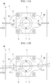
- FIG. 11 shows the case where the optical fiber F10 is at an ideal position in design.
- the ideal position in design is a position along a center line O connecting the center of gravity (hereinafter referred to as the center of gravity C3) of the first fixing member 3 and the center of gravity of the second fixing member 4 (hereinafter referred to as the center of gravity C4).
- the position of the optical fiber F10 is shifted from the center line O. More specifically, the optical fiber F10 deviates from the center of gravity C3 by X 0A , and deviates from the center of gravity C4 by X 0B .
- the position of the optical fiber F10 changes as shown in FIG. 15B .
- the portion of the optical fiber F10 fixed to the first fixing member 3 moves in the horizontal direction so as to be away from the center of gravity C3.
- the portion of the optical fiber F10 fixed to the second fixing member 4 moves in the left-right direction so as to approach the center of gravity C4.
- the optical fiber F10 In order to reduce the temperature dependency as described above, it is preferable to move the optical fiber F10 so as to rotate in a plane orthogonal to the vertical direction around the point P which is in the vicinity of the photodetection element 6. By moving in the horizontal direction in this manner, it is possible to minimize the change in the positional relationship between the optical fiber F10 and the light receiving surface 6c of the photodetection element 6.
- the condition for rotating the optical fiber F10 in the plane orthogonal to the vertical direction about the point P is that the movement amount of the optical fiber F10 in the horizontal direction due to the temperature change is equal in the portion fixed to the first fixing member 3 and the portion fixed to the second fixing member 4.
- the movement amount of the portion of the optical fiber F10 fixed to the first fixing member 3 in the horizontal direction is X ⁇ TA
- the movement amount of the portion fixed to the second fixing member 4 in the horizontal direction is X ⁇ TB
- the linear expansion coefficient of the material forming the first fixing member 3 is ⁇ A
- the absolute value of the linear expansion coefficient of the material forming the second fixing member 4 is ⁇ B
- the amount of change in temperature from the state shown in FIG. 15A is ⁇ T.
- X ⁇ TA and X ⁇ TB can be expressed by the following expressions (5), (6).
- X ⁇ ⁇ TA X 0 ⁇ A ⁇ ⁇ A ⁇ ⁇ T
- X ⁇ ⁇ TB X 0 ⁇ B ⁇ ⁇ B ⁇ ⁇ T
- Expression (9) shows the case where an error between the value of ⁇ A / ⁇ B and the value of X 0B /X 0A is within a range of ⁇ 1%.
- the optical fiber F10 is fixed to the substrate 2 by the first fixing member 3 and the second fixing member 4.
- the first fixing member 3 is formed of a material having a positive linear expansion coefficient
- the second fixing member 4 is formed of a material having a negative linear expansion coefficient. Therefore, in a case where a temperature change occurs in the first fixing member 3 and the second fixing member 4, one of the first fixing member 3 and the second fixing member 4 contracts, and the other expands. Then, the first fixing member 3 and the second fixing member 4 are disposed on both sides of the photodetection element 6 in the longitudinal direction.
- the optical fiber F10 rotates clockwise or counterclockwise with respect to this position.
- the relative positional deviation between the photodetection element 6 and the optical fiber F10 in the horizontal direction is reduced, and for example, it is possible to limit the relative positional deviation between the optical fiber F10 and the photodetection element6 in the horizontal direction caused by expansion of both the first fixing member 3 and the second fixing member 4. Further, the contraction of both the first fixing member 3 and the second fixing member 4 can limit the application of tension to the optical fiber F10.
- the second fixing member 4 is formed of a material having a negative linear expansion coefficient in the longitudinal direction, when the first fixing member 3 expands in the longitudinal direction as the temperature rises, the second fixing member 4 contracts in the longitudinal direction.
- the expansion of both the first fixing member 3 and the second fixing member 4 in the longitudinal direction can more reliably limit the floating of the optical fiber F10 with respect to the substrate.
- first fixing member 3 contracts in the longitudinal direction as the temperature falls, and the temperature change causes the second fixing member 4 to expand in the longitudinal direction.
- contraction of both the first fixing member 3 and the second fixing member 4 in the longitudinal direction can limit the application of tension to the optical fiber F10.
- the absolute value of the linear expansion coefficient of the material forming the second fixing member 4 is larger than the absolute value of the linear expansion coefficient of the material forming the first fixing member 3, when the temperature of the photodetector 1B rises, the amount of contraction of the volume of the second fixing member 4 exceeds the amount of expansion of the volume of the first fixing member 3. Mainly in the vertical direction or the horizontal direction, this makes it possible to more reliably limit the bending of the optical fiber F10 with respect to the substrate between the first fixing member 3 and the second fixing member 4. Further, this makes it possible to more reliably limit the change in the position of the optical fiber F10 with respect to the photodetection element 6.
- the photodetection element 6 is fixed to the substrate 2 using the fixing base 5, but the photodetection element 6 may be fixed to the substrate 2 by another configuration without using such a fixing base 5.
- the first fixing member 3 and the second fixing member 4 are disposed to straddle the optical fiber F10 in the lateral direction, but the present invention is not limited to this.
- the tip portions in the horizontal direction of the first fixing member 3 and the second fixing member 4 may be disposed so as to be in contact with the side surface of the optical fiber F10.
- the fixing base 5 of the photodetector 1B may have at least one opening, and a part of the optical fiber may be accommodated inside the fixing base 5 through the opening.
- the opening may be closed by either the first fixing member 3 or the second fixing member 4.
- a part of either first fixing member 3 or the second fixing member 4 may be located inside the fixing base 5 (inside the groove 5b).
- the first fixing member 3 or the second fixing member 4 may not be located inside the fixing base 5.
- the opening may not be closed by the first fixing member 3 or the second fixing member 4.
- FIG. 16 is a block diagram showing the configuration of a laser system LS provided with the photodetector 1C of the present embodiment.
- the laser system LS includes a plurality of laser devices 31, a combiner 32 (multiplexer), an optical fiber F10 (output optical fiber), the photodetector 1C, and a control device 33 (control unit).
- the laser system LS outputs output light L11 (laser light) from the output end X of the optical fiber F10.
- the laser device 31 is a device that outputs a laser beam under the control of the control device 33.
- the combiner 32 optically combines the plurality of beams of output light L1 output from the plurality of laser devices 31.
- the optical fibers F extending from respective laser devices 31 are bundled into one (made into one by melt drawing), and the one optical fiber is fusion-spliced to one end of the optical fiber F10.
- the optical fiber F10 is an optical fiber functioning as a transmission medium, and guides the output light L11 (light obtained by optically combining a plurality of beams of output light L1 output from the laser devices 31 by the combiner 32).
- the output light L11 guided by the optical fiber F10 is output from the output end X of the optical fiber F10.
- the control device 33 controls the plurality of laser devices 31 such that the power of the output light L11 output from the output end X becomes constant, based on the detection result to be described later of the photodetector 1C to be described later.
- the photodetector 1C is disposed between the combiner 32 and the output end X, and detects the power of light guided by the optical fiber F10.
- the photodetector 1C may be disposed between the laser device 31 and the combiner 32, and may detect the power of light guided by the optical fiber F.
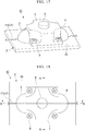
- FIG. 17 is a perspective view of the photodetector 1C according to the present embodiment.
- the photodetector 1C includes a substrate 2, a first fixing member 3, a second fixing member 4, a fixing base (element fixing base) 5, and a photodetection element 6.
- the photodetector 1C is located on the mounting surface 2a of the substrate 2 and detects the scattered light of light guided by an optical fiber F10 or an optical fiber F (hereinafter simply referred to as an optical fiber F10) partially placed on the mounting surface 2a.
- a direction in which the optical fiber F10 extends in a state before the optical fiber F10 moves due to a temperature change is referred to as a longitudinal direction.
- the direction perpendicular to the mounting surface 2a of the substrate 2 is referred to as the vertical direction.
- the vertical direction is orthogonal to the longitudinal direction.
- the mounting surface 2a side of the substrate 2 is referred to as the upper side, and the opposite side is referred to as the lower side.
- a direction orthogonal to the longitudinal direction and the vertical direction is referred to as the horizontal direction.
- FIG. 18 is a top view of the photodetector 1C as viewed from above.
- FIG. 19 is a cross-sectional view taken along line A-A in FIG. 18 .
- FIG. 20 is a cross-sectional view taken along line B-B in FIG. 18 .
- the fixing base 5 fixes the photodetection element 6 to the substrate 2.
- the fixing base 5 is configured to expand and contract at least in the vertical direction with temperature change.
- a vertically extending through hole is formed in a central portion of the fixing base 5 in a top view (plan view). As shown in FIGS. 19 and 20 , the through holes extend perpendicularly to the mounting surface 2a of the substrate 2.
- the through hole has a fitting portion 5f extending downward from the upper surface of the fixing base 5 and a reduced diameter portion 5e located below the fitting portion 5f.
- the fitting portion 5f and the reduced diameter portion 5e are coaxially disposed.
- the inner diameter of the fitting portion 5f is larger than the inner diameter of the reduced diameter portion 5e.
- the lower end (hereinafter referred to as a positioning portion 5d) of the fitting portion 5f is formed in an annular shape facing upward.
- the positioning portion 5d is located at the central portion in the vertical direction of the fixing base 5.
- the position of the photodetection element 6 in the vertical direction with respect to the mounting surface 2a of the substrate 2 is determined by the positioning portion 5d.
- the lower surface (hereinafter referred to as the contact surface 5c) of the fixing base 5 is in contact with the mounting surface 2a of the substrate 2. Further, as shown in FIG. 17 and the like, the fixing base 5 is fixed to the substrate 2 by a screw 8. Thus, the contact surface 5c of the fixing base 5 is fixed in contact with the mounting surface 2a of the substrate 2.
- the contact surface 5c of the fixing base 5 is formed with a groove 5b that is recessed upward.
- the groove 5b is disposed at the central portion in the horizontal direction of the fixing base 5 and partially intersects the reduced diameter portion 5e.
- the groove 5b extends over the entire length of the fixing base 5 in the longitudinal direction.
- the width in the horizontal direction and the height in the vertical direction of the groove 5b are larger than the diameter of the optical fiber F10.
- the fixing base 5 has openings 5b1, 5b2 of the groove 5b.
- a part of the optical fiber F10 is introduced into the groove 5b through the openings 5b1, 5b2 and is accommodated inside the fixing base 5.
- the first opening 5b1 is closed by the first fixing member 3, and the second opening 5b2 is closed by the second fixing member 4.
- a part of the first fixing member 3 enters the groove 5b through the first opening 5b1 and is located inside the fixing base 5.
- a part of the second fixing member 4 enters the groove 5b through the second opening 5b2 and is located inside the fixing base 5.
- a part of the optical fiber F10 is accommodated inside the groove 5b.
- the groove 5b of the fixing base 5 described above may be formed with a very small width in the longitudinal direction of the optical fiber F10.
- the fixing base 5 may not have the groove 5b, and may be provided with only the openings 5b1, 5b2.
- the photodetection element 6 receives the scattered light (for example, Rayleigh scattered light) from the optical fiber F10 at the bottom surface (hereinafter referred to as the light receiving surface 6c), and converts the intensity of the scattered light into electric power.
- the electric power is amplified on an electric circuit board (not shown) and input to the control device 33 (see FIG. 16 ).
- the control device 33 can monitor the power of the light guided by the optical fiber F10 in real time.
- a PIN photodiode can be used as the photodetection element 6.
- the distance from the outer peripheral surface of the optical fiber F10 to the light receiving surface 6c is about several millimeters.
- the photodetection element 6 is formed in a cylindrical shape as shown in FIGS. 17 and 18 . As shown in FIGS. 19 and 20 , when the outer peripheral surface of the photodetection element 6 is fitted in the fitting portion 5f of the fixing base 5, the positions of the photodetection element 6 in the longitudinal direction and the horizontal direction with respect to the fixing base 5 are determined.
- the position of the photodetection element 6 in the vertical direction with respect to the fixing base 5 is determined.
- the photodetection element 6 is fixed to the fixing base 5 in a state where the positions in the longitudinal direction, the horizontal direction, and the vertical direction with respect to the fixing base 5 are determined. Further, since the fixing base 5 is fixed to the substrate 2 by the screws 8, the photodetection element 6 is fixed to the substrate 2 through the fixing base 5. That is, the fixing base 5 fixes the photodetection element 6 to the substrate 2.
- the distance between the mounting surface 2a of the substrate 2 and the light receiving surface 6c of the photodetection element 6 in the vertical direction is determined by the length in the vertical direction from the contact surface 5c to the positioning portion 5d (hereinafter referred to as a light receiving surface height H b ).
- the first fixing member 3 and the second fixing member 4 fix the optical fiber F10 to the substrate 2.
- the first fixing member 3 and the second fixing member 4 are disposed on both sides of the photodetection element 6 in the longitudinal direction. As shown in FIGS. 17 to 20 , the first fixing member 3 and the second fixing member 4 are each formed in a substantially quarter-sphere shape. Parts of the first fixing member 3 and the second fixing member 4 respectively enter the groove 5b of the fixing base 5.
- the photodetector 1C of the present embodiment is provided with the connection member 9 fixed in contact with the mounting surface 2a of the substrate 2.
- the connection member 9 has a placing surface 9a on which the optical fiber F10 is placed.
- the connection member 9 connects the optical fiber F10 located on the placing surface 9a and the mounting surface 2a of the substrate 2.
- the connection member 9 is disposed at a portion that avoids the space between the mounting surface 2a of the substrate 2 and the contact surface 5c of the fixing base 5.
- the connection member 9 is disposed in a space defined by the inner wall of the reduced diameter portion 5e of the fixing base 5 and the mounting surface 2a of the substrate 2.
- the placing surface 9a of the connection member 9 is disposed at a portion facing at least the light receiving surface 6c of the photodetection element 6 with the optical fiber F10 interposed therebetween in the vertical direction.
- the connection member 9 may not partially face the light receiving surface 6c.
- the portion of the optical fiber F10 facing the photodetection element 6 is placed on the placing surface 9a, and the other portion of the optical fiber F10 is placed on the mounting surface 2a of the substrate 2.
- the distance hereinafter, simply referred to as a distance L
- the distance L in the vertical direction between the light receiving surface 6c of the photodetection element 6 and the outer peripheral surface of the optical fiber F10 is determined.
- the portions on both sides in the longitudinal direction of the portion of the optical fiber F10 facing the photodetection element 6 are fixed to the substrate 2 by the first fixing member 3 and the second fixing member 4.
- the optical fiber F10 is prevented from floating from the placing surface 9a and the distance L is prevented from fluctuating.
- connection member 9 may be made of, for example, a plate-like resin, and may be bonded to the mounting surface 2a of the substrate 2 by an adhesive or the like. Alternatively, the connection member 9 may be directly formed on the mounting surface 2a, by applying a UV curable resin or a thermosetting resin to be the connection member 9 on the mounting surface 2a to have a predetermined thickness (hereinafter referred to as a connection member thickness H a ).
- the manufacturing process of the photodetector 1C is, for example, as follows. First, a UV curable resin or thermosetting resin to be the connection member 9 is applied onto the mounting surface 2a of the substrate 2 and cured by UV light irradiation or heating. Next, the optical fiber F10 is placed on the placing surface 9a of the connection member 9. Next, the fixing base 5 to which the photodetection element 6 is attached in advance is covered from above the optical fiber F10 and the connection member 9. At this time, a part of the optical fiber F10 is accommodated in the groove 5b of the fixing base 5. Next, the fixing base 5 is fixed to the substrate 2 by the screws 8. Then, a UV curable resin or the like to be the first fixing member 3 and the second fixing member 4 is applied onto the optical fiber F10 and cured, and the optical fiber F10 is fixed to the substrate 2.
- the photodetection element 6 is fixed to the substrate 2 through the fixing base 5, and is fixed in a state where the contact surface 5c of the fixing base 5 is in contact with the mounting surface 2a of the substrate 2. Therefore, when the temperature of the photodetector 1C rises, the fixing base 5 thermally expands, and the photodetection element 6 moves upward with respect to the mounting surface 2a of the substrate 2.
- connection member 9 is disposed on the mounting surface 2a of the substrate 2, and the optical fiber F10 is placed on the placing surface 9a of the connection member 9. Portions of the optical fiber F10 positioned on both sides of the connection member 9 in the longitudinal direction are fixed on the mounting surface 2a of the substrate 2 by the first fixing member 3 and the second fixing member 4.
- the mounting surface 2a is located below the placing surface 9a. With this configuration, the portion of the optical fiber F10 placed on the placing surface 9a is pressed toward the placing surface 9a. Therefore, when the connection member 9 expands and contracts in the vertical direction, the portion of the optical fiber F10 placed on the placing surface 9a moves in the vertical direction in accordance with the expansion and contraction.
- the placing surface 9a is disposed at a portion facing at least the photodetection element 6 with the optical fiber F10 interposed therebetween in the vertical direction. Therefore, when the temperature of the photodetector 1C rises, the connection member 9 thermally expands, and the portion of the optical fiber F10 facing the photodetection element 6 moves upward with respect to the mounting surface 2a of the substrate 2.
- both the fixing base 5 and the connection member 9 thermally expand as the temperature rises, and both the photodetection element 6 and the optical fiber F10 are moved upward to the mounting surface 2a of the substrate 2.
- connection member 9 is configured to expand and contract at least in the vertical direction with the temperature change such that the distance L is within a predetermined range (for example, the change amount of the distance L due to the temperature change is within ⁇ 1%).
- the connection member 9 expands and contracts at least in the vertical direction with the temperature change such that the distance L is maintained within the above-described predetermined range.
- the user sets and determines a desired value, but it may be a value determined by the user in advance, specifically, as long as the relative positional deviation between the photodetection element 6 and the optical fiber F10 in the vertical direction can be limited.
- both the connection member 9 and the fixing base 5 thermally contract. Therefore, both the photodetection element 6 and the optical fiber F10 are moved downward to the mounting surface 2a of the substrate 2.
- the temperature rises it is possible to limit the relative positional deviation between the photodetection element 6 and the optical fiber F10 in the vertical direction caused by the temperature change.
- the fixing base 5 thermally expands or thermally contracts, so the photodetection element 6 moves in the vertical direction with respect to the mounting surface 2a of the substrate 2.
- the movement amount of the photodetection element 6 in the vertical direction at this time is calculated by
- the distance L fluctuates by the amount of movement of the photodetection element 6 in the vertical direction. That is, the fluctuation amount of the distance L in a case where the connection member 9 is not provided (hereinafter simply referred to as "the fluctuation amount ⁇ L r of the comparative example”) is expressed by the following Expression (10).
- ⁇ L r ⁇ T ⁇ ⁇ b ⁇ H b 0
- connection member 9 a case where a portion of the optical fiber F10 facing the light receiving surface 6c of the photodetection element 6 is placed on the connection member 9 will be considered.
- the linear expansion coefficient of the material forming the connection member 9 is ⁇ a
- the thickness in the vertical direction at the temperature T 0 of the portion of the connection member 9 on which the optical fiber F10 is placed is H a0 .
- the fixing base 5 thermally expands or thermally contracts, so the photodetection element 6 moves in the vertical direction with respect to the mounting surface 2a of the substrate 2.
- the portion of the optical fiber F10 facing the photodetection element 6 is placed on the connection member 9, and the connection member 9 also thermally expands or thermally contracts, so the optical fiber F10 also moves in the vertical direction with respect to the mounting surface 2a.
- the movement amount of the optical fiber F10 in the vertical direction at this time is calculated by
- the fluctuation amount of the distance L (hereinafter simply referred to as "the fluctuation amount ⁇ L e of the present embodiment") is a difference between the movement amount of the photodetection element 6 in the vertical direction and the movement amount of the optical fiber F10, and is expressed by the following Expression (11).
- ⁇ L e ⁇ T ⁇ ⁇ b ⁇ H b 0 ⁇ ⁇ T ⁇ ⁇ a ⁇ H a 0
- examples of a condition for satisfying Expression (11) include that the photodetection element 6 and the optical fiber F10 move in the same direction due to temperature change, but in this respect, the linear expansion coefficient ⁇ b of the fixing base 5 and the linear expansion coefficient ⁇ a of the connection member 9 may be both positive or both negative. That is, any one of ⁇ b > 0 and ⁇ a > 0, or ⁇ b ⁇ 0 and ⁇ a ⁇ 0 may be used.
- the condition for limiting the fluctuation of the distance L in the configuration in which the connection member 9 is provided as the present embodiment is that ⁇ L e ⁇ ⁇ L r .
- connection member 9 in a case where the material of the connection member 9 has a positive linear expansion coefficient (that is, in a case where ⁇ a is a positive value), ⁇ a ⁇ H a0 is a positive value, so ⁇ a ⁇ H a0 -2 ⁇ b ⁇ H b0 may be a negative value in order to satisfy Expression (12C).
- ⁇ a ⁇ H a0 -2 ⁇ b ⁇ H b0 is a negative value means a case where the amount of thermal expansion or thermal contraction of the connection member 9 does not excessively exceed the amount of thermal expansion or thermal contraction of the fixing base 5. That is, the provision of the connection member 9 means that the relative positional deviation caused by the temperature change of the photodetection element 6 and the optical fiber F10 does not increase.
- ⁇ a ⁇ H a0 -2 ⁇ b ⁇ H b0 may be a positive value in order to satisfy the condition of Expression (12C).
- this condition also means that the relative positional deviation caused by the temperature change of the photodetection element 6 and the optical fiber F10 does not increase by providing the connection member 9.
- connection member 9 and the fixing base 5 are configured to satisfy Expression (12C)
- the thermal expansion amount or thermal contraction amount of the connection member 9 excessively exceeds the thermal expansion amount or thermal contraction amount of the fixing base 5, and it is possible to limit an increase in relative positional deviation caused by the temperature change of the photodetection element 6 and optical fiber F10 more reliably by providing the connection member 9. Therefore, it is possible to limit more reliably the change in the detection result of the scattered light caused by the temperature change of the fixing base 5.
- the fluctuation amount ⁇ L e is expressed by Expression (11).
- connection member 9 and the fixing base 5 so as to satisfy the above Expression (13), the fluctuation of the distance L due to the temperature change becomes zero.
- both sides of the above Expression (13) do not need to have completely the same value, and if the value of ⁇ b ⁇ H b0 and the value of ⁇ a ⁇ H a0 are substantially the same, the amount of movement of the photodetection element 6 in the vertical direction with respect to the mounting surface 2a of the substrate 2 due to thermal expansion or thermal contraction of the fixing base 5 and the amount of movement of the optical fiber F10 in the vertical direction with respect to the mounting surface 2a of the substrate 2 due to thermal expansion or thermal contraction of the connection member 9 are substantially the same.
- the photodetection element 6 and the optical fiber F10 are displaced while maintaining the relative positional relationship in the vertical direction, and it is possible to further limit the relative positional deviation in the vertical direction of the both caused by the temperature change. Therefore, it is possible to further limit the change in the detection result of the scattered light caused by the temperature change of the fixing base 5.
- example of a case where the value of ⁇ b ⁇ H b0 and the value of ⁇ a ⁇ H a0 are substantially the same include a case where the following Expression (14) is satisfied.
- the above Expression (14) shows the case where an error between the value of ⁇ b ⁇ H b0 and the value of ⁇ a ⁇ H a0 is within ⁇ 1%. Since the connection member 9 is configured to expand and contract in the vertical direction so as to satisfy the above Expression (14), the fluctuation amount of the distance L due to the temperature change can be set within ⁇ 1% and can be kept.
- the photodetector 1C is mounted so as to detect the laser power in the optical fiber F10 of 125 ⁇ m located most downstream of the high-power laser system LS as shown in FIG. 16 .
- a photo detector (PD) in which the current value fluctuates according to the amount of received light is used.
- a material of the fixing base 5 aluminum surface-treated with matte black alumite is used.
- the linear expansion coefficient of this aluminum is 23 ⁇ 10 -6 [/K].
- the dimensions of the fixing base 5 are 20 mm in the longitudinal direction, 20 mm in the horizontal direction, and 60 mm in the vertical direction, and are formed in a rectangular parallelepiped shape as a whole.
- a resin having a linear expansion coefficient of 69 ⁇ 10 -6 [/K] is used as the material of the connection member 9 of the present embodiment.
- a laser of constant power is guided to the optical fiber F10, and the fluctuation of the current value of PD (hereinafter referred to as PD current fluctuation) in a case where the temperature of the photodetector 1C is changed from normal temperature (25 °C) to 80 °C is shown in FIG. 21 .
- the case where the thickness of the connection member 9 in the vertical direction is 0 mm indicates the case where the optical fiber F10 is directly placed on the mounting surface 2a of the substrate 2 without providing the connection member 9.
- the vertical axis of the graph shown in FIG. 21 is the PD current fluctuation [%] with reference to the state at normal temperature (25 °C), and the horizontal axis is the temperature [°C] of the photodetector 1C.
- connection member 9 in a case where the connection member 9 is not provided (in a case where the thickness of the connection member 9 is 0 mm), when the temperature of the photodetector 1C rises to 60 °C, there is a PD current fluctuation of about -0.06%. Since the power of the laser guided to the optical fiber F10 is constant, this means that the PD current fluctuation is caused by the fluctuation of the distance L shown in FIG. 16 , and the accuracy of the power detection result is lowered according to the temperature change.
- the value of the PD current fluctuation is limited to a small value as compared with the case where the connection member 9 is not provided. Specifically, in a case where the thickness of the connection member 9 in the vertical direction is 1 mm, the PD current fluctuation at 60 °C is about -0.05%.
- the PD current fluctuation at 60 °C is about +0.05%.
- the thickness of the connection member 9 in the vertical direction may be set within a range of 1 to 3 mm.
- the portion of the optical fiber F10 facing the photodetection element 6 in the vertical direction is placed on the placing surface 9a of the connection member 9, and the other portion is placed on the mounting surface 2a of the substrate 2, but the present invention is not limited to this.
- the placing surface 9a of the connection member 9 may extend over the entire length of the substrate 2 in the longitudinal direction, and the optical fiber F10 may be placed over the entire length of the placing surface 9a.
- the fixing base 5 of the photodetector 1C may have at least one opening, and a part of the optical fiber may be accommodated inside the fixing base 5 through the opening.
- the opening may be closed by either the first fixing member 3 or the second fixing member 4.
- a part of either the first fixing member 3 or the second fixing member 4 may be located inside the fixing base 5 (inside the groove 5b).
- the first fixing member 3 or the second fixing member 4 may not be located inside the fixing base 5.
- the opening may not be closed by the first fixing member 3 or the second fixing member 4.
- the configuration described in the second embodiment may be applied to the third embodiment.
- the first fixing member 3 of the photodetector 1C may be formed of a material having a positive linear expansion coefficient
- the second fixing member 4 may be formed of a material having a negative linear expansion coefficient.
- the first fixing member 3 of the photodetector 1A may be formed of a material having a positive linear expansion coefficient
- the second fixing member 4 may be formed of a material having a negative linear expansion coefficient
- the photodetector 1A may be fixed to the substrate 2 in contact with the mounting surface 2a of the substrate 2, and may include the connection member 9 having a placing surface 9a on which the optical fiber is placed, and connecting the optical fiber positioned on the placing surface 9a and the substrate 2.
- the fixing base 5 of the photodetector 1A may have a contact surface 5c fixed in contact with the mounting surface 2a, and the contact surface 5c may be disposed in a portion facing the photodetection element 6 with at least the optical fiber interposed therebetween.
- the connection member 9 may expand and contract at least in the vertical direction with the temperature change such that the distance in the vertical direction between the optical fiber placed on the placing surface 9a and the photodetection element 6 is within a predetermined range.
Landscapes
- Physics & Mathematics (AREA)
- General Physics & Mathematics (AREA)
- Optics & Photonics (AREA)
- Spectroscopy & Molecular Physics (AREA)
- Optical Couplings Of Light Guides (AREA)
- Light Receiving Elements (AREA)
- Photometry And Measurement Of Optical Pulse Characteristics (AREA)
Abstract
Description
- The present invention relates to a photodetector and a method for manufacturing a photodetector.
- Priority is claimed on Japanese Patent Application Nos.
2017-017430 2017-017476 2017-017477, filed on February 2, 2017 - In the related art, a photodetector as disclosed in
Patent Document 1 has been known. The photodetector includes a photodetection element that detects scattered light of light guided by an optical fiber. - In this type of photodetector, since the detection result of the scattered light changes depending on the relative positions of the photodetection element and the optical fiber, it is necessary to fix the photodetection element and the optical fiber by a fixing member or the like.
- [Patent Document 1] Published Japanese Translation No.
2013-508688 - Meanwhile, when the temperature of the fixing member changes due to a change in ambient temperature or the like, the fixing member may expand or contract, which may cause a shift in the relative positions of the photodetection element and the optical fiber. As a result, the detection result of the scattered light changes with the temperature change of the fixing member.
- The present invention has been made in view of such circumstances, and an object of the present invention is to provide a photodetector capable of limiting relative positional deviation between a photodetection element and an optical fiber caused by a temperature change.
- In order to solve the above problems, a photodetector according to a first aspect of the present invention includes a substrate, an optical fiber placed on the substrate; and a photodetection element that is fixed to the substrate, and is configured to detect scattered light of light guided by the optical fiber.
- In a photodetector according to a second aspect of the present invention, the photodetector according to the first aspect may further include a first fixing member and a second fixing member that fix the optical fiber to the substrate, in which the first fixing member is disposed on an opposite side of the photodetection element from the second fixing member in a longitudinal direction in which the optical fiber extends, when a volume of a portion of the first fixing member on a first side across the optical fiber in a transverse direction orthogonal to the longitudinal direction is V1 and a volume of a portion of the first fixing member on a second side opposite to the first side is V2, in top view, and a volume of a portion of the second fixing member on the first side of the optical fiber in the transverse direction is V3, and a volume of a portion of the second fixing member on the second side is V4, in top view, either V1 > V2 and V3 < V4, or V1 < V2 and V3 > V4 is satisfied.
- According to the second aspect, since the first fixing member and the second fixing member are configured to satisfy any one of V1 > V2 and V3 < V4 or V1 < V2 and V3 > V4, the optical fiber is rotationally moved relative to the photodetection element as the temperature changes. Thus, for example, as compared with the case where the photodetector is configured to satisfy V1 > V2 and V3 > V4, and the optical fiber moves in parallel with the photodetection element, it is possible to reduce the relative positional deviation between the optical fiber and the photodetection element due to the temperature change.
- According to a photodetector of a third aspect of the present invention, in the photodetector according to the second aspect, when a linear expansion coefficient of a material forming the first fixing member is α1, and a linear expansion coefficient of a material forming the second fixing member is α2, and in top view, a distance between a center of gravity of the first fixing member and the optical fiber in the transverse direction is X1, and a distance between a center of gravity of the second fixing member and the optical fiber in the transverse direction is X2, α1/α2 = X2/X1 is satisfied.
- According to the third aspect, since the optical fiber rotates around the vicinity of the photodetection element due to a temperature change, it is possible to more reliably reduce the relative positional deviation between the photodetection element and the optical fiber.
- A method for manufacturing a photodetector according to a fourth aspect is a method for manufacturing a photodetector including a substrate, an optical fiber which is placed on the substrate, a photodetection element which is fixed to the substrate, and is configured to detect scattered light of light guided by the optical fiber, and a first fixing member and a second fixing member which fix the optical fiber to the substrate, the first fixing member being disposed on an opposite side of the photodetection element from the second fixing member in a longitudinal direction in which the optical fiber extends, the method including: a first application step of applying a resin to be the first fixing member to the substrate and the optical fiber; a volume detection step of detecting a volume V1 of a portion of the first fixing member on a first side across the optical fiber in a transverse direction orthogonal to the longitudinal direction, and a volume V2 of a portion of the first fixing member on a second side opposite to the first side, in top view; and a second application step of applying a resin to be the second fixing member to the substrate and the optical fiber, based on a detection result in the volume detection step, in which when, in top view, a volume of a portion of the second fixing member on the first side in the transverse direction is V3, and a volume of a portion of the second fixing member on the second side is V4, a discharge amount of the resin to be the second fixing member is controlled such that either V1 > V2 and V3 < V4 or V1 < V2 and V3 > V4 is satisfied, in the second application step.
- According to the manufacturing method of the fourth aspect, since the resin to be the second fixing member is discharged based on the detection results of the volumes V1, V2 of the first fixing member, for example, in a case where the first fixing member is applied unevenly to the optical fiber in the transverse direction, the second fixing member is formed by controlling a discharge amount of the resin to be the second fixing member such that the relative positional deviation between the photodetection element and the optical fiber due to the temperature change.
- A photodetector according to a fifth aspect of the present invention is the photodetector according to any one of the first to third aspects further including a first fixing member and a second fixing member which fix the optical fiber to the substrate, in which the first fixing member is disposed on an opposite side of the photodetection element from the second fixing member in a longitudinal direction in which the optical fiber extends, and the first fixing member is formed of a material having a positive linear expansion coefficient, and the second fixing member is formed of a material having a negative linear expansion coefficient.
- According to the photodetector of the fifth aspect, the optical fiber is fixed to the substrate by the first fixing member and the second fixing member. Further, the first fixing member is formed of a material having a positive linear expansion coefficient, and the second fixing member is formed of a material having a negative linear expansion coefficient. Therefore, in a case where a temperature change occurs in the first fixing member and the second fixing member, one of the first fixing member and the second fixing member contracts, and the other expands. The first fixing member and the second fixing member are disposed on both sides of the photodetection element in the longitudinal direction of the optical fiber. Thus, for example, in a case where both the first fixing member and the second fixing member are formed of a material having a positive linear expansion coefficient, it is possible to limit the relative positional deviation between the optical fiber and the photodetection element caused by expansion of both the first fixing member and the second fixing member. Further, for example, in a case where both the first fixing member and the second fixing member are formed of a material having a negative linear expansion coefficient, it is possible to limit the application of tension to the optical fiber because both first fixing member and the second fixing member contract.
- A photodetector according to a sixth aspect of the present invention is the photodetector according to the fifth aspect, in which the second fixing member is formed of a material having a negative linear expansion coefficient in the longitudinal direction.
- A photodetector according to a seventh aspect of the present invention is the photodetector according to the fifth or sixth aspect, in which an absolute value of the linear expansion coefficient of the material forming the second fixing member is larger than an absolute value of the linear expansion coefficient of the material forming the first fixing member.
- According to the seventh aspect, since the contraction amount of the second fixing member exceeds the expansion amount of the first fixing member when the temperature of the photodetector rises, it is possible to more reliably limit bending of the optical fiber, for example, in the vertical direction or the horizontal direction between the first fixing member and the second fixing member, and a change in the position with respect to the photodetection element.
- A photodetector according to an eighth aspect of the present invention is the photodetector according to any one of the fifth to seventh aspects, in which when the linear expansion coefficient of a material forming the first fixing member is αA, and the absolute value of a linear expansion coefficient of a material forming the second fixing member is αB, and the distance between the center of gravity of the first fixing member and the optical fiber is X0A, and the distance between the center of gravity of the second fixing member and the optical fiber is X0B, the value of αA/αB and the value of X0B/X0A are approximately the same.
- According to the eighth aspect, in a case where the optical fiber is disposed out of the ideal design position, the optical fiber moves so as to rotate around the vicinity of the photodetection element as the temperature changes. Therefore, the amount of change in the distance of the optical fiber to the photodetection element depending on the temperature can be further reduced. Thereby, the temperature dependency of the detection result by the photodetection element can be further reduced.
- A photodetector according to a ninth aspect of the present invention is the photodetector according to any one of the first to third aspects and the fifth to eighth aspects further including a first fixing member and a second fixing member which fix the optical fiber to the substrate; and a fixing base which fixes the photodetection element to the substrate, in which the fixing base has at least one opening, a portion of the optical fiber is accommodated inside the fixing base through the opening, and the at least one opening is closed by either the first fixing member or the second fixing member.
- According to the ninth aspect, the opening for introducing the optical fiber to the inside of the fixing base is closed by the fixing member. Therefore, it is possible to prevent dust or the like from entering the fixing base through an opening and affecting the detection result of the scattered light by the photodetection element.
- A photodetector according to a tenth aspect of the present invention is the photodetector according to the ninth aspect in which a part of either the first fixing member or the second fixing member is located inside the fixing base.
- According to the tenth aspect, the effect of fixing the optical fiber to the substrate by the first fixing member or the second fixing member can be further enhanced. Further, it is possible to prevent dust or the like from entering a space where the light receiving surface of the photodetection element and the optical fiber face each other. Then, the detection result of the scattered light by the photodetection element can be further stabilized.
- A photodetector according to an eleventh aspect of the present invention is the photodetector according to the ninth or tenth aspect in which the fixing base has a main body that holds the photodetection element, and a width of either the first fixing member or the second fixing member is larger than a width of the main body.
- According to the eleventh aspect, the contact area of the first fixing member or the second fixing member and the substrate is increased. Therefore, the connection strength between the first fixing member or the second fixing member and the substrate increases, and the optical fiber can be fixed to the substrate more securely.
- A photodetector according to a twelfth aspect of the present invention is the photodetector according to the ninth or tenth aspect in which the fixing base has a main body that holds the photodetection element, and a width of either the first fixing member or the second fixing member is smaller than a width of the main body.
- According to the twelfth aspect, the area of the portion of the substrate covered by the first fixing member or the second fixing member is reduced. Therefore, since the area of the substrate on which other components can be mounted increases, the mounting density of components can be raised.
- A photodetector according to a thirteenth aspect of the present invention is the photodetector according to any one of the first to third or the fifth to twelfth aspects further including: a connection member which is fixed to the substrate in contact with a mounting surface of the substrate, has a placing surface on which the optical fiber is placed, and connects the optical fiber located on the placing surface and the substrate; a photodetection element that detects scattered light of light guided by the optical fiber; and a fixing base which fixes the photodetection element to the substrate, and expands and contracts at least in a vertical direction with a temperature change, in which the fixing base has at least one opening, and a contact surface fixed in contact with the mounting surface, a portion of the optical fiber is accommodated inside the fixing base through the opening, the placing surface is positioned at least a portion facing the photodetection element across at least the optical fiber, and the connection member expands and contracts at least in the vertical direction with a temperature change such that the distance in the vertical direction between the optical fiber located on the placing surface and the photodetection element is within a predetermined range.
- According to the photodetector in the thirteenth aspect, the photodetection element is fixed to the substrate through the fixing base, and is fixed in a state where the contact surface of the fixing base is in contact with the mounting surface of the substrate. Therefore, when the temperature of the photodetector rises or falls, the fixing base thermally expands or thermally contracts. Therefore, the photodetection element moves in the vertical direction with respect to the mounting surface of the substrate.
- On the other hand, the optical fiber is placed on the placing surface of the connection member, and the connection member is fixed in contact with the mounting surface of the substrate and connects the optical fiber located on the placing surface and the substrate. Further, the placing surface is disposed at a portion facing at least the photodetection element with at least the optical fiber interposed therebetween. Then, the connection member expands and contracts at least in the vertical direction with the temperature change such that the distance in the vertical direction between the optical fiber placed on the placing surface and the photodetection element is within a predetermined range. Thus, as compared with, for example, a case where the optical fiber is directly placed on the mounting surface of the substrate, it is possible to limit the relative positional deviation between the photodetection element and the optical fiber in the vertical direction caused by the temperature change.
- A photodetector according to a fourteenth aspect of the present invention is the photodetector according to the thirteenth aspect, in which the fixing base has a positioning unit which determines a position of the photodetection element in the vertical direction with respect to the mounting surface, a linear expansion coefficient of a material forming the connection member is αa, a linear expansion coefficient of a material forming the fixing base is αb, a thickness in the vertical direction of a portion of the connection member on which the optical fiber is placed is Ha0, and a length in the vertical direction from the contact surface to the positioning portion is Hb0, αa×Ha0(αa×Ha0-2×αb×Hb0) < 0 is satisfied.
- According to the fourteenth aspect, the connection member and the fixing base are configured to satisfy αa×Ha0(αa×Ha0-2×αb×Hb0) < 0. Thus, since the thermal expansion amount or thermal contraction amount of the connection member excessively exceeds the thermal expansion amount or thermal contraction amount of the fixing base, and the connection member is provided, it is possible to limit an increase in relative positional deviation in the vertical direction caused by the temperature change of the photodetection element and optical fiber, and to more reliably achieve the above-described effects of the photodetector.
- A photodetector according to a fifteenth aspect of the present invention is the photodetector according to the fourteenth aspect, in which a value of αb×Hb0 and a value of αa×Ha0 are substantially the same.
- According to the fifteenth aspect, the amount of movement of the photodetection element in the vertical direction with respect to the mounting surface of the substrate due to thermal expansion or thermal contraction of the fixing base and the amount of movement of the optical fiber in the vertical direction with respect to the mounting surface of the substrate due to thermal expansion or thermal contraction of the connection member are substantially the same. Thus, even if a temperature change occurs, the photodetection element and the optical fiber are displaced while maintaining the relative positional relationship in the vertical direction, and it is possible to more reliably limit the relative positional deviation in the vertical direction of the both caused by the temperature change.
- According to the above aspects of the present invention, it is possible to provide a photodetector capable of limiting relative positional deviation between a photodetection element and an optical fiber caused by a temperature change.
-
-
FIG. 1 is a block diagram showing a configuration of a laser system provided with a photodetector of a first embodiment. -
FIG. 2 is a perspective view of the photodetector of the first embodiment. -
FIG. 3 is a top view of the photodetector of the first embodiment. -
FIG. 4 is a cross-sectional view of the photodetector taken along line A-A inFIG. 3 . -
FIG. 5 is a cross-sectional view of the photodetector taken along line B-B inFIG. 3 . -
FIG. 6A is a top view showing a photodetector of a comparative example in which a first fixing member and a second fixing member are formed to be biased to the -X side, and shows a state before a temperature change. -
FIG. 6B is a view showing the state ofFIG. 6A after the temperature change. -
FIG. 7A is a top view of the photodetector of the present embodiment, showing a state before a temperature change. -
FIG. 7B is a view showing a state ofFIG. 7A after the temperature change. -
FIG. 8 is a top view of the photodetector of the first embodiment. -
FIG. 9 is a block diagram showing a configuration of a laser system provided with a photodetector of a second embodiment. -
FIG. 10 is a perspective view of the photodetector of the second embodiment. -
FIG. 11 is a top view of the photodetector of the second embodiment. -
FIG. 12 is a cross-sectional view of the photodetector taken along line A-A inFIG. 11 . -
FIG. 13 is a cross-sectional view of the photodetector taken along line B-B inFIG. 11 . -
FIG. 14A is an explanatory diagram of a case where a temperature of the photodetector of the comparative example rises. -
FIG. 14B is an explanatory diagram of a case where a temperature of the photodetector of the second embodiment rises. -
FIG. 15A is a top view showing a state in which the position of the optical fiber is shifted in the photodetector shown inFIG. 11 , and shows a state before a temperature change. -
FIG. 15B is a view showing a state ofFIG. 15A after the temperature change. -
FIG. 16 is a block diagram showing a configuration of a laser system provided with a photodetector of a third embodiment. -
FIG. 17 is a perspective view of the photodetector of the third embodiment. -
FIG. 18 is a top view of the photodetector of the third embodiment. -
FIG. 19 is a cross-sectional view of the photodetector taken along line A-A inFIG. 18 . -
FIG. 20 is a cross-sectional view of the photodetector taken along line B-B inFIG. 18 . -
FIG. 21 is a graph showing a fluctuation of a detection value by the photodetection element according to the temperature. - The configuration of a photodetector according to a first embodiment will be described below with reference to
FIGS. 1 to 8 - In order to facilitate understanding of the invention, in
FIGS. 1 to 8 , the scales of components are appropriately changed. -
FIG. 1 is a block diagram showing the configuration of a laser system provided with aphotodetector 1A of the present embodiment. - As shown in
FIG. 1 , a laser system LS includes a plurality oflaser devices 31, a combiner 32 (multiplexer), an optical fiber F10 (output optical fiber), aphotodetector 1A, and a control device 33 (control unit). The laser system LS outputs output light L11 (laser light) from the output end X of the optical fiber F10. - The
laser device 31 is a device that outputs a laser beam under the control of thecontrol device 33. - The
combiner 32 optically combines the plurality of beams of output light L1 output from the plurality oflaser devices 31. Inside thecombiner 32, the optical fibers F extending fromrespective laser devices 31 are bundled into one (made into one by melt drawing), and the one optical fiber is fusion-spliced to one end of the optical fiber F10. The optical fiber F10 is an optical fiber functioning as a transmission medium, and guides the output light L11 (light obtained by optically combining a plurality of beams of output light L1 output from thelaser devices 31 by the combiner 32). The output light L11 guided by the optical fiber F10 is output from the output end X of the optical fiber F10. - The
control device 33 controls the plurality oflaser devices 31 such that the power of the output light L11 output from the output end X becomes constant, based on the detection result to be described later of thephotodetector 1A to be described later. - The
photodetector 1A is disposed between thecombiner 32 and the output end X, and is configured to detect the power of light guided by the optical fiber F10. Thephotodetector 1A may be disposed between thelaser device 31 and thecombiner 32, and may detect the power of light guided by the optical fiber F. -
FIG. 2 is a perspective view of thephotodetector 1A. As shown inFIG. 2 , thephotodetector 1A includes asubstrate 2, an optical fiber F10 or an optical fiber F (hereinafter simply referred to as an optical fiber F10) placed on thesubstrate 2, a first fixingmember 3, asecond fixing member 4, a fixingbase 5, and aphotodetection element 6. - Here, in the present embodiment, an XYZ orthogonal coordinate system is set, and the positional relationship of each configuration will be described. A Y direction is the extending direction (longitudinal direction) of the optical fiber F10 in a state before the optical fiber F10 moves due to a temperature change. A Z direction is a direction (vertical direction) perpendicular to the surface of the
substrate 2 on which the optical fiber F10 is placed. In the Z direction, the side of thesubstrate 2 on which the optical fiber F10 is placed is referred to as the upper side, and the opposite side is referred to as the lower side. A X direction (transverse direction) is a direction orthogonal to both the Y direction and the Z direction. - Further, in top view (plan view), a first side of the optical fiber F10 in the X direction may be referred to as the -X side, and a second side may be referred to as the + X side.
-
FIG. 3 is a top view of thephotodetector 1A.FIG. 4 is a cross-sectional view taken along line A-A inFIG. 3 , and the outline of the second fixingmember 4 is indicated by a two-dot chain line.FIG. 5 is a cross-sectional view taken along line B-B inFIG. 3 . - As shown in
FIG. 2 and the like, the fixingbase 5 has amain body 51 that holds thephotodetection element 6 and afastening portion 52 for fastening the fixingbase 5 to thesubstrate 2. Thefastening portion 52 of the fixingbase 5 is fixed to thesubstrate 2 by ascrew 8. The fixingbase 5 is formed in a substantially rectangular parallelepiped shape having a depth of 20 mm, a width of 20 mm, and a height of 8 mm. As a material of the fixingbase 5, for example, aluminum surface-treated with matte black alumite can be used. As shown inFIGS. 4 and 5 , a throughhole 5a and agroove 5b are formed in the fixingbase 5. The throughhole 5a penetrates themain body 51 of the fixingbase 5 in the Z direction, and extends perpendicularly to thesubstrate 2. Thegroove 5b is formed on the bottom surface of themain body 51 of the fixingbase 5 and extends over the entire length of the fixingbase 5 in the X direction. As shown inFIGS. 4 and 5 , the width in the X direction and the height in the Z direction of thegroove 5b are larger than the diameter of the optical fiber F10. - As shown in
FIG. 5 , the fixingbase 5 has openings 5b1, 5b2 of thegroove 5b. A part of the optical fiber F10 is introduced into thegroove 5b through the openings 5b1, 5b2 and is accommodated inside the fixingbase 5. The first opening 5b1 is closed by the first fixingmember 3, and the second opening 5b2 is closed by the second fixingmember 4. A part of the first fixingmember 3 enters thegroove 5b through the first opening 5b1 and is located inside the fixingbase 5. A part of the second fixingmember 4 enters thegroove 5b through the second opening 5b2 and is located inside the fixingbase 5. - As shown in
FIG. 5 , thephotodetection element 6 is formed with acylindrical portion 6a and aflange portion 6b. Thecylindrical portion 6a extends in the Z direction, and theflange portion 6b extends in a plane orthogonal to the Z direction. When thecylindrical portion 6a is fitted in the throughhole 5a of the fixingbase 5, the positions of thephotodetection element 6 in the X and Y directions with respect to the fixingbase 5 are determined. Further, in a state where the lower surface of theflange portion 6b is in contact with the upper surface of the fixingbase 5, thephotodetection element 6 is fixed to the fixingbase 5 by thescrew 7. Thereby, the position of thephotodetection element 6 in the Z direction with respect to the fixingbase 5 is determined. - With the above configuration, the
photodetection element 6 is fixed to the fixingbase 5 in a state where the positions in the X direction, the Y direction, and the Z direction with respect to the fixingbase 5 are determined. Further, since the fixingbase 5 is fixed to thesubstrate 2 by thescrews 8, thephotodetection element 6 is fixed to thesubstrate 2 through the fixingbase 5. That is, the fixingbase 5 fixes thephotodetection element 6 to thesubstrate 2. Thus, the distance L between the lower end surface (hereinafter referred to as thelight receiving surface 6c) of thecylindrical portion 6a of thephotodetection element 6 and the outer peripheral surface of the optical fiber F10 is determined. - The
photodetection element 6 receives the scattered light (for example, Rayleigh scattered light) from the optical fiber F10 at thelight receiving surface 6c, and converts the intensity of the scattered light into electric power. The electric power is amplified on an electric circuit board (not shown) and input to thecontrol device 33. Thus, thecontrol device 33 can monitor the power of the light guided by the optical fiber F10 in real time. For example, a PIN photodiode can be used as thephotodetection element 6. In a case where a PIN photodiode is used as thephotodetection element 6, the distance L from the outer peripheral surface of the optical fiber F10 to thelight receiving surface 6c is about several millimeters. - The
first fixing member 3 and the second fixingmember 4 fix the optical fiber F10 to thesubstrate 2. Thefirst fixing member 3 and the second fixingmember 4 are disposed on both sides of thephotodetection element 6 in the X direction. As shown inFIGS. 2 to 5 , the first fixingmember 3 and the second fixingmember 4 are formed in a substantially quarter-sphere shape. Parts of the first fixingmember 3 and the second fixingmember 4 respectively enter thegroove 5b of the fixingbase 5. - As shown in
FIG. 4 , the width of the first fixingmember 3 or the second fixingmember 4 in the X direction is referred to as a width W1. The width of themain body 51 in the X direction is referred to as a width W2. As shown inFIGS. 2 and4 , an end face of themain body 51, having the first opening 5b1 or the second opening 5b2, is referred to as anend face 51a. Theend face 51a faces in the Y direction. As shown inFIG. 4 , the width W1 of the first fixingmember 3 or the second fixingmember 4 in the X direction (direction substantially orthogonal to the surface direction of theend face 51a) when viewed from the Y direction (longitudinal direction of the optical fiber F10) Is larger than the width W2 of themain body 51 in the X direction. - The width of the first fixing
member 3 or the second fixingmember 4 in the Y direction (the surface direction of theend face 51a) in themain body 51 is referred to as a width W3. In the present embodiment, the width W1 and the width W3 of the first fixingmember 3 or the second fixingmember 4 are larger than the width W2 of themain body 51. Thus, the contact area of the first fixingmember 3 and thesubstrate 2 is increased, and the contact area of the second fixingmember 4 and thesubstrate 2 is increased. Therefore, the connection strength between the first fixingmember 3 and thesubstrate 2 increases, and the connection strength between the second fixingmember 4 and thesubstrate 2 increases, and the optical fiber F10 can be fixed to thesubstrate 2 more securely. - The
first fixing member 3 and the second fixingmember 4 are each formed of a material having a positive linear expansion coefficient. As a material of these fixing members, for example, a silicon resin having a linear expansion coefficient of about 300×10-6 [/K] can be used. The specific materials of the first fixingmember 3 and the second fixingmember 4 may be the same as or different from each other. - As shown in
FIGS. 2 to 5 , the space where thelight receiving surface 6c of thephotodetection element 6 and the optical fiber F10 face each other is sealed by thephotodetection element 6, the fixingbase 5, the first fixingmember 3, and the second fixingmember 4. More specifically, the first fixingmember 3 and the second fixingmember 4 close the openings 5b1, 5b2 of thegroove 5b formed in the fixingbase 5. - With this configuration, it is possible to prevent dust or the like from entering the space where the
light receiving surface 6c of thephotodetection element 6 and the optical fiber F10 face each other and affecting the detection result of the scattered light by thephotodetection element 6. - Further, in the present embodiment, a part of either the first fixing
member 3 or the second fixingmember 4 is located inside the fixingbase 5. With this configuration, the effect of fixing the optical fiber F10 to thesubstrate 2 can be further enhanced, compared with the case where a part of either the first fixingmember 3 or the second fixingmember 4 is not located inside the fixingbase 5. Further, it is possible to more reliably prevent dust or the like from entering the fixingbase 5. Then, the detection result of the scattered light by thephotodetection element 6 can be further stabilized. In addition, a part of the first fixingmember 3 or the second fixingmember 4 is located inside the fixingbase 5. - Meanwhile,
FIG. 3 shows the case where the first fixingmember 3 and the second fixingmember 4 are formed in such a shape that the temperature dependency of the detection result of thephotodetection element 6 becomes small. Specifically, in top view, the volume V1 of the portion of the first fixingmember 3 on the first side (-X side) of the optical fiber F10 in the X direction and the volume V2 of the portion on the second side (+ X side) are equal to each other. Similarly, in top view, the volume V3 of the portion of the second fixingmember 4 on the first side (-X side) of the optical fiber F10 in the X direction and the volume V4 of the portion on the second side (+ X side) are equal to each other. That is, since the first fixingmember 3 and the second fixingmember 4 are formed such that V1 = V2 and, V3 = V4, the temperature dependency of thephotodetection element 6 is small. At this time, as shown inFIG. 3 , the center of gravity C3 of the first fixingmember 3 and the center of gravity C4 of the second fixingmember 4 are located on the optical fiber F10. A straight line connecting the centers of gravity C3, C4 in this ideal state is referred to as a center line O. - Here, since the first fixing
member 3 and the second fixingmember 4 are formed by curing the molten resin, for example, the first fixingmember 3 and the second fixingmember 4 are formed to be biased to the same side in the transverse direction. - For example, as shown in
FIG. 6A , the case is considered where the first fixingmember 3 and the second fixingmember 4 are formed at positions shifted to the -X side with respect to the optical fiber F10. In this case, V1 > V2 and V3 > V4, and the centers of gravity C3, C4 of the respective fixing members are shifted to the -X side. -
FIG. 6B shows a state in which the temperature rises from the state ofFIG. 6A and the first fixingmember 3 and the second fixingmember 4 thermally expand. The solid lines inFIG. 6B indicate the positions and shapes of the first fixingmember 3, the second fixingmember 4 and the optical fiber F10 after thermal expansion, and the broken lines indicate them before thermal expansion. - As shown in
FIG. 6B , with the thermal expansion of the first fixingmember 3 and the second fixingmember 4, the optical fiber F10 moves to the + X side. This is because the first fixingmember 3 and the second fixingmember 4 expand around the centers of gravity C3, C4. Since the movement amount ΔX of the optical fiber F10 due to thermal expansion is proportional to temperature, the distance between optical fiber F10 andphotodetection element 6 changes with temperature. Thus, the detection result of thephotodetection element 6 differs according to the temperature of thephotodetector 1A, resulting in temperature dependency. - Therefore, in order to reduce the temperature dependency, the
photodetector 1A of the present embodiment is formed with the first fixingmember 3 and the second fixingmember 4 so as to satisfy either V1 > V2 and V3 ≤ V4 or V1 < V2 and V3 > V4. Hereinafter, a method of manufacturing thephotodetector 1A will be described with reference toFIGS. 7A and 7B . - When manufacturing the
photodetector 1A, first, the optical fiber F10 is placed on the upper surface of thesubstrate 2. Next, the fixingbase 5 is fixed to thesubstrate 2 with thescrew 8, in a state where the optical fiber F10 is arranged along thegroove 5b of the fixingbase 5. Next, thephotodetection element 6 is fixed to the fixingbase 5 by thescrew 7. - Next, the heated and melted resin to be the first fixing
member 3 is discharged from the tip of the nozzle N1 shown inFIG. 7A and applied onto thesubstrate 2 and the optical fiber F10. The application amount of the resin to be the first fixingmember 3 is, for example, about 0.5 ml. The applied resin is cooled and solidified to form the first fixing member 3 (first application step). - Here, the tip of the nozzle N1 is disposed immediately above the optical fiber F10. The example of
FIG. 7A shows a state in which the first fixingmember 3 is formed to be biased to the -X side, and V1 > V2. At this time, the center of gravity C3 of the first fixingmember 3 is shifted to the -X side. - Next, the volume V1 of the portion on the -X side of the optical fiber F10 and the volume V2 of the portion on the + X side of the formed first fixing
member 3 are detected (volume detection step). The volumes V1, V2 can be detected, for example, by an image recognition device (not shown). In addition, in the volume detection step, the volumes V1, V2 may be detected before the first fixingmember 3 is cured, or the volumes V1, V2 may be detected after the first fixingmember 3 is cured. - Next, the resin to be the second fixing
member 4 is respectively discharged from the plurality of nozzles N2, N3 which are separately disposed on both the +X side and the -X side of the optical fiber F10, and is applied onto thesubstrate 2 and the optical fiber F10 (second application step). The total amount of resin to be the second fixingmember 4 discharged from the nozzles N2, N3 is, for example, about 0.5 ml. The tip portions (discharge holes) of the nozzles N2, N3 are respectively disposed at equal intervals on the + X side and the -X side from the optical fiber F10. The resin discharged from the nozzles N2, N3 merges in the vicinity of the optical fiber F10 and is cooled to form the second fixingmember 4. - Here, the discharge amount of at least one of the nozzles N2, N3 is controlled based on the detection result in the volume detection step. Specifically, for example, in a case where the volume detection result is V1 > V2, it is controlled such that the discharge amount from the nozzle N2 is larger than the discharge amount from the nozzle N3. Thus, as shown in
FIG. 7A , the second fixingmember 4 is formed to be biased to the +X side, and V3 < V4. At this time, the center of gravity C4 of the second fixingmember 4 is shifted to the +X side. - In addition, in a case where the volume detection result is V1 < V2, the discharge amounts from the nozzles N2, N3 are controlled such that V3 > V4. Further, in a case where the volume detection result is V1 = V2, the discharge amounts from the nozzles N2, N3 are controlled such that V3 = V4.
- Next, the operation of the
photodetector 1A manufactured in this manner will be described. -
FIG. 7B shows a state in which the temperature of thephotodetector 1A rises from the state ofFIG. 7A and the first fixingmember 3 and the second fixingmember 4 thermally expand. As shown inFIG. 7B , since the first fixingmember 3 expands around the center of gravity C3, the optical fiber F10 is moved toward the + X side. On the other hand, since the second fixingmember 4 expands around the center of gravity C4, the optical fiber F10 is moved toward the -X side. - Thus, since the optical fiber F10 is rotated about the point P in the vicinity of the
photodetection element 6, for example, as compared to the case where V1 > V2 and V3 > V4 as shown inFIG. 6A , the movement amount of the optical fiber F10 relative to thephotodetection element 6 can be reduced. - In addition, the above-described operation is achieved even in the case where the
photodetector 1A is configured to have V1 < V2 and V3 > V4. - Next, as shown in
FIG. 8 , in a case where V1 > V2 and V3 < V4, the relationship between the optical fiber F10 with respect to the centers of gravity C3, C4 and the linear expansion coefficients of the first fixingmember 3 and the second fixingmember 4 is considered. - As described above, the first fixing
member 3 and the second fixingmember 4 expand or contract around their respective centers of gravity C3, C4 with temperature change. Here, in order to reduce the temperature dependency of thephotodetection element 6, it is preferable to move the optical fiber F10 so as to rotate around a point P which is in the vicinity of thephotodetection element 6. By moving in this manner, it is possible to minimize the change in the positional relationship between the optical fiber F10 and thelight receiving surface 6c of thephotodetection element 6. - As shown in
FIG. 8 , the distance in the X direction between the center of gravity C3 of the first fixingmember 3 and the optical fiber F10 in the top view is X1. The distance in the X direction between the center of gravity C4 of the second fixingmember 4 and the optical fiber F10 in the top view is X2. Further, the linear expansion coefficient of the first fixingmember 3 is α1, and the linear expansion coefficient of the second fixingmember 4 is α2. - Here, after there is a temperature change of ΔT from the state shown in
FIG. 8 , the distance in the X direction between the center of gravity C3 and the optical fiber F10 is X1ΔT, and the distance in the X direction between the center of gravity C4 and the optical fiber F10 is X2ΔT. - At this time, X1ΔT and X2ΔT can be expressed by the following expressions (1), (2).


- The conditions for the optical fiber F10 to rotate around the point P can be represented by following expression (3).

- By substituting Expressions (1), (2) into both sides of Expression (3) and arranging, the following Expression (4) is obtained.

- By setting each condition so as to satisfy the above Expression (4), the optical fiber F10 rotates around the point P in the vicinity of the
photodetection element 6. Therefore, the temperature dependency of the detection result of the scattered light can be reduced. - In addition, both the first fixing
member 3 and the second fixingmember 4 may be formed of a material having a positive linear expansion coefficient, and both may be formed of a material having a negative linear expansion coefficient. As a material having a negative linear expansion coefficient, for example, a synthetic resin as described in Japanese Patent No.5699454 - In a case where both the first fixing
member 3 and the second fixingmember 4 are formed of a material having a negative linear expansion coefficient, for example, each fixing member expands when the temperature of thephotodetector 1A rises. Therefore, it is possible to limit the bending of the optical fiber F10. - As described above, in the
photodetector 1A of the present embodiment, the volumes of the first fixingmember 3 and the second fixingmember 4 are configured to satisfy either V1 > V2 and V3 ≤ V4 or V1 < V2 and V3 > V4, the optical fiber F10 is rotationally moved relative to thephotodetection element 6 with the temperature change. Thus, for example, it is configured to satisfy V1 > V2 and V3 > V4, as compared with the case where the optical fiber F10 moves in parallel with thephotodetection element 6, it is possible to reduce the relative positional deviation between the optical fiber F10 and thephotodetection element 6 due to the temperature change. - Further, in a case where it is configured to satisfy α1/α2 = X2/X1, the optical fiber F10 rotates around the vicinity of the
photodetection element 6, it is possible to more reliably reduce the relative positional deviation between thephotodetection element 6 and the optical fiber F10 due to a temperature change. - According to the manufacturing method of the
photodetector 1A of the present embodiment, since the resin to be the second fixingmember 4 is discharged from a plurality of nozzles N2, N3 disposed on both sides of the optical fiber F10, based on the detection results of the volumes V1, V2 of the first fixingmember 3, for example, in a case where the first fixingmember 3 is applied unevenly to the optical fiber F10 in the X direction, the second fixingmember 4 is formed by controlling a discharge amount from the plurality of nozzles N2, N3 such that the relative positional deviation between thephotodetection element 6 and the optical fiber F10 due to the temperature change. - Further, by controlling the discharge amount from at least one of the plurality of nozzles N2, N3 so as to satisfy either V1 > V2 and V3 < V4 or V1 < V2 and V3 > V4, the first fixing
member 3 and the second fixingmember 4 are formed such that the optical fiber F10 is rotationally moved with a temperature change, positional deviation between the optical fiber F10 and thephotodetection element 6 due to temperature change can be more reliably reduced. - It should be noted that the technical scope of the present invention is not limited to the above-described embodiments, and various modifications can be made without departing from the spirit of the present invention.
- For example, in the embodiment described above, the
photodetection element 6 is fixed to thesubstrate 2 using the fixingbase 5, but thephotodetection element 6 may be fixed to thesubstrate 2 by another configuration without using such afixing base 5. - Although
FIG. 7 shows an example in which the discharge holes of the nozzles N2, N3 are disposed at equal intervals in the transverse direction from the optical fiber F10, the present invention is not limited to this. For example, the positions of the nozzles N2,N3 may be moved so as to satisfy either V1 > V2 and V3 < V4 or V1 < V2 and V3 > V4, by changing the positions of the discharge holes of the nozzles N2,N3. - In addition,
FIG. 7 shows an example in which the resin to be the second fixingmember 4 is discharged from the two nozzles N2, N3, but the present invention is not limited to this. For example, by discharging the resin to be the second fixingmember 4 by one nozzle whose discharge hole is positioned on the center line O, either V1 > V2 and V3 < V4 or V1 < V2 and V3 > V4 may be satisfied. Alternatively, by discharging the resin to be the second fixingmember 4 from any one of the nozzle N2 and the nozzle N3, either V1 > V2 and V3 < V4 or V1 < V2 and V3 > V4 may be satisfied. - Further, in the first embodiment, the width W1 and the width W3 are larger than the width W2, but this relationship may be different. That is, the width W1 or the width W3 may be smaller than the width W2. In this case, the area of the portion of the
substrate 2 covered by the first fixingmember 3 or the second fixingmember 4 is reduced. Therefore, since the mounting area of the other components on thesubstrate 2 is increased, it is possible to realize thephotodetector 1A in which the mounting density of components is improved. - Further, the
main body 51 of the fixingbase 5 may be formed in a plate shape having a very small width in the Y direction. In this case, the fixingbase 5 may not have thegroove 5b, and may be provided with only the openings 5b1, 5b2. - The configuration of a
photodetector 1B according to the present embodiment will be described below with reference toFIGS. 9 to 13 . - In order to facilitate understanding of the invention, in
FIGS. 9 to 13 , the scales of components are appropriately changed. -
FIG. 9 is a block diagram showing the configuration of a laser system LS provided with aphotodetector 1B of the present embodiment. - As shown in
FIG. 9 , the laser system LS includes a plurality oflaser devices 31, a combiner 32 (multiplexer), an optical fiber F10 (output optical fiber), thephotodetector 1B, and a control device 33 (control unit). The laser system LS outputs output light L11 (laser light) from the output end X of the optical fiber F10. - The
laser device 31 is a device that outputs a laser beam under the control of thecontrol device 33. - The
combiner 32 optically combines the plurality of beams of output light L1 output from the plurality oflaser devices 31. Inside thecombiner 32, the optical fibers F extending fromrespective laser devices 31 are bundled into one (made into one by melt drawing), and the one optical fiber is fusion-spliced to one end of the optical fiber F10. The optical fiber F10 is an optical fiber functioning as a transmission medium, and guides the output light L11 (light obtained by optically combining a plurality of beams of output light L1 output from thelaser devices 31 by the combiner 32). The output light L11 guided by the optical fiber F10 is output from the output end X of the optical fiber F10. - The
control device 33 controls the plurality oflaser devices 31 such that the power of the output light L11 output from the output end X becomes constant, based on the detection result to be described later of thephotodetector 1B to be described later. - The
photodetector 1B is disposed between thecombiner 32 and the output end X, and detects the power of light guided by the optical fiber F10. In addition, thephotodetector 1B may be disposed between thelaser device 31 and thecombiner 32, and may detect the power of light guided by the optical fiber F. -
FIG. 10 is a perspective view of thephotodetector 1B. As shown inFIG. 10 , thephotodetector 1B includes asubstrate 2, an optical fiber F10 or an optical fiber F (hereinafter simply referred to as an optical fiber F10) placed on thesubstrate 2, a first fixingmember 3, asecond fixing member 4, a fixingbase 5, and aphotodetection element 6. - In addition, in the present embodiment, a direction in which the optical fiber F10 extends in a state before the optical fiber F10 moves due to a temperature change is referred to as a longitudinal direction. Further, a direction which is perpendicular to the surface of the
substrate 2 on which the optical fiber F10 is placed is referred to as the vertical direction. The vertical direction is orthogonal to the longitudinal direction. In the vertical direction, the side of thesubstrate 2 on which the optical fiber F10 is placed is referred to as the upper side, and the opposite side is referred to as the lower side. Further, a direction orthogonal to the longitudinal direction and the vertical direction is referred to as the horizontal direction. -
FIG. 11 is a top view of thephotodetector 1B.FIG. 12 is a cross-sectional view taken along line A-A inFIG. 11 , and the outline of the second fixingmember 4 is indicated by a two-dot chain line.FIG. 13 is a cross-sectional view taken along line B-B inFIG. 11 . - As shown in
FIG. 10 and the like, the fixingbase 5 is fixed to thesubstrate 2 by ascrew 8. The fixingbase 5 is formed in a rectangular parallelepiped shape having a depth of 20 mm, a width of 20 mm, and a height of 8 mm. As a material of the fixingbase 5, for example, aluminum surface-treated with matte black alumite can be used. As shown inFIGS. 12 and 13 , a throughhole 5a and agroove 5b are formed in the fixingbase 5. The throughhole 5a penetrates the fixingbase 5 in the vertical direction, and extends perpendicularly to thesubstrate 2. Thegroove 5b is formed on the bottom surface of the fixingbase 5 and extends over the entire length of the fixingbase 5 in the longitudinal direction. As shown inFIGS. 12 and 13 , the width in the horizontal direction and the height in the vertical direction of thegroove 5b are larger than the diameter of the optical fiber F10. - As shown in
FIG. 13 , thephotodetection element 6 is formed with acylindrical portion 6a and aflange portion 6b. Thecylindrical portion 6a extends in the vertical direction, and theflange portion 6b extends in a plane orthogonal to the vertical direction. When thecylindrical portion 6a is fitted in the throughhole 5a of the fixingbase 5, the positions of thephotodetection element 6 in the longitudinal direction and the horizontal direction with respect to the fixingbase 5 are determined. Further, in a state where the lower surface of theflange portion 6b is in contact with the upper surface of the fixingbase 5, thephotodetection element 6 is fixed to the fixingbase 5 by thescrew 7. Thus, the position of thephotodetection element 6 in the vertical direction with respect to the fixingbase 5 is determined. - With the above configuration, the
photodetection element 6 is fixed to the fixingbase 5 in a state where the positions in the longitudinal direction, the horizontal direction, and the vertical direction with respect to the fixingbase 5 are determined. Further, since the fixingbase 5 is fixed to thesubstrate 2 by thescrews 8, thephotodetection element 6 is fixed to thesubstrate 2 through the fixingbase 5. That is, the fixingbase 5 fixes thephotodetection element 6 to thesubstrate 2. Thus, the distance L between the lower end surface (hereinafter referred to as thelight receiving surface 6c) of thecylindrical portion 6a of thephotodetection element 6 and the outer peripheral surface of the optical fiber F10 is determined. - The
photodetection element 6 receives the scattered light (for example, Rayleigh scattered light) from the optical fiber F10 at thelight receiving surface 6c, and converts the intensity of the scattered light into electric power. The electric power is amplified on an electric circuit board (not shown) and input to thecontrol device 33. Thus, thecontrol device 33 can monitor the power of the light guided by the optical fiber F10 in real time. For example, a PIN photodiode can be used as thephotodetection element 6. In a case where a PIN photodiode is used as thephotodetection element 6, the distance L from the outer peripheral surface of the optical fiber F10 to thelight receiving surface 6c is about several millimeters. - The
first fixing member 3 and the second fixingmember 4 fix the optical fiber F10 to thesubstrate 2. Thefirst fixing member 3 and the second fixingmember 4 are disposed on both sides of thephotodetection element 6 in the longitudinal direction. As shown inFIGS. 10 to 13 , the first fixingmember 3 and the second fixingmember 4 are each formed in a substantially quarter-sphere shape. Parts of the first fixingmember 3 and the second fixingmember 4 respectively enter thegroove 5b of the fixingbase 5. - The
first fixing member 3 is formed of a material having a positive linear expansion coefficient. As a material of the first fixingmember 3, for example, a silicon resin having a linear expansion coefficient of about 300×10-6 [/K] can be used. - The
second fixing member 4 is formed of a material having a negative linear expansion coefficient (for example, the material described in Japanese Patent No.5699454 - In addition, the second fixing
member 4 in the present embodiment is formed of a material having a negative linear expansion coefficient in the longitudinal direction. Further, the second fixingmember 4 in the present embodiment is formed of a material whose absolute value of the linear expansion coefficient is larger than the absolute value of the linear expansion coefficient of the material forming the first fixingmember 3. - In addition, the materials of the first fixing
member 3 and the second fixingmember 4 described above are only an example, and other materials may be used as long as they have a positive linear expansion coefficient and a negative linear expansion coefficient, respectively. - In addition, as shown in
FIGS. 10 to 13 , the space where thelight receiving surface 6c of thephotodetection element 6 and the optical fiber F10 face each other is sealed by thephotodetection element 6, the fixingbase 5, the first fixingmember 3, and the second fixingmember 4. More specifically, the first fixingmember 3 and the second fixingmember 4 close the opening of thegroove 5b formed in the fixingbase 5. - With this configuration, it is possible to prevent dust or the like from entering the space where the
light receiving surface 6c of thephotodetection element 6 and the optical fiber F10 face each other and affecting the detection result of the scattered light by thephotodetection element 6. - When assembling the
photodetector 1B, first, the optical fiber F10 is placed on the upper surface of thesubstrate 2. Next, the fixingbase 5 is fixed to thesubstrate 2 with thescrew 8, in a state where the optical fiber F10 is arranged along thegroove 5b of the fixingbase 5. Next, thephotodetection element 6 is fixed to the fixingbase 5 by thescrew 7. Next, the first fixingmember 3 and the second fixingmember 4 which are heated and melted are applied in the vicinity of both ends of thegroove 5b of the fixingbase 5 in the longitudinal direction. The application amounts of the first fixingmember 3 and the second fixingmember 4 are, for example, about 0.5 ml, respectively. Thus, the first fixingmember 3 and the second fixingmember 4 are formed in a substantially quarter-sphere shape with a radius of about 6 mm, and a portion of the first fixingmember 3 and the second fixingmember 4 enters thegroove 5b. When the first fixingmember 3 and the second fixingmember 4 are cooled and solidified, the optical fiber F10 is fixed to thesubstrate 2 by the first fixingmember 3 and the second fixingmember 4. - Next, the operation of the
photodetector 1B configured as described above will be described in comparison with thephotodetector 100 of the comparative example. - The
photodetector 100 of Comparative Example includes a fixingmember 40 formed of the same material as the first fixingmember 3 instead of the second fixingmember 4 in thephotodetector 1B, as shown inFIG. 14A . -
FIG. 14A is a view showing a state in which the temperature of thephotodetector 100 of Comparative Example rises, and the shapes of the first fixingmember 3 and the fixingmember 40 before deformation due to the temperature rise is shown by a two-dot chain line. - Since the first fixing
member 3 and the fixingmember 40 are formed of a material having a positive linear expansion coefficient, it expand as the temperature rises, as shown inFIG. 14A . Therefore, in the optical fiber F10, all the portions fixed by the first fixingmember 3 and the fixingmember 40 move in the longitudinal direction toward thephotodetection element 6. Thus, as shown inFIG. 14A , a part of the optical fibers F10 facing thephotodetection element 6 may bend. Further, the deflection is not limited to the vertical direction, but may occur in the horizontal direction. In these cases, the distance between the optical fiber F10 and thelight receiving surface 6c of thephotodetection element 6 changes. Thus, the detection result of the scattered light by thephotodetection element 6 changes. - In addition, in a case where the temperature falls, the first fixing
member 3 and the fixingmember 40 both contract. Theremore, the temperature-dependent tension acts on the portion of the optical fiber F10 facing thephotodetection element 6 in the vertical direction. The tension may affect the detection result of the scattered light by thephotodetection element 6. - As described above, in the
photodetector 100 of the comparative example, temperature dependency occurs in the detection result of the scattered light by thephotodetection element 6. - On the other hand, in the
photodetector 1B of the present embodiment, the above-described temperature dependency can be reduced. -
FIG. 14B is a view showing a state in which the temperature of thephotodetector 1B ofFIG. 13 rises, and the shapes of the first fixingmember 3 and the second fixingmember 4 before deformation due to the temperature rise is shown by a two-dot chain line. - Since the first fixing
member 3 is formed of a material having a positive linear expansion coefficient, it expand as the temperature rises, as shown inFIG. 14B . On the other hand, since the second fixingmember 4 is formed of a material having a negative linear expansion coefficient, the second fixingmember 4 contracts as the temperature rises, as shown inFIG. 14B . Thus, even if the portion of the optical fiber F10 fixed by the first fixingmember 3 moves in the longitudinal direction toward thephotodetection element 6 side due to expansion of the first fixingmember 3, the second fixingmember 4 contracts to absorb the movement in the longitudinal direction, and can prevent the optical fiber F10 from bending. That is, in a case where the temperature rises, the portion of the optical fiber F10 facing thephotodetection element 6 in the vertical direction is moved from the first fixingmember 3 side to the second fixingmember 4 side, in the direction of the arrow shown inFIG. 14B . Thus, the bending of the optical fiber F10 can be limited. - Further, in a case where the temperature falls, the first fixing
member 3 contracts and the second fixingmember 4 expands, the portion of the optical fiber F10 facing thephotodetection element 6 in the vertical direction is moved from the second fixingmember 4 side to the first fixingmember 3 side, in the longitudinal direction. Thus, the bending of the optical fiber F10 can be limited. - Here, a case is considered where the position of the optical fiber F10 is fixed by being shifted from the ideal position in design.
FIG. 11 shows the case where the optical fiber F10 is at an ideal position in design. The ideal position in design is a position along a center line O connecting the center of gravity (hereinafter referred to as the center of gravity C3) of the first fixingmember 3 and the center of gravity of the second fixing member 4 (hereinafter referred to as the center of gravity C4). - On the other hand, in the state shown in
FIG. 15A , the position of the optical fiber F10 is shifted from the center line O. More specifically, the optical fiber F10 deviates from the center of gravity C3 by X0A, and deviates from the center of gravity C4 by X0B. - As shown in
FIG. 15A , when the optical fiber F10 is fixed at a position shifted from the center line O, in a case where the temperature rises, the position of the optical fiber F10 changes as shown inFIG. 15B . Specifically, as the first fixingmember 3 expands, the portion of the optical fiber F10 fixed to the first fixingmember 3 moves in the horizontal direction so as to be away from the center of gravity C3. Then, as the second fixingmember 4 contracts, the portion of the optical fiber F10 fixed to the second fixingmember 4 moves in the left-right direction so as to approach the center of gravity C4. Due to this change in position, the positional relationship between the light receivingsurface 6c of thephotodetection element 6 and the optical fiber F10 may change, and a temperature dependency may occur in the detection result of the scattered light. Therefore, conditions for reducing this temperature dependency are examined. - In order to reduce the temperature dependency as described above, it is preferable to move the optical fiber F10 so as to rotate in a plane orthogonal to the vertical direction around the point P which is in the vicinity of the
photodetection element 6. By moving in the horizontal direction in this manner, it is possible to minimize the change in the positional relationship between the optical fiber F10 and thelight receiving surface 6c of thephotodetection element 6. The condition for rotating the optical fiber F10 in the plane orthogonal to the vertical direction about the point P is that the movement amount of the optical fiber F10 in the horizontal direction due to the temperature change is equal in the portion fixed to the first fixingmember 3 and the portion fixed to the second fixingmember 4. - As shown in
FIG. 15B , the movement amount of the portion of the optical fiber F10 fixed to the first fixingmember 3 in the horizontal direction is XΔTA, and the movement amount of the portion fixed to the second fixingmember 4 in the horizontal direction is XΔTB. The linear expansion coefficient of the material forming the first fixingmember 3 is αA, and the absolute value of the linear expansion coefficient of the material forming the second fixingmember 4 is αB. Further, the amount of change in temperature from the state shown inFIG. 15A is ΔT. At this time, XΔTA and XΔTB can be expressed by the following expressions (5), (6).

- The conditions for the optical fiber F10 to rotate in a plane orthogonal to the vertical direction around the point P can be represented by following Expression (7).

- By substituting Expressions (5), (6) into both sides of Expression (7) and arranging, the following Expression (8) is obtained.

- By setting each condition so as to satisfy the above Expression (8), even when the temperature change occurs in the
photodetector 1B, the optical fiber F10 rotates clockwise or counterclockwise in the plane orthogonal to the vertical direction around the point P while further keeping the relative positions of thephotodetection element 6 and the optical fiber F10 in the horizontal direction. Thus, it is possible to further reduce the relative positional deviation between thephotodetection element 6 and the optical fiber F10 in the horizontal direction caused by the temperature change. Therefore, the temperature dependency of the detection result of the scattered light can be reduced. - In addition, without being limited to the case where both sides have the same value as in the above Expression (8), even if the value of αA/αB and the value of X0B/X0A are substantially the same, the temperature dependency of the detection result of the scattered light described above can be reduced. Substantially same refers to, for example, the case where Expression (9) is satisfied.

- Expression (9) shows the case where an error between the value of αA/αB and the value of X0B/X0A is within a range of ±1%.
- In addition, even in a case where the optical fiber F10 and the center line O overlap, that is, X0A = 0 and X0B = 0, it is possible to prevent the relative positions of the optical fiber F10 and the
photodetection element 6 from changing with the temperature change as described above. - As described above, according to the
photodetector 1B of the present embodiment, the optical fiber F10 is fixed to thesubstrate 2 by the first fixingmember 3 and the second fixingmember 4. Further, the first fixingmember 3 is formed of a material having a positive linear expansion coefficient, and the second fixingmember 4 is formed of a material having a negative linear expansion coefficient. Therefore, in a case where a temperature change occurs in the first fixingmember 3 and the second fixingmember 4, one of the first fixingmember 3 and the second fixingmember 4 contracts, and the other expands. Then, the first fixingmember 3 and the second fixingmember 4 are disposed on both sides of thephotodetection element 6 in the longitudinal direction. Thus, in a case where a temperature change occurs in thephotodetector 1B, while maintaining the relative positional relationship between thephotodetection element 6 and the optical fiber F10, the optical fiber F10 rotates clockwise or counterclockwise with respect to this position. Thus, the relative positional deviation between thephotodetection element 6 and the optical fiber F10 in the horizontal direction is reduced, and for example, it is possible to limit the relative positional deviation between the optical fiber F10 and the photodetection element6 in the horizontal direction caused by expansion of both the first fixingmember 3 and the second fixingmember 4. Further, the contraction of both the first fixingmember 3 and the second fixingmember 4 can limit the application of tension to the optical fiber F10. - Further, since the second fixing
member 4 is formed of a material having a negative linear expansion coefficient in the longitudinal direction, when the first fixingmember 3 expands in the longitudinal direction as the temperature rises, the second fixingmember 4 contracts in the longitudinal direction. Thus, the expansion of both the first fixingmember 3 and the second fixingmember 4 in the longitudinal direction can more reliably limit the floating of the optical fiber F10 with respect to the substrate. - Further, the first fixing
member 3 contracts in the longitudinal direction as the temperature falls, and the temperature change causes the second fixingmember 4 to expand in the longitudinal direction. Thus, the contraction of both the first fixingmember 3 and the second fixingmember 4 in the longitudinal direction can limit the application of tension to the optical fiber F10. - Further, since the absolute value of the linear expansion coefficient of the material forming the second fixing
member 4 is larger than the absolute value of the linear expansion coefficient of the material forming the first fixingmember 3, when the temperature of thephotodetector 1B rises, the amount of contraction of the volume of the second fixingmember 4 exceeds the amount of expansion of the volume of the first fixingmember 3. Mainly in the vertical direction or the horizontal direction, this makes it possible to more reliably limit the bending of the optical fiber F10 with respect to the substrate between the first fixingmember 3 and the second fixingmember 4. Further, this makes it possible to more reliably limit the change in the position of the optical fiber F10 with respect to thephotodetection element 6. - Further, in a case where the
photodetector 1B is configured so as to satisfy αA/αB = X0B/X0A, even if the optical fiber F10 is shifted from the ideal design position, the optical fiber F10 is moved to rotate in a plane orthogonal to the vertical direction around a point P in the vicinity of thephotodetection element 6 with temperature change. Therefore, the amount of change of distance in the horizontal direction with respect to thephotodetection element 6 of the optical fiber F10 according to temperature can be reduced. Thus, the temperature dependency of the detection result by thephotodetection element 6 can be reduced. - It should be noted that the technical scope of the present invention is not limited to the above-described embodiments, and various modifications can be made without departing from the spirit of the present invention.
- For example, in the second embodiment, the
photodetection element 6 is fixed to thesubstrate 2 using the fixingbase 5, but thephotodetection element 6 may be fixed to thesubstrate 2 by another configuration without using such afixing base 5. - Further, in the second embodiment, the first fixing
member 3 and the second fixingmember 4 are disposed to straddle the optical fiber F10 in the lateral direction, but the present invention is not limited to this. For example, the tip portions in the horizontal direction of the first fixingmember 3 and the second fixingmember 4 may be disposed so as to be in contact with the side surface of the optical fiber F10. - Further, the configuration described in the first embodiment may be applied to the second embodiment. For example, the fixing
base 5 of thephotodetector 1B may have at least one opening, and a part of the optical fiber may be accommodated inside the fixingbase 5 through the opening. Further, the opening may be closed by either the first fixingmember 3 or the second fixingmember 4. Further, a part of either first fixingmember 3 or the second fixingmember 4 may be located inside the fixing base 5 (inside thegroove 5b). Alternatively, the first fixingmember 3 or the second fixingmember 4 may not be located inside the fixingbase 5. Alternatively, the opening may not be closed by the first fixingmember 3 or the second fixingmember 4. - Further, the
photodetector 1B is configured such that either V1 > V2 and V3 < V4 or V1 < V2 and V3 > V4 is satisfied. Further, thephotodetector 1B may satisfy α1/α2 = X2/X1. - The configuration of a
photodetector 1C according to the present embodiment will be described below with reference toFIGS. 16 to 21 . - In addition, in order to facilitate understanding of the invention, in the drawings, the scales of components are appropriately changed.
-
FIG. 16 is a block diagram showing the configuration of a laser system LS provided with thephotodetector 1C of the present embodiment. As shown inFIG. 16 , the laser system LS includes a plurality oflaser devices 31, a combiner 32 (multiplexer), an optical fiber F10 (output optical fiber), thephotodetector 1C, and a control device 33 (control unit). The laser system LS outputs output light L11 (laser light) from the output end X of the optical fiber F10. - The
laser device 31 is a device that outputs a laser beam under the control of thecontrol device 33. - The
combiner 32 optically combines the plurality of beams of output light L1 output from the plurality oflaser devices 31. Inside thecombiner 32, the optical fibers F extending fromrespective laser devices 31 are bundled into one (made into one by melt drawing), and the one optical fiber is fusion-spliced to one end of the optical fiber F10. The optical fiber F10 is an optical fiber functioning as a transmission medium, and guides the output light L11 (light obtained by optically combining a plurality of beams of output light L1 output from thelaser devices 31 by the combiner 32). The output light L11 guided by the optical fiber F10 is output from the output end X of the optical fiber F10. - The
control device 33 controls the plurality oflaser devices 31 such that the power of the output light L11 output from the output end X becomes constant, based on the detection result to be described later of thephotodetector 1C to be described later. - The
photodetector 1C is disposed between thecombiner 32 and the output end X, and detects the power of light guided by the optical fiber F10. In addition, thephotodetector 1C may be disposed between thelaser device 31 and thecombiner 32, and may detect the power of light guided by the optical fiber F. -
FIG. 17 is a perspective view of thephotodetector 1C according to the present embodiment. As shown inFIG. 17 , thephotodetector 1C includes asubstrate 2, a first fixingmember 3, asecond fixing member 4, a fixing base (element fixing base) 5, and aphotodetection element 6. - The
photodetector 1C is located on the mountingsurface 2a of thesubstrate 2 and detects the scattered light of light guided by an optical fiber F10 or an optical fiber F (hereinafter simply referred to as an optical fiber F10) partially placed on the mountingsurface 2a. - In addition, in the present embodiment, a direction in which the optical fiber F10 extends in a state before the optical fiber F10 moves due to a temperature change is referred to as a longitudinal direction. Further, the direction perpendicular to the mounting
surface 2a of thesubstrate 2 is referred to as the vertical direction. The vertical direction is orthogonal to the longitudinal direction. In the vertical direction, the mountingsurface 2a side of thesubstrate 2 is referred to as the upper side, and the opposite side is referred to as the lower side. Further, a direction orthogonal to the longitudinal direction and the vertical direction is referred to as the horizontal direction. - A detailed configuration of the
photodetector 1C will be described below with reference toFIGS. 17 to 20 .FIG. 18 is a top view of thephotodetector 1C as viewed from above.FIG. 19 is a cross-sectional view taken along line A-A inFIG. 18 .FIG. 20 is a cross-sectional view taken along line B-B inFIG. 18 . - The fixing
base 5 fixes thephotodetection element 6 to thesubstrate 2. The fixingbase 5 is configured to expand and contract at least in the vertical direction with temperature change. A vertically extending through hole is formed in a central portion of the fixingbase 5 in a top view (plan view). As shown inFIGS. 19 and 20 , the through holes extend perpendicularly to the mountingsurface 2a of thesubstrate 2. The through hole has afitting portion 5f extending downward from the upper surface of the fixingbase 5 and a reduceddiameter portion 5e located below thefitting portion 5f. Thefitting portion 5f and the reduceddiameter portion 5e are coaxially disposed. The inner diameter of thefitting portion 5f is larger than the inner diameter of the reduceddiameter portion 5e. The lower end (hereinafter referred to as apositioning portion 5d) of thefitting portion 5f is formed in an annular shape facing upward. Thepositioning portion 5d is located at the central portion in the vertical direction of the fixingbase 5. The position of thephotodetection element 6 in the vertical direction with respect to the mountingsurface 2a of thesubstrate 2 is determined by thepositioning portion 5d. - The lower surface (hereinafter referred to as the
contact surface 5c) of the fixingbase 5 is in contact with the mountingsurface 2a of thesubstrate 2. Further, as shown inFIG. 17 and the like, the fixingbase 5 is fixed to thesubstrate 2 by ascrew 8. Thus, thecontact surface 5c of the fixingbase 5 is fixed in contact with the mountingsurface 2a of thesubstrate 2. - As shown in
FIGS. 19 and 20 , thecontact surface 5c of the fixingbase 5 is formed with agroove 5b that is recessed upward. Thegroove 5b is disposed at the central portion in the horizontal direction of the fixingbase 5 and partially intersects the reduceddiameter portion 5e. Thegroove 5b extends over the entire length of the fixingbase 5 in the longitudinal direction. The width in the horizontal direction and the height in the vertical direction of thegroove 5b are larger than the diameter of the optical fiber F10. - As shown in
FIG. 20 , the fixingbase 5 has openings 5b1, 5b2 of thegroove 5b. A part of the optical fiber F10 is introduced into thegroove 5b through the openings 5b1, 5b2 and is accommodated inside the fixingbase 5. The first opening 5b1 is closed by the first fixingmember 3, and the second opening 5b2 is closed by the second fixingmember 4. A part of the first fixingmember 3 enters thegroove 5b through the first opening 5b1 and is located inside the fixingbase 5. A part of the second fixingmember 4 enters thegroove 5b through the second opening 5b2 and is located inside the fixingbase 5. A part of the optical fiber F10 is accommodated inside thegroove 5b. In addition, thegroove 5b of the fixingbase 5 described above may be formed with a very small width in the longitudinal direction of the optical fiber F10. In this case, the fixingbase 5 may not have thegroove 5b, and may be provided with only the openings 5b1, 5b2. - The
photodetection element 6 receives the scattered light (for example, Rayleigh scattered light) from the optical fiber F10 at the bottom surface (hereinafter referred to as thelight receiving surface 6c), and converts the intensity of the scattered light into electric power. The electric power is amplified on an electric circuit board (not shown) and input to the control device 33 (seeFIG. 16 ). Thus, thecontrol device 33 can monitor the power of the light guided by the optical fiber F10 in real time. For example, a PIN photodiode can be used as thephotodetection element 6. In a case where a PIN photodiode is used as thephotodetection element 6, the distance from the outer peripheral surface of the optical fiber F10 to thelight receiving surface 6c is about several millimeters. - The
photodetection element 6 is formed in a cylindrical shape as shown inFIGS. 17 and 18 . As shown inFIGS. 19 and 20 , when the outer peripheral surface of thephotodetection element 6 is fitted in thefitting portion 5f of the fixingbase 5, the positions of thephotodetection element 6 in the longitudinal direction and the horizontal direction with respect to the fixingbase 5 are determined. - In addition, when the bottom surface (hereinafter referred to as the
light receiving surface 6c) of thephotodetection element 6 abuts on thepositioning portion 5d of the fixingbase 5, the position of thephotodetection element 6 in the vertical direction with respect to the fixingbase 5 is determined. - With the above configuration, the
photodetection element 6 is fixed to the fixingbase 5 in a state where the positions in the longitudinal direction, the horizontal direction, and the vertical direction with respect to the fixingbase 5 are determined. Further, since the fixingbase 5 is fixed to thesubstrate 2 by thescrews 8, thephotodetection element 6 is fixed to thesubstrate 2 through the fixingbase 5. That is, the fixingbase 5 fixes thephotodetection element 6 to thesubstrate 2. In addition, since thecontact surface 5c of the fixingbase 5 is fixed in contact with the mountingsurface 2a of thesubstrate 2, the distance between the mountingsurface 2a of thesubstrate 2 and thelight receiving surface 6c of thephotodetection element 6 in the vertical direction is determined by the length in the vertical direction from thecontact surface 5c to thepositioning portion 5d (hereinafter referred to as a light receiving surface height Hb). - The
first fixing member 3 and the second fixingmember 4 fix the optical fiber F10 to thesubstrate 2. Thefirst fixing member 3 and the second fixingmember 4 are disposed on both sides of thephotodetection element 6 in the longitudinal direction. As shown inFIGS. 17 to 20 , the first fixingmember 3 and the second fixingmember 4 are each formed in a substantially quarter-sphere shape. Parts of the first fixingmember 3 and the second fixingmember 4 respectively enter thegroove 5b of the fixingbase 5. - Here, as shown in
FIGS. 19 and 20 , thephotodetector 1C of the present embodiment is provided with theconnection member 9 fixed in contact with the mountingsurface 2a of thesubstrate 2. Theconnection member 9 has a placingsurface 9a on which the optical fiber F10 is placed. Theconnection member 9 connects the optical fiber F10 located on the placingsurface 9a and the mountingsurface 2a of thesubstrate 2. Theconnection member 9 is disposed at a portion that avoids the space between the mountingsurface 2a of thesubstrate 2 and thecontact surface 5c of the fixingbase 5. In the shown example, theconnection member 9 is disposed in a space defined by the inner wall of the reduceddiameter portion 5e of the fixingbase 5 and the mountingsurface 2a of thesubstrate 2. Thus, the placingsurface 9a of theconnection member 9 is disposed at a portion facing at least thelight receiving surface 6c of thephotodetection element 6 with the optical fiber F10 interposed therebetween in the vertical direction. In addition, for example, when theconnection member 9 enters thegroove 5b of the fixingbase 5, theconnection member 9 may not partially face thelight receiving surface 6c. - The portion of the optical fiber F10 facing the
photodetection element 6 is placed on the placingsurface 9a, and the other portion of the optical fiber F10 is placed on the mountingsurface 2a of thesubstrate 2. In this state, by fixing the optical fiber F10 to thesubstrate 2 by the first fixingmember 3 and the second fixingmember 4, the distance (hereinafter, simply referred to as a distance L) in the vertical direction between the light receivingsurface 6c of thephotodetection element 6 and the outer peripheral surface of the optical fiber F10 is determined. - In addition, the portions on both sides in the longitudinal direction of the portion of the optical fiber F10 facing the
photodetection element 6 are fixed to thesubstrate 2 by the first fixingmember 3 and the second fixingmember 4. Thus, for example, the optical fiber F10 is prevented from floating from the placingsurface 9a and the distance L is prevented from fluctuating. - The
connection member 9 may be made of, for example, a plate-like resin, and may be bonded to the mountingsurface 2a of thesubstrate 2 by an adhesive or the like. Alternatively, theconnection member 9 may be directly formed on the mountingsurface 2a, by applying a UV curable resin or a thermosetting resin to be theconnection member 9 on the mountingsurface 2a to have a predetermined thickness (hereinafter referred to as a connection member thickness Ha). - The manufacturing process of the
photodetector 1C is, for example, as follows. First, a UV curable resin or thermosetting resin to be theconnection member 9 is applied onto the mountingsurface 2a of thesubstrate 2 and cured by UV light irradiation or heating. Next, the optical fiber F10 is placed on the placingsurface 9a of theconnection member 9. Next, the fixingbase 5 to which thephotodetection element 6 is attached in advance is covered from above the optical fiber F10 and theconnection member 9. At this time, a part of the optical fiber F10 is accommodated in thegroove 5b of the fixingbase 5. Next, the fixingbase 5 is fixed to thesubstrate 2 by thescrews 8. Then, a UV curable resin or the like to be the first fixingmember 3 and the second fixingmember 4 is applied onto the optical fiber F10 and cured, and the optical fiber F10 is fixed to thesubstrate 2. - Next, the operation of the
photodetector 1C configured as described above will be described. - As described above, the
photodetection element 6 is fixed to thesubstrate 2 through the fixingbase 5, and is fixed in a state where thecontact surface 5c of the fixingbase 5 is in contact with the mountingsurface 2a of thesubstrate 2. Therefore, when the temperature of thephotodetector 1C rises, the fixingbase 5 thermally expands, and thephotodetection element 6 moves upward with respect to the mountingsurface 2a of thesubstrate 2. - On the other hand, the
connection member 9 is disposed on the mountingsurface 2a of thesubstrate 2, and the optical fiber F10 is placed on the placingsurface 9a of theconnection member 9. Portions of the optical fiber F10 positioned on both sides of theconnection member 9 in the longitudinal direction are fixed on the mountingsurface 2a of thesubstrate 2 by the first fixingmember 3 and the second fixingmember 4. The mountingsurface 2a is located below the placingsurface 9a. With this configuration, the portion of the optical fiber F10 placed on the placingsurface 9a is pressed toward the placingsurface 9a. Therefore, when theconnection member 9 expands and contracts in the vertical direction, the portion of the optical fiber F10 placed on the placingsurface 9a moves in the vertical direction in accordance with the expansion and contraction. - Further, the placing
surface 9a is disposed at a portion facing at least thephotodetection element 6 with the optical fiber F10 interposed therebetween in the vertical direction. Therefore, when the temperature of thephotodetector 1C rises, theconnection member 9 thermally expands, and the portion of the optical fiber F10 facing thephotodetection element 6 moves upward with respect to the mountingsurface 2a of thesubstrate 2. - As described above, in the
photodetector 1C of the present embodiment, both the fixingbase 5 and theconnection member 9 thermally expand as the temperature rises, and both thephotodetection element 6 and the optical fiber F10 are moved upward to the mountingsurface 2a of thesubstrate 2. - Here, the
connection member 9 is configured to expand and contract at least in the vertical direction with the temperature change such that the distance L is within a predetermined range (for example, the change amount of the distance L due to the temperature change is within ± 1%). In addition, preferably, theconnection member 9 expands and contracts at least in the vertical direction with the temperature change such that the distance L is maintained within the above-described predetermined range. Thus, as compared with, for example, the case where the optical fiber F10 is directly placed on the mountingsurface 2a of thesubstrate 2, it is possible to limit the relative positional deviation between thephotodetection element 6 and the optical fiber F10 in the vertical direction caused by the temperature change. Therefore, it is also possible to limit the change in the detection result of the scattered light caused by the temperature change of the fixingbase 5. - In addition, with respect to a specific value within the above-described predetermined range, the user sets and determines a desired value, but it may be a value determined by the user in advance, specifically, as long as the relative positional deviation between the
photodetection element 6 and the optical fiber F10 in the vertical direction can be limited. - In addition, when the temperature of the
photodetector 1C falls, both theconnection member 9 and the fixingbase 5 thermally contract. Therefore, both thephotodetection element 6 and the optical fiber F10 are moved downward to the mountingsurface 2a of thesubstrate 2. Thus, as in the case where the temperature rises, it is possible to limit the relative positional deviation between thephotodetection element 6 and the optical fiber F10 in the vertical direction caused by the temperature change. - Next, conditions for achieving the above-described effect by the
photodetector 1C of the present embodiment more reliably will be described. - First, a case where there is no
connection member 9, and a portion of the optical fiber F10 facing thelight receiving surface 6c of thephotodetection element 6 faces thephotodetection element 6 in a state of being directly placed on the mountingsurface 2a of thesubstrate 2 will be considered. Here, the above-described light receiving surface height Hb at the temperature T0 is represented as Hb0. Further, the linear expansion coefficient of the material forming the fixingbase 5 is αb. - When the temperature rises or fall from T0 by ΔT, the fixing
base 5 thermally expands or thermally contracts, so thephotodetection element 6 moves in the vertical direction with respect to the mountingsurface 2a of thesubstrate 2. The movement amount of thephotodetection element 6 in the vertical direction at this time is calculated by |ΔT×αb×Hb0|. On the other hand, since the optical fiber F10 is directly placed on the mountingsurface 2a, the distance L fluctuates by the amount of movement of thephotodetection element 6 in the vertical direction. That is, the fluctuation amount of the distance L in a case where theconnection member 9 is not provided (hereinafter simply referred to as "the fluctuation amount ΔLr of the comparative example") is expressed by the following Expression (10).
- On the other hand, as in the present embodiment, a case where a portion of the optical fiber F10 facing the
light receiving surface 6c of thephotodetection element 6 is placed on theconnection member 9 will be considered. Here, the linear expansion coefficient of the material forming theconnection member 9 is αa, and the thickness in the vertical direction at the temperature T0 of the portion of theconnection member 9 on which the optical fiber F10 is placed is Ha0. - When the temperature rises or fall from T0 by ΔT, the fixing
base 5 thermally expands or thermally contracts, so thephotodetection element 6 moves in the vertical direction with respect to the mountingsurface 2a of thesubstrate 2. On the other hand, the portion of the optical fiber F10 facing thephotodetection element 6 is placed on theconnection member 9, and theconnection member 9 also thermally expands or thermally contracts, so the optical fiber F10 also moves in the vertical direction with respect to the mountingsurface 2a. The movement amount of the optical fiber F10 in the vertical direction at this time is calculated by |ΔT×αa×Ha0|. - From the above, in a case where the
connection member 9 is provided as in the present embodiment, the fluctuation amount of the distance L (hereinafter simply referred to as "the fluctuation amount ΔLe of the present embodiment") is a difference between the movement amount of thephotodetection element 6 in the vertical direction and the movement amount of the optical fiber F10, and is expressed by the following Expression (11).
- In addition, examples of a condition for satisfying Expression (11) include that the
photodetection element 6 and the optical fiber F10 move in the same direction due to temperature change, but in this respect, the linear expansion coefficient αb of the fixingbase 5 and the linear expansion coefficient αa of theconnection member 9 may be both positive or both negative. That is, any one of αb > 0 and αa > 0, or αb < 0 and αa < 0 may be used. - As compared with the configuration in which the
connection member 9 is not provided, the condition for limiting the fluctuation of the distance L in the configuration in which theconnection member 9 is provided as the present embodiment is that ΔLe < ΔLr. By substituting Expressions (10), (11) into both sides, the following Expression (12) is obtained.
- The following Expression (12A) is obtained by excluding ΔT from both sides of Expression (12).

- The following Expression (12B) is obtained by squaring the both sides of Expression (12A).

- The following Expression (12C) is obtained by arranging Expression (12B).

- For example, in a case where the material of the
connection member 9 has a positive linear expansion coefficient (that is, in a case where αa is a positive value), αa × Ha0 is a positive value, so αa×Ha0-2×αb×Hb0 may be a negative value in order to satisfy Expression (12C). The case where αa×Ha0-2×αb×Hb0 is a negative value means a case where the amount of thermal expansion or thermal contraction of theconnection member 9 does not excessively exceed the amount of thermal expansion or thermal contraction of the fixingbase 5. That is, the provision of theconnection member 9 means that the relative positional deviation caused by the temperature change of thephotodetection element 6 and the optical fiber F10 does not increase. - Similarly, in a case where the material of the
connection member 9 has a negative linear expansion coefficient, αa×Ha0-2×αb×Hb0 may be a positive value in order to satisfy the condition of Expression (12C). Similarly to the above conditions, this condition also means that the relative positional deviation caused by the temperature change of thephotodetection element 6 and the optical fiber F10 does not increase by providing theconnection member 9. - From the above, since the
connection member 9 and the fixingbase 5 are configured to satisfy Expression (12C), the thermal expansion amount or thermal contraction amount of theconnection member 9 excessively exceeds the thermal expansion amount or thermal contraction amount of the fixingbase 5, and it is possible to limit an increase in relative positional deviation caused by the temperature change of thephotodetection element 6 and optical fiber F10 more reliably by providing theconnection member 9. Therefore, it is possible to limit more reliably the change in the detection result of the scattered light caused by the temperature change of the fixingbase 5. - Next, the optimum conditions for limiting the fluctuation of the distance L caused by the temperature change will be considered.
- In the present embodiment, the fluctuation amount ΔLe is expressed by Expression (11). The condition for this to be 0 is obtained by solving the following Expression (11A).

- When both sides of the above Expression (11A) are divided by ΔT and arranged, the following conditional expression (13) is obtained.

- By designing the
connection member 9 and the fixingbase 5 so as to satisfy the above Expression (13), the fluctuation of the distance L due to the temperature change becomes zero. - Meanwhile, both sides of the above Expression (13) do not need to have completely the same value, and if the value of αb×Hb0 and the value of αa×Ha0 are substantially the same, the amount of movement of the
photodetection element 6 in the vertical direction with respect to the mountingsurface 2a of thesubstrate 2 due to thermal expansion or thermal contraction of the fixingbase 5 and the amount of movement of the optical fiber F10 in the vertical direction with respect to the mountingsurface 2a of thesubstrate 2 due to thermal expansion or thermal contraction of theconnection member 9 are substantially the same. Thus, even if a temperature change occurs, thephotodetection element 6 and the optical fiber F10 are displaced while maintaining the relative positional relationship in the vertical direction, and it is possible to further limit the relative positional deviation in the vertical direction of the both caused by the temperature change. Therefore, it is possible to further limit the change in the detection result of the scattered light caused by the temperature change of the fixingbase 5. - In addition, example of a case where the value of αb×Hb0 and the value of αa×Ha0 are substantially the same include a case where the following Expression (14) is satisfied.

- The above Expression (14) shows the case where an error between the value of αb×Hb0 and the value of αa×Ha0 is within ±1%. Since the
connection member 9 is configured to expand and contract in the vertical direction so as to satisfy the above Expression (14), the fluctuation amount of the distance L due to the temperature change can be set within ±1% and can be kept. - Next, a specific example of the
photodetector 1C of the present embodiment will be described. - In this example, the
photodetector 1C is mounted so as to detect the laser power in the optical fiber F10 of 125 µm located most downstream of the high-power laser system LS as shown inFIG. 16 . As thephotodetection element 6, a photo detector (PD) in which the current value fluctuates according to the amount of received light is used. In this example, as a material of the fixingbase 5, aluminum surface-treated with matte black alumite is used. The linear expansion coefficient of this aluminum is 23×10-6 [/K]. The dimensions of the fixingbase 5 are 20 mm in the longitudinal direction, 20 mm in the horizontal direction, and 60 mm in the vertical direction, and are formed in a rectangular parallelepiped shape as a whole. - A resin having a linear expansion coefficient of 69×10-6 [/K] is used as the material of the
connection member 9 of the present embodiment. With respect to a plurality ofphotodetectors 1C in which the thickness of theconnection member 9 in the vertical direction is changed in the range of 0 to 3 mm, a laser of constant power is guided to the optical fiber F10, and the fluctuation of the current value of PD (hereinafter referred to as PD current fluctuation) in a case where the temperature of thephotodetector 1C is changed from normal temperature (25 °C) to 80 °C is shown inFIG. 21 . The case where the thickness of theconnection member 9 in the vertical direction is 0 mm indicates the case where the optical fiber F10 is directly placed on the mountingsurface 2a of thesubstrate 2 without providing theconnection member 9. - The vertical axis of the graph shown in
FIG. 21 is the PD current fluctuation [%] with reference to the state at normal temperature (25 °C), and the horizontal axis is the temperature [°C] of thephotodetector 1C. - As shown in
FIG. 21 , in a case where theconnection member 9 is not provided (in a case where the thickness of theconnection member 9 is 0 mm), when the temperature of thephotodetector 1C rises to 60 °C, there is a PD current fluctuation of about -0.06%. Since the power of the laser guided to the optical fiber F10 is constant, this means that the PD current fluctuation is caused by the fluctuation of the distance L shown inFIG. 16 , and the accuracy of the power detection result is lowered according to the temperature change. - On the other hand, in a case where the
connection member 9 is provided as in the present embodiment, the value of the PD current fluctuation is limited to a small value as compared with the case where theconnection member 9 is not provided. Specifically, in a case where the thickness of theconnection member 9 in the vertical direction is 1 mm, the PD current fluctuation at 60 °C is about -0.05%. - Further, in a case where the thickness of the
connection member 9 in the vertical direction is 3 mm, the PD current fluctuation at 60 °C is about +0.05%. Thus, in the present embodiment, in order to limit the PD current fluctuation at 60 °C within ± 0.05%, it is found that the thickness of theconnection member 9 in the vertical direction may be set within a range of 1 to 3 mm. - Further, as shown in
FIG. 21 , in the present example, by setting the thickness of theconnection member 9 in the vertical direction to 2 mm, it is possible to substantially eliminate the PD current fluctuation according to the temperature. This indicates that in a case where the thickness of theconnection member 9 in the vertical direction is 2 mm, both sides of the above Expression (13) have substantially the same value. - It should be noted that the technical scope of the present invention is not limited to the above-described first to third embodiments, and various modifications can be made without departing from the spirit of the present invention.
- For example, in the third embodiment, the portion of the optical fiber F10 facing the
photodetection element 6 in the vertical direction is placed on the placingsurface 9a of theconnection member 9, and the other portion is placed on the mountingsurface 2a of thesubstrate 2, but the present invention is not limited to this. For example, the placingsurface 9a of theconnection member 9 may extend over the entire length of thesubstrate 2 in the longitudinal direction, and the optical fiber F10 may be placed over the entire length of the placingsurface 9a. - In addition, a part of the configuration described in the first embodiment may be applied to the third embodiment. For example, the fixing
base 5 of thephotodetector 1C may have at least one opening, and a part of the optical fiber may be accommodated inside the fixingbase 5 through the opening. Further, the opening may be closed by either the first fixingmember 3 or the second fixingmember 4. Further, a part of either the first fixingmember 3 or the second fixingmember 4 may be located inside the fixing base 5 (inside thegroove 5b). Alternatively, the first fixingmember 3 or the second fixingmember 4 may not be located inside the fixingbase 5. Alternatively, the opening may not be closed by the first fixingmember 3 or the second fixingmember 4. - Further, the
photodetector 1C is configured such that either V1 > V2 and V3 < V4 or V1 < V2 and V3 > V4 is satisfied. Further, thephotodetector 1C may satisfy α1/α2 = X2/X1. - Further, the configuration described in the second embodiment may be applied to the third embodiment. For example, the first fixing
member 3 of thephotodetector 1C may be formed of a material having a positive linear expansion coefficient, and the second fixingmember 4 may be formed of a material having a negative linear expansion coefficient. - In addition, without departing from the spirit of the present invention, it is possible to appropriately replace the constituent elements in the above-described embodiment with well-known constituent elements, and the above-described embodiment and modifications may be appropriately combined.
- For example, by combining the first embodiment with a part of the contents described in the second embodiment, the first fixing
member 3 of thephotodetector 1A may be formed of a material having a positive linear expansion coefficient, and the second fixingmember 4 may be formed of a material having a negative linear expansion coefficient. - Alternatively, by combining the first embodiment with a part of the contents described in the third embodiment, the
photodetector 1A may be fixed to thesubstrate 2 in contact with the mountingsurface 2a of thesubstrate 2, and may include theconnection member 9 having a placingsurface 9a on which the optical fiber is placed, and connecting the optical fiber positioned on the placingsurface 9a and thesubstrate 2. Further, the fixingbase 5 of thephotodetector 1A may have acontact surface 5c fixed in contact with the mountingsurface 2a, and thecontact surface 5c may be disposed in a portion facing thephotodetection element 6 with at least the optical fiber interposed therebetween. Further, theconnection member 9 may expand and contract at least in the vertical direction with the temperature change such that the distance in the vertical direction between the optical fiber placed on the placingsurface 9a and thephotodetection element 6 is within a predetermined range. - Similarly, a part of the contents described in the first or third embodiment may be combined with the second embodiment.
- Similarly, a part of the contents described in the first or second embodiment may be combined with the third embodiment.
-
- 1A to 1C
- photodetector
- 2
- substrate
- 2a
- mounting surface
- 3
- first fixing member
- 4
- second fixing member
- 5
- fixing base
- 5b
- groove
- 5c
- contact surface
- 5d
- positioning portion
- 51
- main body
- 6
- photodetection element
- 9
- connection member
- 9a
- mounting surface
- F
- optical fiber
- F10
- optical fiber
Claims (15)
- A photodetector comprising:a substrate;an optical fiber which is placed on the substrate; anda photodetection element which is fixed to the substrate, and is configured to detect scattered light of light guided by the optical fiber.
- The photodetector according to claim 1, further comprising:a first fixing member and a second fixing member which fix the optical fiber to the substrate,wherein the first fixing member is disposed on an opposite side of the photodetection element from the second fixing member in a longitudinal direction in which the optical fiber extends,wherein either V1 > V2 and V3 < V4, or V1 < V2 and V3 > V4 is satisfied when a volume of a portion of the first fixing member on a first side across the optical fiber in a transverse direction orthogonal to the longitudinal direction is V1 and a volume of a portion of the first fixing member on a second side opposite to the first side is V2, in top view, and a volume of a portion of the second fixing member on the first side of the optical fiber in the transverse direction is V3, and a volume of a portion of the second fixing member on the second side is V4, in top view,.
- The photodetector according to claim 2,
wherein when a linear expansion coefficient of a material forming the first fixing member is α1, and a linear expansion coefficient of a material forming the second fixing member is α2, and in top view, a distance between a center of gravity of the first fixing member and the optical fiber in the transverse direction is X1, and a distance between a center of gravity of the second fixing member and the optical fiber in the transverse direction is X2, α1/α2 = X2/X1 is satisfied. - A method for manufacturing a photodetector including a substrate, an optical fiber which is placed on the substrate, a photodetection element which is fixed to the substrate, and is configured to detect scattered light of light guided by the optical fiber, and a first fixing member and a second fixing member which fix the optical fiber to the substrate, the first fixing member being disposed on an opposite side of the photodetection element from the second fixing member in a longitudinal direction in which the optical fiber extends, the method comprising:a first application step of applying a resin to be the first fixing member to the substrate and the optical fiber;a volume detection step of detecting a volume V1 of a portion of the first fixing member on a first side across the optical fiber in a transverse direction orthogonal to the longitudinal direction, and a volume V2 of a portion on a second side opposite to the first side, in top view; anda second application step of applying a resin to be the second fixing member to the substrate and the optical fiber, based on a detection result in the volume detection step,wherein when, in top view, a volume of a portion of the second fixing member on the first side of the optical fiber in the transverse direction is V3, and a volume of a portion of the second fixing member on the second side is V4, a discharge amount of the resin to be the second fixing member is controlled such that either V1 > V2 and V3 < V4, or V1 < V2 and V3 > V4 is satisfied, in the second application step.
- The photodetector according to any one of claims 1 to 3, further comprising:a first fixing member and a second fixing member which fix the optical fiber to the substrate,wherein the first fixing member is disposed on an opposite side of the photodetection element from the second fixing member in a longitudinal direction in which the optical fiber extends, andwherein the first fixing member is formed of a material having a positive linear expansion coefficient, and the second fixing member is formed of a material having a negative linear expansion coefficient.
- The photodetector according to claim 5,
wherein the second fixing member is formed of a material having a negative linear expansion coefficient in the longitudinal direction. - The photodetector according to claim 5 or 6,
wherein an absolute value of the linear expansion coefficient of the material forming the second fixing member is larger than an absolute value of the linear expansion coefficient of the material forming the first fixing member. - The photodetector according to any one of claims 5 to 7,
wherein when the linear expansion coefficient of the material forming the first fixing member is αA, an absolute value of the linear expansion coefficient of the material forming the second fixing member is αB, a distance between a center of gravity of the first fixing member and the optical fiber is X0A, and a distance between a center of gravity of the second fixing member and the optical fiber is X0B, a value of αA/αB and a value of X0B/X0A are substantially the same. - The photodetector according to any one of claims 1 to 3 or 5 to 7, further comprising:a first fixing member and a second fixing member which fix the optical fiber to the substrate; anda fixing base which fixes the photodetection element to the substrate,wherein the fixing base has at least one opening,wherein a portion of the optical fiber is accommodated inside the fixing base through the opening, andwherein the at least one opening is closed by either the first fixing member or the second fixing member.
- The photodetector according to claim 9,
wherein a part of either the first fixing member or the second fixing member is located inside the fixing base. - The photodetector according to claim 9 or 10,
wherein the fixing base has a main body that holds the photodetection element, and
wherein a width of either the first fixing member or the second fixing member is larger than a width of the main body. - The photodetector according to claim 9 or 10,
wherein the fixing base has a main body that holds the photodetection element, and
wherein a width of either the first fixing member or the second fixing member is smaller than a width of the main body. - The photodetector according to any one of claims 1 to 3 or 5 to 12, further comprising:a connection member which is fixed to the substrate in contact with a mounting surface of the substrate, has a placing surface on which the optical fiber is placed, and connects the optical fiber located on the placing surface and the substrate; anda fixing base which fixes the photodetection element to the substrate, and expands and contracts at least in a vertical direction with a temperature change,wherein the fixing base has at least one opening, and a contact surface fixed in contact with the mounting surface,wherein a portion of the optical fiber is accommodated inside the fixing base through the opening,wherein the placing surface is positioned at least a portion facing the photodetection element across the optical fiber, andwherein the connection member expands and contracts at least in the vertical direction with a temperature change such that the distance in the vertical direction between the optical fiber located on the placing surface and the photodetection element is within a predetermined range.
- The photodetector according to claim 13,
wherein the fixing base has a positioning unit which determines a position of the photodetection element in a vertical direction with respect to the mounting surface, and
wherein when a linear expansion coefficient of a material forming the connection member is αa, a linear expansion coefficient of a material forming the fixing base is αb, a thickness in the vertical direction of a portion of the connection member on which the optical fiber is placed is Ha0, and a length in the vertical direction from the contact surface to the positioning portion is Hb0, αa×Ha0(αa×Ha0-2×αb×Hb0) < 0 is satisfied. - The photodetector according to claim 14,
wherein a value of αb×Hb0 and a value of αa×Ha0 are substantially the same.
Applications Claiming Priority (4)
| Application Number | Priority Date | Filing Date | Title |
|---|---|---|---|
| JP2017017430 | 2017-02-02 | ||
| JP2017017477 | 2017-02-02 | ||
| JP2017017476 | 2017-02-02 | ||
| PCT/JP2018/002931 WO2018143181A1 (en) | 2017-02-02 | 2018-01-30 | Photodetector and method for manufacturing photodetector |
Publications (1)
| Publication Number | Publication Date |
|---|---|
| EP3578937A1 true EP3578937A1 (en) | 2019-12-11 |
Family
ID=63040581
Family Applications (1)
| Application Number | Title | Priority Date | Filing Date |
|---|---|---|---|
| EP18748413.4A Withdrawn EP3578937A1 (en) | 2017-02-02 | 2018-01-30 | Photodetector and method for manufacturing photodetector |
Country Status (5)
| Country | Link |
|---|---|
| US (1) | US20200012058A1 (en) |
| EP (1) | EP3578937A1 (en) |
| JP (1) | JPWO2018143181A1 (en) |
| CN (1) | CN110234967A (en) |
| WO (1) | WO2018143181A1 (en) |
Families Citing this family (3)
| Publication number | Priority date | Publication date | Assignee | Title |
|---|---|---|---|---|
| FR3121021B1 (en) | 2021-03-29 | 2025-04-25 | Oreal | APPLICATION BODY AND APPLICATOR |
| WO2022181815A1 (en) | 2021-02-26 | 2022-09-01 | L'oreal | An applying member and an applicator |
| JP7623613B2 (en) * | 2021-04-07 | 2025-01-29 | 日本電信電話株式会社 | Optical module, alignment system, and optical measurement method |
Family Cites Families (18)
| Publication number | Priority date | Publication date | Assignee | Title |
|---|---|---|---|---|
| JPS57138191A (en) * | 1981-02-19 | 1982-08-26 | Kokusai Denshin Denwa Co Ltd <Kdd> | United structure of semiconductor laser and optical fiber |
| IN167564B (en) * | 1986-10-30 | 1990-11-17 | Babcock & Wilcox Co | |
| JP3492767B2 (en) * | 1994-06-30 | 2004-02-03 | 京セラ株式会社 | Optical fiber positioning member and optical fiber positioning and fixing method using the same |
| JP3566842B2 (en) * | 1997-11-07 | 2004-09-15 | 松下電器産業株式会社 | Semiconductor light receiving device, method of manufacturing semiconductor light receiving device, bidirectional optical semiconductor device, and optical transmission system |
| US7046868B2 (en) * | 2000-03-28 | 2006-05-16 | Oki Electric Industry Co., Ltd. | Optical waveguide transmitter-receiver module |
| JP4060023B2 (en) * | 2000-03-28 | 2008-03-12 | 沖電気工業株式会社 | Optical waveguide transceiver module |
| CN2557961Y (en) * | 2002-05-16 | 2003-06-25 | 武汉光迅科技有限责任公司 | Optical fibre array |
| JP4225152B2 (en) * | 2003-07-24 | 2009-02-18 | 住友電気工業株式会社 | Optical power monitor device |
| JP5699454B2 (en) | 2009-06-04 | 2015-04-08 | 東レ株式会社 | Film having negative coefficient of thermal expansion, method for producing the same, and laminate |
| US8760653B2 (en) | 2009-10-19 | 2014-06-24 | Ipg Photonics Corporation | Assembly for monitoring power of randomly polarized light |
| CN201819873U (en) * | 2010-07-30 | 2011-05-04 | 西安金和光学科技有限公司 | Novel optical fiber gas sensing device |
| JP2013174583A (en) * | 2012-01-27 | 2013-09-05 | Fujikura Ltd | Optical power monitor device, fiber laser, and optical power monitor method |
| CN104335018B (en) * | 2012-05-30 | 2017-02-15 | Ipg光子公司 | Laser power sensor |
| JP2014060251A (en) * | 2012-09-18 | 2014-04-03 | Spectronix Corp | Optical power monitoring device, optical power monitoring method, and laser generator using optical power monitoring device |
| US8988669B2 (en) * | 2013-04-23 | 2015-03-24 | Jds Uniphase Corporation | Power monitor for optical fiber using background scattering |
| JP6486221B2 (en) | 2015-06-29 | 2019-03-20 | Kddi株式会社 | Wireless communication system, transmitter, wireless communication method, and computer program |
| JP2017017476A (en) | 2015-06-30 | 2017-01-19 | シャープ株式会社 | Call stopping method, telephone assistant, telephone, and computer program |
| JP6540283B2 (en) | 2015-06-30 | 2019-07-10 | 富士通株式会社 | Communication apparatus, communication method, and communication program |
-
2018
- 2018-01-30 EP EP18748413.4A patent/EP3578937A1/en not_active Withdrawn
- 2018-01-30 WO PCT/JP2018/002931 patent/WO2018143181A1/en not_active Ceased
- 2018-01-30 US US16/482,470 patent/US20200012058A1/en not_active Abandoned
- 2018-01-30 CN CN201880008944.XA patent/CN110234967A/en active Pending
- 2018-01-30 JP JP2018565555A patent/JPWO2018143181A1/en active Pending
Also Published As
| Publication number | Publication date |
|---|---|
| CN110234967A (en) | 2019-09-13 |
| WO2018143181A1 (en) | 2018-08-09 |
| US20200012058A1 (en) | 2020-01-09 |
| JPWO2018143181A1 (en) | 2019-07-25 |
Similar Documents
| Publication | Publication Date | Title |
|---|---|---|
| EP3651191B1 (en) | Optical module and method for manufacturing same | |
| US8827572B2 (en) | Side coupling optical fiber assembly and fabrication method thereof | |
| US20160079728A1 (en) | Semiconductor laser module | |
| US20090252455A1 (en) | Optical path changing member | |
| JP4280290B2 (en) | Optical module and manufacturing method thereof | |
| US20180246286A1 (en) | Optical interconnection assemblies, glass interconnection substrates, and methods of making an optical connection | |
| US20200012058A1 (en) | Photodetector and method for manufacturing photodetector | |
| JP4143257B2 (en) | Arrayed waveguide grating and arrayed waveguide grating module | |
| CN103852835B (en) | Optical module and optical transmission method | |
| US8876415B2 (en) | Optical communication module | |
| US7267492B2 (en) | Optical integrated device | |
| TWI865497B (en) | Manufacturing method of light receiving device | |
| US8451530B2 (en) | Laser source | |
| JP5598845B2 (en) | Laser module | |
| KR100495285B1 (en) | Alignment of optical building elements | |
| US12025841B2 (en) | Photonic integrated circuit (PIC) package | |
| WO2017057243A1 (en) | Device and method for optical axis alignment and assembly of optical communication module | |
| US12292604B2 (en) | Optical module | |
| JP5273065B2 (en) | Optical scanning apparatus and image forming apparatus | |
| US10260939B2 (en) | Optical sensor having light entrance portion smaller than light-receiving element | |
| EP2320258A1 (en) | Light multiplexer | |
| US9116294B2 (en) | Waveguide lens for coupling laser light source and optical element | |
| WO2014196043A1 (en) | Optical module and method for manufacturing optical module | |
| JP5181749B2 (en) | Edge-incident light receiving element, optical coupling method thereof, and optical coupling structure | |
| US8243261B2 (en) | Optical property measurement apparatus |
Legal Events
| Date | Code | Title | Description |
|---|---|---|---|
| STAA | Information on the status of an ep patent application or granted ep patent |
Free format text: STATUS: THE INTERNATIONAL PUBLICATION HAS BEEN MADE |
|
| PUAI | Public reference made under article 153(3) epc to a published international application that has entered the european phase |
Free format text: ORIGINAL CODE: 0009012 |
|
| STAA | Information on the status of an ep patent application or granted ep patent |
Free format text: STATUS: REQUEST FOR EXAMINATION WAS MADE |
|
| 17P | Request for examination filed |
Effective date: 20190729 |
|
| AK | Designated contracting states |
Kind code of ref document: A1 Designated state(s): AL AT BE BG CH CY CZ DE DK EE ES FI FR GB GR HR HU IE IS IT LI LT LU LV MC MK MT NL NO PL PT RO RS SE SI SK SM TR |
|
| AX | Request for extension of the european patent |
Extension state: BA ME |
|
| DAV | Request for validation of the european patent (deleted) | ||
| DAX | Request for extension of the european patent (deleted) | ||
| STAA | Information on the status of an ep patent application or granted ep patent |
Free format text: STATUS: THE APPLICATION HAS BEEN WITHDRAWN |
|
| 18W | Application withdrawn |
Effective date: 20200710 |