EP3578823A1 - Compressor and method for manufacturing compressor - Google Patents
Compressor and method for manufacturing compressor Download PDFInfo
- Publication number
- EP3578823A1 EP3578823A1 EP19177971.9A EP19177971A EP3578823A1 EP 3578823 A1 EP3578823 A1 EP 3578823A1 EP 19177971 A EP19177971 A EP 19177971A EP 3578823 A1 EP3578823 A1 EP 3578823A1
- Authority
- EP
- European Patent Office
- Prior art keywords
- refrigerant
- injection pipe
- gas
- liquid
- refrigerant gas
- Prior art date
- Legal status (The legal status is an assumption and is not a legal conclusion. Google has not performed a legal analysis and makes no representation as to the accuracy of the status listed.)
- Granted
Links
Images



Classifications
-
- F—MECHANICAL ENGINEERING; LIGHTING; HEATING; WEAPONS; BLASTING
- F04—POSITIVE - DISPLACEMENT MACHINES FOR LIQUIDS; PUMPS FOR LIQUIDS OR ELASTIC FLUIDS
- F04C—ROTARY-PISTON, OR OSCILLATING-PISTON, POSITIVE-DISPLACEMENT MACHINES FOR LIQUIDS; ROTARY-PISTON, OR OSCILLATING-PISTON, POSITIVE-DISPLACEMENT PUMPS
- F04C18/00—Rotary-piston pumps specially adapted for elastic fluids
- F04C18/02—Rotary-piston pumps specially adapted for elastic fluids of arcuate-engagement type, i.e. with circular translatory movement of co-operating members, each member having the same number of teeth or tooth-equivalents
- F04C18/0207—Rotary-piston pumps specially adapted for elastic fluids of arcuate-engagement type, i.e. with circular translatory movement of co-operating members, each member having the same number of teeth or tooth-equivalents both members having co-operating elements in spiral form
- F04C18/0215—Rotary-piston pumps specially adapted for elastic fluids of arcuate-engagement type, i.e. with circular translatory movement of co-operating members, each member having the same number of teeth or tooth-equivalents both members having co-operating elements in spiral form where only one member is moving
-
- F—MECHANICAL ENGINEERING; LIGHTING; HEATING; WEAPONS; BLASTING
- F04—POSITIVE - DISPLACEMENT MACHINES FOR LIQUIDS; PUMPS FOR LIQUIDS OR ELASTIC FLUIDS
- F04C—ROTARY-PISTON, OR OSCILLATING-PISTON, POSITIVE-DISPLACEMENT MACHINES FOR LIQUIDS; ROTARY-PISTON, OR OSCILLATING-PISTON, POSITIVE-DISPLACEMENT PUMPS
- F04C23/00—Combinations of two or more pumps, each being of rotary-piston or oscillating-piston type, specially adapted for elastic fluids; Pumping installations specially adapted for elastic fluids; Multi-stage pumps specially adapted for elastic fluids
- F04C23/008—Hermetic pumps
-
- F—MECHANICAL ENGINEERING; LIGHTING; HEATING; WEAPONS; BLASTING
- F04—POSITIVE - DISPLACEMENT MACHINES FOR LIQUIDS; PUMPS FOR LIQUIDS OR ELASTIC FLUIDS
- F04C—ROTARY-PISTON, OR OSCILLATING-PISTON, POSITIVE-DISPLACEMENT MACHINES FOR LIQUIDS; ROTARY-PISTON, OR OSCILLATING-PISTON, POSITIVE-DISPLACEMENT PUMPS
- F04C29/00—Component parts, details or accessories of pumps or pumping installations, not provided for in groups F04C18/00 - F04C28/00
- F04C29/04—Heating; Cooling; Heat insulation
- F04C29/042—Heating; Cooling; Heat insulation by injecting a fluid
-
- F—MECHANICAL ENGINEERING; LIGHTING; HEATING; WEAPONS; BLASTING
- F04—POSITIVE - DISPLACEMENT MACHINES FOR LIQUIDS; PUMPS FOR LIQUIDS OR ELASTIC FLUIDS
- F04C—ROTARY-PISTON, OR OSCILLATING-PISTON, POSITIVE-DISPLACEMENT MACHINES FOR LIQUIDS; ROTARY-PISTON, OR OSCILLATING-PISTON, POSITIVE-DISPLACEMENT PUMPS
- F04C29/00—Component parts, details or accessories of pumps or pumping installations, not provided for in groups F04C18/00 - F04C28/00
- F04C29/12—Arrangements for admission or discharge of the working fluid, e.g. constructional features of the inlet or outlet
- F04C29/124—Arrangements for admission or discharge of the working fluid, e.g. constructional features of the inlet or outlet with inlet and outlet valves specially adapted for rotary or oscillating piston pumps
- F04C29/126—Arrangements for admission or discharge of the working fluid, e.g. constructional features of the inlet or outlet with inlet and outlet valves specially adapted for rotary or oscillating piston pumps of the non-return type
- F04C29/128—Arrangements for admission or discharge of the working fluid, e.g. constructional features of the inlet or outlet with inlet and outlet valves specially adapted for rotary or oscillating piston pumps of the non-return type of the elastic type, e.g. reed valves
-
- F—MECHANICAL ENGINEERING; LIGHTING; HEATING; WEAPONS; BLASTING
- F04—POSITIVE - DISPLACEMENT MACHINES FOR LIQUIDS; PUMPS FOR LIQUIDS OR ELASTIC FLUIDS
- F04C—ROTARY-PISTON, OR OSCILLATING-PISTON, POSITIVE-DISPLACEMENT MACHINES FOR LIQUIDS; ROTARY-PISTON, OR OSCILLATING-PISTON, POSITIVE-DISPLACEMENT PUMPS
- F04C2240/00—Components
- F04C2240/80—Other components
- F04C2240/806—Pipes for fluids; Fittings therefor
Definitions
- the present invention relates to a compressor, and a method for manufacturing a compressor.
- a refrigerant having low global warming potential is used, so that the temperature of refrigerant gas discharged from a compressor (discharge gas temperature) tends to be increased.
- Some compressors which are used under a high pressure ratio operation condition such as a refrigerating device for low temperature use, employ a liquid injection structure in which refrigerant liquid is injected during a compression stroke of the compressor, in order to reduce the discharge gas temperature.
- the following PTL 1 discloses a technology of providing a gas injection hole and a liquid injection hole in a scroll compressor, and properly cooling an electric motor and a compression part.
- a fixed scroll and an orbit scroll engage with each other, so that compression chambers are symmetrically formed.
- a gas injection hole and a liquid injection hole provided in the fixed scroll are also desirably formed symmetrically in order to implement stable operation. Therefore, in a configuration in which a gas injection pipe or a liquid injection pipe for introducing a refrigerant into the compression mechanism are directly connected to the fixed scroll, it is necessary to have a structure in which the gas injection pipe or the liquid injection pipe is branched, and then the refrigerant is allowed to be introduced into the compression mechanism. Additionally, there is a problem of increasing the number of pipes that penetrate a sealed container of the compressor, increasing labor for processing of a penetration part, and increasing the number of portions where a countermeasure for refrigerant leakage is provided.
- an object of the present invention is to provide a compressor, and a method for manufacturing a compressor, in which assembly performance can be improved while a structure is simplified in a case in which a gas injection pipe and a liquid injection pipe are installed.
- a compressor includes: a housing; a scroll type compression mechanism housed in the housing and having a fixed scroll; a discharge cover provided with a discharge port through which a refrigerant compressed by the compression mechanism and discharged from the fixed scroll passes; a cover member installed between the discharge cover and the fixed scroll; and an injection pipe that has an end connected to the discharge cover and allows a refrigerant to flow therethrough, the refrigerant being to be introduced into a compression chamber of the compression mechanism, wherein the discharge cover or the cover member has a refrigerant distribution flow passage for distributing the refrigerant supplied from the injection pipe into a plurality of portions, and the cover member has a plurality of refrigerant flow passages that are formed so as to penetrate from a first surface on a side of the discharge cover to a second surface on a side of the fixed scroll, and allow the refrigerants distributed by the refrigerant distribution flow passage to flow through, and injection ports for introducing, to the compression chamber, the refriger
- the refrigerant supplied from the injection pipe is distributed and supplied to the plurality of refrigerant flow passages formed in the cover member, in the refrigerant distribution flow passages formed on the discharge cover or the discharge cover side of the cover member.
- the refrigerant distribution flow passage is provided in the cover member, so that it is possible to reduce the number of the injection pipes that penetrate the housing.
- a compressor includes: a housing; a scroll type compression mechanism housed in the housing and having a fixed scroll; a discharge cover provided with a discharge port through which a refrigerant compressed by the compression mechanism and discharged from the fixed scroll passes; a cover member installed between the discharge cover and the fixed scroll; and a gas injection pipe that has an end connected to the discharge cover and allows gaseous refrigerant gas to flow therethrough, the gaseous refrigerant gas being to be introduced into a compression chamber of the compression mechanism, and a liquid injection pipe that has an end connected to the cover member and allows refrigerant liquid to flow therethrough, the refrigerant liquid being to be introduced into the compression chamber, wherein the discharge cover or the cover member has a refrigerant gas distribution flow passage for distributing the refrigerant gas supplied from the gas injection pipe into a plurality of portions, and the cover member has: a plurality of refrigerant gas flow passages that are formed so as to penetrate from a first surface on a side
- the refrigerant gas supplied from the gas injection pipe is distributed and supplied to the plurality of refrigerant gas flow passages formed in the cover member, in the refrigerant gas distribution flow passages formed on the discharge cover or the cover member.
- the refrigerant liquid supplied from the liquid injection pipe is supplied to the refrigerant liquid flow passage formed in the cover member.
- the refrigerant gas distribution flow passages are provided in the cover member, so that it is possible to reduce the number of the gas injection pipes that penetrate the housing.
- the cover member may have: a first check valve that is installed on the second surface, and prevents reverse flow of the refrigerant gas supplied from each of the refrigerant gas flow passages; and a second check valve that is installed on the second surface, and prevents reverse flow of the refrigerant liquid supplied from the refrigerant liquid flow passage.
- the compressor may further include: a discharge chamber formed between the housing and the discharge cover; and a connector pipe that is installed on a circumference of the liquid injection pipe, and houses the liquid injection pipe, wherein the connector pipe may have an end connected to the discharge cover, and isolate a space on a side of the discharge chamber from a space on a side of the compression mechanism.
- the connector pipe is connected to the discharge cover, and the liquid injection pipe is disposed in the connector pipe. Therefore, the space on the high pressure discharge chamber side and the space on the low pressure compression mechanism side are isolated by the connector pipe, and therefore refrigerant leakage can be suppressed unlike a case in which the liquid injection pipe is connected to the discharge cover without providing the connector pipe.
- a method for manufacturing the compressor according to the third aspect of the present invention is a method for manufacturing the compressor of the first aspect, the method having the steps of: assembling the housing by welding connection; and pressing the injection pipe into the discharge cover from outside of the housing assembled by welding connection, in a direction parallel to a rotating shaft of the compressor.
- a method for manufacturing the compressor according to the fourth aspect of the present invention is a method for manufacturing the compressor of the second aspect, the method having the steps of: assembling the housing by welding connection; and pressing the gas injection pipe into the discharge cover from outside of the housing assembled by welding connection, in a direction parallel to a rotating shaft of the compressor, and pressing the liquid injection pipe into the cover member, in a direction parallel to the rotating shaft.
- a refrigerating cycle 10 includes a scroll compressor 1 that compresses a refrigerant (fluid), a condenser 2 that radiates heat of the compressed refrigerant to the outside, a first expansion valve 3 that decompresses the refrigerant which flows out from the condenser 2, and is provided on a high pressure side, an economizer (gas-liquid separator) 4 that separates the decompressed refrigerant into a liquid refrigerant and a gas refrigerant, a second expansion valve 5 that further decompresses a liquid refrigerant, and is provided on a low pressure side, an evaporator 6 that absorbs heat by the decompressed refrigerant, an injection flow passage 7 that guides the gas refrigerant from the economizer 4 to the scroll compressor 1, an injection flow passage 8 that guides the liquid refrigerant from the condenser 2 to the scroll compressor 1, and the like.
- a scroll compressor 1 that compresses a refrigerant (flu
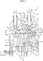
- the scroll compressor 1 is a hermetic type compressor, and is composed of a housing 11 having a sealed space therein, a scroll compression mechanism 12 that is disposed in the housing 11, and compresses a refrigerant taken in the sealed space, a rotating shaft 13 that transmits rotational force to the scroll compression mechanism 12, and an electric motor that revolves an orbit scroll 19 of the scroll compression mechanism 12 through the rotating shaft 13, as main components, as illustrated in Fig. 2 .
- the housing 11 has a bottom sealed by a lower cover, and includes a vertically elongated cylindrical intermediate cover 14 at an upper part of the lower cover.
- a discharge cover 15 and an upper cover 16 are provided at an upper part of the intermediate cover 14, and seal the housing 11, and a discharge chamber 17, to which compressed high pressure gas is discharged, is formed between this discharge cover 15 and the upper cover 16.
- the scroll compression mechanism 12 is incorporated in the housing 11, and the electric motor composed of a stator and a rotor is installed below the scroll compression mechanism.
- the stator is fixed and installed in the housing 11, so that the electric motor is incorporated, and the rotating shaft 13 is fixed to the rotor.
- the scroll compression mechanism 12 includes a fixed scroll 18 fixed and installed in the housing 11, the orbit scroll 19 that is slidably supported, and engages with the fixed scroll 18 to form compression chambers 20, and the like.
- a suction port that sucks a refrigerant is formed in a side surface of the housing 11 so as to communicate with the sealed space, and a discharge pipe 24 that communicates with the discharge chamber 17, and discharges compressed refrigerant gas is formed on a head top side of the upper cover 16.
- the scroll compression mechanism 12 sucks refrigerant gas sucked into the housing 11 through the suction pipe and the suction port, from a suction port 21 on an outer peripheral side opened to the inside of the housing 11, into the compression chambers 20, and compresses the sucked refrigerant gas.
- the compressed refrigerant gas is discharged into the discharge chamber 17 through a discharge port 22 provided at a central part of the fixed scroll 18, a refrigerant flow passage 30 provided in a block member 29, and a discharge port 23 provided in the discharge cover 15, and is further sent out to the outside of the compressor through the discharge pipe 24 provided in the upper cover 16 and communicated with the discharge chamber 17.
- a gas injection pipe 25 that introduces intermediate pressure refrigerant gas into the compression chambers 20 of the scroll compression mechanism 12 is connected to the discharge cover 15 through the injection flow passage 7.
- the gas injection pipe 25 is provided so as to penetrate the upper cover 16.
- An outer pipe 46 is installed around the gas injection pipe 25, and the gas injection pipe 25 is connected to the upper cover 16 through the outer pipe 46.
- the outer pipe 46 has one end connected to the gas injection pipe 25, and the other end opened to the inside of the discharge chamber 17.
- a refrigerant gas flow passage 31 that allows refrigerant gas to flow through is formed in the discharge cover 15, and an opening of the refrigerant gas flow passage 31 faces the block member 29.
- a refrigerant gas distribution flow passage 44 is formed in a surface on the discharge cover 15 of the block member 29.
- a refrigerant gas distribution flow passage 45 is formed in a surface on the block member 29 of the discharge cover 15.
- the refrigerant gas distribution flow passages 44, 45 are recessed grooves, and are annually formed.
- the refrigerant gas distribution flow passages 44, 45 are connected to a plurality of refrigerant gas flow passages 32 formed in the block member 29.
- the refrigerant gas that flows in the refrigerant gas flow passage 31 is supplied to the refrigerant gas distribution flow passages 44, 45. Then, the refrigerant gas supplied to the refrigerant gas distribution flow passages 44, 45 is distributed to the plurality of refrigerant gas flow passages 32 by the refrigerant gas distribution flow passages 44, 45.
- the refrigerant gas distribution flow passages 44, 45 are provided in the discharge cover 15 and the block member 29, so that it is possible to reduce the number of the gas injection pipes 25 that penetrate the housing 11. Only any one of the refrigerant gas distribution flow passages 44, 45 may be formed.
- the refrigerant gas is supplied to the compression chambers 20 through the gas injection pipe 25, the refrigerant gas flow passage 31 provided in the discharge cover 15, the refrigerant gas flow passages 32 provided in the block member 29, and gas injection ports 26 provided in the fixed scroll 18.
- the refrigerant gas can be supplied to the compression chambers 20 through the gas injection pipe 25.
- a liquid injection pipe 40 that introduces the refrigerant liquid into the compression chambers 20 of the scroll compression mechanism 12 is connected to the discharge cover 15 through the injection flow passage 8.
- the liquid injection pipe 40 is provided so as to penetrate the upper cover 16 and the discharge cover 15.
- a connector pipe 47 is installed around the liquid injection pipe 40, and an outer pipe 48 is installed around the connector pipe 47.
- the liquid injection pipe 40 is connected to the upper cover 16 through the outer pipe 48.
- the outer pipe 48 has one end connected to the liquid injection pipe 40, and the other end opened to the inside of the discharge chamber 17.
- the liquid injection pipe 40 is connected to the discharge cover 15 through the connector pipe 47.
- the connector pipe 47 has one end connected to the liquid injection pipe 40, and the other end opened to a low pressure space located below the discharge cover 15 while being connected to the discharge cover 15.
- the connector pipe 47 has one end connected to the discharge cover 15, and isolates a space on the discharge chamber 17 side from a low pressure space on the scroll compression mechanism 12 side. Consequently, the connector pipe 47 is connected to the discharge cover 15, and the liquid injection pipe 40 is disposed inside the connector pipe 47. Therefore, the space on the high pressure discharge chamber 17 side and the space on the low pressure scroll compression mechanism 12 side are isolated by the connector pipe 47, and therefore refrigerant leakage can be suppressed unlike a case in which the liquid injection pipe 40 is connected to the discharge cover 15 without providing the connector pipe 47.
- the refrigerant liquid is supplied to the compression chambers 20 through the liquid injection pipe 40, refrigerant liquid flow passages 41 provided in the block member 29, and liquid injection ports 42 provided in the fixed scroll 18. Consequently, the refrigerant liquid can be supplied to the compression chambers 20 through the liquid injection pipe 40.
- Switching between introduction of the refrigerant gas through the gas injection pipe 25 and introduction of the refrigerant liquid through the liquid injection pipe 40 is performed by opening and closing of an electromagnetic valve (not illustrated) on the basis of a signal from a controller, for example.
- the reed valve 27 defines the direction of the flow of the refrigerant only in one direction.
- the reed valve 27 is provided, so that the refrigerant flows from each compression chamber 20 to the discharge chamber 17 side.
- a retainer 33 that limits a movable range (opening upper limit) of the reed valve 27 is provided.
- the retainer 33 can regulate such that the reed valve 27 is not opened too widely.
- the retainer 33 is a member having high rigidity and unlikely to deform.
- the reed valve 27 is a member elongated in one direction, and has an end having, for example, an arc shape.
- the reed valve 27 has one end side fixed to the fixed scroll 18 by a bolt (not illustrated), and the other end side of the reed valve 27 capable of opening and closing with respect to the discharge port 22.
- the retainer 33 is also a member elongated in one direction similarly to the reed valve 27, and has one end side fixed by a bolt along with the reed valve 27.
- the fixed scroll 18 includes a substantially disk shaped end plate 18a, and a spiral wall body 18b erected on one side surface of the end plate 18a.
- the orbit scroll 19 includes a substantially disk shaped end plate 19a, and a spiral wall body 19b erected on one side surface of the end plate 19a.
- the respective spiral shapes of the wall bodies 18b, 19b are defined by using, for example, an involute curve or Archimedes' spiral curve.
- the discharge port 22, the gas injection ports 26, and the liquid injection ports 42 are formed in the end plate 18a so as to each penetrate in the plate thickness direction.
- the fixed scroll 18 and the orbit scroll 19 are engaged with each other such that the centers O 1 , O 2 thereof are separated by a turn radius p, and the phases of the wall bodies 18b, 19b are displaced by 180°, and are assembled such that slight clearances (tip clearances) in the height direction are present between tooth tips and tooth bottoms of the wall bodies 18b, 19b of the both scrolls 18, 19 at a normal temperature. Consequently, between the both scrolls 18, 19, a plurality of pairs of the compression chambers 20 formed so as to be surrounded by the end plates 18a, 19a and the wall bodies 18b, 19b are symmetrically formed with respect to the scroll centers.
- the orbit scroll 19 revolves around the fixed scroll 18 by a rotation prevention mechanism such as an oldham ring.
- the block member 29 is an example of a cover member, and is installed on a surface on the discharge cover 15 side of the fixed scroll 18 between the fixed scroll 18 and the discharge cover 15 by a bolt 35.
- the refrigerant flow passage 30 the plurality of refrigerant gas flow passages 32 that allows the refrigerant to flow through from the gas injection pipe 25
- the plurality of refrigerant liquid flow passages 41 that allow the refrigerant to flow through from the liquid injection pipe 40 are formed.
- the refrigerant gas flow passages 32 and the refrigerant liquid flow passages 41 are formed in the block member 29 so as to penetrate from a surface on the discharge cover 15 side (first surface) to a surface on the fixed scroll 18 side (second surface).
- recessed reed valve chambers 36, 43 are formed in the surface on the fixed scroll 18.
- the refrigerant gas that flows in the gas injection pipe 25 is supplied to the refrigerant gas flow passages 31, 32, and thereafter supplied to the reed valve chambers 36.
- the refrigerant liquid that flows in the liquid injection pipe 40 is supplied to the refrigerant liquid flow passages 41, and thereafter is supplied to the reed valve chambers 43.
- each reed valve chamber 36 the gas injection port 26 of the fixed scroll 18 is opened.
- the liquid injection port 42 of the fixed scroll 18 is opened.
- Reed valves 37 housed in the reed valve chambers 36, 43 are fixed by bolts 38.
- the reed valves 37 are sheet-like members, and are provided in outlets of the refrigerant gas flow passages 32 or the refrigerant liquid flow passages 41, and open and close the refrigerant gas flow passages 32 or the refrigerant liquid flow passages 41.
- the reed valves 37 each define the direction of the flow of the refrigerant only in one direction.
- Each reed valve 37 is provided, so that the refrigerant flows from the gas injection pipe 25 or the liquid injection pipe 40 to the compression chamber 20 side of the fixed scroll 18.
- the reed valve 37 provided in the outlet of each refrigerant gas flow passage 32 is an example of the first check valve
- the reed valve 37 provided in the outlet of each refrigerant liquid flow passage 41 is an example of the second check valve.
- a retainer 39 that limits the movable range (opening upper limit) of each reed valve 37 is provided in the movable direction of the reed valve 37.
- the reed valve 37 abuts on the retainer 39.
- each retainer 39 can regulate such that the reed valve 37 is not opened too widely.
- Each retainer 39 is a member having high rigidity and unlikely to deform.
- Each reed valve 37 is a member elongated in one direction, and has an end having, for example, an arc shape.
- Each reed valve 37 has one end side fixed to the block member 29 by the bolt 38, and the other end side of the reed valve 37 capable of opening and closing with respect to the refrigerant gas flow passage 32 or the refrigerant liquid flow passages 41.
- Each retainer 39 is also a member elongated in one direction similarly to the reed valve 37, and has one end side fixed to the reed valve 37 by the bolt 38.
- annular groove 49 is formed on a surface on the discharge cover 15 side of the block member 29.
- the groove 49 is formed around the refrigerant flow passage 30 formed in the block member 29 so as to surround the refrigerant flow passage 30.
- the refrigerant gas flow passages 32 are formed in the groove 49.
- An annular protrusion 50 is formed on a surface on the block member 29 side of the discharge cover 15. When the block member 29 and the discharge cover 15 are combined with each other, the protrusion 50 is in a state of being inserted into the groove 49 of the block member 29. In a portion where the protrusion 50 is formed, the refrigerant gas flow passage 31 is disposed.
- an end of the gas injection pipe 25 is connected to the discharge cover 15.
- the refrigerant gas flows through the gas injection pipe 25, and the refrigerant gas that flows in the gas injection pipe 25 is supplied to the refrigerant gas flow passages 31, 32, and thereafter supplied to the reed valve chambers 36, as illustrated by the hatched portions of Fig. 3 .
- the refrigerant gas is introduced into the compression chambers 20 of the scroll compression mechanism 12 through the gas injection ports 26 formed in the fixed scroll 18.
- An end of the liquid injection pipe 40 is connected to the block member 29.
- the refrigerant liquid flows through the liquid injection pipe 40, and the refrigerant liquid that flows in the liquid injection pipe 40 is supplied to the refrigerant liquid flow passages 41, and thereafter supplied to the reed valve chambers 43, as illustrated by the hatched portions of Fig. 4 .
- the refrigerant liquid is introduced into the compression chambers 20 of the scroll compression mechanism 12 through the liquid injection ports 42 formed in the fixed scroll 18.
- the housing 11 is assembled before the gas injection pipe 25 and the liquid injection pipe 40 are connected to internal components. That is, the components including the scroll compression mechanism 12, the electric motor, and the like are disposed in the housing 11, and welding connection of the intermediate cover 14 of the housing 11, and the discharge cover 15, and welding connection between the discharge cover 15 and the upper cover 16 are performed in a state in which the gas injection pipe 25 and the liquid injection pipe 40 are not connected.
- the gas injection pipe 25 is pressed into the discharge cover 15 from the outside of the upper cover 16, and the gas injection pipe 25 is connected to the discharge cover 15. Additionally, the outer pipe 46 is provided around the gas injection pipe 25, and the gas injection pipe 25 and the upper cover 16 are connected to each other.
- the liquid injection pipe 40 is pressed into the block member 29 from the outside of the upper cover 16, and the liquid injection pipe 40 is connected to the block member 29. Additionally, the connector pipe 47 and the outer pipe 48 are provided around the liquid injection pipe 40, the connector pipe 47 is connected to the discharge cover 15 and the liquid injection pipe 40, and the outer pipe 48 is connected to the upper cover 16 and the liquid injection pipe 40.
- the gas injection pipe 25 and the liquid injection pipe 40 are pressed in directions parallel to the axial direction of the rotating shaft 13.
- the gas injection pipe 25 and the liquid injection pipe 40 are pressed into the internal components, so that it is possible to complete connection between the gas injection pipe 25 and the liquid injection pipe 40, and the internal components.
- the housing 11 is first assembled before the gas injection pipe 25 and the liquid injection pipe 40 are connected to the internal components. Therefore, in a case in which welding around the housing 11 is performed, it is not necessary to cure the gas injection pipe 25 and the liquid injection pipe 40 to be provided so as to protrude from the housing 11. Therefore, welding work at the time of assembling the housing 11 is facilitated.
- the gas injection pipe 25 is connected to the discharge cover 15, and the refrigerant gas distribution flow passages 44, 45 are formed.
- the present invention is not limited to this example. That is, although not illustrated, while the liquid injection pipe 40 is not connected to the gas injection pipe 25, but connected to the discharge cover 15, a refrigerant liquid distribution flow passage may be annularly formed in the discharge cover 15 and/or the block member 29 similarly to the refrigerant gas distribution flow passages 44, 45 of the aforementioned embodiment, and refrigerant liquid may be distributed in the plurality of refrigerant liquid flow passages 41.
Landscapes
- Engineering & Computer Science (AREA)
- Mechanical Engineering (AREA)
- General Engineering & Computer Science (AREA)
- Rotary Pumps (AREA)
- Applications Or Details Of Rotary Compressors (AREA)
Abstract
Description
- The present invention relates to a compressor, and a method for manufacturing a compressor.
- Recently, in a refrigerating cycle such as a refrigerating device and an air conditioner, a refrigerant having low global warming potential (GWP) is used, so that the temperature of refrigerant gas discharged from a compressor (discharge gas temperature) tends to be increased. Some compressors, which are used under a high pressure ratio operation condition such as a refrigerating device for low temperature use, employ a liquid injection structure in which refrigerant liquid is injected during a compression stroke of the compressor, in order to reduce the discharge gas temperature.
- The following PTL 1 discloses a technology of providing a gas injection hole and a liquid injection hole in a scroll compressor, and properly cooling an electric motor and a compression part.
- [PTL 1] Japanese Unexamined Patent Application, Publication No.
H03-145589 - In the scroll compressor, a fixed scroll and an orbit scroll engage with each other, so that compression chambers are symmetrically formed. Accordingly, in the scroll compressor, a gas injection hole and a liquid injection hole provided in the fixed scroll are also desirably formed symmetrically in order to implement stable operation. Therefore, in a configuration in which a gas injection pipe or a liquid injection pipe for introducing a refrigerant into the compression mechanism are directly connected to the fixed scroll, it is necessary to have a structure in which the gas injection pipe or the liquid injection pipe is branched, and then the refrigerant is allowed to be introduced into the compression mechanism. Additionally, there is a problem of increasing the number of pipes that penetrate a sealed container of the compressor, increasing labor for processing of a penetration part, and increasing the number of portions where a countermeasure for refrigerant leakage is provided.
- The present invention has been made in view of such circumstances, an object of the present invention is to provide a compressor, and a method for manufacturing a compressor, in which assembly performance can be improved while a structure is simplified in a case in which a gas injection pipe and a liquid injection pipe are installed.
- A compressor according to a first aspect of the present invention includes: a housing; a scroll type compression mechanism housed in the housing and having a fixed scroll; a discharge cover provided with a discharge port through which a refrigerant compressed by the compression mechanism and discharged from the fixed scroll passes; a cover member installed between the discharge cover and the fixed scroll; and an injection pipe that has an end connected to the discharge cover and allows a refrigerant to flow therethrough, the refrigerant being to be introduced into a compression chamber of the compression mechanism, wherein the discharge cover or the cover member has a refrigerant distribution flow passage for distributing the refrigerant supplied from the injection pipe into a plurality of portions, and the cover member has a plurality of refrigerant flow passages that are formed so as to penetrate from a first surface on a side of the discharge cover to a second surface on a side of the fixed scroll, and allow the refrigerants distributed by the refrigerant distribution flow passage to flow through, and injection ports for introducing, to the compression chamber, the refrigerants which pass through the refrigerant flow passages are formed in the fixed scroll.
- According to this configuration, the refrigerant supplied from the injection pipe is distributed and supplied to the plurality of refrigerant flow passages formed in the cover member, in the refrigerant distribution flow passages formed on the discharge cover or the discharge cover side of the cover member. The refrigerant distribution flow passage is provided in the cover member, so that it is possible to reduce the number of the injection pipes that penetrate the housing.
- A compressor according to a second aspect of the present invention includes: a housing; a scroll type compression mechanism housed in the housing and having a fixed scroll; a discharge cover provided with a discharge port through which a refrigerant compressed by the compression mechanism and discharged from the fixed scroll passes; a cover member installed between the discharge cover and the fixed scroll; and a gas injection pipe that has an end connected to the discharge cover and allows gaseous refrigerant gas to flow therethrough, the gaseous refrigerant gas being to be introduced into a compression chamber of the compression mechanism, and a liquid injection pipe that has an end connected to the cover member and allows refrigerant liquid to flow therethrough, the refrigerant liquid being to be introduced into the compression chamber, wherein the discharge cover or the cover member has a refrigerant gas distribution flow passage for distributing the refrigerant gas supplied from the gas injection pipe into a plurality of portions, and the cover member has: a plurality of refrigerant gas flow passages that are formed so as to penetrate from a first surface on a side of the discharge cover to a second surface on a side of the fixed scroll, and allow the refrigerant gas distributed by the refrigerant gas distribution flow passage to flow through; and a refrigerant liquid flow passage that is formed so as to penetrate from the first surface to the second surface, and allows the refrigerant liquid supplied from the liquid injection pipe to flow through, and gas injection ports for introducing, to the compression chamber, the refrigerant gas which passes through the refrigerant flow passages, and a liquid injection port for introducing, to the compression chamber, the refrigerant liquid which passes through the refrigerant liquid flow passage are formed in the fixed scroll.
- According to this configuration, the refrigerant gas supplied from the gas injection pipe is distributed and supplied to the plurality of refrigerant gas flow passages formed in the cover member, in the refrigerant gas distribution flow passages formed on the discharge cover or the cover member. The refrigerant liquid supplied from the liquid injection pipe is supplied to the refrigerant liquid flow passage formed in the cover member. The refrigerant gas distribution flow passages are provided in the cover member, so that it is possible to reduce the number of the gas injection pipes that penetrate the housing.
- In the aforementioned second aspect, the cover member may have: a first check valve that is installed on the second surface, and prevents reverse flow of the refrigerant gas supplied from each of the refrigerant gas flow passages; and a second check valve that is installed on the second surface, and prevents reverse flow of the refrigerant liquid supplied from the refrigerant liquid flow passage.
- In the aforementioned second aspect, the compressor may further include: a discharge chamber formed between the housing and the discharge cover; and a connector pipe that is installed on a circumference of the liquid injection pipe, and houses the liquid injection pipe, wherein the connector pipe may have an end connected to the discharge cover, and isolate a space on a side of the discharge chamber from a space on a side of the compression mechanism.
- According to this configuration, the connector pipe is connected to the discharge cover, and the liquid injection pipe is disposed in the connector pipe. Therefore, the space on the high pressure discharge chamber side and the space on the low pressure compression mechanism side are isolated by the connector pipe, and therefore refrigerant leakage can be suppressed unlike a case in which the liquid injection pipe is connected to the discharge cover without providing the connector pipe.
- A method for manufacturing the compressor according to the third aspect of the present invention is a method for manufacturing the compressor of the first aspect, the method having the steps of: assembling the housing by welding connection; and pressing the injection pipe into the discharge cover from outside of the housing assembled by welding connection, in a direction parallel to a rotating shaft of the compressor.
- A method for manufacturing the compressor according to the fourth aspect of the present invention is a method for manufacturing the compressor of the second aspect, the method having the steps of: assembling the housing by welding connection; and pressing the gas injection pipe into the discharge cover from outside of the housing assembled by welding connection, in a direction parallel to a rotating shaft of the compressor, and pressing the liquid injection pipe into the cover member, in a direction parallel to the rotating shaft.
- According to the present invention, it is possible to improve assembly performance while a structure is simplified in a case in which a gas injection pipe and a liquid injection pipe are installed.
-
-
Fig. 1 is a configuration diagram illustrating a refrigerating cycle according to an embodiment of the present invention. -
Fig.2 is a partially longitudinal sectional view illustrating a principal part of a scroll compressor according to the embodiment of the present invention. -
Fig. 3 is a cross-sectional view illustrating the scroll compressor according to the embodiment of the present invention, and is a sectional view taken along the line A-A ofFig. 2 . Portions in which refrigerant gas flows are illustrated by hatched portions. -
Fig. 4 is a cross-sectional view illustrating a scroll compressor according to the embodiment of the present invention, and is a sectional view taken along the line A-A ofFig. 2 . Portions in which refrigerant liquid flows are illustrated by hatched portions. - Hereinafter, an embodiment according to the present invention will be described with reference to the drawings.
- As illustrated in
Fig. 1 , a refrigeratingcycle 10 includes a scroll compressor 1 that compresses a refrigerant (fluid), acondenser 2 that radiates heat of the compressed refrigerant to the outside, a first expansion valve 3 that decompresses the refrigerant which flows out from thecondenser 2, and is provided on a high pressure side, an economizer (gas-liquid separator) 4 that separates the decompressed refrigerant into a liquid refrigerant and a gas refrigerant, asecond expansion valve 5 that further decompresses a liquid refrigerant, and is provided on a low pressure side, an evaporator 6 that absorbs heat by the decompressed refrigerant, an injection flow passage 7 that guides the gas refrigerant from the economizer 4 to the scroll compressor 1, aninjection flow passage 8 that guides the liquid refrigerant from thecondenser 2 to the scroll compressor 1, and the like. - The scroll compressor 1 is a hermetic type compressor, and is composed of a
housing 11 having a sealed space therein, ascroll compression mechanism 12 that is disposed in thehousing 11, and compresses a refrigerant taken in the sealed space, a rotatingshaft 13 that transmits rotational force to thescroll compression mechanism 12, and an electric motor that revolves anorbit scroll 19 of thescroll compression mechanism 12 through the rotatingshaft 13, as main components, as illustrated inFig. 2 . - The
housing 11 has a bottom sealed by a lower cover, and includes a vertically elongated cylindricalintermediate cover 14 at an upper part of the lower cover. Adischarge cover 15 and anupper cover 16 are provided at an upper part of theintermediate cover 14, and seal thehousing 11, and adischarge chamber 17, to which compressed high pressure gas is discharged, is formed between thisdischarge cover 15 and theupper cover 16. - The
scroll compression mechanism 12 is incorporated in thehousing 11, and the electric motor composed of a stator and a rotor is installed below the scroll compression mechanism. The stator is fixed and installed in thehousing 11, so that the electric motor is incorporated, and the rotatingshaft 13 is fixed to the rotor. - The
scroll compression mechanism 12 includes afixed scroll 18 fixed and installed in thehousing 11, theorbit scroll 19 that is slidably supported, and engages with thefixed scroll 18 to formcompression chambers 20, and the like. - A suction port that sucks a refrigerant is formed in a side surface of the
housing 11 so as to communicate with the sealed space, and adischarge pipe 24 that communicates with thedischarge chamber 17, and discharges compressed refrigerant gas is formed on a head top side of theupper cover 16. - The
scroll compression mechanism 12 sucks refrigerant gas sucked into thehousing 11 through the suction pipe and the suction port, from asuction port 21 on an outer peripheral side opened to the inside of thehousing 11, into thecompression chambers 20, and compresses the sucked refrigerant gas. The compressed refrigerant gas is discharged into thedischarge chamber 17 through adischarge port 22 provided at a central part of thefixed scroll 18, arefrigerant flow passage 30 provided in ablock member 29, and adischarge port 23 provided in thedischarge cover 15, and is further sent out to the outside of the compressor through thedischarge pipe 24 provided in theupper cover 16 and communicated with thedischarge chamber 17. - A
gas injection pipe 25 that introduces intermediate pressure refrigerant gas into thecompression chambers 20 of thescroll compression mechanism 12 is connected to thedischarge cover 15 through the injection flow passage 7. Thegas injection pipe 25 is provided so as to penetrate theupper cover 16. Anouter pipe 46 is installed around thegas injection pipe 25, and thegas injection pipe 25 is connected to theupper cover 16 through theouter pipe 46. Theouter pipe 46 has one end connected to thegas injection pipe 25, and the other end opened to the inside of thedischarge chamber 17. - A refrigerant
gas flow passage 31 that allows refrigerant gas to flow through is formed in thedischarge cover 15, and an opening of the refrigerantgas flow passage 31 faces theblock member 29. A refrigerant gasdistribution flow passage 44 is formed in a surface on thedischarge cover 15 of theblock member 29. A refrigerant gasdistribution flow passage 45 is formed in a surface on theblock member 29 of thedischarge cover 15. The refrigerant gasdistribution flow passages distribution flow passages gas flow passages 32 formed in theblock member 29. - The refrigerant gas that flows in the refrigerant
gas flow passage 31 is supplied to the refrigerant gasdistribution flow passages distribution flow passages gas flow passages 32 by the refrigerant gasdistribution flow passages distribution flow passages discharge cover 15 and theblock member 29, so that it is possible to reduce the number of thegas injection pipes 25 that penetrate thehousing 11. Only any one of the refrigerant gasdistribution flow passages - The refrigerant gas is supplied to the
compression chambers 20 through thegas injection pipe 25, the refrigerantgas flow passage 31 provided in thedischarge cover 15, the refrigerantgas flow passages 32 provided in theblock member 29, andgas injection ports 26 provided in thefixed scroll 18. The refrigerant gas can be supplied to thecompression chambers 20 through thegas injection pipe 25. - Furthermore, a
liquid injection pipe 40 that introduces the refrigerant liquid into thecompression chambers 20 of thescroll compression mechanism 12 is connected to thedischarge cover 15 through theinjection flow passage 8. Theliquid injection pipe 40 is provided so as to penetrate theupper cover 16 and thedischarge cover 15. Aconnector pipe 47 is installed around theliquid injection pipe 40, and anouter pipe 48 is installed around theconnector pipe 47. - The
liquid injection pipe 40 is connected to theupper cover 16 through theouter pipe 48. Theouter pipe 48 has one end connected to theliquid injection pipe 40, and the other end opened to the inside of thedischarge chamber 17. Theliquid injection pipe 40 is connected to thedischarge cover 15 through theconnector pipe 47. Theconnector pipe 47 has one end connected to theliquid injection pipe 40, and the other end opened to a low pressure space located below thedischarge cover 15 while being connected to thedischarge cover 15. - The
connector pipe 47 has one end connected to thedischarge cover 15, and isolates a space on thedischarge chamber 17 side from a low pressure space on thescroll compression mechanism 12 side. Consequently, theconnector pipe 47 is connected to thedischarge cover 15, and theliquid injection pipe 40 is disposed inside theconnector pipe 47. Therefore, the space on the highpressure discharge chamber 17 side and the space on the low pressurescroll compression mechanism 12 side are isolated by theconnector pipe 47, and therefore refrigerant leakage can be suppressed unlike a case in which theliquid injection pipe 40 is connected to thedischarge cover 15 without providing theconnector pipe 47. - The refrigerant liquid is supplied to the
compression chambers 20 through theliquid injection pipe 40, refrigerantliquid flow passages 41 provided in theblock member 29, andliquid injection ports 42 provided in the fixedscroll 18. Consequently, the refrigerant liquid can be supplied to thecompression chambers 20 through theliquid injection pipe 40. - Switching between introduction of the refrigerant gas through the
gas injection pipe 25 and introduction of the refrigerant liquid through theliquid injection pipe 40 is performed by opening and closing of an electromagnetic valve (not illustrated) on the basis of a signal from a controller, for example. - A
reed valve 27, which is a thin plate member, is provided in an outlet of thedischarge port 22, and opens and closes thedischarge port 22. Thereed valve 27 defines the direction of the flow of the refrigerant only in one direction. Thereed valve 27 is provided, so that the refrigerant flows from eachcompression chamber 20 to thedischarge chamber 17 side. - In the movable direction of the
reed valve 27, aretainer 33 that limits a movable range (opening upper limit) of thereed valve 27 is provided. When thereed valve 27 is opened, thereed valve 27 abuts on theretainer 33. Thus, theretainer 33 can regulate such that thereed valve 27 is not opened too widely. Theretainer 33 is a member having high rigidity and unlikely to deform. - The
reed valve 27 is a member elongated in one direction, and has an end having, for example, an arc shape. Thereed valve 27 has one end side fixed to the fixedscroll 18 by a bolt (not illustrated), and the other end side of thereed valve 27 capable of opening and closing with respect to thedischarge port 22. Theretainer 33 is also a member elongated in one direction similarly to thereed valve 27, and has one end side fixed by a bolt along with thereed valve 27. - As illustrated in
Fig. 2 , the fixedscroll 18 includes a substantially disk shapedend plate 18a, and aspiral wall body 18b erected on one side surface of theend plate 18a. As illustrated inFig. 2 , theorbit scroll 19 includes a substantially disk shapedend plate 19a, and aspiral wall body 19b erected on one side surface of theend plate 19a. The respective spiral shapes of thewall bodies scroll 18, thedischarge port 22, thegas injection ports 26, and theliquid injection ports 42 are formed in theend plate 18a so as to each penetrate in the plate thickness direction. - The fixed
scroll 18 and theorbit scroll 19 are engaged with each other such that the centers O1, O2 thereof are separated by a turn radius p, and the phases of thewall bodies wall bodies compression chambers 20 formed so as to be surrounded by theend plates wall bodies orbit scroll 19 revolves around the fixedscroll 18 by a rotation prevention mechanism such as an oldham ring. - The
block member 29 is an example of a cover member, and is installed on a surface on thedischarge cover 15 side of the fixedscroll 18 between the fixedscroll 18 and thedischarge cover 15 by abolt 35. - In the
block member 29, therefrigerant flow passage 30, the plurality of refrigerantgas flow passages 32 that allows the refrigerant to flow through from thegas injection pipe 25, the plurality of refrigerantliquid flow passages 41 that allow the refrigerant to flow through from theliquid injection pipe 40 are formed. The refrigerantgas flow passages 32 and the refrigerantliquid flow passages 41 are formed in theblock member 29 so as to penetrate from a surface on thedischarge cover 15 side (first surface) to a surface on the fixedscroll 18 side (second surface). - In the
block member 29, recessedreed valve chambers scroll 18. As illustrated by hatched portions ofFig. 3 , the refrigerant gas that flows in thegas injection pipe 25 is supplied to the refrigerantgas flow passages reed valve chambers 36. As illustrated by hatched portions ofFig. 4 , the refrigerant liquid that flows in theliquid injection pipe 40 is supplied to the refrigerantliquid flow passages 41, and thereafter is supplied to thereed valve chambers 43. - In each
reed valve chamber 36, thegas injection port 26 of the fixedscroll 18 is opened. In eachreed valve chamber 43, theliquid injection port 42 of the fixedscroll 18 is opened.Reed valves 37 housed in thereed valve chambers bolts 38. - The
reed valves 37 are sheet-like members, and are provided in outlets of the refrigerantgas flow passages 32 or the refrigerantliquid flow passages 41, and open and close the refrigerantgas flow passages 32 or the refrigerantliquid flow passages 41. Thereed valves 37 each define the direction of the flow of the refrigerant only in one direction. Eachreed valve 37 is provided, so that the refrigerant flows from thegas injection pipe 25 or theliquid injection pipe 40 to thecompression chamber 20 side of the fixedscroll 18. Thereed valve 37 provided in the outlet of each refrigerantgas flow passage 32 is an example of the first check valve, and thereed valve 37 provided in the outlet of each refrigerantliquid flow passage 41 is an example of the second check valve. - A
retainer 39 that limits the movable range (opening upper limit) of eachreed valve 37 is provided in the movable direction of thereed valve 37. When eachreed valve 37 is opened, thereed valve 37 abuts on theretainer 39. Thus, eachretainer 39 can regulate such that thereed valve 37 is not opened too widely. Eachretainer 39 is a member having high rigidity and unlikely to deform. - Each
reed valve 37 is a member elongated in one direction, and has an end having, for example, an arc shape. Eachreed valve 37 has one end side fixed to theblock member 29 by thebolt 38, and the other end side of thereed valve 37 capable of opening and closing with respect to the refrigerantgas flow passage 32 or the refrigerantliquid flow passages 41. Eachretainer 39 is also a member elongated in one direction similarly to thereed valve 37, and has one end side fixed to thereed valve 37 by thebolt 38. - As illustrated in
Fig. 2 , anannular groove 49 is formed on a surface on thedischarge cover 15 side of theblock member 29. Thegroove 49 is formed around therefrigerant flow passage 30 formed in theblock member 29 so as to surround therefrigerant flow passage 30. The refrigerantgas flow passages 32 are formed in thegroove 49. Anannular protrusion 50 is formed on a surface on theblock member 29 side of thedischarge cover 15. When theblock member 29 and thedischarge cover 15 are combined with each other, theprotrusion 50 is in a state of being inserted into thegroove 49 of theblock member 29. In a portion where theprotrusion 50 is formed, the refrigerantgas flow passage 31 is disposed. In a state in which thegroove 49 and theprotrusion 50 are combined with each other, a clearance between thegroove 49 and theprotrusion 50 is reduced, and therefore O-rings 51 are installed on an inner wall surfaces of thegroove 49. Consequently, at a portion where thegroove 49 and theprotrusion 50 are combined with each other, it is possible to reliably isolate the high pressure side from the low pressure side. - As described above, an end of the
gas injection pipe 25 is connected to thedischarge cover 15. In a case in which refrigerant gas is introduced into thecompression chambers 20, the refrigerant gas flows through thegas injection pipe 25, and the refrigerant gas that flows in thegas injection pipe 25 is supplied to the refrigerantgas flow passages reed valve chambers 36, as illustrated by the hatched portions ofFig. 3 . Then, the refrigerant gas is introduced into thecompression chambers 20 of thescroll compression mechanism 12 through thegas injection ports 26 formed in the fixedscroll 18. - An end of the
liquid injection pipe 40 is connected to theblock member 29. In a case in which refrigerant liquid is introduced into thecompression chambers 20, the refrigerant liquid flows through theliquid injection pipe 40, and the refrigerant liquid that flows in theliquid injection pipe 40 is supplied to the refrigerantliquid flow passages 41, and thereafter supplied to thereed valve chambers 43, as illustrated by the hatched portions ofFig. 4 . Then, the refrigerant liquid is introduced into thecompression chambers 20 of thescroll compression mechanism 12 through theliquid injection ports 42 formed in the fixedscroll 18. - In a case in which the aforementioned scroll compressor 1 is assembled, the
housing 11 is assembled before thegas injection pipe 25 and theliquid injection pipe 40 are connected to internal components. That is, the components including thescroll compression mechanism 12, the electric motor, and the like are disposed in thehousing 11, and welding connection of theintermediate cover 14 of thehousing 11, and thedischarge cover 15, and welding connection between thedischarge cover 15 and theupper cover 16 are performed in a state in which thegas injection pipe 25 and theliquid injection pipe 40 are not connected. - Thereafter, the
gas injection pipe 25 is pressed into the discharge cover 15 from the outside of theupper cover 16, and thegas injection pipe 25 is connected to thedischarge cover 15. Additionally, theouter pipe 46 is provided around thegas injection pipe 25, and thegas injection pipe 25 and theupper cover 16 are connected to each other. - The
liquid injection pipe 40 is pressed into theblock member 29 from the outside of theupper cover 16, and theliquid injection pipe 40 is connected to theblock member 29. Additionally, theconnector pipe 47 and theouter pipe 48 are provided around theliquid injection pipe 40, theconnector pipe 47 is connected to thedischarge cover 15 and theliquid injection pipe 40, and theouter pipe 48 is connected to theupper cover 16 and theliquid injection pipe 40. Thegas injection pipe 25 and theliquid injection pipe 40 are pressed in directions parallel to the axial direction of therotating shaft 13. - According to this embodiment, the
gas injection pipe 25 and theliquid injection pipe 40 are pressed into the internal components, so that it is possible to complete connection between thegas injection pipe 25 and theliquid injection pipe 40, and the internal components. In a case in which the scroll compressor 1 is assembled, thehousing 11 is first assembled before thegas injection pipe 25 and theliquid injection pipe 40 are connected to the internal components. Therefore, in a case in which welding around thehousing 11 is performed, it is not necessary to cure thegas injection pipe 25 and theliquid injection pipe 40 to be provided so as to protrude from thehousing 11. Therefore, welding work at the time of assembling thehousing 11 is facilitated. - In the aforementioned embodiment, the
gas injection pipe 25 is connected to thedischarge cover 15, and the refrigerant gasdistribution flow passages liquid injection pipe 40 is not connected to thegas injection pipe 25, but connected to thedischarge cover 15, a refrigerant liquid distribution flow passage may be annularly formed in thedischarge cover 15 and/or theblock member 29 similarly to the refrigerant gasdistribution flow passages liquid flow passages 41. -
- 1 scroll compressor
- 2 condenser
- 3 first expansion valve
- 4 economizer
- 5 second expansion valve
- 6 evaporator
- 7, 8 injection flow passage
- 10 refrigerating cycle
- 11 housing
- 12 scroll compression mechanism
- 13 rotating shaft
- 14 intermediate cover
- 15 discharge cover
- 16 upper cover
- 17 discharge chamber
- 18 fixed scroll
- 19 orbit scroll
- 20 compression chamber
- 21 suction port
- 22 discharge port
- 23 discharge port
- 24 discharge pipe
- 25 gas injection pipe (injection pipe)
- 26 gas injection port (injection port)
- 27 reed valve
- 29 block member (cover member)
- 30 refrigerant flow passage
- 31 refrigerant gas flow passage
- 32 refrigerant gas flow passage (refrigerant flow passage)
- 33, 39 retainer
- 35, 38 bolt
- 36, 43 reed valve chamber
- 37 reed valve (first check valve, second check valve)
- 40 liquid injection pipe (injection pipe)
- 41 refrigerant liquid flow passage (refrigerant flow passage)
- 42 liquid injection port (injection ports)
- 44, 45 refrigerant gas distribution flow passage (refrigerant distribution flow passage)
- 46, 48 outer pipe
- 47 connector pipe
- 49 groove
- 50 protrusion
- 51 O-ring
Claims (6)
- A compressor (1) comprising:a housing (11);a scroll type compression mechanism (12) housed in the housing (11) and having a fixed scroll (18);a discharge cover (15) provided with a discharge port (23) through which a refrigerant compressed by the compression mechanism (12) and discharged from the fixed scroll (18) passes;a cover member (29) installed between the discharge cover (15) and the fixed scroll (18); andat least one injection pipe (25, 40), each having an end connected to the discharge cover (15) and configured to allow a refrigerant to flow therethrough, the refrigerant being to be introduced into a compression chamber (20) of the compression mechanism (12), whereinthe discharge cover (15) or the cover member (29) has a refrigerant distribution flow passage (45, 44) for distributing the refrigerant supplied from the injection pipe (25, 40) into a plurality of portions, andthe cover member (29) has a plurality of refrigerant flow passages (32, 41) that are formed so as to penetrate from a first surface on a side of the discharge cover (15) to a second surface on a side of the fixed scroll (18), and allow the refrigerants distributed by the refrigerant distribution flow passage (45, 44) to flow through, andinjection ports (26, 42) for introducing, to the compression chamber (20), the refrigerants which pass through the refrigerant flow passages (32, 41) are formed in the fixed scroll (18).
- A compressor (1) according to claim 1, wherein:
the at least one injection pipe (25, 40) comprises:a gas injection pipe (25) that has an end connected to the discharge cover (15) and is configured to allow gaseous refrigerant gas to flow therethrough, the gaseous refrigerant gas being to be introduced into a compression chamber (20) of the compression mechanism (12), anda liquid injection pipe (40) that has an end connected to the cover member (29) and is configured to allow refrigerant liquid to flow therethrough, the refrigerant liquid being to be introduced into the compression chamber (20);the refrigerant distribution flow passage (45, 44) is a refrigerant gas distribution flow passage (45, 44) for distributing the refrigerant gas supplied from the gas injection pipe (25) into a plurality of portions;the plurality of refrigerant flow passages (32, 41) comprises:a plurality of refrigerant gas flow passages (32) that are formed so as to penetrate from a first surface on a side of the discharge cover (15) to a second surface on a side of the fixed scroll (18), and allow the refrigerant gas distributed by the refrigerant gas distribution flow passage (45, 44) to flow through, anda refrigerant liquid flow passage (41) that is formed so as to penetrate from the first surface to the second surface, and allow the refrigerant liquid supplied from the liquid injection pipe (40) to flow through; andthe injection ports (26, 42) comprise:gas injection ports (26) for introducing, to the compression chamber (20), the refrigerant gas which passes through the refrigerant flow passages (32), anda liquid injection port (42) for introducing, to the compression chamber (20), the refrigerant liquid which passes through the refrigerant liquid flow passage (41). - The compressor (1) according to claim 2, wherein
the cover member (29) has:a first check valve (37) that is installed on the second surface, and prevents reverse flow of the refrigerant gas supplied from each of the refrigerant gas flow passages (32); anda second check valve (37) that is installed on the second surface, and prevents reverse flow of the refrigerant liquid supplied from the refrigerant liquid flow passage (41). - The compressor (1) according to claim 2 or 3, further comprising:a discharge chamber (17) formed between the housing (11) and the discharge cover (15); anda connector pipe (47) that is installed on a circumference of the liquid injection pipe (40), and houses the liquid injection pipe (40), whereinthe connector pipe (47) has an end connected to the discharge cover (15), and isolates a space on a side of the discharge chamber (17) from a space on a side of the compression mechanism (12).
- A method for manufacturing the compressor (1) according to claim 1, the method comprising the steps of:assembling the housing (11) by welding connection; andpressing the injection pipe (25, 40) into the discharge cover (15) from outside of the housing (11) assembled by welding connection, in a direction parallel to a rotating shaft (13) of the compressor (1).
- A method for manufacturing the compressor (1) according to any one of claims 2 to 4, the method comprising the steps of:assembling the housing (11) by welding connection; andpressing the gas injection pipe (25) into the discharge cover (15) from outside of the housing (11) assembled by welding connection, in a direction parallel to a rotating shaft (13) of the compressor (1), and pressing the liquid injection pipe (40) into the cover member (29), in a direction parallel to the rotating shaft (13).
Applications Claiming Priority (1)
| Application Number | Priority Date | Filing Date | Title |
|---|---|---|---|
| JP2018107595A JP7123636B2 (en) | 2018-06-05 | 2018-06-05 | Compressor and method for manufacturing compressor |
Publications (2)
| Publication Number | Publication Date |
|---|---|
| EP3578823A1 true EP3578823A1 (en) | 2019-12-11 |
| EP3578823B1 EP3578823B1 (en) | 2021-03-03 |
Family
ID=66751925
Family Applications (1)
| Application Number | Title | Priority Date | Filing Date |
|---|---|---|---|
| EP19177971.9A Active EP3578823B1 (en) | 2018-06-05 | 2019-06-03 | Compressor and method for manufacturing compressor |
Country Status (2)
| Country | Link |
|---|---|
| EP (1) | EP3578823B1 (en) |
| JP (1) | JP7123636B2 (en) |
Cited By (2)
| Publication number | Priority date | Publication date | Assignee | Title |
|---|---|---|---|---|
| EP4325056A3 (en) * | 2022-08-16 | 2024-06-19 | BITZER Kühlmaschinenbau GmbH | Scroll machine and refrigeration system |
| US12345256B2 (en) * | 2021-08-04 | 2025-07-01 | Daikin Industries, Ltd. | Scroll compressor |
Families Citing this family (5)
| Publication number | Priority date | Publication date | Assignee | Title |
|---|---|---|---|---|
| JP7203796B2 (en) | 2020-09-30 | 2023-01-13 | 三菱重工サーマルシステムズ株式会社 | scroll compressor |
| JP7225178B2 (en) * | 2020-10-06 | 2023-02-20 | 三菱重工サーマルシステムズ株式会社 | Heat source machine and its control method |
| DE102022120678A1 (en) | 2022-08-16 | 2024-02-22 | Bitzer Kühlmaschinenbau Gmbh | Scroll machine with injection and refrigeration systemScroll machine with injection and refrigeration system |
| KR20240035305A (en) * | 2022-09-08 | 2024-03-15 | 한온시스템 주식회사 | Scroll compressor |
| JP7804781B2 (en) * | 2022-09-29 | 2026-01-22 | ボッシュホームコンフォートジャパン株式会社 | Scroll compressor and air conditioner |
Citations (2)
| Publication number | Priority date | Publication date | Assignee | Title |
|---|---|---|---|---|
| JPH03145589A (en) | 1989-10-30 | 1991-06-20 | Hitachi Ltd | Scroll type refrigeration equipment for low temperature |
| WO2017150602A1 (en) * | 2016-03-04 | 2017-09-08 | 三菱重工サーマルシステムズ株式会社 | Compressor |
Family Cites Families (3)
| Publication number | Priority date | Publication date | Assignee | Title |
|---|---|---|---|---|
| JPH11107949A (en) * | 1997-10-06 | 1999-04-20 | Matsushita Electric Ind Co Ltd | Scroll compressor |
| JP5314326B2 (en) | 2008-05-30 | 2013-10-16 | 三菱重工業株式会社 | Refrigerant compressor |
| JP6460595B2 (en) | 2014-12-04 | 2019-01-30 | 株式会社デンソー | Compressor |
-
2018
- 2018-06-05 JP JP2018107595A patent/JP7123636B2/en active Active
-
2019
- 2019-06-03 EP EP19177971.9A patent/EP3578823B1/en active Active
Patent Citations (2)
| Publication number | Priority date | Publication date | Assignee | Title |
|---|---|---|---|---|
| JPH03145589A (en) | 1989-10-30 | 1991-06-20 | Hitachi Ltd | Scroll type refrigeration equipment for low temperature |
| WO2017150602A1 (en) * | 2016-03-04 | 2017-09-08 | 三菱重工サーマルシステムズ株式会社 | Compressor |
Cited By (3)
| Publication number | Priority date | Publication date | Assignee | Title |
|---|---|---|---|---|
| US12345256B2 (en) * | 2021-08-04 | 2025-07-01 | Daikin Industries, Ltd. | Scroll compressor |
| EP4325056A3 (en) * | 2022-08-16 | 2024-06-19 | BITZER Kühlmaschinenbau GmbH | Scroll machine and refrigeration system |
| US12510073B2 (en) | 2022-08-16 | 2025-12-30 | Bitzer Kuehlmaschinenbau Gmbh | Refrigeration system with a scroll machine having a plate inserted in a base of the scroll machine |
Also Published As
| Publication number | Publication date |
|---|---|
| JP7123636B2 (en) | 2022-08-23 |
| EP3578823B1 (en) | 2021-03-03 |
| JP2019210867A (en) | 2019-12-12 |
Similar Documents
| Publication | Publication Date | Title |
|---|---|---|
| EP3578823B1 (en) | Compressor and method for manufacturing compressor | |
| US10962008B2 (en) | Variable volume ratio compressor | |
| CN103415704B (en) | Swirl type cold compressor | |
| KR101192649B1 (en) | Compressor having output adjustment assembly including piston actuation | |
| CN108953141B (en) | Positive displacement machine according to the screw principle, method for operating a positive displacement machine, vehicle air conditioning system and vehicle | |
| US10221852B2 (en) | Multi stage scroll vacuum pumps and related scroll devices | |
| EP1382854A2 (en) | Dual volume-ratio scroll machine | |
| US20180258933A1 (en) | Positive-displacement machine according to the spiral principle, method for operating a positive-displacement machine, positive-displacement spiral, vehicle air-conditioning system and vehicle | |
| US10393117B2 (en) | Scroll compressor | |
| CN101939548B (en) | Compressor and freezer | |
| EP3572671A1 (en) | Compressor with an injection port and check valve. | |
| US9695823B2 (en) | Compressor with unloader counterweight assembly | |
| US9689388B2 (en) | Scroll compressor | |
| KR101800512B1 (en) | Motor-driven compressor | |
| EP2549109B1 (en) | Scroll compressor | |
| EP2116726B1 (en) | Scroll compressor and air conditioner | |
| EP3751143B1 (en) | Scroll fluid machine | |
| US9581161B2 (en) | Compressor with service valve assembly | |
| US12000396B2 (en) | Scroll compressor | |
| US12320356B2 (en) | Scroll compressor | |
| KR102770848B1 (en) | Scroll compressor | |
| US12523222B2 (en) | Scroll compressor with injection valve assembly | |
| JP7154868B2 (en) | compressor | |
| WO2019163537A1 (en) | Scroll fluid machine | |
| EP4170172A1 (en) | Scroll compressor |
Legal Events
| Date | Code | Title | Description |
|---|---|---|---|
| PUAI | Public reference made under article 153(3) epc to a published international application that has entered the european phase |
Free format text: ORIGINAL CODE: 0009012 |
|
| STAA | Information on the status of an ep patent application or granted ep patent |
Free format text: STATUS: THE APPLICATION HAS BEEN PUBLISHED |
|
| AK | Designated contracting states |
Kind code of ref document: A1 Designated state(s): AL AT BE BG CH CY CZ DE DK EE ES FI FR GB GR HR HU IE IS IT LI LT LU LV MC MK MT NL NO PL PT RO RS SE SI SK SM TR |
|
| AX | Request for extension of the european patent |
Extension state: BA ME |
|
| STAA | Information on the status of an ep patent application or granted ep patent |
Free format text: STATUS: REQUEST FOR EXAMINATION WAS MADE |
|
| 17P | Request for examination filed |
Effective date: 20200609 |
|
| RBV | Designated contracting states (corrected) |
Designated state(s): AL AT BE BG CH CY CZ DE DK EE ES FI FR GB GR HR HU IE IS IT LI LT LU LV MC MK MT NL NO PL PT RO RS SE SI SK SM TR |
|
| GRAP | Despatch of communication of intention to grant a patent |
Free format text: ORIGINAL CODE: EPIDOSNIGR1 |
|
| STAA | Information on the status of an ep patent application or granted ep patent |
Free format text: STATUS: GRANT OF PATENT IS INTENDED |
|
| RIC1 | Information provided on ipc code assigned before grant |
Ipc: F04C 29/04 20060101ALI20200827BHEP Ipc: F04C 29/12 20060101ALI20200827BHEP Ipc: F04C 18/02 20060101AFI20200827BHEP Ipc: F04C 23/00 20060101ALI20200827BHEP |
|
| INTG | Intention to grant announced |
Effective date: 20200925 |
|
| GRAS | Grant fee paid |
Free format text: ORIGINAL CODE: EPIDOSNIGR3 |
|
| GRAA | (expected) grant |
Free format text: ORIGINAL CODE: 0009210 |
|
| STAA | Information on the status of an ep patent application or granted ep patent |
Free format text: STATUS: THE PATENT HAS BEEN GRANTED |
|
| AK | Designated contracting states |
Kind code of ref document: B1 Designated state(s): AL AT BE BG CH CY CZ DE DK EE ES FI FR GB GR HR HU IE IS IT LI LT LU LV MC MK MT NL NO PL PT RO RS SE SI SK SM TR |
|
| REG | Reference to a national code |
Ref country code: GB Ref legal event code: FG4D |
|
| REG | Reference to a national code |
Ref country code: CH Ref legal event code: EP Ref country code: AT Ref legal event code: REF Ref document number: 1367491 Country of ref document: AT Kind code of ref document: T Effective date: 20210315 |
|
| REG | Reference to a national code |
Ref country code: DE Ref legal event code: R096 Ref document number: 602019002894 Country of ref document: DE |
|
| REG | Reference to a national code |
Ref country code: IE Ref legal event code: FG4D |
|
| REG | Reference to a national code |
Ref country code: SE Ref legal event code: TRGR |
|
| REG | Reference to a national code |
Ref country code: LT Ref legal event code: MG9D |
|
| PG25 | Lapsed in a contracting state [announced via postgrant information from national office to epo] |
Ref country code: FI Free format text: LAPSE BECAUSE OF FAILURE TO SUBMIT A TRANSLATION OF THE DESCRIPTION OR TO PAY THE FEE WITHIN THE PRESCRIBED TIME-LIMIT Effective date: 20210303 Ref country code: GR Free format text: LAPSE BECAUSE OF FAILURE TO SUBMIT A TRANSLATION OF THE DESCRIPTION OR TO PAY THE FEE WITHIN THE PRESCRIBED TIME-LIMIT Effective date: 20210604 Ref country code: HR Free format text: LAPSE BECAUSE OF FAILURE TO SUBMIT A TRANSLATION OF THE DESCRIPTION OR TO PAY THE FEE WITHIN THE PRESCRIBED TIME-LIMIT Effective date: 20210303 Ref country code: BG Free format text: LAPSE BECAUSE OF FAILURE TO SUBMIT A TRANSLATION OF THE DESCRIPTION OR TO PAY THE FEE WITHIN THE PRESCRIBED TIME-LIMIT Effective date: 20210603 Ref country code: NO Free format text: LAPSE BECAUSE OF FAILURE TO SUBMIT A TRANSLATION OF THE DESCRIPTION OR TO PAY THE FEE WITHIN THE PRESCRIBED TIME-LIMIT Effective date: 20210603 Ref country code: LT Free format text: LAPSE BECAUSE OF FAILURE TO SUBMIT A TRANSLATION OF THE DESCRIPTION OR TO PAY THE FEE WITHIN THE PRESCRIBED TIME-LIMIT Effective date: 20210303 |
|
| REG | Reference to a national code |
Ref country code: NL Ref legal event code: MP Effective date: 20210303 |
|
| REG | Reference to a national code |
Ref country code: AT Ref legal event code: MK05 Ref document number: 1367491 Country of ref document: AT Kind code of ref document: T Effective date: 20210303 |
|
| PG25 | Lapsed in a contracting state [announced via postgrant information from national office to epo] |
Ref country code: PL Free format text: LAPSE BECAUSE OF FAILURE TO SUBMIT A TRANSLATION OF THE DESCRIPTION OR TO PAY THE FEE WITHIN THE PRESCRIBED TIME-LIMIT Effective date: 20210303 Ref country code: LV Free format text: LAPSE BECAUSE OF FAILURE TO SUBMIT A TRANSLATION OF THE DESCRIPTION OR TO PAY THE FEE WITHIN THE PRESCRIBED TIME-LIMIT Effective date: 20210303 Ref country code: RS Free format text: LAPSE BECAUSE OF FAILURE TO SUBMIT A TRANSLATION OF THE DESCRIPTION OR TO PAY THE FEE WITHIN THE PRESCRIBED TIME-LIMIT Effective date: 20210303 |
|
| PG25 | Lapsed in a contracting state [announced via postgrant information from national office to epo] |
Ref country code: NL Free format text: LAPSE BECAUSE OF FAILURE TO SUBMIT A TRANSLATION OF THE DESCRIPTION OR TO PAY THE FEE WITHIN THE PRESCRIBED TIME-LIMIT Effective date: 20210303 |
|
| PG25 | Lapsed in a contracting state [announced via postgrant information from national office to epo] |
Ref country code: CZ Free format text: LAPSE BECAUSE OF FAILURE TO SUBMIT A TRANSLATION OF THE DESCRIPTION OR TO PAY THE FEE WITHIN THE PRESCRIBED TIME-LIMIT Effective date: 20210303 Ref country code: EE Free format text: LAPSE BECAUSE OF FAILURE TO SUBMIT A TRANSLATION OF THE DESCRIPTION OR TO PAY THE FEE WITHIN THE PRESCRIBED TIME-LIMIT Effective date: 20210303 Ref country code: AT Free format text: LAPSE BECAUSE OF FAILURE TO SUBMIT A TRANSLATION OF THE DESCRIPTION OR TO PAY THE FEE WITHIN THE PRESCRIBED TIME-LIMIT Effective date: 20210303 Ref country code: SM Free format text: LAPSE BECAUSE OF FAILURE TO SUBMIT A TRANSLATION OF THE DESCRIPTION OR TO PAY THE FEE WITHIN THE PRESCRIBED TIME-LIMIT Effective date: 20210303 |
|
| PG25 | Lapsed in a contracting state [announced via postgrant information from national office to epo] |
Ref country code: IS Free format text: LAPSE BECAUSE OF FAILURE TO SUBMIT A TRANSLATION OF THE DESCRIPTION OR TO PAY THE FEE WITHIN THE PRESCRIBED TIME-LIMIT Effective date: 20210703 Ref country code: RO Free format text: LAPSE BECAUSE OF FAILURE TO SUBMIT A TRANSLATION OF THE DESCRIPTION OR TO PAY THE FEE WITHIN THE PRESCRIBED TIME-LIMIT Effective date: 20210303 Ref country code: PT Free format text: LAPSE BECAUSE OF FAILURE TO SUBMIT A TRANSLATION OF THE DESCRIPTION OR TO PAY THE FEE WITHIN THE PRESCRIBED TIME-LIMIT Effective date: 20210705 Ref country code: SK Free format text: LAPSE BECAUSE OF FAILURE TO SUBMIT A TRANSLATION OF THE DESCRIPTION OR TO PAY THE FEE WITHIN THE PRESCRIBED TIME-LIMIT Effective date: 20210303 |
|
| REG | Reference to a national code |
Ref country code: DE Ref legal event code: R097 Ref document number: 602019002894 Country of ref document: DE |
|
| PLBE | No opposition filed within time limit |
Free format text: ORIGINAL CODE: 0009261 |
|
| STAA | Information on the status of an ep patent application or granted ep patent |
Free format text: STATUS: NO OPPOSITION FILED WITHIN TIME LIMIT |
|
| PG25 | Lapsed in a contracting state [announced via postgrant information from national office to epo] |
Ref country code: DK Free format text: LAPSE BECAUSE OF FAILURE TO SUBMIT A TRANSLATION OF THE DESCRIPTION OR TO PAY THE FEE WITHIN THE PRESCRIBED TIME-LIMIT Effective date: 20210303 Ref country code: AL Free format text: LAPSE BECAUSE OF FAILURE TO SUBMIT A TRANSLATION OF THE DESCRIPTION OR TO PAY THE FEE WITHIN THE PRESCRIBED TIME-LIMIT Effective date: 20210303 Ref country code: MC Free format text: LAPSE BECAUSE OF FAILURE TO SUBMIT A TRANSLATION OF THE DESCRIPTION OR TO PAY THE FEE WITHIN THE PRESCRIBED TIME-LIMIT Effective date: 20210303 Ref country code: ES Free format text: LAPSE BECAUSE OF FAILURE TO SUBMIT A TRANSLATION OF THE DESCRIPTION OR TO PAY THE FEE WITHIN THE PRESCRIBED TIME-LIMIT Effective date: 20210303 |
|
| 26N | No opposition filed |
Effective date: 20211206 |
|
| PG25 | Lapsed in a contracting state [announced via postgrant information from national office to epo] |
Ref country code: SI Free format text: LAPSE BECAUSE OF FAILURE TO SUBMIT A TRANSLATION OF THE DESCRIPTION OR TO PAY THE FEE WITHIN THE PRESCRIBED TIME-LIMIT Effective date: 20210303 |
|
| REG | Reference to a national code |
Ref country code: BE Ref legal event code: MM Effective date: 20210630 |
|
| PG25 | Lapsed in a contracting state [announced via postgrant information from national office to epo] |
Ref country code: LU Free format text: LAPSE BECAUSE OF NON-PAYMENT OF DUE FEES Effective date: 20210603 |
|
| PG25 | Lapsed in a contracting state [announced via postgrant information from national office to epo] |
Ref country code: IE Free format text: LAPSE BECAUSE OF NON-PAYMENT OF DUE FEES Effective date: 20210603 |
|
| PG25 | Lapsed in a contracting state [announced via postgrant information from national office to epo] |
Ref country code: IS Free format text: LAPSE BECAUSE OF FAILURE TO SUBMIT A TRANSLATION OF THE DESCRIPTION OR TO PAY THE FEE WITHIN THE PRESCRIBED TIME-LIMIT Effective date: 20210703 |
|
| PG25 | Lapsed in a contracting state [announced via postgrant information from national office to epo] |
Ref country code: BE Free format text: LAPSE BECAUSE OF NON-PAYMENT OF DUE FEES Effective date: 20210630 |
|
| REG | Reference to a national code |
Ref country code: CH Ref legal event code: PL |
|
| REG | Reference to a national code |
Ref country code: DE Ref legal event code: R082 Ref document number: 602019002894 Country of ref document: DE Representative=s name: CBDL PATENTANWAELTE GBR, DE Ref country code: DE Ref legal event code: R082 Ref document number: 602019002894 Country of ref document: DE Representative=s name: CBDL PATENTANWAELTE EGBR, DE |
|
| PG25 | Lapsed in a contracting state [announced via postgrant information from national office to epo] |
Ref country code: LI Free format text: LAPSE BECAUSE OF NON-PAYMENT OF DUE FEES Effective date: 20220630 Ref country code: CH Free format text: LAPSE BECAUSE OF NON-PAYMENT OF DUE FEES Effective date: 20220630 |
|
| PG25 | Lapsed in a contracting state [announced via postgrant information from national office to epo] |
Ref country code: CY Free format text: LAPSE BECAUSE OF FAILURE TO SUBMIT A TRANSLATION OF THE DESCRIPTION OR TO PAY THE FEE WITHIN THE PRESCRIBED TIME-LIMIT Effective date: 20210303 |
|
| PG25 | Lapsed in a contracting state [announced via postgrant information from national office to epo] |
Ref country code: HU Free format text: LAPSE BECAUSE OF FAILURE TO SUBMIT A TRANSLATION OF THE DESCRIPTION OR TO PAY THE FEE WITHIN THE PRESCRIBED TIME-LIMIT; INVALID AB INITIO Effective date: 20190603 |
|
| GBPC | Gb: european patent ceased through non-payment of renewal fee |
Effective date: 20230603 |
|
| PG25 | Lapsed in a contracting state [announced via postgrant information from national office to epo] |
Ref country code: MK Free format text: LAPSE BECAUSE OF FAILURE TO SUBMIT A TRANSLATION OF THE DESCRIPTION OR TO PAY THE FEE WITHIN THE PRESCRIBED TIME-LIMIT Effective date: 20210303 Ref country code: GB Free format text: LAPSE BECAUSE OF NON-PAYMENT OF DUE FEES Effective date: 20230603 |
|
| PG25 | Lapsed in a contracting state [announced via postgrant information from national office to epo] |
Ref country code: MT Free format text: LAPSE BECAUSE OF FAILURE TO SUBMIT A TRANSLATION OF THE DESCRIPTION OR TO PAY THE FEE WITHIN THE PRESCRIBED TIME-LIMIT Effective date: 20210303 |
|
| PGFP | Annual fee paid to national office [announced via postgrant information from national office to epo] |
Ref country code: DE Payment date: 20250429 Year of fee payment: 7 |
|
| PGFP | Annual fee paid to national office [announced via postgrant information from national office to epo] |
Ref country code: IT Payment date: 20250522 Year of fee payment: 7 |
|
| PGFP | Annual fee paid to national office [announced via postgrant information from national office to epo] |
Ref country code: FR Payment date: 20250508 Year of fee payment: 7 |
|
| PGFP | Annual fee paid to national office [announced via postgrant information from national office to epo] |
Ref country code: SE Payment date: 20250429 Year of fee payment: 7 |
|
| PG25 | Lapsed in a contracting state [announced via postgrant information from national office to epo] |
Ref country code: TR Free format text: LAPSE BECAUSE OF FAILURE TO SUBMIT A TRANSLATION OF THE DESCRIPTION OR TO PAY THE FEE WITHIN THE PRESCRIBED TIME-LIMIT Effective date: 20210303 |