EP3578768A1 - A method and system for camshaft positioning calibration - Google Patents
A method and system for camshaft positioning calibration Download PDFInfo
- Publication number
- EP3578768A1 EP3578768A1 EP18175735.2A EP18175735A EP3578768A1 EP 3578768 A1 EP3578768 A1 EP 3578768A1 EP 18175735 A EP18175735 A EP 18175735A EP 3578768 A1 EP3578768 A1 EP 3578768A1
- Authority
- EP
- European Patent Office
- Prior art keywords
- camshaft
- combustion engine
- surge tank
- intake
- signature
- Prior art date
- Legal status (The legal status is an assumption and is not a legal conclusion. Google has not performed a legal analysis and makes no representation as to the accuracy of the status listed.)
- Granted
Links
Images



Classifications
-
- F—MECHANICAL ENGINEERING; LIGHTING; HEATING; WEAPONS; BLASTING
- F01—MACHINES OR ENGINES IN GENERAL; ENGINE PLANTS IN GENERAL; STEAM ENGINES
- F01L—CYCLICALLY OPERATING VALVES FOR MACHINES OR ENGINES
- F01L1/00—Valve-gear or valve arrangements, e.g. lift-valve gear
- F01L1/02—Valve drive
- F01L1/04—Valve drive by means of cams, camshafts, cam discs, eccentrics or the like
- F01L1/047—Camshafts
-
- F—MECHANICAL ENGINEERING; LIGHTING; HEATING; WEAPONS; BLASTING
- F01—MACHINES OR ENGINES IN GENERAL; ENGINE PLANTS IN GENERAL; STEAM ENGINES
- F01L—CYCLICALLY OPERATING VALVES FOR MACHINES OR ENGINES
- F01L1/00—Valve-gear or valve arrangements, e.g. lift-valve gear
- F01L1/34—Valve-gear or valve arrangements, e.g. lift-valve gear characterised by the provision of means for changing the timing of the valves without changing the duration of opening and without affecting the magnitude of the valve lift
- F01L1/344—Valve-gear or valve arrangements, e.g. lift-valve gear characterised by the provision of means for changing the timing of the valves without changing the duration of opening and without affecting the magnitude of the valve lift changing the angular relationship between crankshaft and camshaft, e.g. using helicoidal gear
-
- F—MECHANICAL ENGINEERING; LIGHTING; HEATING; WEAPONS; BLASTING
- F02—COMBUSTION ENGINES; HOT-GAS OR COMBUSTION-PRODUCT ENGINE PLANTS
- F02D—CONTROLLING COMBUSTION ENGINES
- F02D41/00—Electrical control of supply of combustible mixture or its constituents
- F02D41/24—Electrical control of supply of combustible mixture or its constituents characterised by the use of digital means
- F02D41/2406—Electrical control of supply of combustible mixture or its constituents characterised by the use of digital means using essentially read only memories
- F02D41/2425—Particular ways of programming the data
- F02D41/2429—Methods of calibrating or learning
- F02D41/2432—Methods of calibration
-
- G—PHYSICS
- G01—MEASURING; TESTING
- G01B—MEASURING LENGTH, THICKNESS OR SIMILAR LINEAR DIMENSIONS; MEASURING ANGLES; MEASURING AREAS; MEASURING IRREGULARITIES OF SURFACES OR CONTOURS
- G01B13/00—Measuring arrangements characterised by the use of fluids
-
- B—PERFORMING OPERATIONS; TRANSPORTING
- B23—MACHINE TOOLS; METAL-WORKING NOT OTHERWISE PROVIDED FOR
- B23P—METAL-WORKING NOT OTHERWISE PROVIDED FOR; COMBINED OPERATIONS; UNIVERSAL MACHINE TOOLS
- B23P2700/00—Indexing scheme relating to the articles being treated, e.g. manufactured, repaired, assembled, connected or other operations covered in the subgroups
- B23P2700/02—Camshafts
-
- F—MECHANICAL ENGINEERING; LIGHTING; HEATING; WEAPONS; BLASTING
- F01—MACHINES OR ENGINES IN GENERAL; ENGINE PLANTS IN GENERAL; STEAM ENGINES
- F01L—CYCLICALLY OPERATING VALVES FOR MACHINES OR ENGINES
- F01L2303/00—Manufacturing of components used in valve arrangements
- F01L2303/02—Initial camshaft settings
-
- F—MECHANICAL ENGINEERING; LIGHTING; HEATING; WEAPONS; BLASTING
- F01—MACHINES OR ENGINES IN GENERAL; ENGINE PLANTS IN GENERAL; STEAM ENGINES
- F01L—CYCLICALLY OPERATING VALVES FOR MACHINES OR ENGINES
- F01L2800/00—Methods of operation using a variable valve timing mechanism
- F01L2800/09—Calibrating
-
- Y—GENERAL TAGGING OF NEW TECHNOLOGICAL DEVELOPMENTS; GENERAL TAGGING OF CROSS-SECTIONAL TECHNOLOGIES SPANNING OVER SEVERAL SECTIONS OF THE IPC; TECHNICAL SUBJECTS COVERED BY FORMER USPC CROSS-REFERENCE ART COLLECTIONS [XRACs] AND DIGESTS
- Y02—TECHNOLOGIES OR APPLICATIONS FOR MITIGATION OR ADAPTATION AGAINST CLIMATE CHANGE
- Y02T—CLIMATE CHANGE MITIGATION TECHNOLOGIES RELATED TO TRANSPORTATION
- Y02T10/00—Road transport of goods or passengers
- Y02T10/10—Internal combustion engine [ICE] based vehicles
- Y02T10/40—Engine management systems
Definitions
- the present invention relates to methods for camshaft positioning calibration and to a corresponding camshaft positioning system.
- Camshafts are common in combustion engines for controlling various valves in the combustion engines.
- a camshaft comprises of a shaft and at least one, often several, cams arranged on the shaft. As the shaft rotates, the cam moves around the rotation axis of the shaft and causes the valve to open or close depending on the rotational position of the camshaft.
- One valve is typically arranged to control the flow of an air/fuel mixture into the cylinder of the combustion engine, and another valve to control the release of exhaust gases from the cylinder.
- a crankshaft controls the stroke of a piston in the cylinder according to a combustion cycle of the engine. Consequently, it is of high importance that the timing relationship between the crankshaft and the camshafts is accurate. Poor timing of the camshaft results in a higher fuel consumption and an increase in exhaust gases released in the environment.
- a method for generating a camshaft signature for camshaft positioning calibration for a camshaft comprised in an combustion engine the camshaft is adapted to cause a valve to open and close an opening to a cylinder volume of the combustion engine
- the combustion engine further comprises in intake surge tank adapted for receiving air from the outside environment, the intake surge tank is in fluid connection with the cylinder volume of the combustion engine for providing air for mixing with fuel injected into the cylinder
- the method comprises: operating the combustion engine at a predetermined rotation speed; providing a constant gas flow into the intake surge tank; measuring a set of camshaft positions and a set of pressure values indicative of the pressure in the intake surge tank while the camshaft is rotated and the gas flow into the intake surge tank is maintained constant; and providing a camshaft signature comprising the set of camshaft positions and the set of pressure values.
- the present invention is based on the realization that the camshaft position is related to the pressure in the intake surge tank.
- the camshaft position is directly related to the valve position, in other words, to what degree the valve is open.
- the camshaft signature provides a "fingerprint" for an individual camshaft.
- the camshaft signature may be considered unique for that specific camshaft in its engine.
- the camshaft signature may be stored in a memory and used for subsequent positioning of the camshaft.
- the gas flow into the intake surge tank is maintained constant so that the measureable pressure variation in the intake surge tank is caused by the opening or closing of the valve by the rotation of the camshaft.
- the rotation of the camshaft is performed in a controlled manner (i.e. at a controlled speed) such that the positions of the camshaft may be measured.
- the positions of the camshaft refer to rotational positions of the camshaft with respect to a pre-defined reference position.
- the rotational positions may be provided as a relative rotation angle from the reference position.
- the pressure values may be provided as pressure difference values relative the pressure at the pre-defined reference position of the camshaft.
- the pre-defined position of the camshaft may be defined as zero degrees rotational angle.
- the predetermined rotation speed may be set by specifying an engine RPM (revolutions per minute).
- the rotation speed of the vehicle is maintained constant such that an operating temperature of the engine may be ensured to be relatively constant during the generation of a camshaft signature. Maintaining a constant operating temperature reduces the influence of temperature fluctuations on the measured pressure in the intake valve.
- the camshaft may be adapted to control one of an air intake control valve and an exhaust outlet control valve of the combustion engine.
- the camshaft signature may also comprise timing relationships between the set of camshaft positions and set of pressure values.
- the camshaft signature may comprise correlated time series of camshaft positions and pressure values in order to provide a more accurate camshaft signature.
- the method may comprise operating the combustion engine at a further predetermined rotation speed; measuring a further set of camshaft positions and a further set of pressure values indicative of the pressure in the intake surge tank while the camshaft is rotated and the gas flow into the intake surge tank is maintained constant; and providing a camshaft signature comprising the sets of camshaft positions and the sets of pressure values for the further rotation speeds of the combustion engine.
- the camshaft signature may advantageously comprise camshaft positions and pressure values measured at more than one rotation speed of the engine.
- the camshaft signature may in such case be considered to comprise of a set of partial camshaft signatures a first partial camshaft signature at a first rotation speed and a second partial camshaft signature at a second rotation speed.
- the combustion engine may comprise a first camshaft adapted to control an air intake control valve of the combustion engine and a second camshaft adapted to control an exhaust outlet control valve of the combustion engine
- the method may comprise: measuring a set of camshaft positions for the first camshaft and a set of camshaft positions for the second camshaft while the camshafts are being rotated, and a set of pressure values indicative of the pressure in the intake surge tank while the camshafts are rotated and the gas flow into the intake surge tank is maintained constant; and providing a camshaft signature comprising the sets of camshaft positions and the set of pressure values.
- the camshaft signature may comprise camshaft positions and pressure values for more than one camshaft which thereby enables to provide a camshaft signature for positioning calibration of more than one camshaft.
- the camshaft signature may comprise timing relationships between the each of the sets of camshaft positions and the set of pressure values, and between the sets of camshaft positions.
- a method for calibrating a camshaft position for a camshaft of a combustion engine the camshaft is adapted to control a valve to open and close an opening to a cylinder volume of the combustion engine
- the combustion engine further comprises in intake surge tank adapted for receiving air from the outside environment, the intake surge tank is in fluid connection with the cylinder volume of the combustion engine for providing air for mixing with fuel injected into the cylinder
- the method comprises: retrieving a camshaft signature indicative of a camshaft positioning calibration; operating the combustion engine at a predetermined rotation speed; providing a constant gas flow into the intake surge tank; measuring a set of camshaft positions and a set of pressure values indicative of the pressure in the intake surge tank while the camshaft is rotated and the gas flow into the intake surge tank is maintained constant; comparing the set of camshaft positions and the set of pressure values with the camshaft signature, and providing an instruction indicative of the outcome of the comparison.
- the present invention is further based on the realization to use the provided camshaft signature for enabling accurate adjustment of a camshaft.
- the adjustment may be performed subsequent to production of the vehicle, e.g. at a workshop by first retrieving the stored camshaft signature from a memory which may be comprised in the vehicle or stored on a server.
- the camshaft position may be adjusted according to the provided instruction.
- adjustment may be provided by determining a pressure deviation between at least one pressure value of the camshaft signature and at least one of the measured set of pressure values for a at least one respective camshaft position, and adjusting the camshaft position until the pressure deviation is below a threshold pressure deviation.
- a relatively straight forward but accurate camshaft position adjustment control is provided by the ability to relate the camshaft position to a pressure deviation.
- the camshaft position adjustment may be performed while the engine is operative.
- the camshaft position may adjusted so that the pressure deviation is minimized. In this way the camshaft position is ensured to be as close as possible to the position indicated by the camshaft signature.
- This second aspect of the invention provides similar advantages as discussed above in relation to the previous aspect of the invention.
- a camshaft positioning system for camshaft positioning of a camshaft comprised in an combustion engine, the camshaft is adapted to cause a valve to open and close an opening to a cylinder volume of the combustion engine, the combustion engine further comprises in intake surge tank adapted for receiving air from the outside environment, the intake surge tank is in fluid connection with the cylinder volume of the combustion engine for providing air for mixing with fuel injected into the cylinder, the system comprises a control unit configured to: control the combustion engine to operate at a predetermined rotation speed; control an inflow valve to provide a constant gas flow into the intake surge tank; measure a set of camshaft positions and a set of pressure values indicative of the pressure in the intake surge tank while the camshaft is rotated and the gas flow into the intake surge tank is maintained constant; and provide a camshaft signature comprising the set of camshaft positions and the set of pressure values.
- control unit may be configured to perform a camshaft calibration procedure comprising to: retrieve a camshaft signature indicative of a camshaft positioning calibration; operate the combustion engine at a predetermined rotation speed and operation temperature; provide a constant gas flow into the intake surge tank; measure a set of camshaft positions and a set of pressure values indicative of the pressure in the intake surge tank while the camshaft is rotated and the gas flow into the intake surge tank is maintained constant; compare the set of camshaft positions and the set of pressure values with the camshaft signature, and provide an instruction indicative of the outcome of the comparison.
- the system may comprise a memory for storing the camshaft signature.
- the combustion engine may be configured to provide propulsion for a vehicle.
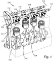
- Fig. 1 conceptually illustrates an exemplary combustion engine 100 for a vehicle.
- the combustion engine comprises multiple cylinders (not shown) and multiple pistons 104.
- each of the cylinder is a respective piston 104 arranged.
- the pistons 104 are forced to move in the respective cylinder by the ignition of fuel in the cylinder volume.
- the stroke motion of the piston in the cylinder is transferred to a crankshaft 108 for transferring propulsion power to the driveline (not shown) of the vehicle comprising the combustion engine 100.
- a valve 109 (only one of several valves is numbered) is configured to open an air inlet to the cylinder volume at timed intervals.
- the timing is provided by a linking mechanism 111 (a so-called "timing belt") which is configured to rotate a first camshaft 110 about a rotation axis 112 such that a cam 114 of the camshaft 110 causes the first valve 109 to open and close in a synchronized manner with respect to the rotation of the crankshaft and thereby with respect to the strokes of the piston 104.
- a second camshaft 118 is configured to open and close a second valve 120 (only one is numbered).
- the timing of the operation of the second valve 120 is also is provided by the linking mechanism 111.
- the linking mechanism is configured to rotate the second camshaft 118 about a rotation axis 115 such that a cam 116 of the second camshaft 118 causes the second valve 120 to open and close in a synchronized manner with respect to the rotation of the crankshaft 108 and thereby with respect to the strokes of the piston 104.
- the second valve 120 controls the outflow of exhaust from the cylinder volume in a synchronized manner with the rotation of the crankshaft 108 and thereby with respect to the strokes of the piston 104.
- the timing relationship between the opening and closing of the valves 109 and 120 will be described further below.
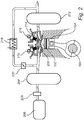
- Fig. 2 conceptually illustrates an air intake and exhaust outlet system of a combustion engine.
- fig. 2 schematically illustrates an intake surge tank 204 adapted to receive air from the outside environment via a compressor 206 and an air intake gas flow regulator 205 configured to regulate the gas flow into the intake surge tank 204 and to measure the gas flow into the intake surge tank 204.
- the compressor 206 provides pressurized air to the intake surge tank 204 via the air intake gas flow regulator 205.
- the compressor 206 may receive air from the outside environment through an intake port (not shown).
- pressure sensors are arranged to measure the pressure in the intake surge tank 204.
- the pressure sensor(s) may be a manifold pressure sensor (MAP sensor) located in the intake surge tank 204.
- MAP sensor manifold pressure sensor
- a temperature sensor is arranged to measure the temperature of the air in the intake surge tank 204. This may be advantageous for ensuring that too high temperature fluctuations in the intake occur.
- the intake surge tank 204 is in fluid communication with a cylinder volume 102 via an air intake control valve 208.
- a cam 210 of a camshaft is adapted to cause the spring loaded valve to open and close via the rotation of the camshaft as described with reference to Fig. 1 .
- an exhaust surge tank 212 is adapted to receive exhaust gas from the cylinder volume 102 via an exhaust outlet control valve 214.
- a cam 216 of a second camshaft is adapted to cause the spring loaded valve 216 to open and close via the rotation of the camshaft as described with reference to Fig. 1 .
- Some of the exhaust gas is circulated back via an exhaust gas recirculation cooler 218 and an exhaust gas recirculation valve 220 to be mixed with air from the intake surge tank 204 before entering the cylinder volume via the air intake control valve 208.
- the intake surge tank 204 and the exhaust surge tank 212 have a fluid connection between each other.
- the air intake and exhaust outlet system may comprise further components such as backpressure valves and pressure regulators on the exhaust side of the cylinder. Such components are known per se to the skilled person.
- the air flow into the intake surge tank 204 is provided at a constant gas flow, controlled by the intake gas flow regulator 205, while the combustion engine is operated at a predetermined operation speed (e.g. RPM), at a relatively constant operation temperature.
- a predetermined operation speed e.g. RPM
- camshafts comprising the respective cams 210 and 216 are rotated and camshaft position sensors measure their positions relative a reference position.
- the camshaft position is generally given by a rotation angle with respect to the reference position and may be measured by cam sensors (not shown), such cam sensors are known per se to the skilled person and may be implemented by means of inductive sensors sensing a magnet attached to the cam shaft, Hall effect sensors sensing a magnetic field from the magnet, or AC coupled sensor sensing a magnetic field affected by the rotating of the camshaft.
- the cams 210 and 216 cause a respective valve 208, 214 to open and close a respective opening to the cylinder volume 102.
- the opening and closing of each valve causes a pressure variation in the intake surge tank 204.
- the pressure values indicative of the pressure variation is measured simultaneously as the positions of the camshafts are measured.
- a camshaft signature is comprised of a set of camshaft positions and a set of pressure values, for at least one of the camshafts.
- a camshaft positioning system for camshaft positioning of a camshaft may thus comprise a control unit configured to control the combustion engine to operate at a predetermined rotation speed and operation temperature.
- the control unit may control an intake gas flow regulator 205 to provide a constant gas flow into the intake surge tank 204. Further the control unit measures a set of camshaft positions using the cam sensors and a set of pressure values indicative of the pressure in the intake surge tank using the pressure sensors while the camshaft is rotated and the gas flow into the intake surge tank 204 is maintained constant.
- the control unit may subsequently provide a camshaft signature comprising the set of camshaft positions and the set of pressure values.
- Fig. 3a schematically illustrates an exemplary rotational position of a cam 301.
- the cam 301 has rotated an angle ⁇ with respect to a reference position.
- the rotational angle ⁇ may represent a camshaft position.
- Several reference positions are possible and the reference position shown in fig. 3a is only shown for exemplary purposes.
- Fig. 3b show a cam diagram which describes the angular position of a cam controlling an air intake valve and the angular position of a cam controlling an exhaust valve.
- the anatomy of a camshaft comprises a cylindrical shaft comprising cams in the shape of lobes extending transversal to the shaft.
- the cams are configured to convert the rotary motion of the shaft to a translational motion for controlling the reciprocal motion of a valve.
- the anatomy of the cam results in position of the valve which can be described in a diagram as illustrated in fig. 3 .
- the lobe represented by curve 302 describes the valve position for an exhaust valve and the lobe represented by curve 304 describes the valve position for an intake valve, each caused by a respective camshaft rotation.
- the cam represented by lobe 302 is at a position such the exhaust vale lift exceeds the level 308 the exhaust valve is fully open to allow the release of exhaust gases from the cylinder volume.
- the cam represented by lobe 304 is at a position where the intake valve lift exceeds the level 308, then the intake valve is fully open to allow the intake of air into the cylinder volume.
- the overlap 310 between the lobes 302 and 304 provides for a short time duration where the air intake and exhaust outlet are at least partly open simultaneously.
- this is another addition to that the opening and closing of each valve causes a pressure variation in the intake surge tank 204.
- valve motion of the intake valve 210 and exhaust valves 216 is controlled directly or indirectly (via other linking mechanisms) via the anatomy of the cams of the camshafts
- the pressure conditions in the intake surge tank 204 will also be affected by the anatomy of the camshaft and the design of any other linking mechanism related to the control of the valves 210 and 216 via the camshaft.
- the camshafts and the valves, (and other linking mechanisms) are all subject to manufacturing and assembly tolerances which mean that each combustion engine is unique. For this reason, it is possible to generate camshaft signatures when the combustion engine is manufactured and the camshaft positions are initially configured.
- a set of pressure values and associated camshaft position values serve as a camshaft signature.
- a camshaft signature may be determined when the vehicle combustion engine is manufactured.
- the camshaft signature may be stored. At a later time, the camshaft signature may be retrieved and used for re-calibration of the camshafts.
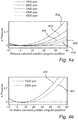
- Fig. 4a illustrates a set of camshaft signatures 402, 404, 406, 408, 410 for different rpms of the engine, 1000 rpm, 2000 rpm, 3000 rpm, 4000 rpm, 4500 rpm, respectively, of the combustion engine.
- the camshaft signatures on fig 4a are for illustratively purposes shown for a camshaft responsible for controlling an exhaust control valve (see valve 214 in fig. 2 ).
- the camshaft signatures comprises a set of camshaft positions for the camshaft and the set of pressure values (y-axis) indicative of the pressure difference in the surge intake tank for the respective camshaft position relative the pressure at zero angular position for the camshaft.
- the pressure values are provided as a pressure difference relative the pressure at the predetermined reference position of the camshaft, i.e. at zero degrees rotational position.
- Fig. 4b illustrates a further pair of camshaft signatures 420 and 422 for different rpms, 1500 rpm and 2500 rpm, respectively, of the combustion engine.
- the camshaft signatures on fig 4b are for illustratively purposes shown for a camshaft responsible for controlling an air intake control valve (see 208 in fig. 2 ).
- the camshaft signatures comprises a set of camshaft positions for the camshaft and the set of pressure values (y-axis) indicative of the pressure in the surge intake tank for the respective camshaft position relative the pressure at zero angular position for the camshaft.
- Fig. 5 illustrates a flow-chart of method steps according to example embodiments.
- a first step S102 the combustion engine is operated at a predetermined rotation speed.
- step S104 providing a constant gas flow into the intake surge tank.
- step S106 measuring a set of camshaft positions and a set of pressure values indicative of the pressure in the intake surge tank while the camshaft is rotated and the gas flow into the intake surge tank is maintained constant.
- a camshaft signature is provided in step S108 comprising the set of camshaft positions and the set of pressure values.
- FIG. 6 illustrates a flow-chart of method steps according to example embodiments.
- a camshaft signature indicative of a camshaft positioning calibration is retrieved in step S202.
- the combustion engine is operated at a predetermined rotation speed in step S204.
- a constant gas flow is provided into the intake surge tank in step S206.
- step S208 measuring a set of camshaft positions and a set of pressure values indicative of the pressure in the intake surge tank while the camshaft is rotated and the gas flow into the intake surge tank is maintained constant.
- the set of camshaft positions and the set of pressure values are compared with the camshaft signature in step S210.
- An instruction indicative of the outcome of the comparison is provided in step S212.
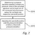
- Fig. 7 illustrates a flow-chart of method steps according to example embodiments.
- the camshaft position may be adjusted according to the instruction provided in step S212 in fig. 6 .
- the adjustment may be determined by firstly determining (S216) a pressure deviation between at least one pressure value of the camshaft signature and at least one of the measured set of pressure values for a at least one respective camshaft position.
- the camshaft position is adjusted in step S218 until the pressure deviation is below a threshold pressure deviation.
- the pressure deviation is minimized.
- the adjustment of the camshaft position is performed while the engine is running.
- control functionality of the present disclosure may be implemented using existing computer processors, or by a special purpose computer processor for an appropriate system, incorporated for this or another purpose, or by a hardwire system.
- Embodiments within the scope of the present disclosure include program products comprising machine-readable medium for carrying or having machine-executable instructions or data structures stored thereon.
- Such machine-readable media can be any available media that can be accessed by a general purpose or special purpose computer or other machine with a processor.
- machine-readable media can comprise RAM, ROM, EPROM, EEPROM, CD-ROM or other optical disk storage, magnetic disk storage or other magnetic storage devices, or any other medium which can be used to carry or store desired program code in the form of machine-executable instructions or data structures and which can be accessed by a general purpose or special purpose computer or other machine with a processor.
- a network or another communications connection either hardwired, wireless, or a combination of hardwired or wireless
- any such connection is properly termed a machine-readable medium.
- Machine-executable instructions include, for example, instructions and data which cause a general purpose computer, special purpose computer, or special purpose processing machines to perform a certain function or group of functions.
Landscapes
- Engineering & Computer Science (AREA)
- Mechanical Engineering (AREA)
- General Engineering & Computer Science (AREA)
- Physics & Mathematics (AREA)
- General Physics & Mathematics (AREA)
- Chemical & Material Sciences (AREA)
- Combustion & Propulsion (AREA)
- Combined Controls Of Internal Combustion Engines (AREA)
- Output Control And Ontrol Of Special Type Engine (AREA)
Abstract
Description
- The present invention relates to methods for camshaft positioning calibration and to a corresponding camshaft positioning system.
- Camshafts are common in combustion engines for controlling various valves in the combustion engines. A camshaft comprises of a shaft and at least one, often several, cams arranged on the shaft. As the shaft rotates, the cam moves around the rotation axis of the shaft and causes the valve to open or close depending on the rotational position of the camshaft.
- By careful design and accurate positioning of the camshaft it is possible to achieve high accuracy timing control of the valve. One valve is typically arranged to control the flow of an air/fuel mixture into the cylinder of the combustion engine, and another valve to control the release of exhaust gases from the cylinder. A crankshaft controls the stroke of a piston in the cylinder according to a combustion cycle of the engine. Consequently, it is of high importance that the timing relationship between the crankshaft and the camshafts is accurate. Poor timing of the camshaft results in a higher fuel consumption and an increase in exhaust gases released in the environment.
- Furthermore, although in the production of vehicles the timing of the camshafts is calibrated, it difficult to restore the originally calibrated camshaft positioning in an accurate way.
- Accordingly, there is a need for improved camshaft positioning calibration.
- In view of above, it is an object of the present invention to provide improved camshaft positioning calibration that allows for camshaft positioning calibration of individual camshafts.
- According to a first aspect of the invention, there is provided a method for generating a camshaft signature for camshaft positioning calibration for a camshaft comprised in an combustion engine, the camshaft is adapted to cause a valve to open and close an opening to a cylinder volume of the combustion engine, the combustion engine further comprises in intake surge tank adapted for receiving air from the outside environment, the intake surge tank is in fluid connection with the cylinder volume of the combustion engine for providing air for mixing with fuel injected into the cylinder, wherein the method comprises: operating the combustion engine at a predetermined rotation speed; providing a constant gas flow into the intake surge tank; measuring a set of camshaft positions and a set of pressure values indicative of the pressure in the intake surge tank while the camshaft is rotated and the gas flow into the intake surge tank is maintained constant; and providing a camshaft signature comprising the set of camshaft positions and the set of pressure values.
- The present invention is based on the realization that the camshaft position is related to the pressure in the intake surge tank. The camshaft position is directly related to the valve position, in other words, to what degree the valve is open.
- When the valves open or close the opening to the cylinder volume, the fluid connection between the intake surge tank and the cylinder volume is varied whereby also the measurable pressure in the intake surge tank varies. Consequently, it is possible to relate the position of the camshaft to the measureable pressure in the intake surge tank. In this way, the camshaft signature provides a "fingerprint" for an individual camshaft. Thus, the camshaft signature may be considered unique for that specific camshaft in its engine.
- The camshaft signature may be stored in a memory and used for subsequent positioning of the camshaft.
- The gas flow into the intake surge tank is maintained constant so that the measureable pressure variation in the intake surge tank is caused by the opening or closing of the valve by the rotation of the camshaft.
- The rotation of the camshaft is performed in a controlled manner (i.e. at a controlled speed) such that the positions of the camshaft may be measured.
- The positions of the camshaft refer to rotational positions of the camshaft with respect to a pre-defined reference position. The rotational positions may be provided as a relative rotation angle from the reference position.
- The pressure values may be provided as pressure difference values relative the pressure at the pre-defined reference position of the camshaft. The pre-defined position of the camshaft may be defined as zero degrees rotational angle.
- The predetermined rotation speed may be set by specifying an engine RPM (revolutions per minute). The rotation speed of the vehicle is maintained constant such that an operating temperature of the engine may be ensured to be relatively constant during the generation of a camshaft signature. Maintaining a constant operating temperature reduces the influence of temperature fluctuations on the measured pressure in the intake valve.
- In embodiments, the camshaft may be adapted to control one of an air intake control valve and an exhaust outlet control valve of the combustion engine.
- The camshaft signature may also comprise timing relationships between the set of camshaft positions and set of pressure values. In other words, the camshaft signature may comprise correlated time series of camshaft positions and pressure values in order to provide a more accurate camshaft signature.
- According to embodiments, the method may comprise operating the combustion engine at a further predetermined rotation speed; measuring a further set of camshaft positions and a further set of pressure values indicative of the pressure in the intake surge tank while the camshaft is rotated and the gas flow into the intake surge tank is maintained constant; and providing a camshaft signature comprising the sets of camshaft positions and the sets of pressure values for the further rotation speeds of the combustion engine.
- Accordingly, the camshaft signature may advantageously comprise camshaft positions and pressure values measured at more than one rotation speed of the engine. The camshaft signature may in such case be considered to comprise of a set of partial camshaft signatures a first partial camshaft signature at a first rotation speed and a second partial camshaft signature at a second rotation speed.
- According to embodiments, the combustion engine may comprise a first camshaft adapted to control an air intake control valve of the combustion engine and a second camshaft adapted to control an exhaust outlet control valve of the combustion engine, the method may comprise: measuring a set of camshaft positions for the first camshaft and a set of camshaft positions for the second camshaft while the camshafts are being rotated, and a set of pressure values indicative of the pressure in the intake surge tank while the camshafts are rotated and the gas flow into the intake surge tank is maintained constant; and providing a camshaft signature comprising the sets of camshaft positions and the set of pressure values. Thus, the camshaft signature may comprise camshaft positions and pressure values for more than one camshaft which thereby enables to provide a camshaft signature for positioning calibration of more than one camshaft.
- In the above case, the camshaft signature may comprise timing relationships between the each of the sets of camshaft positions and the set of pressure values, and between the sets of camshaft positions.
- According to a second aspect of the invention, there is provided a method for calibrating a camshaft position for a camshaft of a combustion engine, the camshaft is adapted to control a valve to open and close an opening to a cylinder volume of the combustion engine, the combustion engine further comprises in intake surge tank adapted for receiving air from the outside environment, the intake surge tank is in fluid connection with the cylinder volume of the combustion engine for providing air for mixing with fuel injected into the cylinder, wherein the method comprises: retrieving a camshaft signature indicative of a camshaft positioning calibration; operating the combustion engine at a predetermined rotation speed; providing a constant gas flow into the intake surge tank; measuring a set of camshaft positions and a set of pressure values indicative of the pressure in the intake surge tank while the camshaft is rotated and the gas flow into the intake surge tank is maintained constant; comparing the set of camshaft positions and the set of pressure values with the camshaft signature, and providing an instruction indicative of the outcome of the comparison.
- Accordingly, the present invention is further based on the realization to use the provided camshaft signature for enabling accurate adjustment of a camshaft. The adjustment may be performed subsequent to production of the vehicle, e.g. at a workshop by first retrieving the stored camshaft signature from a memory which may be comprised in the vehicle or stored on a server.
- The camshaft position may be adjusted according to the provided instruction.
- For instance, in some embodiments, adjustment may be provided by determining a pressure deviation between at least one pressure value of the camshaft signature and at least one of the measured set of pressure values for a at least one respective camshaft position, and adjusting the camshaft position until the pressure deviation is below a threshold pressure deviation. Thus a relatively straight forward but accurate camshaft position adjustment control is provided by the ability to relate the camshaft position to a pressure deviation. The camshaft position adjustment may be performed while the engine is operative.
- The camshaft position may adjusted so that the pressure deviation is minimized. In this way the camshaft position is ensured to be as close as possible to the position indicated by the camshaft signature.
- This second aspect of the invention provides similar advantages as discussed above in relation to the previous aspect of the invention.
- According to a third aspect of the invention, there is provided a camshaft positioning system for camshaft positioning of a camshaft comprised in an combustion engine, the camshaft is adapted to cause a valve to open and close an opening to a cylinder volume of the combustion engine, the combustion engine further comprises in intake surge tank adapted for receiving air from the outside environment, the intake surge tank is in fluid connection with the cylinder volume of the combustion engine for providing air for mixing with fuel injected into the cylinder, the system comprises a control unit configured to: control the combustion engine to operate at a predetermined rotation speed; control an inflow valve to provide a constant gas flow into the intake surge tank; measure a set of camshaft positions and a set of pressure values indicative of the pressure in the intake surge tank while the camshaft is rotated and the gas flow into the intake surge tank is maintained constant; and provide a camshaft signature comprising the set of camshaft positions and the set of pressure values.
- In embodiments, the control unit may be configured to perform a camshaft calibration procedure comprising to: retrieve a camshaft signature indicative of a camshaft positioning calibration; operate the combustion engine at a predetermined rotation speed and operation temperature; provide a constant gas flow into the intake surge tank; measure a set of camshaft positions and a set of pressure values indicative of the pressure in the intake surge tank while the camshaft is rotated and the gas flow into the intake surge tank is maintained constant; compare the set of camshaft positions and the set of pressure values with the camshaft signature, and provide an instruction indicative of the outcome of the comparison.
- The system may comprise a memory for storing the camshaft signature.
- The combustion engine may be configured to provide propulsion for a vehicle.
- Further features of, and advantages with, the present invention will become apparent when studying the appended claims and the following description. The skilled person realize that different features of the present invention may be combined to create embodiments other than those described in the following, without departing from the scope of the present invention.
- These and other aspects of the present invention will now be described in more detail, with reference to the appended drawings showing example embodiments of the invention, wherein:
-
Fig. 1 conceptually illustrates a combustion engine with a crankshaft and camshafts; -
Fig. 2 schematically illustrates embodiments of the invention; -
Fig. 3a schematically illustrates a rotational position of a cam; -
Fig. 3b schematically illustrates a timing diagram of an air intake cam and an exhaust cam; -
Fig. 4a conceptually illustrates camshaft signatures; -
Fig. 4b conceptually illustrates camshaft signatures; -
Fig. 5 is a flow chart of method steps according to embodiments of the invention; -
Fig. 6 is a flow chart of method steps according to embodiments of the invention; and -
Fig. 7 is a flow chart of additional method steps according to embodiments of the invention. - In the present detailed description, various embodiments of the system and method according to the present invention are described. However, this invention may generally be embodied in many different forms and should not be construed as limited to the embodiments set forth herein; rather, these embodiments are provided for thoroughness and completeness, and fully convey the scope of the invention to the skilled person. Like reference characters refer to like elements throughout.
-
Fig. 1 conceptually illustrates anexemplary combustion engine 100 for a vehicle. The combustion engine comprises multiple cylinders (not shown) andmultiple pistons 104. In each of the cylinder is arespective piston 104 arranged. Thepistons 104 are forced to move in the respective cylinder by the ignition of fuel in the cylinder volume. The stroke motion of the piston in the cylinder is transferred to acrankshaft 108 for transferring propulsion power to the driveline (not shown) of the vehicle comprising thecombustion engine 100. - Further, in order to allow air to mix with the fuel in the cylinder volume a valve 109 (only one of several valves is numbered) is configured to open an air inlet to the cylinder volume at timed intervals. The timing is provided by a linking mechanism 111 (a so-called "timing belt") which is configured to rotate a
first camshaft 110 about arotation axis 112 such that acam 114 of thecamshaft 110 causes thefirst valve 109 to open and close in a synchronized manner with respect to the rotation of the crankshaft and thereby with respect to the strokes of thepiston 104. - Furthermore, a
second camshaft 118 is configured to open and close a second valve 120 (only one is numbered). The timing of the operation of thesecond valve 120 is also is provided by thelinking mechanism 111. Thus, the linking mechanism is configured to rotate thesecond camshaft 118 about arotation axis 115 such that acam 116 of thesecond camshaft 118 causes thesecond valve 120 to open and close in a synchronized manner with respect to the rotation of thecrankshaft 108 and thereby with respect to the strokes of thepiston 104. - The
second valve 120 controls the outflow of exhaust from the cylinder volume in a synchronized manner with the rotation of thecrankshaft 108 and thereby with respect to the strokes of thepiston 104. The timing relationship between the opening and closing of thevalves -
Fig. 2 conceptually illustrates an air intake and exhaust outlet system of a combustion engine. In detailfig. 2 schematically illustrates anintake surge tank 204 adapted to receive air from the outside environment via acompressor 206 and an air intakegas flow regulator 205 configured to regulate the gas flow into theintake surge tank 204 and to measure the gas flow into theintake surge tank 204. Thecompressor 206 provides pressurized air to theintake surge tank 204 via the air intakegas flow regulator 205. Thecompressor 206 may receive air from the outside environment through an intake port (not shown). - Further, pressure sensors (not shown) are arranged to measure the pressure in the
intake surge tank 204. The pressure sensor(s) may be a manifold pressure sensor (MAP sensor) located in theintake surge tank 204. Further, is some possible implementations a temperature sensor is arranged to measure the temperature of the air in theintake surge tank 204. This may be advantageous for ensuring that too high temperature fluctuations in the intake occur. - The
intake surge tank 204 is in fluid communication with acylinder volume 102 via an airintake control valve 208. Acam 210 of a camshaft is adapted to cause the spring loaded valve to open and close via the rotation of the camshaft as described with reference toFig. 1 . - Furthermore, an
exhaust surge tank 212 is adapted to receive exhaust gas from thecylinder volume 102 via an exhaustoutlet control valve 214. Acam 216 of a second camshaft is adapted to cause the spring loadedvalve 216 to open and close via the rotation of the camshaft as described with reference toFig. 1 . - Some of the exhaust gas is circulated back via an exhaust
gas recirculation cooler 218 and an exhaustgas recirculation valve 220 to be mixed with air from theintake surge tank 204 before entering the cylinder volume via the airintake control valve 208. Thus, theintake surge tank 204 and theexhaust surge tank 212 have a fluid connection between each other. - The air intake and exhaust outlet system may comprise further components such as backpressure valves and pressure regulators on the exhaust side of the cylinder. Such components are known per se to the skilled person.
- In embodiments of the invention, the air flow into the
intake surge tank 204 is provided at a constant gas flow, controlled by the intakegas flow regulator 205, while the combustion engine is operated at a predetermined operation speed (e.g. RPM), at a relatively constant operation temperature. - The camshafts comprising the
respective cams - As the camshafts are rotated, the
cams respective valve cylinder volume 102. The opening and closing of each valve causes a pressure variation in theintake surge tank 204. The pressure values indicative of the pressure variation is measured simultaneously as the positions of the camshafts are measured. - A camshaft signature is comprised of a set of camshaft positions and a set of pressure values, for at least one of the camshafts.
- A camshaft positioning system for camshaft positioning of a camshaft may thus comprise a control unit configured to control the combustion engine to operate at a predetermined rotation speed and operation temperature. The control unit may control an intake
gas flow regulator 205 to provide a constant gas flow into theintake surge tank 204. Further the control unit measures a set of camshaft positions using the cam sensors and a set of pressure values indicative of the pressure in the intake surge tank using the pressure sensors while the camshaft is rotated and the gas flow into theintake surge tank 204 is maintained constant. The control unit may subsequently provide a camshaft signature comprising the set of camshaft positions and the set of pressure values. -
Fig. 3a schematically illustrates an exemplary rotational position of acam 301. Thecam 301 has rotated an angle α with respect to a reference position. The rotational angle α may represent a camshaft position. Several reference positions are possible and the reference position shown infig. 3a is only shown for exemplary purposes. -
Fig. 3b show a cam diagram which describes the angular position of a cam controlling an air intake valve and the angular position of a cam controlling an exhaust valve. Generally, the anatomy of a camshaft comprises a cylindrical shaft comprising cams in the shape of lobes extending transversal to the shaft. The cams are configured to convert the rotary motion of the shaft to a translational motion for controlling the reciprocal motion of a valve. The anatomy of the cam results in position of the valve which can be described in a diagram as illustrated infig. 3 . - The lobe represented by
curve 302 describes the valve position for an exhaust valve and the lobe represented bycurve 304 describes the valve position for an intake valve, each caused by a respective camshaft rotation. When the cam represented bylobe 302 is at a position such the exhaust vale lift exceeds thelevel 308 the exhaust valve is fully open to allow the release of exhaust gases from the cylinder volume. Similarly, when the cam represented bylobe 304 is at a position where the intake valve lift exceeds thelevel 308, then the intake valve is fully open to allow the intake of air into the cylinder volume. - Moreover, the
overlap 310 between thelobes intake surge tank 204. - Accordingly, since the valve motion of the
intake valve 210 andexhaust valves 216 is controlled directly or indirectly (via other linking mechanisms) via the anatomy of the cams of the camshafts, the pressure conditions in theintake surge tank 204 will also be affected by the anatomy of the camshaft and the design of any other linking mechanism related to the control of thevalves - Accordingly, a set of pressure values and associated camshaft position values serve as a camshaft signature. Such a camshaft signature may be determined when the vehicle combustion engine is manufactured. The camshaft signature may be stored. At a later time, the camshaft signature may be retrieved and used for re-calibration of the camshafts.
-
Fig. 4a illustrates a set ofcamshaft signatures fig 4a are for illustratively purposes shown for a camshaft responsible for controlling an exhaust control valve (seevalve 214 infig. 2 ). The camshaft signatures comprises a set of camshaft positions for the camshaft and the set of pressure values (y-axis) indicative of the pressure difference in the surge intake tank for the respective camshaft position relative the pressure at zero angular position for the camshaft. In other words, the pressure values are provided as a pressure difference relative the pressure at the predetermined reference position of the camshaft, i.e. at zero degrees rotational position. -
Fig. 4b illustrates a further pair ofcamshaft signatures fig 4b are for illustratively purposes shown for a camshaft responsible for controlling an air intake control valve (see 208 infig. 2 ). The camshaft signatures comprises a set of camshaft positions for the camshaft and the set of pressure values (y-axis) indicative of the pressure in the surge intake tank for the respective camshaft position relative the pressure at zero angular position for the camshaft. -
Fig. 5 illustrates a flow-chart of method steps according to example embodiments. In a first step S102 the combustion engine is operated at a predetermined rotation speed. Subsequently, in step S104 providing a constant gas flow into the intake surge tank. In step S106, measuring a set of camshaft positions and a set of pressure values indicative of the pressure in the intake surge tank while the camshaft is rotated and the gas flow into the intake surge tank is maintained constant. A camshaft signature is provided in step S108 comprising the set of camshaft positions and the set of pressure values. -
Fig. 6 illustrates a flow-chart of method steps according to example embodiments. A camshaft signature indicative of a camshaft positioning calibration is retrieved in step S202. Next, the combustion engine is operated at a predetermined rotation speed in step S204. A constant gas flow is provided into the intake surge tank in step S206. In step S208, measuring a set of camshaft positions and a set of pressure values indicative of the pressure in the intake surge tank while the camshaft is rotated and the gas flow into the intake surge tank is maintained constant. The set of camshaft positions and the set of pressure values are compared with the camshaft signature in step S210. An instruction indicative of the outcome of the comparison is provided in step S212. -
Fig. 7 illustrates a flow-chart of method steps according to example embodiments. The camshaft position may be adjusted according to the instruction provided in step S212 infig. 6 . The adjustment may be determined by firstly determining (S216) a pressure deviation between at least one pressure value of the camshaft signature and at least one of the measured set of pressure values for a at least one respective camshaft position. The camshaft position is adjusted in step S218 until the pressure deviation is below a threshold pressure deviation. Preferably, the pressure deviation is minimized. - The adjustment of the camshaft position is performed while the engine is running.
- The control functionality of the present disclosure may be implemented using existing computer processors, or by a special purpose computer processor for an appropriate system, incorporated for this or another purpose, or by a hardwire system. Embodiments within the scope of the present disclosure include program products comprising machine-readable medium for carrying or having machine-executable instructions or data structures stored thereon. Such machine-readable media can be any available media that can be accessed by a general purpose or special purpose computer or other machine with a processor. By way of example, such machine-readable media can comprise RAM, ROM, EPROM, EEPROM, CD-ROM or other optical disk storage, magnetic disk storage or other magnetic storage devices, or any other medium which can be used to carry or store desired program code in the form of machine-executable instructions or data structures and which can be accessed by a general purpose or special purpose computer or other machine with a processor. When information is transferred or provided over a network or another communications connection (either hardwired, wireless, or a combination of hardwired or wireless) to a machine, the machine properly views the connection as a machine-readable medium. Thus, any such connection is properly termed a machine-readable medium. Combinations of the above are also included within the scope of machine-readable media. Machine-executable instructions include, for example, instructions and data which cause a general purpose computer, special purpose computer, or special purpose processing machines to perform a certain function or group of functions.
- Although the figures may show a sequence the order of the steps may differ from what is depicted. Also two or more steps may be performed concurrently or with partial concurrence. Such variation will depend on the software and hardware systems chosen and on designer choice. All such variations are within the scope of the disclosure. Likewise, software implementations could be accomplished with standard programming techniques with rule based logic and other logic to accomplish the various connection steps, processing steps, comparison steps and decision steps.
- The person skilled in the art realizes that the present invention by no means is limited to the preferred embodiments described above. On the contrary, many modifications and variations are possible within the scope of the appended claims.
- In the claims, the word "comprising" does not exclude other elements or steps, and the indefinite article "a" or "an" does not exclude a plurality. A single processor or other unit may fulfill the functions of several items recited in the claims. The mere fact that certain measures are recited in mutually different dependent claims does not indicate that a combination of these measured cannot be used to advantage. Any reference signs in the claims should not be construed as limiting the scope.
Claims (15)
- A method for generating a camshaft signature for camshaft positioning calibration for a camshaft (102, 104) comprised in an combustion engine (100), the camshaft is adapted to cause a valve (109,120) to open and close an opening to a cylinder volume (102) of the combustion engine, the combustion engine further comprises in intake surge tank (204) adapted for receiving air from the outside environment, the intake surge tank is in fluid connection with the cylinder volume of the combustion engine for providing air for mixing with fuel injected into the cylinder, wherein the method comprises:- operating (S102) the combustion engine at a predetermined rotation speed;- providing (S104) a constant gas flow into the intake surge tank;- measuring (S106) a set of camshaft positions and a set of pressure values indicative of the pressure in the intake surge tank while the camshaft is rotated and the gas flow into the intake surge tank is maintained constant; and- providing (S108) a camshaft signature comprising the set of camshaft positions and the set of pressure values.
- The method according to claim 1, wherein the camshaft is adapted to control one of an air intake control valve (208) and an exhaust outlet control valve (214) of the combustion engine.
- The method according to any one of claim 1 or 2, wherein the camshaft signature comprises timing relationships between the set of camshaft positions and set of pressure values.
- The method according to any one of the preceding claims, comprising:- operating the combustion engine at a further predetermined rotation speed;- measuring a further set of camshaft positions and a further set of pressure values indicative of the pressure in the intake surge tank while the camshaft is rotated and the gas flow into the intake surge tank is maintained constant; and- providing a camshaft signature comprising the sets of camshaft positions and the sets of pressure values for the further rotation speeds of the combustion engine.
- The method according to any one of the preceding claims, wherein the combustion engine comprises a first camshaft adapted to control an air intake control valve of the combustion engine and a second camshaft adapted to control an exhaust outlet control valve of the combustion engine, the method comprising:- measuring a set of camshaft positions for the first camshaft and a set of camshaft positions for the second camshaft while the camshafts are being rotated, and a set of pressure values indicative of the pressure in the intake surge tank while the camshafts are rotated and the gas flow into the intake surge tank is maintained constant; and- providing a camshaft signature comprising the sets of camshaft positions and the set of pressure values.
- The method according to any one of the preceding claims, wherein the camshaft signature comprises timing relationships between the each of the sets of camshaft positions and the set of pressure values, and between the sets of camshaft positions.
- The method according to any one of the preceding claims, comprising storing the camshaft signature in a memory.
- A method for calibrating a camshaft position for a camshaft of a combustion engine, the camshaft is adapted to control a valve to open and close an opening to a cylinder volume of the combustion engine, the combustion engine further comprises in intake surge tank adapted for receiving air from the outside environment, the intake surge tank is in fluid connection with the cylinder volume of the combustion engine for providing air for mixing with fuel injected into the cylinder, wherein the method comprises:- retrieving (S202) a camshaft signature indicative of a camshaft positioning calibration;- operating (S204) the combustion engine at a predetermined rotation speed;- providing (S206) a constant gas flow into the intake surge tank;- measuring (S208) a set of camshaft positions and a set of pressure values indicative of the pressure in the intake surge tank while the camshaft is rotated and the gas flow into the intake surge tank is maintained constant;- comparing (S210) the set of camshaft positions and the set of pressure values with the camshaft signature, and- providing (S212) an instruction indicative of the outcome of the comparison.
- The method according to claim 8, comprising:- adjusting a camshaft position according to the instruction.
- The method according to claim 8 or 9, comprising:- determining (S216) a pressure deviation between at least one pressure value of the camshaft signature and at least one of the measured set of pressure values for a at least one respective camshaft position, and- adjusting (S218) the camshaft position until the pressure deviation is below a threshold pressure deviation.
- The method according to claim 10, wherein the camshaft position is adjusted so that the pressure deviation is minimized.
- A camshaft positioning system for camshaft positioning of a camshaft comprised in an combustion engine, the camshaft (110;118) is adapted to cause a valve (208;214) to open and close an opening to a cylinder volume of the combustion engine, the combustion engine further comprises in intake surge tank adapted for receiving air from the outside environment, the intake surge tank is in fluid connection with the cylinder volume (102) of the combustion engine for providing air for mixing with fuel injected into the cylinder, the system comprises a control unit configured to:- control the combustion engine (100) to operate at a predetermined rotation speed;- control an intake gas flow regulator (205) to provide a constant gas flow into the intake surge tank;- measure a set of camshaft positions and a set of pressure values indicative of the pressure in the intake surge tank while the camshaft is rotated and the gas flow into the intake surge tank is maintained constant; and- provide a camshaft signature (402;404;406;408;410;420;422) comprising the set of camshaft positions and the set of pressure values.
- The camshaft positioning system according to claim 12, wherein the control unit is configured to perform a camshaft calibration procedure comprising to:- retrieve a camshaft signature indicative of a camshaft positioning calibration;- control the combustion engine to operate at a predetermined rotation speed;- control an intake gas flow regulator (205) to provide a constant gas flow into the intake surge tank;- measure a set of camshaft positions and a set of pressure values indicative of the pressure in the intake surge tank while the camshaft is rotated and the gas flow into the intake surge tank is maintained constant;- compare the set of camshaft positions and the set of pressure values with the camshaft signature, and- provide an instruction indicative of the outcome of the comparison.
- The system according to any one of claims, comprising a memory for storing the camshaft signature.
- The camshaft positioning system according to any one of claims 11 to 14, wherein the combustion engine is configured to provide propulsion for a vehicle.
Priority Applications (3)
| Application Number | Priority Date | Filing Date | Title |
|---|---|---|---|
| EP18175735.2A EP3578768B1 (en) | 2018-06-04 | 2018-06-04 | A method and system for camshaft positioning calibration |
| US16/408,530 US10876434B2 (en) | 2018-06-04 | 2019-05-10 | Method and system for camshaft positioning calibration |
| CN201910450794.4A CN110553608B (en) | 2018-06-04 | 2019-05-28 | Method and system for camshaft positioning calibration |
Applications Claiming Priority (1)
| Application Number | Priority Date | Filing Date | Title |
|---|---|---|---|
| EP18175735.2A EP3578768B1 (en) | 2018-06-04 | 2018-06-04 | A method and system for camshaft positioning calibration |
Publications (2)
| Publication Number | Publication Date |
|---|---|
| EP3578768A1 true EP3578768A1 (en) | 2019-12-11 |
| EP3578768B1 EP3578768B1 (en) | 2023-01-11 |
Family
ID=62528322
Family Applications (1)
| Application Number | Title | Priority Date | Filing Date |
|---|---|---|---|
| EP18175735.2A Active EP3578768B1 (en) | 2018-06-04 | 2018-06-04 | A method and system for camshaft positioning calibration |
Country Status (3)
| Country | Link |
|---|---|
| US (1) | US10876434B2 (en) |
| EP (1) | EP3578768B1 (en) |
| CN (1) | CN110553608B (en) |
Families Citing this family (3)
| Publication number | Priority date | Publication date | Assignee | Title |
|---|---|---|---|---|
| DE102020207175B3 (en) * | 2020-06-09 | 2021-07-01 | Volkswagen Aktiengesellschaft | Method for determining a camshaft position of an internal combustion engine |
| DE102020207174B3 (en) * | 2020-06-09 | 2021-07-01 | Volkswagen Aktiengesellschaft | Method for determining a camshaft position of an internal combustion engine |
| DE102020207172B3 (en) * | 2020-06-09 | 2021-07-01 | Volkswagen Aktiengesellschaft | Method for determining a camshaft position of an internal combustion engine |
Citations (5)
| Publication number | Priority date | Publication date | Assignee | Title |
|---|---|---|---|---|
| US20090049897A1 (en) * | 2007-08-24 | 2009-02-26 | Olin Peter M | Method for on-line adaptation of engine volumetric efficiency using a mass air flow sensor |
| US20120116646A1 (en) * | 2010-11-04 | 2012-05-10 | Kia Motors Corporation | Method for compensating for valve lift deviation between engines equipped with cvvl mechanism |
| US20150040878A1 (en) * | 2013-08-09 | 2015-02-12 | Aisan Kogyo Kabushiki Kaisha | Failure detection device for blow-by gas recirculation apparatus of engine |
| US20170248093A1 (en) * | 2016-02-26 | 2017-08-31 | GM Global Technology Operations LLC | Method of continuously calculating trapped and scavenged air per cylinder |
| DE102016219584A1 (en) * | 2016-10-10 | 2018-04-12 | Continental Automotive Gmbh | Method for the combined identification of phase differences of the intake valve lift and the exhaust valve lift of an internal combustion engine by means of lines of identical phase positions and amplitudes |
Family Cites Families (15)
| Publication number | Priority date | Publication date | Assignee | Title |
|---|---|---|---|---|
| JPH04120411A (en) * | 1990-09-11 | 1992-04-21 | Musashi Seimitsu Ind Co Ltd | Detecting apparatus for groove of component such as cam shaft |
| JPH081376B2 (en) * | 1991-10-28 | 1996-01-10 | エイ イー ビショップ アンド アソシエイツ プロプライエタリー リミテッド | Equipment used to manufacture valves for hydraulic power steering systems |
| JP3232925B2 (en) * | 1994-03-10 | 2001-11-26 | トヨタ自動車株式会社 | Intake air amount calculation device for internal combustion engine |
| JP3309658B2 (en) * | 1995-08-25 | 2002-07-29 | トヨタ自動車株式会社 | Abnormality detection device for valve timing control device of internal combustion engine |
| US6463912B1 (en) * | 1998-04-22 | 2002-10-15 | Toyota Jidosha Kabushiki Kaisha | Intake air volume detection device for internal combustion engine |
| US6708566B1 (en) * | 2003-02-21 | 2004-03-23 | Robert Bosch Gmbh | Air gauge for measuring the geometry of precision machined fluid passages |
| US8150605B2 (en) * | 2009-02-17 | 2012-04-03 | Ford Global Technologies, Llc | Coordination of variable cam timing and variable displacement engine systems |
| CN102913334B (en) * | 2012-10-31 | 2015-06-10 | 浙江吉利汽车研究院有限公司杭州分公司 | Method for detecting air intake flow of engine cylinder |
| JP6011477B2 (en) * | 2013-06-28 | 2016-10-19 | 三菱自動車工業株式会社 | Engine control device |
| CN203584569U (en) * | 2013-10-25 | 2014-05-07 | 张毅 | System adopting fuel gas cold energy to improve heat efficiency of engine to realize energy conservation and emission reduction |
| US9297346B2 (en) * | 2014-03-17 | 2016-03-29 | Ford Global Technologies, Llc | Camshaft position determination |
| JP6350304B2 (en) * | 2015-01-26 | 2018-07-04 | トヨタ自動車株式会社 | Lean burn engine |
| EP3095984B1 (en) * | 2015-05-20 | 2018-01-03 | Volvo Car Corporation | An internal combustion engine and a method for controlling such an internal combustion engine |
| CN104875419B (en) * | 2015-06-10 | 2019-02-26 | 宁波钜智自动化装备有限公司 | A kind of structure and method of quick disassembly and assembly of mold |
| US10472999B2 (en) * | 2016-08-18 | 2019-11-12 | Ford Global Technologies, Llc | Methods and system for adjusting camshafts |
-
2018
- 2018-06-04 EP EP18175735.2A patent/EP3578768B1/en active Active
-
2019
- 2019-05-10 US US16/408,530 patent/US10876434B2/en active Active
- 2019-05-28 CN CN201910450794.4A patent/CN110553608B/en active Active
Patent Citations (5)
| Publication number | Priority date | Publication date | Assignee | Title |
|---|---|---|---|---|
| US20090049897A1 (en) * | 2007-08-24 | 2009-02-26 | Olin Peter M | Method for on-line adaptation of engine volumetric efficiency using a mass air flow sensor |
| US20120116646A1 (en) * | 2010-11-04 | 2012-05-10 | Kia Motors Corporation | Method for compensating for valve lift deviation between engines equipped with cvvl mechanism |
| US20150040878A1 (en) * | 2013-08-09 | 2015-02-12 | Aisan Kogyo Kabushiki Kaisha | Failure detection device for blow-by gas recirculation apparatus of engine |
| US20170248093A1 (en) * | 2016-02-26 | 2017-08-31 | GM Global Technology Operations LLC | Method of continuously calculating trapped and scavenged air per cylinder |
| DE102016219584A1 (en) * | 2016-10-10 | 2018-04-12 | Continental Automotive Gmbh | Method for the combined identification of phase differences of the intake valve lift and the exhaust valve lift of an internal combustion engine by means of lines of identical phase positions and amplitudes |
Also Published As
| Publication number | Publication date |
|---|---|
| CN110553608B (en) | 2022-03-15 |
| US10876434B2 (en) | 2020-12-29 |
| CN110553608A (en) | 2019-12-10 |
| EP3578768B1 (en) | 2023-01-11 |
| US20190368384A1 (en) | 2019-12-05 |
Similar Documents
| Publication | Publication Date | Title |
|---|---|---|
| US10287995B2 (en) | System and method for controlling a variable valve actuation system to reduce delay associated with reactivating a cylinder | |
| US9222427B2 (en) | Intake port pressure prediction for cylinder activation and deactivation control systems | |
| US9416743B2 (en) | Cylinder activation/deactivation sequence control systems and methods | |
| CN108350824B (en) | Method for combined identification of stroke phase difference of piston, inlet valve and outlet valve of internal combustion engine | |
| US9494092B2 (en) | System and method for predicting parameters associated with airflow through an engine | |
| US9534550B2 (en) | Air per cylinder determination systems and methods | |
| US10876434B2 (en) | Method and system for camshaft positioning calibration | |
| CN109790789B (en) | Method for detecting a phase difference between an inlet valve stroke and an outlet valve stroke of an internal combustion engine | |
| CN103195596B (en) | Spark ignition is to the transition control of homogeneous charge compression-ignition and method | |
| US20140069377A1 (en) | Volumetric efficiency determination systems and methods | |
| US20070288134A1 (en) | System and method for demonstrating functionality of on-board diagnostics for vehicles | |
| CN103670763A (en) | Engine control systems and methods for vehicle launch | |
| CN112395733B (en) | Method, controller, internal combustion engine and vehicle for modifying detected camshaft position | |
| CN107304723B (en) | System and method for adjusting lift state of valve actuator | |
| US9309803B2 (en) | Turbocharger compressor temperature control systems and methods | |
| CN104514640A (en) | System and method for estimating a turbine outlet temperature or a turbine inlet temperature based on a wastegate command | |
| US7779802B2 (en) | Simulated cam position for a V-type engine | |
| US10704504B1 (en) | Deceleration cylinder cut-off (DCCO) methodology with enhanced EGR | |
| US20060169231A1 (en) | Intake air amount control apparatus and intake air amount control method for internal combustion engine | |
| CN113107715B (en) | Dedicated exhaust gas recirculation control system and method | |
| US7467611B2 (en) | Rate limiting and balancing control system for dual independent camshaft phasing | |
| US9366196B2 (en) | System and method for limiting throttle opening area based on cam phaser position to minimize noise during acceleration | |
| CN106968742B (en) | Control device for internal combustion engine and method of controlling internal combustion engine | |
| CN106246381A (en) | Determine the system and method for the speed of electromotor when one or more cylinder deactivation in electromotor | |
| US9217386B2 (en) | System and method for preventing stochastic pre-ignition |
Legal Events
| Date | Code | Title | Description |
|---|---|---|---|
| PUAI | Public reference made under article 153(3) epc to a published international application that has entered the european phase |
Free format text: ORIGINAL CODE: 0009012 |
|
| STAA | Information on the status of an ep patent application or granted ep patent |
Free format text: STATUS: THE APPLICATION HAS BEEN PUBLISHED |
|
| AK | Designated contracting states |
Kind code of ref document: A1 Designated state(s): AL AT BE BG CH CY CZ DE DK EE ES FI FR GB GR HR HU IE IS IT LI LT LU LV MC MK MT NL NO PL PT RO RS SE SI SK SM TR |
|
| AX | Request for extension of the european patent |
Extension state: BA ME |
|
| STAA | Information on the status of an ep patent application or granted ep patent |
Free format text: STATUS: REQUEST FOR EXAMINATION WAS MADE |
|
| 17P | Request for examination filed |
Effective date: 20200706 |
|
| RBV | Designated contracting states (corrected) |
Designated state(s): AL AT BE BG CH CY CZ DE DK EE ES FI FR GB GR HR HU IE IS IT LI LT LU LV MC MK MT NL NO PL PT RO RS SE SI SK SM TR |
|
| GRAP | Despatch of communication of intention to grant a patent |
Free format text: ORIGINAL CODE: EPIDOSNIGR1 |
|
| STAA | Information on the status of an ep patent application or granted ep patent |
Free format text: STATUS: GRANT OF PATENT IS INTENDED |
|
| INTG | Intention to grant announced |
Effective date: 20220902 |
|
| GRAS | Grant fee paid |
Free format text: ORIGINAL CODE: EPIDOSNIGR3 |
|
| GRAA | (expected) grant |
Free format text: ORIGINAL CODE: 0009210 |
|
| STAA | Information on the status of an ep patent application or granted ep patent |
Free format text: STATUS: THE PATENT HAS BEEN GRANTED |
|
| AK | Designated contracting states |
Kind code of ref document: B1 Designated state(s): AL AT BE BG CH CY CZ DE DK EE ES FI FR GB GR HR HU IE IS IT LI LT LU LV MC MK MT NL NO PL PT RO RS SE SI SK SM TR |
|
| REG | Reference to a national code |
Ref country code: GB Ref legal event code: FG4D |
|
| REG | Reference to a national code |
Ref country code: CH Ref legal event code: EP |
|
| REG | Reference to a national code |
Ref country code: DE Ref legal event code: R096 Ref document number: 602018045236 Country of ref document: DE |
|
| REG | Reference to a national code |
Ref country code: IE Ref legal event code: FG4D |
|
| REG | Reference to a national code |
Ref country code: AT Ref legal event code: REF Ref document number: 1543546 Country of ref document: AT Kind code of ref document: T Effective date: 20230215 |
|
| REG | Reference to a national code |
Ref country code: LT Ref legal event code: MG9D |
|
| REG | Reference to a national code |
Ref country code: NL Ref legal event code: MP Effective date: 20230111 |
|
| REG | Reference to a national code |
Ref country code: AT Ref legal event code: MK05 Ref document number: 1543546 Country of ref document: AT Kind code of ref document: T Effective date: 20230111 |
|
| PG25 | Lapsed in a contracting state [announced via postgrant information from national office to epo] |
Ref country code: NL Free format text: LAPSE BECAUSE OF FAILURE TO SUBMIT A TRANSLATION OF THE DESCRIPTION OR TO PAY THE FEE WITHIN THE PRESCRIBED TIME-LIMIT Effective date: 20230111 |
|
| PG25 | Lapsed in a contracting state [announced via postgrant information from national office to epo] |
Ref country code: RS Free format text: LAPSE BECAUSE OF FAILURE TO SUBMIT A TRANSLATION OF THE DESCRIPTION OR TO PAY THE FEE WITHIN THE PRESCRIBED TIME-LIMIT Effective date: 20230111 Ref country code: PT Free format text: LAPSE BECAUSE OF FAILURE TO SUBMIT A TRANSLATION OF THE DESCRIPTION OR TO PAY THE FEE WITHIN THE PRESCRIBED TIME-LIMIT Effective date: 20230511 Ref country code: NO Free format text: LAPSE BECAUSE OF FAILURE TO SUBMIT A TRANSLATION OF THE DESCRIPTION OR TO PAY THE FEE WITHIN THE PRESCRIBED TIME-LIMIT Effective date: 20230411 Ref country code: LV Free format text: LAPSE BECAUSE OF FAILURE TO SUBMIT A TRANSLATION OF THE DESCRIPTION OR TO PAY THE FEE WITHIN THE PRESCRIBED TIME-LIMIT Effective date: 20230111 Ref country code: LT Free format text: LAPSE BECAUSE OF FAILURE TO SUBMIT A TRANSLATION OF THE DESCRIPTION OR TO PAY THE FEE WITHIN THE PRESCRIBED TIME-LIMIT Effective date: 20230111 Ref country code: HR Free format text: LAPSE BECAUSE OF FAILURE TO SUBMIT A TRANSLATION OF THE DESCRIPTION OR TO PAY THE FEE WITHIN THE PRESCRIBED TIME-LIMIT Effective date: 20230111 Ref country code: ES Free format text: LAPSE BECAUSE OF FAILURE TO SUBMIT A TRANSLATION OF THE DESCRIPTION OR TO PAY THE FEE WITHIN THE PRESCRIBED TIME-LIMIT Effective date: 20230111 Ref country code: AT Free format text: LAPSE BECAUSE OF FAILURE TO SUBMIT A TRANSLATION OF THE DESCRIPTION OR TO PAY THE FEE WITHIN THE PRESCRIBED TIME-LIMIT Effective date: 20230111 |
|
| PG25 | Lapsed in a contracting state [announced via postgrant information from national office to epo] |
Ref country code: SE Free format text: LAPSE BECAUSE OF FAILURE TO SUBMIT A TRANSLATION OF THE DESCRIPTION OR TO PAY THE FEE WITHIN THE PRESCRIBED TIME-LIMIT Effective date: 20230111 Ref country code: PL Free format text: LAPSE BECAUSE OF FAILURE TO SUBMIT A TRANSLATION OF THE DESCRIPTION OR TO PAY THE FEE WITHIN THE PRESCRIBED TIME-LIMIT Effective date: 20230111 Ref country code: IS Free format text: LAPSE BECAUSE OF FAILURE TO SUBMIT A TRANSLATION OF THE DESCRIPTION OR TO PAY THE FEE WITHIN THE PRESCRIBED TIME-LIMIT Effective date: 20230511 Ref country code: GR Free format text: LAPSE BECAUSE OF FAILURE TO SUBMIT A TRANSLATION OF THE DESCRIPTION OR TO PAY THE FEE WITHIN THE PRESCRIBED TIME-LIMIT Effective date: 20230412 Ref country code: FI Free format text: LAPSE BECAUSE OF FAILURE TO SUBMIT A TRANSLATION OF THE DESCRIPTION OR TO PAY THE FEE WITHIN THE PRESCRIBED TIME-LIMIT Effective date: 20230111 |
|
| REG | Reference to a national code |
Ref country code: DE Ref legal event code: R097 Ref document number: 602018045236 Country of ref document: DE |
|
| PG25 | Lapsed in a contracting state [announced via postgrant information from national office to epo] |
Ref country code: SM Free format text: LAPSE BECAUSE OF FAILURE TO SUBMIT A TRANSLATION OF THE DESCRIPTION OR TO PAY THE FEE WITHIN THE PRESCRIBED TIME-LIMIT Effective date: 20230111 Ref country code: RO Free format text: LAPSE BECAUSE OF FAILURE TO SUBMIT A TRANSLATION OF THE DESCRIPTION OR TO PAY THE FEE WITHIN THE PRESCRIBED TIME-LIMIT Effective date: 20230111 Ref country code: EE Free format text: LAPSE BECAUSE OF FAILURE TO SUBMIT A TRANSLATION OF THE DESCRIPTION OR TO PAY THE FEE WITHIN THE PRESCRIBED TIME-LIMIT Effective date: 20230111 Ref country code: DK Free format text: LAPSE BECAUSE OF FAILURE TO SUBMIT A TRANSLATION OF THE DESCRIPTION OR TO PAY THE FEE WITHIN THE PRESCRIBED TIME-LIMIT Effective date: 20230111 Ref country code: CZ Free format text: LAPSE BECAUSE OF FAILURE TO SUBMIT A TRANSLATION OF THE DESCRIPTION OR TO PAY THE FEE WITHIN THE PRESCRIBED TIME-LIMIT Effective date: 20230111 |
|
| PLBE | No opposition filed within time limit |
Free format text: ORIGINAL CODE: 0009261 |
|
| STAA | Information on the status of an ep patent application or granted ep patent |
Free format text: STATUS: NO OPPOSITION FILED WITHIN TIME LIMIT |
|
| PG25 | Lapsed in a contracting state [announced via postgrant information from national office to epo] |
Ref country code: SK Free format text: LAPSE BECAUSE OF FAILURE TO SUBMIT A TRANSLATION OF THE DESCRIPTION OR TO PAY THE FEE WITHIN THE PRESCRIBED TIME-LIMIT Effective date: 20230111 |
|
| 26N | No opposition filed |
Effective date: 20231012 |
|
| P01 | Opt-out of the competence of the unified patent court (upc) registered |
Effective date: 20231212 |
|
| PG25 | Lapsed in a contracting state [announced via postgrant information from national office to epo] |
Ref country code: MC Free format text: LAPSE BECAUSE OF FAILURE TO SUBMIT A TRANSLATION OF THE DESCRIPTION OR TO PAY THE FEE WITHIN THE PRESCRIBED TIME-LIMIT Effective date: 20230111 |
|
| PG25 | Lapsed in a contracting state [announced via postgrant information from national office to epo] |
Ref country code: SI Free format text: LAPSE BECAUSE OF FAILURE TO SUBMIT A TRANSLATION OF THE DESCRIPTION OR TO PAY THE FEE WITHIN THE PRESCRIBED TIME-LIMIT Effective date: 20230111 Ref country code: MC Free format text: LAPSE BECAUSE OF FAILURE TO SUBMIT A TRANSLATION OF THE DESCRIPTION OR TO PAY THE FEE WITHIN THE PRESCRIBED TIME-LIMIT Effective date: 20230111 |
|
| REG | Reference to a national code |
Ref country code: CH Ref legal event code: PL |
|
| REG | Reference to a national code |
Ref country code: BE Ref legal event code: MM Effective date: 20230630 |
|
| PG25 | Lapsed in a contracting state [announced via postgrant information from national office to epo] |
Ref country code: LU Free format text: LAPSE BECAUSE OF NON-PAYMENT OF DUE FEES Effective date: 20230604 |
|
| REG | Reference to a national code |
Ref country code: IE Ref legal event code: MM4A |
|
| PG25 | Lapsed in a contracting state [announced via postgrant information from national office to epo] |
Ref country code: LU Free format text: LAPSE BECAUSE OF NON-PAYMENT OF DUE FEES Effective date: 20230604 |
|
| PG25 | Lapsed in a contracting state [announced via postgrant information from national office to epo] |
Ref country code: IE Free format text: LAPSE BECAUSE OF NON-PAYMENT OF DUE FEES Effective date: 20230604 |
|
| PG25 | Lapsed in a contracting state [announced via postgrant information from national office to epo] |
Ref country code: IE Free format text: LAPSE BECAUSE OF NON-PAYMENT OF DUE FEES Effective date: 20230604 Ref country code: CH Free format text: LAPSE BECAUSE OF NON-PAYMENT OF DUE FEES Effective date: 20230630 |
|
| PG25 | Lapsed in a contracting state [announced via postgrant information from national office to epo] |
Ref country code: IT Free format text: LAPSE BECAUSE OF FAILURE TO SUBMIT A TRANSLATION OF THE DESCRIPTION OR TO PAY THE FEE WITHIN THE PRESCRIBED TIME-LIMIT Effective date: 20230111 Ref country code: BE Free format text: LAPSE BECAUSE OF NON-PAYMENT OF DUE FEES Effective date: 20230630 |
|
| PG25 | Lapsed in a contracting state [announced via postgrant information from national office to epo] |
Ref country code: BG Free format text: LAPSE BECAUSE OF FAILURE TO SUBMIT A TRANSLATION OF THE DESCRIPTION OR TO PAY THE FEE WITHIN THE PRESCRIBED TIME-LIMIT Effective date: 20230111 |
|
| PG25 | Lapsed in a contracting state [announced via postgrant information from national office to epo] |
Ref country code: BG Free format text: LAPSE BECAUSE OF FAILURE TO SUBMIT A TRANSLATION OF THE DESCRIPTION OR TO PAY THE FEE WITHIN THE PRESCRIBED TIME-LIMIT Effective date: 20230111 |
|
| PGFP | Annual fee paid to national office [announced via postgrant information from national office to epo] |
Ref country code: DE Payment date: 20250520 Year of fee payment: 8 |
|
| PGFP | Annual fee paid to national office [announced via postgrant information from national office to epo] |
Ref country code: GB Payment date: 20250520 Year of fee payment: 8 |
|
| PGFP | Annual fee paid to national office [announced via postgrant information from national office to epo] |
Ref country code: FR Payment date: 20250520 Year of fee payment: 8 |
|
| PG25 | Lapsed in a contracting state [announced via postgrant information from national office to epo] |
Ref country code: CY Free format text: LAPSE BECAUSE OF FAILURE TO SUBMIT A TRANSLATION OF THE DESCRIPTION OR TO PAY THE FEE WITHIN THE PRESCRIBED TIME-LIMIT; INVALID AB INITIO Effective date: 20180604 |
|
| PG25 | Lapsed in a contracting state [announced via postgrant information from national office to epo] |
Ref country code: HU Free format text: LAPSE BECAUSE OF FAILURE TO SUBMIT A TRANSLATION OF THE DESCRIPTION OR TO PAY THE FEE WITHIN THE PRESCRIBED TIME-LIMIT; INVALID AB INITIO Effective date: 20180604 |
|
| PG25 | Lapsed in a contracting state [announced via postgrant information from national office to epo] |
Ref country code: TR Free format text: LAPSE BECAUSE OF FAILURE TO SUBMIT A TRANSLATION OF THE DESCRIPTION OR TO PAY THE FEE WITHIN THE PRESCRIBED TIME-LIMIT Effective date: 20230111 |