EP3578463B1 - Dual mode actuator - Google Patents
Dual mode actuator Download PDFInfo
- Publication number
- EP3578463B1 EP3578463B1 EP19171020.1A EP19171020A EP3578463B1 EP 3578463 B1 EP3578463 B1 EP 3578463B1 EP 19171020 A EP19171020 A EP 19171020A EP 3578463 B1 EP3578463 B1 EP 3578463B1
- Authority
- EP
- European Patent Office
- Prior art keywords
- engagement feature
- component
- fixed
- retractable
- relative
- Prior art date
- Legal status (The legal status is an assumption and is not a legal conclusion. Google has not performed a legal analysis and makes no representation as to the accuracy of the status listed.)
- Active
Links
- 230000009977 dual effect Effects 0.000 title description 4
- 230000007246 mechanism Effects 0.000 claims description 39
- 238000000034 method Methods 0.000 claims description 27
- 210000002105 tongue Anatomy 0.000 claims description 27
- 230000005484 gravity Effects 0.000 claims description 5
- 230000008878 coupling Effects 0.000 description 23
- 238000010168 coupling process Methods 0.000 description 23
- 238000005859 coupling reaction Methods 0.000 description 23
- 230000006870 function Effects 0.000 description 8
- 238000010586 diagram Methods 0.000 description 6
- 230000003247 decreasing effect Effects 0.000 description 5
- 230000007257 malfunction Effects 0.000 description 4
- 239000012530 fluid Substances 0.000 description 3
- 230000004044 response Effects 0.000 description 3
- 238000012423 maintenance Methods 0.000 description 2
- 239000000463 material Substances 0.000 description 2
- 230000004048 modification Effects 0.000 description 2
- 238000012986 modification Methods 0.000 description 2
- 238000000926 separation method Methods 0.000 description 2
- 230000004075 alteration Effects 0.000 description 1
- 238000010420 art technique Methods 0.000 description 1
- 238000007689 inspection Methods 0.000 description 1
- 238000012544 monitoring process Methods 0.000 description 1
- 230000008439 repair process Effects 0.000 description 1
- 238000012546 transfer Methods 0.000 description 1
Images


Classifications
-
- F—MECHANICAL ENGINEERING; LIGHTING; HEATING; WEAPONS; BLASTING
- F16—ENGINEERING ELEMENTS AND UNITS; GENERAL MEASURES FOR PRODUCING AND MAINTAINING EFFECTIVE FUNCTIONING OF MACHINES OR INSTALLATIONS; THERMAL INSULATION IN GENERAL
- F16H—GEARING
- F16H25/00—Gearings comprising primarily only cams, cam-followers and screw-and-nut mechanisms
- F16H25/18—Gearings comprising primarily only cams, cam-followers and screw-and-nut mechanisms for conveying or interconverting oscillating or reciprocating motions
- F16H25/20—Screw mechanisms
-
- B—PERFORMING OPERATIONS; TRANSPORTING
- B64—AIRCRAFT; AVIATION; COSMONAUTICS
- B64D—EQUIPMENT FOR FITTING IN OR TO AIRCRAFT; FLIGHT SUITS; PARACHUTES; ARRANGEMENT OR MOUNTING OF POWER PLANTS OR PROPULSION TRANSMISSIONS IN AIRCRAFT
- B64D29/00—Power-plant nacelles, fairings, or cowlings
- B64D29/06—Attaching of nacelles, fairings or cowlings
-
- B—PERFORMING OPERATIONS; TRANSPORTING
- B64—AIRCRAFT; AVIATION; COSMONAUTICS
- B64D—EQUIPMENT FOR FITTING IN OR TO AIRCRAFT; FLIGHT SUITS; PARACHUTES; ARRANGEMENT OR MOUNTING OF POWER PLANTS OR PROPULSION TRANSMISSIONS IN AIRCRAFT
- B64D29/00—Power-plant nacelles, fairings, or cowlings
- B64D29/08—Inspection panels for power plants
-
- E—FIXED CONSTRUCTIONS
- E05—LOCKS; KEYS; WINDOW OR DOOR FITTINGS; SAFES
- E05F—DEVICES FOR MOVING WINGS INTO OPEN OR CLOSED POSITION; CHECKS FOR WINGS; WING FITTINGS NOT OTHERWISE PROVIDED FOR, CONCERNED WITH THE FUNCTIONING OF THE WING
- E05F11/00—Man-operated mechanisms for operating wings, including those which also operate the fastening
- E05F11/02—Man-operated mechanisms for operating wings, including those which also operate the fastening for wings in general, e.g. fanlights
- E05F11/34—Man-operated mechanisms for operating wings, including those which also operate the fastening for wings in general, e.g. fanlights with screw mechanisms
-
- E—FIXED CONSTRUCTIONS
- E05—LOCKS; KEYS; WINDOW OR DOOR FITTINGS; SAFES
- E05F—DEVICES FOR MOVING WINGS INTO OPEN OR CLOSED POSITION; CHECKS FOR WINGS; WING FITTINGS NOT OTHERWISE PROVIDED FOR, CONCERNED WITH THE FUNCTIONING OF THE WING
- E05F15/00—Power-operated mechanisms for wings
- E05F15/50—Power-operated mechanisms for wings using fluid-pressure actuators
- E05F15/53—Power-operated mechanisms for wings using fluid-pressure actuators for swinging wings
-
- E—FIXED CONSTRUCTIONS
- E05—LOCKS; KEYS; WINDOW OR DOOR FITTINGS; SAFES
- E05F—DEVICES FOR MOVING WINGS INTO OPEN OR CLOSED POSITION; CHECKS FOR WINGS; WING FITTINGS NOT OTHERWISE PROVIDED FOR, CONCERNED WITH THE FUNCTIONING OF THE WING
- E05F15/00—Power-operated mechanisms for wings
- E05F15/60—Power-operated mechanisms for wings using electrical actuators
- E05F15/603—Power-operated mechanisms for wings using electrical actuators using rotary electromotors
- E05F15/611—Power-operated mechanisms for wings using electrical actuators using rotary electromotors for swinging wings
- E05F15/616—Power-operated mechanisms for wings using electrical actuators using rotary electromotors for swinging wings operated by push-pull mechanisms
- E05F15/622—Power-operated mechanisms for wings using electrical actuators using rotary electromotors for swinging wings operated by push-pull mechanisms using screw-and-nut mechanisms
-
- F—MECHANICAL ENGINEERING; LIGHTING; HEATING; WEAPONS; BLASTING
- F15—FLUID-PRESSURE ACTUATORS; HYDRAULICS OR PNEUMATICS IN GENERAL
- F15B—SYSTEMS ACTING BY MEANS OF FLUIDS IN GENERAL; FLUID-PRESSURE ACTUATORS, e.g. SERVOMOTORS; DETAILS OF FLUID-PRESSURE SYSTEMS, NOT OTHERWISE PROVIDED FOR
- F15B15/00—Fluid-actuated devices for displacing a member from one position to another; Gearing associated therewith
- F15B15/08—Characterised by the construction of the motor unit
- F15B15/14—Characterised by the construction of the motor unit of the straight-cylinder type
-
- E—FIXED CONSTRUCTIONS
- E05—LOCKS; KEYS; WINDOW OR DOOR FITTINGS; SAFES
- E05Y—INDEXING SCHEME ASSOCIATED WITH SUBCLASSES E05D AND E05F, RELATING TO CONSTRUCTION ELEMENTS, ELECTRIC CONTROL, POWER SUPPLY, POWER SIGNAL OR TRANSMISSION, USER INTERFACES, MOUNTING OR COUPLING, DETAILS, ACCESSORIES, AUXILIARY OPERATIONS NOT OTHERWISE PROVIDED FOR, APPLICATION THEREOF
- E05Y2900/00—Application of doors, windows, wings or fittings thereof
- E05Y2900/50—Application of doors, windows, wings or fittings thereof for vehicles
- E05Y2900/502—Application of doors, windows, wings or fittings thereof for vehicles for aircraft or spacecraft
-
- F—MECHANICAL ENGINEERING; LIGHTING; HEATING; WEAPONS; BLASTING
- F16—ENGINEERING ELEMENTS AND UNITS; GENERAL MEASURES FOR PRODUCING AND MAINTAINING EFFECTIVE FUNCTIONING OF MACHINES OR INSTALLATIONS; THERMAL INSULATION IN GENERAL
- F16H—GEARING
- F16H25/00—Gearings comprising primarily only cams, cam-followers and screw-and-nut mechanisms
- F16H25/18—Gearings comprising primarily only cams, cam-followers and screw-and-nut mechanisms for conveying or interconverting oscillating or reciprocating motions
- F16H25/20—Screw mechanisms
- F16H2025/2062—Arrangements for driving the actuator
- F16H2025/2065—Manual back-up means for overriding motor control, e.g. hand operation in case of failure
Definitions
- This disclosure relates generally to actuators, and more particularly to a dual mode actuator for opening and closing a door of an engine nacelle of an aircraft.
- nacelles that at least partially encase and protect internal parts of the external engines.
- Such a nacelle commonly includes one or more cowling doors that are openable to expose internal parts of the external engines for inspection, repair, or maintenance. Because the doors can be heavy, some nacelles include power door opening systems that power-assist the opening and closing of the doors.
- Conventional power door opening systems are prone to jamming or malfunction. Some conventional power door opening systems can be operated manually in the event of jamming or malfunction. For other conventional power door opening systems, extra doors are added to the nacelle to provide access to jammed or malfunctioning systems.
- US 2013/312387 A1 in accordance with its abstract, describes an aircraft nacelle having a fixed structure fixed relative to an aircraft pylon, a translating thrust reverser sleeve translatable aft-ward, relative to the fixed structure, and a translating variable area fan nozzle (VAFN) panel translatable aft-ward, relative to the translating thrust reverser sleeve.
- the nacelle may also include a VAFN actuator mounted on the translating thrust reverser sleeve and a VAFN drive unit attached to the fixed structure.
- the VAFN drive unit may be coupled to drive the VAFN actuator via first and second coupling components when the translating thrust reverser sleeve is stowed. When the translating thrust reverser sleeve is deployed, the first and second coupling components may decouple, disconnecting the VAFN drive unit from the VAFN actuator.
- the subject matter of the present application has been developed in response to the present state of the art, and in particular, in response to the shortcomings of power door opening systems, that have not yet been fully solved by currently available techniques. Accordingly, the subject matter of the present application has been developed to provide a retractable component actuator and associate method that overcome at least some of the above-discussed shortcomings of prior art techniques. More specifically, in some examples, the retractable component actuator of the present disclosure saves weight, reduces complexity, increases reliability, and reduces maintenance time and cost compared to prior art systems.
- a retractable component actuator comprises the features of claim 1 and a method of operating a retractable component actuator comprises the steps of claim 12.
- a retractable component actuator that comprises a first portion.
- the first portion is fixable to a fixed component and comprises a first engagement feature.
- the retractable component actuator also comprises a second portion that is fixable to a retractable component and comprises a second engagement feature releasably supportable on the first engagement feature.
- the retractable component actuator further comprises an automated drive mechanism operably coupled to the first portion and operable to move the first engagement feature upward and downward relative to the fixed component when the first portion is fixed to the fixed component. Downward movement of the second engagement feature relative to the first engagement feature is constrained by the first engagement feature. Upward movement of the second engagement feature relative to the first engagement feature is unconstrained by the first engagement feature.
- example 2 also includes the subject matter according to example 1, above.
- example 3 of the present disclosure characterizes example 3 of the present disclosure, wherein example 3 also includes the subject matter according to any one of examples 1-2, above.
- the retractable component actuator When the first portion is fixed to the fixed component, the retractable component actuator is operable in a manual mode and a power mode to move the second engagement feature upwardly away from the fixed component.
- the manual mode comprises separating the second engagement feature upwardly away from the first engagement feature.
- the power mode comprises upwardly co-moving the first engagement feature and the second engagement feature via the automated drive mechanism.
- the first portion further comprises a threaded rod.
- the first engagement feature comprises a sleeve threadably engaged with the threaded rod. Rotation of the threaded rod relative to the sleeve translates the sleeve along the threaded rod and moves the sleeve relative to the fixed component when the first portion is fixed to the fixed component.
- the second portion comprises a hollow tube.
- the second engagement feature is non-movably coupled to the hollow tube.
- the threaded rod extends through and is rotatable relative to the hollow tube.
- example 7 When the second engagement feature is supported on the first engagement feature, rotation of the threaded rod relative to the sleeve and the hollow tube translates the hollow tube along the threaded rod and moves the threaded rod relative to the fixed component when the first portion is fixed to the fixed component.
- example 8 of the present disclosure characterizes example 8 of the present disclosure, wherein example 8 also includes the subject matter according to any one of examples 6-7, above.
- example 9 When the first portion is fixed to the fixed component and the second portion is fixed to the retractable component, the threaded rod is rotatable relative to the fixed component and the retractable component and the hollow tube is non-rotatable relative to the fixed component and the retractable component. Furthermore, when the second engagement feature is supported on the first engagement feature, the sleeve is non-rotatable relative to the fixed component and the retractable component.
- the first engagement feature further comprises first tongues and first grooves formed in the sleeve.
- the second engagement feature further comprises second tongues and second grooves formed in the hollow tube.
- the first tongues engage corresponding second grooves and the second tongues engage corresponding first grooves to releasably engage the first portion and the second portion.
- example 11 of the present disclosure, wherein example 11 also includes the subject matter according to example 10, above.
- example 12 When the second engagement feature is not supported on the first engagement feature, the sleeve is rotatable relative to the fixed component and the retractable component.
- the automated drive mechanism comprises a rotary power generator.
- the first portion further comprises a chamber housing.
- the first engagement feature comprises a first piston within, translationally movable along, and sealed to the chamber housing.
- the second portion further comprises a second piston within and translationally movable along the chamber housing.
- the second portion further comprise a rod co-movably coupled to the second piston and fixable to the retractable component.
- the automated drive mechanism comprises a linear actuator.
- the nacelle for an engine of an aircraft.
- the nacelle comprises a base.
- the nacelle also comprises a door movably coupled to the base and movable between a closed position and an open position.
- the nacelle further comprises a retractable component actuator coupled to and extending between the door and at least one of the base and the engine.
- the retractable component actuator is operable to move the door between the closed position and the open position.
- the retractable component actuator comprises a first portion fixable to a fixed component and comprising a first engagement feature.
- the retractable component actuator also comprises a second portion fixable to a retractable component and comprising a second engagement feature releasably supportable on the first engagement feature.
- the retractable component actuator further comprises an automated drive mechanism operably coupled to the first portion and operable to move the first engagement feature upward and downward relative to the fixed component when the first portion is fixed to the fixed component. Downward movement of the second engagement feature relative to the first engagement feature is constrained by the first engagement feature. Upward movement of the second engagement feature relative to the first engagement feature is unconstrained by the first engagement feature. When the second engagement feature is supported on the first engagement feature and the first portion is fixed to the fixed component, the second engagement feature is upwardly and downwardly co-movable, relative to the fixed component, with the first engagement feature.
- example 16 of the present disclosure also includes the subject matter according to example 17, above.
- a method of actuating a retractable component relative to a fixed component comprises applying a downward compressive load to a second portion of a retractable component actuator to bias a second engagement feature of the second portion into supportable contact with a first engagement feature of a first portion of the retractable component actuator.
- the method also comprises moving the first engagement feature relative to the fixed component, with the second engagement feature supported on the first engagement feature, to move the second engagement feature and the retractable component relative to the fixed component.
- the method further comprises applying an upward tensile load, greater than the downward compressive load, to the second portion of the retractable component actuator to separate the second engagement feature from the first engagement feature and move the second engagement feature and the retractable component relative to the first engagement feature and the fixed component.
- the first portion further comprises a threaded rod.
- the first engagement feature comprises a sleeve threadably engaged with the threaded rod.
- the second portion comprises a hollow tube fixed to the retractable component.
- the second engagement feature is non-movably coupled to the hollow tube.
- the first portion further comprises a chamber housing.
- the first engagement feature comprises a first piston within, translationally movable along, and sealed to the chamber housing.
- the second portion further comprises a second piston within and translationally movable along the chamber housing.
- the second portion further comprises a rod co-movably coupled to the second piston and fixed to the retractable component. Moving the first engagement feature relative to the fixed component comprises hydraulically driving the first piston and the second piston along the chamber housing.
- a retractable component system 101 includes a fixed component 102 and a retractable component 104.
- the retractable component 104 is actuatable (e.g., movable) between a first position (e.g., closed position) and a second position (e.g., open position) relative to the fixed component 102.
- Actuation of the retractable component 104 is facilitated by a retractable component actuator 106 (i.e., dual mode actuator) coupled to and extending between the fixed component 102 and the retractable component 104.
- the retractable component system 101 can be a sub-system of another system.
- the retractable component system 101 can form part of an aircraft 100.
- the retractable component system 101 forms part of another type of mobile structure, such as an automobile, watercraft, spacecraft, and the like. According to some examples, the retractable component system 101 forms part of a non-mobile structure, such as a building, machinery, and the like.
- the fixed component 102 is fixed relative to the retractable component 104.
- the fixed component 102 is fixed because the retractable component 104 is movable relative to the fixed component 102.
- the fixed component 102 need not be a stationary object, such as a part of a building, but can be a movable object, such as a component on an aircraft.
- the retractable component 104 may be directly or indirectly movably coupled to the fixed component 102.
- the retractable component 104 can be hingedly coupled to the fixed component 102, such as a door being hingedly coupled to a panel.
- the retractable component 104 is movably coupled to the fixed component 102 via one or more components interconnecting the retractable component 104 and the fixed component 102.
- the retractable component 104 is also interconnected to the fixed component 102 by the retractable component actuator 106.
- the retractable component actuator 106 is configured and selectively operable to move the retractable component 104 relative to the fixed component 102.
- the retractable component actuator 106 includes a first portion 108 that is fixable (e.g., configured to be fixed) to the fixed component 102.
- the first portion 108 includes a first coupling 113 and a first engagement feature 115.
- the first coupling 113 is coupled to the fixed component 102 and the first engagement feature 115 is coupled to the first coupling 113. In this manner, the first engagement feature 115 is coupled to the fixed component 102.
- the retractable component actuator 106 also includes a second portion 110 that is fixable to the retractable component 104.
- the second portion 110 includes a second coupling 114 and a second engagement feature 116.
- the second coupling 114 is coupled to the retractable component 104 and the second engagement feature 116 is coupled to the second coupling 114. In this manner, the second engagement feature 116 is coupled to the retractable component 104.
- the second coupling 114 is co-movably coupled to the retractable component 104, when fixed to the retractable component 104, such that movement of the second coupling 114 results in movement of the retractable component 104.
- the retractable component system 101 is configured to apply a compressive load 122, from the retractable component 104 towards the fixed component 102, to the second portion 110.
- the compressive load 122 biases or urges the second engagement feature 116 into supportable contact with the first engagement feature 115.
- the second portion 110 of the retractable component actuator 106 is freely movable away from and toward the first portion 108 within a range partially constrained by the first engagement feature 115. More specifically, the first engagement feature 115 constrains movement of the second portion 110 toward the first portion 108 but does not constrain movement of the second portion 110 away from the first portion 108.
- the retractable component 104 is positioned above the retractable component actuator 106 and the source of the compressive load 122 is the weight of the retractable component 104 bearing down on the retractable component actuator 106.
- the second engagement feature 116 is biased into supportable contact with the first engagement feature 115 by gravity. According to such examples, movement of the second portion 110 toward the first portion 108 (e.g., downward movement) is constrained by the first engagement feature 115; and movement of the second portion 110 away from the first portion 108 (e.g., upward movement) is unconstrained by the first engagement feature 115.
- the first engagement feature 115 constrains movement of the second portion 110 toward the first portion 108 by contacting and stopping the second engagement feature 116.
- the first engagement feature 115 constrains movement of the second portion 110 toward the first portion 108 by supporting the second engagement feature 116 on the first engagement feature 115. Because the upward movement, or movement of the second portion 110 away from the first portion 108, is unconstrained by the first engagement feature 115, but downward movement, or movement of the second portion 110 toward the first portion 108, is constrained via contact with the first engagement feature 115, the second engagement feature 116 can be defined as being releasably supportable on the first engagement feature 115.
- the second engagement feature 116 When the second engagement feature 116 is supported on (e.g., in supportable contact with) the first engagement feature 115 and the first portion 108 is fixed to the fixed component 102, the second portion 110, and thus the second engagement feature 116, is upwardly and downwardly co-movable, relative to the fixed component 102, with the first engagement feature 115.
- the second engagement feature 116 when the second engagement feature 116 is supported on the first engagement feature 115, upward movement of the first engagement feature 115 results in upward movement of the second engagement feature 116 and thus the second coupling 114.
- downward movement of the first engagement feature 115 results in downward movement of the second engagement feature 116 and thus the second coupling 114.
- Movement of the first engagement feature 115 relative to the fixed component 102 is facilitated by an automated drive mechanism 130 of the retractable component actuator 106.
- the automated drive mechanism 130 is operable to move (e.g., upwardly and downwardly) the first engagement feature 115 of the first portion 108 relative to the fixed component 102.
- the automated drive mechanism 130 is operably coupled to the first portion 108.
- the automated drive mechanism 130 can be indirectly coupled to the first engagement feature 115, such as via the first coupling 113, or directly coupled to the first engagement feature 115.
- the automated drive mechanism 130 is coupled to the fixed component 102.
- the automated drive mechanism 130 is fixedly coupled to or integrated into the fixed component 102.
- the automated drive mechanism 130 is separate from the fixed component 102.
- the second engagement feature 116 when supported on the first engagement feature 115, movement of the second engagement feature 116 is driven by movement of the first engagement feature 115.
- supportable contact between the first engagement feature 115 and the second engagement feature 116 ensures the second engagement feature 116 moves when the first engagement feature 115 moves and separation of the second engagement feature 116 downwardly away from the first engagement feature 115 is prevented, such supportable contact does not prevent the second engagement feature 116 from separating upwardly away from the first engagement feature 115.
- the second engagement feature 116 is freely movable (e.g., via manual or assisted power) upwardly away from the first engagement feature 115. Therefore, the second engagement feature 116 and thus the retractable component 104 can be freely moved upwardly away from the fixed component 102 independent of operation of the automated drive mechanism 130.
- the retractable component actuator 106 is operable in a power mode and a manual mode to move the second engagement feature 116 and the retractable component 104 relative to the fixed component 102. Because the retractable component actuator 106 is operable in a power mode and a manual mode, the retractable component actuator 106 is considered a dual mode actuator. Referring to Figures 1 and 2 , in the power mode, the compressive load 122 is sufficient that there is a net compressive force acting on the second portion 110. The net compressive force resulting from the compressive load 122 forces the second engagement feature 116 to be supported on (or placed into supportable contact with) the first engagement feature 115.
- movement of the second engagement feature 116 is achieved by moving the first engagement feature 115 via operation of the automated drive mechanism 130.
- the automated drive mechanism 130 is operable to extend or raise, as indicated by directional arrow 124, the first engagement feature 115 and the second engagement feature 116. Additionally, the automated drive mechanism 130 is operable to retract or lower, in a direction opposite the directional arrow 124, the first engagement feature 115 and the second engagement feature 116. Operation of the automated drive mechanism 130 can be controlled manually or automatically via a controller onboard the aircraft 100, near the aircraft 100, or remote from the aircraft 100.
- a net tensile force is acting on the second portion 110.
- the compressive load 122 generated by some portion of the weight of the retractable component 104
- the net tensile force is created by applying an upward tensile load 126 to the second portion 110 that is greater than the compressive load 122. Because the contact or engagement between the first engagement feature 115 and the second engagement feature 116 does not constrain movement of the second engagement feature 116 upwardly away from the first engagement feature 115, once the upward tensile load 126 exceeds the compressive load 122 and a net tensile force is acting on the second portion 110, the second engagement feature 116 separates upwardly away from the first engagement feature 115.
- Such upward separation of the second engagement feature 116 results in the retractable component 104 being raised upwardly relative to the fixed component 102, as indicated by directional arrow 124, without operation of the automated drive mechanism 130 and movement of the first engagement feature 115.
- the upward tensile load 126 can also be decreased to reduce the net tensile force and lower the second engagement feature 116, and thus the retractable component 104, toward the first engagement feature 115, and thus the fixed component 102.
- the tensile load is generated by a power source other than the automated drive mechanism 130.
- the power source can be a manual power source, such as one or more human operators.
- the power source can be a non-manual power source, such as a forklift, jack, or other lifting tool.
- the retractable component actuator 106 is operated in the power mode to raise (e.g., open) and lower (e.g., close) the retractable component 104 as long as the first portion 108 and the automated drive mechanism 130 are operating properly. Should either of the first portion 108 or the automated drive mechanism 130 malfunction, operation of the retractable component actuator 106 can be switched to the manual mode to raise and lower the retractable component 104 by effectually bypassing the first portion 108 and automated drive mechanism 130.
- the first portion 108 and the automated drive mechanism 130 experience a malfunction in a variety of ways, such as binding of the first engagement feature 115, disablement of the automated drive mechanism 130, power loss to the automated drive mechanism 130, and the like.
- a method 400 of actuating the retractable component 104 relative to the fixed component 102 includes applying a downward compressive load 122 to the second portion 110 of the retractable component actuator 106 to bias the second engagement feature 116 of the second portion 110 into supportable contact with the first engagement feature 115 of the first portion 108 of the retractable component actuator 106 at 402.
- the method 400 also includes moving the first engagement feature 115 relative to the fixed component 102, with the second engagement feature 116 supported on the first engagement feature 115, to move the second engagement feature 116 and the retractable component 104 relative to the fixed component 102 at 404.
- the method 400 additionally includes applying the upward tensile load 126, which is greater than the downward compressive load 122, to the second portion 110 of the retractable component actuator 106 to separate the second engagement feature 116 from the first engagement feature 115 and move the second engagement feature 116 and the retractable component 104 relative to the first engagement feature 115 and the fixed component 102 at 406.
- the retractable component system 101 is a nacelle 201 for an engine 203 of the aircraft 100.
- the nacelle 201 is a streamlined housing or casing around at least a portion of the engine 203.
- the fixed component 102 can be a base 202 and an engine 203 of the nacelle 201 and the retractable component 104 can be a door 204 (e.g., cowling door) of the nacelle 201.
- the door 204 is hingedly coupled to the base 202 and is movable between a closed position and an open position (as shown).
- the retractable component actuator 106 is a retractable component actuator of the nacelle 201 and is coupled to and extends between the door 204 and at least one of base 202 or the engine 203.
- the nacelle 201 includes more than one retractable component actuator 106 between the engine 203 (and/or base 202) and a door 204 of the nacelle 201.
- the nacelle 201 may include multiple doors 204 and multiple retractable component actuators 106 each coupled to the engine 203 (and/or base 202) and a corresponding one of the doors 204.
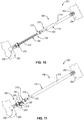
- the first coupling 113 is a threaded rod 213 and the first engagement feature 115 is a sleeve 215.
- the automated drive mechanism 130 is a rotary power generator 230 configured to generate rotary power or torque.
- the rotary power generator 230 is coupled to the base 202 of the nacelle 201 or the engine 203.
- the threaded rod 213 includes a generator interface 270 that is co-rotatably coupled to the rotary power generator 230 to transfer rotary power from the rotary power generator 230 to the threaded rod 213.
- the threaded rod 213 rotates about its longitudinal axis 219, relative to the base 202, in response to receiving the rotary power from the rotary power generator 230. Moreover, as shown in Figure 7 , the threaded rod 213 includes external threads 248 extending along a substantial length of the threaded rod 213. The threaded rod 213 has a maximum outer diameter.
- the sleeve 215 or nut is a hollow tubular element with a length significantly less than the length of the threaded rod 213.
- the sleeve 215 includes internal threads 250 threadably engaged with the external threads 248 of the threaded rod 213.
- the sleeve 215 may include ball bearings or other friction reducing features to facilitate rotational engagement between the sleeve 215 and the threaded rod 213.
- the pitch of the external threads 248 and the internal threads 250 is such that an axially directed load placed on the sleeve 215, such as the compressive load 122, does not induce rotation of the sleeve 215 relative to the threaded rod 213 and thus does not induce translational movement of the sleeve 215 axially along the threaded rod 213.
- the sleeve 215 also includes first interlocking features 240 (e.g., castellated features) formed in an engagement end of the sleeve 215.
- the first interlocking features 240 include a plurality of first tongues 244 and a plurality of first grooves 245.
- Each of the plurality of first grooves 245 is positioned between a corresponding two of the plurality of first tongues 244 such that the first tongues 244 and the first grooves 245 alternate about a circumference of the engagement end of the sleeve 215.
- the second coupling 114 is a hollow tube 214 and the second engagement feature 116 is non-movably coupled to the hollow tube 214.
- the hollow tube 214 is non-rotatably fixed to the door 204 of the nacelle 201 at an upper end portion 252 of the hollow tube 214.
- the upper end portion 252 of the hollow tube 214 can include a bracket, or other coupling, configured to non-rotatably secure the hollow tube 214 to the door 204.
- the second engagement feature 116 is a lower end portion 216 of the hollow tube 214.
- the lower end portion 216 is opposite the upper end portion 252.
- the hollow tube 214 defines a cylindrical channel extending at least a substantial length of the hollow tube 214.
- the cylindrical channel has a minimum inner diameter just greater than the maximum outer diameter of the threaded rod 213.
- the threaded rod 213 extends through the hollow tube 214, along the cylindrical channel, and is rotatable relative to the hollow tube 214 while located within the hollow tube 214.
- the internal surface of the hollow tube 214 defining the cylindrical channel is non-threaded. Accordingly, the hollow tube 214 is not threadably engaged with the external threads of the threaded rod 213 and is configured to translate along (e.g., be slidably engaged with) the threaded rod 213.
- the lower end portion 216 of the hollow tube 214 also includes second interlocking features 242 formed in an engagement end of the hollow tube 214.
- the second interlocking features 242 include a plurality of second tongues 246 and a plurality of second grooves 247.
- Each of the plurality of second grooves 247 is positioned between a corresponding two of the plurality of second tongues 246 such that the second tongues 246 and the second grooves 247 alternate about a circumference of the engagement end of the lower end portion 216 of the hollow tube 214.
- the first tongues 244 of the sleeve 215 are configured to support and engage (e.g., mate with, nestably engage, etc.) corresponding second grooves 247 of the hollow tube 214 and the second tongues 246 of the hollow tube 214 are configured to engage corresponding first grooves 245 of the sleeve 215 to releasably non-rotatably engage the first portion 108 and the second portion 110.
- the interlocking features can be chamfered or rounded to facilitate self-alignment of the interlocking features.
- first interlocking features 140 and the second interlocking features 142 are depicted as alternating and inter-engageable tongues and grooves, in other examples, the first interlocking features 140 and the second interlocking features 142 can be other features that prevent relative rotation when engaged while freely allowing translational disengagement. In contrast, when the first interlocking features 140 and the second interlocking features 142 are not engaged, the sleeve 215 is free to rotate relative to the door 204 and the base 202.
- the retractable component actuator 106 is shown in various stages and modes of operation.
- the retractable component actuator 106 is shown in various stages of the power mode of operation.
- the retractable component actuator 106 is shown in two stages of the manual mode of operation.
- the retractable component actuator 106 is shown in a retracted position corresponding to the door 204 being in a closed position.
- the door 204 applies the compressive load 122 to the retractable component actuator 106 to force the lower end portion 216 of the hollow tube 214 into contact with the sleeve 215, which supports the hollow tube 214 and the door 204.
- the retractable component actuator 106 is extended to open the door 204 by selectively operating the rotary power generator 230 to rotate the threaded rod 213 in a first rotational direction (e.g., counter-clockwise direction) relative to the base 202 and the door 204. Due to engagement between the lower end portion 216 of the hollow tube 214 and the sleeve 215, the sleeve 215 is prevented from rotation relative to the base 202 and the door 204. Accordingly, as the threaded rod 213 rotates in the first rotational direction, the sleeve 215 linearly translates along the threaded rod 213 away from the base 202 in the direction indicated by directional arrow 124.
- a first rotational direction e.g., counter-clockwise direction
- the hollow tube 214 With the hollow tube 214 supported on the sleeve 215, the hollow tube 214 also translates (e.g., slides) along the threaded rod 213 away from the base 202 in the same direction, which causes the door 204 to correspondingly move away from the base 202 and toward an open position.
- the sleeve 215 and hollow tube 214 have translated along the threaded rod 213 to fully extend the retractable component actuator 106 and place the door 204 in the open position. Due to the threaded engagement between the sleeve 215 and the threaded rod 213, the sleeve 215 is temporarily fixed in place on the threaded rod 213, which maintains the door 204 in the open position and allows operators to access the engine 203 protected by the nacelle 201. In fact, the sleeve 215 is effectually temporarily fixed in place at any position along the threaded rod 213 as it translates along the threaded rod 213.
- the door 204 in the power mode, can be closed from a partially open position or the open position by retracting the retractable component actuator 106.
- the retractable component actuator 106 is retracted in the power mode to close the door 204 by selectively operating the rotary power generator 230 to rotate the threaded rod 213 in a second rotational direction (e.g., clockwise direction) relative to the base 202 and the door 204.
- the second rotational direction is opposite the first rotational direction.
- the sleeve 215 linearly translates along the threaded rod 213 toward the base 202 in the direction indicated by directional arrow 162.
- the hollow tube 214 With the hollow tube 214 supported on the sleeve 215, the hollow tube 214 also translates (e.g., slides) along the threaded rod 213 toward the base 202 in the same direction, which causes the door 204 to correspondingly move toward the base 202 and toward the closed position.
- the retractable component actuator 106 is extended to open the door 204 by applying to the door 204 an upward tensile load 126 that is greater than the downward compressive load 122. Because supporting engagement between the lower end portion 216 of the hollow tube 214 and the sleeve 215 does not constrain movement of the hollow tube 214 away from the sleeve 215, the net tensile load applied to the retractable component actuator 106 causes the hollow tube 214 to separate from the sleeve 215 and move the door 204 away from the sleeve 215 and the base 202 in the direction indicated by directional arrow 124.
- the retractable component actuator 106 can be retracted to close the door 204 by decreasing the upward tensile load 126 applied to the door. Decreasing the upward tensile load 126 lowers the hollow tube 214 and the door 204 relative to the base 202 until the hollow tube 214 contacts and is supported on the sleeve 215.
- the first coupling 113 is a chamber housing 313 and the first engagement feature 115 is a first piston 315.
- the first piston 315 is within, translationally movable along, and sealed to the chamber housing 313. More specifically, the chamber housing 313 defines a piston chamber 384 within which the first piston 315 is translationally movable.
- the automated drive mechanism 130 is a linear actuator 330 configured to linearly translate the first piston 315 toward and away from the fixed component 102, which can be the base 202 of the nacelle 201.
- the linear actuator 330 can be any of various linear actuators, such as hydraulically-powered linear actuators, electrically-powered linear actuators, electromagnetically-powered linear actuators, pneumatically-powered linear actuators, and the like.
- the linear actuator 330 is depicted as a hydraulically-powered linear actuator with a hydraulic fluid 382 that is adjustably pressurized to linearly translate the first piston 315 along the chamber housing 313.
- the linear actuator 330 is coupled to the fixed component 102.
- the first piston 315 forms a seal against the piston chamber 384 to prevent leakage of the hydraulic fluid 382 around the first piston 315.
- the first piston 315 includes at least one seal 380 that elastomerically deforms against the interior surface of the piston chamber 384 to form the seal against the piston chamber 384.
- the seal 380 can be any of various seals, such as gaskets, o-rings, etc., that are capable for forming a seal while allowing movement of the seal 380 relative to the surface against which the seal is formed.
- the first piston 315 includes a first engagement surface that is flat in some examples.
- the second coupling 114 is a rod 314 and the second engagement feature 116 is a second piston 316 non-movably coupled to the rod 314.
- the rod 314 is non-rotatably fixed to the retractable component 104, which can be the door 204 of the nacelle 201, at an upper end opposite the lower end coupled to the second piston 316.
- the upper end of the rod 314 can include a bracket, or other coupling, configured to non-rotatably secure the rod 314 to the retractable component 104.
- the second piston 316 is within the piston chamber 384 and translationally movable along the chamber housing 313.
- the second piston 316 includes a second engagement surface that is configured to engage and be supported on (e.g., complements) the first engagement surface of the first piston 315.
- the second engagement surface of the second piston 316 is flat in some examples. Supported engagement between the first piston 315 and the second piston 316 need not prevent relative rotation between the first piston 315 and the second piston 316 in some examples. However, engagement between the first piston 315 and the second piston 316 allows the second piston 316 to be freely movable or separable away from the first piston 315 and the fixed component 102. In other words, the first piston 315 does not constrain movement of the second piston 316 away from the first piston 315 and the fixed component 102 when the second piston 316 is supported on the first piston 315.
- the retractable component actuator 106 is shown operating in the power mode.
- the retractable component 104 applies the compressive load 122 to the retractable component actuator 106 to force the second piston 316 into contact with the first piston 315, which supports the second piston 316, the rod 314, and the retractable component 104.
- the retractable component actuator 106 is extended to actuate the retractable component 104 by selectively operating the linear actuator 330 to move the first piston 315 away from or towards the fixed component 102.
- the second piston 316 and the rod 314 also translate along the chamber housing 313 away from the fixed component 102 in the same direction as the first piston 315, which causes the retractable component 104 to correspondingly move away in the same direction as the first piston 315.
- the retractable component actuator 106 is extended, to move the retractable component 104 away from the fixed component 102 by applying to the retractable component 104 an upward tensile load 126 that is greater than the downward compressive load 122. Because supporting engagement between the first piston 315 and the second piston 316 does not constrain movement of the second piston 316 away from the first piston 315, the net tensile load applied to the retractable component actuator 106 causes the second piston 316 to separate from the first piston 315 and move the retractable component 104 away from the first piston 315 and the fixed component 102 in the direction indicated by directional arrow 124.
- the retractable component actuator 106 of Figure 15 can be retracted to move the retractable component 104 toward the fixed component 102 by decreasing the upward tensile load 126 applied to the retractable component 104. Decreasing the upward tensile load 126 lowers the second piston 316 and the retractable component 104 relative to the fixed component 102 until the second piston 316 contacts and is supported on the first piston 315.
- the retractable component actuator 106 can be selectively switched between the power mode and the manual mode as desired or as is necessary. Generally, in one example, the retractable component actuator 106 will be operated in the power mode unless operation in the manual mode is necessitated, such as due to disablement of the power mode of the retractable component actuator 106.
- the retractable component system 101 is a nacelle of an aircraft and the retractable component 104 is a door of the nacelle, in other embodiments, the retractable component system 101 can be another system of an aircraft and the door can be another door of the aircraft, such as a cargo door.
- instances in this specification where one element is "coupled" to another element can include direct and indirect coupling.
- Direct coupling can be defined as one element coupled to and in some contact with another element.
- Indirect coupling can be defined as coupling between two elements not in direct contact with each other, but having one or more additional elements between the coupled elements.
- securing one element to another element can include direct securing and indirect securing.
- adjacent does not necessarily denote contact. For example, one element can be adjacent another element without being in contact with that element.
- the phrase "at least one of', when used with a list of items, means different combinations of one or more of the listed items may be used and only one of the items in the list may be needed.
- the item may be a particular object, thing, or category.
- "at least one of' means any combination of items or number of items may be used from the list, but not all of the items in the list may be required.
- "at least one of item A, item B, and item C" may mean item A; item A and item B; item B; item A, item B, and item C; or item B and item C.
- "at least one of item A, item B, and item C” may mean, for example, without limitation, two of item A, one of item B, and ten of item C; four of item B and seven of item C; or some other suitable combination.
- first, second, etc. are used herein merely as labels, and are not intended to impose ordinal, positional, or hierarchical requirements on the items to which these terms refer. Moreover, reference to, e.g., a “second” item does not require or preclude the existence of, e.g., a "first” or lower-numbered item, and/or, e.g., a "third" or higher-numbered item.
- a system, apparatus, structure, article, element, component, or hardware “configured to” perform a specified function is indeed capable of performing the specified function without any alteration, rather than merely having potential to perform the specified function after further modification.
- the system, apparatus, structure, article, element, component, or hardware “configured to” perform a specified function is specifically selected, created, implemented, utilized, programmed, and/or designed for the purpose of performing the specified function.
- "configured to” denotes existing characteristics of a system, apparatus, structure, article, element, component, or hardware which enable the system, apparatus, structure, article, element, component, or hardware to perform the specified function without further modification.
- a system, apparatus, structure, article, element, component, or hardware described as being “configured to” perform a particular function may additionally or alternatively be described as being “adapted to” and/or as being “operative to” perform that function.
- the schematic flow chart diagrams included herein are generally set forth as logical flow chart diagrams. As such, the depicted order and labeled steps are indicative of one embodiment of the presented method. Additionally, the format and symbols employed are provided to explain the logical steps of the method and are understood not to limit the scope of the method. Although various arrow types and line types may be employed in the flow chart diagrams, they are understood not to limit the scope of the corresponding method. Indeed, some arrows or other connectors may be used to indicate only the logical flow of the method. For instance, an arrow may indicate a waiting or monitoring period of unspecified duration between enumerated steps of the depicted method. Additionally, the order in which a particular method occurs may or may not strictly adhere to the order of the corresponding steps shown.
Landscapes
- Engineering & Computer Science (AREA)
- General Engineering & Computer Science (AREA)
- Aviation & Aerospace Engineering (AREA)
- Mechanical Engineering (AREA)
- Physics & Mathematics (AREA)
- Fluid Mechanics (AREA)
- Transmission Devices (AREA)
- Power-Operated Mechanisms For Wings (AREA)
Description
- This disclosure relates generally to actuators, and more particularly to a dual mode actuator for opening and closing a door of an engine nacelle of an aircraft.
- External engines of aircraft are protected by nacelles that at least partially encase and protect internal parts of the external engines. Such a nacelle commonly includes one or more cowling doors that are openable to expose internal parts of the external engines for inspection, repair, or maintenance. Because the doors can be heavy, some nacelles include power door opening systems that power-assist the opening and closing of the doors.
- Conventional power door opening systems are prone to jamming or malfunction. Some conventional power door opening systems can be operated manually in the event of jamming or malfunction. For other conventional power door opening systems, extra doors are added to the nacelle to provide access to jammed or malfunctioning systems.
- Manually operating certain conventional power door opening systems can introduce unintended consequences. For example, manually operating a hydraulic actuator may result in the entrainment of air into the hydraulic actuator, which would negative affect the performance of the hydraulic actuator. To prevent the entrainment of air, some conventional power door opening systems added pumps, check valves, and additional fluid, which also added to the cost, complexity, and weight of such systems. Similarly, adding extra doors increases the cost, complexity, and weight of the nacelles.
-
US 2013/312387 A1 , in accordance with its abstract, describes an aircraft nacelle having a fixed structure fixed relative to an aircraft pylon, a translating thrust reverser sleeve translatable aft-ward, relative to the fixed structure, and a translating variable area fan nozzle (VAFN) panel translatable aft-ward, relative to the translating thrust reverser sleeve. The nacelle may also include a VAFN actuator mounted on the translating thrust reverser sleeve and a VAFN drive unit attached to the fixed structure. The VAFN drive unit may be coupled to drive the VAFN actuator via first and second coupling components when the translating thrust reverser sleeve is stowed. When the translating thrust reverser sleeve is deployed, the first and second coupling components may decouple, disconnecting the VAFN drive unit from the VAFN actuator. - The subject matter of the present application has been developed in response to the present state of the art, and in particular, in response to the shortcomings of power door opening systems, that have not yet been fully solved by currently available techniques. Accordingly, the subject matter of the present application has been developed to provide a retractable component actuator and associate method that overcome at least some of the above-discussed shortcomings of prior art techniques. More specifically, in some examples, the retractable component actuator of the present disclosure saves weight, reduces complexity, increases reliability, and reduces maintenance time and cost compared to prior art systems.
- According to the present invention, a retractable component actuator comprises the features of claim 1 and a method of operating a retractable component actuator comprises the steps of claim 12.
- Disclosed herein is a retractable component actuator that comprises a first portion. The first portion is fixable to a fixed component and comprises a first engagement feature. The retractable component actuator also comprises a second portion that is fixable to a retractable component and comprises a second engagement feature releasably supportable on the first engagement feature. The retractable component actuator further comprises an automated drive mechanism operably coupled to the first portion and operable to move the first engagement feature upward and downward relative to the fixed component when the first portion is fixed to the fixed component. Downward movement of the second engagement feature relative to the first engagement feature is constrained by the first engagement feature. Upward movement of the second engagement feature relative to the first engagement feature is unconstrained by the first engagement feature. When the second engagement feature is supported on the first engagement feature and the first portion is fixed to the fixed component, the second engagement feature is upwardly and downwardly co-movable, relative to the fixed component, with the first engagement feature. The preceding subject matter of this paragraph characterizes example 1 of the present disclosure.
- The second engagement feature is biased into supportable contact with the first engagement feature by gravity. The preceding subject matter of this paragraph characterizes example 2 of the present disclosure, wherein example 2 also includes the subject matter according to example 1, above.
- The second engagement feature is freely manually movable upwardly away from the first engagement feature. The preceding subject matter of this paragraph characterizes example 3 of the present disclosure, wherein example 3 also includes the subject matter according to any one of examples 1-2, above.
- When the first portion is fixed to the fixed component, the retractable component actuator is operable in a manual mode and a power mode to move the second engagement feature upwardly away from the fixed component. The manual mode comprises separating the second engagement feature upwardly away from the first engagement feature. The power mode comprises upwardly co-moving the first engagement feature and the second engagement feature via the automated drive mechanism. The preceding subject matter of this paragraph characterizes example 4 of the present disclosure, wherein example 4 also includes the subject matter according to any one of examples 1-3, above.
- The first portion further comprises a threaded rod. The first engagement feature comprises a sleeve threadably engaged with the threaded rod. Rotation of the threaded rod relative to the sleeve translates the sleeve along the threaded rod and moves the sleeve relative to the fixed component when the first portion is fixed to the fixed component. The preceding subject matter of this paragraph characterizes example 5 of the present disclosure, wherein example 5 also includes the subject matter according to any one of examples 1-4, above.
- The second portion comprises a hollow tube. The second engagement feature is non-movably coupled to the hollow tube. The threaded rod extends through and is rotatable relative to the hollow tube. The preceding subject matter of this paragraph characterizes example 6 of the present disclosure, wherein example 6 also includes the subject matter according to example 5, above.
- When the second engagement feature is supported on the first engagement feature, rotation of the threaded rod relative to the sleeve and the hollow tube translates the hollow tube along the threaded rod and moves the threaded rod relative to the fixed component when the first portion is fixed to the fixed component. The preceding subject matter of this paragraph characterizes example 7 of the present disclosure, wherein example 7 also includes the subject matter according to example 6, above.
- The hollow tube is slidably non-threadably engaged with the threaded rod. The preceding subject matter of this paragraph characterizes example 8 of the present disclosure, wherein example 8 also includes the subject matter according to any one of examples 6-7, above.
- When the first portion is fixed to the fixed component and the second portion is fixed to the retractable component, the threaded rod is rotatable relative to the fixed component and the retractable component and the hollow tube is non-rotatable relative to the fixed component and the retractable component. Furthermore, when the second engagement feature is supported on the first engagement feature, the sleeve is non-rotatable relative to the fixed component and the retractable component. The preceding subject matter of this paragraph characterizes example 9 of the present disclosure, wherein example 9 also includes the subject matter according to any one of examples 6-8, above.
- The first engagement feature further comprises first tongues and first grooves formed in the sleeve. The second engagement feature further comprises second tongues and second grooves formed in the hollow tube. The first tongues engage corresponding second grooves and the second tongues engage corresponding first grooves to releasably engage the first portion and the second portion. The preceding subject matter of this paragraph characterizes example 10 of the present disclosure, wherein example 10 also includes the subject matter according to example 9, above.
- Engagement between the first tongues and the second grooves and engagement between the second tongues and the first grooves prevents relative rotation between the sleeve and the hollow tube. The preceding subject matter of this paragraph characterizes example 11 of the present disclosure, wherein example 11 also includes the subject matter according to example 10, above.
- When the second engagement feature is not supported on the first engagement feature, the sleeve is rotatable relative to the fixed component and the retractable component. The preceding subject matter of this paragraph characterizes example 12 of the present disclosure, wherein example 12 also includes the subject matter according to any one of examples 9-11, above.
- The automated drive mechanism comprises a rotary power generator. The preceding subject matter of this paragraph characterizes example 13 of the present disclosure, wherein example 13 also includes the subject matter according to any one of examples 5-12, above.
- The first portion further comprises a chamber housing. The first engagement feature comprises a first piston within, translationally movable along, and sealed to the chamber housing. The second portion further comprises a second piston within and translationally movable along the chamber housing. The second portion further comprise a rod co-movably coupled to the second piston and fixable to the retractable component. The preceding subject matter of this paragraph characterizes example 14 of the present disclosure, wherein example 14 also includes the subject matter according to any one of examples 1-4, above.
- The automated drive mechanism comprises a linear actuator. The preceding subject matter of this paragraph characterizes example 15 of the present disclosure, wherein example 15 also includes the subject matter according to example 14, above.
- Further disclosed herein is a nacelle for an engine of an aircraft. The nacelle comprises a base. The nacelle also comprises a door movably coupled to the base and movable between a closed position and an open position. The nacelle further comprises a retractable component actuator coupled to and extending between the door and at least one of the base and the engine. The retractable component actuator is operable to move the door between the closed position and the open position. The retractable component actuator comprises a first portion fixable to a fixed component and comprising a first engagement feature. The retractable component actuator also comprises a second portion fixable to a retractable component and comprising a second engagement feature releasably supportable on the first engagement feature. The retractable component actuator further comprises an automated drive mechanism operably coupled to the first portion and operable to move the first engagement feature upward and downward relative to the fixed component when the first portion is fixed to the fixed component. Downward movement of the second engagement feature relative to the first engagement feature is constrained by the first engagement feature. Upward movement of the second engagement feature relative to the first engagement feature is unconstrained by the first engagement feature. When the second engagement feature is supported on the first engagement feature and the first portion is fixed to the fixed component, the second engagement feature is upwardly and downwardly co-movable, relative to the fixed component, with the first engagement feature. The preceding subject matter of this paragraph characterizes example 16 of the present disclosure.
- The door applies a downward compressive load onto the second portion. The downward compressive load biases the second engagement feature into supportable contact with the first engagement feature. The preceding subject matter of this paragraph characterizes example 16 of the present disclosure, wherein example 16 also includes the subject matter according to example 17, above.
- Also disclosed herein is a method of actuating a retractable component relative to a fixed component. The method comprises applying a downward compressive load to a second portion of a retractable component actuator to bias a second engagement feature of the second portion into supportable contact with a first engagement feature of a first portion of the retractable component actuator. The method also comprises moving the first engagement feature relative to the fixed component, with the second engagement feature supported on the first engagement feature, to move the second engagement feature and the retractable component relative to the fixed component. The method further comprises applying an upward tensile load, greater than the downward compressive load, to the second portion of the retractable component actuator to separate the second engagement feature from the first engagement feature and move the second engagement feature and the retractable component relative to the first engagement feature and the fixed component. The preceding subject matter of this paragraph characterizes example 18 of the present disclosure.
- The first portion further comprises a threaded rod. The first engagement feature comprises a sleeve threadably engaged with the threaded rod. The second portion comprises a hollow tube fixed to the retractable component. The second engagement feature is non-movably coupled to the hollow tube. The threaded rod extends through and is rotatable relative to the hollow tube. Moving the first engagement feature relative to the fixed component comprises rotating the threaded rod relative to the sleeve to translate the sleeve and the hollow tube along the threaded rod. The preceding subject matter of this paragraph characterizes example 19 of the present disclosure, wherein example 19 also includes the subject matter according to example 18, above.
- The first portion further comprises a chamber housing. The first engagement feature comprises a first piston within, translationally movable along, and sealed to the chamber housing. The second portion further comprises a second piston within and translationally movable along the chamber housing. The second portion further comprises a rod co-movably coupled to the second piston and fixed to the retractable component. Moving the first engagement feature relative to the fixed component comprises hydraulically driving the first piston and the second piston along the chamber housing. The preceding subject matter of this paragraph characterizes example 20 of the present disclosure, wherein example 20 also includes the subject matter according to example 18, above.
- The described features, structures, advantages, and/or characteristics of the subject matter of the present disclosure may be combined in any suitable manner in one or more embodiments and/or implementations. In the following description, numerous specific details are provided to impart a thorough understanding of embodiments of the subject matter of the present disclosure. One skilled in the relevant art will recognize that the subject matter of the present disclosure may be practiced without one or more of the specific features, details, components, materials, and/or methods of a particular embodiment or implementation. In other instances, additional features and advantages may be recognized in certain embodiments and/or implementations that may not be present in all embodiments or implementations. Further, in some instances, well-known structures, materials, or operations are not shown or described in detail to avoid obscuring aspects of the subject matter of the present disclosure. The features and advantages of the subject matter of the present disclosure will become more fully apparent from the following description and appended claims, or may be learned by the practice of the subject matter as set forth hereinafter.
- Further, the disclosure comprises embodiments according to the following paragraphs:
- 1. A retractable component actuator, comprises:
- a first portion fixable to a fixed component and comprising a first engagement feature;
- a second portion fixable to a retractable component and comprising a second engagement feature releasably supportable on the first engagement feature; and
- an automated drive mechanism operably coupled to the first portion and operable to move the first engagement feature upward and downward relative to the fixed component when the first portion is fixed to the fixed component;
- wherein:
- downward movement of the second engagement feature relative to the first engagement feature is constrained by the first engagement feature;
- upward movement of the second engagement feature relative to the first engagement feature is unconstrained by the first engagement feature; and
- when the second engagement feature is supported on the first engagement feature and the first portion is fixed to the fixed component, the second engagement feature is upwardly and downwardly co-movable, relative to the fixed component, with the first engagement feature.
- 2. In the retractable component actuator according to paragraph 1, the second engagement feature is biased into supportable contact with the first engagement feature by gravity.
- 3. In the retractable component actuator according to paragraphs 1-2, the second engagement feature is freely manually movable upwardly away from the first engagement feature.
- 4. In the retractable component actuator according to paragraphs 1-3,
when the first portion is fixed to the fixed component, the retractable component actuator is operable in a manual mode and a power mode to move the second engagement feature upwardly away from the fixed component;
the manual mode comprises separating the second engagement feature upwardly away from the first engagement feature; and
the power mode comprises upwardly co-moving the first engagement feature and the second engagement feature via the automated drive mechanism. - 5. In the retractable component actuator according to paragraphs 1-4,
the first portion further comprises a threaded rod; and
the first engagement feature comprises a sleeve threadably engaged with the threaded rod; and
rotation of the threaded rod relative to the sleeve translates the sleeve along the threaded rod and moves the sleeve relative to the fixed component when the first portion is fixed to the fixed component. - 6. In the retractable component actuator according to paragraph 5,
the second portion comprises a hollow tube;
the second engagement feature is non-movably coupled to the hollow tube; and
the threaded rod extends through and is rotatable relative to the hollow tube. - 7. In the retractable component actuator according to paragraph 6, when the second engagement feature is supported on the first engagement feature, rotation of the threaded rod relative to the sleeve and the hollow tube translates the hollow tube along the threaded rod and moves the threaded rod relative to the fixed component when the first portion is fixed to the fixed component.
- 8. In the retractable component actuator according to paragraph 6, the hollow tube is slidably non-threadably engaged with the threaded rod.
- 9. In the retractable component actuator according to paragraph 6, when the first portion is fixed to the fixed component and the second portion is fixed to the retractable component:
- the threaded rod is rotatable relative to the fixed component and the retractable component;
- the hollow tube is non-rotatable relative to the fixed component and the retractable component; and
- when the second engagement feature is supported on the first engagement feature, the sleeve is non-rotatable relative to the fixed component and the retractable component.
- 10. In the retractable component actuator according to paragraph 9,
the first engagement feature further comprises first tongues and first grooves formed in the sleeve;
the second engagement feature further comprises second tongues and second grooves formed in the hollow tube; and
the first tongues engage corresponding second grooves and the second tongues engage corresponding first grooves to releasably engage the first portion and the second portion. - 11. In the retractable component actuator according to paragraph 10, engagement between the first tongues and the second grooves and engagement between the second tongues and the first grooves prevents relative rotation between the sleeve and the hollow tube.
- 12. In the retractable component actuator according to paragraph 9, when the second engagement feature is not supported on the first engagement feature, the sleeve is rotatable relative to the fixed component and the retractable component.
- 13. In the retractable component actuator according to paragraph 5, the automated drive mechanism comprises a rotary power generator.
- 14. In the retractable component actuator according to paragraph 1,
the first portion further comprises a chamber housing;
the first engagement feature comprises a first piston within, translationally movable along, and sealed to the chamber housing;
the second portion further comprises a second piston within and translationally movable along the chamber housing; and
the second portion further comprise a rod co-movably coupled to the second piston and fixable to the retractable component. - 15. In the retractable component actuator according to paragraph 14, the automated drive mechanism comprises a linear actuator.
- 16. A nacelle for an engine of an aircraft comprises:
- a base;
- a door movably coupled to the base and movable between a closed position and an open position;
- a retractable component actuator coupled to and extending between the door and at least one of the base and the engine, the retractable component actuator is operable to move the door between the closed position and the open position, wherein the retractable component actuator comprises:
- a first portion fixable to a fixed component and comprising a first engagement feature;
- a second portion fixable to a retractable component and comprising a second engagement feature releasably supportable on the first engagement feature; and
- an automated drive mechanism operably coupled to the first portion and operable to move the first engagement feature upward and downward relative to the fixed component when the first portion is fixed to the fixed component;
- wherein:
- downward movement of the second engagement feature relative to the first engagement feature is constrained by the first engagement feature;
- upward movement of the second engagement feature relative to the first engagement feature is unconstrained by the first engagement feature; and
- when the second engagement feature is supported on the first engagement feature and the first portion is fixed to the fixed component, the second engagement feature is upwardly and downwardly co-movable, relative to the fixed component, with the first engagement feature.
- 17. In the nacelle according to paragraph 16,
the door applies a downward compressive load onto the second portion; and
the downward compressive load biases the second engagement feature into supportable contact with the first engagement feature. - 18. A method of actuating a retractable component relative to a fixed component comprises:
- applying a downward compressive load to a second portion of a retractable component actuator to bias a second engagement feature of the second portion into supportable contact with a first engagement feature of a first portion of the retractable component actuator;
- moving the first engagement feature relative to the fixed component, with the second engagement feature supported on the first engagement feature, to move the second engagement feature and the retractable component relative to the fixed component; and
- applying an upward tensile load, greater than the downward compressive load, to the second portion of the retractable component actuator to separate the second engagement feature from the first engagement feature and move the second engagement feature and the retractable component relative to the first engagement feature and the fixed component.
- 19. In the method according to paragraph 18,
the first portion further comprises a threaded rod;
the first engagement feature comprises a sleeve threadably engaged with the threaded rod;
the second portion comprises a hollow tube fixed to the retractable component;
the second engagement feature is non-movably coupled to the hollow tube;
the threaded rod extends through and is rotatable relative to the hollow tube; and
moving the first engagement feature relative to the fixed component comprises rotating the threaded rod relative to the sleeve to translate the sleeve and the hollow tube along the threaded rod. - 20. In the method according to paragraph 18,
the first portion further comprises a chamber housing;- the first engagement feature comprises a first piston within, translationally movable along, and sealed to the chamber housing;
- the second portion further comprises a second piston within and translationally movable along the chamber housing;
- the second portion further comprises a rod co-movably coupled to the second piston and fixed to the retractable component; and
- moving the first engagement feature relative to the fixed component comprises hydraulically driving the first piston and the second piston along the chamber housing.
- In order that the advantages of the subject matter may be more readily understood, a more particular description of the subject matter briefly described above will be rendered by reference to specific embodiments that are illustrated in the appended drawings. Understanding that these drawings depict only typical embodiments of the subject matter and are not therefore to be considered to be limiting of its scope, the subject matter will be described and explained with additional specificity and detail through the use of the drawings, in which:
-
Figure 1 is a schematic block diagram of an aircraft with a retractable component system, according to one or more examples of the present disclosure; -
Figure 2 is a schematic block diagram of the aircraft ofFigure 1 , shown operating in a power mode, according to one or more examples of the present disclosure; -
Figure 3 is a schematic block diagram of the aircraft ofFigure 1 , shown operating in a manual mode, according to one or more examples of the present disclosure; -
Figure 4 is a perspective view of a nacelle of an aircraft, according to one or more examples of the present disclosure; -
Figure 5 is a front view of a nacelle of an aircraft, according to one or more examples of the present disclosure; -
Figure 6 is a perspective view of a portion of a retractable component actuator, according to one or more examples of the present disclosure; -
Figure 7 is a cross-sectional perspective view of the portion of the retractable component actuator ofFigure 6 , taken along the line 7-7 ofFigure 6 , according to one or more examples of the present disclosure; -
Figure 8 is a perspective view of a nacelle of an aircraft, with a retractable component actuator in a retracted position, according to one or more examples of the present disclosure; -
Figure 9 is a perspective view of the nacelle ofFigure 8 , with the retractable component actuator in an intermediate position, according to one or more examples of the present disclosure; -
Figure 10 is a perspective view of the nacelle ofFigure 8 , with the retractable component actuator in an extended position, according to one or more examples of the present disclosure; -
Figure 11 is a perspective view of the nacelle ofFigure 8 , with the retractable component actuator in an intermediate position, according to one or more examples of the present disclosure; -
Figure 12 is a perspective view of the nacelle ofFigure 8 , with the retractable component actuator operating in a manual mode and a retractable component in a partially open position, according to one or more examples of the present disclosure; -
Figure 13 is a perspective view of the nacelle ofFigure 8 , with the retractable component actuator operating in a manual mode and the retractable component in an open position, according to one or more examples of the present disclosure; -
Figure 14 is a cross-sectional perspective view of a retractable component actuator, shown operating in a power mode, according to one or more examples of the present disclosure; -
Figure 15 is a cross-sectional perspective view of the retractable component actuator ofFigure 14 , shown operating in a manual mode, according to one or more examples of the present disclosure; and -
Figure 16 is a schematic flow chart of a method of actuating a retractable component, according to one or more examples of the present disclosure. - Reference throughout this specification to "one embodiment," "an embodiment," or similar language means that a particular feature, structure, or characteristic described in connection with the embodiment is included in at least one embodiment of the present disclosure. Appearances of the phrases "in one embodiment," "in an embodiment," and similar language throughout this specification may, but do not necessarily, all refer to the same embodiment. Similarly, the use of the term "implementation" means an implementation having a particular feature, structure, or characteristic described in connection with one or more embodiments of the present disclosure, however, absent an express correlation to indicate otherwise, an implementation may be associated with one or more embodiments.
- Referring to
Figures 1-3 , according to some embodiments, aretractable component system 101 includes a fixedcomponent 102 and aretractable component 104. Theretractable component 104 is actuatable (e.g., movable) between a first position (e.g., closed position) and a second position (e.g., open position) relative to the fixedcomponent 102. Actuation of theretractable component 104 is facilitated by a retractable component actuator 106 (i.e., dual mode actuator) coupled to and extending between the fixedcomponent 102 and theretractable component 104. Theretractable component system 101 can be a sub-system of another system. For example, theretractable component system 101 can form part of anaircraft 100. In other example, theretractable component system 101 forms part of another type of mobile structure, such as an automobile, watercraft, spacecraft, and the like. According to some examples, theretractable component system 101 forms part of a non-mobile structure, such as a building, machinery, and the like. - The fixed
component 102 is fixed relative to theretractable component 104. In other words, the fixedcomponent 102 is fixed because theretractable component 104 is movable relative to the fixedcomponent 102. Accordingly, the fixedcomponent 102 need not be a stationary object, such as a part of a building, but can be a movable object, such as a component on an aircraft. - The
retractable component 104 may be directly or indirectly movably coupled to the fixedcomponent 102. For example, theretractable component 104 can be hingedly coupled to the fixedcomponent 102, such as a door being hingedly coupled to a panel. However, in some examples, theretractable component 104 is movably coupled to the fixedcomponent 102 via one or more components interconnecting theretractable component 104 and the fixedcomponent 102. - The
retractable component 104 is also interconnected to the fixedcomponent 102 by theretractable component actuator 106. Generally, theretractable component actuator 106 is configured and selectively operable to move theretractable component 104 relative to the fixedcomponent 102. - The
retractable component actuator 106 includes afirst portion 108 that is fixable (e.g., configured to be fixed) to the fixedcomponent 102. Thefirst portion 108 includes afirst coupling 113 and afirst engagement feature 115. Thefirst coupling 113 is coupled to the fixedcomponent 102 and thefirst engagement feature 115 is coupled to thefirst coupling 113. In this manner, thefirst engagement feature 115 is coupled to the fixedcomponent 102. - The
retractable component actuator 106 also includes asecond portion 110 that is fixable to theretractable component 104. Thesecond portion 110 includes asecond coupling 114 and asecond engagement feature 116. Thesecond coupling 114 is coupled to theretractable component 104 and thesecond engagement feature 116 is coupled to thesecond coupling 114. In this manner, thesecond engagement feature 116 is coupled to theretractable component 104. Thesecond coupling 114 is co-movably coupled to theretractable component 104, when fixed to theretractable component 104, such that movement of thesecond coupling 114 results in movement of theretractable component 104. - The
retractable component system 101 is configured to apply acompressive load 122, from theretractable component 104 towards the fixedcomponent 102, to thesecond portion 110. Thecompressive load 122 biases or urges thesecond engagement feature 116 into supportable contact with thefirst engagement feature 115. Thesecond portion 110 of theretractable component actuator 106 is freely movable away from and toward thefirst portion 108 within a range partially constrained by thefirst engagement feature 115. More specifically, thefirst engagement feature 115 constrains movement of thesecond portion 110 toward thefirst portion 108 but does not constrain movement of thesecond portion 110 away from thefirst portion 108. In some examples, theretractable component 104 is positioned above theretractable component actuator 106 and the source of thecompressive load 122 is the weight of theretractable component 104 bearing down on theretractable component actuator 106. In other words, thesecond engagement feature 116 is biased into supportable contact with thefirst engagement feature 115 by gravity. According to such examples, movement of thesecond portion 110 toward the first portion 108 (e.g., downward movement) is constrained by thefirst engagement feature 115; and movement of thesecond portion 110 away from the first portion 108 (e.g., upward movement) is unconstrained by thefirst engagement feature 115. - The
first engagement feature 115 constrains movement of thesecond portion 110 toward thefirst portion 108 by contacting and stopping thesecond engagement feature 116. When movement of thesecond portion 110 toward thefirst portion 108 is a downward movement, thefirst engagement feature 115 constrains movement of thesecond portion 110 toward thefirst portion 108 by supporting thesecond engagement feature 116 on thefirst engagement feature 115. Because the upward movement, or movement of thesecond portion 110 away from thefirst portion 108, is unconstrained by thefirst engagement feature 115, but downward movement, or movement of thesecond portion 110 toward thefirst portion 108, is constrained via contact with thefirst engagement feature 115, thesecond engagement feature 116 can be defined as being releasably supportable on thefirst engagement feature 115. - When the
second engagement feature 116 is supported on (e.g., in supportable contact with) thefirst engagement feature 115 and thefirst portion 108 is fixed to the fixedcomponent 102, thesecond portion 110, and thus thesecond engagement feature 116, is upwardly and downwardly co-movable, relative to the fixedcomponent 102, with thefirst engagement feature 115. In other words, when thesecond engagement feature 116 is supported on thefirst engagement feature 115, upward movement of thefirst engagement feature 115 results in upward movement of thesecond engagement feature 116 and thus thesecond coupling 114. In contrast, when thesecond engagement feature 116 is supported on thefirst engagement feature 115, downward movement of thefirst engagement feature 115 results in downward movement of thesecond engagement feature 116 and thus thesecond coupling 114. - Movement of the
first engagement feature 115 relative to the fixedcomponent 102 is facilitated by an automated drive mechanism 130 of theretractable component actuator 106. In other words, the automated drive mechanism 130 is operable to move (e.g., upwardly and downwardly) thefirst engagement feature 115 of thefirst portion 108 relative to the fixedcomponent 102. The automated drive mechanism 130 is operably coupled to thefirst portion 108. For example, the automated drive mechanism 130 can be indirectly coupled to thefirst engagement feature 115, such as via thefirst coupling 113, or directly coupled to thefirst engagement feature 115. In some implementations, the automated drive mechanism 130 is coupled to the fixedcomponent 102. For example, the automated drive mechanism 130 is fixedly coupled to or integrated into the fixedcomponent 102. However, in other examples, the automated drive mechanism 130 is separate from the fixedcomponent 102. - As presented, when supported on the
first engagement feature 115, movement of thesecond engagement feature 116 is driven by movement of thefirst engagement feature 115. However, while supportable contact between thefirst engagement feature 115 and thesecond engagement feature 116 ensures thesecond engagement feature 116 moves when thefirst engagement feature 115 moves and separation of thesecond engagement feature 116 downwardly away from thefirst engagement feature 115 is prevented, such supportable contact does not prevent thesecond engagement feature 116 from separating upwardly away from thefirst engagement feature 115. Accordingly, thesecond engagement feature 116 is freely movable (e.g., via manual or assisted power) upwardly away from thefirst engagement feature 115. Therefore, thesecond engagement feature 116 and thus theretractable component 104 can be freely moved upwardly away from the fixedcomponent 102 independent of operation of the automated drive mechanism 130. - In view of the foregoing, the
retractable component actuator 106 is operable in a power mode and a manual mode to move thesecond engagement feature 116 and theretractable component 104 relative to the fixedcomponent 102. Because theretractable component actuator 106 is operable in a power mode and a manual mode, theretractable component actuator 106 is considered a dual mode actuator. Referring toFigures 1 and2 , in the power mode, thecompressive load 122 is sufficient that there is a net compressive force acting on thesecond portion 110. The net compressive force resulting from thecompressive load 122 forces thesecond engagement feature 116 to be supported on (or placed into supportable contact with) thefirst engagement feature 115. In the power mode, movement of thesecond engagement feature 116 is achieved by moving thefirst engagement feature 115 via operation of the automated drive mechanism 130. The automated drive mechanism 130 is operable to extend or raise, as indicated bydirectional arrow 124, thefirst engagement feature 115 and thesecond engagement feature 116. Additionally, the automated drive mechanism 130 is operable to retract or lower, in a direction opposite thedirectional arrow 124, thefirst engagement feature 115 and thesecond engagement feature 116. Operation of the automated drive mechanism 130 can be controlled manually or automatically via a controller onboard theaircraft 100, near theaircraft 100, or remote from theaircraft 100. - Referring to
Figure 3 , in the manual mode, a net tensile force is acting on thesecond portion 110. In some examples, because thecompressive load 122, generated by some portion of the weight of theretractable component 104, is constant, the net tensile force is created by applying an upwardtensile load 126 to thesecond portion 110 that is greater than thecompressive load 122. Because the contact or engagement between thefirst engagement feature 115 and thesecond engagement feature 116 does not constrain movement of thesecond engagement feature 116 upwardly away from thefirst engagement feature 115, once the upwardtensile load 126 exceeds thecompressive load 122 and a net tensile force is acting on thesecond portion 110, thesecond engagement feature 116 separates upwardly away from thefirst engagement feature 115. Such upward separation of thesecond engagement feature 116 results in theretractable component 104 being raised upwardly relative to the fixedcomponent 102, as indicated bydirectional arrow 124, without operation of the automated drive mechanism 130 and movement of thefirst engagement feature 115. When separated, the upwardtensile load 126 can also be decreased to reduce the net tensile force and lower thesecond engagement feature 116, and thus theretractable component 104, toward thefirst engagement feature 115, and thus the fixedcomponent 102. - In the manual mode, the tensile load is generated by a power source other than the automated drive mechanism 130. The power source can be a manual power source, such as one or more human operators. Alternatively, the power source can be a non-manual power source, such as a forklift, jack, or other lifting tool.
- According to some examples, the
retractable component actuator 106 is operated in the power mode to raise (e.g., open) and lower (e.g., close) theretractable component 104 as long as thefirst portion 108 and the automated drive mechanism 130 are operating properly. Should either of thefirst portion 108 or the automated drive mechanism 130 malfunction, operation of theretractable component actuator 106 can be switched to the manual mode to raise and lower theretractable component 104 by effectually bypassing thefirst portion 108 and automated drive mechanism 130. Thefirst portion 108 and the automated drive mechanism 130 experience a malfunction in a variety of ways, such as binding of thefirst engagement feature 115, disablement of the automated drive mechanism 130, power loss to the automated drive mechanism 130, and the like. - Referring to
Figure 16 , according to one embodiment, amethod 400 of actuating theretractable component 104 relative to the fixedcomponent 102 includes applying a downwardcompressive load 122 to thesecond portion 110 of theretractable component actuator 106 to bias thesecond engagement feature 116 of thesecond portion 110 into supportable contact with thefirst engagement feature 115 of thefirst portion 108 of theretractable component actuator 106 at 402. Themethod 400 also includes moving thefirst engagement feature 115 relative to the fixedcomponent 102, with thesecond engagement feature 116 supported on thefirst engagement feature 115, to move thesecond engagement feature 116 and theretractable component 104 relative to the fixedcomponent 102 at 404. Themethod 400 additionally includes applying the upwardtensile load 126, which is greater than the downwardcompressive load 122, to thesecond portion 110 of theretractable component actuator 106 to separate thesecond engagement feature 116 from thefirst engagement feature 115 and move thesecond engagement feature 116 and theretractable component 104 relative to thefirst engagement feature 115 and the fixedcomponent 102 at 406. - Referring to
Figures 4 and 5 , in some embodiments, theretractable component system 101 is anacelle 201 for anengine 203 of theaircraft 100. Thenacelle 201 is a streamlined housing or casing around at least a portion of theengine 203. The fixedcomponent 102 can be a base 202 and anengine 203 of thenacelle 201 and theretractable component 104 can be a door 204 (e.g., cowling door) of thenacelle 201. Thedoor 204 is hingedly coupled to thebase 202 and is movable between a closed position and an open position (as shown). When thedoor 204 is in the open position, theengine 203 is accessible through an opening in thebase 202, which is now uncovered with thedoor 204 in the open position. Theretractable component actuator 106 is a retractable component actuator of thenacelle 201 and is coupled to and extends between thedoor 204 and at least one ofbase 202 or theengine 203. In some implementations, thenacelle 201 includes more than oneretractable component actuator 106 between the engine 203 (and/or base 202) and adoor 204 of thenacelle 201. Thenacelle 201 may includemultiple doors 204 and multipleretractable component actuators 106 each coupled to the engine 203 (and/or base 202) and a corresponding one of thedoors 204. - Now referring to
Figures 6-13 , according to one embodiment of theretractable component actuator 106 forming part of thenacelle 201, thefirst coupling 113 is a threadedrod 213 and thefirst engagement feature 115 is asleeve 215. The automated drive mechanism 130 is arotary power generator 230 configured to generate rotary power or torque. Therotary power generator 230 is coupled to thebase 202 of thenacelle 201 or theengine 203. The threadedrod 213 includes agenerator interface 270 that is co-rotatably coupled to therotary power generator 230 to transfer rotary power from therotary power generator 230 to the threadedrod 213. The threadedrod 213 rotates about itslongitudinal axis 219, relative to thebase 202, in response to receiving the rotary power from therotary power generator 230. Moreover, as shown inFigure 7 , the threadedrod 213 includesexternal threads 248 extending along a substantial length of the threadedrod 213. The threadedrod 213 has a maximum outer diameter. - The
sleeve 215 or nut is a hollow tubular element with a length significantly less than the length of the threadedrod 213. Thesleeve 215 includesinternal threads 250 threadably engaged with theexternal threads 248 of the threadedrod 213. Thesleeve 215 may include ball bearings or other friction reducing features to facilitate rotational engagement between thesleeve 215 and the threadedrod 213. The pitch of theexternal threads 248 and theinternal threads 250 is such that an axially directed load placed on thesleeve 215, such as thecompressive load 122, does not induce rotation of thesleeve 215 relative to the threadedrod 213 and thus does not induce translational movement of thesleeve 215 axially along the threadedrod 213. Thesleeve 215 also includes first interlocking features 240 (e.g., castellated features) formed in an engagement end of thesleeve 215. In one example, the first interlocking features 240 include a plurality offirst tongues 244 and a plurality offirst grooves 245. Each of the plurality offirst grooves 245 is positioned between a corresponding two of the plurality offirst tongues 244 such that thefirst tongues 244 and thefirst grooves 245 alternate about a circumference of the engagement end of thesleeve 215. - The
second coupling 114 is ahollow tube 214 and thesecond engagement feature 116 is non-movably coupled to thehollow tube 214. Thehollow tube 214 is non-rotatably fixed to thedoor 204 of thenacelle 201 at anupper end portion 252 of thehollow tube 214. Theupper end portion 252 of thehollow tube 214 can include a bracket, or other coupling, configured to non-rotatably secure thehollow tube 214 to thedoor 204. In the illustrated example, thesecond engagement feature 116 is alower end portion 216 of thehollow tube 214. Thelower end portion 216 is opposite theupper end portion 252. Thehollow tube 214 defines a cylindrical channel extending at least a substantial length of thehollow tube 214. The cylindrical channel has a minimum inner diameter just greater than the maximum outer diameter of the threadedrod 213. Moreover, the threadedrod 213 extends through thehollow tube 214, along the cylindrical channel, and is rotatable relative to thehollow tube 214 while located within thehollow tube 214. The internal surface of thehollow tube 214 defining the cylindrical channel is non-threaded. Accordingly, thehollow tube 214 is not threadably engaged with the external threads of the threadedrod 213 and is configured to translate along (e.g., be slidably engaged with) the threadedrod 213. - The
lower end portion 216 of thehollow tube 214 also includes second interlocking features 242 formed in an engagement end of thehollow tube 214. In one example, the second interlocking features 242 (e.g., castellated features) include a plurality ofsecond tongues 246 and a plurality ofsecond grooves 247. Each of the plurality ofsecond grooves 247 is positioned between a corresponding two of the plurality ofsecond tongues 246 such that thesecond tongues 246 and thesecond grooves 247 alternate about a circumference of the engagement end of thelower end portion 216 of thehollow tube 214. - The
first tongues 244 of thesleeve 215 are configured to support and engage (e.g., mate with, nestably engage, etc.) correspondingsecond grooves 247 of thehollow tube 214 and thesecond tongues 246 of thehollow tube 214 are configured to engage correspondingfirst grooves 245 of thesleeve 215 to releasably non-rotatably engage thefirst portion 108 and thesecond portion 110. The interlocking features can be chamfered or rounded to facilitate self-alignment of the interlocking features. In other words, engagement between the first interlocking features 140 of thesleeve 215 and the second interlocking features 142 of thehollow tube 214, when thehollow tube 214 is supported on thesleeve 215, prevents relative rotation between thesleeve 215 and thehollow tube 214. Accordingly, because thedoor 204 prevents thehollow tube 214 from rotating relative to thedoor 204 and thebase 202, engagement between the first interlocking features 140 of thesleeve 215 and the second interlocking features 142 of thehollow tube 214 prevents rotation of thesleeve 215 relative to thedoor 204 and thebase 202. Although the first interlocking features 140 and the second interlocking features 142 are depicted as alternating and inter-engageable tongues and grooves, in other examples, the first interlocking features 140 and the second interlocking features 142 can be other features that prevent relative rotation when engaged while freely allowing translational disengagement. In contrast, when the first interlocking features 140 and the second interlocking features 142 are not engaged, thesleeve 215 is free to rotate relative to thedoor 204 and thebase 202. - Referring in particular to
Figures 8-13 , theretractable component actuator 106 is shown in various stages and modes of operation. InFigures 8-11 , theretractable component actuator 106 is shown in various stages of the power mode of operation. In contrast, inFigures 12 and 13 , theretractable component actuator 106 is shown in two stages of the manual mode of operation. - Referring to
Figure 8 , theretractable component actuator 106 is shown in a retracted position corresponding to thedoor 204 being in a closed position. Thedoor 204 applies thecompressive load 122 to theretractable component actuator 106 to force thelower end portion 216 of thehollow tube 214 into contact with thesleeve 215, which supports thehollow tube 214 and thedoor 204. - Now referring to
Figure 9 , in the power mode, theretractable component actuator 106 is extended to open thedoor 204 by selectively operating therotary power generator 230 to rotate the threadedrod 213 in a first rotational direction (e.g., counter-clockwise direction) relative to thebase 202 and thedoor 204. Due to engagement between thelower end portion 216 of thehollow tube 214 and thesleeve 215, thesleeve 215 is prevented from rotation relative to thebase 202 and thedoor 204. Accordingly, as the threadedrod 213 rotates in the first rotational direction, thesleeve 215 linearly translates along the threadedrod 213 away from the base 202 in the direction indicated bydirectional arrow 124. With thehollow tube 214 supported on thesleeve 215, thehollow tube 214 also translates (e.g., slides) along the threadedrod 213 away from the base 202 in the same direction, which causes thedoor 204 to correspondingly move away from thebase 202 and toward an open position. - As shown in
Figure 10 , thesleeve 215 andhollow tube 214 have translated along the threadedrod 213 to fully extend theretractable component actuator 106 and place thedoor 204 in the open position. Due to the threaded engagement between thesleeve 215 and the threadedrod 213, thesleeve 215 is temporarily fixed in place on the threadedrod 213, which maintains thedoor 204 in the open position and allows operators to access theengine 203 protected by thenacelle 201. In fact, thesleeve 215 is effectually temporarily fixed in place at any position along the threadedrod 213 as it translates along the threadedrod 213. - Referring to
Figure 11 , in the power mode, thedoor 204 can be closed from a partially open position or the open position by retracting theretractable component actuator 106. Theretractable component actuator 106 is retracted in the power mode to close thedoor 204 by selectively operating therotary power generator 230 to rotate the threadedrod 213 in a second rotational direction (e.g., clockwise direction) relative to thebase 202 and thedoor 204. The second rotational direction is opposite the first rotational direction. As the threadedrod 213 rotates in the second rotational direction, thesleeve 215 linearly translates along the threadedrod 213 toward the base 202 in the direction indicated bydirectional arrow 162. With thehollow tube 214 supported on thesleeve 215, thehollow tube 214 also translates (e.g., slides) along the threadedrod 213 toward the base 202 in the same direction, which causes thedoor 204 to correspondingly move toward thebase 202 and toward the closed position. - Now referring to
Figures 12 and 13 , in the manual mode, theretractable component actuator 106 is extended to open thedoor 204 by applying to thedoor 204 an upwardtensile load 126 that is greater than the downwardcompressive load 122. Because supporting engagement between thelower end portion 216 of thehollow tube 214 and thesleeve 215 does not constrain movement of thehollow tube 214 away from thesleeve 215, the net tensile load applied to theretractable component actuator 106 causes thehollow tube 214 to separate from thesleeve 215 and move thedoor 204 away from thesleeve 215 and the base 202 in the direction indicated bydirectional arrow 124. Although not shown, in the manual mode, theretractable component actuator 106 can be retracted to close thedoor 204 by decreasing the upwardtensile load 126 applied to the door. Decreasing the upwardtensile load 126 lowers thehollow tube 214 and thedoor 204 relative to the base 202 until thehollow tube 214 contacts and is supported on thesleeve 215. - Referring to
Figures 14 and 15 , according to another embodiment of theretractable component actuator 106, thefirst coupling 113 is achamber housing 313 and thefirst engagement feature 115 is afirst piston 315. Thefirst piston 315 is within, translationally movable along, and sealed to thechamber housing 313. More specifically, thechamber housing 313 defines apiston chamber 384 within which thefirst piston 315 is translationally movable. The automated drive mechanism 130 is alinear actuator 330 configured to linearly translate thefirst piston 315 toward and away from the fixedcomponent 102, which can be thebase 202 of thenacelle 201. Thelinear actuator 330 can be any of various linear actuators, such as hydraulically-powered linear actuators, electrically-powered linear actuators, electromagnetically-powered linear actuators, pneumatically-powered linear actuators, and the like. In the illustrated example, thelinear actuator 330 is depicted as a hydraulically-powered linear actuator with ahydraulic fluid 382 that is adjustably pressurized to linearly translate thefirst piston 315 along thechamber housing 313. Thelinear actuator 330 is coupled to the fixedcomponent 102. - In the illustrated embodiment, the
first piston 315 forms a seal against thepiston chamber 384 to prevent leakage of thehydraulic fluid 382 around thefirst piston 315. In some examples, thefirst piston 315 includes at least oneseal 380 that elastomerically deforms against the interior surface of thepiston chamber 384 to form the seal against thepiston chamber 384. Theseal 380 can be any of various seals, such as gaskets, o-rings, etc., that are capable for forming a seal while allowing movement of theseal 380 relative to the surface against which the seal is formed. Thefirst piston 315 includes a first engagement surface that is flat in some examples. - In the embodiment of
Figures 14 and 15 , thesecond coupling 114 is arod 314 and thesecond engagement feature 116 is asecond piston 316 non-movably coupled to therod 314. Therod 314 is non-rotatably fixed to theretractable component 104, which can be thedoor 204 of thenacelle 201, at an upper end opposite the lower end coupled to thesecond piston 316. The upper end of therod 314 can include a bracket, or other coupling, configured to non-rotatably secure therod 314 to theretractable component 104. Thesecond piston 316 is within thepiston chamber 384 and translationally movable along thechamber housing 313. Thesecond piston 316 includes a second engagement surface that is configured to engage and be supported on (e.g., complements) the first engagement surface of thefirst piston 315. The second engagement surface of thesecond piston 316 is flat in some examples. Supported engagement between thefirst piston 315 and thesecond piston 316 need not prevent relative rotation between thefirst piston 315 and thesecond piston 316 in some examples. However, engagement between thefirst piston 315 and thesecond piston 316 allows thesecond piston 316 to be freely movable or separable away from thefirst piston 315 and the fixedcomponent 102. In other words, thefirst piston 315 does not constrain movement of thesecond piston 316 away from thefirst piston 315 and the fixedcomponent 102 when thesecond piston 316 is supported on thefirst piston 315. - In
Figure 14 , theretractable component actuator 106 is shown operating in the power mode. Theretractable component 104 applies thecompressive load 122 to theretractable component actuator 106 to force thesecond piston 316 into contact with thefirst piston 315, which supports thesecond piston 316, therod 314, and theretractable component 104. Theretractable component actuator 106 is extended to actuate theretractable component 104 by selectively operating thelinear actuator 330 to move thefirst piston 315 away from or towards the fixedcomponent 102. With thesecond piston 316 supported on thefirst piston 315, thesecond piston 316 and therod 314 also translate along thechamber housing 313 away from the fixedcomponent 102 in the same direction as thefirst piston 315, which causes theretractable component 104 to correspondingly move away in the same direction as thefirst piston 315. - Referring to
Figure 15 , in the manual mode, theretractable component actuator 106 is extended, to move theretractable component 104 away from the fixedcomponent 102 by applying to theretractable component 104 an upwardtensile load 126 that is greater than the downwardcompressive load 122. Because supporting engagement between thefirst piston 315 and thesecond piston 316 does not constrain movement of thesecond piston 316 away from thefirst piston 315, the net tensile load applied to theretractable component actuator 106 causes thesecond piston 316 to separate from thefirst piston 315 and move theretractable component 104 away from thefirst piston 315 and the fixedcomponent 102 in the direction indicated bydirectional arrow 124. Although not shown, in the manual mode, theretractable component actuator 106 ofFigure 15 can be retracted to move theretractable component 104 toward the fixedcomponent 102 by decreasing the upwardtensile load 126 applied to theretractable component 104. Decreasing the upwardtensile load 126 lowers thesecond piston 316 and theretractable component 104 relative to the fixedcomponent 102 until thesecond piston 316 contacts and is supported on thefirst piston 315. - In view of the foregoing, the
retractable component actuator 106 can be selectively switched between the power mode and the manual mode as desired or as is necessary. Generally, in one example, theretractable component actuator 106 will be operated in the power mode unless operation in the manual mode is necessitated, such as due to disablement of the power mode of theretractable component actuator 106. - Although the exemplary embodiment of the
retractable component system 101 is a nacelle of an aircraft and theretractable component 104 is a door of the nacelle, in other embodiments, theretractable component system 101 can be another system of an aircraft and the door can be another door of the aircraft, such as a cargo door. - In the above description, certain terms may be used such as "up," "down," "upper," "lower," "horizontal," "vertical," "left," "right," "over," "under" and the like. These terms are used, where applicable, to provide some clarity of description when dealing with relative relationships. But, these terms are not intended to imply absolute relationships, positions, and/or orientations. For example, with respect to an object, an "upper" surface can become a "lower" surface simply by turning the object over. Nevertheless, it is still the same object. Further, the terms "including," "comprising," "having," and variations thereof mean "including but not limited to" unless expressly specified otherwise. An enumerated listing of items does not imply that any or all of the items are mutually exclusive and/or mutually inclusive, unless expressly specified otherwise. The terms "a," "an," and "the" also refer to "one or more" unless expressly specified otherwise. Further, the term "plurality" can be defined as "at least two." Moreover, unless otherwise noted, as defined herein a plurality of particular features does not necessarily mean every particular feature of an entire set or class of the particular features.
- Additionally, instances in this specification where one element is "coupled" to another element can include direct and indirect coupling. Direct coupling can be defined as one element coupled to and in some contact with another element. Indirect coupling can be defined as coupling between two elements not in direct contact with each other, but having one or more additional elements between the coupled elements. Further, as used herein, securing one element to another element can include direct securing and indirect securing. Additionally, as used herein, "adjacent" does not necessarily denote contact. For example, one element can be adjacent another element without being in contact with that element.
- As used herein, the phrase "at least one of', when used with a list of items, means different combinations of one or more of the listed items may be used and only one of the items in the list may be needed. The item may be a particular object, thing, or category. In other words, "at least one of' means any combination of items or number of items may be used from the list, but not all of the items in the list may be required. For example, "at least one of item A, item B, and item C" may mean item A; item A and item B; item B; item A, item B, and item C; or item B and item C. In some cases, "at least one of item A, item B, and item C" may mean, for example, without limitation, two of item A, one of item B, and ten of item C; four of item B and seven of item C; or some other suitable combination.
- Unless otherwise indicated, the terms "first," "second," etc. are used herein merely as labels, and are not intended to impose ordinal, positional, or hierarchical requirements on the items to which these terms refer. Moreover, reference to, e.g., a "second" item does not require or preclude the existence of, e.g., a "first" or lower-numbered item, and/or, e.g., a "third" or higher-numbered item.
- As used herein, a system, apparatus, structure, article, element, component, or hardware "configured to" perform a specified function is indeed capable of performing the specified function without any alteration, rather than merely having potential to perform the specified function after further modification. In other words, the system, apparatus, structure, article, element, component, or hardware "configured to" perform a specified function is specifically selected, created, implemented, utilized, programmed, and/or designed for the purpose of performing the specified function. As used herein, "configured to" denotes existing characteristics of a system, apparatus, structure, article, element, component, or hardware which enable the system, apparatus, structure, article, element, component, or hardware to perform the specified function without further modification. For purposes of this disclosure, a system, apparatus, structure, article, element, component, or hardware described as being "configured to" perform a particular function may additionally or alternatively be described as being "adapted to" and/or as being "operative to" perform that function.
- The schematic flow chart diagrams included herein are generally set forth as logical flow chart diagrams. As such, the depicted order and labeled steps are indicative of one embodiment of the presented method. Additionally, the format and symbols employed are provided to explain the logical steps of the method and are understood not to limit the scope of the method. Although various arrow types and line types may be employed in the flow chart diagrams, they are understood not to limit the scope of the corresponding method. Indeed, some arrows or other connectors may be used to indicate only the logical flow of the method. For instance, an arrow may indicate a waiting or monitoring period of unspecified duration between enumerated steps of the depicted method. Additionally, the order in which a particular method occurs may or may not strictly adhere to the order of the corresponding steps shown.
- The described embodiments are to be considered in all respects only as illustrative and not restrictive. All changes which come within the meaning of the claims are to be embraced within their scope.
Claims (15)
- A retractable component actuator (106), comprising:a first portion (108) fixable to a fixed component (102) and comprising a first engagement feature (115);a second portion (110) fixable to a retractable component (104) and comprising a second engagement feature (116) releasably supportable on the first engagement feature (115), wherein the second engagement feature (116) is biased into supportable contact with the first engagement feature (115) by gravity and wherein the second engagement feature (116) is freely manually movable upwardly away from the first engagement feature (115); andan automated drive mechanism (130) operably coupled to the first portion (108) and operable to move the first engagement feature (115) upward and downward relative to the fixed component (102) when the first portion (108) is fixed to the fixed component (102);wherein:downward movement of the second engagement feature (116) relative to the first engagement feature (115) is constrained by the first engagement feature (115);upward movement of the second engagement feature (116) relative to the first engagement feature (115) is unconstrained by the first engagement feature (115); andwhen the second engagement feature (116) is supported on the first engagement feature (115) and the first portion (108) is fixed to the fixed component (102), the second engagement feature (116) is upwardly and downwardly co-movable, relative to the fixed component (102), with the first engagement feature (115).
- The retractable component actuator (106) according to claim 1, wherein:when the first portion (108) is fixed to the fixed component (102), the retractable component actuator (106) is operable in a manual mode and a power mode to move the second engagement feature (116) upwardly away from the fixed component (102);the manual mode comprises separating the second engagement feature (116) upwardly away from the first engagement feature (115); andthe power mode comprises upwardly co-moving the first engagement feature (115) and the second engagement feature (116) via the automated drive mechanism (130).
- The retractable component actuator (106) according to claims 1-2, wherein:the first portion (108) further comprises a threaded rod (213); andthe first engagement feature (115) comprises a sleeve (215) threadably engaged with the threaded rod (213); androtation of the threaded rod (213) relative to the sleeve (215) translates the sleeve (215) along the threaded rod (213) and moves the sleeve (215) relative to the fixed component (102) when the first portion (108) is fixed to the fixed component (102), optionally wherein the automated drive mechanism (130) comprises a rotary power generator (230).
- The retractable component actuator (106) according to claim 3, wherein:the second portion (110) comprises a hollow tube (214);the second engagement feature (116) is non-movably coupled to the hollow tube (214); andthe threaded rod (213) extends through and is rotatable relative to the hollow tube (214), optionally wherein the hollow tube (214) is slidably non-threadably engaged with the threaded rod (213).
- The retractable component actuator (106) according to claim 4, wherein, when the second engagement feature (116) is supported on the first engagement feature (115), rotation of the threaded rod (213) relative to the sleeve (215) and the hollow tube (214) translates the hollow tube (214) along the threaded rod (213) and moves the threaded rod (213) relative to the fixed component (102) when the first portion (108) is fixed to the fixed component (102).
- The retractable component actuator (106) according to claims 4-5, wherein when the first portion (108) is fixed to the fixed component (102) and the second portion is fixed to the retractable component (104):the threaded rod (213) is rotatable relative to the fixed component (102) and the retractable component (104);the hollow tube (214) is non-rotatable relative to the fixed component (102) and the retractable component (104); andwhen the second engagement feature (116) is supported on the first engagement feature (115), the sleeve (215) is non-rotatable relative to the fixed component (102) and the retractable component (104).
- The retractable component actuator (106) according to claim 6, wherein:the first engagement feature (115) further comprises first tongues (244) and first grooves (245) formed in the sleeve (215);the second engagement feature (116) further comprises second tongues (246) and second grooves (247) formed in the hollow tube (214); andthe first tongues (244) engage corresponding second grooves (247) and the second tongues (246) engage corresponding first grooves (245) to releasably engage the first portion (108) and the second portion (110).
- The retractable component actuator (106) according to claim 7, wherein engagement between the first tongues (244) and the second grooves (247) and engagement between the second tongues (246) and the first grooves (245) prevents relative rotation between the sleeve (215) and the hollow tube (214).
- The retractable component actuator (106) according to claims 6-8, wherein when the second engagement feature (116) is not supported on the first engagement feature (115), the sleeve (215) is rotatable relative to the fixed component (102) and the retractable component (104) .
- The retractable component actuator (106) according to claims 1-9, wherein:the first portion (108) further comprises a chamber housing (313);the first engagement feature (115) comprises a first piston (315) within, translationally movable along, and sealed to the chamber housing (313);the second portion (110) further comprises a second piston (316) within and translationally movable along the chamber housing (313); andthe second portion (110) further comprise a rod (314) co-movably coupled to the second piston (316) and fixable to the retractable component (104) optionally, wherein the automated drive mechanism (130) comprises a linear actuator (330).
- The retractable component actuator (106) according to claim 10, wherein:
the second piston (316) is configured to be freely movable or separable away from the first piston (315) and the fixed component (102), such that the movement of the second piston (316) away from the first piston (315) and the fixed component (102) is unconstrained by the first piston (315) when the second piston (316) is supported on the first piston (315). - A method (400) of operating a retractable component actuator (106), wherein said retractable component actuator (106) comprises:a first portion (108) fixable to a fixed component (102) and comprising a first engagement feature (115);a second portion (110) fixable to a retractable component (104) and comprising a second engagement feature (116) releasably supportable on the first engagement feature (115); andan automated drive mechanism (130) operably coupled to the first portion (108) and operable to move the first engagement feature (115) upward and downward relative to the fixed component (102) when the first portion (108) is fixed to the fixed component (102);the method (400) comprising:applying, by gravity, a downward compressive load (122) to the second portion (110) relative to the fixed component (102) to bias the second engagement feature (116) into supportable contact with the first engagement feature (115);moving, by the automated drive mechanism (130) in a power mode, the first engagement feature (115) relative to the fixed component (102), with the second engagement feature (116) supported on the first engagement feature (115), to move the second engagement feature (116) and the retractable component (104) relative to the fixed component (102); andapplying, by a power source other than the automated drive mechanism (130), in a manual mode, an upward tensile load (126), greater than the downward compressive load (122), to the second portion (110) of the retractable component actuator (106) to separate the second engagement feature (116) from the first engagement feature (115) and move the second engagement feature (116) and the retractable component (104) upwardly relative to the first engagement feature (115) and the fixed component (102).
- The method (400) according to claim 12, wherein said power source for applying the upward tensile load (126) is at least one of: a manual power source, forklift or jack.
- The method (400) according to claim 12, wherein:the first portion (108) further comprises a threaded rod (213);the first engagement feature (115) comprises a sleeve (215) threadably engaged with the threaded rod (213);the second portion (110) comprises a hollow tube (214) fixed to the retractable component (104);the second engagement feature (116) is non-movably coupled to the hollow tube (214);the threaded rod (213) extends through and is rotatable relative to the hollow tube (214); andmoving the first engagement feature (115) relative to the fixed component (102) comprises rotating the threaded rod (213) relative to the sleeve (215) to translate the sleeve (215) and the hollow tube (214) along the threaded rod (213).
- The method (400) according to claims 12-14, wherein:the first portion (108) further comprises a chamber housing (313);the first engagement feature (115) comprises a first piston (315) within, translationally movable along, and sealed to the chamber housing (313);the second portion (110) further comprises a second piston (316) within and translationally movable along the chamber housing (313);the second portion (110) further comprises a rod (314) co-movably coupled to the second piston (316) and fixed to the retractable component (104); andmoving the first engagement feature (115) relative to the fixed component (102) comprises hydraulically driving the first piston (315) and the second piston (316) along the chamber housing (313).
Applications Claiming Priority (1)
| Application Number | Priority Date | Filing Date | Title |
|---|---|---|---|
| US16/000,112 US11054005B2 (en) | 2018-06-05 | 2018-06-05 | Dual mode actuator |
Publications (2)
| Publication Number | Publication Date |
|---|---|
| EP3578463A1 EP3578463A1 (en) | 2019-12-11 |
| EP3578463B1 true EP3578463B1 (en) | 2020-11-18 |
Family
ID=66429173
Family Applications (1)
| Application Number | Title | Priority Date | Filing Date |
|---|---|---|---|
| EP19171020.1A Active EP3578463B1 (en) | 2018-06-05 | 2019-04-25 | Dual mode actuator |
Country Status (6)
| Country | Link |
|---|---|
| US (1) | US11054005B2 (en) |
| EP (1) | EP3578463B1 (en) |
| JP (1) | JP7291538B2 (en) |
| CN (1) | CN110566074B (en) |
| CA (1) | CA3042482C (en) |
| ES (1) | ES2852523T3 (en) |
Families Citing this family (1)
| Publication number | Priority date | Publication date | Assignee | Title |
|---|---|---|---|---|
| US11987371B2 (en) | 2021-09-16 | 2024-05-21 | Hamilton Sundstrand Corporation | Drive-through friction clutch as a tensile load disconnect |
Family Cites Families (16)
| Publication number | Priority date | Publication date | Assignee | Title |
|---|---|---|---|---|
| US2484603A (en) * | 1944-07-11 | 1949-10-11 | Olaer Patent Co | Hydraulic control device |
| US4399966A (en) * | 1980-12-31 | 1983-08-23 | The Boeing Company | Power opening system for engine cowl doors |
| US6408740B1 (en) * | 2000-12-04 | 2002-06-25 | Welker Bearing Company | Three position cylinder |
| US6629712B2 (en) * | 2001-03-30 | 2003-10-07 | Hartwell Corporation | Extendable latch |
| US6974107B2 (en) * | 2003-06-18 | 2005-12-13 | Honeywell International, Inc. | Thrust reverser system actuator having an integral torque limiter |
| ITTO20040831A1 (en) * | 2004-11-24 | 2005-02-24 | Intier Automotive Closures Spa | MOTORIZED DRIVE DEVICE FOR A CLOSING PANEL OF A MOTOR VEHICLE |
| US20070261309A1 (en) * | 2006-05-10 | 2007-11-15 | The Stanley Works | Automatic door assembly with telescoping door arm |
| US9303590B2 (en) | 2012-05-22 | 2016-04-05 | Spirit Aerosystems, Inc. | Variable area fan nozzle actuation system |
| EP2891827B1 (en) * | 2013-08-12 | 2019-06-19 | Airbus Defence and Space GmbH | Electromechanically actuated decoupling device for actuators |
| US9863367B2 (en) | 2013-11-01 | 2018-01-09 | The Boeing Company | Fan nozzle drive systems that lock thrust reversers |
| ES2673562T3 (en) * | 2014-09-29 | 2018-06-22 | Airbus Defence And Space, S.A. | Alignment and safety device for the gondola hoods of aircraft engines |
| CN204627264U (en) * | 2015-04-09 | 2015-09-09 | 益方动力机械集团有限公司 | Automobile door electric push rod |
| US9933058B1 (en) * | 2016-09-29 | 2018-04-03 | Woodward, Inc. | Redundant extension linear actuator and methods of use |
| US10919642B2 (en) * | 2017-02-06 | 2021-02-16 | Airbus Operations Limited | Hydraulic actuator and accumulator arrangement |
| US10975940B2 (en) * | 2017-08-24 | 2021-04-13 | Eaton Intelligent Power Limited | Actuator and method |
| US20190135447A1 (en) * | 2017-11-07 | 2019-05-09 | Hamilton Sundstrand Corporation | Electro-mechanical actuator system for opening and closing of aircraft engine cowl doors |
-
2018
- 2018-06-05 US US16/000,112 patent/US11054005B2/en active Active
-
2019
- 2019-04-25 EP EP19171020.1A patent/EP3578463B1/en active Active
- 2019-04-25 ES ES19171020T patent/ES2852523T3/en active Active
- 2019-05-07 CA CA3042482A patent/CA3042482C/en active Active
- 2019-05-22 JP JP2019095688A patent/JP7291538B2/en active Active
- 2019-05-23 CN CN201910435929.XA patent/CN110566074B/en active Active
Non-Patent Citations (1)
| Title |
|---|
| None * |
Also Published As
| Publication number | Publication date |
|---|---|
| CN110566074A (en) | 2019-12-13 |
| CN110566074B (en) | 2022-03-25 |
| ES2852523T3 (en) | 2021-09-13 |
| CA3042482C (en) | 2023-11-28 |
| US11054005B2 (en) | 2021-07-06 |
| JP7291538B2 (en) | 2023-06-15 |
| US20190368582A1 (en) | 2019-12-05 |
| CA3042482A1 (en) | 2019-12-05 |
| JP2020037381A (en) | 2020-03-12 |
| EP3578463A1 (en) | 2019-12-11 |
Similar Documents
| Publication | Publication Date | Title |
|---|---|---|
| US7992460B2 (en) | Drive device | |
| EP2169269B1 (en) | Actuator | |
| US8621978B2 (en) | Actuator for opening an aircraft engine nacelle cowl | |
| US9086035B2 (en) | Integrated thrust reverser actuator and variable area fan nozzle actuator | |
| US20100218479A1 (en) | Linear telescopic actuator for moving a first and a second element relative to a stationary element | |
| EP3421773B1 (en) | Telescopic ballscrew actuator | |
| US20120137802A1 (en) | Electromechanical telescopic actuator | |
| EP3578463B1 (en) | Dual mode actuator | |
| US20190032377A1 (en) | Mechanically Damped Pull Then Lift Hold Open Rod Mechanism | |
| US10047634B2 (en) | Actuator for aircraft turbine engine nacelle with notably one-piece annular rear part | |
| US20080134664A1 (en) | Thrust reverser pin lock | |
| EP3931434A1 (en) | Traveling finger lock for an actuator | |
| US20190271282A1 (en) | Coupling | |
| EP2628935A2 (en) | Actuator assembly | |
| CA2913527C (en) | Engine with a thrust reverser lockout mechanism | |
| US20110303298A1 (en) | Method for closing a mobile cradle element |
Legal Events
| Date | Code | Title | Description |
|---|---|---|---|
| PUAI | Public reference made under article 153(3) epc to a published international application that has entered the european phase |
Free format text: ORIGINAL CODE: 0009012 |
|
| STAA | Information on the status of an ep patent application or granted ep patent |
Free format text: STATUS: REQUEST FOR EXAMINATION WAS MADE |
|
| 17P | Request for examination filed |
Effective date: 20190425 |
|
| AK | Designated contracting states |
Kind code of ref document: A1 Designated state(s): AL AT BE BG CH CY CZ DE DK EE ES FI FR GB GR HR HU IE IS IT LI LT LU LV MC MK MT NL NO PL PT RO RS SE SI SK SM TR |
|
| AX | Request for extension of the european patent |
Extension state: BA ME |
|
| GRAP | Despatch of communication of intention to grant a patent |
Free format text: ORIGINAL CODE: EPIDOSNIGR1 |
|
| STAA | Information on the status of an ep patent application or granted ep patent |
Free format text: STATUS: GRANT OF PATENT IS INTENDED |
|
| RBV | Designated contracting states (corrected) |
Designated state(s): AL AT BE BG CH CY CZ DE DK EE ES FI FR GB GR HR HU IE IS IT LI LT LU LV MC MK MT NL NO PL PT RO RS SE SI SK SM TR |
|
| INTG | Intention to grant announced |
Effective date: 20200610 |
|
| GRAS | Grant fee paid |
Free format text: ORIGINAL CODE: EPIDOSNIGR3 |
|
| GRAA | (expected) grant |
Free format text: ORIGINAL CODE: 0009210 |
|
| STAA | Information on the status of an ep patent application or granted ep patent |
Free format text: STATUS: THE PATENT HAS BEEN GRANTED |
|
| AK | Designated contracting states |
Kind code of ref document: B1 Designated state(s): AL AT BE BG CH CY CZ DE DK EE ES FI FR GB GR HR HU IE IS IT LI LT LU LV MC MK MT NL NO PL PT RO RS SE SI SK SM TR |
|
| REG | Reference to a national code |
Ref country code: GB Ref legal event code: FG4D |
|
| REG | Reference to a national code |
Ref country code: CH Ref legal event code: EP |
|
| REG | Reference to a national code |
Ref country code: IE Ref legal event code: FG4D |
|
| REG | Reference to a national code |
Ref country code: DE Ref legal event code: R096 Ref document number: 602019001346 Country of ref document: DE |
|
| REG | Reference to a national code |
Ref country code: AT Ref legal event code: REF Ref document number: 1335502 Country of ref document: AT Kind code of ref document: T Effective date: 20201215 |
|
| REG | Reference to a national code |
Ref country code: AT Ref legal event code: MK05 Ref document number: 1335502 Country of ref document: AT Kind code of ref document: T Effective date: 20201118 |
|
| REG | Reference to a national code |
Ref country code: NL Ref legal event code: MP Effective date: 20201118 |
|
| PG25 | Lapsed in a contracting state [announced via postgrant information from national office to epo] |
Ref country code: NO Free format text: LAPSE BECAUSE OF FAILURE TO SUBMIT A TRANSLATION OF THE DESCRIPTION OR TO PAY THE FEE WITHIN THE PRESCRIBED TIME-LIMIT Effective date: 20210218 Ref country code: GR Free format text: LAPSE BECAUSE OF FAILURE TO SUBMIT A TRANSLATION OF THE DESCRIPTION OR TO PAY THE FEE WITHIN THE PRESCRIBED TIME-LIMIT Effective date: 20210219 Ref country code: PT Free format text: LAPSE BECAUSE OF FAILURE TO SUBMIT A TRANSLATION OF THE DESCRIPTION OR TO PAY THE FEE WITHIN THE PRESCRIBED TIME-LIMIT Effective date: 20210318 Ref country code: RS Free format text: LAPSE BECAUSE OF FAILURE TO SUBMIT A TRANSLATION OF THE DESCRIPTION OR TO PAY THE FEE WITHIN THE PRESCRIBED TIME-LIMIT Effective date: 20201118 Ref country code: FI Free format text: LAPSE BECAUSE OF FAILURE TO SUBMIT A TRANSLATION OF THE DESCRIPTION OR TO PAY THE FEE WITHIN THE PRESCRIBED TIME-LIMIT Effective date: 20201118 |
|
| PG25 | Lapsed in a contracting state [announced via postgrant information from national office to epo] |
Ref country code: SE Free format text: LAPSE BECAUSE OF FAILURE TO SUBMIT A TRANSLATION OF THE DESCRIPTION OR TO PAY THE FEE WITHIN THE PRESCRIBED TIME-LIMIT Effective date: 20201118 Ref country code: IS Free format text: LAPSE BECAUSE OF FAILURE TO SUBMIT A TRANSLATION OF THE DESCRIPTION OR TO PAY THE FEE WITHIN THE PRESCRIBED TIME-LIMIT Effective date: 20210318 Ref country code: PL Free format text: LAPSE BECAUSE OF FAILURE TO SUBMIT A TRANSLATION OF THE DESCRIPTION OR TO PAY THE FEE WITHIN THE PRESCRIBED TIME-LIMIT Effective date: 20201118 Ref country code: LV Free format text: LAPSE BECAUSE OF FAILURE TO SUBMIT A TRANSLATION OF THE DESCRIPTION OR TO PAY THE FEE WITHIN THE PRESCRIBED TIME-LIMIT Effective date: 20201118 Ref country code: BG Free format text: LAPSE BECAUSE OF FAILURE TO SUBMIT A TRANSLATION OF THE DESCRIPTION OR TO PAY THE FEE WITHIN THE PRESCRIBED TIME-LIMIT Effective date: 20210218 Ref country code: AT Free format text: LAPSE BECAUSE OF FAILURE TO SUBMIT A TRANSLATION OF THE DESCRIPTION OR TO PAY THE FEE WITHIN THE PRESCRIBED TIME-LIMIT Effective date: 20201118 |
|
| REG | Reference to a national code |
Ref country code: LT Ref legal event code: MG9D |
|
| PG25 | Lapsed in a contracting state [announced via postgrant information from national office to epo] |
Ref country code: HR Free format text: LAPSE BECAUSE OF FAILURE TO SUBMIT A TRANSLATION OF THE DESCRIPTION OR TO PAY THE FEE WITHIN THE PRESCRIBED TIME-LIMIT Effective date: 20201118 |
|
| PG25 | Lapsed in a contracting state [announced via postgrant information from national office to epo] |
Ref country code: CZ Free format text: LAPSE BECAUSE OF FAILURE TO SUBMIT A TRANSLATION OF THE DESCRIPTION OR TO PAY THE FEE WITHIN THE PRESCRIBED TIME-LIMIT Effective date: 20201118 Ref country code: SM Free format text: LAPSE BECAUSE OF FAILURE TO SUBMIT A TRANSLATION OF THE DESCRIPTION OR TO PAY THE FEE WITHIN THE PRESCRIBED TIME-LIMIT Effective date: 20201118 Ref country code: SK Free format text: LAPSE BECAUSE OF FAILURE TO SUBMIT A TRANSLATION OF THE DESCRIPTION OR TO PAY THE FEE WITHIN THE PRESCRIBED TIME-LIMIT Effective date: 20201118 Ref country code: EE Free format text: LAPSE BECAUSE OF FAILURE TO SUBMIT A TRANSLATION OF THE DESCRIPTION OR TO PAY THE FEE WITHIN THE PRESCRIBED TIME-LIMIT Effective date: 20201118 Ref country code: LT Free format text: LAPSE BECAUSE OF FAILURE TO SUBMIT A TRANSLATION OF THE DESCRIPTION OR TO PAY THE FEE WITHIN THE PRESCRIBED TIME-LIMIT Effective date: 20201118 Ref country code: RO Free format text: LAPSE BECAUSE OF FAILURE TO SUBMIT A TRANSLATION OF THE DESCRIPTION OR TO PAY THE FEE WITHIN THE PRESCRIBED TIME-LIMIT Effective date: 20201118 |
|
| REG | Reference to a national code |
Ref country code: DE Ref legal event code: R097 Ref document number: 602019001346 Country of ref document: DE |
|
| PG25 | Lapsed in a contracting state [announced via postgrant information from national office to epo] |
Ref country code: DK Free format text: LAPSE BECAUSE OF FAILURE TO SUBMIT A TRANSLATION OF THE DESCRIPTION OR TO PAY THE FEE WITHIN THE PRESCRIBED TIME-LIMIT Effective date: 20201118 |
|
| REG | Reference to a national code |
Ref country code: ES Ref legal event code: FG2A Ref document number: 2852523 Country of ref document: ES Kind code of ref document: T3 Effective date: 20210913 |
|
| PLBE | No opposition filed within time limit |
Free format text: ORIGINAL CODE: 0009261 |
|
| STAA | Information on the status of an ep patent application or granted ep patent |
Free format text: STATUS: NO OPPOSITION FILED WITHIN TIME LIMIT |
|
| 26N | No opposition filed |
Effective date: 20210819 |
|
| PG25 | Lapsed in a contracting state [announced via postgrant information from national office to epo] |
Ref country code: NL Free format text: LAPSE BECAUSE OF FAILURE TO SUBMIT A TRANSLATION OF THE DESCRIPTION OR TO PAY THE FEE WITHIN THE PRESCRIBED TIME-LIMIT Effective date: 20201118 Ref country code: AL Free format text: LAPSE BECAUSE OF FAILURE TO SUBMIT A TRANSLATION OF THE DESCRIPTION OR TO PAY THE FEE WITHIN THE PRESCRIBED TIME-LIMIT Effective date: 20201118 |
|
| PG25 | Lapsed in a contracting state [announced via postgrant information from national office to epo] |
Ref country code: SI Free format text: LAPSE BECAUSE OF FAILURE TO SUBMIT A TRANSLATION OF THE DESCRIPTION OR TO PAY THE FEE WITHIN THE PRESCRIBED TIME-LIMIT Effective date: 20201118 Ref country code: MC Free format text: LAPSE BECAUSE OF FAILURE TO SUBMIT A TRANSLATION OF THE DESCRIPTION OR TO PAY THE FEE WITHIN THE PRESCRIBED TIME-LIMIT Effective date: 20201118 |
|
| PG25 | Lapsed in a contracting state [announced via postgrant information from national office to epo] |
Ref country code: LU Free format text: LAPSE BECAUSE OF NON-PAYMENT OF DUE FEES Effective date: 20210425 |
|
| REG | Reference to a national code |
Ref country code: BE Ref legal event code: MM Effective date: 20210430 |
|
| PG25 | Lapsed in a contracting state [announced via postgrant information from national office to epo] |
Ref country code: IE Free format text: LAPSE BECAUSE OF NON-PAYMENT OF DUE FEES Effective date: 20210425 |
|
| PG25 | Lapsed in a contracting state [announced via postgrant information from national office to epo] |
Ref country code: IS Free format text: LAPSE BECAUSE OF FAILURE TO SUBMIT A TRANSLATION OF THE DESCRIPTION OR TO PAY THE FEE WITHIN THE PRESCRIBED TIME-LIMIT Effective date: 20210318 |
|
| PG25 | Lapsed in a contracting state [announced via postgrant information from national office to epo] |
Ref country code: BE Free format text: LAPSE BECAUSE OF NON-PAYMENT OF DUE FEES Effective date: 20210430 |
|
| REG | Reference to a national code |
Ref country code: CH Ref legal event code: PL |
|
| PG25 | Lapsed in a contracting state [announced via postgrant information from national office to epo] |
Ref country code: LI Free format text: LAPSE BECAUSE OF NON-PAYMENT OF DUE FEES Effective date: 20220430 Ref country code: CH Free format text: LAPSE BECAUSE OF NON-PAYMENT OF DUE FEES Effective date: 20220430 |
|
| P01 | Opt-out of the competence of the unified patent court (upc) registered |
Effective date: 20230516 |
|
| PG25 | Lapsed in a contracting state [announced via postgrant information from national office to epo] |
Ref country code: CY Free format text: LAPSE BECAUSE OF FAILURE TO SUBMIT A TRANSLATION OF THE DESCRIPTION OR TO PAY THE FEE WITHIN THE PRESCRIBED TIME-LIMIT Effective date: 20201118 |
|
| PG25 | Lapsed in a contracting state [announced via postgrant information from national office to epo] |
Ref country code: HU Free format text: LAPSE BECAUSE OF FAILURE TO SUBMIT A TRANSLATION OF THE DESCRIPTION OR TO PAY THE FEE WITHIN THE PRESCRIBED TIME-LIMIT; INVALID AB INITIO Effective date: 20190425 |
|
| PGFP | Annual fee paid to national office [announced via postgrant information from national office to epo] |
Ref country code: IT Payment date: 20230419 Year of fee payment: 5 Ref country code: FR Payment date: 20230425 Year of fee payment: 5 Ref country code: ES Payment date: 20230503 Year of fee payment: 5 Ref country code: DE Payment date: 20230427 Year of fee payment: 5 |
|
| PGFP | Annual fee paid to national office [announced via postgrant information from national office to epo] |
Ref country code: GB Payment date: 20230427 Year of fee payment: 5 |
|
| PG25 | Lapsed in a contracting state [announced via postgrant information from national office to epo] |
Ref country code: MK Free format text: LAPSE BECAUSE OF FAILURE TO SUBMIT A TRANSLATION OF THE DESCRIPTION OR TO PAY THE FEE WITHIN THE PRESCRIBED TIME-LIMIT Effective date: 20201118 |