EP3578449A1 - Leaning vehicle - Google Patents
Leaning vehicle Download PDFInfo
- Publication number
- EP3578449A1 EP3578449A1 EP18801642.2A EP18801642A EP3578449A1 EP 3578449 A1 EP3578449 A1 EP 3578449A1 EP 18801642 A EP18801642 A EP 18801642A EP 3578449 A1 EP3578449 A1 EP 3578449A1
- Authority
- EP
- European Patent Office
- Prior art keywords
- vehicle
- leaning
- frame
- body frame
- vehicle body
- Prior art date
- Legal status (The legal status is an assumption and is not a legal conclusion. Google has not performed a legal analysis and makes no representation as to the accuracy of the status listed.)
- Granted
Links
Images








Classifications
-
- B—PERFORMING OPERATIONS; TRANSPORTING
- B62—LAND VEHICLES FOR TRAVELLING OTHERWISE THAN ON RAILS
- B62K—CYCLES; CYCLE FRAMES; CYCLE STEERING DEVICES; RIDER-OPERATED TERMINAL CONTROLS SPECIALLY ADAPTED FOR CYCLES; CYCLE AXLE SUSPENSIONS; CYCLE SIDECARS, FORECARS, OR THE LIKE
- B62K5/00—Cycles with handlebars, equipped with three or more main road wheels
- B62K5/10—Cycles with handlebars, equipped with three or more main road wheels with means for inwardly inclining the vehicle body on bends
-
- B—PERFORMING OPERATIONS; TRANSPORTING
- B62—LAND VEHICLES FOR TRAVELLING OTHERWISE THAN ON RAILS
- B62D—MOTOR VEHICLES; TRAILERS
- B62D5/00—Power-assisted or power-driven steering
- B62D5/04—Power-assisted or power-driven steering electrical, e.g. using an electric servo-motor connected to, or forming part of, the steering gear
-
- B—PERFORMING OPERATIONS; TRANSPORTING
- B62—LAND VEHICLES FOR TRAVELLING OTHERWISE THAN ON RAILS
- B62K—CYCLES; CYCLE FRAMES; CYCLE STEERING DEVICES; RIDER-OPERATED TERMINAL CONTROLS SPECIALLY ADAPTED FOR CYCLES; CYCLE AXLE SUSPENSIONS; CYCLE SIDECARS, FORECARS, OR THE LIKE
- B62K11/00—Motorcycles, engine-assisted cycles or motor scooters with one or two wheels
- B62K11/02—Frames
- B62K11/04—Frames characterised by the engine being between front and rear wheels
-
- B—PERFORMING OPERATIONS; TRANSPORTING
- B62—LAND VEHICLES FOR TRAVELLING OTHERWISE THAN ON RAILS
- B62K—CYCLES; CYCLE FRAMES; CYCLE STEERING DEVICES; RIDER-OPERATED TERMINAL CONTROLS SPECIALLY ADAPTED FOR CYCLES; CYCLE AXLE SUSPENSIONS; CYCLE SIDECARS, FORECARS, OR THE LIKE
- B62K5/00—Cycles with handlebars, equipped with three or more main road wheels
- B62K5/02—Tricycles
- B62K5/027—Motorcycles with three wheels
-
- B—PERFORMING OPERATIONS; TRANSPORTING
- B62—LAND VEHICLES FOR TRAVELLING OTHERWISE THAN ON RAILS
- B62K—CYCLES; CYCLE FRAMES; CYCLE STEERING DEVICES; RIDER-OPERATED TERMINAL CONTROLS SPECIALLY ADAPTED FOR CYCLES; CYCLE AXLE SUSPENSIONS; CYCLE SIDECARS, FORECARS, OR THE LIKE
- B62K5/00—Cycles with handlebars, equipped with three or more main road wheels
- B62K5/02—Tricycles
- B62K5/05—Tricycles characterised by a single rear wheel
-
- B—PERFORMING OPERATIONS; TRANSPORTING
- B62—LAND VEHICLES FOR TRAVELLING OTHERWISE THAN ON RAILS
- B62K—CYCLES; CYCLE FRAMES; CYCLE STEERING DEVICES; RIDER-OPERATED TERMINAL CONTROLS SPECIALLY ADAPTED FOR CYCLES; CYCLE AXLE SUSPENSIONS; CYCLE SIDECARS, FORECARS, OR THE LIKE
- B62K5/00—Cycles with handlebars, equipped with three or more main road wheels
- B62K5/02—Tricycles
- B62K5/06—Frames for tricycles
-
- B—PERFORMING OPERATIONS; TRANSPORTING
- B62—LAND VEHICLES FOR TRAVELLING OTHERWISE THAN ON RAILS
- B62K—CYCLES; CYCLE FRAMES; CYCLE STEERING DEVICES; RIDER-OPERATED TERMINAL CONTROLS SPECIALLY ADAPTED FOR CYCLES; CYCLE AXLE SUSPENSIONS; CYCLE SIDECARS, FORECARS, OR THE LIKE
- B62K5/00—Cycles with handlebars, equipped with three or more main road wheels
- B62K5/08—Cycles with handlebars, equipped with three or more main road wheels with steering devices acting on two or more wheels
Definitions
- the present invention relates to a leaning vehicle including a right steerable wheel and a left steerable wheel.
- the leaning vehicles described in PTL 1 and NPTL 1 include a vehicle body frame, a right front wheel, and a left front wheel.
- the right front wheel is disposed to the right of the center of the vehicle body in the vehicle-body-frame left-right direction.
- the left front wheel is disposed to the left of the center of the vehicle body in the vehicle-body-frame left-right direction.
- the vehicle body frame leans in the leaning-vehicle leftward direction during a left turn.
- the vehicle body frame leans in the leaning-vehicle rightward direction during a right turn.
- the leaning vehicle described in PTL 1 includes a link mechanism of a double wishbone type explained below in order to allow the vehicle body frame to lean in the leaning-vehicle left-right direction.
- the link mechanism includes an upper-left arm member, a lower-left arm member, a left coupling member, an upper-right arm member, a lower-right arm member, a right coupling member, and a buffering mechanism.
- a right part of the upper-left arm member is supported by the vehicle body frame such that the upper-left arm member can rotate with respect to the vehicle body frame.
- the lower-left arm member is disposed further downward in the vehicle-body-frame downward direction than the upper-left arm member.
- a right part of the lower-left arm member is supported by the vehicle body frame such that the lower-left arm member can rotate with respect to the vehicle body frame.
- the left coupling member is coupled to a left part of the upper-left arm member and a left part of the lower-left arm member.
- a left part of the upper-right arm member is supported by the vehicle body frame such that the upper-right arm member can rotate with respect to the vehicle body frame.
- the lower-right arm member is disposed further downward in the vehicle-body-frame downward direction than the upper-right arm member.
- a left part of the lower-right arm member is supported by the vehicle body frame such that the lower-right arm member can rotate with respect to the vehicle body frame.
- the right coupling member is coupled to the right part of the upper-right arm member and the right part of the lower-right arm member.
- the buffering mechanism couples the upper-right arm member and the upper-left arm member.
- the buffering mechanism has buffering action.
- the upper-right arm member, the lower-right arm member, and the right coupling member can integrally swing in the vehicle-body-frame up-down direction.
- the upper-left arm member, the lower-left arm member, and the left coupling member can integrally swing in the vehicle-body-frame up-down direction. Consequently, the vehicle body frame can lean in the leaning-vehicle left-right direction.
- the leaning vehicle described in NPTL 1 includes a link mechanism of a parallelogram link type explained below in order to allow the vehicle body frame to lean in the leaning-vehicle left-right direction.
- the link mechanism includes an upper cross member, a lower cross member, a left side member, and a right side member.
- the upper cross member is disposed further upward in the vehicle-body-frame upward direction than the left front wheel and the right front wheel.
- the lower cross member is disposed further downward in the vehicle-body-frame downward direction than the upper cross member and further upward in the vehicle-body-frame upward direction than the left front wheel and the right front wheel.
- An upper part of the left side member is supported by a left part of the upper cross member such that the left side member can rotate with respect to the upper cross member.
- a lower part of the left side member is supported by a left part of the lower cross member such that the left side member can rotate with respect to the lower cross member.
- An upper part of the right side member is supported by a right part of the upper cross member such that the right side member can rotate with respect to the upper cross member.
- a lower part of the right side member is supported by a right part of the lower cross member such that the right side member can rotate with respect to the lower cross member.
- An intermediate part of the upper cross member is supported by the vehicle body frame such that the upper cross member can rotate with respect to the vehicle body frame.
- An intermediate part of the lower cross member is supported by the vehicle body frame such that the lower cross member can rotate with respect to the vehicle body frame.
- the upper cross member can move in the leaning-vehicle left-right direction with respect to the lower cross member. Consequently, a part where the vehicle body frame supports the intermediate part of the upper cross member moves in the leaning-vehicle left-right direction with respect to a portion where the vehicle body frame supports the intermediate part of the lower cross member. As a result, the vehicle body frame can lean in the leaning-vehicle left-right direction.
- the leaning vehicles described in PTL 1 and NPTL 1 include a lean lock mechanism in order to prevent the vehicle body frame from leaning in the leaning-vehicle left-right direction.
- the lean lock mechanism includes a left disk, a right disk, a caliper, and an electric motor.
- the left disk is fixed to the upper left arm.
- the right disk is fixed to the upper right arm.
- the caliper is fixed to the vehicle body frame.
- the electric motor is mechanically connected to the caliper by a wire. When the electric motor pulls the wires, the caliper holds the left disk and the right disk.
- the caliper holds the left disk, whereby a swing of the upper-left arm member, the lower-left arm member, and the left coupling member with respect to the vehicle body frame stops.
- the caliper holds the right disk, whereby a swing of the upper-right arm member, the lower-right arm member, and the right coupling member with respect to the vehicle body frame stops.
- the lean lock mechanism includes a disk, a caliper, an electric motor, and a pump.
- the disk is fixed to the lower cross member.
- the caliper is fixed to the vehicle body frame.
- the pump and the caliper are connected by a hydraulic route.
- the electric motor operates the pump to generate a hydraulic pressure.
- the caliper holds the disk by the hydraulic pressure.
- the caliper holds the disk, whereby displacement of the upper cross member, the lower cross member, the left side member, and the right side member with respect to the vehicle body frame stops.
- Patent Literature 1 WO 2009/059099
- Non Patent Literature 1 Catalogo parti di ricambio, MP3 300 ie LT Mod. ZAPM64102, Piaggio & C. S. p. A
- the link mechanism greatly moves with respect to the vehicle body frame. Since the link mechanism includes the disk, the caliper, and the electric motor, the link mechanism has large size.
- the lean lock mechanism having large size is sometimes desirably not be disposed near the link mechanism in order to prevent contact of the link mechanism and the lean lock mechanism from occurring. In such a case, a part of the lean lock mechanism is sometimes disposed in a position away from the link mechanism in a front part of the leaning vehicle.
- a part of the lean lock mechanism is, for example, an electric motor.
- the electric motor is disposed further backward in the vehicle-body-frame backward direction than the link mechanism.
- the electric motor is disposed further frontward in the vehicle-body-frame frontward direction than the link mechanism.
- an object of the present invention is to achieve, in a leaning vehicle including a mechanism that prevents a vehicle body frame from leaning in the leaning-vehicle left-right direction, a reduction in the size of a front part of the leaning vehicle.
- the inventor of this application examined a method of reducing a front part of a leaning vehicle in size.
- the caliper is disposed in the vehicle-body-frame upward direction of the link mechanism.
- the electric motor is disposed further backward in the vehicle-body-frame backward direction than the link mechanism. In this way, the electric motor and the caliper are away from each other. Therefore, a wire that mechanically connects the electric motor and the caliper is long.
- friction that occurs between the wire and an outer tube when the electric motor pulls the wire increases. Therefore, a large electric motor is necessary such that the electric motor can pull the wire with large torque.
- Such a large electric motor is disposed in a position away from the link mechanism.
- the front part of the leaning vehicle sometimes increases in size.
- the inventor of this application examined a method of disposing the electric motor near the link mechanism. Specifically, the inventor of this application examined a method of reducing the electric motor in size. When the electric motor and the caliper are close, the wire that mechanically connects the electric motor and the caliper is short. Consequently, since the friction that occurs between the wire and the outer tube is reduced, a small electric motor that generates small torque can be used in the leaning vehicle. As a result, it is easy to dispose the electric motor near the link mechanism. It is possible to achieve a reduction in the size of the front part of the leaning vehicle. As explained above, the inventor of this application has realized that a reduction in the size of the front part of the leaning vehicle can be achieved by setting the electric motor and the caliper close.
- a position where the electric motor is supported by the vehicle body frame and a position where the caliper is supported by the vehicle body frame can be easily set the same.
- a structure for supporting the electric motor and the caliper with the vehicle body frame is simplified compared with the case in which the position where the electric motor is supported by the vehicle body frame and the position where the caliper is supported by the vehicle body frame are different.
- the inventor of this application has realized that, from such a viewpoint as well, it is possible to achieve a reduction in the size of the front part of the leaning vehicle by setting the electric motor and the caliper close.
- the driving force of the electric motor can be transmitted to the caliper using a plurality of rigid members such as a plurality of gears or a plurality of arm members without using a wire. Friction less easily occurs in the plurality of rigid members compared with the wire. A bend less easily occurs in the plurality of rigid members compared with the wire.
- a loss of a driving force that occurs in the plurality of rigid members is smaller than a loss of a driving force that occurs in the wire. Consequently, a small electric motor that generates smaller torque can be used in a leaning vehicle.
- the inventor of this application has realized that, from such a viewpoint as well, it is possible to achieve a reduction in the size of the front part of the leaning vehicle by setting the electric motor and the caliper close.
- the present invention adopts a configuration explained below in order to solve the problems described above.
- the leaning vehicle of (4) in the leaning vehicle including the link mechanism of a so-called double wishbone type, it is possible to achieve a reduction in the size of the front part of the leaning vehicle.
- a term “and/or” includes one item or every or all combinations of a plurality of related enumerated items.
- a leaning vehicle including a mechanism for preventing a vehicle body frame from leaning in the leaning-vehicle left-right direction, it is possible to achieve a reduction in the size of a front part of the leaning vehicle.
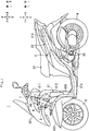
- FIG. 1 is a view of the leaning vehicle 1 viewed from the leaning-vehicle (1) left.
- the leaning-vehicle (1) frontward direction is referred to as frontward direction "F”.
- the leaning-vehicle (1) backward direction is referred to as backward direction "B”.
- the leaning-vehicle (1) leftward direction is referred to as leftward direction "L”.
- the leaning-vehicle (1) rightward direction is referred to as rightward direction “R”.
- the leaning-vehicle (1) upward direction is referred to as upward direction "U”.
- the leaning-vehicle (1) downward direction is referred to as downward direction "D”.
- the leaning-vehicle (1) front back direction is referred to as front back direction "FB”.
- the leaning-vehicle (1) left-right direction is referred to as left right direction "LR”.
- the leaning-vehicle (1) up-down direction is referred to as up down direction "UD”.
- the leaning-vehicle (1) frontward direction is a traveling direction of the leaning vehicle 1.
- the leaning-vehicle (1) backward direction is the opposite direction of the traveling direction of the leaning vehicle 1.
- the leaning-vehicle (1) leftward direction is a leftward direction based on a rider straddling the leaning vehicle 1.
- the leaning-vehicle (1) rightward direction is a rightward direction based on the rider straddling the leaning vehicle 1.
- the leaning-vehicle (1) upward direction is an upward direction based on the rider straddling the leaning vehicle 1.
- the leaning-vehicle (1) downward direction is a downward direction based on the rider straddling the leaning vehicle 1.
- a vehicle body frame 21 can lean in leftward direction “L” or rightward direction “R”.
- the vehicle-body-frame (21) up-down and left-right directions do not respectively coincide with the leaning-vehicle (1) up-down and left-right directions "UD” and "LR”.
- the vehicle-body-frame (21) up-down and left-right directions in an upright state respectively coincide with the leaning-vehicle (1) up-down and left-right directions "UD” and "LR”.
- the vehicle-body-frame (21) frontward direction is referred to as frontward direction "f”.
- the vehicle-body-frame (21) backward direction is referred to as backward direction "b".
- the vehicle-body-frame (21) leftward direction is referred to as leftward direction "l”.
- the vehicle-body-frame (21) rightward direction is referred to as rightward direction "r”.
- the vehicle-body-frame upward direction 21 is referred to as upward direction "u”.
- the vehicle-body-frame downward direction 21 is referred to as "d”.
- the vehicle-body-frame (21) front-back direction is referred to as front back direction "fb”.
- the vehicle-body-frame left-right direction 21 is referred to as left right direction "lr”.
- the vehicle-body-frame (21) up-down direction is referred to as up down direction "ud”.
- axes and members extending in the front back direction do not always indicate only axes and members parallel to the front back direction.
- the axes and the members extending in the front back direction mean axes and members leaning in a range of ⁇ 45° with respect to the front back direction.
- axes and members extending in the up down direction mean axes and members leaning in a range of ⁇ 45° with respect to the up down direction.
- Axes and members extending in the left right direction mean axes and members leaning in a range of ⁇ 45° with respect to the left right direction.
- the upright state of the vehicle body frame 21 means a state in which the front wheel is neither steered nor leaned in a state in which a rider does not ride the leaning vehicle 1 and fuel is not loaded in the leaning vehicle 1.
- a first member being supported by a second member includes the first member being attached (i.e., fixed) to the second member to be immovable with respect to the second member and the first member being attached to the second member to be movable with respect to the second member.
- the first member being supported by the second member includes both of the first member being directly attached to the second member and the first member being attached to the second member via a third member.
- the leaning vehicle 1 includes a leaning-vehicle main body section 2, a pair of left and right front wheels 3, a rear wheel 4, a link mechanism 5, and a steering mechanism 7.
- the leaning-vehicle main body section 2 includes a vehicle body frame 21, a vehicle body cover 22, a seat 24, and a power unit 25.
- the vehicle body frame 21 leans in the rightward direction "R” during a right turn.
- the vehicle body frame 21 leans in the leftward direction “L” during a left turn.
- the vehicle body frame 21 includes a head pipe 211, a down frame 212, an under frame 214, and a rear frame 215.
- a portion hidden by the vehicle body cover 22 is indicated by a broken line.
- the vehicle body frame 21 supports the seat 24, the power unit 25, and the like.
- the power unit 25 includes a driving source such as an engine or an electric motor and a transmission device.
- the head pipe 211 is disposed in a front part of the leaning vehicle 1.
- the front part of the leaning vehicle 1 is a portion located further in the frontward direction "F" than the front end of the seat 24 in the leaning vehicle 1.
- a rear part of the leaning vehicle 1 is a portion located further in the backward direction "B" than the front end of the seat 24 in the leaning vehicle 1.
- the head pipe 211 is disposed to lean with respect to the up down direction "ud” such that the upper end portion of the head pipe 211 is located further in the backward direction "b” than the lower end portion of the head pipe 211 when the vehicle body frame 21 is viewed from right "r" or left “l”.
- the steering mechanism 7 and the link mechanism 5 are disposed around the head pipe 211.
- a steering shaft 60 of the steering mechanism 7 is rotatably inserted into the head pipe 211.
- the link mechanism 5 is supported by the head pipe 211.
- the down frame 212 is disposed further in the backward direction "b" than the head pipe 211.
- the down frame 212 is formed in a cylindrical shape extending in the up down direction "ud".
- the upper end portion of the down frame 212 is located behind "b" the lower end portion of the head pipe 211.
- the upper end portion of the down frame 212 is fixed to the lower end portion of the head pipe 211 by a not-shown connecting section.
- the under frame 214 extends in the backward direction “b” and the upward direction “u” from the lower end portion of the down frame 212.
- the rear frame 215 extends in the backward direction “b” and the upward direction “u” from the rear end of the under frame 214.
- the vehicle body frame 21 is covered by the vehicle body cover 22.
- the vehicle body cover 22 includes a front cover 221, a pair of left and right front fenders 223, and a leg shield 225.
- the front cover 221 is located in front "f" of the seat 24.
- the front cover 221 covers at least parts of the steering mechanism 7 and the link mechanism 5.
- FIG. 2 is a view of the front part of the leaning vehicle 1 viewed from front "F”.
- FIG. 3 is a view of the front part of the leaning vehicle 1 viewed from above "U”.
- the vehicle body cover 22 is shown in a transparent state.
- the steering mechanism 7 includes a steering-force transmitting mechanism 6, a left buffering mechanism 33, a right buffering mechanism 34, and a pair of left and right front wheels 3.
- the pair of left and right front wheels 3 includes a left front wheel 31 (an example of a left steerable wheel) and a right front wheel 32 (an example of a right steerable wheel).
- the left front wheel 31 is disposed further in the leftward direction “l” than the center in the left right direction “lr” of the vehicle body frame 21.
- the right front wheel 32 is disposed further in the rightward direction “r” than the center in the left right direction “lr” of the vehicle body frame 21.
- the left front wheel 31 and the right front wheel 32 are disposed symmetrically with respect to the center in the left right direction "lr" of the vehicle body frame 21 in the upright state.
- a left front fender 227 is disposed above "u” the left front wheel 31.
- a right front fender 228 is disposed above "u” the right front wheel 32.
- the left front wheel 31 is supported by the left buffering mechanism 33.
- the right front wheel 32 is supported by the right buffering mechanism 34.
- the left buffering mechanism 33 includes a left lower section 33a, a left upper section 33b, and a left supporting section 33c.
- the left lower section 33a extends in the up down direction "ud".
- the left supporting section 33c is disposed at the lower end portion of the left lower section 33a.
- the left supporting section 33c rotatably supports the left front wheel 31.
- the left front wheel 31 can rotate around a left front wheel axle 314 (an example of a left steerable wheel axle).
- the left front wheel axle 314 extends in the leftward direction "l" from the left supporting section 33c.
- the left upper section 33b extends in the up down direction "ud”.
- the left upper section 33b is disposed above "u" the left lower section 33a in a state in which a lower end vicinity of the left upper section 33b is inserted into the left lower section 33a.
- the upper end portion of the left upper section 33b is fixed to a left bracket 317.
- the left buffering mechanism 33 is a buffering mechanism of a so-called telescopic type.
- the left upper section 33b relatively moves in an extending direction of the left lower section 33a with respect to the left lower section 33a, whereby the left buffering mechanism 33 can extend and contract in the direction. Consequently, the left buffering mechanism 33 buffers displacement in the up down direction "ud" of the front wheel 31 with respect to the left upper section 33b.
- the right buffering mechanism 34 includes a right lower section 34a, a right upper section 34b, and a right supporting section 34c.
- the right lower section 34a extends in the up down direction "ud".
- the right supporting section 34c is disposed at the lower end portion of the right lower section 34a.
- the right supporting section 34c rotatably supports the right front wheel 32.
- the right front wheel 32 can rotate around a right front wheel axle 324 (an example of a right steerable wheel axle).
- the right front wheel axle 324 extends in the rightward direction "r" from the right supporting section 34c.
- the right upper section 34b extends in the up down direction "ud”.
- the right upper section 34b is disposed above "u" the right lower section 34a in a state in which a lower end vicinity of the right upper section 34b is inserted into the right lower section 34a.
- the upper end portion of the right upper section 34b is fixed to a right bracket 327.
- the right buffering mechanism 34 is a buffering mechanism of a so-called telescopic type.
- the right upper section 34b relatively moves in an extending direction of the right lower section 34a with respect to the right lower section 34a, whereby the right buffering mechanism 34 can extend and contract in the direction. Consequently, the right buffering mechanism 34 buffers displacement in the up down direction "ud" of the front wheel 32 with respect to the right upper section 34b.
- the steering-force transmitting mechanism 6 is disposed further in the upward direction "u" than the left front wheel 31 and the right front wheel 32.
- the steering-force transmitting mechanism 6 includes a steering member 28, a tie rod 67, a left bracket 317, a right bracket 327, and a bracket 337.
- the steering member 28 is a member to which a steering force of the rider is input.
- the steering member 28 includes a steering shaft 60 and a handle 23.
- the handle 23 is coupled to an upper part of the steering shaft 60.
- the steering shaft 60 is rotatably supported by the vehicle body frame 21.
- the lower end portion of the steering shaft 60 is located further in the frontward direction "f' than the upper end portion of the steering shaft 60. A part of the steering shaft 60 is inserted into the head pipe 211.
- the steering shaft 60 extends in the up down direction "ud”. Consequently, the steering shaft 60 is capable of rotating around the center axis of the steering shaft 60 extending in the up down direction "ud".
- the steering shaft 60 is rotated according to operation of the handle 23 by the rider.
- the bracket 337 is fixed to the lower end portion of the steering shaft 60. Accordingly, the bracket 337 is capable of rotating around the center axis of the steering shaft 60 together with the steering shaft 60.
- the tie rod 67 transmits the rotation of the steering shaft 60 by the operation of the handle 23 to the left buffering mechanism 33 and the right buffering mechanism 34.
- the tie rod 67 extends in the left right direction "LR".
- the center in the left right direction of the tie rod 67 is supported by the bracket 337.
- the left end portion of the tie rod 67 is supported by the left bracket 317.
- the right end portion of the tie rod 67 is supported by the right bracket 327.
- the link mechanism 5 is explained with reference to FIG. 2 and FIG. 3 .
- the link mechanism 5 is a link mechanism of a parallelogram link type.
- the link mechanism 5 is disposed further in the downward direction "d" than the handle 23.
- the link mechanism 5 is supported by the head pipe 211 of the vehicle body frame 21.
- the link mechanism 5 includes an upper cross member 51, a lower cross member 52, a left side member 53, and a right side member 54.
- the upper cross member 51, the lower cross member 52, the left side member 53, and the right side member 54 are a plurality of link members that can be displaced with respect to the vehicle body frame 21.
- the displacement in this specification includes displacement by a translational movement, displacement by a rotational movement, and displacement by a combination of the translational movement and the rotational movement.
- the upper cross member 51 extends in the left right direction "LR".
- the upper cross member 51 is disposed in front "f" of the head pipe 211 and further in the upward direction "u” than the left front wheel 31 and the right front wheel 32.
- the upper cross member 51 is supported on the head pipe 211 by a supporting section C.
- the supporting section C is located in an intermediate part of the upper cross member 51 and an upper part of the head pipe 211.
- the left part of the upper cross member 51 is a portion located in the most left when the upper cross member 51 is equally divided into three in the left right direction "LR".
- the right part of the upper cross member 51 is a portion located in the most right when the upper cross member 51 is equally divided into three in the left right direction "LR".
- the intermediate part of the upper cross member 51 is a portion located in the middle when the upper cross member 51 is equally divided into three in the left right direction "LR".
- the upper part of the head pipe 211 is the upper half of the head pipe 211.
- the lower part of the head pipe 211 is the lower half of the head pipe 211.
- the supporting section C is a shaft extending in the front back direction "fb".
- the supporting section C extends from the head pipe 211 in the frontward direction "f' in a state in which the supporting section C slightly leans in the upward direction "u”.
- the upper cross member 51 is capable of rotating with respect to the head pipe 211 around the supporting section C.
- the lower cross member 52 includes a front lower cross member 522A and a rear lower cross member 522B.
- the front lower cross member 522A extends in the left right direction "LR".
- the front lower cross member 522A is disposed in front "f" of the head pipe 211 and further in the downward direction “d” than the upper cross member 51 and further in the upward direction “u” than the left front wheel 31 and the right front wheel 32.
- the front lower cross member 522A is supported on the head pipe 211 by a supporting section F.
- the supporting section F is located in an intermediate part of the front lower cross member 522A and a lower part of the head pipe 211.
- the left part of the front lower cross member 522A is a portion located in the most left when the front lower cross member 522A is equally divided into three in the left right direction "LR".
- the right part of the front lower cross member 522A is a portion located in the most right when the front lower cross member 522A is equally divided into three in the left right direction "LR”.
- the intermediate part of the front lower cross member 522A is a portion located in the middle when the front lower cross member 522A is equally divided into three in the left right direction "LR”.
- the supporting section F is a shaft extending in the front back direction "fb".
- the supporting section F extends from the head pipe 211 in the frontward direction "f” in a state in which the supporting section F lightly leans in the upward direction "u”.
- the front lower cross member 522A is capable of rotating with respect to the head pipe 211 around the supporting section F.
- the rear lower cross member 522B extends in the left right direction "LR".
- the rear lower cross member 522B is disposed behind "b" the head pipe 211 and further in the lower direction “d” than the upper cross member 51 and further in the upward direction “u” than the left front wheel 31 and the right front wheel 32.
- the rear lower cross member 522B is supported on the head pipe 211 by the supporting section F.
- the supporting section F is located in an intermediate part of the rear lower cross member 522B and a lower part of the head pipe 211.
- the left part of the rear lower cross member 522B is a portion located in the left when the rear lower cross member 522B is equally divided into three in the left right direction "LR".
- the right part of the rear lower cross member 522B is a portion located in the most right when the rear lower cross member 522B is equally divided into three in the left right direction "LR".
- the intermediate part of the rear lower cross member 522B is a portion located in the middle when the rear lower cross member 522B is equally divided into three in the left right direction "LR”.
- the supporting section F is a shaft extending in the front back direction "fb" as explained above. However, the supporting section F extends from the head pipe 211 in the backward direction "b" in a state in which the supporting section F slightly leans in the downward direction "d".
- the rear lower cross member 522B is capable of rotating with respect to the head pipe 211 around the supporting section F.
- the left side member 53 extends in the up down direction "ud”. Therefore, the extending direction of the left side member 53 is parallel to the extending direction of the head pipe 211.
- the left side member 53 is disposed to the left “l” of the head pipe 211.
- the left side member 53 is disposed above "u" the left front wheel 31 and further in the upward direction "u” than the left buffering mechanism 33.
- the left side member 53 is supported on the upper cross member 51 by a supporting section D.
- the supporting section D is located in an upper part of the left side member 53 and a left part of the upper cross member 51.
- the upper part of the left side member 53 is the upper half of the left side member 53.
- the lower part of the left side member 53 is the lower half of the left side member 53.
- the supporting section D is a shaft extending in the front back direction "fb".
- the left side member 53 is capable of rotating with respect to the upper cross member 51 around the supporting section D.
- the left side member 53 is supported on the front lower cross member 522A and the rear lower cross member 522B by a supporting section G.
- the supporting section G is located in a lower part of the left side member 53, a left part of the front lower cross member 522A, and a left part of the rear lower cross member 522B.
- the supporting section G is a shaft extending in the front back direction "fb".
- the left side member 53 is capable of rotating with respect to the front lower cross member 522A and the rear lower cross member 522B around the supporting section G.
- the left bracket 317 is supported at the lower end portion of the left side member 53.
- the left bracket 317 is capable of rotating with respect to the left side member 53 around a left center axis Y1.
- the left center axis Y1 is a center axis of the left side member 53. Therefore, the left center axis Y1 extends in the up down direction "ud".
- the right side member 54 extends in the up down direction "ud”. Therefore, the extending direction of the right side member 54 is parallel to the extending direction of the head pipe 211.
- the right side member 54 is disposed to the right “r” of the head pipe 211.
- the right side member 54 is disposed above "u” the right front wheel 32 and further in the upward direction "u” than the right buffering mechanism 34.
- the right side member 54 is supported on the upper cross member 51 by a supporting section E.
- the supporting section E is located in an upper part of the right side member 54 and a right part of the upper cross member 51.
- the upper part of the right side member 54 is the upper half of the right side member 54.
- the lower part of the right side member 54 is the lower half of the right side member 54.
- the supporting section E is a shaft extending in the front back direction "fb".
- the right side member 54 is capable of rotating with respect to the upper cross member 51 around the supporting section E.
- the right side member 54 is supported on the front lower cross member 522A and the rear lower cross member 522B by a supporting section H.
- the supporting section H is located in a lower part of the right side member 54, a right part of the front lower cross member 522A, and a right part of the rear lower cross member 522B.
- the supporting section H is a shaft extending in the front back direction "fb".
- the right side member 54 is capable of rotating with respect to the front lower cross member 522A and the rear lower cross member 522B around the supporting section H.
- the right bracket 327 is supported at the lower end portion of the right side member 54.
- the right bracket 327 is capable of rotating with respect to the right side member 54 around a right center axis Y2.
- the right center axis Y2 is the center axis of the right side member 54. Therefore, the right center axis Y2 extends in the up down direction "ud".
- the upper cross member 51, the lower cross member 52, the left side member 53, and the right side member 54 are coupled such that the upper cross member 51 and the lower cross member 52 keep postures parallel to each other and the left side member 53 and the right side member 54 keep postures parallel to each other.
- the link mechanism 5 includes the left buffering mechanism 33.
- the left buffering mechanism 33 is disposed below “d” the left side member 53.
- the left buffering mechanism 33 is supported by the left bracket 317. Specifically, the upper end portion of the left buffering mechanism 33 is fixed to the left bracket 317. Further, the left buffering mechanism 33 supports the left front wheel 31. Therefore, the left side member 53 supports the left front wheel 31 via the left bracket 317 and the left buffering mechanism 33. That is, the link mechanism 5 supports the left front wheel 31.
- Such a left buffering mechanisms 33 leans in the left right direction "LR" together with the left side member 53.
- the link mechanism 5 includes the right buffering mechanism 34.
- the right buffering mechanism 34 is disposed below “d” the right side member 54.
- the right buffering mechanism 34 is supported by the right bracket 327. Specifically, the upper end of the right buffering mechanism 34 is fixed to the right bracket 327. Further, the right buffering mechanism 34 supports the right front wheel 32. Therefore, the right side member 54 supports the right front wheel 32 via the right bracket 327 and the right buffering mechanism 34. That is, the link mechanism 5 supports the right front wheel 32.
- Such a right buffering mechanism 34 leans in the left right direction "LR" together with the right side member 54.
- FIG. 4 is a view of the front part of the leaning vehicle 1 in a left-steered state viewed from above "U”.
- the steering shaft 60 rotates counterclockwise when the leaning vehicle 1 is viewed from above "U". Since the bracket 337 is fixed to the lower end of the steering shaft 60, the bracket 337 rotates counterclockwise together with the steering shaft 60 when the leaning vehicle 1 is viewed from above "U”.
- the tie rod 67 translates in the leftward direction “L” and the backward direction “B” according to the rotation of the bracket 337.
- the left end portion of the tie rod 67 is supported by the front end portion of the left bracket 317.
- the left bracket 317 is capable of rotating around the left center axis Y1 (see FIG. 2 ). Therefore, according to the translational movement of the tie rod 67, the left bracket 317 rotates counterclockwise when the leaning vehicle 1 is viewed from above "U”.
- the right end portion of the tie rod 67 is supported by the front end portion of the right bracket 327.
- the right bracket 327 is capable of rotating around the right center axis Y2 (see FIG. 2 ). Therefore, according to the translational movement of the tie rod 67, the right bracket 327 rotates counterclockwise when the leaning vehicle 1 is viewed from above "U”.
- the left front wheel 31 is connected to the left bracket 317 via the left buffering mechanism 33. Therefore, according to the rotation of the left bracket 317, the left front wheel 31 rotates counterclockwise around the left center axis Y1 (see FIG. 2 ) when the leaning vehicle 1 is viewed from above "U".
- the right front wheel 32 is connected to the right bracket 327 via the right buffering mechanism 34. Therefore, according to the rotation of the right bracket 327, the right front wheel 32 rotates counterclockwise around the right center axis Y2 (see FIG. 2 ) when the leaning vehicle 1 is viewed from above "U".
- FIG. 5 is a view of the front part of the leaning vehicle 1, which is viewed from front "F”, in a leaned state to the left "L" of the vehicle body frame 21.
- the upper cross member 51, the lower cross member 52, the left side member 53, and the right side member 54 and the vehicle body frame 21 are relatively displaced such that the left front wheel axle 314 is located further in the upward direction "u” than the right front wheel axle 324, whereby the link mechanism 5 leans the vehicle body frame 21 to the left “L” during a left turn.
- the upper cross member 51, the lower cross member 52, the left side member 53, and the right side member 54 and the vehicle body frame 21 are relatively displaced such that the right front wheel axle 324 is located further in the upward direction "u” than the left front wheel axle 314, whereby the link mechanism 5 leans the vehicle body frame 21 to the rightward direction "R” during a right turn.
- the vehicle body frame 21 leans in leftward direction "L”.
- the shape of the link mechanism 5 changes, whereby the vehicle body frame 21 in the upright state leans in leftward direction "L".
- the upper cross member 51, the lower cross member 52, the left side member 53, and the right side member 54 are formed in rectangular shapes.
- the upper cross member 51, the lower cross member 52, the left side member 53, and the right side member 54 are formed in parallelogram shapes.
- the head pipe 211 leans in leftward direction "L".
- the upper cross member 51 rotates counterclockwise with respect to the head pipe 211 around the supporting section C when the leaning vehicle 1 is viewed from front "F”.
- the lower cross member 52 rotates counterclockwise with respect to the head pipe 211 around the supporting section F when the leaning vehicle 1 is viewed from front "F”. Consequently, the upper cross member 51 moves in the leftward direction "L” with respect to the lower cross member 52 when the leaning vehicle 1 is viewed from front "F”.
- the left side member 53 rotates clockwise with respect to the upper cross member 51 around the supporting section D when the leaning vehicle 1 is viewed from front "F".
- the right side member 54 rotates clockwise with respect to the upper cross member 51 around the supporting section E when the leaning vehicle 1 is viewed from front "F”.
- the left side member 53 rotates clockwise with respect to the lower cross member 52 around the supporting section G when the leaning vehicle 1 is viewed from front "F”.
- the right side member 54 rotates clockwise with respect to the lower cross member 52 around the supporting section H when the leaning vehicle 1 is viewed from front "F”. Consequently the left side member 53 and the right side member 54 lean in leftward direction "L" while keeping a state parallel to the head pipe 211.
- the left bracket 317 is supported by the lower end portion of the left side member 53. Therefore, the left bracket 317 leans in leftward direction “L” according to the leaning to the left “L” of the left side member 53. Since the left buffering mechanism 33 is supported by the left bracket 317, the left buffering mechanism 33 leans in leftward direction “L” according to the leaning to the left "L” of the left bracket 317. Since the left front wheel 31 is supported by the lower end portion of the left buffering mechanism 33, the left front wheel 31 leans in leftward direction “L” according to the leaning to the left "L” of the left buffering mechanism 33.
- the right bracket 327 is supported by the lower end portion of the right side member 54. Therefore, the right bracket 327 leans in leftward direction “L” according to the leaning to the left “L” of the right side member 54. Since the right buffering mechanism 34 is supported by the right bracket 327, the right buffering mechanism 34 leans in leftward direction “L” according to the leaning to the left "L” of the right bracket 327. Since the right front wheel 32 is supported by the lower end portion of the right buffering mechanism 34, the right front wheel 32 leans in leftward direction “L” according to the leaning to the left "L” of the right buffering mechanism 34.
- FIG. 6 is a view of the front part of the leaning vehicle 1 viewed from front "F".
- the leaning vehicle 1 includes the resistance-force changing mechanism 8.
- the resistance-force changing mechanism 8 is configured to be capable of changing a resistance force applied to a motion in which the vehicle body frame 21 and the plurality of link members (the upper cross member 51, the lower cross member 52, the left side member 53, and the right side member 54) are relatively displaced.
- the resistance-force changing mechanism 8 can switch a locked state in which the vehicle body frame 21 and the plurality of link members cannot be relatively displaced and an unlocked state in which the vehicle body frame 21 and the plurality of link members can be relatively displaced. In the locked state, a relatively large resistance force is applied to the motion in which the vehicle body frame 21 and the plurality of link members are relatively displaced.
- the resistance-force changing mechanism 8 is provided in front "f" of the link mechanism 5.
- the resistance-force changing mechanism 8 includes a supporting frame 81, a plate 82, a caliper 83, a restricting section 84, a transmitting mechanism 85, and an electric motor 86.
- the supporting frame 81 is fixed to the lower cross member 52. Therefore, the supporting frame 81 is capable of rotating around the supporting section F together with the lower cross member 52. Consequently, the supporting frame 81 can be displaced with respect to the head pipe 211.
- the vehicle body frame 21 includes a front frame 213 indicated by a broken line.
- the front frame 213 is disposed in front "f" of the link mechanism 5.
- the caliper 83 is fixed to the front frame 213. Consequently, the caliper 83 cannot be displaced with respect to the head pipe 211.
- the caliper 83 (an example of a first frictional-member driving mechanism) includes pads 831A and 831B (an example of a first frictional member).
- the pads 831A and 831B are disposed in this order from front "f' to back "b".
- the pads 831A and 831B are made of a high-friction material.
- the pads 831A and 831B are displaceable in the front back direction "fb" such that an interval between the pads 831A and 831B changes.
- the plate 82 (an example of a second frictional member) is disposed to be located between the pads 831A and 831B.
- the plate 82 linearly extends in the left right direction "lr".
- the electric motor 86 is fixed to the caliper 83.
- the electric motor 86 receives supply of electric power to thereby generate a driving force for changing the interval between the pads 831A and 831B.
- a rider operates a not-shown switch provided in the handle 23, whereby the electric motor 86 operates. Consequently, the interval between the pads 831A and 831B changes.
- the pad 831A comes into contact with the front surface of the plate 82 and the pad 831B comes into contact with the rear surface of the plate 82.
- the caliper 83 holds the plate 82.
- a state in which the caliper 83 holds the plate 82 is the locked state.
- the pad 831A does not come into contact with the front surface of the plate 82 and the pad 831B does not come into contact with the rear surface of the plate 82.
- the caliper 83 does not hold the plate 82.
- a state in which the caliper 83 does not hold the plate 82 is the unlocked state.
- the restricting section 84 and the transmitting mechanism 85 relatively displace the plate 82 and the caliper 83.
- the restricting section 84 includes a first restricting section 841, a second restricting section 842, and a third restricting section 843.
- the first restricting section 841, the second restricting section 842, and the third restricting section 843 are supported by the front frame 213 via a not-shown supporting structure.
- the first restricting section 841 and the second restricting section 842 are disposed further in the rightward direction "r" than the head pipe 211.
- the first restricting section 841 is disposed in a position where the first restricting section 841 can be in contact with the upper edge of the plate 82.
- the second restricting section 842 is disposed in a position where the second restricting section 842 can be in contact with the lower edge of the plate 82.
- the third restricting section 843 is disposed further in the leftward direction "l" than the head pipe 211.
- the third restricting section 843 is disposed in a position where the third restricting section 843 can be in contact with the upper edge of the plate 82. Accordingly, the restricting section 84 restricts displacement of the plate 82 to the up down direction "ud" in three places.
- the transmitting mechanism 85 is a member extending in the left right direction "lr". However, when the transmitting mechanism 85 is viewed from front "f', the transmitting mechanism 85 is formed in an L shape bent in the upward direction "u" in a right end portion vicinity of the transmitting mechanism 85.
- the transmitting mechanism 85 is supported on the supporting frame 81 by an upstream-side coupling section 851.
- the upstream-side coupling section 851 is located at the right end portion of the transmitting mechanism 85 and the upper end portion of the supporting frame 81.
- the upstream-side coupling section 851 is a shaft extending in the front back direction "fb".
- the transmitting mechanism 85 is capable of rotating with respect to the supporting frame 81 around the upstream-side coupling section 851.
- the transmitting mechanism 85 is supported on the plate 82 by a downstream-side coupling section 852.
- the downstream-side coupling section 852 is located at the upper left end portion of the transmitting mechanism 85 and the left end portion of the plate 82.
- the downstream-side coupling section 852 is a shaft extending in the front back direction "fb".
- the transmitting mechanism 85 is capable of rotating with respect to the plate 82 around the downstream-side coupling section 852.
- FIG. 7 is a view of the resistance-force changing mechanism 8, which is viewed from front "F”, in a leaned state in the leftward direction “L” of the vehicle body frame 21.
- FIG. 8 is a view of the resistance-force changing mechanism 8, which is viewed from front "F”, in a leaned state in the rightward direction "R” of the vehicle body frame 21.
- the plate 82 is supported by the restricting section 84. Therefore, when the restricting section 84 rotates clockwise when the leaning vehicle 1 is viewed from front "F", the plate 82 also rotates clockwise around the downstream-side coupling section 852. Further, when the caliper 83 and the restricting section 84 move in the leftward direction "L” and the downward direction “D", the plate 82 receives forces in the leftward direction "L” from the caliper 83 and the restricting section 84. Therefore, the transmitting mechanism 85 receives a force in the leftward direction "L” from the plate 82 in the downstream-side coupling section 852.
- the downstream-side coupling section 852 is located further in the upward direction "u" than the upstream-side coupling section 851.
- the transmitting mechanism 85 receives, from the plate 82, a rotational moment that rotates clockwise around the upstream-side coupling section 851 when the leaning vehicle 1 is viewed from front "F". Consequently, the transmitting mechanism 85 rotates clockwise around the upstream-side coupling section 851 when the leaning vehicle 1 is viewed from front "F". According to the operation explained above, the caliper 83 and the restricting section 84 can smoothly move in the leftward direction "l" along the plate 82.
- the plate 82 is supported by the restricting section 84. Therefore, when the restricting section 84 rotates counterclockwise when the leaning vehicle 1 is viewed from front "F", the plate 82 also rotates counterclockwise around the downstream-side coupling section 852. Further, when the caliper 83 and the restricting section 84 move in the right ward direction "R” and the downward direction “D", the plate 82 receives forces in the rightward direction "R” from the caliper 83 and the restricting section 84. Therefore, the transmitting mechanism 85 receives a force in the rightward direction "R” from the plate 82 in the downstream-side coupling section 852.
- the downstream-side coupling section 852 is located further in the upward direction "u" than the upstream-side coupling section 851.
- the transmitting mechanism 85 receives, from the plate 82, a rotational moment that rotates counterclockwise around the upstream-side coupling section 851. Consequently, when the leaning vehicle 1 is viewed from front "F", the transmitting mechanism 85 rotates counterclockwise around the upstream-side coupling section 851. According to the operation explained above, the caliper 83 and the restricting section 84 can smoothly move in the rightward direction "r" along the plate 82.
- the resistance-force changing mechanism 8 is configured such that the plate 82 and the pads 831A and 831B of the caliper 83 are relatively displaced in association with the relative displacement of the vehicle body frame 21 and the plurality of link members (the upper cross member 51, the lower cross member 52, the left side member 53, and the right side member 54).
- the pads 831A and 831B respectively come into contact with the front surface and the rear surface of the plate 82. Consequently, a frictional force is generated between the plate 82 and the pads 831A and 831B.
- the resistance force applied to the motion in which the plate 82 and the caliper 83 are relatively displaced increases.
- the plate 82 is supported by the lower cross member 52 via the supporting frame 81 and the transmitting mechanism 85.
- the caliper 83 is supported by the head pipe 211.
- a resistance force applied to a motion in which the lower cross member 52 rotates with respect to the head pipe 211 increases. That is, a resistance for applied to a motion in which the upper cross member 51, the lower cross member 52, the left side member 53, and the right side member 54 and the vehicle body frame 21 are relatively displaced increases.
- the resistance-force changing mechanism 8 is configured to change a contact state of the pads 831A and 831B and the plate 82 to thereby change a resistance force applied to a motion in which the vehicle body frame 21 and the plurality of link members (the upper cross member 51, the lower cross member 52, the left side member 53, and the right side member 54) are relatively displaced.
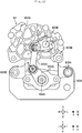
- FIG. 9 is an exterior perspective view of the caliper 83 and the electric motor 86.
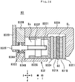
- FIG. 10 is a sectional view in X1-X1 of the caliper 83 shown in FIG. 9 .
- FIG. 10 a sectional view of the caliper 83 in the unlocked state is shown.
- the sectional view of FIG. 10 is schematically shown. Therefore, dimensions of FIG. 10 do not strictly coincide with dimensions of FIG. 9 .
- FIG. 11 is a functional block diagram of the caliper 83 and the electric motor 86.
- FIG. 12 is a view of the caliper 83 in the unlocked state viewed from front "f".
- the caliper 83 is a caliper of a so-called float type.
- the caliper 83 includes, as shown in FIG. 9 , a rear caliper body 833A and a front caliper body 833B.
- the electric motor 86 is fixed to the rear surface of the rear caliper body 833A.
- the front caliper body 833B covers the front surface of the rear caliper body 833A.
- a slit SL and a through-hole Sp are provided in the rear caliper body 833A.
- the slit SL traverses a block-like rear caliper body 833A in the left right direction "lr". Consequently, as shown in FIG. 9 , the slit SL connects the right surface and the left surface of the rear caliper body 833A.
- FIG. 9 it can be visually recognized that the slit SL is formed on the left surface of the rear caliper body 833A and it cannot be visually recognized that the slit SL is formed on the right surface of the rear caliper body 833A.
- the slit SL is opened on the lower surface of the rear caliper body 833A.
- the plate 82 (not shown in FIG. 9 ) traverses the slit SL in the left right direction "lr”. Therefore, the plate 82 extends from the slit SL in the leftward direction "l” and the rightward direction "r”.
- the through-hole Sp extends from the front surface of the rear caliper body 833A toward the backward direction "b”.
- the through-hole Sp is connected to the slit SL.
- the through-hole Sp is formed in a circular shape when the caliper 83 is viewed from front "f".
- the caliper 83 includes, as shown in FIG. 11 , the pads 831A and 831B and a driving-force transmitting mechanism 832.
- the driving-force transmitting mechanism 832 includes, as shown in FIG. 11 , a gear group 832A, arms 832B, 832C, and 832D, a bolt 832E, a nut 832F, a piston 832G, and shims 832H and 8321.
- the driving-force transmitting mechanism 832 includes a rigid member for transmitting a driving force generated by the electric motor 86 to the pads 831A and 831B.
- the rigid member is a member not elastically deformed during the motion of the caliper 83.
- the member not elastically deformed is a member designed without considering a shape change due to elastic deformation during the motion of the caliper 83. Therefore, a member such as a wire used on the premise of elastic deformation during the motion of the caliper 83 is not included in the rigid member in this specification.
- the gear group 832A is a plurality of gears housed in upper right parts of the rear caliper body 833A and the front caliper body 833B.
- the gear group 832A cannot be visually recognized because the gear group 832A is covered by the rear caliper body 833A and the front caliper body 833B.
- a reference sign and a leader line are added to a position where the gear group 832A is provided.
- the gear group 832A is a reduction gear. Therefore, the gear group 832A reduces and outputs rotating speed of the electric motor 86 and increases and outputs torque of the electric motor 86.
- a gear disposed on a most upstream side in the gear group 832A is fixed to a rotating shaft Ax (not shown in the figure) of the electric motor 86. Therefore, the gear disposed on the most upstream side in the gear group 832A rotates together with the rotating shaft Ax around the rotating shaft Ax (not shown in the figure).
- a gear disposed on a most downstream side in the gear group 832A is fixed to a supporting section I.
- the supporting section I is a shaft extending in the front back direction "fb".
- the supporting section I pierces through the front caliper body 833B in the front back direction "fb".
- the gear disposed on the most downstream side in the gear group 832A rotates together with the supporting section I around the supporting section I.
- the arm 832B is a bar-like member.
- the arm 832B is disposed in front "f" of the front caliper body 833B.
- the arm 832B is fixed to the supporting section I. Consequently, the arm 832B is capable of rotating together with the supporting section I around the supporting section I. That is, when the electric motor 86 is driven and the rotating shaft Ax rotates, the gear group 832A rotates and the arm 832B rotates together with the supporting section I.
- the bolt 832E includes, as shown in FIG. 10 , a shaft section 8321 and an expanded diameter section 8322.
- the shaft section 8321 is a shaft extending in the front back direction "fb".
- the shaft section 8321 pierces through the front caliper body 833B in the front back direction "fb”.
- the shaft section 8321 coincides with the center axis of the through-hole Sp.
- a male screw is formed in a front part of the shaft section 8321.
- the front part of the shaft section 8321 is the front half of the shaft section 8321.
- a rear part of the shaft section 8321 is the rear half of the shaft section 8321.
- the expanded diameter section 8322 has a diameter larger than the diameter of the shaft section 8321.
- the expanded diameter section 8322 is provided in the rear part of the shaft section 8321.
- the shaft section 8321 is supported by bearings 834A and 834B, whereby such a bolt 832E is capable of rotating with respect to the rear caliper body 833A and the front caliper body 833B.
- the bearing 834A is adjacent to the expanded diameter section 8322 in the frontward direction "f" of the expanded diameter section 8322.
- the bearing 834B is adjacent to the expanded diameter section 8322 in the backward direction "b" of the expanded diameter section 8322.
- the bearings 834A and 834B are fixed to the front caliper body 833B. Consequently, the bolt 832E cannot move in the front back direction "fb" with respect to the front caliper body 833B.
- the arm 832D is a bar-like member.
- the arm 832D is disposed in front "f' of the front caliper body 833B.
- the arm 832D is fixed to the front end portion of the shaft section 8321 of the bolt 832E. Consequently, the arm 832B is capable of rotating with respect to the rear caliper body 833A and the front caliper body 833B together with the bolt 832E around the shaft section 8321.
- the arm 832C is a bar-like member including a first end portion and a second end portion.
- the first end portion is an upper end portion of the two end portions of the arm 832C.
- the second end portion is a lower end portion of the two end portions of the arm 832C.
- the arm 832C is disposed in front "f" of the front caliper body 833B.
- the arm 832C is supported on the arm 832B by a supporting section J.
- the supporting section J is located at the first end portion of the arm 832C and the distal end portion of the arm 832B.
- the distal end portion of the arm 832B is an end portion farther from the supporting section I of the two end portions of the arm 832B.
- the supporting section J is a shaft extending in the front back direction "fb".
- the arm 832C is capable of rotating with respect to the arm 832B around the supporting section J.
- the arm 832C is supported on the arm 832D by a supporting section K.
- the second end portion of the arm 832C is supported by the distal end portion of the arm 832D.
- the supporting section K is located at the second end portion of the arm 832C and the distal end portion of the arm 832D.
- the distal end portion of the arm 832D is an end portion farther from the supporting section E of the two end portions of the arm 832D.
- the supporting section K is a shaft extending in the front back direction "fb".
- the arm 832C is capable of rotating with respect to the arm 832D around the supporting section K.
- the piston 832G is a cylinder member having a center axis extending in the front back direction "fb".
- the piston 832G includes a rear part that closes an opening locating at rear potion of the cylinder.
- the piston 832G does not include a front surface that closes an opening locating at front portion of the cylinder.
- the piston 832G is disposed in the through-hole Sp.
- the piston 832G is movable in the front back direction "fb" in the through-hole Sp.
- the nut 832F is disposed in the piston 832G.
- the nut 832F is fixed to the piston 832G. Accordingly, the nut 832F is capable of moving in the front back direction "fb" in the through-hole Sp together with the piston 832G.
- the nut 832F is attached to the male screw formed in the shaft section 8321 of the bolt 832E. Consequently, when the bolt 832E rotates counterclockwise when the caliper 83 is viewed from front "f', the nut 832F moves in the backward direction "b" with respect to the bolt 832E.
- the piston 832G also moves in the backward direction “b” with respect to the bolt 832E according to the movement in the backward direction "b” of the nut 832F.
- the bolt 832E rotates clockwise when the caliper 83 is viewed from front "f'
- the nut 832F moves in the frontward direction “f' with respect to the bolt 832E.
- the piston 832G also moves in the frontward direction “f” with respect to the bolt 832E according to the movement in the frontward direction "f' of the nut 832F.
- the shim 832H is fixed to the rear surface of the piston 832G.
- the pad 831A is fixed to the rear surface of the shim 832H. Consequently, the pad 831A is opposed to the front surface of the plate 82.
- the shim 831I is fixed to a surface opposed to the rear surface of the plate 82.
- the pad 831B is fixed to the front surface of the shim 8321. Consequently, the pad 831B is opposed to the rear surface of the plate 82.
- the caliper 83 includes, as shown in FIG. 12 , a caliper base 835 and slide pins 836A and 836B. As shown in FIG. 9 , the caliper base 835 is a tabular member. As shown in FIG. 6 , the caliper base 835 is fixed to the front frame 213. The rear caliper body 833A is supported on the caliper base 835 by the slide pins 836A and 836B. The rear caliper body 833A is capable of moving in the front back direction "fb" with respect to the caliper base 835 along the slide pins 836A and 836B.
- the electric motor 86 is fixed to the rear caliper body 833A. Therefore, the electric motor 86 is integrated with the caliper 83 and cannot be displaced with respect to the caliper 83. Further, the rear caliper body 833A is supported by the caliper base 835. The caliper base 835 is fixed to the front frame 213 (not shown in the figure). Therefore, the caliper 83 and the electric motor 86 are supported by the front frame 213 (not shown in the figure) via the caliper base 835.
- a position where the caliper 83 is supported in the front frame 213 (i.e., the vehicle body frame 21) and a position where the electric motor 86 is supported in the front frame 213 (i.e., the vehicle body frame 21) are the same.
- the caliper 83 and the electric motor 86 are supported by the front frame 213 via the same member (the caliper base 835).
- FIG. 13 is a view of the caliper 83 in the locked state viewed from front "f".
- FIG. 14 is a sectional view in X1-X1 of the caliper 83 shown in FIG. 9 .
- a sectional view of the caliper 83 in the locked state is shown.
- the arm 832D is located further in the downstream side "d" than the distal end of the arm 832B shown in FIG. 12 .
- the distal end portion of the arm 832B and the distal end portion of the arm 832D are coupled via the arm 832C. Therefore, the distal end portion of the arm 832D receives a force from the arm 832B toward the downward direction "d" via the arm 832C.
- the distal end portion of the arm 832D is located further in the leftward direction "l” than the bolt 832E. Consequently, when the caliper 83 is viewed from front "f', the arm 832D receives, from the arm 832C, a rotational moment that rotates counterclockwise around the bolt 832E. As a result, when the caliper 83 is viewed from front "f", the arm 832D is rotated counterclockwise.
- the front caliper body 833B and the rear caliper body 833A move in the frontward direction "f' with respect to the caliper base 835.
- the pad 831B comes into contact with the rear surface of the plate 82.
- the caliper 83 changes from the unlocked state to the locked state.
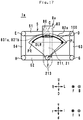
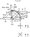
- FIG. 15 and FIG. 16 are diagrams showing a positional relation between a movable region A1 of the upper cross member 51, the lower cross member 52, the left side member 53, and the right side member 54 and the electric motor 86.
- FIG. 15 is a view of the movable region A1 and the electric motor 86 viewed from front "f".
- FIG. 16 is a view of the movable region A1 and the electric motor 86 viewed from left "l”.
- a state in which the left front wheel 31 is located in the uppermost end "u” in a movable region of the left front wheel 31 (not shown in the figure) and the right front wheel 32 is located in the lowermost end “d” in a movable region of the right front wheel 32 (not shown in the figure) as shown in FIG. 7 is referred to as maximum left leaning state.
- a state in which the left front wheel 31 is located in the lowermost end "d” in the movable region of the left front wheel 31 and the right front wheel 32 is located in the uppermost end "u” in the movable region of the right front wheel 32 as shown in FIG. 8 is referred to as maximum right leaning state.
- the movable region A1 is a region where the upper cross member 51, the lower cross member 52, the left side member 53, and the right side member 54 pass when the link mechanism 5 changes from the maximum left leaning state to the maximum right leaning state (or when the link mechanism 5 changes from the maximum right leaning state to the maximum left leaning state).
- the movable region A1 when the movable region A1 is viewed from front "f", the movable region A1 is formed in a rectangular shape, the center of the upper side of which recesses in the downward direction “d” and the center of the lower side of which recesses in the upward direction “u”.
- the movable region A1 when the movable region A1 is viewed from left “l”, the movable region A1 is formed in a parallelogram shape.
- the upper cross member 51 rotates around the supporting section C.
- the supporting section C slightly leans in the upward direction "u” with respect to the front back direction "fb”. Therefore, a movable region of the upper cross member 51 slightly leans in the backward direction "b” with respect to the up down direction "ud”.
- a position where the pads 831A and 831B are opposed on the plate 82 is defined as a left leaning end portion position PL.
- a position where the pads 831A and 831B are opposed on the plate 82 is defined as a right leaning end portion position PR.
- the link mechanism 5 When the link mechanism 5 is viewed from front "f", the position of the center of gravity of the pad 831A in the maximum right leaning state shown in FIG. 8 is defined as the right leaning end portion position PR. Further, the distance between the left leaning end portion position PL and the right leaning end portion position PR is defined as a distance DLR.
- the electric motor 86 is disposed near the movable region A1. Specifically, as shown in FIG. 15 and FIG. 16 , a region, a distance to which from the movable region A1 is the distance DLR or less, is defined as a motor disposition region A2. As shown in FIG. 16 , when the motor disposition region A2 is viewed from left “l", the motor disposition region A2 is formed in a rectangular shape cut off near a corner located in the backward direction "b" and the upward direction "u". In the vehicle body frame 21 in the upright state, the entire electric motor 86 is located in the motor disposition region A2.
- the electric motor 86 does not include an electric wire drawn out from a housing of the electric motor 86 to a housing outside and connected to components (e.g., a control board and a battery) other than the electric motor 86. Therefore, such an electric wire may be disposed outside the movable region A1.
- the rotating shaft Ax of the electric motor 86 extends in the front back direction "fb" as shown in FIG. 16 .
- the rotating shaft Ax extending in the front back direction “fb” means that the rotating shaft Ax is parallel to the front back direction "fb” and the rotating shaft Ax slightly leans in the up down direction "ud” with respect to the front back direction "fb".
- the rotating shaft Ax may lean within a range of 10° in the up down direction "ud” with respect to the front back direction "fb".
- the resistance-force changing mechanism 8 includes the plate 82, the caliper 83, and the electric motor 86.
- the caliper 83 includes the pads 831A and 831B.
- the resistance-force changing mechanism 8 is configured such that the plate 82 and the pads 831A and 831B are relatively displaced in association with the relative displacement of the vehicle body frame 21 and the plurality of link members (the upper cross member 51, the lower cross member 52, the left side member 53, and the right side member 54).
- the resistance-force changing mechanism 8 operates the electric motor 86 to change a contact state of the pads 831A and 831B and the plate 82.
- the resistance-force changing mechanism 8 changes a resistance force applied to the motion in which the vehicle body frame 21 and the plurality of link members are relatively displaced.
- the pads 831A and 831B and the plate 82 are disposed near the link mechanism 5 to be capable of interlocking to the operation of the plurality of link members.
- the plate 82 moves with respect to the plurality of link members according to the operation of the link mechanism 5.
- a moving distance of the plate 82 with respect to the plurality of link members is the distance DLR between the left leaning end portion position PL and the right leaning end portion position PR.
- the motor disposition region A2 is a region away from the movable region A1 of the plurality of link members by the distance equal to or smaller than the distance DLR between the left leaning end portion position PL and the right leaning end portion position PR. Therefore, in the vehicle body frame 21 in the upright state, the electric motor 86 is disposed in the motor disposition region A2. Consequently, the distance from the electric motor 86 to the pads 831A and 831B decreases. The transmission path of the driving force from the electric motor 86 to the pads 831A and 831B also decreases.
- the caliper 83 and the electric motor 86 are supported by the front frame 213.
- the caliper 83 and the electric motor 86 are close. Consequently, a position where the caliper 83 is supported by the front frame 213 and a position where the electric motor 86 is supported by the front frame 213 can be set the same. Accordingly, a mechanism for supporting the caliper 83 and the electric motor 86 with the front frame 213 is simplified. As a result, it is possible realize a reduction in the size of the front part of the leaning vehicle 1.
- a probability of presence of a structure between the pads 831A and 831B and the electric motor 86 decreases. Accordingly, it is less necessary to complexly bend the transmission path of the driving force from the electric motor 86 to the pads 831A and 831B to avoid the structure present between the pads 831A and 831B and the electric motor 86. Accordingly, rather than a wire having flexibility, a plurality of rigid members can be use in the driving-force transmitting mechanism 832 that transmits the driving force generated by the electric motor 86 to the pads 831A and 831B.
- the driving-force transmitting mechanism 832 includes the gear group 832A, which is the plurality of rigid members, the arms 832B, 832C, and 832D, the bolt 832E, the nut 832F, the piston 832G, and the shims 832H and 8321.
- the gear group 832A which is the plurality of rigid members, the arms 832B, 832C, and 832D, the bolt 832E, the nut 832F, the piston 832G, and the shims 832H and 8321.
- the gear group 832A which is the plurality of rigid members
- the arms 832B, 832C, and 832D the bolt 832E, the nut 832F, the piston 832G, and the shims 832H and 8321.
- the leaning vehicle 1 in the leaning vehicle 1 including the link mechanism 5 of a so-called parallelogram link type, it is possible to achieve a reduction in the size of the front part of the leaning vehicle 1.
- FIG. 17 is a view of the link mechanism 5 and a resistance-force changing mechanism 8a viewed from front "f" in the vehicle body frame 21 in the upright state.
- FIG. 18 is a view of the link mechanism 5 and the resistance-force changing mechanism 8a viewed from left “l” in the vehicle body frame 21 in the upright state.
- the leaning vehicle 1a is different from the leaning vehicle 1 in the structure of the resistance-force changing mechanism 8a. Therefore, the structure of the resistance-force changing mechanism 8a is explained. Explanation is omitted about the other structures.
- the resistance-force changing mechanism 8a includes, as shown in FIG. 17 , a plate 82a, the caliper 83, and the electric motor 86.
- the structures of the caliper 83 and the electric motor 86 of the resistance-force changing mechanism 8a are the same as the structures of the caliper 83 and the electric motor 86 of the resistance-force changing mechanism 8. Therefore, explanation of the structures is omitted.
- the plate 82a is formed in a fan shape when the resistance-force changing mechanism 8a is viewed from front "f".
- the plate 82a is fixed to the lower cross member 52 in the supporting section F.
- the position of the supporting section F coincides with the position of the center of the fan shape of the plate 82a. Consequently, the vehicle body frame 21 leans in the left right direction "LR", whereby the plate 82a is capable of rotating with respect to the head pipe 211 around the supporting section C together with the lower cross member 52.
- the caliper 83 and the electric motor 86 are fixed to the front frame 213 as shown in FIG. 18 . Consequently, the caliper 83 and the electric motor 86 cannot be displaced with respect to the head pipe 211. Therefore, the vehicle body frame 21 leans in the left right direction "LR", whereby the caliper 83 can be displaced to draw an arcuate track with respect to the plate 82a.
- FIG. 19 is a view of the resistance-force changing mechanism 8a, which is viewed from front "F”, in a leaned state to the left “L” of the vehicle body frame 21.
- FIG. 20 is a view of the resistance-force changing mechanism 8a, which is viewed from front "F”, in a leaned state to the rightward direction "R" of the vehicle body frame 21.
- the operation of the resistance-force changing mechanism 8 at the time when the vehicle body frame 21 leans in leftward direction “L” is explained with reference to FIG. 19 .
- the head pipe 211 leans in leftward direction “L”.
- the lower cross member 52 rotates counterclockwise with respect to the head pipe 211.
- the plate 82a is fixed to the lower cross member 52.
- the caliper 83 is fixed to the front frame 213. Therefore, as shown in FIG. 19 , when the leaning vehicle 1 is viewed from front "F”, the caliper 83 rotates clockwise with respect to the plate 82.
- the operation of the resistance-force changing mechanism 8 at the time when the vehicle body frame 21 leans in rightward direction “R” is explained with reference to FIG. 20 .
- the head pipe 211 leans in rightward direction “R”.
- the lower cross member 52 rotates clockwise with respect to the head pipe 211.
- the plate 82a is fixed to the lower cross member 52.
- the caliper 83 is fixed to the front frame 213. Therefore, as shown in FIG. 20 , when the leaning vehicle 1a is viewed from front "F", the caliper 83 rotates counterclockwise with respect to the plate 82.
- the pads 831A and 831B respectively come into contact with the front surface and the rear surface of the plate 82a. Consequently, a frictional force is generated between the plate 82a and the pads 831A and 831B.
- a resistance force applied to the motion in which the plate 82a and the caliper 83 are relatively displaced increases.
- the plate 82a is fixed to the lower cross member 52.
- the caliper 83 is fixed to the front frame 213 (i.e., the head pipe 211).
- a resistance force applied to a motion in which the lower cross member 52 rotates with respect to the head pipe 211 increases. That is, a resistance force applied to a motion in which the upper cross member 51, the lower cross member 52, the left side member 53, and the right side member 54 and the vehicle body frame 21 are relatively displaced increases.
- the resistance-force changing mechanism 8a is configured to change a contact state of the pads 831A and 831B and the plate 82a to thereby change a resistance force applied to a motion in which the vehicle body frame 21 and the plurality of link members (the upper cross member 51, the lower cross member 52, the left side member 53, and the right side member 54) are relatively displaced.
- a position where the pads 831A and 831B are opposed on the plate 82a is defines as a left leaning end portion position PL.
- a position where the pads 831A and 831B are opposed on the plate 82a is defined as a right leaning end portion position PR.
- the vehicle body frame 21 leans in leftward direction "L” or rightward direction "R", whereby the pads 831A and 831B are displaced with respect to the plate 82a to draw an arcuate track 100 between the left leaning end portion position PL and the right leaning end portion position PR.
- the radius of the track 100 is represented as a radius R0.
- the radius R0 is desirably 1/4 or more and 1/2 or less of the length of the upper cross member 51 in the left right direction "LR".
- the length of the upper cross member 51 in the left right direction "LR" is the distance from the left end to the right end of the upper cross member 51.
- the radius R0 satisfying such a condition is, for example, 120 mm or more and 200 mm or less.
- the length of the movable region A1 in the left right direction "LR" is relatively close to the length of the upper cross member 51 in the left right direction "LR". Therefore, in the leaning vehicle 1a, the radius R0 of the track 100 is set to 1/2 or less of the length of the upper cross member 51 in the left right direction "LR". Consequently, the length of the movable region A1 in the left right direction "LR" is equal to or less than the length of the track 100 in the left right direction "LR".
- the radius R0 of the track 100 decreases, it is desirable to increase the driving force generated by the electric motor 86 in order to generate a sufficient frictional force between the pads 831A and 831B and the plate 82a.
- the driving force of the electric motor 86 is increased, the electric motor 86 is increased in size. Therefore, in the leaning vehicle 1a, the radius R0 of the track 100 is 1/4 or more of the length of the upper cross member 51 in the left right direction "LR". Consequently, an increase in the size of the electric motor 86 is prevented. It is easy to prevent the arcuate track 100 from easily protruding from the movable region A1 in the left right direction "LR". Accordingly, a reduction in the size of the front part of the leaning vehicle 1a is achieved.
- FIG. 21 is a view of the link mechanism 5 and a resistance-force changing mechanism 8b viewed from front "f' in the vehicle body frame 21 in the upright state.
- FIG. 22 is a view of the link mechanism 5 and the resistance-force changing mechanism 8b viewed from left "1" in the vehicle body frame 21 in the upright state.
- the leaning vehicle 1b is different from the leaning vehicle 1a in the structure of the resistance-force changing mechanism 8b. Therefore, the structure of the resistance-force changing mechanism 8b is explained. Explanation of the other structures is omitted.
- the resistance-force changing mechanism 8b includes, as shown in FIG. 21 , the plate 82a, the caliper 83, and the electric motor 86.
- the structures of the plate 82a, the caliper 83, and the electric motor 86 of the resistance-force changing mechanism 8b are respectively the same as the structures of the plate 82a, the caliper 83, and the electric motor 86 of the resistance-force changing mechanism 8a.
- the plate 82a of the resistance-force changing mechanism 8a is fixed to the lower cross member 52
- the plate 82a of the resistance-force changing mechanism 8b is fixed to the front frame 213 as shown in FIG. 22 .
- the caliper 83 and the electric motor 86 of the resistance-force changing mechanism 8a are fixed to the front frame 213
- the caliper 83 and the electric motor 86 of the resistance-force changing mechanism 8b are fixed to the lower cross member 52 as shown in FIG. 22 . That is, the caliper 83 and the electric motor 86 are supported by the lower cross member 52. Therefore, in the leaning vehicle 1b, a position where the caliper 83 is supported in the lower cross member 52 and a position where the electric motor 86 is supported in the lower cross member 52 are the same.
- the caliper 83 can be displaced to draw an arcuate track with respect to the plate 82a.
- FIG. 23 is a view of the link mechanism 5 and the resistance-force changing mechanism 8b viewed from front "f' in the vehicle body frame 21 leaning to the left "L”.
- FIG. 24 is a view of the link mechanism 5 and the resistance-force changing mechanism 8b viewed from front "f" in the vehicle body frame 21 leaning to the right "R”.
- the operation of the resistance-force changing mechanism 8b at the time when the vehicle body frame 21 leans in leftward direction “L” is explained with reference to FIG. 23 .
- the head pipe 211 leans in leftward direction "L”.
- the plate 82a is fixed to the front frame 213.
- the caliper 83 is fixed to the lower cross member 52 in the supporting section F. Therefore, as shown in FIG. 23 , when the leaning vehicle 1b is viewed from front "F", the caliper 83 rotates counterclockwise with respect to the plate 82.
- the operation of the resistance-force changing mechanism 8b at the time when the vehicle body frame 21 leans in rightward direction “R” is explained with reference to FIG. 24 .
- the rider leans the vehicle body frame 21 to the right “R”
- the head pipe 211 leans in rightward direction “R”.
- the plate 82a is fixed to the front frame 213.
- the caliper 83 is fixed to the lower cross member 52 in the supporting section F. Therefore, as shown FIG. 24 , when the leaning vehicle 1b is viewed from front "F", the caliper 83 rotates clockwise with respect to the plate 82.
- the radius R0 of the track 100 is desirably 1/4 or more and 1/2 or less of the length of the upper cross member 51 in the left right direction "LR".
- FIG. 25 is a view of the leaning vehicle 1c viewed from front "F". In FIG. 25 , only main components in the leaning vehicle 1c are shown.
- FIG. 26 is a view of the leaning vehicle 1c viewed from the leaning-vehicle (1c) left "L”.
- the leaning vehicle 1c includes, as shown in FIG. 25 , a vehicle body frame 2021, a left front wheel 2031, a right front wheel 2032, a rear wheel (not shown in the figure), and a link mechanism 2005.
- the vehicle body frame 2021 leans in rightward direction "R” during a right turn.
- the vehicle body frame 2021 leans in leftward direction “L” during a left turn.
- the vehicle body frame 2021 supports a steering mechanism, a seat, a power unit, and the like not shown in the figure.
- a front part (hereinafter, frame front part 2021f) of the vehicle body frame 2021 is shown.
- the frame front part 2021f extends in the up down direction "ud" in the front part of the leaning vehicle 1c.
- the link mechanism 2005 is a link mechanism of a double wishbone type.
- the link mechanism 2005 is supported by the frame front part 2021f.
- the link mechanism 2005 includes a left arm mechanism 2041, a right arm mechanism 2042, and a buffering mechanism 2043.
- the left arm mechanism 2041 includes an upper-left arm member 2051, a lower-left arm member 2052, and a left knuckle 2055.
- the upper-left arm member 2051 extends in the left right direction "LR".
- the upper-left arm member 2051 is supported by the vehicle body frame 2021 in the supporting section I.
- the supporting section I is located in a right part of the upper-left arm member 2051 and a lower part of the frame front part 2021f.
- a left part of the upper-left arm member 2051 is the left half of the upper-left arm member 2051.
- the right part of the upper-left arm member 2051 is the right half of the upper-left arm member 2051.
- the lower part of the frame front part 2021f is the lower half of the frame front part 2021f.
- An upper part of the frame front part 2021f is the upper half of the frame front part 2021 f.
- the supporting section I is a shaft extending in the front back direction "fb".
- the upper-left arm member 2051 is capable of rotating with respect to the frame front part 2021f around the supporting section I. That is, the upper-left arm member 2051 can swing in the upward direction "u” and the downward direction "d” with respect to the frame front part 2021f.
- the lower-left arm member 2052 When the leaning vehicle 1c is viewed from front F, the lower-left arm member 2052 extends in the left right direction "LR". The lower-left arm member 2052 is dispose further in the downward direction "D" than the upper-left arm member 2051.
- the lower-left arm member 2052 is supported by the frame front part 2021f in the supporting section J.
- the supporting section J is located in a right part of the lower-left arm member 2052 and the lower part of the frame front part 2021f.
- a left part of the lower-left arm member 2052 is the left half of the lower-left arm member 2052.
- a right part of the lower-left arm member 2052 is the right half of the lower-left arm member 2052.
- the supporting section J is located in the downward direction D of the supporting section I.
- the supporting section J is a shaft extending in the front back direction "fb".
- the lower-left arm member 2052 is capable of rotating with respect to the frame front part 2021f around the supporting section J. That is, the lower-left arm member 2052 can swing in the upward direction "u” and the downward direction “d” with respect to the frame front part 2021f.
- the left knuckle 2055 (an example of a left coupling member) is coupled to the left part of the upper-left arm member 2051 and the left part of the lower-left arm member 2052.
- the left knuckle 2055 is supported by the upper-left arm member 2051 in a supporting section M.
- the supporting section M is located in an upper part of the left knuckle 2055 and the left part of the lower-left arm member 2052.
- the upper part of the left knuckle 2055 is the upper half of the left knuckle 2055.
- a lower part of the left knuckle 2055 is the lower half of the left knuckle 2055.
- the supporting section M is a shaft extending in the front back direction "fb".
- the left knuckle 2055 is capable of rotating with respect to the upper-left arm member 2051 around the supporting section M.
- the left knuckle 2055 is supported by the lower-left arm member 2052 in a supporting section N.
- the supporting section N is located in the lower part of the left knuckle 2055 and the left part of the lower-left arm member 2052.
- the supporting section N is a shaft extending in the front back direction "fb".
- the left knuckle 2055 is capable of rotating with respect to the lower-left arm member 2052 around the supporting section N. Consequently, when the vehicle body frame 2021 leans in leftward direction "L”, the left knuckle 2055 leans in leftward direction "L” while keeping a parallel state with the frame front part 2021f. When the vehicle body frame 2021 leans in rightward direction "R”, the left knuckle 2055 leans in rightward direction "R” while keeping the parallel state with the frame front part 2021f.
- the left knuckle 2055 supports the left front wheel 2031.
- the left front wheel 2031 can rotate around a left front wheel axle 2314.
- the left front wheel axle 2314 extends in the left right direction "lr”. Consequently, when the vehicle body frame 2021 leans in leftward direction "L”, the left front wheel 2031 leans in leftward direction “L” together with the left knuckle 2055.
- the left front wheel 2031 leans in rightward direction "R” together with the left knuckle 2055.
- the left arm mechanism 2041 configured as explained above swings in the upward direction "u” when the vehicle body frame 2021 leans in leftward direction "L”.
- the left arm mechanism 2041 swings in the downward direction “d” when the vehicle body frame 2021 leans in rightward direction "R”.
- the right arm mechanism 2042 includes an upper-right arm member 2053, a lower-right arm member 2054, and a right knuckle 2056.
- the upper-right arm member 2053 extends in the left right direction "LR".
- the upper-right arm member 2053 is supported by the frame front part 2021f in the supporting section K.
- the supporting section K is located in a left part of the upper-right arm member 2053 and the lower part of the frame front part 2021f.
- the left part of the upper-right arm member 2053 is the left half of the upper-right arm member 2053.
- a right part of the upper-right arm member 2053 is the right half of the upper-right arm member 2053.
- the supporting section K is a shaft extending in the front back direction "fb".
- the upper-right arm member 2053 is capable of rotating with respect to the frame front part 2021f around the supporting section K. That is, the upper-right arm member 2053 can swing in the upward direction "u” and the downward direction “d” with respect to the frame front part 2021f.
- the lower-right arm member 2054 When the leaning vehicle 1c is viewed from front "F", the lower-right arm member 2054 extends in the left right direction "LR".
- the lower-right arm member 2054 is disposed further in the downward direction "D" than the upper-right arm member 2053.
- the lower-right arm member 2054 is supported by the frame front part 2021f in a supporting section L.
- the supporting section L is located in a left part of the lower-right arm member 2054 and the lower part of the frame front part 2021f.
- the supporting section L is located below the supporting section K.
- the left part of the lower-right arm member 2054 is the left half of the lower-right arm member 2054.
- a right part of the lower-right arm member 2054 is the right half of the lower-right arm member 2054.
- the supporting section L is a shaft extending in the front back direction "fb".
- the lower-right arm member 2054 is capable of rotating with respect to the frame front part 2021f around the supporting section L. That is, the lower-right arm member 2054 can swing in the upward direction "u” and the downward direction “d” with respect to the frame front part 2021f.
- the right knuckle 2056 (an example of a right coupling member) is coupled to the right part of the upper-right arm member 2053 and the right part of the lower-right arm member 2054.
- the right knuckle 2056 is supported by the upper-right arm member 2053 in a supporting section O.
- the supporting section O is located in an upper part of the right knuckle 2056 and the right part of the upper-right arm member 2053.
- the upper part of the right knuckle 2056 is the upper half of the right knuckle 2056.
- a lower part of the right knuckle 2056 is the lower half of the right knuckle 2056.
- the supporting section O is a shaft extending in the front back direction "fb".
- the right knuckle 2056 is capable of rotating with respect to the upper-right arm member 2053 around the supporting section O.
- the right knuckle 2056 is supported by the upper-right arm member 2053 in a supporting section P.
- the supporting section P is located in the lower part of the right knuckle 2056 and the right part of the lower-right arm member 2054.
- the supporting section P is a shaft extending in the front back direction "fb".
- the right knuckle 2056 is capable of rotating with respect to the lower-right arm member 2054 around the supporting section P. Consequently, when the vehicle body frame 2021 leans in leftward direction "L”, the right knuckle 2056 leans in leftward direction "L” while keeping a parallel state with the frame front part 2021f. When the vehicle body frame 2021 leans in rightward direction "R”, the right knuckle 2056 leans in rightward direction "R” while keeping the parallel state with the frame front part 2021f.
- the right knuckle 2056 supports the right front wheel 2032.
- the right front wheel 2032 can rotate around the right front wheel axle 2324.
- the right front wheel axle 2324 extends in the left right direction "lr”. Consequently, when the vehicle body frame 2021 leans in leftward direction "L”, the right front wheel 2032 leans in leftward direction “L” together with the right knuckle 2056.
- the right front wheel 2032 leans in rightward direction "R” together with the right knuckle 2056.
- the right arm mechanism 2042 configured as explained above swings to the downward direction “d” when the vehicle body frame 2021 leans in leftward direction "L”.
- the right arm mechanism 2042 swings in the upward direction "u” when the vehicle body frame 2021 leans in rightward direction "R”.
- the buffering mechanism 2043 couples the left arm mechanism 2041 and the right arm mechanism 2042 and has buffering action.
- the buffering mechanism 2043 includes a left buffering mechanism 2033, a right buffering mechanism 2034, and a suspension tower 2057.
- the suspension tower 2057 is disposed behind "B" the frame front part 2021f.
- the suspension tower 2057 extends in the up down direction "UD" in the leaning vehicle 1c in the upright state.
- the suspension tower 2057 is supported by the frame front part 2021f in a supporting section U.
- the supporting section U is located in a lower part of the suspension tower 2057 and the lower part of the frame front part 2021f.
- An upper part of the suspension tower 2057 is the upper half of the suspension tower 2057.
- the lower part of the suspension tower 2057 is the lower half of the suspension tower 2057.
- the supporting section U is a shaft extending in the front back direction "fb".
- the suspension tower 2057 is capable of rotating with respect to the frame front part 2021f around the supporting section U.
- the left buffering mechanism 2033 is a combination of a spring and a damper.
- the left buffering mechanism 2033 can be extended and contracted in the longitudinal direction of the left buffering mechanism 2033.
- the left buffering mechanism 2033 linearly extends from the upper end portion of the suspension tower 2057 toward the leftward direction "L” and the downward direction “D" in the vehicle body frame 2021 in the upright state.
- the left buffering mechanism 2033 is supported by the suspension tower 2057 in a supporting section Q.
- the supporting section Q is located at the upper end portion of the left buffering mechanism 2033 and the upper end portion of the suspension tower 2057.
- the supporting section Q is a shaft extending in the front back direction "fb".
- the left buffering mechanism 2033 is capable of rotating with respect to the suspension tower 2057 around the supporting section Q.
- the left buffering mechanism 2033 is supported by the lower-left arm member 2052 in a supporting section S.
- the supporting section S is located at the lower end portion of the left buffering mechanism 2033 and the left part of the lower-left arm member 2052.
- the supporting section S is a shaft extending in the front back direction "fb".
- the left buffering mechanism 2033 is capable of rotating with respect to the lower-left arm member 2052 around the supporting section S.
- the right buffering mechanism 2034 is a combination of a spring and a damper.
- the right buffering mechanism 2034 can be extended and contracted in the longitudinal direction of the right buffering mechanism 2034.
- the right buffering mechanism 2034 linearly extends from the upper end portion of the suspension tower 2057 toward the rightward direction "R" and the downward direction "D" in the vehicle body frame 2021 in the upright state.
- the right buffering mechanism 2034 is supported by the suspension tower 2057 in a supporting section R.
- the supporting section R is located at the upper end portion of the right buffering mechanism 2034 and the upper end portion of the suspension tower 2057.
- the supporting section R is a shaft extending in the front back direction "fb".
- the right buffering mechanism 2034 is capable of rotating with respect to the suspension tower 2057 around the supporting section R.
- the right buffering mechanism 2034 is supported by the lower-right arm member 2054 in a supporting section T.
- the supporting section T is located at the lower end portion of the right buffering mechanism 2034 and the right part of the lower-right arm member 2054.
- the supporting section T is a shaft extending in the front back direction "fb".
- the right buffering mechanism 2034 is capable of rotating with respect to the lower-right arm member 2054 around the supporting section T.
- FIG. 27 is a view of the front part of the leaning vehicle 1c in a leaned state to the left "L” viewed from front "F".
- the link mechanism 2005 leans the vehicle body frame 2021 to the left “L” during a left turn by displacing the upper-left arm member 2051, the lower-left arm member 2052, the upper-right arm member 2053, and the lower-right arm member 2054 with respect to the vehicle body frame 2021 such that the left front wheel axle 2314 is located further in the upward direction "u" than the right front wheel axle 2324.
- the link mechanism 2005 leans the vehicle body frame 2021 to the right "R” during a right turn by displacing the upper-left arm member 2051, the lower-left arm member 2052, the upper-right arm member 2053, and the lower-right arm member 2054 with respect to the vehicle body frame 2021 such that the right front wheel axle 2324 is located further in the upward direction "u" than the left front wheel axle 2314.
- the vehicle body frame 2021 leans in leftward direction "L”.
- the left buffering mechanism 2033 and the right buffering mechanism 2034 maintain length at the time when the vehicle body frame 2021 is in the upright state (i.e., length shown in FIG. 25 ). Therefore, the suspension tower 2057 does not lean in leftward direction "L” and extends in the up down direction "UD".
- a resistance-force changing mechanism 8c is explained with reference to FIG. 25 to FIG. 27 .
- the leaning vehicle 1c includes the resistance-force changing mechanism 8c as shown in FIG. 25 .
- the resistance-force changing mechanism 8c is configured to be capable of changing a resistance force applied to a motion in which the vehicle body frame 2021 and the plurality of link members (the upper-left arm member 2051, the lower-left arm member 2052, the upper-right arm member 2053, and the lower-right arm member 2054) are relatively displaced.
- the resistance-force changing mechanism 8c is provided behind "b" the frame front part 2021f and in front "f' of the suspension tower 2057.
- the resistance-force changing mechanism 8c includes, as shown in FIG. 25 , the plate 82a, the caliper 83, and the electric motor 86.
- the structures of the plate 82a, the caliper 83, and the electric motor 86 of the resistance-force changing mechanism 8c are the same as the structures of the plate 82a, the caliper 83, and the electric motor 86 of resistance-force changing mechanism 8a.
- the plate 82a is formed in a fan shape when the resistance-force changing mechanism 8a is viewed from front "f". As shown in FIG. 26 , the plate 82a is fixed to the suspension tower 2057 in the supporting section U. As shown in FIG. 25 , the position of the supporting section U coincides with the position of the center of the fan shape of the plate 82a.
- the caliper 83 and the electric motor 86 are fixed to the frame front part 2021f.
- the frame front part 2021f is capable of rotating around the supporting section U with respect to the suspension tower 2057. Therefore, the caliper 83 can be displaced to draw an arcuate track with respect to the plate 82a.
- the structures of the caliper 83 and the electric motor 86 of the resistance-force changing mechanism 8c are the same as the structures of the caliper 83 and the electric motor 86 of the resistance-force changing mechanism 8a. Therefore, further explanation of the structures is omitted.
- FIG. 28 is a view of the front part of the leaning vehicle 1c in a leaned state to the rightward direction "R" viewed from front "F".
- the operation of the resistance-force changing mechanism 8 at the time when the vehicle body frame 2021 leans in leftward direction “L” is explained with reference to FIG. 27 .
- the frame front part 2021f leans in leftward direction "L”.
- the plate 82a is fixed to the suspension tower 2057.
- the caliper 83 is fixed to the frame front part 2021f. Therefore, as shown in FIG. 27 , when the leaning vehicle 1 is viewed from front "F", the caliper 83 rotates clockwise with respect to the plate 82a.
- the operation of the resistance-force changing mechanism 8c at the time when the vehicle body frame 2021 leans in rightward direction “R” is explained with reference to FIG. 28 .
- the frame front part 2021f leans in rightward direction "R”.
- the plate 82a is fixed to the suspension tower 2057.
- the caliper 83 is fixed to the frame front part 2021f. Therefore, as shown in FIG. 28 , when the leaning vehicle 1c is viewed from front "F", the caliper 83 rotates counterclockwise with respect to the plate 82a.
- a resistance force applied to a motion in which the frame front part 2021f rotates with respect to the suspension tower 2057 increases. That is, a resistance force applied to a motion in which the upper-left arm member 2051, the lower-left arm member 2052, the upper-right arm member 2053, and the lower-right arm member 2054 and the vehicle body frame 2021 are relatively displaced increases.
- the resistance-force changing mechanism 8c is configured to change a contact state of the pads 831A and 831B and the plate 82a to thereby change a resistance force applied to a motion in which the vehicle body frame 2021 and the plurality of link members (the upper-left arm member 2051, the lower-left arm member 2052, the upper-right arm member 2053, and the lower-right arm member 2054) are relatively displaced.
- the gist includes equivalent elements, corrections, deletions, combinations (e.g., combinations of the characteristics described in the various embodiments), improvement, and changes that can be recognized by those skilled in the art on the basis of the embodiment examples disclosed in this specification.
- the limitations in the claims should be broadly interpreted on the basis of the terms used in the claims and should not be limited to the embodiments described in this specification or the prosecution of this application. Such embodiments should be interpreted as nonexclusive.
- the terms "preferably” and “desirable” are nonexclusive and means that "preferably but not limited to this" and “desirable but not limited to this".
- the plate 82a may be fixed to the frame front part 2021f.
- the caliper 83 and the electric motor 86 may be fixed to the suspension tower 2057.
- the driving-force transmitting mechanism 832 of the caliper 83 transmits the driving force of the electric motor 86 to the bolt 832E with the gear group 832A and the arms 832B, 832C, and 832D.
- the driving-force transmitting mechanism 832 may transmit the driving force of the electric motor 86 to the bolt 832E only with the gear group without using the arms.
- the driving-force transmitting mechanism 832 may transmit the driving force of the electric motor 86 to the bolt 832E only with the arms without using the gear group.
- the resistance-force changing mechanisms 8, 8a, 8a, and 8b change the resistance force applied to the motion in which the vehicle body frame 21 and the plurality of link members (the upper cross member 51, the lower cross member 52, the left side member 53, and the right side member 54) are relatively displaced.
- the resistance-force changing mechanisms 8, 8a, and 8b change the resistance force applied to the motion in which the lower cross member 52 rotates with respect to the head pipe 211.
- the resistance-force changing mechanisms 8, 8a, and 8b may change a resistance force applied to a motion in which the upper cross member 51 rotates with respect to the head pipe 211.
- the resistance-force changing mechanisms 8, 8a, and 8b may change a resistance force applied to a motion in which the left side member 53 or the right side member 54 is displaced in the up down direction "ud" with respect to the head pipe 211.
- the resistance-force changing mechanisms 8, 8a, and 8b may change a resistance force applied to a motion in which at least two members among the upper cross member 51, the lower cross member 52, the left side member 53, and the right side member 54 are relatively displaced.
- the resistance-force changing mechanism 8c changes the resistance force applied to the motion in which the vehicle body frame 2021 and the plurality of link members (the upper-left arm member 2051, the lower-left arm member 2052, the upper-right arm member 2053, and the lower-right arm member 2054) are relatively displaced.
- the resistance-force changing mechanism 8c changes the resistance force applied to the motion in which the frame front part 2021f rotates with respect to the suspension tower 2057.
- the resistance-force changing mechanism 8c may change a resistance force applied to a motion in which the upper-left arm member 2051 and the lower-left arm member 2052 swing in the up down direction "ud" with respect to the vehicle body frame 2021 and may change a resistance force applied to a motion in which the upper-right arm member 2053 and the lower-right arm member 2054 swing in the up down direction "ud” with respect to the vehicle body frame 2021.
- the buffering mechanism 2043 couples the left arm mechanism 2041 and the right arm mechanism 2042.
- the buffering mechanism 2043 couples the lower-left arm member 2052 and the lower-right arm member 2054 via the left buffering mechanism 2033, the suspension tower 2057, and the right buffering mechanism 2034.
- the buffering mechanism 2043 may couple the left arm mechanism 2041 and the right arm mechanism 2042 using other coupling methods.
- the buffering mechanism 2043 may couple the upper-left arm member 2051 and the upper-right arm member 2053 via the left buffering mechanism 2033, the suspension tower 2057, and the right buffering mechanism 2034.
- the buffering mechanism 2043 may couple the lower-left arm member 2052 and the lower-right arm member 2054 not via the suspension tower 2057.
- the buffering mechanism 2043 may couple the upper-left arm member 2051 and the upper-right arm member 2053 not via the suspension tower 2057.
- Each of the leaning vehicles 1, 1a, 1b, and 1c includes one rear wheel.
- the leaning vehicle may include a plurality of rear wheels.
- the center in the left right direction “lr” of the rear wheel 4 coincides with the center in the left right direction “lr” of the left front wheel 31 and the right front wheel 32.
- the center in the left right direction “lr” of the rear wheel 4 may not coincide with the center in the left right direction “lr” of the left front wheel 31 and the right front wheel 32.
- the upper cross member 51 is a single tabular member.
- the lower cross member 52 includes the front lower cross member 522A and the rear lower cross member 522B.
- the upper cross member 51 may include a front upper cross member and a rear upper cross member.
- the lower cross member 52 may be a single tabular member.
- At least one of the upper cross member 51 and the lower cross member 52 may include a left tabular member supported by the head pipe 211 and the left side member 53 and a right tabular member supported by the head pipe 211 and the right side member 54.
- the handle 23 is configured by a single member extending in the left right direction "LR".
- the handle 23 may be separately provided with a left handle section operated by the left hand of the rider and a right handle section operated by the right hand of the rider.
- the link mechanism 5 may be supported by the head pipe 211 functioning as an example of the link supporting section. However, the link mechanism 5 may be supported by a portion other than the head pipe 211 in the vehicle body frame 21.
- the caliper 83 is supported by the lower cross member 52.
- the caliper 83 only has to be supported by any one of the plurality of link members (the upper cross member 51, the lower cross member 52, the left side member 53, and the right side member 54).
Landscapes
- Engineering & Computer Science (AREA)
- Mechanical Engineering (AREA)
- Chemical & Material Sciences (AREA)
- Combustion & Propulsion (AREA)
- Transportation (AREA)
- Automatic Cycles, And Cycles In General (AREA)
- Arrangement Or Mounting Of Propulsion Units For Vehicles (AREA)
Abstract
Description
- The present invention relates to a leaning vehicle including a right steerable wheel and a left steerable wheel.
- As prior art leaning vehicles, for example, those described in
PTL 1 andNPTL 1 are known. The leaning vehicles described inPTL 1 andNPTL 1 include a vehicle body frame, a right front wheel, and a left front wheel. The right front wheel is disposed to the right of the center of the vehicle body in the vehicle-body-frame left-right direction. The left front wheel is disposed to the left of the center of the vehicle body in the vehicle-body-frame left-right direction. In these leaning vehicles, the vehicle body frame leans in the leaning-vehicle leftward direction during a left turn. The vehicle body frame leans in the leaning-vehicle rightward direction during a right turn. - The leaning vehicle described in
PTL 1 includes a link mechanism of a double wishbone type explained below in order to allow the vehicle body frame to lean in the leaning-vehicle left-right direction. The link mechanism includes an upper-left arm member, a lower-left arm member, a left coupling member, an upper-right arm member, a lower-right arm member, a right coupling member, and a buffering mechanism. A right part of the upper-left arm member is supported by the vehicle body frame such that the upper-left arm member can rotate with respect to the vehicle body frame. The lower-left arm member is disposed further downward in the vehicle-body-frame downward direction than the upper-left arm member. A right part of the lower-left arm member is supported by the vehicle body frame such that the lower-left arm member can rotate with respect to the vehicle body frame. The left coupling member is coupled to a left part of the upper-left arm member and a left part of the lower-left arm member. A left part of the upper-right arm member is supported by the vehicle body frame such that the upper-right arm member can rotate with respect to the vehicle body frame. The lower-right arm member is disposed further downward in the vehicle-body-frame downward direction than the upper-right arm member. A left part of the lower-right arm member is supported by the vehicle body frame such that the lower-right arm member can rotate with respect to the vehicle body frame. The right coupling member is coupled to the right part of the upper-right arm member and the right part of the lower-right arm member. The buffering mechanism couples the upper-right arm member and the upper-left arm member. The buffering mechanism has buffering action. - The upper-right arm member, the lower-right arm member, and the right coupling member can integrally swing in the vehicle-body-frame up-down direction. The upper-left arm member, the lower-left arm member, and the left coupling member can integrally swing in the vehicle-body-frame up-down direction. Consequently, the vehicle body frame can lean in the leaning-vehicle left-right direction.
- The leaning vehicle described in
NPTL 1 includes a link mechanism of a parallelogram link type explained below in order to allow the vehicle body frame to lean in the leaning-vehicle left-right direction. The link mechanism includes an upper cross member, a lower cross member, a left side member, and a right side member. The upper cross member is disposed further upward in the vehicle-body-frame upward direction than the left front wheel and the right front wheel. The lower cross member is disposed further downward in the vehicle-body-frame downward direction than the upper cross member and further upward in the vehicle-body-frame upward direction than the left front wheel and the right front wheel. An upper part of the left side member is supported by a left part of the upper cross member such that the left side member can rotate with respect to the upper cross member. A lower part of the left side member is supported by a left part of the lower cross member such that the left side member can rotate with respect to the lower cross member. An upper part of the right side member is supported by a right part of the upper cross member such that the right side member can rotate with respect to the upper cross member. A lower part of the right side member is supported by a right part of the lower cross member such that the right side member can rotate with respect to the lower cross member. An intermediate part of the upper cross member is supported by the vehicle body frame such that the upper cross member can rotate with respect to the vehicle body frame. An intermediate part of the lower cross member is supported by the vehicle body frame such that the lower cross member can rotate with respect to the vehicle body frame. - In the leaning vehicle explained above, the upper cross member can move in the leaning-vehicle left-right direction with respect to the lower cross member. Consequently, a part where the vehicle body frame supports the intermediate part of the upper cross member moves in the leaning-vehicle left-right direction with respect to a portion where the vehicle body frame supports the intermediate part of the lower cross member. As a result, the vehicle body frame can lean in the leaning-vehicle left-right direction.
- Incidentally, the leaning vehicles described in
PTL 1 and NPTL 1 include a lean lock mechanism in order to prevent the vehicle body frame from leaning in the leaning-vehicle left-right direction. More in detail, in the leaning vehicle described inPTL 1, the lean lock mechanism includes a left disk, a right disk, a caliper, and an electric motor. The left disk is fixed to the upper left arm. The right disk is fixed to the upper right arm. The caliper is fixed to the vehicle body frame. The electric motor is mechanically connected to the caliper by a wire. When the electric motor pulls the wires, the caliper holds the left disk and the right disk. The caliper holds the left disk, whereby a swing of the upper-left arm member, the lower-left arm member, and the left coupling member with respect to the vehicle body frame stops. The caliper holds the right disk, whereby a swing of the upper-right arm member, the lower-right arm member, and the right coupling member with respect to the vehicle body frame stops. - In the leaning vehicle described in NPTL 1, the lean lock mechanism includes a disk, a caliper, an electric motor, and a pump. The disk is fixed to the lower cross member. The caliper is fixed to the vehicle body frame. The pump and the caliper are connected by a hydraulic route. The electric motor operates the pump to generate a hydraulic pressure. The caliper holds the disk by the hydraulic pressure. The caliper holds the disk, whereby displacement of the upper cross member, the lower cross member, the left side member, and the right side member with respect to the vehicle body frame stops.
- Patent Literature 1:
WO 2009/059099 - Non Patent Literature 1: Catalogo parti di ricambio, MP3 300 ie LT Mod. ZAPM64102, Piaggio & C. S. p. A
- Incidentally, in the leaning vehicles described in
PTL 1 and NPTL 1, when the vehicle body frame leans in the leaning-vehicle left-right direction, the link mechanism greatly moves with respect to the vehicle body frame. Since the link mechanism includes the disk, the caliper, and the electric motor, the link mechanism has large size. The lean lock mechanism having large size is sometimes desirably not be disposed near the link mechanism in order to prevent contact of the link mechanism and the lean lock mechanism from occurring. In such a case, a part of the lean lock mechanism is sometimes disposed in a position away from the link mechanism in a front part of the leaning vehicle. A part of the lean lock mechanism is, for example, an electric motor. In the leaning vehicle ofPTL 1, the electric motor is disposed further backward in the vehicle-body-frame backward direction than the link mechanism. In the leaning vehicle ofNPTL 1, the electric motor is disposed further frontward in the vehicle-body-frame frontward direction than the link mechanism. As a result, in the leaning vehicles described inPTL 1 andNPT 1, front parts of the leaning vehicles sometimes increase in size. - Therefore, an object of the present invention is to achieve, in a leaning vehicle including a mechanism that prevents a vehicle body frame from leaning in the leaning-vehicle left-right direction, a reduction in the size of a front part of the leaning vehicle.
- The inventor of this application examined a method of reducing a front part of a leaning vehicle in size. In the leaning vehicle of
PTL 1, the caliper is disposed in the vehicle-body-frame upward direction of the link mechanism. The electric motor is disposed further backward in the vehicle-body-frame backward direction than the link mechanism. In this way, the electric motor and the caliper are away from each other. Therefore, a wire that mechanically connects the electric motor and the caliper is long. When the wire is long, friction that occurs between the wire and an outer tube when the electric motor pulls the wire increases. Therefore, a large electric motor is necessary such that the electric motor can pull the wire with large torque. Such a large electric motor is disposed in a position away from the link mechanism. As a result, in the leaning vehicle ofPTL 1, the front part of the leaning vehicle sometimes increases in size. - Therefore, the inventor of this application examined a method of disposing the electric motor near the link mechanism. Specifically, the inventor of this application examined a method of reducing the electric motor in size. When the electric motor and the caliper are close, the wire that mechanically connects the electric motor and the caliper is short. Consequently, since the friction that occurs between the wire and the outer tube is reduced, a small electric motor that generates small torque can be used in the leaning vehicle. As a result, it is easy to dispose the electric motor near the link mechanism. It is possible to achieve a reduction in the size of the front part of the leaning vehicle. As explained above, the inventor of this application has realized that a reduction in the size of the front part of the leaning vehicle can be achieved by setting the electric motor and the caliper close.
- When the electric motor and the caliper are close, a position where the electric motor is supported by the vehicle body frame and a position where the caliper is supported by the vehicle body frame can be easily set the same. When the position where the electric motor is supported by the vehicle body frame and the position where the caliper is supported by the vehicle body frame are the same, a structure for supporting the electric motor and the caliper with the vehicle body frame is simplified compared with the case in which the position where the electric motor is supported by the vehicle body frame and the position where the caliper is supported by the vehicle body frame are different. The inventor of this application has realized that, from such a viewpoint as well, it is possible to achieve a reduction in the size of the front part of the leaning vehicle by setting the electric motor and the caliper close.
- Further, when the electric motor and the caliper are close, a probability of presence of a structure between the electric motor and the caliper decreases. Accordingly, it is less necessary to complexly bend a transmission path of a driving force from the electric motor to the caliper to avoid the structure present between the electric motor and the caliper. Therefore, the driving force of the electric motor can be transmitted to the caliper using a plurality of rigid members such as a plurality of gears or a plurality of arm members without using a wire. Friction less easily occurs in the plurality of rigid members compared with the wire. A bend less easily occurs in the plurality of rigid members compared with the wire. Therefore, a loss of a driving force that occurs in the plurality of rigid members is smaller than a loss of a driving force that occurs in the wire. Consequently, a small electric motor that generates smaller torque can be used in a leaning vehicle. The inventor of this application has realized that, from such a viewpoint as well, it is possible to achieve a reduction in the size of the front part of the leaning vehicle by setting the electric motor and the caliper close.
- The present invention adopts a configuration explained below in order to solve the problems described above.
-
- (1) A leaning vehicle comprising:
- a vehicle body frame that leans in a leaning-vehicle leftward direction during a left turn and leans in a leaning-vehicle rightward direction during a right turn;
- a left steerable wheel that is disposed to the left of a center of the vehicle body frame in a vehicle-body-frame left-right direction and can rotate around a left steerable wheel axle;
- a right steerable wheel that is disposed to the right of the center of the vehicle body frame in the vehicle-body-frame left-right direction and can rotate around a right steerable wheel axle;
- a link mechanism that includes a plurality of link members displaceable with respect to the vehicle body frame and supports the left steerable wheel and the right steerable wheel, the link mechanism leaning the vehicle body frame in the leaning-vehicle leftward direction during the left turn by relatively displacing the vehicle body frame and the plurality of link members to locate the left steerable wheel axle further upward in a vehicle-body-frame upward direction than the right steerable wheel axle and the link mechanism leaning the vehicle body frame in the leaning-vehicle rightward direction during the right turn by relatively displacing the vehicle body frame and the plurality of link members to locate the right steerable wheel axle further upward in the vehicle-body-frame upward direction than the left steerable wheel axle; and
- a resistance-force changing mechanism including an electric motor, a first frictional-member driving mechanism and a second frictional-member, the first frictional-member driving mechanism including a driving-force transmitting mechanism and a first frictional member, the driving-force transmitting mechanism including one or more rigid members for transmitting a driving force generated by the electric motor to a first frictional member, and the resistance-force changing mechanism configured to relatively displace the first frictional member and the second frictional member in association with the relative displacement of the vehicle body frame and the plurality of link members, the resistance-force changing mechanism being configured to operate the electric motor and the driving-force transmitting mechanism to change a contact state of the first frictional member and the second frictional member to thereby change a resistance force applied to a relatively displacing operation of the vehicle body frame and the plurality of link members, wherein
- provided that a position where the first frictional member is opposed to the second frictional member when the left steerable wheel is located in an uppermost end in the vehicle-body-frame upward direction in a movable region of the left steerable wheel and the right steerable wheel is located in a lowermost end in a vehicle-body-frame downward direction in a movable region of the right steerable wheel is defined as a left leaning end portion position and a position where the first frictional member is opposed to the second frictional member when the left steerable wheel is located in the lowermost end in the vehicle-body-frame downward direction in the movable region of the left steerable wheel and the right steerable wheel is located in the uppermost end in the vehicle-body-frame upward direction in the movable region of the right steerable wheel is defined as a right leaning end portion position,
- in the vehicle body frame in an upright state, the entire electric motor is disposed in a motor disposition region away from a movable region of the plurality of link members by a distance equal to or smaller than a distance between the left leaning end portion position and the right leaning end portion position, and
- the leaning vehicle includes structure of (A) or structure of (B);
- (A) the first frictional-member driving mechanism and the electric motor are supported by the vehicle body frame, and
a position where the first frictional-member driving mechanism is supported in the vehicle body frame and a position where the electric motor is supported in the vehicle body frame are the same, and - (B) the first frictional-member driving mechanism and the electric motor are supported by any one of the plurality of link members, and
a position where the first frictional-member driving mechanism is supported in any one of the plurality of link members and a position where the electric motor is supported in any one of the plurality of link members are the same.
With the leaning vehicle in (1), it is possible to achieve a reduction in the size of a front part of the leaning vehicle. More in detail, the resistance-force changing mechanism includes the first frictional-member driving mechanism, the second frictional member, and the electric motor. The first frictional-member driving mechanism includes the first frictional member. The resistance-force changing mechanism is configured to relatively displace the first frictional member and the second frictional member in association with relative displacement of the vehicle body frame and the plurality of link members. The resistance-force changing mechanism operates the electric motor to change a contact state of the first frictional member and the second frictional member. In such a resistance-force changing mechanism, the first frictional member and the second frictional member are disposed near the link mechanism to be capable of interlocking the operation of the plurality of link members. The first frictional member or the second frictional member relatively moves with respect to the plurality of link members. A moving distance of the first frictional member or the second frictional member with respect to the plurality of link members is, for example, a distance between the left leaning end portion position and the right leaning end portion position. Therefore, when the first frictional member and the second frictional member are disposed near the link mechanism, the first frictional member or the second frictional member is likely to pass in the motor disposition region. The motor disposition region is a region away from the movable region of the plurality of link members by a distance equal to or smaller than the distance between the left leaning end portion position and the right leaning end portion position. Therefore, in the vehicle body frame in the upright state, the electric motor is disposed in the motor disposition region. Consequently, the distance from the electric motor to the first frictional member decreases. The transmission path of the driving force from the electric motor to the first frictional member also decreases. Accordingly, a loss less easily occurs in the driving force transmitted between the electric motor and the first frictional member. As a result, it is possible to use a small electric motor. It is possible to achieve a reduction in the size of the front part of the leaning vehicle.
The electric motor and the first frictional-member driving mechanism are supported by any one of the plurality of link members or the vehicle body frame. In the leaning vehicle of (1), since the electric motor and the first frictional member are close, the electric motor and the first frictional-member driving mechanism are close. Consequently, a position where the first frictional-member driving mechanism is supported by any one of the plurality of link members and a position where the electric motor is supported by any one of the plurality of link members can be set the same. Similarly, a position where the first frictional-member driving mechanism is supported by the vehicle body frame and a position where the electric motor is supported by the vehicle body frame can be set the same. Accordingly, a mechanism for supporting the first frictional-member driving mechanism and the electric motor is simplified. As a result, it is possible to achieve a reduction in the size of the front part of the leaning vehicle.
When the electric motor and the first frictional-member driving mechanism are close, a probability of presence of a structure between the electric motor and the first frictional member decreases. Accordingly, it is less necessary to complexly bend a transmission path of a driving force from the electric motor to the first frictional member to avoid the structure present between the electric motor and the first frictional member. Therefore, the driving force of the electric motor can be transmitted to the first frictional member using a plurality of rigid members without using a wire. Friction less easily occurs in the plurality of rigid members compared with the wire. A bend less easily occurs in the plurality of rigid members compared with the wire. Therefore, a loss of a driving force that occurs in the plurality of rigid members is smaller than a loss of a driving force that occurs in the wire. Consequently, a small electric motor that generates smaller torque can be used in the leaning vehicle. As a result, it is possible to achieve a reduction in the size of the front part of the leaning vehicle. - (A) the first frictional-member driving mechanism and the electric motor are supported by the vehicle body frame, and
- (2) The leaning vehicle of (1), wherein
the link mechanism includes:- an upper cross member that is disposed further upward in the vehicle-body-frame upward direction than the left steerable wheel and the right steerable wheel and is rotatably supported by the vehicle body frame in an intermediate part of the upper cross member;
- a lower cross member that is disposed further downward in the vehicle-body-frame downward direction than the upper cross member and further upward in the vehicle-body-frame upward direction than the left steerable wheel and the right steerable wheel and is rotatably supported by the vehicle body frame in an intermediate part of the lower cross member;
- a left side member that is rotatably supported by a left part of the upper cross member in an upper part of the left side member and rotatably supported by a left part of the lower cross member in a lower part of the left side member; and
- a right side member that is rotatably supported by a right part of the upper cross member in an upper part of the right side member and rotatably supported by a right side of the lower cross member in a lower part of the right side member,
- the left steerable wheel is supported by the left side member, and
- the right steerable wheel is supported by the right side member.
With the leaning vehicle of (2), in a leaning vehicle including a link mechanism of a so-called parallelogram link type, it is possible to achieve a reduction in the size of front part of the leaning vehicle. - (3) The leaning vehicle of (2), wherein
the vehicle body frame leans in the leaning-vehicle leftward or rightward direction, whereby the first frictional member is displaced with respect to the second frictional member to draw an arcuate track between the left leaning end portion position and the right leaning end portion position when the leaning vehicle is viewed from a front, and
a radius of the arcuate track is 1/4 or more and 1/2 or less of length of the upper cross member in a leaning-vehicle left-right direction.
With the leaning vehicle of (3), a reduction in the size of the front part of the leaning vehicle is achieved. More in detail, the length of a movable region of a plurality of link members in the leaning-vehicle left-right direction is relatively close to the length of the upper cross member in the leaning-vehicle left-right direction. Therefore, in the leaning vehicle of (3), the radius of the arcuate track is set to 1/2 or less of the length of the upper cross member in the leaning-vehicle left-right direction. Consequently, the length of the movable region of the plurality of link members in the leaning-vehicle left-right direction is equal to or smaller than the length of the arcuate track in the leaning-vehicle left-right direction. As a result, it is easy to prevent the arcuate track from easily protruding from the movable region of the plurality of link members in the leaning-vehicle left-right direction. Consequently, a reduction in the size of the front part of the leaning vehicle is achieved.
However, when the radius of the arcuate track decreases, it is desirable to increase a driving force generated by the electric motor in order to generate a sufficient frictional force between the first frictional member and the second frictional member. However, when the driving force of the electric motor is increased, the electric motor is increased in size. Therefore, in the leaning vehicle of (3), the radius of the arcuate track is 1/4 or more of the length of the upper cross member in the leaning-vehicle left-right direction. Consequently, an increase in the size of the electric motor is prevented. As explained above, with the leaning vehicle of (3), a reduction in the size of the front part of the leaning vehicle is achieved. - (4) The leaning vehicle of (1), wherein the link mechanism includes:
- a left arm mechanism including an upper-left arm member rotatably supported by the vehicle body frame in a right part of the upper-left arm member, a lower-left arm member disposed further downward in the vehicle-body-frame downward direction than the upper-left arm member and rotatably supported by the vehicle body frame in a right part of the lower-left arm member, and a left coupling member coupled to a left part of the upper-left arm member and a left part of the lower-left arm member, the left arm mechanism swinging in the vehicle-body-frame upward direction when the vehicle body frame leans in the leaning-vehicle leftward direction and swinging in the vehicle-body-frame downward direction when the vehicle body frame leans in the leaning-vehicle rightward direction;
- a right arm mechanism including an upper-right arm member rotatably supported by the vehicle body frame in an left part of the upper-right arm member, a lower-right arm member disposed further downward in the vehicle-body-frame downward direction than the upper-right arm member and rotatably supported by the vehicle body frame in a left part of the lower-right arm member, and a right coupling member coupled to a right part of the upper-right arm member and a right part of the lower-right arm member, the right arm mechanism swinging in the vehicle-body-frame upward direction when the vehicle body frame leans in the leaning-vehicle rightward direction and swinging in the vehicle-body-frame downward direction when the vehicle body frame leans in the leaning-vehicle leftward direction; and
- a buffering mechanism that couples the left arm mechanism and the right arm mechanism and has buffering action, wherein
- the left steerable wheel is supported by the left coupling member, and
- the right steerable wheel is supported by the right coupling member.
- With the leaning vehicle of (4), in the leaning vehicle including the link mechanism of a so-called double wishbone type, it is possible to achieve a reduction in the size of the front part of the leaning vehicle.
- The above objects and other objects, characteristics, aspects, and advantages of the present invention will become clearer from detailed explanation of embodiments of the present invention made in relation to the accompanying drawings.
- When used in this specification, a term "and/or" includes one item or every or all combinations of a plurality of related enumerated items.
- When used in this specification, use of a term "including", "comprising", or "having", and modifications thereof specify presence of described characteristics, processes, operation, elements, components, and/or equivalents thereof but can include one or a plurality of steps, operations, elements, components, and/or groups thereof.
- Unless defined otherwise, all terms (including technical terms and scientific terms) used in this specification have the same meanings as meanings generally understood by those skilled in the art in the field to which the present invention belongs.
- Terms such as terms defined in generally used dictionaries should be interpreted as having meanings coinciding with meanings in related techniques and contexts of the present disclosure. Unless explicitly defined in this specification, the terms are not interpreted in ideal or excessively formal meanings.
- In the explanation of the present invention, it is understood that the numbers of techniques and processes are disclosed. The respective techniques and processes have individual benefits and can be respectively used together with one or more or, in some cases, all of other disclosed techniques. Therefore, for clarity, this explanation abstains from unnecessarily repeating all of possible combinations of respective steps. Nevertheless, the specification and the claims should be read with understanding that all such combinations are within the present invention and the claims.
- In the following explanation, for the purpose of explanation, a large number of specific details are explained in order to provide complete understanding of the present invention. However, it is evident for those skilled in the art that the present invention can be carried out without these specific details. The present disclosure should be considered illustration of the present invention and is not intended to limit the present invention to specific embodiments indicated by the following drawings or explanation.
- According to the present invention, in a leaning vehicle including a mechanism for preventing a vehicle body frame from leaning in the leaning-vehicle left-right direction, it is possible to achieve a reduction in the size of a front part of the leaning vehicle.
-
- [
FIG. 1] FIG. 1 is a view of a leaningvehicle 1 viewed from a leaning-vehicle (1) left. - [
FIG. 2] FIG. 2 is a view of a front part of the leaningvehicle 1 viewed from front "F". - [
FIG. 3] FIG. 3 is a view of the front part of the leaningvehicle 1 viewed from above "U". - [
FIG. 4] FIG. 4 is a view of the front part of the leaningvehicle 1 in a left-steered state viewed from above "U". - [
FIG. 5] FIG. 5 is a view of the front part of the leaningvehicle 1, which is viewed from front "F", in a leaned state to a leftward direction "L" of avehicle body frame 21. - [
FIG. 6] FIG. 6 is a view of the front part of the leaningvehicle 1 viewed from front "F". - [
FIG. 7] FIG. 7 is a view of a resistance-force changing mechanism 8, which is viewed from front "F", in a leaned state to the left "L" of thevehicle body frame 21. - [
FIG. 8] FIG. 8 is a view of the resistance-force changing mechanism 8, which is viewed from front "F", in a leaned state to a rightward direction "R" of thevehicle body frame 21. - [
FIG. 9] FIG. 9 is an exterior perspective view of acaliper 83 and anelectric motor 86. - [
FIG. 10] FIG. 10 is a sectional view in X1-X1 of thecaliper 83 shown inFIG. 9 . - [
FIG. 11] FIG. 11 is a functional block diagram of thecaliper 83 and theelectric motor 86. - [
FIG. 12] FIG. 12 is a view of thecaliper 83 in an unlocked state viewed from front "f". - [
FIG. 13] FIG. 13 is a view of thecaliper 83 in a locked state viewed from front "f". - [
FIG. 14] FIG. 14 is a sectional view in X1-X1 of thecaliper 83 shown inFIG. 9 . - [
FIG. 15] FIG. 15 is a diagram showing a positional relation between a movable region A1 of anupper cross member 51, alower cross member 52, aleft side member 53, and aright side member 54 and theelectric motor 86. - [
FIG. 16] FIG. 16 is a diagram showing a positional relation between the movable region A1 of theupper cross member 51, thelower cross member 52, theleft side member 53, and theright side member 54 and theelectric motor 86. - [
FIG. 17] FIG. 17 is a view of alink mechanism 5 and a resistance-force changing mechanism 8a viewed from front "f' in thevehicle body frame 21 in an upright state. - [
FIG. 18] FIG. 18 is a view of thelink mechanism 5 and the resistance-force changing mechanism 8a viewed from left "1" in thevehicle body frame 21 in the upright state. - [
FIG. 19] FIG. 19 is a view of the resistance-force changing mechanism 8a, which is viewed from front "F", in a leaned state to the left "L" of thevehicle body frame 21. - [
FIG. 20] FIG. 20 is a view of the resistance-force changing mechanism 8a, which is viewed from front "F", in a leaned state to the rightward direction "R" of thevehicle body frame 21. - [
FIG. 21] FIG. 21 is a view of thelink mechanism 5 and the resistance-force changing mechanism 8a viewed from front "f" in thevehicle body frame 21 in the upright state. - [
FIG. 22] FIG. 22 is a view of thelink mechanism 5 and the resistance-force changing mechanism 8a viewed from left "1" in thevehicle body frame 21 in the upright state. - [
FIG. 23] FIG. 23 is a view of thelink mechanism 5 and the resistance-force changing mechanism 8a viewed from front "f" in thevehicle body frame 21 leaning to the left "L". - [
FIG. 24] FIG. 24 is a view of thelink mechanism 5 and the resistance-force changing mechanism 8a viewed from front "f" in thevehicle body frame 21 leaning to the right "R". - [
FIG. 25] FIG. 25 is a view of a leaning vehicle 1c viewed from the leaning-vehicle (1c) front "F". - [
FIG. 26] FIG. 26 is a view of the leaning vehicle 1c viewed from the leaning-vehicle (1c) left "L". - [
FIG. 27] FIG. 27 is a view of a front part of the leaning vehicle 1c, which is viewed from front "F", in a leaned state to the left "L". - [
FIG. 28] FIG. 28 is a view of the front part of the leaning vehicle 1c, which is viewed from front "F", in a leaned state to the rightward direction "R". - An overall configuration of a leaning
vehicle 1 according to a first embodiment of the present invention is explained below with reference toFIG. 1 . In this embodiment, a three-wheel leaning vehicle (hereinafter referred to as leaning vehicle) including a leanable vehicle body frame, two front wheels, and one rear wheel is illustrated as an example of a leaning vehicle.FIG. 1 is a view of the leaningvehicle 1 viewed from the leaning-vehicle (1) left. In the following explanation, the leaning-vehicle (1) frontward direction is referred to as frontward direction "F". The leaning-vehicle (1) backward direction is referred to as backward direction "B". The leaning-vehicle (1) leftward direction is referred to as leftward direction "L". The leaning-vehicle (1) rightward direction is referred to as rightward direction "R". The leaning-vehicle (1) upward direction is referred to as upward direction "U". The leaning-vehicle (1) downward direction is referred to as downward direction "D". The leaning-vehicle (1) front back direction is referred to as front back direction "FB". The leaning-vehicle (1) left-right direction is referred to as left right direction "LR". The leaning-vehicle (1) up-down direction is referred to as up down direction "UD". The leaning-vehicle (1) frontward direction is a traveling direction of the leaningvehicle 1. The leaning-vehicle (1) backward direction is the opposite direction of the traveling direction of the leaningvehicle 1. The leaning-vehicle (1) leftward direction is a leftward direction based on a rider straddling the leaningvehicle 1. The leaning-vehicle (1) rightward direction is a rightward direction based on the rider straddling the leaningvehicle 1. The leaning-vehicle (1) upward direction is an upward direction based on the rider straddling the leaningvehicle 1. The leaning-vehicle (1) downward direction is a downward direction based on the rider straddling the leaningvehicle 1. - In the leaning
vehicle 1, avehicle body frame 21 can lean in leftward direction "L" or rightward direction "R". When thevehicle body frame 21 leans in leftward direction "L" or rightward direction "R", the vehicle-body-frame (21) up-down and left-right directions do not respectively coincide with the leaning-vehicle (1) up-down and left-right directions "UD" and "LR". On the other hand, the vehicle-body-frame (21) up-down and left-right directions in an upright state respectively coincide with the leaning-vehicle (1) up-down and left-right directions "UD" and "LR". In the following explanation, the vehicle-body-frame (21) frontward direction is referred to as frontward direction "f". The vehicle-body-frame (21) backward direction is referred to as backward direction "b". The vehicle-body-frame (21) leftward direction is referred to as leftward direction "l". The vehicle-body-frame (21) rightward direction is referred to as rightward direction "r". The vehicle-body-frameupward direction 21 is referred to as upward direction "u". The vehicle-body-framedownward direction 21 is referred to as "d". The vehicle-body-frame (21) front-back direction is referred to as front back direction "fb". The vehicle-body-frame left-right direction 21 is referred to as left right direction "lr". The vehicle-body-frame (21) up-down direction is referred to as up down direction "ud". - Note that axes and members extending in the front back direction do not always indicate only axes and members parallel to the front back direction. The axes and the members extending in the front back direction mean axes and members leaning in a range of ±45° with respect to the front back direction. Similarly axes and members extending in the up down direction mean axes and members leaning in a range of ±45° with respect to the up down direction. Axes and members extending in the left right direction mean axes and members leaning in a range of ±45° with respect to the left right direction. The upright state of the
vehicle body frame 21 means a state in which the front wheel is neither steered nor leaned in a state in which a rider does not ride the leaningvehicle 1 and fuel is not loaded in the leaningvehicle 1. - In this specification, a first member being supported by a second member includes the first member being attached (i.e., fixed) to the second member to be immovable with respect to the second member and the first member being attached to the second member to be movable with respect to the second member. The first member being supported by the second member includes both of the first member being directly attached to the second member and the first member being attached to the second member via a third member.
- As shown in
FIG. 1 , the leaningvehicle 1 includes a leaning-vehiclemain body section 2, a pair of left and rightfront wheels 3, a rear wheel 4, alink mechanism 5, and asteering mechanism 7. The leaning-vehiclemain body section 2 includes avehicle body frame 21, avehicle body cover 22, aseat 24, and apower unit 25. - The
vehicle body frame 21 leans in the rightward direction "R" during a right turn. Thevehicle body frame 21 leans in the leftward direction "L" during a left turn. Thevehicle body frame 21 includes ahead pipe 211, adown frame 212, an underframe 214, and arear frame 215. InFIG. 1 , in thevehicle body frame 21, a portion hidden by thevehicle body cover 22 is indicated by a broken line. Thevehicle body frame 21 supports theseat 24, thepower unit 25, and the like. Thepower unit 25 includes a driving source such as an engine or an electric motor and a transmission device. - The
head pipe 211 is disposed in a front part of the leaningvehicle 1. The front part of the leaningvehicle 1 is a portion located further in the frontward direction "F" than the front end of theseat 24 in the leaningvehicle 1. A rear part of the leaningvehicle 1 is a portion located further in the backward direction "B" than the front end of theseat 24 in the leaningvehicle 1. Thehead pipe 211 is disposed to lean with respect to the up down direction "ud" such that the upper end portion of thehead pipe 211 is located further in the backward direction "b" than the lower end portion of thehead pipe 211 when thevehicle body frame 21 is viewed from right "r" or left "l". Thesteering mechanism 7 and thelink mechanism 5 are disposed around thehead pipe 211. A steeringshaft 60 of thesteering mechanism 7 is rotatably inserted into thehead pipe 211. Thelink mechanism 5 is supported by thehead pipe 211. - The down
frame 212 is disposed further in the backward direction "b" than thehead pipe 211. The downframe 212 is formed in a cylindrical shape extending in the up down direction "ud". The upper end portion of thedown frame 212 is located behind "b" the lower end portion of thehead pipe 211. The upper end portion of thedown frame 212 is fixed to the lower end portion of thehead pipe 211 by a not-shown connecting section. - The under
frame 214 extends in the backward direction "b" and the upward direction "u" from the lower end portion of thedown frame 212. Therear frame 215 extends in the backward direction "b" and the upward direction "u" from the rear end of theunder frame 214. - The
vehicle body frame 21 is covered by thevehicle body cover 22. Thevehicle body cover 22 includes afront cover 221, a pair of left and rightfront fenders 223, and aleg shield 225. Thefront cover 221 is located in front "f" of theseat 24. Thefront cover 221 covers at least parts of thesteering mechanism 7 and thelink mechanism 5. - The
steering mechanism 7 is explained below with reference toFIG. 2 andFIG. 3 .FIG. 2 is a view of the front part of the leaningvehicle 1 viewed from front "F".FIG. 3 is a view of the front part of the leaningvehicle 1 viewed from above "U". InFIG. 2 andFIG. 3 , thevehicle body cover 22 is shown in a transparent state. As shown inFIG. 2 andFIG. 3 , thesteering mechanism 7 includes a steering-force transmitting mechanism 6, aleft buffering mechanism 33, aright buffering mechanism 34, and a pair of left and rightfront wheels 3. - The pair of left and right
front wheels 3 includes a left front wheel 31 (an example of a left steerable wheel) and a right front wheel 32 (an example of a right steerable wheel). Theleft front wheel 31 is disposed further in the leftward direction "l" than the center in the left right direction "lr" of thevehicle body frame 21. Theright front wheel 32 is disposed further in the rightward direction "r" than the center in the left right direction "lr" of thevehicle body frame 21. Theleft front wheel 31 and theright front wheel 32 are disposed symmetrically with respect to the center in the left right direction "lr" of thevehicle body frame 21 in the upright state. A leftfront fender 227 is disposed above "u" theleft front wheel 31. A rightfront fender 228 is disposed above "u" theright front wheel 32. Theleft front wheel 31 is supported by theleft buffering mechanism 33. Theright front wheel 32 is supported by theright buffering mechanism 34. - The
left buffering mechanism 33 includes a left lower section 33a, a leftupper section 33b, and a left supporting section 33c. The left lower section 33a extends in the up down direction "ud". The left supporting section 33c is disposed at the lower end portion of the left lower section 33a. The left supporting section 33c rotatably supports theleft front wheel 31. Theleft front wheel 31 can rotate around a left front wheel axle 314 (an example of a left steerable wheel axle). The leftfront wheel axle 314 extends in the leftward direction "l" from the left supporting section 33c. The leftupper section 33b extends in the up down direction "ud". The leftupper section 33b is disposed above "u" the left lower section 33a in a state in which a lower end vicinity of the leftupper section 33b is inserted into the left lower section 33a. The upper end portion of the leftupper section 33b is fixed to aleft bracket 317. - The
left buffering mechanism 33 is a buffering mechanism of a so-called telescopic type. The leftupper section 33b relatively moves in an extending direction of the left lower section 33a with respect to the left lower section 33a, whereby theleft buffering mechanism 33 can extend and contract in the direction. Consequently, theleft buffering mechanism 33 buffers displacement in the up down direction "ud" of thefront wheel 31 with respect to the leftupper section 33b. - The
right buffering mechanism 34 includes a right lower section 34a, a rightupper section 34b, and aright supporting section 34c. The right lower section 34a extends in the up down direction "ud". Theright supporting section 34c is disposed at the lower end portion of the right lower section 34a. Theright supporting section 34c rotatably supports theright front wheel 32. Theright front wheel 32 can rotate around a right front wheel axle 324 (an example of a right steerable wheel axle). The rightfront wheel axle 324 extends in the rightward direction "r" from theright supporting section 34c. The rightupper section 34b extends in the up down direction "ud". The rightupper section 34b is disposed above "u" the right lower section 34a in a state in which a lower end vicinity of the rightupper section 34b is inserted into the right lower section 34a. The upper end portion of the rightupper section 34b is fixed to aright bracket 327. - The
right buffering mechanism 34 is a buffering mechanism of a so-called telescopic type. The rightupper section 34b relatively moves in an extending direction of the right lower section 34a with respect to the right lower section 34a, whereby theright buffering mechanism 34 can extend and contract in the direction. Consequently, theright buffering mechanism 34 buffers displacement in the up down direction "ud" of thefront wheel 32 with respect to the rightupper section 34b. - The steering-
force transmitting mechanism 6 is disposed further in the upward direction "u" than theleft front wheel 31 and theright front wheel 32. The steering-force transmitting mechanism 6 includes a steeringmember 28, atie rod 67, aleft bracket 317, aright bracket 327, and abracket 337. The steeringmember 28 is a member to which a steering force of the rider is input. The steeringmember 28 includes a steeringshaft 60 and ahandle 23. Thehandle 23 is coupled to an upper part of the steeringshaft 60. The steeringshaft 60 is rotatably supported by thevehicle body frame 21. The lower end portion of the steeringshaft 60 is located further in the frontward direction "f' than the upper end portion of the steeringshaft 60. A part of the steeringshaft 60 is inserted into thehead pipe 211. The steeringshaft 60 extends in the up down direction "ud". Consequently, the steeringshaft 60 is capable of rotating around the center axis of the steeringshaft 60 extending in the up down direction "ud". The steeringshaft 60 is rotated according to operation of thehandle 23 by the rider. Thebracket 337 is fixed to the lower end portion of the steeringshaft 60. Accordingly, thebracket 337 is capable of rotating around the center axis of the steeringshaft 60 together with the steeringshaft 60. - The
tie rod 67 transmits the rotation of the steeringshaft 60 by the operation of thehandle 23 to theleft buffering mechanism 33 and theright buffering mechanism 34. Thetie rod 67 extends in the left right direction "LR". The center in the left right direction of thetie rod 67 is supported by thebracket 337. The left end portion of thetie rod 67 is supported by theleft bracket 317. The right end portion of thetie rod 67 is supported by theright bracket 327. - The
link mechanism 5 is explained with reference toFIG. 2 andFIG. 3 . Thelink mechanism 5 is a link mechanism of a parallelogram link type. Thelink mechanism 5 is disposed further in the downward direction "d" than thehandle 23. Thelink mechanism 5 is supported by thehead pipe 211 of thevehicle body frame 21. - The
link mechanism 5 includes anupper cross member 51, alower cross member 52, aleft side member 53, and aright side member 54. Theupper cross member 51, thelower cross member 52, theleft side member 53, and theright side member 54 are a plurality of link members that can be displaced with respect to thevehicle body frame 21. The displacement in this specification includes displacement by a translational movement, displacement by a rotational movement, and displacement by a combination of the translational movement and the rotational movement. - The
upper cross member 51 extends in the left right direction "LR". Theupper cross member 51 is disposed in front "f" of thehead pipe 211 and further in the upward direction "u" than theleft front wheel 31 and theright front wheel 32. Theupper cross member 51 is supported on thehead pipe 211 by a supporting section C. The supporting section C is located in an intermediate part of theupper cross member 51 and an upper part of thehead pipe 211. The left part of theupper cross member 51 is a portion located in the most left when theupper cross member 51 is equally divided into three in the left right direction "LR". The right part of theupper cross member 51 is a portion located in the most right when theupper cross member 51 is equally divided into three in the left right direction "LR". The intermediate part of theupper cross member 51 is a portion located in the middle when theupper cross member 51 is equally divided into three in the left right direction "LR". The upper part of thehead pipe 211 is the upper half of thehead pipe 211. The lower part of thehead pipe 211 is the lower half of thehead pipe 211. The supporting section C is a shaft extending in the front back direction "fb". The supporting section C extends from thehead pipe 211 in the frontward direction "f' in a state in which the supporting section C slightly leans in the upward direction "u". Theupper cross member 51 is capable of rotating with respect to thehead pipe 211 around the supporting section C. - The
lower cross member 52 includes a frontlower cross member 522A and a rearlower cross member 522B. The frontlower cross member 522A extends in the left right direction "LR". The frontlower cross member 522A is disposed in front "f" of thehead pipe 211 and further in the downward direction "d" than theupper cross member 51 and further in the upward direction "u" than theleft front wheel 31 and theright front wheel 32. The frontlower cross member 522A is supported on thehead pipe 211 by a supporting section F. The supporting section F is located in an intermediate part of the frontlower cross member 522A and a lower part of thehead pipe 211. The left part of the frontlower cross member 522A is a portion located in the most left when the frontlower cross member 522A is equally divided into three in the left right direction "LR". The right part of the frontlower cross member 522A is a portion located in the most right when the frontlower cross member 522A is equally divided into three in the left right direction "LR". The intermediate part of the frontlower cross member 522A is a portion located in the middle when the frontlower cross member 522A is equally divided into three in the left right direction "LR". The supporting section F is a shaft extending in the front back direction "fb". The supporting section F extends from thehead pipe 211 in the frontward direction "f" in a state in which the supporting section F lightly leans in the upward direction "u". The frontlower cross member 522A is capable of rotating with respect to thehead pipe 211 around the supporting section F. - The rear
lower cross member 522B extends in the left right direction "LR". The rearlower cross member 522B is disposed behind "b" thehead pipe 211 and further in the lower direction "d" than theupper cross member 51 and further in the upward direction "u" than theleft front wheel 31 and theright front wheel 32. The rearlower cross member 522B is supported on thehead pipe 211 by the supporting section F. The supporting section F is located in an intermediate part of the rearlower cross member 522B and a lower part of thehead pipe 211. The left part of the rearlower cross member 522B is a portion located in the left when the rearlower cross member 522B is equally divided into three in the left right direction "LR". The right part of the rearlower cross member 522B is a portion located in the most right when the rearlower cross member 522B is equally divided into three in the left right direction "LR". The intermediate part of the rearlower cross member 522B is a portion located in the middle when the rearlower cross member 522B is equally divided into three in the left right direction "LR". The supporting section F is a shaft extending in the front back direction "fb" as explained above. However, the supporting section F extends from thehead pipe 211 in the backward direction "b" in a state in which the supporting section F slightly leans in the downward direction "d". The rearlower cross member 522B is capable of rotating with respect to thehead pipe 211 around the supporting section F. - The
left side member 53 extends in the up down direction "ud". Therefore, the extending direction of theleft side member 53 is parallel to the extending direction of thehead pipe 211. Theleft side member 53 is disposed to the left "l" of thehead pipe 211. Theleft side member 53 is disposed above "u" theleft front wheel 31 and further in the upward direction "u" than theleft buffering mechanism 33. Theleft side member 53 is supported on theupper cross member 51 by a supporting section D. The supporting section D is located in an upper part of theleft side member 53 and a left part of theupper cross member 51. In theleft side member 53, the upper part of theleft side member 53 is the upper half of theleft side member 53. The lower part of theleft side member 53 is the lower half of theleft side member 53. The supporting section D is a shaft extending in the front back direction "fb". Theleft side member 53 is capable of rotating with respect to theupper cross member 51 around the supporting section D. - The
left side member 53 is supported on the frontlower cross member 522A and the rearlower cross member 522B by a supporting section G. The supporting section G is located in a lower part of theleft side member 53, a left part of the frontlower cross member 522A, and a left part of the rearlower cross member 522B. The supporting section G is a shaft extending in the front back direction "fb". Theleft side member 53 is capable of rotating with respect to the frontlower cross member 522A and the rearlower cross member 522B around the supporting section G. - The
left bracket 317 is supported at the lower end portion of theleft side member 53. Theleft bracket 317 is capable of rotating with respect to theleft side member 53 around a left center axis Y1. The left center axis Y1 is a center axis of theleft side member 53. Therefore, the left center axis Y1 extends in the up down direction "ud". - The
right side member 54 extends in the up down direction "ud". Therefore, the extending direction of theright side member 54 is parallel to the extending direction of thehead pipe 211. Theright side member 54 is disposed to the right "r" of thehead pipe 211. Theright side member 54 is disposed above "u" theright front wheel 32 and further in the upward direction "u" than theright buffering mechanism 34. Theright side member 54 is supported on theupper cross member 51 by a supporting section E. The supporting section E is located in an upper part of theright side member 54 and a right part of theupper cross member 51. In theright side member 54, the upper part of theright side member 54 is the upper half of theright side member 54. The lower part of theright side member 54 is the lower half of theright side member 54. The supporting section E is a shaft extending in the front back direction "fb". Theright side member 54 is capable of rotating with respect to theupper cross member 51 around the supporting section E. - The
right side member 54 is supported on the frontlower cross member 522A and the rearlower cross member 522B by a supporting section H. The supporting section H is located in a lower part of theright side member 54, a right part of the frontlower cross member 522A, and a right part of the rearlower cross member 522B. The supporting section H is a shaft extending in the front back direction "fb". Theright side member 54 is capable of rotating with respect to the frontlower cross member 522A and the rearlower cross member 522B around the supporting section H. - The
right bracket 327 is supported at the lower end portion of theright side member 54. Theright bracket 327 is capable of rotating with respect to theright side member 54 around a right center axis Y2. The right center axis Y2 is the center axis of theright side member 54. Therefore, the right center axis Y2 extends in the up down direction "ud". - As explained above, the
upper cross member 51, thelower cross member 52, theleft side member 53, and theright side member 54 are coupled such that theupper cross member 51 and thelower cross member 52 keep postures parallel to each other and theleft side member 53 and theright side member 54 keep postures parallel to each other. - The
link mechanism 5 includes theleft buffering mechanism 33. Theleft buffering mechanism 33 is disposed below "d" theleft side member 53. Theleft buffering mechanism 33 is supported by theleft bracket 317. Specifically, the upper end portion of theleft buffering mechanism 33 is fixed to theleft bracket 317. Further, theleft buffering mechanism 33 supports theleft front wheel 31. Therefore, theleft side member 53 supports theleft front wheel 31 via theleft bracket 317 and theleft buffering mechanism 33. That is, thelink mechanism 5 supports theleft front wheel 31. Such aleft buffering mechanisms 33 leans in the left right direction "LR" together with theleft side member 53. - The
link mechanism 5 includes theright buffering mechanism 34. Theright buffering mechanism 34 is disposed below "d" theright side member 54. Theright buffering mechanism 34 is supported by theright bracket 327. Specifically, the upper end of theright buffering mechanism 34 is fixed to theright bracket 327. Further, theright buffering mechanism 34 supports theright front wheel 32. Therefore, theright side member 54 supports theright front wheel 32 via theright bracket 327 and theright buffering mechanism 34. That is, thelink mechanism 5 supports theright front wheel 32. Such aright buffering mechanism 34 leans in the left right direction "LR" together with theright side member 54. - A steering motion of the leaning
vehicle 1 is explained below with reference toFIG. 4. FIG. 4 is a view of the front part of the leaningvehicle 1 in a left-steered state viewed from above "U". - As shown in
FIG. 4 , when the rider steers thehandle 23 to the left, the steeringshaft 60 rotates counterclockwise when the leaningvehicle 1 is viewed from above "U". Since thebracket 337 is fixed to the lower end of the steeringshaft 60, thebracket 337 rotates counterclockwise together with the steeringshaft 60 when the leaningvehicle 1 is viewed from above "U". - The
tie rod 67 translates in the leftward direction "L" and the backward direction "B" according to the rotation of thebracket 337. The left end portion of thetie rod 67 is supported by the front end portion of theleft bracket 317. Theleft bracket 317 is capable of rotating around the left center axis Y1 (seeFIG. 2 ). Therefore, according to the translational movement of thetie rod 67, theleft bracket 317 rotates counterclockwise when the leaningvehicle 1 is viewed from above "U". The right end portion of thetie rod 67 is supported by the front end portion of theright bracket 327. Theright bracket 327 is capable of rotating around the right center axis Y2 (seeFIG. 2 ). Therefore, according to the translational movement of thetie rod 67, theright bracket 327 rotates counterclockwise when the leaningvehicle 1 is viewed from above "U". - The
left front wheel 31 is connected to theleft bracket 317 via theleft buffering mechanism 33. Therefore, according to the rotation of theleft bracket 317, theleft front wheel 31 rotates counterclockwise around the left center axis Y1 (seeFIG. 2 ) when the leaningvehicle 1 is viewed from above "U". Theright front wheel 32 is connected to theright bracket 327 via theright buffering mechanism 34. Therefore, according to the rotation of theright bracket 327, theright front wheel 32 rotates counterclockwise around the right center axis Y2 (seeFIG. 2 ) when the leaningvehicle 1 is viewed from above "U". - Note that, when the rider steers the
handle 23 to the right, the elements explained above rotate in the opposite direction (i.e., clockwise) of the direction in which the elements rotate when the handle is steered to the left. Since the movements of the elements are only reversed in the left and the right, further explanation of the movements is omitted. - A leaning motion of the leaning
vehicle 1 is explained below with reference toFIG. 5. FIG. 5 is a view of the front part of the leaningvehicle 1, which is viewed from front "F", in a leaned state to the left "L" of thevehicle body frame 21. - As shown in
FIG. 5 , theupper cross member 51, thelower cross member 52, theleft side member 53, and theright side member 54 and thevehicle body frame 21 are relatively displaced such that the leftfront wheel axle 314 is located further in the upward direction "u" than the rightfront wheel axle 324, whereby thelink mechanism 5 leans thevehicle body frame 21 to the left "L" during a left turn. Theupper cross member 51, thelower cross member 52, theleft side member 53, and theright side member 54 and thevehicle body frame 21 are relatively displaced such that the rightfront wheel axle 324 is located further in the upward direction "u" than the leftfront wheel axle 314, whereby thelink mechanism 5 leans thevehicle body frame 21 to the rightward direction "R" during a right turn. In the following explanation, an example is explained in which thevehicle body frame 21 leans in leftward direction "L". - As shown in
FIG. 5 , the shape of thelink mechanism 5 changes, whereby thevehicle body frame 21 in the upright state leans in leftward direction "L". Specifically, as shown inFIG. 2 , in the leaningvehicle 1 in which thevehicle body frame 21 is in the upright state, theupper cross member 51, thelower cross member 52, theleft side member 53, and theright side member 54 are formed in rectangular shapes. On the other hand, as shown inFIG. 5 , in the leaningvehicle 1 in which thevehicle body frame 21 leans in leftward direction "L", theupper cross member 51, thelower cross member 52, theleft side member 53, and theright side member 54 are formed in parallelogram shapes. - When the rider leans the
vehicle body frame 21 to the left "L", thehead pipe 211 leans in leftward direction "L". When thehead pipe 211 leans in leftward direction "L", theupper cross member 51 rotates counterclockwise with respect to thehead pipe 211 around the supporting section C when the leaningvehicle 1 is viewed from front "F". Similarly, thelower cross member 52 rotates counterclockwise with respect to thehead pipe 211 around the supporting section F when the leaningvehicle 1 is viewed from front "F". Consequently, theupper cross member 51 moves in the leftward direction "L" with respect to thelower cross member 52 when the leaningvehicle 1 is viewed from front "F". - According to the movement of the
upper cross member 51, theleft side member 53 rotates clockwise with respect to theupper cross member 51 around the supporting section D when the leaningvehicle 1 is viewed from front "F". Similarly, theright side member 54 rotates clockwise with respect to theupper cross member 51 around the supporting section E when the leaningvehicle 1 is viewed from front "F". According to the movement of theupper cross member 51, theleft side member 53 rotates clockwise with respect to thelower cross member 52 around the supporting section G when the leaningvehicle 1 is viewed from front "F". Similarly, theright side member 54 rotates clockwise with respect to thelower cross member 52 around the supporting section H when the leaningvehicle 1 is viewed from front "F". Consequently theleft side member 53 and theright side member 54 lean in leftward direction "L" while keeping a state parallel to thehead pipe 211. - The
left bracket 317 is supported by the lower end portion of theleft side member 53. Therefore, theleft bracket 317 leans in leftward direction "L" according to the leaning to the left "L" of theleft side member 53. Since theleft buffering mechanism 33 is supported by theleft bracket 317, theleft buffering mechanism 33 leans in leftward direction "L" according to the leaning to the left "L" of theleft bracket 317. Since theleft front wheel 31 is supported by the lower end portion of theleft buffering mechanism 33, theleft front wheel 31 leans in leftward direction "L" according to the leaning to the left "L" of theleft buffering mechanism 33. - The
right bracket 327 is supported by the lower end portion of theright side member 54. Therefore, theright bracket 327 leans in leftward direction "L" according to the leaning to the left "L" of theright side member 54. Since theright buffering mechanism 34 is supported by theright bracket 327, theright buffering mechanism 34 leans in leftward direction "L" according to the leaning to the left "L" of theright bracket 327. Since theright front wheel 32 is supported by the lower end portion of theright buffering mechanism 34, theright front wheel 32 leans in leftward direction "L" according to the leaning to the left "L" of theright buffering mechanism 34. - The above explanation about the leaning motions of the
left front wheel 31 and theright front wheel 32 is based on the vertical direction. However, the vehicle-body-frame (21) up-down direction "ud" and the vertical up down direction do not coincide during the leaning motion of the leaning vehicle 1 (during the motion of the link mechanism 5). Based on the vehicle-body-frame (21) up-down direction "ud", relative positions in the vehicle-body-frame (21) up-down direction "ud" of theleft front wheel 31 and theright front wheel 32 change during the operation of thelink mechanism 5. In other words, thelink mechanism 5 changes the relative positions of theleft front wheel 31 and theright front wheel 32 in the vehicle-body-frame (21) up-down direction "ud" to thereby lean thevehicle body frame 21 to the left "L" or the right "R". - Note that, when the
vehicle body frame 21 leans in rightward direction "R", the elements explained above rotate in the opposite direction of the direction in which the elements rotate when thevehicle body frame 21 leans in leftward direction "L". Since the movements of the elements are only reversed in the left and the right, further explanation of the movements is omitted. - A resistance-
force changing mechanism 8 is explained below with reference toFIG. 6. FIG. 6 is a view of the front part of the leaningvehicle 1 viewed from front "F". - As shown in
FIG. 6 , the leaningvehicle 1 includes the resistance-force changing mechanism 8. The resistance-force changing mechanism 8 is configured to be capable of changing a resistance force applied to a motion in which thevehicle body frame 21 and the plurality of link members (theupper cross member 51, thelower cross member 52, theleft side member 53, and the right side member 54) are relatively displaced. In this embodiment, the resistance-force changing mechanism 8 can switch a locked state in which thevehicle body frame 21 and the plurality of link members cannot be relatively displaced and an unlocked state in which thevehicle body frame 21 and the plurality of link members can be relatively displaced. In the locked state, a relatively large resistance force is applied to the motion in which thevehicle body frame 21 and the plurality of link members are relatively displaced. In the unlocked state, a relatively small resistance force is applied or no resistance force is applied to the motion in which thevehicle body frame 21 and the plurality of link members are relatively displaced. The resistance-force changing mechanism 8 is provided in front "f" of thelink mechanism 5. The resistance-force changing mechanism 8 includes a supportingframe 81, aplate 82, acaliper 83, a restrictingsection 84, atransmitting mechanism 85, and anelectric motor 86. - The supporting
frame 81 is fixed to thelower cross member 52. Therefore, the supportingframe 81 is capable of rotating around the supporting section F together with thelower cross member 52. Consequently, the supportingframe 81 can be displaced with respect to thehead pipe 211. - The
vehicle body frame 21 includes afront frame 213 indicated by a broken line. Thefront frame 213 is disposed in front "f" of thelink mechanism 5. Thecaliper 83 is fixed to thefront frame 213. Consequently, thecaliper 83 cannot be displaced with respect to thehead pipe 211. - The caliper 83 (an example of a first frictional-member driving mechanism) includes
pads pads pads pads pads pads plate 82 linearly extends in the left right direction "lr". - The
electric motor 86 is fixed to thecaliper 83. Theelectric motor 86 receives supply of electric power to thereby generate a driving force for changing the interval between thepads handle 23, whereby theelectric motor 86 operates. Consequently, the interval between thepads pads pad 831A comes into contact with the front surface of theplate 82 and thepad 831B comes into contact with the rear surface of theplate 82. At this time, thecaliper 83 holds theplate 82. A state in which thecaliper 83 holds theplate 82 is the locked state. On the other hand, in a state in which the interval between thepads pad 831A does not come into contact with the front surface of theplate 82 and thepad 831B does not come into contact with the rear surface of theplate 82. At this time, thecaliper 83 does not hold theplate 82. A state in which thecaliper 83 does not hold theplate 82 is the unlocked state. - The restricting
section 84 and thetransmitting mechanism 85 relatively displace theplate 82 and thecaliper 83. The restrictingsection 84 includes a first restrictingsection 841, a second restrictingsection 842, and a third restrictingsection 843. The first restrictingsection 841, the second restrictingsection 842, and the third restrictingsection 843 are supported by thefront frame 213 via a not-shown supporting structure. - The first restricting
section 841 and the second restrictingsection 842 are disposed further in the rightward direction "r" than thehead pipe 211. The first restrictingsection 841 is disposed in a position where the first restrictingsection 841 can be in contact with the upper edge of theplate 82. The second restrictingsection 842 is disposed in a position where the second restrictingsection 842 can be in contact with the lower edge of theplate 82. The third restrictingsection 843 is disposed further in the leftward direction "l" than thehead pipe 211. The third restrictingsection 843 is disposed in a position where the third restrictingsection 843 can be in contact with the upper edge of theplate 82. Accordingly, the restrictingsection 84 restricts displacement of theplate 82 to the up down direction "ud" in three places. - The transmitting
mechanism 85 is a member extending in the left right direction "lr". However, when the transmittingmechanism 85 is viewed from front "f', the transmittingmechanism 85 is formed in an L shape bent in the upward direction "u" in a right end portion vicinity of thetransmitting mechanism 85. The transmittingmechanism 85 is supported on the supportingframe 81 by an upstream-side coupling section 851. The upstream-side coupling section 851 is located at the right end portion of thetransmitting mechanism 85 and the upper end portion of the supportingframe 81. The upstream-side coupling section 851 is a shaft extending in the front back direction "fb". The transmittingmechanism 85 is capable of rotating with respect to the supportingframe 81 around the upstream-side coupling section 851. - The transmitting
mechanism 85 is supported on theplate 82 by a downstream-side coupling section 852. The downstream-side coupling section 852 is located at the upper left end portion of thetransmitting mechanism 85 and the left end portion of theplate 82. The downstream-side coupling section 852 is a shaft extending in the front back direction "fb". The transmittingmechanism 85 is capable of rotating with respect to theplate 82 around the downstream-side coupling section 852. - Operation of the resistance-force changing mechanism is explained with reference to the drawings.
FIG. 7 is a view of the resistance-force changing mechanism 8, which is viewed from front "F", in a leaned state in the leftward direction "L" of thevehicle body frame 21.FIG. 8 is a view of the resistance-force changing mechanism 8, which is viewed from front "F", in a leaned state in the rightward direction "R" of thevehicle body frame 21. - First, the operation of the resistance-
force changing mechanism 8 at the time when thevehicle body frame 21 in the upright state leans in leftward direction "L" is explained with reference toFIG. 7 . As explained with reference toFIG. 5 , when the rider leans thevehicle body frame 21 to the left "L", thehead pipe 211 leans in leftward direction "L". As shown inFIG. 8 , thecaliper 83 and the restrictingsection 84 are fixed to thefront frame 213. Therefore, when thehead pipe 211 leans in leftward direction "L", thecaliper 83 and the restrictingsection 84 lean in leftward direction "L". That is, when the leaningvehicle 1 is viewed from front "F", thecaliper 83 and the restrictingsection 84 rotate clockwise and move in the leftward direction "L" and the downward direction "D". - The
plate 82 is supported by the restrictingsection 84. Therefore, when the restrictingsection 84 rotates clockwise when the leaningvehicle 1 is viewed from front "F", theplate 82 also rotates clockwise around the downstream-side coupling section 852. Further, when thecaliper 83 and the restrictingsection 84 move in the leftward direction "L" and the downward direction "D", theplate 82 receives forces in the leftward direction "L" from thecaliper 83 and the restrictingsection 84. Therefore, the transmittingmechanism 85 receives a force in the leftward direction "L" from theplate 82 in the downstream-side coupling section 852. The downstream-side coupling section 852 is located further in the upward direction "u" than the upstream-side coupling section 851. Accordingly, the transmittingmechanism 85 receives, from theplate 82, a rotational moment that rotates clockwise around the upstream-side coupling section 851 when the leaningvehicle 1 is viewed from front "F". Consequently, the transmittingmechanism 85 rotates clockwise around the upstream-side coupling section 851 when the leaningvehicle 1 is viewed from front "F". According to the operation explained above, thecaliper 83 and the restrictingsection 84 can smoothly move in the leftward direction "l" along theplate 82. - The operation of the resistance-
force changing mechanism 8 at the time when thevehicle body frame 21 in the upright state leans in rightward direction "R" is explained with reference toFIG. 8 . When the rider leans thevehicle body frame 21 to the rightward direction "R", thehead pipe 211 leans in rightward direction "R". Thecaliper 83 and the restrictingsection 84 are fixed to thefront frame 213. Therefore, when thehead pipe 211 leans in rightward direction "R", thecaliper 83 and the restrictingsection 84 lean in rightward direction "R". That is, when the leaningvehicle 1 is viewed from front "F", thecaliper 83 and the restrictingsection 84 rotate counterclockwise and move in the rightward direction "R" and the downward direction "D". - The
plate 82 is supported by the restrictingsection 84. Therefore, when the restrictingsection 84 rotates counterclockwise when the leaningvehicle 1 is viewed from front "F", theplate 82 also rotates counterclockwise around the downstream-side coupling section 852. Further, when thecaliper 83 and the restrictingsection 84 move in the right ward direction "R" and the downward direction "D", theplate 82 receives forces in the rightward direction "R" from thecaliper 83 and the restrictingsection 84. Therefore, the transmittingmechanism 85 receives a force in the rightward direction "R" from theplate 82 in the downstream-side coupling section 852. The downstream-side coupling section 852 is located further in the upward direction "u" than the upstream-side coupling section 851. Accordingly, when the leaningvehicle 1 is viewed from front "F", the transmittingmechanism 85 receives, from theplate 82, a rotational moment that rotates counterclockwise around the upstream-side coupling section 851. Consequently, when the leaningvehicle 1 is viewed from front "F", the transmittingmechanism 85 rotates counterclockwise around the upstream-side coupling section 851. According to the operation explained above, thecaliper 83 and the restrictingsection 84 can smoothly move in the rightward direction "r" along theplate 82. - As explained above, the resistance-
force changing mechanism 8 is configured such that theplate 82 and thepads caliper 83 are relatively displaced in association with the relative displacement of thevehicle body frame 21 and the plurality of link members (theupper cross member 51, thelower cross member 52, theleft side member 53, and the right side member 54). - Incidentally when the rider operates the not-shown switch provided in the
handle 23 during the motion in which theplate 82 and thecaliper 83 are relatively displaced, thepads plate 82. Consequently, a frictional force is generated between theplate 82 and thepads plate 82 and thecaliper 83 are relatively displaced increases. Theplate 82 is supported by thelower cross member 52 via the supportingframe 81 and thetransmitting mechanism 85. Thecaliper 83 is supported by thehead pipe 211. Therefore, when the resistance force applied to the motion in which theplate 82 is displaced with respect to thecaliper 83 increases, a resistance force applied to a motion in which thelower cross member 52 rotates with respect to thehead pipe 211 also increases. That is, a resistance for applied to a motion in which theupper cross member 51, thelower cross member 52, theleft side member 53, and theright side member 54 and thevehicle body frame 21 are relatively displaced increases. As explained above, the resistance-force changing mechanism 8 is configured to change a contact state of thepads plate 82 to thereby change a resistance force applied to a motion in which thevehicle body frame 21 and the plurality of link members (theupper cross member 51, thelower cross member 52, theleft side member 53, and the right side member 54) are relatively displaced. - A specific configuration of the
caliper 83 is explained with reference to the drawings.FIG. 9 is an exterior perspective view of thecaliper 83 and theelectric motor 86.FIG. 10 is a sectional view in X1-X1 of thecaliper 83 shown inFIG. 9 . InFIG. 10 , a sectional view of thecaliper 83 in the unlocked state is shown. The sectional view ofFIG. 10 is schematically shown. Therefore, dimensions ofFIG. 10 do not strictly coincide with dimensions ofFIG. 9 .FIG. 11 is a functional block diagram of thecaliper 83 and theelectric motor 86.FIG. 12 is a view of thecaliper 83 in the unlocked state viewed from front "f". - The
caliper 83 is a caliper of a so-called float type. Thecaliper 83 includes, as shown inFIG. 9 , a rear caliper body 833A and afront caliper body 833B. Theelectric motor 86 is fixed to the rear surface of the rear caliper body 833A. Thefront caliper body 833B covers the front surface of the rear caliper body 833A. - As shown in
FIG. 10 , a slit SL and a through-hole Sp are provided in the rear caliper body 833A. The slit SL traverses a block-like rear caliper body 833A in the left right direction "lr". Consequently, as shown inFIG. 9 , the slit SL connects the right surface and the left surface of the rear caliper body 833A. However, inFIG. 9 , it can be visually recognized that the slit SL is formed on the left surface of the rear caliper body 833A and it cannot be visually recognized that the slit SL is formed on the right surface of the rear caliper body 833A. Further, the slit SL is opened on the lower surface of the rear caliper body 833A. The plate 82 (not shown inFIG. 9 ) traverses the slit SL in the left right direction "lr". Therefore, theplate 82 extends from the slit SL in the leftward direction "l" and the rightward direction "r". As shown inFIG. 10 , the through-hole Sp extends from the front surface of the rear caliper body 833A toward the backward direction "b". The through-hole Sp is connected to the slit SL. The through-hole Sp is formed in a circular shape when thecaliper 83 is viewed from front "f". - The
caliper 83 includes, as shown inFIG. 11 , thepads force transmitting mechanism 832. The driving-force transmitting mechanism 832 includes, as shown inFIG. 11 , agear group 832A,arms bolt 832E, anut 832F, apiston 832G, and shims 832H and 8321. The driving-force transmitting mechanism 832 includes a rigid member for transmitting a driving force generated by theelectric motor 86 to thepads caliper 83. The member not elastically deformed is a member designed without considering a shape change due to elastic deformation during the motion of thecaliper 83. Therefore, a member such as a wire used on the premise of elastic deformation during the motion of thecaliper 83 is not included in the rigid member in this specification. - As shown in
FIG. 9 , thegear group 832A is a plurality of gears housed in upper right parts of the rear caliper body 833A and thefront caliper body 833B. InFIG. 9 , thegear group 832A cannot be visually recognized because thegear group 832A is covered by the rear caliper body 833A and thefront caliper body 833B. However, a reference sign and a leader line are added to a position where thegear group 832A is provided. Thegear group 832A is a reduction gear. Therefore, thegear group 832A reduces and outputs rotating speed of theelectric motor 86 and increases and outputs torque of theelectric motor 86. A gear disposed on a most upstream side in thegear group 832A is fixed to a rotating shaft Ax (not shown in the figure) of theelectric motor 86. Therefore, the gear disposed on the most upstream side in thegear group 832A rotates together with the rotating shaft Ax around the rotating shaft Ax (not shown in the figure). A gear disposed on a most downstream side in thegear group 832A is fixed to a supporting section I. The supporting section I is a shaft extending in the front back direction "fb". The supporting section I pierces through thefront caliper body 833B in the front back direction "fb". The gear disposed on the most downstream side in thegear group 832A rotates together with the supporting section I around the supporting section I. - The
arm 832B is a bar-like member. Thearm 832B is disposed in front "f" of thefront caliper body 833B. Thearm 832B is fixed to the supporting section I. Consequently, thearm 832B is capable of rotating together with the supporting section I around the supporting section I. That is, when theelectric motor 86 is driven and the rotating shaft Ax rotates, thegear group 832A rotates and thearm 832B rotates together with the supporting section I. - The
bolt 832E includes, as shown inFIG. 10 , ashaft section 8321 and an expandeddiameter section 8322. Theshaft section 8321 is a shaft extending in the front back direction "fb". Theshaft section 8321 pierces through thefront caliper body 833B in the front back direction "fb". Theshaft section 8321 coincides with the center axis of the through-hole Sp. A male screw is formed in a front part of theshaft section 8321. The front part of theshaft section 8321 is the front half of theshaft section 8321. A rear part of theshaft section 8321 is the rear half of theshaft section 8321. The expandeddiameter section 8322 has a diameter larger than the diameter of theshaft section 8321. The expandeddiameter section 8322 is provided in the rear part of theshaft section 8321. Theshaft section 8321 is supported bybearings bolt 832E is capable of rotating with respect to the rear caliper body 833A and thefront caliper body 833B. - The bearing 834A is adjacent to the expanded
diameter section 8322 in the frontward direction "f" of the expandeddiameter section 8322. The bearing 834B is adjacent to the expandeddiameter section 8322 in the backward direction "b" of the expandeddiameter section 8322. Thebearings front caliper body 833B. Consequently, thebolt 832E cannot move in the front back direction "fb" with respect to thefront caliper body 833B. - As shown in
FIG. 9 , thearm 832D is a bar-like member. Thearm 832D is disposed in front "f' of thefront caliper body 833B. Thearm 832D is fixed to the front end portion of theshaft section 8321 of thebolt 832E. Consequently, thearm 832B is capable of rotating with respect to the rear caliper body 833A and thefront caliper body 833B together with thebolt 832E around theshaft section 8321. - As shown in
FIG. 9 , thearm 832C is a bar-like member including a first end portion and a second end portion. The first end portion is an upper end portion of the two end portions of thearm 832C. The second end portion is a lower end portion of the two end portions of thearm 832C. Thearm 832C is disposed in front "f" of thefront caliper body 833B. Thearm 832C is supported on thearm 832B by a supporting section J. The supporting section J is located at the first end portion of thearm 832C and the distal end portion of thearm 832B. The distal end portion of thearm 832B is an end portion farther from the supporting section I of the two end portions of thearm 832B. The supporting section J is a shaft extending in the front back direction "fb". Thearm 832C is capable of rotating with respect to thearm 832B around the supporting section J. - As shown in
FIG. 9 , thearm 832C is supported on thearm 832D by a supporting section K. Specifically, the second end portion of thearm 832C is supported by the distal end portion of thearm 832D. The supporting section K is located at the second end portion of thearm 832C and the distal end portion of thearm 832D. The distal end portion of thearm 832D is an end portion farther from the supporting section E of the two end portions of thearm 832D. The supporting section K is a shaft extending in the front back direction "fb". Thearm 832C is capable of rotating with respect to thearm 832D around the supporting section K. - As shown in
FIG. 10 , thepiston 832G is a cylinder member having a center axis extending in the front back direction "fb". Thepiston 832G includes a rear part that closes an opening locating at rear potion of the cylinder. Thepiston 832G does not include a front surface that closes an opening locating at front portion of the cylinder. Thepiston 832G is disposed in the through-hole Sp. Thepiston 832G is movable in the front back direction "fb" in the through-hole Sp. - As shown in
FIG. 10 , thenut 832F is disposed in thepiston 832G. Thenut 832F is fixed to thepiston 832G. Accordingly, thenut 832F is capable of moving in the front back direction "fb" in the through-hole Sp together with thepiston 832G. Thenut 832F is attached to the male screw formed in theshaft section 8321 of thebolt 832E. Consequently, when thebolt 832E rotates counterclockwise when thecaliper 83 is viewed from front "f', thenut 832F moves in the backward direction "b" with respect to thebolt 832E. Thepiston 832G also moves in the backward direction "b" with respect to thebolt 832E according to the movement in the backward direction "b" of thenut 832F. When thebolt 832E rotates clockwise when thecaliper 83 is viewed from front "f', thenut 832F moves in the frontward direction "f' with respect to thebolt 832E. Thepiston 832G also moves in the frontward direction "f" with respect to thebolt 832E according to the movement in the frontward direction "f' of thenut 832F. - As shown in
FIG. 10 , theshim 832H is fixed to the rear surface of thepiston 832G. Thepad 831A is fixed to the rear surface of theshim 832H. Consequently, thepad 831A is opposed to the front surface of theplate 82. - As shown in
FIG. 10 , the shim 831I is fixed to a surface opposed to the rear surface of theplate 82. The surface included in the inner circumferential surface of the slit SL. Thepad 831B is fixed to the front surface of theshim 8321. Consequently, thepad 831B is opposed to the rear surface of theplate 82. - The
caliper 83 includes, as shown inFIG. 12 , acaliper base 835 andslide pins FIG. 9 , thecaliper base 835 is a tabular member. As shown inFIG. 6 , thecaliper base 835 is fixed to thefront frame 213. The rear caliper body 833A is supported on thecaliper base 835 by the slide pins 836A and 836B. The rear caliper body 833A is capable of moving in the front back direction "fb" with respect to thecaliper base 835 along the slide pins 836A and 836B. - As shown in
FIG. 9 , theelectric motor 86 is fixed to the rear caliper body 833A. Therefore, theelectric motor 86 is integrated with thecaliper 83 and cannot be displaced with respect to thecaliper 83. Further, the rear caliper body 833A is supported by thecaliper base 835. Thecaliper base 835 is fixed to the front frame 213 (not shown in the figure). Therefore, thecaliper 83 and theelectric motor 86 are supported by the front frame 213 (not shown in the figure) via thecaliper base 835. Accordingly, a position where thecaliper 83 is supported in the front frame 213 (i.e., the vehicle body frame 21) and a position where theelectric motor 86 is supported in the front frame 213 (i.e., the vehicle body frame 21) are the same. In other words, thecaliper 83 and theelectric motor 86 are supported by thefront frame 213 via the same member (the caliper base 835). - The operation of the
caliper 83 is explained with reference toFIG. 10 ,FIG. 12 ,FIG. 13 , andFIG. 14 .FIG. 13 is a view of thecaliper 83 in the locked state viewed from front "f".FIG. 14 is a sectional view in X1-X1 of thecaliper 83 shown inFIG. 9 . InFIG. 14 , a sectional view of thecaliper 83 in the locked state is shown. - Operation in which the
caliper 83 changes from the unlocked state to the locked state is explained. In the unlocked state, as shown inFIG. 10 , thepads plate 82. When the rider operates the not-shown switch provided in thehandle 23, the electric motor 86 (not shown inFIG. 10 ,FIG. 12 ,FIG. 13 , andFIG. 14 ) operates. A driving force of theelectric motor 86 is transmitted to thearm 832B via thegear group 832A. When thecaliper 83 is viewed from front "f', thearm 832B is rotated counterclockwise. Consequently, the distal end of thearm 832B shown inFIG. 13 is located further in the downstream side "d" than the distal end of thearm 832B shown inFIG. 12 . The distal end portion of thearm 832B and the distal end portion of thearm 832D are coupled via thearm 832C. Therefore, the distal end portion of thearm 832D receives a force from thearm 832B toward the downward direction "d" via thearm 832C. The distal end portion of thearm 832D is located further in the leftward direction "l" than thebolt 832E. Consequently, when thecaliper 83 is viewed from front "f', thearm 832D receives, from thearm 832C, a rotational moment that rotates counterclockwise around thebolt 832E. As a result, when thecaliper 83 is viewed from front "f", thearm 832D is rotated counterclockwise. - According to the rotation of the
arm 832D, when thecaliper 83 is viewed from front "f", thebolt 832E is rotated counterclockwise. According to the rotation of thebolt 832E, thenut 832F is moved in the backward direction "b" with respect to thebolt 832E. According to the movement in the backward direction "b" of thenut 832F, thepiston 832G is moved in the backward direction "b" with respect to thebolt 832E. Consequently, thepad 831A comes into contact with the front surface of theplate 82. However, in this state, thepad 831B is not in contact with the rear surface of theplate 82. - When the
electric motor 86 further operates and thebolt 832E is rotated, thepiston 832G presses thepad 831A against the front surface of theplate 82. However, thepad 831A cannot further move in the backward direction "b". Therefore, theplate 82 pushes thepad 831A in the frontward direction "f". A force of theplate 82 pushing thepad 831A in the frontward direction "f' is transmitted to thefront caliper body 833B and the rear caliper body 833A via theshim 832H, thepiston 832G, thenut 832F, and thebolt 832E. Consequently, thefront caliper body 833B and the rear caliper body 833A move in the frontward direction "f' with respect to thecaliper base 835. As a result, as shown inFIG. 14 , thepad 831B comes into contact with the rear surface of theplate 82. According to the operation explained above, thecaliper 83 changes from the unlocked state to the locked state. - Note that, when the
caliper 83 changes from the locked state to the unlocked state, the elements explained above move in the opposite direction of the direction in which the elements move when the caliper changes from the unlocked state to the locked state. Since the moving direction of the movements of the elements is only reversed, further explanation of the movements is omitted. - The position of the
electric motor 86 is explained with reference to the drawings.FIG. 15 andFIG. 16 are diagrams showing a positional relation between a movable region A1 of theupper cross member 51, thelower cross member 52, theleft side member 53, and theright side member 54 and theelectric motor 86.FIG. 15 is a view of the movable region A1 and theelectric motor 86 viewed from front "f".FIG. 16 is a view of the movable region A1 and theelectric motor 86 viewed from left "l". - First, the movable region A1 is explained. A state in which the
left front wheel 31 is located in the uppermost end "u" in a movable region of the left front wheel 31 (not shown in the figure) and theright front wheel 32 is located in the lowermost end "d" in a movable region of the right front wheel 32 (not shown in the figure) as shown inFIG. 7 is referred to as maximum left leaning state. A state in which theleft front wheel 31 is located in the lowermost end "d" in the movable region of theleft front wheel 31 and theright front wheel 32 is located in the uppermost end "u" in the movable region of theright front wheel 32 as shown inFIG. 8 is referred to as maximum right leaning state. The movable region A1 is a region where theupper cross member 51, thelower cross member 52, theleft side member 53, and theright side member 54 pass when thelink mechanism 5 changes from the maximum left leaning state to the maximum right leaning state (or when thelink mechanism 5 changes from the maximum right leaning state to the maximum left leaning state). - As shown in
FIG. 15 , when the movable region A1 is viewed from front "f", the movable region A1 is formed in a rectangular shape, the center of the upper side of which recesses in the downward direction "d" and the center of the lower side of which recesses in the upward direction "u". As shown inFIG. 16 , when the movable region A1 is viewed from left "l", the movable region A1 is formed in a parallelogram shape. Theupper cross member 51 rotates around the supporting section C. The supporting section C slightly leans in the upward direction "u" with respect to the front back direction "fb". Therefore, a movable region of theupper cross member 51 slightly leans in the backward direction "b" with respect to the up down direction "ud". Similarly, thelower cross member 52 rotates around the supporting section F. The supporting section F slightly leans in the upward direction "u" with respect to the front back direction fb. Therefore, a movable region of thelower cross member 52 slightly leans in the backward direction "b" with respect to the up down direction "ud". Consequently, as shown inFIG. 16 , the movable region A1 slightly leans in the backward direction "b" with respect to the up down direction "ud". - In the maximum left leaning state shown in
FIG. 7 , a position where thepads plate 82 is defined as a left leaning end portion position PL. In the maximum right leaning state shown inFIG. 8 , a position where thepads plate 82 is defined as a right leaning end portion position PR. When thelink mechanism 5 is viewed from front "f', thepads link mechanism 5 is viewed from front "f', the position of the center of gravity of thepad 831A in the maximum left leaning state shown inFIG. 7 is defined as the left leaning end portion position PL. When thelink mechanism 5 is viewed from front "f", the position of the center of gravity of thepad 831A in the maximum right leaning state shown inFIG. 8 is defined as the right leaning end portion position PR. Further, the distance between the left leaning end portion position PL and the right leaning end portion position PR is defined as a distance DLR. - The
electric motor 86 is disposed near the movable region A1. Specifically, as shown inFIG. 15 andFIG. 16 , a region, a distance to which from the movable region A1 is the distance DLR or less, is defined as a motor disposition region A2. As shown inFIG. 16 , when the motor disposition region A2 is viewed from left "l", the motor disposition region A2 is formed in a rectangular shape cut off near a corner located in the backward direction "b" and the upward direction "u". In thevehicle body frame 21 in the upright state, the entireelectric motor 86 is located in the motor disposition region A2. Theelectric motor 86 does not include an electric wire drawn out from a housing of theelectric motor 86 to a housing outside and connected to components (e.g., a control board and a battery) other than theelectric motor 86. Therefore, such an electric wire may be disposed outside the movable region A1. - In the
vehicle body frame 21 in the upright state, the rotating shaft Ax of theelectric motor 86 extends in the front back direction "fb" as shown inFIG. 16 . The rotating shaft Ax extending in the front back direction "fb" means that the rotating shaft Ax is parallel to the front back direction "fb" and the rotating shaft Ax slightly leans in the up down direction "ud" with respect to the front back direction "fb". The rotating shaft Ax may lean within a range of 10° in the up down direction "ud" with respect to the front back direction "fb". - Further, as shown in
FIG. 16 , in thevehicle body frame 21 in the upright state, at least a part of the rotating shaft Ax of theelectric motor 86 overlaps the movable region A1 when viewed from above "u". More in detail, theelectric motor 86 is disposed above "u" the movable region A1. A rear part of theelectric motor 86 overlaps the movable region A1 when theelectric motor 86 is viewed from above "u". Consequently, a rear part of the rotating shaft Ax overlaps the movable region A1 when viewed from above "u". A front part of theelectric motor 86 is the front half of theelectric motor 86. The rear part of theelectric motor 86 is the rear half of theelectric motor 86. A front part of the rotating shaft Ax is the front half of the rotating shaft Ax. The rear part of the rotating shaft Ax is the rear half of the rotating shaft Ax. - With the leaning
vehicle 1 configured as explained above, it is possible to achieve a reduction in the size of the front part of the leaningvehicle 1. More in detail, the resistance-force changing mechanism 8 includes theplate 82, thecaliper 83, and theelectric motor 86. Thecaliper 83 includes thepads force changing mechanism 8 is configured such that theplate 82 and thepads vehicle body frame 21 and the plurality of link members (theupper cross member 51, thelower cross member 52, theleft side member 53, and the right side member 54). The resistance-force changing mechanism 8 operates theelectric motor 86 to change a contact state of thepads plate 82. Consequently, the resistance-force changing mechanism 8 changes a resistance force applied to the motion in which thevehicle body frame 21 and the plurality of link members are relatively displaced. In such a resistance-force changing mechanism 8, thepads plate 82 are disposed near thelink mechanism 5 to be capable of interlocking to the operation of the plurality of link members. Theplate 82 moves with respect to the plurality of link members according to the operation of thelink mechanism 5. A moving distance of theplate 82 with respect to the plurality of link members is the distance DLR between the left leaning end portion position PL and the right leaning end portion position PR. Therefore, when thepads plate 82 are disposed near thelink mechanism 5, theplate 82 is likely to pass in the motor disposition region A2. The motor disposition region A2 is a region away from the movable region A1 of the plurality of link members by the distance equal to or smaller than the distance DLR between the left leaning end portion position PL and the right leaning end portion position PR. Therefore, in thevehicle body frame 21 in the upright state, theelectric motor 86 is disposed in the motor disposition region A2. Consequently, the distance from theelectric motor 86 to thepads electric motor 86 to thepads electric motor 86 to thepads electric motor 86. It is possible to achieve a reduction in the size of the front part of the leaningvehicle 1. - The
caliper 83 and theelectric motor 86 are supported by thefront frame 213. In the leaningvehicle 1, since thepads electric motor 86 are close, thecaliper 83 and theelectric motor 86 are close. Consequently, a position where thecaliper 83 is supported by thefront frame 213 and a position where theelectric motor 86 is supported by thefront frame 213 can be set the same. Accordingly, a mechanism for supporting thecaliper 83 and theelectric motor 86 with thefront frame 213 is simplified. As a result, it is possible realize a reduction in the size of the front part of the leaningvehicle 1. - When the
caliper 83 and theelectric motor 86 are close, a probability of presence of a structure between thepads electric motor 86 decreases. Accordingly, it is less necessary to complexly bend the transmission path of the driving force from theelectric motor 86 to thepads pads electric motor 86. Accordingly, rather than a wire having flexibility, a plurality of rigid members can be use in the driving-force transmitting mechanism 832 that transmits the driving force generated by theelectric motor 86 to thepads force transmitting mechanism 832 includes thegear group 832A, which is the plurality of rigid members, thearms bolt 832E, thenut 832F, thepiston 832G, and theshims vehicle 1, the smallelectric motor 86 that generates small torque. As a result, it is possible to achieve a reduction in the size of the front part of the leaningvehicle 1. - With the leaning
vehicle 1, in the leaningvehicle 1 including thelink mechanism 5 of a so-called parallelogram link type, it is possible to achieve a reduction in the size of the front part of the leaningvehicle 1. - A leaning vehicle 1a according to a second embodiment of the present invention is explained below with reference to the drawings.
FIG. 17 is a view of thelink mechanism 5 and a resistance-force changing mechanism 8a viewed from front "f" in thevehicle body frame 21 in the upright state.FIG. 18 is a view of thelink mechanism 5 and the resistance-force changing mechanism 8a viewed from left "l" in thevehicle body frame 21 in the upright state. - The leaning vehicle 1a is different from the leaning
vehicle 1 in the structure of the resistance-force changing mechanism 8a. Therefore, the structure of the resistance-force changing mechanism 8a is explained. Explanation is omitted about the other structures. - The resistance-force changing mechanism 8a includes, as shown in
FIG. 17 , aplate 82a, thecaliper 83, and theelectric motor 86. The structures of thecaliper 83 and theelectric motor 86 of the resistance-force changing mechanism 8a are the same as the structures of thecaliper 83 and theelectric motor 86 of the resistance-force changing mechanism 8. Therefore, explanation of the structures is omitted. - As shown in
FIG. 17 , theplate 82a is formed in a fan shape when the resistance-force changing mechanism 8a is viewed from front "f". Theplate 82a is fixed to thelower cross member 52 in the supporting section F. The position of the supporting section F coincides with the position of the center of the fan shape of theplate 82a. Consequently, thevehicle body frame 21 leans in the left right direction "LR", whereby theplate 82a is capable of rotating with respect to thehead pipe 211 around the supporting section C together with thelower cross member 52. - The
caliper 83 and the electric motor 86 (not shown inFIG. 18 ) are fixed to thefront frame 213 as shown inFIG. 18 . Consequently, thecaliper 83 and theelectric motor 86 cannot be displaced with respect to thehead pipe 211. Therefore, thevehicle body frame 21 leans in the left right direction "LR", whereby thecaliper 83 can be displaced to draw an arcuate track with respect to theplate 82a. - The operation of the resistance-force changing mechanism 8a is explained with reference to
FIG. 19 andFIG. 20 .FIG. 19 is a view of the resistance-force changing mechanism 8a, which is viewed from front "F", in a leaned state to the left "L" of thevehicle body frame 21.FIG. 20 is a view of the resistance-force changing mechanism 8a, which is viewed from front "F", in a leaned state to the rightward direction "R" of thevehicle body frame 21. - First, the operation of the resistance-
force changing mechanism 8 at the time when thevehicle body frame 21 leans in leftward direction "L" is explained with reference toFIG. 19 . As explained with reference toFIG. 5 , when a rider leans thevehicle body frame 21 to the left "L", thehead pipe 211 leans in leftward direction "L". When thehead pipe 211 leans in leftward direction "L", when the leaning vehicle 1a is viewed from front "F", thelower cross member 52 rotates counterclockwise with respect to thehead pipe 211. Theplate 82a is fixed to thelower cross member 52. On the other hand, thecaliper 83 is fixed to thefront frame 213. Therefore, as shown inFIG. 19 , when the leaningvehicle 1 is viewed from front "F", thecaliper 83 rotates clockwise with respect to theplate 82. - The operation of the resistance-
force changing mechanism 8 at the time when thevehicle body frame 21 leans in rightward direction "R" is explained with reference toFIG. 20 . When the rider leans thevehicle body frame 21 to the rightward direction "R", thehead pipe 211 leans in rightward direction "R". Thelower cross member 52 rotates clockwise with respect to thehead pipe 211. Theplate 82a is fixed to thelower cross member 52. On the other hand, thecaliper 83 is fixed to thefront frame 213. Therefore, as shown inFIG. 20 , when the leaning vehicle 1a is viewed from front "F", thecaliper 83 rotates counterclockwise with respect to theplate 82. - Incidentally, when the rider operates a not-shown switch provided in the
handle 23 during a motion in which theplate 82a is displaced with respect to thecaliper 83, thepads plate 82a. Consequently, a frictional force is generated between theplate 82a and thepads plate 82a and thecaliper 83 are relatively displaced increases. Theplate 82a is fixed to thelower cross member 52. Thecaliper 83 is fixed to the front frame 213 (i.e., the head pipe 211). Therefore, when the resistance force applied to the motion in which theplate 82a and thecaliper 83 are relatively displaced increases, a resistance force applied to a motion in which thelower cross member 52 rotates with respect to thehead pipe 211 also increases. That is, a resistance force applied to a motion in which theupper cross member 51, thelower cross member 52, theleft side member 53, and theright side member 54 and thevehicle body frame 21 are relatively displaced increases. As explained above, the resistance-force changing mechanism 8a is configured to change a contact state of thepads plate 82a to thereby change a resistance force applied to a motion in which thevehicle body frame 21 and the plurality of link members (theupper cross member 51, thelower cross member 52, theleft side member 53, and the right side member 54) are relatively displaced. - Incidentally, in a maximum left leaning state shown in
FIG. 19 , a position where thepads plate 82a is defines as a left leaning end portion position PL. In a maximum right leaning state shown inFIG. 20 , a position where thepads plate 82a is defined as a right leaning end portion position PR. Thevehicle body frame 21 leans in leftward direction "L" or rightward direction "R", whereby thepads plate 82a to draw anarcuate track 100 between the left leaning end portion position PL and the right leaning end portion position PR. The radius of thetrack 100 is represented as a radius R0. The radius R0 is desirably 1/4 or more and 1/2 or less of the length of theupper cross member 51 in the left right direction "LR". The length of theupper cross member 51 in the left right direction "LR" is the distance from the left end to the right end of theupper cross member 51. The radius R0 satisfying such a condition is, for example, 120 mm or more and 200 mm or less. - In the leaning vehicle 1a configured as explained above, it is possible to achieve a reduction in the size of the front part of the leaning vehicle 1a because of the same reasons as the reasons for the leaning
vehicle 1. - With the leaning vehicle 1a, it is possible to achieve a reduction in the size of the front part of the leaning vehicle 1a because of the following reasons. More in detail, the length of the movable region A1 in the left right direction "LR" is relatively close to the length of the
upper cross member 51 in the left right direction "LR". Therefore, in the leaning vehicle 1a, the radius R0 of thetrack 100 is set to 1/2 or less of the length of theupper cross member 51 in the left right direction "LR". Consequently, the length of the movable region A1 in the left right direction "LR" is equal to or less than the length of thetrack 100 in the left right direction "LR". For example, when the center in the left right direction "LR" of thetrack 100 is set close to the center in the left right direction of the movable region A1, it is easy to prevent thetrack 100 from easily protruding from the movable region A1 in the left right direction "LR". Accordingly, a reduction in the size of the front part of the leaning vehicle 1a is achieved. - However, when the radius R0 of the
track 100 decreases, it is desirable to increase the driving force generated by theelectric motor 86 in order to generate a sufficient frictional force between thepads plate 82a. However, when the driving force of theelectric motor 86 is increased, theelectric motor 86 is increased in size. Therefore, in the leaning vehicle 1a, the radius R0 of thetrack 100 is 1/4 or more of the length of theupper cross member 51 in the left right direction "LR". Consequently, an increase in the size of theelectric motor 86 is prevented. It is easy to prevent thearcuate track 100 from easily protruding from the movable region A1 in the left right direction "LR". Accordingly, a reduction in the size of the front part of the leaning vehicle 1a is achieved. - A leaning vehicle 1b according to a third embodiment of the present invention is explained below with reference to
FIG. 21 andFIG. 22 .FIG. 21 is a view of thelink mechanism 5 and a resistance-force changing mechanism 8b viewed from front "f' in thevehicle body frame 21 in the upright state.FIG. 22 is a view of thelink mechanism 5 and the resistance-force changing mechanism 8b viewed from left "1" in thevehicle body frame 21 in the upright state. - The leaning vehicle 1b is different from the leaning vehicle 1a in the structure of the resistance-force changing mechanism 8b. Therefore, the structure of the resistance-force changing mechanism 8b is explained. Explanation of the other structures is omitted.
- Like the resistance-force changing mechanism 8a, the resistance-force changing mechanism 8b includes, as shown in
FIG. 21 , theplate 82a, thecaliper 83, and theelectric motor 86. The structures of theplate 82a, thecaliper 83, and theelectric motor 86 of the resistance-force changing mechanism 8b are respectively the same as the structures of theplate 82a, thecaliper 83, and theelectric motor 86 of the resistance-force changing mechanism 8a. However, whereas theplate 82a of the resistance-force changing mechanism 8a is fixed to thelower cross member 52, theplate 82a of the resistance-force changing mechanism 8b is fixed to thefront frame 213 as shown inFIG. 22 . Whereas thecaliper 83 and theelectric motor 86 of the resistance-force changing mechanism 8a are fixed to thefront frame 213, thecaliper 83 and theelectric motor 86 of the resistance-force changing mechanism 8b are fixed to thelower cross member 52 as shown inFIG. 22 . That is, thecaliper 83 and theelectric motor 86 are supported by thelower cross member 52. Therefore, in the leaning vehicle 1b, a position where thecaliper 83 is supported in thelower cross member 52 and a position where theelectric motor 86 is supported in thelower cross member 52 are the same. In the resistance-force changing mechanism 8b explained above, as in the resistance-force changing mechanism 8a, thecaliper 83 can be displaced to draw an arcuate track with respect to theplate 82a. - The operation of the resistance-force changing mechanism 8b is explained with reference to
FIG. 23 andFIG. 24 .FIG. 23 is a view of thelink mechanism 5 and the resistance-force changing mechanism 8b viewed from front "f' in thevehicle body frame 21 leaning to the left "L".FIG. 24 is a view of thelink mechanism 5 and the resistance-force changing mechanism 8b viewed from front "f" in thevehicle body frame 21 leaning to the right "R". - First, the operation of the resistance-force changing mechanism 8b at the time when the
vehicle body frame 21 leans in leftward direction "L" is explained with reference toFIG. 23 . As explained with reference toFIG. 5 , when a rider leans thevehicle body frame 21 to the left "L", thehead pipe 211 leans in leftward direction "L". Theplate 82a is fixed to thefront frame 213. On the other hand, thecaliper 83 is fixed to thelower cross member 52 in the supporting section F. Therefore, as shown inFIG. 23 , when the leaning vehicle 1b is viewed from front "F", thecaliper 83 rotates counterclockwise with respect to theplate 82. - The operation of the resistance-force changing mechanism 8b at the time when the
vehicle body frame 21 leans in rightward direction "R" is explained with reference toFIG. 24 . When the rider leans thevehicle body frame 21 to the right "R", thehead pipe 211 leans in rightward direction "R". Theplate 82a is fixed to thefront frame 213. On the other hand, thecaliper 83 is fixed to thelower cross member 52 in the supporting section F. Therefore, as shownFIG. 24 , when the leaning vehicle 1b is viewed from front "F", thecaliper 83 rotates clockwise with respect to theplate 82. - Note that explanation of the operation of the resistance-force changing mechanism 8b is omitted because the operation is the same as the operation of the resistance-force changing mechanism 8a.
- Note that, in the leaning vehicle 1b, because of the same reasons as the reasons for the leaning vehicle 1a, the radius R0 of the
track 100 is desirably 1/4 or more and 1/2 or less of the length of theupper cross member 51 in the left right direction "LR". - In the leaning vehicle 1b configured as explained above, because of the same reasons as the reasons for the leaning vehicle 1a, it is possible to achieve a reduction in the size of the front part of the leaning vehicle 1a.
- A leaning vehicle 1c according to a fourth embodiment of the present invention is explained with reference to
FIG. 25 andFIG. 26 .FIG. 25 is a view of the leaning vehicle 1c viewed from front "F". InFIG. 25 , only main components in the leaning vehicle 1c are shown.FIG. 26 is a view of the leaning vehicle 1c viewed from the leaning-vehicle (1c) left "L". - The leaning vehicle 1c includes, as shown in
FIG. 25 , a vehicle body frame 2021, aleft front wheel 2031, aright front wheel 2032, a rear wheel (not shown in the figure), and alink mechanism 2005. - The vehicle body frame 2021 leans in rightward direction "R" during a right turn. The vehicle body frame 2021 leans in leftward direction "L" during a left turn. The vehicle body frame 2021 supports a steering mechanism, a seat, a power unit, and the like not shown in the figure. In
FIG. 25 , a front part (hereinafter, frame front part 2021f) of the vehicle body frame 2021 is shown. The frame front part 2021f extends in the up down direction "ud" in the front part of the leaning vehicle 1c. - The
link mechanism 2005 is a link mechanism of a double wishbone type. Thelink mechanism 2005 is supported by the frame front part 2021f. Thelink mechanism 2005 includes aleft arm mechanism 2041, aright arm mechanism 2042, and abuffering mechanism 2043. - The
left arm mechanism 2041 includes an upper-left arm member 2051, a lower-left arm member 2052, and aleft knuckle 2055. When the leaning vehicle 1c is viewed from front "F", the upper-left arm member 2051 extends in the left right direction "LR". The upper-left arm member 2051 is supported by the vehicle body frame 2021 in the supporting section I. The supporting section I is located in a right part of the upper-left arm member 2051 and a lower part of the frame front part 2021f. A left part of the upper-left arm member 2051 is the left half of the upper-left arm member 2051. The right part of the upper-left arm member 2051 is the right half of the upper-left arm member 2051. The lower part of the frame front part 2021f is the lower half of the frame front part 2021f. An upper part of the frame front part 2021f is the upper half of the frame front part 2021 f. The supporting section I is a shaft extending in the front back direction "fb". The upper-left arm member 2051 is capable of rotating with respect to the frame front part 2021f around the supporting section I. That is, the upper-left arm member 2051 can swing in the upward direction "u" and the downward direction "d" with respect to the frame front part 2021f. - When the leaning vehicle 1c is viewed from front F, the lower-
left arm member 2052 extends in the left right direction "LR". The lower-left arm member 2052 is dispose further in the downward direction "D" than the upper-left arm member 2051. The lower-left arm member 2052 is supported by the frame front part 2021f in the supporting section J. The supporting section J is located in a right part of the lower-left arm member 2052 and the lower part of the frame front part 2021f. A left part of the lower-left arm member 2052 is the left half of the lower-left arm member 2052. A right part of the lower-left arm member 2052 is the right half of the lower-left arm member 2052. The supporting section J is located in the downward direction D of the supporting section I. The supporting section J is a shaft extending in the front back direction "fb". The lower-left arm member 2052 is capable of rotating with respect to the frame front part 2021f around the supporting section J. That is, the lower-left arm member 2052 can swing in the upward direction "u" and the downward direction "d" with respect to the frame front part 2021f. - The left knuckle 2055 (an example of a left coupling member) is coupled to the left part of the upper-
left arm member 2051 and the left part of the lower-left arm member 2052. Theleft knuckle 2055 is supported by the upper-left arm member 2051 in a supporting section M. The supporting section M is located in an upper part of theleft knuckle 2055 and the left part of the lower-left arm member 2052. The upper part of theleft knuckle 2055 is the upper half of theleft knuckle 2055. A lower part of theleft knuckle 2055 is the lower half of theleft knuckle 2055. The supporting section M is a shaft extending in the front back direction "fb". Theleft knuckle 2055 is capable of rotating with respect to the upper-left arm member 2051 around the supporting section M. - Further, the
left knuckle 2055 is supported by the lower-left arm member 2052 in a supporting section N. The supporting section N is located in the lower part of theleft knuckle 2055 and the left part of the lower-left arm member 2052. The supporting section N is a shaft extending in the front back direction "fb". Theleft knuckle 2055 is capable of rotating with respect to the lower-left arm member 2052 around the supporting section N. Consequently, when the vehicle body frame 2021 leans in leftward direction "L", theleft knuckle 2055 leans in leftward direction "L" while keeping a parallel state with the frame front part 2021f. When the vehicle body frame 2021 leans in rightward direction "R", theleft knuckle 2055 leans in rightward direction "R" while keeping the parallel state with the frame front part 2021f. - The
left knuckle 2055 supports theleft front wheel 2031. Theleft front wheel 2031 can rotate around a leftfront wheel axle 2314. The leftfront wheel axle 2314 extends in the left right direction "lr". Consequently, when the vehicle body frame 2021 leans in leftward direction "L", theleft front wheel 2031 leans in leftward direction "L" together with theleft knuckle 2055. When the vehicle body frame 2021 leans in rightward direction "R", theleft front wheel 2031 leans in rightward direction "R" together with theleft knuckle 2055. - The
left arm mechanism 2041 configured as explained above swings in the upward direction "u" when the vehicle body frame 2021 leans in leftward direction "L". Theleft arm mechanism 2041 swings in the downward direction "d" when the vehicle body frame 2021 leans in rightward direction "R". - The
right arm mechanism 2042 includes an upper-right arm member 2053, a lower-right arm member 2054, and aright knuckle 2056. When the leaning vehicle 1c is viewed from front "F", the upper-right arm member 2053 extends in the left right direction "LR". The upper-right arm member 2053 is supported by the frame front part 2021f in the supporting section K. The supporting section K is located in a left part of the upper-right arm member 2053 and the lower part of the frame front part 2021f. The left part of the upper-right arm member 2053 is the left half of the upper-right arm member 2053. A right part of the upper-right arm member 2053 is the right half of the upper-right arm member 2053. The supporting section K is a shaft extending in the front back direction "fb". The upper-right arm member 2053 is capable of rotating with respect to the frame front part 2021f around the supporting section K. That is, the upper-right arm member 2053 can swing in the upward direction "u" and the downward direction "d" with respect to the frame front part 2021f. - When the leaning vehicle 1c is viewed from front "F", the lower-
right arm member 2054 extends in the left right direction "LR". The lower-right arm member 2054 is disposed further in the downward direction "D" than the upper-right arm member 2053. The lower-right arm member 2054 is supported by the frame front part 2021f in a supporting section L. The supporting section L is located in a left part of the lower-right arm member 2054 and the lower part of the frame front part 2021f. The supporting section L is located below the supporting section K. The left part of the lower-right arm member 2054 is the left half of the lower-right arm member 2054. A right part of the lower-right arm member 2054 is the right half of the lower-right arm member 2054. The supporting section L is a shaft extending in the front back direction "fb". The lower-right arm member 2054 is capable of rotating with respect to the frame front part 2021f around the supporting section L. That is, the lower-right arm member 2054 can swing in the upward direction "u" and the downward direction "d" with respect to the frame front part 2021f. - The right knuckle 2056 (an example of a right coupling member) is coupled to the right part of the upper-
right arm member 2053 and the right part of the lower-right arm member 2054. Theright knuckle 2056 is supported by the upper-right arm member 2053 in a supporting section O. The supporting section O is located in an upper part of theright knuckle 2056 and the right part of the upper-right arm member 2053. The upper part of theright knuckle 2056 is the upper half of theright knuckle 2056. A lower part of theright knuckle 2056 is the lower half of theright knuckle 2056. The supporting section O is a shaft extending in the front back direction "fb". Theright knuckle 2056 is capable of rotating with respect to the upper-right arm member 2053 around the supporting section O. - Further, the
right knuckle 2056 is supported by the upper-right arm member 2053 in a supporting section P. The supporting section P is located in the lower part of theright knuckle 2056 and the right part of the lower-right arm member 2054. The supporting section P is a shaft extending in the front back direction "fb". Theright knuckle 2056 is capable of rotating with respect to the lower-right arm member 2054 around the supporting section P. Consequently, when the vehicle body frame 2021 leans in leftward direction "L", theright knuckle 2056 leans in leftward direction "L" while keeping a parallel state with the frame front part 2021f. When the vehicle body frame 2021 leans in rightward direction "R", theright knuckle 2056 leans in rightward direction "R" while keeping the parallel state with the frame front part 2021f. - The
right knuckle 2056 supports theright front wheel 2032. Theright front wheel 2032 can rotate around the rightfront wheel axle 2324. The rightfront wheel axle 2324 extends in the left right direction "lr". Consequently, when the vehicle body frame 2021 leans in leftward direction "L", theright front wheel 2032 leans in leftward direction "L" together with theright knuckle 2056. When the vehicle body frame 2021 leans in rightward direction "R", theright front wheel 2032 leans in rightward direction "R" together with theright knuckle 2056. - The
right arm mechanism 2042 configured as explained above swings to the downward direction "d" when the vehicle body frame 2021 leans in leftward direction "L". Theright arm mechanism 2042 swings in the upward direction "u" when the vehicle body frame 2021 leans in rightward direction "R". - The
buffering mechanism 2043 couples theleft arm mechanism 2041 and theright arm mechanism 2042 and has buffering action. Thebuffering mechanism 2043 includes aleft buffering mechanism 2033, aright buffering mechanism 2034, and asuspension tower 2057. - As shown in
FIG. 26 , thesuspension tower 2057 is disposed behind "B" the frame front part 2021f. Thesuspension tower 2057 extends in the up down direction "UD" in the leaning vehicle 1c in the upright state. Thesuspension tower 2057 is supported by the frame front part 2021f in a supporting section U. The supporting section U is located in a lower part of thesuspension tower 2057 and the lower part of the frame front part 2021f. An upper part of thesuspension tower 2057 is the upper half of thesuspension tower 2057. The lower part of thesuspension tower 2057 is the lower half of thesuspension tower 2057. The supporting section U is a shaft extending in the front back direction "fb". Thesuspension tower 2057 is capable of rotating with respect to the frame front part 2021f around the supporting section U. - The
left buffering mechanism 2033 is a combination of a spring and a damper. Theleft buffering mechanism 2033 can be extended and contracted in the longitudinal direction of theleft buffering mechanism 2033. Theleft buffering mechanism 2033 linearly extends from the upper end portion of thesuspension tower 2057 toward the leftward direction "L" and the downward direction "D" in the vehicle body frame 2021 in the upright state. Theleft buffering mechanism 2033 is supported by thesuspension tower 2057 in a supporting section Q. The supporting section Q is located at the upper end portion of theleft buffering mechanism 2033 and the upper end portion of thesuspension tower 2057. The supporting section Q is a shaft extending in the front back direction "fb". Theleft buffering mechanism 2033 is capable of rotating with respect to thesuspension tower 2057 around the supporting section Q. - The
left buffering mechanism 2033 is supported by the lower-left arm member 2052 in a supporting section S. The supporting section S is located at the lower end portion of theleft buffering mechanism 2033 and the left part of the lower-left arm member 2052. The supporting section S is a shaft extending in the front back direction "fb". Theleft buffering mechanism 2033 is capable of rotating with respect to the lower-left arm member 2052 around the supporting section S. - The
right buffering mechanism 2034 is a combination of a spring and a damper. Theright buffering mechanism 2034 can be extended and contracted in the longitudinal direction of theright buffering mechanism 2034. Theright buffering mechanism 2034 linearly extends from the upper end portion of thesuspension tower 2057 toward the rightward direction "R" and the downward direction "D" in the vehicle body frame 2021 in the upright state. Theright buffering mechanism 2034 is supported by thesuspension tower 2057 in a supporting section R. The supporting section R is located at the upper end portion of theright buffering mechanism 2034 and the upper end portion of thesuspension tower 2057. The supporting section R is a shaft extending in the front back direction "fb". Theright buffering mechanism 2034 is capable of rotating with respect to thesuspension tower 2057 around the supporting section R. - The
right buffering mechanism 2034 is supported by the lower-right arm member 2054 in a supporting section T. The supporting section T is located at the lower end portion of theright buffering mechanism 2034 and the right part of the lower-right arm member 2054. The supporting section T is a shaft extending in the front back direction "fb". Theright buffering mechanism 2034 is capable of rotating with respect to the lower-right arm member 2054 around the supporting section T. - A leaning motion of the leaning vehicle 1c is explained with reference to
FIG. 27. FIG. 27 is a view of the front part of the leaning vehicle 1c in a leaned state to the left "L" viewed from front "F". - As shown in
FIG. 27 , thelink mechanism 2005 leans the vehicle body frame 2021 to the left "L" during a left turn by displacing the upper-left arm member 2051, the lower-left arm member 2052, the upper-right arm member 2053, and the lower-right arm member 2054 with respect to the vehicle body frame 2021 such that the leftfront wheel axle 2314 is located further in the upward direction "u" than the rightfront wheel axle 2324. Thelink mechanism 2005 leans the vehicle body frame 2021 to the right "R" during a right turn by displacing the upper-left arm member 2051, the lower-left arm member 2052, the upper-right arm member 2053, and the lower-right arm member 2054 with respect to the vehicle body frame 2021 such that the rightfront wheel axle 2324 is located further in the upward direction "u" than the leftfront wheel axle 2314. In the following explanation, an example is explained in which the vehicle body frame 2021 leans in leftward direction "L". - When the rider leans the vehicle body frame 2021 to the left "L", the frame front part 2021f leans in leftward direction "L". When the frame front part 2021f leans in leftward direction "L", the
left arm mechanism 2041 swings in the upward direction "u". When theleft arm mechanism 2041 swings in the upward direction "u", theleft knuckle 2055 is displaced in the upward direction "u" while keeping the parallel state with the frame front part 2021f. Therefore, theleft knuckle 2055 leans in leftward direction "L" together with the vehicle body frame 2021. As a result, theleft front wheel 2031 leans in leftward direction "L" together with theleft knuckle 2055. - When the frame front part 2021f leans in leftward direction "L", the
right arm mechanism 2042 swings in the downward direction "d". When theright arm mechanism 2042 swings in the downward direction "d", theright knuckle 2056 is displaced to the downward direction "d" while keeping the parallel state with the frame front part 2021f. Therefore, theright knuckle 2056 leans in leftward direction "L" together with the vehicle body frame 2021. As a result, theright front wheel 2032 leans in leftward direction "L" together with theright knuckle 2056. - However, the
left buffering mechanism 2033 and theright buffering mechanism 2034 maintain length at the time when the vehicle body frame 2021 is in the upright state (i.e., length shown inFIG. 25 ). Therefore, thesuspension tower 2057 does not lean in leftward direction "L" and extends in the up down direction "UD". - Note that, when the vehicle body frame 2021 leans in rightward direction "R", the elements explained above rotate in the opposite direction of the direction in which the elements rotate when the vehicle body frame 2021 leans in leftward direction "L". Since the movements of the elements are only reversed in the left and the right, further explanation of the movements is omitted.
- A resistance-force changing mechanism 8c is explained with reference to
FIG. 25 to FIG. 27 . - The leaning vehicle 1c includes the resistance-force changing mechanism 8c as shown in
FIG. 25 . The resistance-force changing mechanism 8c is configured to be capable of changing a resistance force applied to a motion in which the vehicle body frame 2021 and the plurality of link members (the upper-left arm member 2051, the lower-left arm member 2052, the upper-right arm member 2053, and the lower-right arm member 2054) are relatively displaced. As shown inFIG. 26 , the resistance-force changing mechanism 8c is provided behind "b" the frame front part 2021f and in front "f' of thesuspension tower 2057. - The resistance-force changing mechanism 8c includes, as shown in
FIG. 25 , theplate 82a, thecaliper 83, and theelectric motor 86. The structures of theplate 82a, thecaliper 83, and theelectric motor 86 of the resistance-force changing mechanism 8c are the same as the structures of theplate 82a, thecaliper 83, and theelectric motor 86 of resistance-force changing mechanism 8a. - The
plate 82a is formed in a fan shape when the resistance-force changing mechanism 8a is viewed from front "f". As shown inFIG. 26 , theplate 82a is fixed to thesuspension tower 2057 in the supporting section U. As shown inFIG. 25 , the position of the supporting section U coincides with the position of the center of the fan shape of theplate 82a. - As shown in
FIG. 26 , thecaliper 83 and the electric motor 86 (not shown inFIG. 26 ) are fixed to the frame front part 2021f. The frame front part 2021f is capable of rotating around the supporting section U with respect to thesuspension tower 2057. Therefore, thecaliper 83 can be displaced to draw an arcuate track with respect to theplate 82a. Note that the structures of thecaliper 83 and theelectric motor 86 of the resistance-force changing mechanism 8c are the same as the structures of thecaliper 83 and theelectric motor 86 of the resistance-force changing mechanism 8a. Therefore, further explanation of the structures is omitted. - The operation of the resistance-force changing mechanism 8c is explained with reference to
FIG. 27 andFIG. 28. FIG. 28 is a view of the front part of the leaning vehicle 1c in a leaned state to the rightward direction "R" viewed from front "F". - First, the operation of the resistance-
force changing mechanism 8 at the time when the vehicle body frame 2021 leans in leftward direction "L" is explained with reference toFIG. 27 . When the rider leans the vehicle body frame 2021 to the left "L", the frame front part 2021f leans in leftward direction "L". Theplate 82a is fixed to thesuspension tower 2057. On the other hand, thecaliper 83 is fixed to the frame front part 2021f. Therefore, as shown inFIG. 27 , when the leaningvehicle 1 is viewed from front "F", thecaliper 83 rotates clockwise with respect to theplate 82a. - The operation of the resistance-force changing mechanism 8c at the time when the vehicle body frame 2021 leans in rightward direction "R" is explained with reference to
FIG. 28 . When the rider leans the vehicle body frame 2021 to the rightward direction "R", the frame front part 2021f leans in rightward direction "R". Theplate 82a is fixed to thesuspension tower 2057. On the other hand, thecaliper 83 is fixed to the frame front part 2021f. Therefore, as shown inFIG. 28 , when the leaning vehicle 1c is viewed from front "F", thecaliper 83 rotates counterclockwise with respect to theplate 82a. - Incidentally, when the rider operates a not-shown switch provide in the
handle 23 during a motion in which theplate 82a is displaced with respect to thecaliper 83, thepads plate 82a. Consequently, a frictional force is generated between theplate 82a and thepads plate 82a and thecaliper 83 are relatively displaced increases. Theplate 82a is fixe to thesuspension tower 2057. Thecaliper 83 is fixed to the frame front part 2021f. Therefore, when the resistance force applied to the motion in which theplate 82a and thecaliper 83 are relatively displaced increases, a resistance force applied to a motion in which the frame front part 2021f rotates with respect to thesuspension tower 2057 also increases. That is, a resistance force applied to a motion in which the upper-left arm member 2051, the lower-left arm member 2052, the upper-right arm member 2053, and the lower-right arm member 2054 and the vehicle body frame 2021 are relatively displaced increases. As explained above, the resistance-force changing mechanism 8c is configured to change a contact state of thepads plate 82a to thereby change a resistance force applied to a motion in which the vehicle body frame 2021 and the plurality of link members (the upper-left arm member 2051, the lower-left arm member 2052, the upper-right arm member 2053, and the lower-right arm member 2054) are relatively displaced. - In the leaning vehicle 1c configured as explained above, it is possible to achieve a reduction in the size of the front part of the leaning vehicle 1c because of the same reasons as the reasons for the leaning vehicle 1a.
- The embodiments at least described in this specification or shown in the figures are intended to facilitate understanding of the present disclosure and do not limit the idea of the present disclosure. The embodiments can be changed and improved without departing from the gist of the embodiments.
- The gist includes equivalent elements, corrections, deletions, combinations (e.g., combinations of the characteristics described in the various embodiments), improvement, and changes that can be recognized by those skilled in the art on the basis of the embodiment examples disclosed in this specification. The limitations in the claims should be broadly interpreted on the basis of the terms used in the claims and should not be limited to the embodiments described in this specification or the prosecution of this application. Such embodiments should be interpreted as nonexclusive. For example, in this specification, the terms "preferably" and "desirable" are nonexclusive and means that "preferably but not limited to this" and "desirable but not limited to this".
- Note that, in the leaning vehicle 1c, the
plate 82a may be fixed to the frame front part 2021f. Thecaliper 83 and theelectric motor 86 may be fixed to thesuspension tower 2057. - Note that, in the leaning
vehicles 1, 1a, 1b, and 1c, the driving-force transmitting mechanism 832 of thecaliper 83 transmits the driving force of theelectric motor 86 to thebolt 832E with thegear group 832A and thearms force transmitting mechanism 832 may transmit the driving force of theelectric motor 86 to thebolt 832E only with the gear group without using the arms. The driving-force transmitting mechanism 832 may transmit the driving force of theelectric motor 86 to thebolt 832E only with the arms without using the gear group. - In the leaning
vehicles 1, 1a, and 1b, the resistance-force changing mechanisms 8, 8a, 8a, and 8b change the resistance force applied to the motion in which thevehicle body frame 21 and the plurality of link members (theupper cross member 51, thelower cross member 52, theleft side member 53, and the right side member 54) are relatively displaced. In order to realize such operation, the resistance-force changing mechanisms 8, 8a, and 8b change the resistance force applied to the motion in which thelower cross member 52 rotates with respect to thehead pipe 211. However, the resistance-force changing mechanisms 8, 8a, and 8b may change a resistance force applied to a motion in which theupper cross member 51 rotates with respect to thehead pipe 211. The resistance-force changing mechanisms 8, 8a, and 8b may change a resistance force applied to a motion in which theleft side member 53 or theright side member 54 is displaced in the up down direction "ud" with respect to thehead pipe 211. The resistance-force changing mechanisms 8, 8a, and 8b may change a resistance force applied to a motion in which at least two members among theupper cross member 51, thelower cross member 52, theleft side member 53, and theright side member 54 are relatively displaced. - In the leaning vehicle 1c, the resistance-force changing mechanism 8c changes the resistance force applied to the motion in which the vehicle body frame 2021 and the plurality of link members (the upper-
left arm member 2051, the lower-left arm member 2052, the upper-right arm member 2053, and the lower-right arm member 2054) are relatively displaced. In order to realize such operation, the resistance-force changing mechanism 8c changes the resistance force applied to the motion in which the frame front part 2021f rotates with respect to thesuspension tower 2057. However, the resistance-force changing mechanism 8c may change a resistance force applied to a motion in which the upper-left arm member 2051 and the lower-left arm member 2052 swing in the up down direction "ud" with respect to the vehicle body frame 2021 and may change a resistance force applied to a motion in which the upper-right arm member 2053 and the lower-right arm member 2054 swing in the up down direction "ud" with respect to the vehicle body frame 2021. - In the leaning vehicle 1c, the
buffering mechanism 2043 couples theleft arm mechanism 2041 and theright arm mechanism 2042. Thebuffering mechanism 2043 couples the lower-left arm member 2052 and the lower-right arm member 2054 via theleft buffering mechanism 2033, thesuspension tower 2057, and theright buffering mechanism 2034. However, thebuffering mechanism 2043 may couple theleft arm mechanism 2041 and theright arm mechanism 2042 using other coupling methods. For example, thebuffering mechanism 2043 may couple the upper-left arm member 2051 and the upper-right arm member 2053 via theleft buffering mechanism 2033, thesuspension tower 2057, and theright buffering mechanism 2034. Thebuffering mechanism 2043 may couple the lower-left arm member 2052 and the lower-right arm member 2054 not via thesuspension tower 2057. Thebuffering mechanism 2043 may couple the upper-left arm member 2051 and the upper-right arm member 2053 not via thesuspension tower 2057. - Each of the leaning
vehicles 1, 1a, 1b, and 1c includes one rear wheel. However, the leaning vehicle may include a plurality of rear wheels. - In the leaning
vehicles 1, 1a, 1b, and 1c, the center in the left right direction "lr" of the rear wheel 4 coincides with the center in the left right direction "lr" of theleft front wheel 31 and theright front wheel 32. However, the center in the left right direction "lr" of the rear wheel 4 may not coincide with the center in the left right direction "lr" of theleft front wheel 31 and theright front wheel 32. - In the leaning
vehicles 1, 1a, and 1b, theupper cross member 51 is a single tabular member. Thelower cross member 52 includes the frontlower cross member 522A and the rearlower cross member 522B. However, theupper cross member 51 may include a front upper cross member and a rear upper cross member. Thelower cross member 52 may be a single tabular member. At least one of theupper cross member 51 and thelower cross member 52 may include a left tabular member supported by thehead pipe 211 and theleft side member 53 and a right tabular member supported by thehead pipe 211 and theright side member 54. - In the leaning
vehicles 1, 1a, and 1b, thehandle 23 is configured by a single member extending in the left right direction "LR". However, if an input of a steering force for turning theleft front wheel 31 and theright front wheel 32 is possible, thehandle 23 may be separately provided with a left handle section operated by the left hand of the rider and a right handle section operated by the right hand of the rider. - In the leaning
vehicles 1, 1a, and 1b, thelink mechanism 5 may be supported by thehead pipe 211 functioning as an example of the link supporting section. However, thelink mechanism 5 may be supported by a portion other than thehead pipe 211 in thevehicle body frame 21. - In the leaning vehicle 1b, the
caliper 83 is supported by thelower cross member 52. However, in the leaning vehicle 1b, thecaliper 83 only has to be supported by any one of the plurality of link members (theupper cross member 51, thelower cross member 52, theleft side member 53, and the right side member 54). -
- 1, 1a, 1b, 1c: leaning vehicle
- 3: front wheel
- 4: rear wheel
- 5, 2005: link mechanism
- 8, 8a, 8b, 8c: resistance-force changing mechanism
- 21, 2021: vehicle body frame
- 23: handle
- 31, 2031: left front wheel
- 32, 2032: right front wheel
- 51: upper cross member
- 52: lower cross member
- 53: left side member
- 54: right side member
- 81: supporting frame
- 82, 82a: plate
- 83: caliper
- 84: restricting section
- 85: transmitting mechanism
- 86: electric motor
- 100: track
- 211: head pipe
- 314, 2314: left front wheel axle
- 324, 2324: right front wheel axle
- 522A: front lower cross member
- 522B: rear lower cross member
- 831A, 831B: pad
- 832: driving-force transmitting mechanism
- 832A: gear group
- 832B, 832C, 832D: arm
- 832E: bolt
- 832F: nut
- 832G: piston
- 832H, 8321: shim
- 833A: rear caliper body
- 833B: front caliper body
- 2021f: frame front part
- 2041: left arm mechanism
- 2042: right arm mechanism
- 2043: buffering mechanism
- 2057: suspension tower
- A1: movable region
- A2: motor disposition region
- Ax: rotating shaft
Claims (4)
- A leaning vehicle comprising:a vehicle body frame that leans in a leaning-vehicle leftward direction during a left turn and leans in a leaning-vehicle rightward direction during a right turn;a left steerable wheel that is disposed to the left of a center of the vehicle body frame in a vehicle-body-frame left-right direction and can rotate around a left steerable wheel axle;a right steerable wheel that is disposed to the right of the center of the vehicle body frame in the vehicle-body-frame left-right direction and can rotate around a right steerable wheel axle;a link mechanism that includes a plurality of link members displaceable with respect to the vehicle body frame and supports the left steerable wheel and the right steerable wheel, the link mechanism leaning the vehicle body frame in the leaning-vehicle leftward direction during the left turn by relatively displacing the vehicle body frame and the plurality of link members to locate the left steerable wheel axle further upward in a vehicle-body-frame upward direction than the right steerable wheel axle and the link mechanism leaning the vehicle body frame in the leaning-vehicle rightward direction during the right turn by relatively displacing the vehicle body frame and the plurality of link members to locate the right steerable wheel axle further upward in the vehicle-body-frame upward direction than the left steerable wheel axle; anda resistance-force changing mechanism including an electric motor, a first frictional-member driving mechanism and a second frictional-member, the first frictional-member driving mechanism including a driving-force transmitting mechanism and a first frictional member, the driving-force transmitting mechanism including one or more rigid members for transmitting a driving force generated by the electric motor to a first frictional member, and the resistance-force changing mechanism configured to relatively displace the first frictional member and the second frictional member in association with the relative displacement of the vehicle body frame and the plurality of link members, the resistance-force changing mechanism being configured to operate the electric motor and the driving-force transmitting mechanism to change a contact state of the first frictional member and the second frictional member to thereby change a resistance force applied to a relatively displacing operation of the vehicle body frame and the plurality of link members, whereinprovided that a position where the first frictional member is opposed to the second frictional member when the left steerable wheel is located in an uppermost end in the vehicle-body-frame upward direction in a movable region of the left steerable wheel and the right steerable wheel is located in a lowermost end in a vehicle-body-frame downward direction in a movable region of the right steerable wheel is defined as a left leaning end portion position and a position where the first frictional member is opposed to the second frictional member when the left steerable wheel is located in the lowermost end in the vehicle-body-frame downward direction in the movable region of the left steerable wheel and the right steerable wheel is located in the uppermost end in the vehicle-body-frame upward direction in the movable region of the right steerable wheel is defined as a right leaning end portion position,in the vehicle body frame in an upright state, the entire electric motor is disposed in a motor disposition region away from a movable region of the plurality of link members by a distance equal to or smaller than a distance between the left leaning end portion position and the right leaning end portion position, andthe leaning vehicle includes structure of (A) or structure of (B);(A) the first frictional-member driving mechanism and the electric motor are supported by the vehicle body frame, and
a position where the first frictional-member driving mechanism is supported in the vehicle body frame and a position where the electric motor is supported in the vehicle body frame are the same, and(B) the first frictional-member driving mechanism and the electric motor are supported by any one of the plurality of link members, and
a position where the first frictional-member driving mechanism is supported in any one of the plurality of link members and a position where the electric motor is supported in any one of the plurality of link members are the same. - The leaning vehicle according to claim 1, wherein
the link mechanism includes:an upper cross member that is disposed further upward in the vehicle-body-frame upward direction than the left steerable wheel and the right steerable wheel and is rotatably supported by the vehicle body frame in an intermediate part of the upper cross member;a lower cross member that is disposed further downward in the vehicle-body-frame downward direction than the upper cross member and further upward in the vehicle-body-frame upward direction than the left steerable wheel and the right steerable wheel and is rotatably supported by the vehicle body frame in an intermediate part of the lower cross member;a left side member that is rotatably supported by a left part of the upper cross member in an upper part of the left side member and rotatably supported by a left part of the lower cross member in a lower part of the left side member; anda right side member that is rotatably supported by a right part of the upper cross member in an upper part of the right side member and rotatably supported by a right side of the lower cross member in a lower part of the right side member,the left steerable wheel is supported by the left side member, andthe right steerable wheel is supported by the right side member. - The leaning vehicle according to claim 2, wherein
the vehicle body frame leans in the leaning-vehicle leftward or rightward direction, whereby the first frictional member is displaced with respect to the second frictional member to draw an arcuate track between the left leaning end portion position and the right leaning end portion position when the leaning vehicle is viewed from a front, and
a radius of the arcuate track is 1/4 or more and 1/2 or less of length of the upper cross member in a leaning-vehicle left-right direction. - The leaning vehicle according to claim 1, wherein
the link mechanism includes:a left arm mechanism including an upper-left arm member rotatably supported by the vehicle body frame in a right part of the upper-left arm member, a lower-left arm member disposed further downward in the vehicle-body-frame downward direction than the upper-left arm member and rotatably supported by the vehicle body frame in a right part of the lower-left arm member, and a left coupling member coupled to a left part of the upper-left arm member and a left part of the lower-left arm member, the left arm mechanism swinging in the vehicle-body-frame upward direction when the vehicle body frame leans in the leaning-vehicle leftward direction and swinging in the vehicle-body-frame downward direction when the vehicle body frame leans in the leaning-vehicle rightward direction;a right arm mechanism including an upper-right arm member rotatably supported by the vehicle body frame in an left part of the upper-right arm member, a lower-right arm member disposed further downward in the vehicle-body-frame downward direction than the upper-right arm member and rotatably supported by the vehicle body frame in a left part of the lower-right arm member, and a right coupling member coupled to a right part of the upper-right arm member and a right part of the lower-right arm member, the right arm mechanism swinging in the vehicle-body-frame upward direction when the vehicle body frame leans in the leaning-vehicle rightward direction and swinging in the vehicle-body-frame downward direction when the vehicle body frame leans in the leaning-vehicle leftward direction; anda buffering mechanism that couples the left arm mechanism and the right arm mechanism and has buffering action, whereinthe left steerable wheel is supported by the left coupling member, andthe right steerable wheel is supported by the right coupling member.
Applications Claiming Priority (2)
| Application Number | Priority Date | Filing Date | Title |
|---|---|---|---|
| JP2017099516 | 2017-05-19 | ||
| PCT/JP2018/017384 WO2018211973A1 (en) | 2017-05-19 | 2018-05-01 | Leaning vehicle |
Publications (3)
| Publication Number | Publication Date |
|---|---|
| EP3578449A1 true EP3578449A1 (en) | 2019-12-11 |
| EP3578449A4 EP3578449A4 (en) | 2020-05-20 |
| EP3578449B1 EP3578449B1 (en) | 2020-12-23 |
Family
ID=64273621
Family Applications (1)
| Application Number | Title | Priority Date | Filing Date |
|---|---|---|---|
| EP18801642.2A Active EP3578449B1 (en) | 2017-05-19 | 2018-05-01 | Leaning vehicle |
Country Status (5)
| Country | Link |
|---|---|
| US (1) | US11358671B2 (en) |
| EP (1) | EP3578449B1 (en) |
| CA (1) | CA3057435C (en) |
| ES (1) | ES2845231T3 (en) |
| WO (1) | WO2018211973A1 (en) |
Families Citing this family (12)
| Publication number | Priority date | Publication date | Assignee | Title |
|---|---|---|---|---|
| CN106218782B (en) * | 2016-08-31 | 2020-02-14 | 浙江朗翔实业有限公司 | Inverted tricycle supporting structure |
| JP2018144697A (en) * | 2017-03-07 | 2018-09-20 | ヤマハ発動機株式会社 | vehicle |
| JP2018144698A (en) * | 2017-03-07 | 2018-09-20 | ヤマハ発動機株式会社 | vehicle |
| JP7237986B2 (en) * | 2018-11-29 | 2023-03-13 | ヤマハ発動機株式会社 | lean vehicle |
| JP7152508B2 (en) | 2018-11-29 | 2022-10-12 | ヤマハ発動機株式会社 | Front two-wheel lean vehicle |
| JP7074886B2 (en) | 2018-11-29 | 2022-05-24 | ヤマハ発動機株式会社 | Lean vehicle |
| LT6792B (en) | 2019-05-06 | 2020-12-28 | Mb "Rimti Ratai" | Leaning tricycle and its steering and leaning method |
| IT201900007881A1 (en) * | 2019-06-03 | 2020-12-03 | Piaggio & C Spa | ROLLING MOTORCYCLE WITH ROLLING BLOCK SYSTEM ACTING ON THE SHOCK ABSORBER |
| JP7545980B2 (en) * | 2019-08-30 | 2024-09-05 | ヤマハ発動機株式会社 | Lean Vehicle |
| JP7413182B2 (en) * | 2020-07-30 | 2024-01-15 | カワサキモータース株式会社 | front two wheel vehicle |
| IT202300005544A1 (en) | 2023-03-23 | 2024-09-23 | Piaggio & C Spa | THREE-WHEEL ROLLING VEHICLE WITH ANTI-ROLL SYSTEM |
| US12600428B1 (en) * | 2025-01-09 | 2026-04-14 | Xiang Zhou | Electric swing car |
Family Cites Families (17)
| Publication number | Priority date | Publication date | Assignee | Title |
|---|---|---|---|---|
| ITMI20031108A1 (en) * | 2003-06-03 | 2004-12-04 | Piaggio & C Spa | THREE-WHEEL ROLLING VEHICLE WITH TWO STEERING FRONT WHEELS |
| ITMI20040171A1 (en) * | 2004-02-04 | 2004-05-04 | Piaggio & C Spa | ANTI-ROLL DEVICE FOR VEHICLES |
| ES2435478T3 (en) * | 2006-04-26 | 2013-12-19 | Vectrix International Limited | Vehicle with lockable tilt system |
| WO2009059099A2 (en) | 2007-10-31 | 2009-05-07 | Vectrix Corporation | Lockable tilt system for a three-wheeled vehicle |
| JP5204555B2 (en) * | 2008-05-29 | 2013-06-05 | ヤマハ発動機株式会社 | Saddle riding vehicle |
| US8251375B2 (en) * | 2008-07-31 | 2012-08-28 | Yamaha Hatsudoki Kabushiki Kaisha | Body leaning control system, and a saddle riding type vehicle having the same |
| JP5505319B2 (en) * | 2011-01-18 | 2014-05-28 | 株式会社エクォス・リサーチ | vehicle |
| JP5413377B2 (en) * | 2011-01-28 | 2014-02-12 | 株式会社エクォス・リサーチ | vehicle |
| JP5741278B2 (en) * | 2011-07-26 | 2015-07-01 | 株式会社エクォス・リサーチ | vehicle |
| EP2899105B1 (en) * | 2012-09-24 | 2016-11-16 | Yamaha Hatsudoki Kabushiki Kaisha | Vehicle |
| JP6183172B2 (en) * | 2013-11-15 | 2017-08-23 | トヨタ自動車株式会社 | vehicle |
| JP2015127183A (en) * | 2013-12-27 | 2015-07-09 | 本田技研工業株式会社 | Oscillation type vehicle |
| EP3124366B1 (en) * | 2014-03-24 | 2019-05-08 | Yamaha Hatsudoki Kabushiki Kaisha | Saddled vehicle |
| CA2943761C (en) | 2014-03-24 | 2018-08-14 | Yamaha Hatsudoki Kabushiki Kaisha | Saddle riding type vehicle with two front wheels and lockable linkage |
| JP6450267B2 (en) * | 2015-06-23 | 2019-01-09 | 本田技研工業株式会社 | Moving body |
| JP6622816B2 (en) * | 2015-11-13 | 2019-12-18 | ヤマハ発動機株式会社 | Inclined vehicle |
| WO2017086404A1 (en) * | 2015-11-20 | 2017-05-26 | ヤマハ発動機株式会社 | Vehicle |
-
2018
- 2018-05-01 EP EP18801642.2A patent/EP3578449B1/en active Active
- 2018-05-01 CA CA3057435A patent/CA3057435C/en active Active
- 2018-05-01 WO PCT/JP2018/017384 patent/WO2018211973A1/en not_active Ceased
- 2018-05-01 ES ES18801642T patent/ES2845231T3/en active Active
-
2019
- 2019-09-09 US US16/564,007 patent/US11358671B2/en active Active
Also Published As
| Publication number | Publication date |
|---|---|
| US20200001942A1 (en) | 2020-01-02 |
| EP3578449A4 (en) | 2020-05-20 |
| US11358671B2 (en) | 2022-06-14 |
| CA3057435A1 (en) | 2018-11-22 |
| CA3057435C (en) | 2021-09-21 |
| WO2018211973A1 (en) | 2018-11-22 |
| ES2845231T3 (en) | 2021-07-26 |
| EP3578449B1 (en) | 2020-12-23 |
Similar Documents
| Publication | Publication Date | Title |
|---|---|---|
| EP3578449B1 (en) | Leaning vehicle | |
| CN202608859U (en) | Vehicle steering device | |
| CN110775148A (en) | Steering device | |
| EP2913255B1 (en) | Vehicle | |
| EP2572959B1 (en) | Steering apparatus for vehicle | |
| EP2905209A1 (en) | Vehicle | |
| JP6104876B2 (en) | Roll rotation structure in robot | |
| EP1721808A1 (en) | Variable wheelbase type vehicle | |
| CN110775149A (en) | Steering device | |
| TWI552915B (en) | Vehicle | |
| JP5811397B2 (en) | Vehicle steering system | |
| CN104583055B (en) | Steering device | |
| EP3636531B1 (en) | Leaning vehicle | |
| EP2133652A3 (en) | Mine detonating apparatus | |
| US11383785B2 (en) | Tilting structure of mobility device and mobility device including the same | |
| CN110775147A (en) | Steering device | |
| JP6863994B2 (en) | Wheel suspension device | |
| US20200102038A1 (en) | Leaning vehicle | |
| TWI749117B (en) | Motorcycle with two front steering wheels and a steering handlebar with variable steering ratio | |
| JP2006131221A (en) | Improved operator control device | |
| KR20100064207A (en) | Actuator assembly of suspension of vehicle | |
| JP2012096703A (en) | Suspension apparatus | |
| CN102790335A (en) | Steering wheel rotary connector for wheel carrier mechanism with three buffer pivots | |
| JP2020075638A (en) | Steering device | |
| CN114056088A (en) | Chassis assembly with independent steering and independent driving functions |
Legal Events
| Date | Code | Title | Description |
|---|---|---|---|
| STAA | Information on the status of an ep patent application or granted ep patent |
Free format text: STATUS: THE INTERNATIONAL PUBLICATION HAS BEEN MADE |
|
| PUAI | Public reference made under article 153(3) epc to a published international application that has entered the european phase |
Free format text: ORIGINAL CODE: 0009012 |
|
| STAA | Information on the status of an ep patent application or granted ep patent |
Free format text: STATUS: REQUEST FOR EXAMINATION WAS MADE |
|
| 17P | Request for examination filed |
Effective date: 20190906 |
|
| AK | Designated contracting states |
Kind code of ref document: A1 Designated state(s): AL AT BE BG CH CY CZ DE DK EE ES FI FR GB GR HR HU IE IS IT LI LT LU LV MC MK MT NL NO PL PT RO RS SE SI SK SM TR |
|
| AX | Request for extension of the european patent |
Extension state: BA ME |
|
| A4 | Supplementary search report drawn up and despatched |
Effective date: 20200422 |
|
| RIC1 | Information provided on ipc code assigned before grant |
Ipc: B62K 5/027 20130101ALI20200416BHEP Ipc: B62K 5/10 20130101AFI20200416BHEP Ipc: B62K 5/05 20130101ALI20200416BHEP Ipc: B62K 5/08 20060101ALI20200416BHEP |
|
| GRAP | Despatch of communication of intention to grant a patent |
Free format text: ORIGINAL CODE: EPIDOSNIGR1 |
|
| STAA | Information on the status of an ep patent application or granted ep patent |
Free format text: STATUS: GRANT OF PATENT IS INTENDED |
|
| DAV | Request for validation of the european patent (deleted) | ||
| DAX | Request for extension of the european patent (deleted) | ||
| INTG | Intention to grant announced |
Effective date: 20200811 |
|
| GRAS | Grant fee paid |
Free format text: ORIGINAL CODE: EPIDOSNIGR3 |
|
| GRAA | (expected) grant |
Free format text: ORIGINAL CODE: 0009210 |
|
| STAA | Information on the status of an ep patent application or granted ep patent |
Free format text: STATUS: THE PATENT HAS BEEN GRANTED |
|
| AK | Designated contracting states |
Kind code of ref document: B1 Designated state(s): AL AT BE BG CH CY CZ DE DK EE ES FI FR GB GR HR HU IE IS IT LI LT LU LV MC MK MT NL NO PL PT RO RS SE SI SK SM TR |
|
| REG | Reference to a national code |
Ref country code: GB Ref legal event code: FG4D |
|
| REG | Reference to a national code |
Ref country code: DE Ref legal event code: R096 Ref document number: 602018011179 Country of ref document: DE |
|
| REG | Reference to a national code |
Ref country code: AT Ref legal event code: REF Ref document number: 1347451 Country of ref document: AT Kind code of ref document: T Effective date: 20210115 |
|
| REG | Reference to a national code |
Ref country code: IE Ref legal event code: FG4D |
|
| PG25 | Lapsed in a contracting state [announced via postgrant information from national office to epo] |
Ref country code: RS Free format text: LAPSE BECAUSE OF FAILURE TO SUBMIT A TRANSLATION OF THE DESCRIPTION OR TO PAY THE FEE WITHIN THE PRESCRIBED TIME-LIMIT Effective date: 20201223 Ref country code: FI Free format text: LAPSE BECAUSE OF FAILURE TO SUBMIT A TRANSLATION OF THE DESCRIPTION OR TO PAY THE FEE WITHIN THE PRESCRIBED TIME-LIMIT Effective date: 20201223 Ref country code: NO Free format text: LAPSE BECAUSE OF FAILURE TO SUBMIT A TRANSLATION OF THE DESCRIPTION OR TO PAY THE FEE WITHIN THE PRESCRIBED TIME-LIMIT Effective date: 20210323 Ref country code: GR Free format text: LAPSE BECAUSE OF FAILURE TO SUBMIT A TRANSLATION OF THE DESCRIPTION OR TO PAY THE FEE WITHIN THE PRESCRIBED TIME-LIMIT Effective date: 20210324 |
|
| REG | Reference to a national code |
Ref country code: AT Ref legal event code: MK05 Ref document number: 1347451 Country of ref document: AT Kind code of ref document: T Effective date: 20201223 |
|
| REG | Reference to a national code |
Ref country code: NL Ref legal event code: MP Effective date: 20201223 |
|
| PG25 | Lapsed in a contracting state [announced via postgrant information from national office to epo] |
Ref country code: BG Free format text: LAPSE BECAUSE OF FAILURE TO SUBMIT A TRANSLATION OF THE DESCRIPTION OR TO PAY THE FEE WITHIN THE PRESCRIBED TIME-LIMIT Effective date: 20210323 Ref country code: SE Free format text: LAPSE BECAUSE OF FAILURE TO SUBMIT A TRANSLATION OF THE DESCRIPTION OR TO PAY THE FEE WITHIN THE PRESCRIBED TIME-LIMIT Effective date: 20201223 Ref country code: LV Free format text: LAPSE BECAUSE OF FAILURE TO SUBMIT A TRANSLATION OF THE DESCRIPTION OR TO PAY THE FEE WITHIN THE PRESCRIBED TIME-LIMIT Effective date: 20201223 |
|
| PG25 | Lapsed in a contracting state [announced via postgrant information from national office to epo] |
Ref country code: HR Free format text: LAPSE BECAUSE OF FAILURE TO SUBMIT A TRANSLATION OF THE DESCRIPTION OR TO PAY THE FEE WITHIN THE PRESCRIBED TIME-LIMIT Effective date: 20201223 Ref country code: NL Free format text: LAPSE BECAUSE OF FAILURE TO SUBMIT A TRANSLATION OF THE DESCRIPTION OR TO PAY THE FEE WITHIN THE PRESCRIBED TIME-LIMIT Effective date: 20201223 |
|
| REG | Reference to a national code |
Ref country code: LT Ref legal event code: MG9D |
|
| REG | Reference to a national code |
Ref country code: ES Ref legal event code: FG2A Ref document number: 2845231 Country of ref document: ES Kind code of ref document: T3 Effective date: 20210726 |
|
| PG25 | Lapsed in a contracting state [announced via postgrant information from national office to epo] |
Ref country code: SM Free format text: LAPSE BECAUSE OF FAILURE TO SUBMIT A TRANSLATION OF THE DESCRIPTION OR TO PAY THE FEE WITHIN THE PRESCRIBED TIME-LIMIT Effective date: 20201223 Ref country code: SK Free format text: LAPSE BECAUSE OF FAILURE TO SUBMIT A TRANSLATION OF THE DESCRIPTION OR TO PAY THE FEE WITHIN THE PRESCRIBED TIME-LIMIT Effective date: 20201223 Ref country code: CZ Free format text: LAPSE BECAUSE OF FAILURE TO SUBMIT A TRANSLATION OF THE DESCRIPTION OR TO PAY THE FEE WITHIN THE PRESCRIBED TIME-LIMIT Effective date: 20201223 Ref country code: EE Free format text: LAPSE BECAUSE OF FAILURE TO SUBMIT A TRANSLATION OF THE DESCRIPTION OR TO PAY THE FEE WITHIN THE PRESCRIBED TIME-LIMIT Effective date: 20201223 Ref country code: LT Free format text: LAPSE BECAUSE OF FAILURE TO SUBMIT A TRANSLATION OF THE DESCRIPTION OR TO PAY THE FEE WITHIN THE PRESCRIBED TIME-LIMIT Effective date: 20201223 Ref country code: RO Free format text: LAPSE BECAUSE OF FAILURE TO SUBMIT A TRANSLATION OF THE DESCRIPTION OR TO PAY THE FEE WITHIN THE PRESCRIBED TIME-LIMIT Effective date: 20201223 Ref country code: PT Free format text: LAPSE BECAUSE OF FAILURE TO SUBMIT A TRANSLATION OF THE DESCRIPTION OR TO PAY THE FEE WITHIN THE PRESCRIBED TIME-LIMIT Effective date: 20210423 |
|
| PG25 | Lapsed in a contracting state [announced via postgrant information from national office to epo] |
Ref country code: AT Free format text: LAPSE BECAUSE OF FAILURE TO SUBMIT A TRANSLATION OF THE DESCRIPTION OR TO PAY THE FEE WITHIN THE PRESCRIBED TIME-LIMIT Effective date: 20201223 Ref country code: PL Free format text: LAPSE BECAUSE OF FAILURE TO SUBMIT A TRANSLATION OF THE DESCRIPTION OR TO PAY THE FEE WITHIN THE PRESCRIBED TIME-LIMIT Effective date: 20201223 |
|
| REG | Reference to a national code |
Ref country code: DE Ref legal event code: R097 Ref document number: 602018011179 Country of ref document: DE |
|
| PG25 | Lapsed in a contracting state [announced via postgrant information from national office to epo] |
Ref country code: IS Free format text: LAPSE BECAUSE OF FAILURE TO SUBMIT A TRANSLATION OF THE DESCRIPTION OR TO PAY THE FEE WITHIN THE PRESCRIBED TIME-LIMIT Effective date: 20210423 |
|
| PG25 | Lapsed in a contracting state [announced via postgrant information from national office to epo] |
Ref country code: AL Free format text: LAPSE BECAUSE OF FAILURE TO SUBMIT A TRANSLATION OF THE DESCRIPTION OR TO PAY THE FEE WITHIN THE PRESCRIBED TIME-LIMIT Effective date: 20201223 |
|
| PLBE | No opposition filed within time limit |
Free format text: ORIGINAL CODE: 0009261 |
|
| STAA | Information on the status of an ep patent application or granted ep patent |
Free format text: STATUS: NO OPPOSITION FILED WITHIN TIME LIMIT |
|
| PG25 | Lapsed in a contracting state [announced via postgrant information from national office to epo] |
Ref country code: DK Free format text: LAPSE BECAUSE OF FAILURE TO SUBMIT A TRANSLATION OF THE DESCRIPTION OR TO PAY THE FEE WITHIN THE PRESCRIBED TIME-LIMIT Effective date: 20201223 |
|
| 26N | No opposition filed |
Effective date: 20210924 |
|
| REG | Reference to a national code |
Ref country code: CH Ref legal event code: PL |
|
| PG25 | Lapsed in a contracting state [announced via postgrant information from national office to epo] |
Ref country code: MC Free format text: LAPSE BECAUSE OF FAILURE TO SUBMIT A TRANSLATION OF THE DESCRIPTION OR TO PAY THE FEE WITHIN THE PRESCRIBED TIME-LIMIT Effective date: 20201223 Ref country code: LI Free format text: LAPSE BECAUSE OF NON-PAYMENT OF DUE FEES Effective date: 20210531 Ref country code: LU Free format text: LAPSE BECAUSE OF NON-PAYMENT OF DUE FEES Effective date: 20210501 Ref country code: CH Free format text: LAPSE BECAUSE OF NON-PAYMENT OF DUE FEES Effective date: 20210531 |
|
| REG | Reference to a national code |
Ref country code: BE Ref legal event code: MM Effective date: 20210531 |
|
| PG25 | Lapsed in a contracting state [announced via postgrant information from national office to epo] |
Ref country code: SI Free format text: LAPSE BECAUSE OF FAILURE TO SUBMIT A TRANSLATION OF THE DESCRIPTION OR TO PAY THE FEE WITHIN THE PRESCRIBED TIME-LIMIT Effective date: 20201223 |
|
| PG25 | Lapsed in a contracting state [announced via postgrant information from national office to epo] |
Ref country code: IE Free format text: LAPSE BECAUSE OF NON-PAYMENT OF DUE FEES Effective date: 20210501 |
|
| PG25 | Lapsed in a contracting state [announced via postgrant information from national office to epo] |
Ref country code: IS Free format text: LAPSE BECAUSE OF FAILURE TO SUBMIT A TRANSLATION OF THE DESCRIPTION OR TO PAY THE FEE WITHIN THE PRESCRIBED TIME-LIMIT Effective date: 20210423 |
|
| PG25 | Lapsed in a contracting state [announced via postgrant information from national office to epo] |
Ref country code: BE Free format text: LAPSE BECAUSE OF NON-PAYMENT OF DUE FEES Effective date: 20210531 |
|
| PG25 | Lapsed in a contracting state [announced via postgrant information from national office to epo] |
Ref country code: CY Free format text: LAPSE BECAUSE OF FAILURE TO SUBMIT A TRANSLATION OF THE DESCRIPTION OR TO PAY THE FEE WITHIN THE PRESCRIBED TIME-LIMIT Effective date: 20201223 |
|
| P01 | Opt-out of the competence of the unified patent court (upc) registered |
Effective date: 20230527 |
|
| PG25 | Lapsed in a contracting state [announced via postgrant information from national office to epo] |
Ref country code: HU Free format text: LAPSE BECAUSE OF FAILURE TO SUBMIT A TRANSLATION OF THE DESCRIPTION OR TO PAY THE FEE WITHIN THE PRESCRIBED TIME-LIMIT; INVALID AB INITIO Effective date: 20180501 |
|
| PG25 | Lapsed in a contracting state [announced via postgrant information from national office to epo] |
Ref country code: MK Free format text: LAPSE BECAUSE OF FAILURE TO SUBMIT A TRANSLATION OF THE DESCRIPTION OR TO PAY THE FEE WITHIN THE PRESCRIBED TIME-LIMIT Effective date: 20201223 |
|
| PG25 | Lapsed in a contracting state [announced via postgrant information from national office to epo] |
Ref country code: TR Free format text: LAPSE BECAUSE OF FAILURE TO SUBMIT A TRANSLATION OF THE DESCRIPTION OR TO PAY THE FEE WITHIN THE PRESCRIBED TIME-LIMIT Effective date: 20201223 |
|
| PG25 | Lapsed in a contracting state [announced via postgrant information from national office to epo] |
Ref country code: MT Free format text: LAPSE BECAUSE OF FAILURE TO SUBMIT A TRANSLATION OF THE DESCRIPTION OR TO PAY THE FEE WITHIN THE PRESCRIBED TIME-LIMIT Effective date: 20201223 |
|
| PGFP | Annual fee paid to national office [announced via postgrant information from national office to epo] |
Ref country code: DE Payment date: 20250521 Year of fee payment: 8 |
|
| PGFP | Annual fee paid to national office [announced via postgrant information from national office to epo] |
Ref country code: GB Payment date: 20250527 Year of fee payment: 8 |
|
| PGFP | Annual fee paid to national office [announced via postgrant information from national office to epo] |
Ref country code: IT Payment date: 20250527 Year of fee payment: 8 |
|
| PGFP | Annual fee paid to national office [announced via postgrant information from national office to epo] |
Ref country code: FR Payment date: 20250528 Year of fee payment: 8 |
|
| PGFP | Annual fee paid to national office [announced via postgrant information from national office to epo] |
Ref country code: ES Payment date: 20250630 Year of fee payment: 8 |