EP3578441A1 - Connection layer system, multi-purpose autonomous driving vehicle, cabin manager, and power distribution method in connection layer system - Google Patents
Connection layer system, multi-purpose autonomous driving vehicle, cabin manager, and power distribution method in connection layer system Download PDFInfo
- Publication number
- EP3578441A1 EP3578441A1 EP19174536.3A EP19174536A EP3578441A1 EP 3578441 A1 EP3578441 A1 EP 3578441A1 EP 19174536 A EP19174536 A EP 19174536A EP 3578441 A1 EP3578441 A1 EP 3578441A1
- Authority
- EP
- European Patent Office
- Prior art keywords
- layer
- cabin
- chassis
- connection
- unit
- Prior art date
- Legal status (The legal status is an assumption and is not a legal conclusion. Google has not performed a legal analysis and makes no representation as to the accuracy of the status listed.)
- Withdrawn
Links
Images


Classifications
-
- B—PERFORMING OPERATIONS; TRANSPORTING
- B60—VEHICLES IN GENERAL
- B60R—VEHICLES, VEHICLE FITTINGS, OR VEHICLE PARTS, NOT OTHERWISE PROVIDED FOR
- B60R16/00—Electric or fluid circuits specially adapted for vehicles and not otherwise provided for; Arrangement of elements of electric or fluid circuits specially adapted for vehicles and not otherwise provided for
- B60R16/02—Electric or fluid circuits specially adapted for vehicles and not otherwise provided for; Arrangement of elements of electric or fluid circuits specially adapted for vehicles and not otherwise provided for electric constitutive elements
- B60R16/03—Electric or fluid circuits specially adapted for vehicles and not otherwise provided for; Arrangement of elements of electric or fluid circuits specially adapted for vehicles and not otherwise provided for electric constitutive elements for supply of electrical power to vehicle subsystems or for
- B60R16/033—Electric or fluid circuits specially adapted for vehicles and not otherwise provided for; Arrangement of elements of electric or fluid circuits specially adapted for vehicles and not otherwise provided for electric constitutive elements for supply of electrical power to vehicle subsystems or for characterised by the use of electrical cells or batteries
-
- B—PERFORMING OPERATIONS; TRANSPORTING
- B62—LAND VEHICLES FOR TRAVELLING OTHERWISE THAN ON RAILS
- B62D—MOTOR VEHICLES; TRAILERS
- B62D63/00—Motor vehicles or trailers not otherwise provided for
- B62D63/02—Motor vehicles
- B62D63/025—Modular vehicles
-
- B—PERFORMING OPERATIONS; TRANSPORTING
- B60—VEHICLES IN GENERAL
- B60R—VEHICLES, VEHICLE FITTINGS, OR VEHICLE PARTS, NOT OTHERWISE PROVIDED FOR
- B60R13/00—Elements for body-finishing, identifying, or decorating; Arrangements or adaptations for advertising purposes
- B60R13/06—Sealing strips
-
- B—PERFORMING OPERATIONS; TRANSPORTING
- B60—VEHICLES IN GENERAL
- B60R—VEHICLES, VEHICLE FITTINGS, OR VEHICLE PARTS, NOT OTHERWISE PROVIDED FOR
- B60R13/00—Elements for body-finishing, identifying, or decorating; Arrangements or adaptations for advertising purposes
- B60R13/08—Insulating elements, e.g. for sound insulation
- B60R13/0815—Acoustic or thermal insulation of passenger compartments
-
- B—PERFORMING OPERATIONS; TRANSPORTING
- B60—VEHICLES IN GENERAL
- B60R—VEHICLES, VEHICLE FITTINGS, OR VEHICLE PARTS, NOT OTHERWISE PROVIDED FOR
- B60R16/00—Electric or fluid circuits specially adapted for vehicles and not otherwise provided for; Arrangement of elements of electric or fluid circuits specially adapted for vehicles and not otherwise provided for
- B60R16/02—Electric or fluid circuits specially adapted for vehicles and not otherwise provided for; Arrangement of elements of electric or fluid circuits specially adapted for vehicles and not otherwise provided for electric constitutive elements
- B60R16/03—Electric or fluid circuits specially adapted for vehicles and not otherwise provided for; Arrangement of elements of electric or fluid circuits specially adapted for vehicles and not otherwise provided for electric constitutive elements for supply of electrical power to vehicle subsystems or for
-
- B—PERFORMING OPERATIONS; TRANSPORTING
- B62—LAND VEHICLES FOR TRAVELLING OTHERWISE THAN ON RAILS
- B62D—MOTOR VEHICLES; TRAILERS
- B62D27/00—Connections between superstructure or understructure sub-units
-
- H—ELECTRICITY
- H02—GENERATION; CONVERSION OR DISTRIBUTION OF ELECTRIC POWER
- H02J—CIRCUIT ARRANGEMENTS OR SYSTEMS FOR SUPPLYING OR DISTRIBUTING ELECTRIC POWER; SYSTEMS FOR STORING ELECTRIC ENERGY
- H02J7/00—Circuit arrangements for charging or depolarising batteries or for supplying loads from batteries
-
- H—ELECTRICITY
- H02—GENERATION; CONVERSION OR DISTRIBUTION OF ELECTRIC POWER
- H02M—APPARATUS FOR CONVERSION BETWEEN AC AND AC, BETWEEN AC AND DC, OR BETWEEN DC AND DC, AND FOR USE WITH MAINS OR SIMILAR POWER SUPPLY SYSTEMS; CONVERSION OF DC OR AC INPUT POWER INTO SURGE OUTPUT POWER; CONTROL OR REGULATION THEREOF
- H02M7/00—Conversion of ac power input into dc power output; Conversion of dc power input into ac power output
- H02M7/42—Conversion of dc power input into ac power output without possibility of reversal
- H02M7/44—Conversion of dc power input into ac power output without possibility of reversal by static converters
-
- B—PERFORMING OPERATIONS; TRANSPORTING
- B60—VEHICLES IN GENERAL
- B60R—VEHICLES, VEHICLE FITTINGS, OR VEHICLE PARTS, NOT OTHERWISE PROVIDED FOR
- B60R16/00—Electric or fluid circuits specially adapted for vehicles and not otherwise provided for; Arrangement of elements of electric or fluid circuits specially adapted for vehicles and not otherwise provided for
- B60R16/02—Electric or fluid circuits specially adapted for vehicles and not otherwise provided for; Arrangement of elements of electric or fluid circuits specially adapted for vehicles and not otherwise provided for electric constitutive elements
- B60R16/0207—Wire harnesses
Definitions
- the present invention relates to an invention such as a system suitable for mobility service in an autonomous driving vehicle.
- the present invention specifically relates to an invention of a system of a connection layer disposed between a chassis layer having a function for traveling and a cabin layer functioning as a cabin on an upper side of the chassis layer.
- the present invention also relates to an invention of a multi-purpose autonomous driving vehicle including the above layers.
- the present invention further relates to inventions of a cabin manager and a power distribution method adopted in a connection layer system.
- JP-A-2015-92327 a proposal has been made to allocate an autonomous driving vehicle to a person who needs transportation and thus to make the person use the autonomous driving vehicle.
- autonomous driving vehicles are considered to adopt a cabin corresponding to multi-purpose applications as the mobility services change.
- the present invention has been made in view of the above circumstances, and an object of the present invention is to provide a system suitable for adopting a cabin corresponding to a multi-purpose application. Another object of the present invention is to provide a multi-purpose autonomous driving vehicle in which this system is adopted, and a cabin manager and a power distribution method adopted in the above system.
- a connection layer system of the present invention includes a cabin manager disposed between a chassis layer and a cabin layer, wherein the chassis layer has a function for traveling and the cabin layer functions as a cabin on an upper side of the chassis layer, and wherein the cabin manager includes a controller configured to change distribution of a power supply used in the cabin layer based on a kind of application of the cabin layer.
- the cabin manager can change the distribution of the power supply based on the kind of the application of the cabin layer.
- the power supply can be distributed to high priority locations in the cabin layer.
- Examples of the kind of the application include various applications ranging from ride share, logistics, transportation and retail, to hotels and personal services.
- Examples also include an application of a multi-purpose autonomous driving vehicle with various purposes changed in one day (an application of a multi-purpose autonomous driving vehicle with various purposes changed in several days or one week, not limited to one day).
- the cabin is, for example, a rental meeting room, a restaurant, a cafe, a cooking space, a laboratory, a gym, a barber, a convenience store...
- the power supply can be changed to a distribution of 40% on a front side and 60% on a rear side of the vehicle based on the kind of application.
- the power supply can be changed to a distribution of 100% on the rear side according to another application.
- the cabin can be monitored sequentially to change the distribution of the power supply according to yet another application.
- the present invention does not make the distribution of the power supply constant as in the related art.
- the present invention is suitable in a case of adopting a cabin corresponding to a multi-purpose application with the change of mobility services. That is, the function of the cabin manager is different from the cabin manager in the related art in that the distribution of the power supply can be changed based on the kind of application of the cabin layer.
- connection layer system according to the aspect 1, which further includes a first electrical connection unit connected to the cabin manager and configured to perform electrical connection with the cabin layer.
- the system since the system includes the first electrical connection unit in the configuration thereof, the power supply distributed based on the kind of application of the cabin layer can be supplied to the cabin layer via the first electrical connection unit. Since the first electrical connection unit is included, it is apparently that the electrical connection with the cabin layer can be facilitated.
- the configuration of the first electrical connection unit include an electrical connection portion with the cabin layer (for example, the AC outlet in an aspect 4 and/or a connection portion for DC not particularly listed in the aspects) and other configurations used for connection with the cabin manager (for example, an electric wire).
- connection layer system according to the aspect 2, which further includes a customization region configured to change an arrangement of the first electrical connection unit based on the kind of application of the cabin layer.
- the arrangement of the first electrical connection unit (particularly the arrangement of the electrical connection portion with the cabin layer) can have a degree of freedom. Accordingly, the power supply distributed based on the kind of application of the cabin layer can be electrically connected to the cabin layer at an optimum position (the power supply can be supplied).
- the degree of freedom in the arrangement of the electrical connection portion it is effective to include, for example, a power distribution spool in the configuration of the first electrical connection unit.
- the power distribution spool is a member capable of drawing the electric wire and unwinding the drawn electric wire, and it is apparently that the electrical connection position can be easily changed with such a member.
- the invention described in an aspect 4 relates to the connection layer system according to the aspect 2 or 3, and the first electrical connection unit includes an AC outlet.
- the electrical connection portion with the cabin layer can be the AC outlet. Since the present invention enables the supply of the AC power supply, for example, consumer devices (or office devices, information devices, or the like) can be used on a cabin layer side, and the usability can be improved. It is apparently that, in the present invention, an effective electrical connection unit is obtained in the inventions described in aspects 5, 7 and 8 below.
- the present invention does not exclude the supply of a DC power supply. In addition, the present invention does not exclude the supply by a wireless power supply type.
- connection layer system according to any one of aspects 2 to 4, which further includes a first high voltage battery serving as the power supply, and an inverter connected to the first high voltage battery.
- the AC power supply distributed based on the kind of application of the cabin layer can be supplied to the cabin layer via the first electrical connection unit.
- the present invention is effective in a case of using, for example, consumer devices, office devices, information devices, or the like on the cabin layer side. For example, taking a consumer device as an example, it is effective in a case of using a device having a wide range of power consumption, such as an IH device or a dryer.
- the invention described in an aspect 6 relates to the connection layer system according to the aspect 5, and the cabin manager includes, a monitoring unit configured to monitor a capacity state of the first high voltage battery.
- the cabin manager since the cabin manager includes the monitoring unit in the configuration thereof, the monitoring unit can be used to monitor the capacity state of the first high voltage battery, and information of the monitoring result can be reflected, for example, in the distribution of the power supply. It is apparently that the present invention is effective in terms of power management.
- connection layer system according to the aspect 5 or 6, which further includes a charging unit configured to charge the first high voltage battery.
- connection layer alone can charge the first high voltage battery. It is apparently that the present invention is particularly effective in the inventions described in an aspect 13 below.
- connection layer system according to any one of aspects 2 to 4, which further includes a second electrical connection unit configured to perform electrical connection, and an inverter connected to the second electrical connection unit, and the second electrical connection unit is connected to a second high voltage battery provided on the chassis layer and serving as another power supply.
- the system since the system includes the second electrical connection unit and the inverter connected to the second electrical connection unit, and the second electrical connection unit is connected to the second high voltage battery provided on the chassis layer, the AC power supply distributed based on the kind of application of the cabin layer can be supplied to the cabin layer using the second high voltage battery.
- the present invention is effective in a case of using, for example, consumer devices, office devices, information devices, or the like on the cabin layer side.
- the aspect 8 relates to an invention focusing on the utilization of the second high voltage battery, unlike the invention described in the aspect 5.
- connection layer system according to any one of aspects 2 to 4, which further includes a second electrical connection unit configured to perform electrical connection, a first high voltage battery serving as the power supply, and an inverter configured to connect the second electrical connection unit and the first high voltage battery, and the second electrical connection unit is connected to a second high voltage battery provided on the chassis layer and serving as another power supply.
- the system since the system includes the first high voltage battery and the inverter, the second electrical connection unit connected to the inverter is included, and the second electrical connection unit is connected to the second high voltage battery provided on the chassis layer, the AC power supply distributed based on the kind of application of the cabin layer can be supplied to the cabin layer using the first high voltage battery and the second high voltage battery.
- the present invention is effective in a case of using, for example, consumer devices, office devices, information devices, or the like on the cabin layer side.
- the aspect 9 relates to an invention focusing on the utilization of the first high voltage battery of the connection layer own and the second high voltage battery.
- connection layer system according to any one of aspects 1 to 9, which further includes a signal relay unit configured to perform signal relay between the chassis layer and the cabin layer.
- the traveling speed can be displayed on a display device on the cabin layer side, based on a signal (a signal of a traveling speed or a traveling position) related to, for example, traveling information obtained on a chassis layer side.
- a signal a signal of a traveling speed or a traveling position
- an air conditioning system can also be activated on the chassis layer side based on a signal related to temperature information in the cabin obtained on the cabin layer side.
- the signal related to other information include a signal of measured values obtained by various sensors on the cabin layer side, a signal at a switch operation to notify an emergency, a signal indicating an emergency coming from outside, and a signal related to communication including the Internet.
- connection layer system according to any one of aspects 1 to 10, which further includes at least one of a shield unit as a noise countermeasure disposed between the chassis layer and the cabin layer, a waterproof unit as a water countermeasure disposed between the chassis layer and the cabin layer, a heat-resistant unit as a heat countermeasure disposed between the chassis layer and the cabin layer, and a structure fixing unit capable of fixing a structure used in the cabin layer.
- a shield unit as a noise countermeasure disposed between the chassis layer and the cabin layer
- a waterproof unit as a water countermeasure disposed between the chassis layer and the cabin layer
- a heat-resistant unit as a heat countermeasure disposed between the chassis layer and the cabin layer
- structure fixing unit capable of fixing a structure used in the cabin layer.
- the noise countermeasure can be achieved in the case of the shield unit
- the water countermeasure can be achieved in the case of the waterproof unit
- the heat countermeasure can be achieved in the case of the heat-resistant unit
- fixation of the structure can be achieved in the case of the structure fixing unit.
- a multi-purpose autonomous driving vehicle of the present invention includes: a chassis layer having a function for traveling; a cabin layer functioning as a cabin on an upper side of the chassis layer; and a connection layer disposed between the chassis layer and the cabin layer, and the connection layer system according to any one of aspects 1 to 11 is adopted as a system in the connection layer.
- connection layer system since the connection layer system is adopted, an autonomous driving vehicle corresponding to a multi-purpose application can be provided.
- connection layer is separate from the chassis layer and the cabin layer.
- connection layer can be separate from the chassis layer and the cabin layer. According to the present invention, one form of the connection layer in the multi-purpose autonomous driving vehicle can be provided.
- connection layer is integrated with either one of the chassis layer and the cabin layer.
- connection layer can be integrated with either one of the chassis layer and the cabin layer. According to the present invention, one form of the connection layer in the multi-purpose autonomous driving vehicle can be provided.
- a cabin manager of the present invention includes a controller configured to change distribution of a power supply used in a cabin layer based on a type of application of the cabin layer, wherein the controller is disposed on a connection layer provided between a chassis layer having a function for traveling and the cabin layer functioning as a cabin on an upper side of the chassis layer.
- the distribution of the power supply can be changed based on the kind of application of the cabin layer.
- the power supply can be distributed to high priority locations in the cabin layer.
- Examples of the application include those mentioned in the description for the aspect 1, for example.
- the present invention does not make the distribution of the power supply constant.
- the present invention is suitable in a case of adopting a cabin corresponding to a multi-purpose application with the change of mobility services. That is, the distribution of the power supply can be changed based on the kind of application of the cabin layer.
- a power distribution method in a connection layer system of the present invention includes performing a process of changing distribution of a power supply by a controller based on a kind of application of a cabin layer, wherein the connection layer system includes a cabin manager disposed on a connection layer disposed between a chassis layer having a function for traveling and the cabin layer functioning as a cabin on an upper side of the chassis layer, and the cabin manager includes the controller configured to distribute the power supply used in the cabin layer.
- the distribution of the power supply can be changed based on the kind of application of the cabin layer by adopting the method of the present invention.
- the power supply can be distributed to high priority locations in the cabin layer.
- Examples of the application include those mentioned in the description for the aspect 1.
- the present invention is not a method of making the distribution of the power supply constant.
- the present invention is a method suitable in a case of adopting a cabin corresponding to a multi-purpose application with the change of mobility services. That is, it is a method in which the distribution of the power supply can be changed based on the kind of application of the cabin layer.
- the effect of being able to adopt a cabin corresponding to a multi-purpose application is obtained.
- a multi-purpose autonomous driving vehicle adopting a cabin corresponding to a multi-purpose application includes: a chassis layer having a function for traveling; a cabin layer functioning as a cabin on an upper side of the chassis layer; and a connection layer disposed between the chassis layer and the cabin layer.
- a system of the connection layer includes a cabin manager disposed between the chassis layer and the cabin layer.
- the cabin manager includes a controller in a configuration thereof, and the controller has a function of changing distribution of a power supply used in the cabin layer according to an application of the cabin layer.
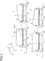
- Fig. 1 is a schematic diagram showing an embodiment of multi-purpose autonomous driving vehicles according to the present invention.
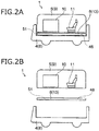
- Figs. 2A and 2B are diagrams exemplifying one of the multi-purpose autonomous driving vehicles of Fig. 1 .
- Figs. 3A and 3B are diagrams in which the application of the cabin layer is changed as compared with Figs. 2A and 2B .
- Fig. 4 is a schematic diagram showing an example in the cabin of Fig. 3A .
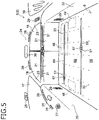
- Fig. 5 is a schematic diagram showing another example in the cabin.
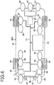
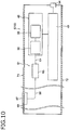
- Fig. 6 is a configuration diagram of the chassis layer.
- Fig. 7 is a configuration diagram of the connection layer.
- Fig. 8 is a configuration diagram of the cabin manager.
- Fig. 9 and Fig. 11 are configuration diagrams of electrical connection units.
- Fig. 10 and Fig. 12 are configuration diagrams of the connection layer as viewed in a cross section thereof.
- Figs. 13A to 13C are schematic diagrams showing other examples of an electrical connection portion.
- Figs. 14A to 14C are diagrams supplementally illustrating the multi-purpose autonomous driving vehicle.
- reference numeral 1 denotes the multi-purpose autonomous driving vehicle according to the present invention.
- Fig. 1 shows four multi-purpose autonomous driving vehicles 1, and an outer shape thereof is changed according to an application of a cabin layer 5 to be described later.
- the four multi-purpose autonomous driving vehicles 1 of Fig. 1 are assumed to have an application as an example of many applications.
- one of the four outer shapes will be described as a representative example.
- the multi-purpose autonomous driving vehicle 1 is an autonomous driving vehicle whose traveling is controlled by a wireless 3 using a cloud 2 (cloud service), and includes a portion to be a platform, a portion corresponding to a multi-purpose application, and a portion connecting the above portions.
- a fully autonomous driving vehicle corresponding to a Level 4 (Lv 4) ride share exclusive vehicle is used as the above autonomous driving vehicle in the present embodiment (which is not limited thereto).
- the multi-purpose autonomous driving vehicle 1 is configured such that the portion to be a platform, the portion corresponding to a multi-purpose application, and the connecting portion are stratified.
- the multi-purpose autonomous driving vehicle 1 includes a chassis layer 4, a cabin layer 5 and a connection layer 6.
- the chassis layer 4 corresponds to the portion to be a platform.
- the cabin layer 5 corresponds to the portion corresponding to a multi-purpose application.
- the connection layer 6 corresponds to the connecting portion.
- the chassis layer 4 corresponds to a "lower” layer portion among “upper, middle and lower” layer portions.
- the cabin layer 5 corresponds to an "upper” layer portion.
- the connection layer 6 corresponds to a "middle” later portion.
- Reference numeral 7 in Fig. 1 denotes the ground (traveling surface).
- arrows in Fig. 1 indicate a forward direction.
- the chassis layer 4 has a function for traveling by autonomous driving. In other words, the chassis layer 4 has a function of "travel, turn, stop" autonomously.
- the chassis layer 4 is a portion of traveling infrastructure.
- the chassis layer 4 is a common portion as can be seen from the four multi-purpose autonomous driving vehicles 1 of Fig. 1 . Even if the chassis layer 4 is a common portion, it may be divided according to sizes, such as a known mini vehicle size, an ordinary vehicle size, and a cargo vehicle size.
- the chassis layer 4 is the "chassis layer” described in the claims, but may be replaced by a “chassis 8" simply. Alternatively, the chassis layer 4 may be read as “platform” or “autonomous traveling unit” not particularly having a reference numeral.
- the cabin layer 5 is a portion functioning as a cabin 9 on an upper side of the chassis layer 4 (the chassis 8).
- the cabin layer 5 is configured such that the cabin 9 can cope with a multi-purpose application.
- a structure 10 and a seat 11 are fixed in the cabin 9, and in Fig. 3A and 3B , two seats 11 are fixed in the cabin 9.
- a structure 12 is fixed between the two seats 11.
- the multi-purpose autonomous driving vehicle 1 is autonomously distributed to the user in the absence of anything in the cabin 9. Then, the user can fix his/her own structure or simply to place personal items such as luggage in the cabin 9.
- the cabin layer 5 is understood to be a space for the user to "spend time" in the case of the application of Figs. 2A and 2B or Figs. 3A and 3B .
- the cabin layer 5 is the "cabin layer” described in the claims, but may be expressed as the cabin 9. Alternatively, the cabin layer 5 may be read as a "free space unit” or “service providing unit” not particularly having a reference numeral, for the user.
- Examples of the multi-purpose "application” will be given.
- Examples of the application include various applications ranging from ride share, logistics, transportation and retail, to hotels and personal services.
- Examples also include an application of a multi-purpose autonomous driving vehicle with various purposes changed in one day (an application of a multi-purpose autonomous driving vehicle with various purposes changed in several days or one week, not limited to one day).
- Other examples include applications in which the cabin 9 is, for example, a rental meeting room, a restaurant, a cafe, a cooking space, a laboratory, a gym, a barber, a convenience store... From the above applications, it can be seen that the amount of a power supply needed in the cabin layer 5 varies. Therefore, the present invention is useful.
- connection layer 6 is a portion disposed between the chassis layer 4 (chassis 8) and the cabin layer 5 (cabin 9) and can connect the chassis layer 4 and the cabin layer 5.
- the connection layer 6 is configured to be able to prevent an influence (for example, influence of noise to be described later) of the chassis layer 4 on the cabin layer 5 or an influence (for example, influence of water to be described later) of the cabin layer 5 on the chassis layer 4.
- the connection layer 6 is configured to be able to change the distribution of the power supply used in the cabin layer 5 based on the kind of application of the cabin layer 5, as will be understood from the following description.
- the connection layer 6 is a "connecting" infrastructure portion.
- connection layer 6 is a partition portion for shielding the influence from the bottom to the top or the influence from the top to the bottom (the partition portion can also be a portion of ensuring safety). Further, the connection layer 6 is a portion capable of changing the distribution of the power supply. The connection layer 6 is a portion separately disposed between the chassis layer 4 and the cabin layer 5 (Separate disposition is an example, which will be described later with reference to Figs. 14A to 14C ).
- connection layer 6 is the "connection layer” described in the claims, but may be replaced by, for example, a "plate module 13" simply. Alternatively, the connection layer 6 may be read as a “connection module” or the like not particularly having a reference numeral.
- the cabin 9 is configured as a space where four users (not shown) can relax and spend time.
- the portion of reference numeral 14 which can be seen in Fig. 4 shows the floor configuring the connection layer 6.
- the floor 14 is formed to be flat.
- four seats 15 are fixed as an example of the application of the cabin layer 5.
- the four seats 15 are fixed in a state where four users can sit facing each other by placing a small table 16 at the center.
- the four sheets 15 and the table 16 are fixed or placed on the floor 14 in advance according to the number of users and requests of the service provider (not shown) (this fixing is detachable fixing, but shall be fixing which can ensure the safety of the user during traveling).
- reference numeral 17 denotes a windshield
- reference numeral 18 denotes a side glass
- reference numeral 19 denotes a rear glass
- reference numeral 20 denotes a front panel
- reference numeral 21 denotes a side panel
- reference numeral 22 denotes a rear panel
- reference numeral 23 denotes a pillar
- reference numeral 24 denotes a ceiling.
- a display 25 is provided on the windshield 17.
- the display 25 displays various information such as travel information (operation information) and information from the outside.
- the display 25 of the present embodiment can also display videos of a television, a DVD, play of a moving image obtained through the Internet, or the like.
- the display 25 can be operated not only by a remote controller (not shown) but also by a smart speaker (not shown; a speaker with Al assistant function supporting interactive voice operation).
- the front panel 20 is provided with a wireless communication device 26.
- the wireless communication device 26 has a function of "Wi-Fi (registered trademark)".
- the wireless communication device 26 is provided to allow the user to use a smartphone, a tablet PC, a notebook PC, or the like in the cabin 9.
- the wireless communication device 26 is provided to enable connection of a sensor (not shown) installed in the cabin 9.
- Reference numeral 27 in the front panel 20 denotes a speaker.
- Reference numeral 28 denotes a register (air outlet of air conditioner), and reference numeral 29 denotes an AC outlet.
- the register 28 is also provided on the side glass 18 or the like.
- the AC outlet 29 is electrically connected to an expansion unit 52 (see Fig. 7 ) of the connection layer 6 to be described later.
- the AC outlet 29 is also provided to the rear panel 22 and the pillar 23 on the rear side (this is an example). Providing of the AC outlet 29 is optional, and only an AC outlet 67 to be described later of the connection layer 6 may be provided.
- the front panel 20 is provided with a storage portion (not shown) such as a so-called glove box.
- a watching unit 30 is provided on the side glass 18 or on the ceiling 24.
- the watching unit 30 is provided to obtain information on the presence or absence of the user and the safety confirmation of the user (whether the user is in a dangerous state for some reason or whether the user is sick), including the temperature and humidity in the cabin 9.
- the information obtained through the watching unit 30 is transmitted to the chassis layer 4 or transmitted to the cloud 2 via a signal relay unit 77 (see Fig. 14A ) of the connection layer 6 to be described later.
- Either one of the transmission and reception to and from the cloud 2 or the transmission and reception through the chassis layer 4, and the transmission and reception by the watching unit 30 may be adopted, for example (in the latter case, the communication unit is included in the configuration of the cabin layer 5).
- the watching unit 30 is, for example, "a device existing as a conductor" or "a device such as a service robot".
- the ceiling 24 is also provided with lighting equipment (not shown).
- a display 31 specialized for SNS (social networking service) is provided under the side glass 18, for example.
- the rear glass 19 is mirrored by a switch operation (the windshield 17 or the side glass 18 may have the same configuration).
- the front panel 20, the side panel 21 and the rear panel 22 have a changeable portion.
- the changeable portion is, for example, a portion which can be replaced when it is dirty, a portion such as a decorative board which changes the atmosphere of the interior according to the application, or a portion which is replaced as needed during maintenance.
- the changeable portion is a writable white board-like portion.
- the changeable portion may be all or part of the panel.
- the floor 14 is formed to be flat as described above.
- the floor 14 is formed in a manner of spreading a carpet specification mat.
- the floor 14 is formed in a state where it is safe to load luggage, for example in the form of a pallet.
- the floor 14 is formed in a state where it is safe to spill water or oil.
- the floor 14 is formed in a state where it is easy to clean.
- the floor 14 is formed in a state according to the multi-purpose application.
- Such a floor 14 has a plurality of AC outlets 67 to be described later.
- the AC outlet 67 configures an electrical connection unit 51 (see Fig. 7 ) of the connection layer 6 to be described later, and is a portion which can be changed in disposition, for example, by a slide, according to the application of the cabin layer 5.
- reference numeral 33 on the floor 14 denotes a structure fixing unit.
- the structure fixing unit 33 schematically shows a portion for fixing a structure (for example, the four seats 15 of Fig. 4 ) with "+".
- the structure fixing unit 33 is a portion configuring the connection layer 6.
- reference numeral 34 in the chassis layer 4 denotes a chassis body.
- reference numeral 35 denotes a wheel
- reference numeral 36 denotes an autonomous driving control unit
- reference numeral 37 denotes a steering function unit
- reference numeral 38 denotes a drive function unit
- reference numeral 39 denotes a brake function unit
- reference numeral 40 denotes a high voltage main battery (corresponding to the "second high voltage battery” described in the claims)
- reference numeral 41 denotes a wire harness for high voltage
- reference numeral 42 denotes an air conditioning function unit
- reference numeral 43 denotes a sensor function unit
- reference numeral 44 denotes a radar function unit
- reference numeral 45 denotes a dedicated communication device
- reference numeral 46 denotes an accident data recording device.
- Reference numeral 47 denotes a headlight, and the side on which the headlight is located is referred to as a front side.
- a known large capacity lithium ion battery is adopted as the high voltage main battery 40.
- the high voltage main battery 40 can be charged with AC 100 V or AC 200 V.
- CHMo registered trademark
- a known data communication module (DCM) is adopted as the dedicated communication device 45.
- EDR event data recorder
- the chassis layer 4 includes the above components (the configuration is an example).
- Fig. 7 schematically shows the connection layer 6 (plate module 13) superimposed on the chassis layer 4 (the chassis 8) (shown as an embodiment of the present invention).
- the connection layer 6 includes the cabin manager 48 as an important functional portion. Two cabin managers 48 are provided in the present embodiment.
- the above important function of the cabin manager 48 is a function of "changing the distribution of the power supply used in the cabin layer 5 according to the application of the cabin layer 5".
- the function of the cabin manager 48 is not a function to make the distribution of the power supply constant as in the related art.
- the function of the cabin manager 48 is a function suitable in a case of adopting the cabin layer 5 (cabin 9) corresponding to a multi-purpose application with the change of mobility services. That is, the function of the cabin manager 48 is different from the cabin manager in the related art in that the distribution of the power supply can be changed based on the kind of application of the cabin layer 5.
- the power supply can be changed to a distribution of 40% on a front side and 60% on a rear side of the vehicle based on the kind of application.
- the power supply can be changed to a distribution of 100% on the rear side according to another application.
- the cabin 9 can be monitored sequentially to change the distribution of the power supply according to yet another application. The above shows an example.
- the connection layer 6 includes, in addition to the cabin manager 48, the high voltage battery 49, an inverter 50 (see Fig. 8 ), the electrical connection unit 51, the expansion unit 52, and a second electrical connection unit 53.
- the high voltage battery 49 is a power supply for supplying power to the cabin layer 5, and a known high capacity lithium ion battery (400 V) is adopted.
- the high voltage battery 49 is to be an extended power supply for the high voltage main battery 40 (see Fig. 6 ) of the chassis layer 4.
- the high voltage battery 49 is connected to the cabin manager 48 disposed on the rear side.
- the high voltage battery 49 is provided with a charging unit 54.
- the connection layer 6 can be charged independently by providing the high voltage battery 49 with the charging unit 54 (the charging method is similar to that of the high voltage main battery 40 of the chassis layer 4).
- inverter 50 The details of the inverter 50 will be described later with reference to Fig. 8 .
- the details of the electrical connection unit 51 will be described later with reference to Fig. 7 to Fig. 12 .
- the expansion unit 52 is provided as a portion used in an expanded manner to connect the cabin layer 5. Specifically, in a case where the cabin layer 5 is provided with the AC outlet 29 (see Fig. 5 ), the expansion unit 52 is provided as a portion which can be connected to the AC outlet 29. In addition, if the cabin layer 5 needs to be supplied with a DC power supply, the expansion unit 52 is provided as a portion for this DC power supply.
- the second electrical connection unit 53 is provided as an electrical connection portion with the high voltage main battery 40 (see Fig. 6 ) of the chassis layer 4. In the present embodiment, the second electrical connection unit 53 is connected to the cabin manager 48 disposed on the front side. In the present embodiment, the cabin managers 48 disposed on the front side and the rear side are electrically connected by a connection line 32.
- the cabin manager 48 has a function capable of changing the distribution of the power supply (the high voltage battery 49 (if necessary, also the high voltage main battery 40 of the chassis layer 4)) used in the cabin layer 5 (see Figs. 2A to Fig. 5 ) based on the kind of application of the cabin layer 5.
- the cabin manager 48 as such a functional portion includes a cabin controller 55 (corresponding to the "controller” described in the claims).
- the cabin manager 48 includes, in addition to the cabin controller 55, a connector unit 56, a step-down DC-DC 57, and the inverter 50.
- the cabin controller 55 includes, although not shown particularly, a functional portion of a so-called microcomputer including a control unit, an arithmetic processing unit, a storage unit, or the like.
- the cabin controller 55 is used as an execution portion of a processing program which changes the distribution of the power supply based on the kind of application of the cabin layer 5 (see Figs. 2A to Fig. 5 ) (used as a portion to perform processing based on the "power distribution method" described in the claims).
- the cabin controller 55 includes a monitoring unit 58.
- the monitoring unit 58 is used as a portion which monitors the capacity state of the high voltage battery 49.
- the monitoring unit 58 in the present embodiment also monitors the capacity state of the high voltage main battery 40 of the chassis layer 4 (monitoring is optional). Since the cabin manager 48 includes the cabin controller 55 including the monitoring unit 58, the cabin manager 48 also has a function as a power management device.
- the process related to determination performed by the cabin controller 55 is based on data information stored in advance in the storage unit or data information from the monitoring unit 58. In addition, the process is also based on data information from the chassis layer 4 and/or the cabin layer 5, or data information from the cloud 2 (see Fig. 1 ).
- the connector unit 56 is configured to be an electrical connection portion with the high voltage battery 49 (the high voltage main battery 40 (see Fig. 11 ) of the chassis layer 4).
- the connector unit 56 is connected to the cabin controller 55 via an electric wire 59.
- the connector unit 56 is connected to the step-down DC-DC 57 via electric wires 60, 61.
- the step-down DC-DC 57 converts a DC (direct current) power supply into a DC (direct current) power supply, and here, a step-down converter which steps down DC 400 V to 48 V is adopted.
- Such a step-down DC-DC 57 is connected to the inverter 50 via an electric wire 62.
- the inverter 50 converts a DC (direct current) power supply to an AC (AC) power supply, and is provided to supply an AC (alternating current) power supply to the cabin layer 5 (see Figs. 2A to Fig. 5 ).
- the inverter 50 is connected to the cabin controller 55 via an electric wire 63.
- the inverter 50 is connected to the electrical connection unit 51 via an electric wire 64.
- seven inverters 50 and seven step-down DC-DCs 57 are provided, such that the power supply can be distributed to at most seven systems (the number is an example).
- the cabin manager 48 (cabin controller 55) is configured to be able to change the distribution of the power supply for at most seven systems based on the kind of application of the cabin layer 5 (see Figs. 2A to Fig. 5 ).
- the cabin manager 48 of the present embodiment includes the inverter 50 and the step-down DC-DC 57.
- the cabin manager 48 may be configured separately from the inverter 50 and the step-down DC-DC 57.
- the cabin manager 48 having a configuration in which the inverter 50 and the step-down DC-DC 57 are integrated as in the present embodiment may be referred to as a "cabin manager ECU" or a "cabin manager unit”.
- the electrical connection unit 51 is a portion connected to the electric wire 64 from the cabin manager 48 and is configured to be able to perform electrical connection with the cabin layer 5.
- the electrical connection unit 51 includes a power distribution spool 65 connected to the electric wire 64, an electric wire 66, and the AC outlet 67.
- the electric wire 66 is provided to be drawn and unwound from the power distribution spool 65.
- the AC outlet 67 is provided on an end of the electric wire 66.
- the power distribution spool 65 is used when changing the electrical connection position of the AC outlet 67.
- the power distribution spool 65 is fixed to a predetermined position of the connection layer 6 (plate module 13) by an appropriate manner.
- connection layer 6 (plate module 13) is provided with a customization region 68.
- the customization region 68 is set to be a region where the AC power supply distributed based on the kind of application of the cabin layer 5 can be electrically connected to the cabin layer 5 at an optimum position.
- the customization region 68 of the present embodiment corresponds to a region which is substantially the entire floor 14.
- Reference numeral 69 in Fig. 5 , Fig. 9 , and Fig. 11 denotes a slide portion.
- the slide portion 69 is formed as a portion used when changing the connection position of the AC outlet 67.
- the AC outlet 67 is guided to the slide portion 69, so that the connection position can be changed.
- the change of the connection position is effective to allow the electrical connection with the cabin layer 5 at a degree of freedom.
- reference numeral 70 in the electrical connection unit 51 denotes a power supply hub.
- the power supply hub 70 is provided in a case where there are a plurality of AC outlets 67 and among them a priority is desired.
- the connection layer 6 (plate module 13) is provided with a top plate portion 71 configuring the floor 14 and a bottom plate portion 72 disposed at a predetermined distance from the top plate portion 71.
- the top plate portion 71 and/or the bottom plate portion 72 have a function as a shield unit as a noise countermeasure, a function as a waterproof unit as a water countermeasure, and a function as a heat-resistant unit as a heat countermeasure.
- the noise countermeasure can be achieved
- the top plate portion 71 and the bottom plate portion 72 have a structure capable of ensuring sufficient rigidity. It is apparently that weight reduction can be achieved when, for example, aluminum is adopted as the material of the top plate portion 71 and the bottom plate portion 72.
- a retractable AC outlet 73 as shown in Fig. 13A is adopted.
- the AC outlet 73 is disposed at a predetermined position on the floor 14 or can be changed in position by a slide (not shown) or the like.
- an AC outlet 74 as shown in Fig. 13B is adopted.
- the AC outlet 74 can be turned in the direction of the arrow to change the orientation thereof.
- Fig. 13C shows a wireless power feeding type.
- a power feeding side coil unit 75 is provided below the floor 14.
- Reference numeral 76 denotes a power receiving side coil portion on a cabin layer 5 side.
- connection layer 6 is provided with a signal relay unit 77 configured to relay signals between the chassis layer 4 and the cabin layer 5.
- the signal relay unit 77 is connected to the cabin manager 48 (see Fig. 7 and Fig. 8 ) (this is an example).
- well-known CAN communication or the like is adopted for communication with a device mounted on the multi-purpose autonomous driving vehicle 1.
- the connection layer 6 may be integrated with the cabin layer 5.
- the connection layer 6 may be integrated with the chassis layer 4.
Abstract
Description
- The present invention relates to an invention such as a system suitable for mobility service in an autonomous driving vehicle. The present invention specifically relates to an invention of a system of a connection layer disposed between a chassis layer having a function for traveling and a cabin layer functioning as a cabin on an upper side of the chassis layer. The present invention also relates to an invention of a multi-purpose autonomous driving vehicle including the above layers. The present invention further relates to inventions of a cabin manager and a power distribution method adopted in a connection layer system.
- In recent years, proposals for mobility services have begun to be made in anticipation of the prospect of autonomous driving vehicles. For example, in
JP-A-2015-92327 - In the future, autonomous driving vehicles are considered to adopt a cabin corresponding to multi-purpose applications as the mobility services change.
- The present invention has been made in view of the above circumstances, and an object of the present invention is to provide a system suitable for adopting a cabin corresponding to a multi-purpose application. Another object of the present invention is to provide a multi-purpose autonomous driving vehicle in which this system is adopted, and a cabin manager and a power distribution method adopted in the above system.
- A connection layer system of the present invention according to an
aspect 1 for solving the above problems includes a cabin manager disposed between a chassis layer and a cabin layer, wherein the chassis layer has a function for traveling and the cabin layer functions as a cabin on an upper side of the chassis layer, and wherein the cabin manager includes a controller configured to change distribution of a power supply used in the cabin layer based on a kind of application of the cabin layer. - According to the invention having characteristics of the
aspect 1, since the system includes the cabin manager, the cabin manager can change the distribution of the power supply based on the kind of the application of the cabin layer. In other words, since the cabin manager is included, the power supply can be distributed to high priority locations in the cabin layer. Examples of the kind of the application include various applications ranging from ride share, logistics, transportation and retail, to hotels and personal services. Examples also include an application of a multi-purpose autonomous driving vehicle with various purposes changed in one day (an application of a multi-purpose autonomous driving vehicle with various purposes changed in several days or one week, not limited to one day). Other examples include applications in which the cabin is, for example, a rental meeting room, a restaurant, a cafe, a cooking space, a laboratory, a gym, a barber, a convenience store... In the present invention, since the distribution of the power supply can be changed based on the kind of application of thecabin layer 5, for example, the power supply can be changed to a distribution of 40% on a front side and 60% on a rear side of the vehicle based on the kind of application. In addition, the power supply can be changed to a distribution of 100% on the rear side according to another application. Further, the cabin can be monitored sequentially to change the distribution of the power supply according to yet another application. As known from the above, the present invention does not make the distribution of the power supply constant as in the related art. The present invention is suitable in a case of adopting a cabin corresponding to a multi-purpose application with the change of mobility services. That is, the function of the cabin manager is different from the cabin manager in the related art in that the distribution of the power supply can be changed based on the kind of application of the cabin layer. - The invention described in an aspect 2 relates to the connection layer system according to the
aspect 1, which further includes a first electrical connection unit connected to the cabin manager and configured to perform electrical connection with the cabin layer. - According to the invention having characteristics of the aspect 2, since the system includes the first electrical connection unit in the configuration thereof, the power supply distributed based on the kind of application of the cabin layer can be supplied to the cabin layer via the first electrical connection unit. Since the first electrical connection unit is included, it is apparently that the electrical connection with the cabin layer can be facilitated. Examples of the configuration of the first electrical connection unit include an electrical connection portion with the cabin layer (for example, the AC outlet in an
aspect 4 and/or a connection portion for DC not particularly listed in the aspects) and other configurations used for connection with the cabin manager (for example, an electric wire). - The invention described in an
aspect 3 relates to the connection layer system according to the aspect 2, which further includes a customization region configured to change an arrangement of the first electrical connection unit based on the kind of application of the cabin layer. - According to the invention having characteristics of the
aspect 3, since the system includes the customization region, the arrangement of the first electrical connection unit (particularly the arrangement of the electrical connection portion with the cabin layer) can have a degree of freedom. Accordingly, the power supply distributed based on the kind of application of the cabin layer can be electrically connected to the cabin layer at an optimum position (the power supply can be supplied). In order to allow the degree of freedom in the arrangement of the electrical connection portion, it is effective to include, for example, a power distribution spool in the configuration of the first electrical connection unit. The power distribution spool is a member capable of drawing the electric wire and unwinding the drawn electric wire, and it is apparently that the electrical connection position can be easily changed with such a member. - The invention described in an
aspect 4 relates to the connection layer system according to theaspect 2 or 3, and the first electrical connection unit includes an AC outlet. - According to the invention having characteristics of the
aspect 4, the electrical connection portion with the cabin layer can be the AC outlet. Since the present invention enables the supply of the AC power supply, for example, consumer devices (or office devices, information devices, or the like) can be used on a cabin layer side, and the usability can be improved. It is apparently that, in the present invention, an effective electrical connection unit is obtained in the inventions described inaspects - The invention described in an
aspect 5 relates to the connection layer system according to any one of aspects 2 to 4, which further includes a first high voltage battery serving as the power supply, and an inverter connected to the first high voltage battery. - According to the invention having characteristics of the
aspect 5, since the system includes the first high voltage battery and the inverter in the configuration thereof, the AC power supply distributed based on the kind of application of the cabin layer can be supplied to the cabin layer via the first electrical connection unit. The present invention is effective in a case of using, for example, consumer devices, office devices, information devices, or the like on the cabin layer side. For example, taking a consumer device as an example, it is effective in a case of using a device having a wide range of power consumption, such as an IH device or a dryer. - The invention described in an
aspect 6 relates to the connection layer system according to theaspect 5, and the cabin manager includes, a monitoring unit configured to monitor a capacity state of the first high voltage battery. - According to the invention having characteristics of the
aspect 6, since the cabin manager includes the monitoring unit in the configuration thereof, the monitoring unit can be used to monitor the capacity state of the first high voltage battery, and information of the monitoring result can be reflected, for example, in the distribution of the power supply. It is apparently that the present invention is effective in terms of power management. - The invention described in an aspect 7 relates to the connection layer system according to the
aspect - According to the invention having characteristics of the aspect 7, since the system includes the charging unit, the connection layer alone can charge the first high voltage battery. It is apparently that the present invention is particularly effective in the inventions described in an
aspect 13 below. - The invention described in an
aspect 8 relates to the connection layer system according to any one of aspects 2 to 4, which further includes a second electrical connection unit configured to perform electrical connection, and an inverter connected to the second electrical connection unit, and the second electrical connection unit is connected to a second high voltage battery provided on the chassis layer and serving as another power supply. - According to the invention having characteristics of the
aspect 8, since the system includes the second electrical connection unit and the inverter connected to the second electrical connection unit, and the second electrical connection unit is connected to the second high voltage battery provided on the chassis layer, the AC power supply distributed based on the kind of application of the cabin layer can be supplied to the cabin layer using the second high voltage battery. The present invention is effective in a case of using, for example, consumer devices, office devices, information devices, or the like on the cabin layer side. Theaspect 8 relates to an invention focusing on the utilization of the second high voltage battery, unlike the invention described in theaspect 5. - The invention described in an
aspect 9 relates to the connection layer system according to any one of aspects 2 to 4, which further includes a second electrical connection unit configured to perform electrical connection, a first high voltage battery serving as the power supply, and an inverter configured to connect the second electrical connection unit and the first high voltage battery, and the second electrical connection unit is connected to a second high voltage battery provided on the chassis layer and serving as another power supply. - According to the invention having characteristics of the
aspect 9, since the system includes the first high voltage battery and the inverter, the second electrical connection unit connected to the inverter is included, and the second electrical connection unit is connected to the second high voltage battery provided on the chassis layer, the AC power supply distributed based on the kind of application of the cabin layer can be supplied to the cabin layer using the first high voltage battery and the second high voltage battery. The present invention is effective in a case of using, for example, consumer devices, office devices, information devices, or the like on the cabin layer side. Theaspect 9 relates to an invention focusing on the utilization of the first high voltage battery of the connection layer own and the second high voltage battery. - The invention described in an
aspect 10 relates to the connection layer system according to any one ofaspects 1 to 9, which further includes a signal relay unit configured to perform signal relay between the chassis layer and the cabin layer. - According to the invention having characteristics of the
aspect 10, since the system includes the signal relay unit in the configuration thereof, the traveling speed can be displayed on a display device on the cabin layer side, based on a signal (a signal of a traveling speed or a traveling position) related to, for example, traveling information obtained on a chassis layer side. In addition, an air conditioning system can also be activated on the chassis layer side based on a signal related to temperature information in the cabin obtained on the cabin layer side. Examples of the signal related to other information include a signal of measured values obtained by various sensors on the cabin layer side, a signal at a switch operation to notify an emergency, a signal indicating an emergency coming from outside, and a signal related to communication including the Internet. - The invention described in an
aspect 11 relates to the connection layer system according to any one ofaspects 1 to 10, which further includes at least one of a shield unit as a noise countermeasure disposed between the chassis layer and the cabin layer, a waterproof unit as a water countermeasure disposed between the chassis layer and the cabin layer, a heat-resistant unit as a heat countermeasure disposed between the chassis layer and the cabin layer, and a structure fixing unit capable of fixing a structure used in the cabin layer. - According to the invention having characteristics of the
aspect 11, since the system includes the shield unit, the waterproof unit, the heat-resistant unit and the structure fixing unit in the configuration thereof, the noise countermeasure can be achieved in the case of the shield unit, the water countermeasure can be achieved in the case of the waterproof unit, the heat countermeasure can be achieved in the case of the heat-resistant unit, and fixation of the structure can be achieved in the case of the structure fixing unit. - A multi-purpose autonomous driving vehicle of the present invention according to an
aspect 12 for solving the above problems includes: a chassis layer having a function for traveling; a cabin layer functioning as a cabin on an upper side of the chassis layer; and a connection layer disposed between the chassis layer and the cabin layer, and the connection layer system according to any one ofaspects 1 to 11 is adopted as a system in the connection layer. - According to the invention having characteristics of the
aspect 12, since the connection layer system is adopted, an autonomous driving vehicle corresponding to a multi-purpose application can be provided. - The invention described in an
aspect 13 relates to the multi-purpose autonomous driving vehicle according to theaspect 12, and the connection layer is separate from the chassis layer and the cabin layer. - According to the invention having characteristics of the
aspect 13, the connection layer can be separate from the chassis layer and the cabin layer. According to the present invention, one form of the connection layer in the multi-purpose autonomous driving vehicle can be provided. - The invention described in an
aspect 14 relates to the multi-purpose autonomous driving vehicle according to theaspect 12, and the connection layer is integrated with either one of the chassis layer and the cabin layer. - According to the invention having characteristics of the
aspect 14, the connection layer can be integrated with either one of the chassis layer and the cabin layer. According to the present invention, one form of the connection layer in the multi-purpose autonomous driving vehicle can be provided. - A cabin manager of the present invention according to an
aspect 15 for solving the above problems includes a controller configured to change distribution of a power supply used in a cabin layer based on a type of application of the cabin layer, wherein the controller is disposed on a connection layer provided between a chassis layer having a function for traveling and the cabin layer functioning as a cabin on an upper side of the chassis layer. - According to the invention having characteristics of the
aspect 15, the distribution of the power supply can be changed based on the kind of application of the cabin layer. In other words, the power supply can be distributed to high priority locations in the cabin layer. Examples of the application include those mentioned in the description for theaspect 1, for example. The present invention does not make the distribution of the power supply constant. The present invention is suitable in a case of adopting a cabin corresponding to a multi-purpose application with the change of mobility services. That is, the distribution of the power supply can be changed based on the kind of application of the cabin layer. - A power distribution method in a connection layer system of the present invention according to an
aspect 16 for solving the above problems includes performing a process of changing distribution of a power supply by a controller based on a kind of application of a cabin layer, wherein the connection layer system includes a cabin manager disposed on a connection layer disposed between a chassis layer having a function for traveling and the cabin layer functioning as a cabin on an upper side of the chassis layer, and the cabin manager includes the controller configured to distribute the power supply used in the cabin layer. - According to the invention having characteristics of the
aspect 16, the distribution of the power supply can be changed based on the kind of application of the cabin layer by adopting the method of the present invention. In other words, the power supply can be distributed to high priority locations in the cabin layer. Examples of the application include those mentioned in the description for theaspect 1. The present invention is not a method of making the distribution of the power supply constant. The present invention is a method suitable in a case of adopting a cabin corresponding to a multi-purpose application with the change of mobility services. That is, it is a method in which the distribution of the power supply can be changed based on the kind of application of the cabin layer. - According to the present invention, the effect of being able to adopt a cabin corresponding to a multi-purpose application is obtained.
-
-
Fig. 1 is a schematic diagram showing an embodiment of multi-purpose autonomous driving vehicles according to the present invention. -
Figs. 2A and 2B are diagrams exemplifying one of the multi-purpose autonomous driving vehicles ofFig. 1 , in whichFig. 2A is a diagram illustrating an application of a cabin layer, andFig. 2B is a configuration diagram of the multi-purpose autonomous driving vehicle ofFig. 2A . -
Figs. 3A and 3B are diagrams in which the application of the cabin layer is changed as compared withFigs. 2A and 2B , in whichFig. 3A is a diagram illustrating the application, andFig. 3B is a configuration diagram of the multi-purpose autonomous driving vehicle ofFig. 3A . -
Fig. 4 is a schematic diagram showing an example in the cabin ofFig. 3A . -
Fig. 5 is a schematic diagram showing another example in the cabin. -
Fig. 6 is a configuration diagram of a chassis layer. -
Fig. 7 is a configuration diagram of a connection layer. -
Fig. 8 is a configuration diagram of a cabin manager. -
Fig. 9 is a configuration diagram of an electrical connection unit. -
Fig. 10 is a configuration diagram of the connection layer as viewed in a cross section thereof. -
Fig. 11 is a configuration diagram of an electrical connection unit. -
Fig. 12 is a configuration diagram of the connection layer as viewed in a cross section thereof. -
Figs. 13A to 13C are schematic diagrams showing other examples of an electrical connection portion. -
Figs. 14A to 14C are diagrams supplementally illustrating the multi-purpose autonomous driving vehicle. - A multi-purpose autonomous driving vehicle adopting a cabin corresponding to a multi-purpose application includes: a chassis layer having a function for traveling; a cabin layer functioning as a cabin on an upper side of the chassis layer; and a connection layer disposed between the chassis layer and the cabin layer. A system of the connection layer includes a cabin manager disposed between the chassis layer and the cabin layer. The cabin manager includes a controller in a configuration thereof, and the controller has a function of changing distribution of a power supply used in the cabin layer according to an application of the cabin layer.
- Hereinafter, an embodiment will be described with reference to the drawings.
Fig. 1 is a schematic diagram showing an embodiment of multi-purpose autonomous driving vehicles according to the present invention.Figs. 2A and 2B are diagrams exemplifying one of the multi-purpose autonomous driving vehicles ofFig. 1 .Figs. 3A and 3B are diagrams in which the application of the cabin layer is changed as compared withFigs. 2A and 2B .Fig. 4 is a schematic diagram showing an example in the cabin ofFig. 3A .Fig. 5 is a schematic diagram showing another example in the cabin.Fig. 6 is a configuration diagram of the chassis layer.Fig. 7 is a configuration diagram of the connection layer.Fig. 8 is a configuration diagram of the cabin manager.Fig. 9 andFig. 11 are configuration diagrams of electrical connection units.Fig. 10 andFig. 12 are configuration diagrams of the connection layer as viewed in a cross section thereof.Figs. 13A to 13C are schematic diagrams showing other examples of an electrical connection portion.Figs. 14A to 14C are diagrams supplementally illustrating the multi-purpose autonomous driving vehicle. - In the following description, shapes, materials, numerical values, directions or the like are examples for facilitating the understanding of the present invention, and can be can be changed as appropriate based on the kind of application, purpose, specification, or the like.
- In
Fig. 1 ,reference numeral 1 denotes the multi-purpose autonomous driving vehicle according to the present invention.Fig. 1 shows four multi-purposeautonomous driving vehicles 1, and an outer shape thereof is changed according to an application of acabin layer 5 to be described later. The four multi-purposeautonomous driving vehicles 1 ofFig. 1 are assumed to have an application as an example of many applications. Hereinafter, one of the four outer shapes will be described as a representative example. - In
Fig. 1 to Fig. 3B , the multi-purposeautonomous driving vehicle 1 is an autonomous driving vehicle whose traveling is controlled by awireless 3 using a cloud 2 (cloud service), and includes a portion to be a platform, a portion corresponding to a multi-purpose application, and a portion connecting the above portions. A fully autonomous driving vehicle corresponding to a Level 4 (Lv 4) ride share exclusive vehicle is used as the above autonomous driving vehicle in the present embodiment (which is not limited thereto). The multi-purposeautonomous driving vehicle 1 is configured such that the portion to be a platform, the portion corresponding to a multi-purpose application, and the connecting portion are stratified. Specifically, the multi-purposeautonomous driving vehicle 1 includes achassis layer 4, acabin layer 5 and aconnection layer 6. Thechassis layer 4 corresponds to the portion to be a platform. Thecabin layer 5 corresponds to the portion corresponding to a multi-purpose application. Theconnection layer 6 corresponds to the connecting portion. Thechassis layer 4 corresponds to a "lower" layer portion among "upper, middle and lower" layer portions. Thecabin layer 5 corresponds to an "upper" layer portion. Theconnection layer 6 corresponds to a "middle" later portion. Reference numeral 7 inFig. 1 denotes the ground (traveling surface). In addition, arrows inFig. 1 indicate a forward direction. - In
Fig. 1 to Fig. 3B , thechassis layer 4 has a function for traveling by autonomous driving. In other words, thechassis layer 4 has a function of "travel, turn, stop" autonomously. Thechassis layer 4 is a portion of traveling infrastructure. Thechassis layer 4 is a common portion as can be seen from the four multi-purposeautonomous driving vehicles 1 ofFig. 1 . Even if thechassis layer 4 is a common portion, it may be divided according to sizes, such as a known mini vehicle size, an ordinary vehicle size, and a cargo vehicle size. - The
chassis layer 4 is the "chassis layer" described in the claims, but may be replaced by a "chassis 8" simply. Alternatively, thechassis layer 4 may be read as "platform" or "autonomous traveling unit" not particularly having a reference numeral. - In
Fig. 1 to Fig. 3B , thecabin layer 5 is a portion functioning as acabin 9 on an upper side of the chassis layer 4 (the chassis 8). Thecabin layer 5 is configured such that thecabin 9 can cope with a multi-purpose application. InFigs. 2A and 2B , astructure 10 and aseat 11 are fixed in thecabin 9, and inFig. 3A and 3B , twoseats 11 are fixed in thecabin 9. In addition, inFigs. 3A and 3B , astructure 12 is fixed between the twoseats 11. The multi-purposeautonomous driving vehicle 1 is autonomously distributed to the user in the absence of anything in thecabin 9. Then, the user can fix his/her own structure or simply to place personal items such as luggage in thecabin 9. Thecabin layer 5 is understood to be a space for the user to "spend time" in the case of the application ofFigs. 2A and 2B orFigs. 3A and 3B . - The
cabin layer 5 is the "cabin layer" described in the claims, but may be expressed as thecabin 9. Alternatively, thecabin layer 5 may be read as a "free space unit" or "service providing unit" not particularly having a reference numeral, for the user. - Here, examples of the multi-purpose "application" will be given. Examples of the application include various applications ranging from ride share, logistics, transportation and retail, to hotels and personal services. Examples also include an application of a multi-purpose autonomous driving vehicle with various purposes changed in one day (an application of a multi-purpose autonomous driving vehicle with various purposes changed in several days or one week, not limited to one day). Other examples include applications in which the
cabin 9 is, for example, a rental meeting room, a restaurant, a cafe, a cooking space, a laboratory, a gym, a barber, a convenience store... From the above applications, it can be seen that the amount of a power supply needed in thecabin layer 5 varies. Therefore, the present invention is useful. - In
Fig. 1 to Fig. 3B , theconnection layer 6 is a portion disposed between the chassis layer 4 (chassis 8) and the cabin layer 5 (cabin 9) and can connect thechassis layer 4 and thecabin layer 5. In addition, theconnection layer 6 is configured to be able to prevent an influence (for example, influence of noise to be described later) of thechassis layer 4 on thecabin layer 5 or an influence (for example, influence of water to be described later) of thecabin layer 5 on thechassis layer 4. Further, theconnection layer 6 is configured to be able to change the distribution of the power supply used in thecabin layer 5 based on the kind of application of thecabin layer 5, as will be understood from the following description. Theconnection layer 6 is a "connecting" infrastructure portion. In addition, theconnection layer 6 is a partition portion for shielding the influence from the bottom to the top or the influence from the top to the bottom (the partition portion can also be a portion of ensuring safety). Further, theconnection layer 6 is a portion capable of changing the distribution of the power supply. Theconnection layer 6 is a portion separately disposed between thechassis layer 4 and the cabin layer 5 (Separate disposition is an example, which will be described later with reference toFigs. 14A to 14C ). - The
connection layer 6 is the "connection layer" described in the claims, but may be replaced by, for example, a "plate module 13" simply. Alternatively, theconnection layer 6 may be read as a "connection module" or the like not particularly having a reference numeral. - In
Fig. 4 , thecabin 9 is configured as a space where four users (not shown) can relax and spend time. The portion ofreference numeral 14 which can be seen inFig. 4 shows the floor configuring theconnection layer 6. Thefloor 14 is formed to be flat. On thefloor 14, fourseats 15 are fixed as an example of the application of thecabin layer 5. The fourseats 15 are fixed in a state where four users can sit facing each other by placing a small table 16 at the center. The foursheets 15 and the table 16 are fixed or placed on thefloor 14 in advance according to the number of users and requests of the service provider (not shown) (this fixing is detachable fixing, but shall be fixing which can ensure the safety of the user during traveling). - In
Fig. 4 , as portions pertaining to the configuration of thecabin layer 5,reference numeral 17 denotes a windshield,reference numeral 18 denotes a side glass,reference numeral 19 denotes a rear glass,reference numeral 20 denotes a front panel,reference numeral 21 denotes a side panel,reference numeral 22 denotes a rear panel,reference numeral 23 denotes a pillar, andreference numeral 24 denotes a ceiling. As described above, since the vehicle is a fully autonomous driving vehicle corresponding to level 4 (Lv 4), it is apparently that there is no steering wheel, accelerator pedal, brake pedal or the like. - In
Fig. 5 , as another example of thecabin 9, the following is provided. That is, adisplay 25 is provided on thewindshield 17. Thedisplay 25 displays various information such as travel information (operation information) and information from the outside. Thedisplay 25 of the present embodiment can also display videos of a television, a DVD, play of a moving image obtained through the Internet, or the like. Thedisplay 25 can be operated not only by a remote controller (not shown) but also by a smart speaker (not shown; a speaker with Al assistant function supporting interactive voice operation). Thefront panel 20 is provided with awireless communication device 26. Thewireless communication device 26 has a function of "Wi-Fi (registered trademark)". Thewireless communication device 26 is provided to allow the user to use a smartphone, a tablet PC, a notebook PC, or the like in thecabin 9. In addition, thewireless communication device 26 is provided to enable connection of a sensor (not shown) installed in thecabin 9. -
Reference numeral 27 in thefront panel 20 denotes a speaker.Reference numeral 28 denotes a register (air outlet of air conditioner), andreference numeral 29 denotes an AC outlet. Theregister 28 is also provided on theside glass 18 or the like. TheAC outlet 29 is electrically connected to an expansion unit 52 (seeFig. 7 ) of theconnection layer 6 to be described later. In present embodiment, theAC outlet 29 is also provided to therear panel 22 and thepillar 23 on the rear side (this is an example). Providing of theAC outlet 29 is optional, and only anAC outlet 67 to be described later of theconnection layer 6 may be provided. Thefront panel 20 is provided with a storage portion (not shown) such as a so-called glove box. - A watching
unit 30 is provided on theside glass 18 or on theceiling 24. The watchingunit 30 is provided to obtain information on the presence or absence of the user and the safety confirmation of the user (whether the user is in a dangerous state for some reason or whether the user is sick), including the temperature and humidity in thecabin 9. The information obtained through the watchingunit 30 is transmitted to thechassis layer 4 or transmitted to the cloud 2 via a signal relay unit 77 (seeFig. 14A ) of theconnection layer 6 to be described later. Either one of the transmission and reception to and from the cloud 2 or the transmission and reception through thechassis layer 4, and the transmission and reception by the watchingunit 30 may be adopted, for example (in the latter case, the communication unit is included in the configuration of the cabin layer 5). The watchingunit 30 is, for example, "a device existing as a conductor" or "a device such as a service robot". - In addition to the watching
unit 30, theceiling 24 is also provided with lighting equipment (not shown). Under theside glass 18, for example, adisplay 31 specialized for SNS (social networking service) is provided. Therear glass 19 is mirrored by a switch operation (thewindshield 17 or theside glass 18 may have the same configuration). Thefront panel 20, theside panel 21 and therear panel 22 have a changeable portion. The changeable portion is, for example, a portion which can be replaced when it is dirty, a portion such as a decorative board which changes the atmosphere of the interior according to the application, or a portion which is replaced as needed during maintenance. In addition, for applications such as conference rooms and individual learning chores, the changeable portion is a writable white board-like portion. The changeable portion may be all or part of the panel. - In
Fig. 5 , thefloor 14 is formed to be flat as described above. In a case where a person gets on the vehicle, for example, thefloor 14 is formed in a manner of spreading a carpet specification mat. When being used as a transport vehicle, thefloor 14 is formed in a state where it is safe to load luggage, for example in the form of a pallet. In addition, in a case of being used as a kitchen car, for example, thefloor 14 is formed in a state where it is safe to spill water or oil. Further, in a case of being used as a barber or a beauty salon, thefloor 14 is formed in a state where it is easy to clean. Thefloor 14 is formed in a state according to the multi-purpose application. Such afloor 14 has a plurality ofAC outlets 67 to be described later. TheAC outlet 67 configures an electrical connection unit 51 (seeFig. 7 ) of theconnection layer 6 to be described later, and is a portion which can be changed in disposition, for example, by a slide, according to the application of thecabin layer 5. - In
Fig. 5 ,reference numeral 33 on thefloor 14 denotes a structure fixing unit. Thestructure fixing unit 33 schematically shows a portion for fixing a structure (for example, the fourseats 15 ofFig. 4 ) with "+". Thestructure fixing unit 33 is a portion configuring theconnection layer 6. Under thefloor 14, acabin manager 48 to be described later of theconnection layer 6 and ahigh voltage battery 49 are disposed. - In
Fig. 6 ,reference numeral 34 in the chassis layer 4 (the chassis 8) denotes a chassis body. In addition,reference numeral 35 denotes a wheel,reference numeral 36 denotes an autonomous driving control unit,reference numeral 37 denotes a steering function unit,reference numeral 38 denotes a drive function unit,reference numeral 39 denotes a brake function unit,reference numeral 40 denotes a high voltage main battery (corresponding to the "second high voltage battery" described in the claims),reference numeral 41 denotes a wire harness for high voltage,reference numeral 42 denotes an air conditioning function unit,reference numeral 43 denotes a sensor function unit,reference numeral 44 denotes a radar function unit,reference numeral 45 denotes a dedicated communication device, andreference numeral 46 denotes an accident data recording device.Reference numeral 47 denotes a headlight, and the side on which the headlight is located is referred to as a front side. A known large capacity lithium ion battery is adopted as the high voltagemain battery 40. The high voltagemain battery 40 can be charged with AC 100 V or AC 200 V. In addition, it is naturally possible to perform rapid charging according to a standard (CHAdeMo (registered trademark)) at least widespread in Japan. A known data communication module (DCM) is adopted as thededicated communication device 45. Further, a known event data recorder (EDR) is adopted as the accidentdata recording device 46. Thechassis layer 4 includes the above components (the configuration is an example). -
Fig. 7 schematically shows the connection layer 6 (plate module 13) superimposed on the chassis layer 4 (the chassis 8) (shown as an embodiment of the present invention). Theconnection layer 6 includes thecabin manager 48 as an important functional portion. Twocabin managers 48 are provided in the present embodiment. - The above important function of the
cabin manager 48 is a function of "changing the distribution of the power supply used in thecabin layer 5 according to the application of thecabin layer 5". The function of thecabin manager 48 is not a function to make the distribution of the power supply constant as in the related art. The function of thecabin manager 48 is a function suitable in a case of adopting the cabin layer 5 (cabin 9) corresponding to a multi-purpose application with the change of mobility services. That is, the function of thecabin manager 48 is different from the cabin manager in the related art in that the distribution of the power supply can be changed based on the kind of application of thecabin layer 5. - According to the
cabin manager 48, since the distribution of the power supply can be changed based on the kind of application of thecabin layer 5, for example, the power supply can be changed to a distribution of 40% on a front side and 60% on a rear side of the vehicle based on the kind of application. In addition, the power supply can be changed to a distribution of 100% on the rear side according to another application. Further, thecabin 9 can be monitored sequentially to change the distribution of the power supply according to yet another application. The above shows an example. - The details of the
cabin manager 48 will be described later with reference toFig. 8 . - The
connection layer 6 includes, in addition to thecabin manager 48, thehigh voltage battery 49, an inverter 50 (seeFig. 8 ), theelectrical connection unit 51, theexpansion unit 52, and a secondelectrical connection unit 53. Thehigh voltage battery 49 is a power supply for supplying power to thecabin layer 5, and a known high capacity lithium ion battery (400 V) is adopted. In the present embodiment, thehigh voltage battery 49 is to be an extended power supply for the high voltage main battery 40 (seeFig. 6 ) of thechassis layer 4. In the present embodiment, thehigh voltage battery 49 is connected to thecabin manager 48 disposed on the rear side. Thehigh voltage battery 49 is provided with a chargingunit 54. Theconnection layer 6 can be charged independently by providing thehigh voltage battery 49 with the charging unit 54 (the charging method is similar to that of the high voltagemain battery 40 of the chassis layer 4). - The details of the
inverter 50 will be described later with reference toFig. 8 . The details of theelectrical connection unit 51 will be described later with reference toFig. 7 to Fig. 12 . - The
expansion unit 52 is provided as a portion used in an expanded manner to connect thecabin layer 5. Specifically, in a case where thecabin layer 5 is provided with the AC outlet 29 (seeFig. 5 ), theexpansion unit 52 is provided as a portion which can be connected to theAC outlet 29. In addition, if thecabin layer 5 needs to be supplied with a DC power supply, theexpansion unit 52 is provided as a portion for this DC power supply. The secondelectrical connection unit 53 is provided as an electrical connection portion with the high voltage main battery 40 (seeFig. 6 ) of thechassis layer 4. In the present embodiment, the secondelectrical connection unit 53 is connected to thecabin manager 48 disposed on the front side. In the present embodiment, thecabin managers 48 disposed on the front side and the rear side are electrically connected by aconnection line 32. - In
Fig. 8 , thecabin manager 48 has a function capable of changing the distribution of the power supply (the high voltage battery 49 (if necessary, also the high voltagemain battery 40 of the chassis layer 4)) used in the cabin layer 5 (seeFigs. 2A to Fig. 5 ) based on the kind of application of thecabin layer 5. Thecabin manager 48 as such a functional portion includes a cabin controller 55 (corresponding to the "controller" described in the claims). In addition, thecabin manager 48 includes, in addition to thecabin controller 55, aconnector unit 56, a step-down DC-DC 57, and theinverter 50. - The
cabin controller 55 includes, although not shown particularly, a functional portion of a so-called microcomputer including a control unit, an arithmetic processing unit, a storage unit, or the like. Thecabin controller 55 is used as an execution portion of a processing program which changes the distribution of the power supply based on the kind of application of the cabin layer 5 (seeFigs. 2A to Fig. 5 ) (used as a portion to perform processing based on the "power distribution method" described in the claims). In addition, thecabin controller 55 includes amonitoring unit 58. Themonitoring unit 58 is used as a portion which monitors the capacity state of thehigh voltage battery 49. Themonitoring unit 58 in the present embodiment also monitors the capacity state of the high voltagemain battery 40 of the chassis layer 4 (monitoring is optional). Since thecabin manager 48 includes thecabin controller 55 including themonitoring unit 58, thecabin manager 48 also has a function as a power management device. - The process related to determination performed by the
cabin controller 55 is based on data information stored in advance in the storage unit or data information from themonitoring unit 58. In addition, the process is also based on data information from thechassis layer 4 and/or thecabin layer 5, or data information from the cloud 2 (seeFig. 1 ). - The
connector unit 56 is configured to be an electrical connection portion with the high voltage battery 49 (the high voltage main battery 40 (seeFig. 11 ) of the chassis layer 4). Theconnector unit 56 is connected to thecabin controller 55 via anelectric wire 59. In addition, theconnector unit 56 is connected to the step-down DC-DC 57 viaelectric wires DC 57 converts a DC (direct current) power supply into a DC (direct current) power supply, and here, a step-down converter which steps down DC 400 V to 48 V is adopted. Such a step-down DC-DC 57 is connected to theinverter 50 via anelectric wire 62. Theinverter 50 converts a DC (direct current) power supply to an AC (AC) power supply, and is provided to supply an AC (alternating current) power supply to the cabin layer 5 (seeFigs. 2A to Fig. 5 ). Theinverter 50 is connected to thecabin controller 55 via anelectric wire 63. In addition, theinverter 50 is connected to theelectrical connection unit 51 via anelectric wire 64. In the present embodiment, seveninverters 50 and seven step-down DC-DCs 57 are provided, such that the power supply can be distributed to at most seven systems (the number is an example). - As described above, the cabin manager 48 (cabin controller 55) is configured to be able to change the distribution of the power supply for at most seven systems based on the kind of application of the cabin layer 5 (see
Figs. 2A to Fig. 5 ). - The
cabin manager 48 of the present embodiment includes theinverter 50 and the step-down DC-DC 57. However, thecabin manager 48 may be configured separately from theinverter 50 and the step-down DC-DC 57. In addition, thecabin manager 48 having a configuration in which theinverter 50 and the step-down DC-DC 57 are integrated as in the present embodiment may be referred to as a "cabin manager ECU" or a "cabin manager unit". - In
Fig. 7 to Fig. 12 , theelectrical connection unit 51 is a portion connected to theelectric wire 64 from thecabin manager 48 and is configured to be able to perform electrical connection with thecabin layer 5. Specifically, theelectrical connection unit 51 includes apower distribution spool 65 connected to theelectric wire 64, anelectric wire 66, and theAC outlet 67. Theelectric wire 66 is provided to be drawn and unwound from thepower distribution spool 65. TheAC outlet 67 is provided on an end of theelectric wire 66. Thepower distribution spool 65 is used when changing the electrical connection position of theAC outlet 67. Thepower distribution spool 65 is fixed to a predetermined position of the connection layer 6 (plate module 13) by an appropriate manner. - When changing the electrical connection position of the
AC outlet 67, the connection layer 6 (plate module 13) is provided with acustomization region 68. Thecustomization region 68 is set to be a region where the AC power supply distributed based on the kind of application of thecabin layer 5 can be electrically connected to thecabin layer 5 at an optimum position. Thecustomization region 68 of the present embodiment corresponds to a region which is substantially theentire floor 14.Reference numeral 69 inFig. 5 ,Fig. 9 , andFig. 11 denotes a slide portion. Theslide portion 69 is formed as a portion used when changing the connection position of theAC outlet 67. In present embodiment, theAC outlet 67 is guided to theslide portion 69, so that the connection position can be changed. The change of the connection position is effective to allow the electrical connection with thecabin layer 5 at a degree of freedom. - In
Fig. 7 ,reference numeral 70 in theelectrical connection unit 51 denotes a power supply hub. Thepower supply hub 70 is provided in a case where there are a plurality ofAC outlets 67 and among them a priority is desired. - In
Fig. 10 andFig. 12 , the connection layer 6 (plate module 13) is provided with atop plate portion 71 configuring thefloor 14 and abottom plate portion 72 disposed at a predetermined distance from thetop plate portion 71. Thetop plate portion 71 and/or thebottom plate portion 72 have a function as a shield unit as a noise countermeasure, a function as a waterproof unit as a water countermeasure, and a function as a heat-resistant unit as a heat countermeasure. In the case of the shield unit, the noise countermeasure can be achieved, in the case of the waterproof unit, the water countermeasure can be achieved, and in the case of the heat-resistant unit, the heat countermeasure can be achieved. In addition, thetop plate portion 71 and thebottom plate portion 72 have a structure capable of ensuring sufficient rigidity. It is apparently that weight reduction can be achieved when, for example, aluminum is adopted as the material of thetop plate portion 71 and thebottom plate portion 72. - In
Figs. 13A to 13C , as other examples of the electrical connection portion (a portion replacing theAC outlet 67 inFig. 5 andFig. 7 ), the following may be adopted. That is, aretractable AC outlet 73 as shown inFig. 13A is adopted. TheAC outlet 73 is disposed at a predetermined position on thefloor 14 or can be changed in position by a slide (not shown) or the like. In addition, anAC outlet 74 as shown inFig. 13B is adopted. TheAC outlet 74 can be turned in the direction of the arrow to change the orientation thereof.Fig. 13C shows a wireless power feeding type. A power feedingside coil unit 75 is provided below thefloor 14.Reference numeral 76 denotes a power receiving side coil portion on acabin layer 5 side. - In
Fig. 14A , to supplementally illustrate the multi-purposeautonomous driving vehicle 1, theconnection layer 6 is provided with asignal relay unit 77 configured to relay signals between thechassis layer 4 and thecabin layer 5. In the present embodiment, thesignal relay unit 77 is connected to the cabin manager 48 (seeFig. 7 andFig. 8 ) (this is an example). Although not shown particularly, well-known CAN communication or the like is adopted for communication with a device mounted on the multi-purposeautonomous driving vehicle 1. In addition, as shown inFig. 14B , theconnection layer 6 may be integrated with thecabin layer 5. Further, as shown inFig. 14C , theconnection layer 6 may be integrated with thechassis layer 4. - As described above with reference to
Fig. 1 to Fig. 14C , according to the embodiment of the present invention, the effect of being able to adopt thecabin 9 corresponding to a multi-purpose application is obtained. - It is apparent that various modifications can be made to the present invention without changing the purpose of the present invention.
Claims (16)
- A connection layer system comprising:a cabin manager disposed between a chassis layer and a cabin layer,wherein the chassis layer has a function for traveling;wherein the cabin layer functions as a cabin on an upper side of the chassis layer; andwherein the cabin manager includes a controller configured to change distribution of a power supply used in the cabin layer based on a kind of application of the cabin layer.
- The connection layer system according to claim 1, further comprising:
a first electrical connection unit connected to the cabin manager and configured to perform electrical connection with the cabin layer. - The connection layer system according to claim 2, further comprising:
a customization region configured to change an arrangement of the first electrical connection unit based on the kind of application of the cabin layer. - The connection layer system according to claim 2 or 3,
wherein the first electrical connection unit includes an AC outlet. - The connection layer system according to any one of claims 2 to 4, further comprising:a first high voltage battery serving as the power supply; andan inverter connected to the first high voltage battery.
- The connection layer system according to claim 5,
wherein the cabin manager includes a monitoring unit configured to monitor a capacity state of the first high voltage battery. - The connection layer system according to claim 5 or 6, further comprising:
a charging unit configured to charge the first high voltage battery. - The connection layer system according to any one of claims 2 to 4, further comprising:a second electrical connection unit configured to perform electrical connection; andan inverter connected to the second electrical connection unit,wherein the second electrical connection unit is connected to a second high voltage battery provided on the chassis layer and serving as another power supply.
- The connection layer system according to any one of claims 2 to 4, further comprising:a second electrical connection unit configured to perform electrical connection;a first high voltage battery serving as the power supply; andan inverter configured to connect the second electrical connection unit and the first high voltage battery,wherein the second electrical connection unit is connected to a second high voltage battery provided on the chassis layer and serving as another power supply.
- The connection layer system according to any one of claims 1 to 9, further comprising:
a signal relay unit configured to perform signal relay between the chassis layer and the cabin layer. - The connection layer system according to any one of claims 1 to 10, further comprising:
at least one of a shield unit as a noise countermeasure disposed between the chassis layer and the cabin layer, a waterproof unit as a water countermeasure disposed between the chassis layer and the cabin layer, a heat-resistant unit as a heat countermeasure disposed between the chassis layer and the cabin layer, and a structure fixing unit capable of fixing a structure used in the cabin layer. - A multi-purpose autonomous driving vehicle, comprising:a chassis layer having a function for traveling;a cabin layer functioning as a cabin on an upper side of the chassis layer; anda connection layer disposed between the chassis layer and the cabin layer,wherein the connection layer system according to any one of claims 1 to 11 is adopted as a system in the connection layer.
- The multi-purpose autonomous driving vehicle according to claim 12,
wherein the connection layer is separate from the chassis layer and the cabin layer. - The multi-purpose autonomous driving vehicle according to claim 12,
wherein the connection layer is integrated with either one of the chassis layer and the cabin layer. - A cabin manager comprising:a controller configured to change distribution of a power supply used in a cabin layer based on a type of application of the cabin layer,wherein the controller is disposed on a connection layer provided between a chassis layer having a function for traveling and the cabin layer functioning as a cabin on an upper side of the chassis layer.
- A power distribution method in a connection layer system, wherein the connection layer system includes a cabin manager disposed on a connection layer disposed between a chassis layer having a function for traveling and a cabin layer functioning as a cabin on an upper side of the chassis layer, and the cabin manager includes a controller configured to distribute a power supply used in the cabin layer, the power distribution method comprising:
performing a process of changing distribution of the power supply by the controller based on a kind of application of the cabin layer.
Applications Claiming Priority (1)
| Application Number | Priority Date | Filing Date | Title |
|---|---|---|---|
| JP2018109952A JP6970054B2 (en) | 2018-06-08 | 2018-06-08 | Power distribution methods in connection layer systems, multipurpose autonomous vehicles, cabin managers, and connection layer systems |
Publications (1)
| Publication Number | Publication Date |
|---|---|
| EP3578441A1 true EP3578441A1 (en) | 2019-12-11 |
Family
ID=66554207
Family Applications (1)
| Application Number | Title | Priority Date | Filing Date |
|---|---|---|---|
| EP19174536.3A Withdrawn EP3578441A1 (en) | 2018-06-08 | 2019-05-15 | Connection layer system, multi-purpose autonomous driving vehicle, cabin manager, and power distribution method in connection layer system |
Country Status (4)
| Country | Link |
|---|---|
| US (1) | US20190375352A1 (en) |
| EP (1) | EP3578441A1 (en) |
| JP (1) | JP6970054B2 (en) |
| CN (1) | CN110576810A (en) |
Families Citing this family (5)
| Publication number | Priority date | Publication date | Assignee | Title |
|---|---|---|---|---|
| JP7110974B2 (en) * | 2018-12-26 | 2022-08-02 | 株式会社オートネットワーク技術研究所 | Power supply system and automobile |
| JP7298457B2 (en) * | 2019-12-02 | 2023-06-27 | トヨタ自動車株式会社 | Equipment, provision method, and provision system |
| JP7276170B2 (en) * | 2020-01-20 | 2023-05-18 | トヨタ自動車株式会社 | Vehicle unit mounting support system |
| JP7347293B2 (en) * | 2020-03-27 | 2023-09-20 | トヨタ自動車株式会社 | Information processing device, information processing method, and information processing system |
| DE102021202745A1 (en) * | 2021-03-22 | 2022-09-22 | Hyundai Motor Company | VEHICLE PLATFORM, MOTOR VEHICLE AND METHOD OF LOADING AND UNLOADING AN UPPER BODY STRUCTURE ONTO AND FROM A VEHICLE PLATFORM OF A MOTOR VEHICLE |
Citations (5)
| Publication number | Priority date | Publication date | Assignee | Title |
|---|---|---|---|---|
| US20030094320A1 (en) * | 2001-08-23 | 2003-05-22 | Chernoff Adrian B. | Vehicle body interchangeability |
| US6857889B1 (en) * | 2003-09-26 | 2005-02-22 | General Motors Corporation | Vehicle body to chassis connection and method |
| US20120013179A1 (en) * | 2009-03-27 | 2012-01-19 | Itochu Corporation | Manufacturing method and vehicle |
| WO2014068380A2 (en) * | 2012-10-29 | 2014-05-08 | Toyota Jidosha Kabushiki Kaisha | Discharging control system of vehicle, discharging connector, vehicle, and discharging control method of vehicle |
| JP2015092327A (en) | 2013-09-30 | 2015-05-14 | 株式会社日本総合研究所 | Going out schedule automatic creation device and method of the same |
Family Cites Families (15)
| Publication number | Priority date | Publication date | Assignee | Title |
|---|---|---|---|---|
| JP2763437B2 (en) * | 1992-01-24 | 1998-06-11 | 本田技研工業株式会社 | Electric car floor structure |
| JPH06113431A (en) * | 1992-09-25 | 1994-04-22 | Matsushita Electric Works Ltd | Underfloor wiring system |
| JP3314591B2 (en) * | 1995-08-31 | 2002-08-12 | 株式会社豊田自動織機 | Automotive power supply |
| WO2003018359A2 (en) * | 2001-08-23 | 2003-03-06 | General Motors Corporation | Vehicle chassis having systems responsive to non-mechanical control signals |
| WO2003019309A1 (en) * | 2001-08-23 | 2003-03-06 | General Motors Corporation | Vehicle chassis having programmable operating characteristics and method for using same |
| JP2004276672A (en) * | 2003-03-13 | 2004-10-07 | Toyota Motor Corp | Power source device for vehicle |
| US7258555B2 (en) * | 2005-03-15 | 2007-08-21 | International Automotive Components Group North America, Inc. | System and method for electrical power track and slidable accessories |
| JP4888311B2 (en) * | 2007-09-28 | 2012-02-29 | 三菱自動車工業株式会社 | Electric car |
| JP2010041804A (en) * | 2008-08-04 | 2010-02-18 | Toshiba Corp | Power supply system controller for vehicle |
| JP5962905B2 (en) * | 2012-04-27 | 2016-08-03 | マツダ株式会社 | Vehicle power supply system |
| JP2016038668A (en) * | 2014-08-06 | 2016-03-22 | 新明和工業株式会社 | Vehicle operation management system |
| JP6427144B2 (en) * | 2016-06-29 | 2018-11-21 | 矢崎総業株式会社 | Wire harness |
| JP6866607B2 (en) * | 2016-10-19 | 2021-04-28 | いすゞ自動車株式会社 | Self-driving vehicle |
| JP6793000B2 (en) * | 2016-10-20 | 2020-12-02 | 矢崎総業株式会社 | Vehicle power system |
| CN106774291B (en) * | 2016-12-26 | 2020-07-31 | 清华大学苏州汽车研究院(吴江) | Electric control system for automatically driving electric automobile |
-
2018
- 2018-06-08 JP JP2018109952A patent/JP6970054B2/en active Active
-
2019
- 2019-05-15 EP EP19174536.3A patent/EP3578441A1/en not_active Withdrawn
- 2019-06-05 US US16/432,394 patent/US20190375352A1/en not_active Abandoned
- 2019-06-05 CN CN201910485962.3A patent/CN110576810A/en active Pending
Patent Citations (5)
| Publication number | Priority date | Publication date | Assignee | Title |
|---|---|---|---|---|
| US20030094320A1 (en) * | 2001-08-23 | 2003-05-22 | Chernoff Adrian B. | Vehicle body interchangeability |
| US6857889B1 (en) * | 2003-09-26 | 2005-02-22 | General Motors Corporation | Vehicle body to chassis connection and method |
| US20120013179A1 (en) * | 2009-03-27 | 2012-01-19 | Itochu Corporation | Manufacturing method and vehicle |
| WO2014068380A2 (en) * | 2012-10-29 | 2014-05-08 | Toyota Jidosha Kabushiki Kaisha | Discharging control system of vehicle, discharging connector, vehicle, and discharging control method of vehicle |
| JP2015092327A (en) | 2013-09-30 | 2015-05-14 | 株式会社日本総合研究所 | Going out schedule automatic creation device and method of the same |
Also Published As
| Publication number | Publication date |
|---|---|
| US20190375352A1 (en) | 2019-12-12 |
| JP2019213418A (en) | 2019-12-12 |
| CN110576810A (en) | 2019-12-17 |
| JP6970054B2 (en) | 2021-11-24 |
Similar Documents
| Publication | Publication Date | Title |
|---|---|---|
| EP3578441A1 (en) | Connection layer system, multi-purpose autonomous driving vehicle, cabin manager, and power distribution method in connection layer system | |
| US10071641B2 (en) | Electric contact device for electric vehicles and method of use | |
| US10093195B2 (en) | Integrated vehicle charging panel system and method of use | |
| US11642985B2 (en) | Automated vehicle seats | |
| US20170136912A1 (en) | Predictive charging system and method of use | |
| US20170136885A1 (en) | Vehicle capacitive charging system and method of use | |
| ES2754750T3 (en) | Elevator system and its control procedure | |
| US10427530B2 (en) | Vehicle charge query and exchange system and method of use | |
| US20180012198A1 (en) | Managing service logistics | |
| US20170136881A1 (en) | Vehicle to vehicle charging system and method of use | |
| EP3731209A1 (en) | On-demand predefined route automated driving vehicle | |
| DE102014201295A1 (en) | SYSTEM FOR DISPLAYING THE CHARGING STATUS DURING UNLOCKED LOADING | |
| JP7139853B2 (en) | Vehicle seat control device | |
| CN104859584A (en) | Power generation shutdown alert | |
| JP2008302771A (en) | Information system using vehicle, charging device, and vehicle | |
| US11220275B2 (en) | Cabin system | |
| US20210355740A1 (en) | Product provision device for vehicles and cargo system | |
| US11158021B2 (en) | System and method for intelligent blockchain ride sharing distribution of autonomous electric vehicles | |
| JP2020047019A (en) | Vehicle lending system and method for lending vehicle | |
| JP7256109B2 (en) | Information processing device, information processing method, and program | |
| US11608002B2 (en) | Transportation receptacle for vehicles | |
| JP2022036500A (en) | Information processing device, information processing method and program | |
| CN112912908A (en) | Service vehicle, method of selecting service vehicle, and computer-readable storage medium | |
| US20230166144A1 (en) | Operational modes for a fire fighting vehicle | |
| US20230219554A1 (en) | Method and system for hybrid vehicle power generation |
Legal Events
| Date | Code | Title | Description |
|---|---|---|---|
| PUAI | Public reference made under article 153(3) epc to a published international application that has entered the european phase |
Free format text: ORIGINAL CODE: 0009012 |
|
| STAA | Information on the status of an ep patent application or granted ep patent |
Free format text: STATUS: REQUEST FOR EXAMINATION WAS MADE |
|
| 17P | Request for examination filed |
Effective date: 20190515 |
|
| AK | Designated contracting states |
Kind code of ref document: A1 Designated state(s): AL AT BE BG CH CY CZ DE DK EE ES FI FR GB GR HR HU IE IS IT LI LT LU LV MC MK MT NL NO PL PT RO RS SE SI SK SM TR |
|
| AX | Request for extension of the european patent |
Extension state: BA ME |
|
| STAA | Information on the status of an ep patent application or granted ep patent |
Free format text: STATUS: EXAMINATION IS IN PROGRESS |
|
| 17Q | First examination report despatched |
Effective date: 20210514 |
|
| STAA | Information on the status of an ep patent application or granted ep patent |
Free format text: STATUS: THE APPLICATION IS DEEMED TO BE WITHDRAWN |
|
| 18D | Application deemed to be withdrawn |
Effective date: 20230117 |