EP3578424B1 - Verfahren zur einstellung der deformation eines sicherheitselements eines fahrzeugs und ein entsprechendes sicherheitselement - Google Patents
Verfahren zur einstellung der deformation eines sicherheitselements eines fahrzeugs und ein entsprechendes sicherheitselement Download PDFInfo
- Publication number
- EP3578424B1 EP3578424B1 EP19178030.3A EP19178030A EP3578424B1 EP 3578424 B1 EP3578424 B1 EP 3578424B1 EP 19178030 A EP19178030 A EP 19178030A EP 3578424 B1 EP3578424 B1 EP 3578424B1
- Authority
- EP
- European Patent Office
- Prior art keywords
- longitudinal carrier
- crash
- transmitter
- vehicle
- shockwave
- Prior art date
- Legal status (The legal status is an assumption and is not a legal conclusion. Google has not performed a legal analysis and makes no representation as to the accuracy of the status listed.)
- Active
Links
Images
Classifications
-
- B—PERFORMING OPERATIONS; TRANSPORTING
- B60—VEHICLES IN GENERAL
- B60R—VEHICLES, VEHICLE FITTINGS, OR VEHICLE PARTS, NOT OTHERWISE PROVIDED FOR
- B60R19/00—Wheel guards; Radiator guards, e.g. grilles; Obstruction removers; Fittings damping bouncing force in collisions
- B60R19/02—Bumpers, i.e. impact receiving or absorbing members for protecting vehicles or fending off blows from other vehicles or objects
- B60R19/24—Arrangements for mounting bumpers on vehicles
- B60R19/26—Arrangements for mounting bumpers on vehicles comprising yieldable mounting means
-
- B—PERFORMING OPERATIONS; TRANSPORTING
- B60—VEHICLES IN GENERAL
- B60R—VEHICLES, VEHICLE FITTINGS, OR VEHICLE PARTS, NOT OTHERWISE PROVIDED FOR
- B60R19/00—Wheel guards; Radiator guards, e.g. grilles; Obstruction removers; Fittings damping bouncing force in collisions
- B60R19/02—Bumpers, i.e. impact receiving or absorbing members for protecting vehicles or fending off blows from other vehicles or objects
- B60R19/24—Arrangements for mounting bumpers on vehicles
- B60R19/26—Arrangements for mounting bumpers on vehicles comprising yieldable mounting means
- B60R19/34—Arrangements for mounting bumpers on vehicles comprising yieldable mounting means destroyed upon impact, e.g. one-shot type
-
- B—PERFORMING OPERATIONS; TRANSPORTING
- B60—VEHICLES IN GENERAL
- B60R—VEHICLES, VEHICLE FITTINGS, OR VEHICLE PARTS, NOT OTHERWISE PROVIDED FOR
- B60R19/00—Wheel guards; Radiator guards, e.g. grilles; Obstruction removers; Fittings damping bouncing force in collisions
- B60R19/02—Bumpers, i.e. impact receiving or absorbing members for protecting vehicles or fending off blows from other vehicles or objects
- B60R19/24—Arrangements for mounting bumpers on vehicles
- B60R19/26—Arrangements for mounting bumpers on vehicles comprising yieldable mounting means
- B60R19/36—Combinations of yieldable mounting means of different types
-
- B—PERFORMING OPERATIONS; TRANSPORTING
- B60—VEHICLES IN GENERAL
- B60R—VEHICLES, VEHICLE FITTINGS, OR VEHICLE PARTS, NOT OTHERWISE PROVIDED FOR
- B60R19/00—Wheel guards; Radiator guards, e.g. grilles; Obstruction removers; Fittings damping bouncing force in collisions
- B60R19/02—Bumpers, i.e. impact receiving or absorbing members for protecting vehicles or fending off blows from other vehicles or objects
- B60R19/24—Arrangements for mounting bumpers on vehicles
- B60R19/38—Arrangements for mounting bumpers on vehicles adjustably or movably mounted, e.g. horizontally displaceable for securing a space between parked vehicles
- B60R19/40—Arrangements for mounting bumpers on vehicles adjustably or movably mounted, e.g. horizontally displaceable for securing a space between parked vehicles in the direction of an obstacle before a collision, or extending during driving of the vehicle, i.e. to increase the energy absorption capacity of the bumper
-
- B—PERFORMING OPERATIONS; TRANSPORTING
- B62—LAND VEHICLES FOR TRAVELLING OTHERWISE THAN ON RAILS
- B62D—MOTOR VEHICLES; TRAILERS
- B62D21/00—Understructures, i.e. chassis frame on which a vehicle body may be mounted
- B62D21/15—Understructures, i.e. chassis frame on which a vehicle body may be mounted having impact absorbing means, e.g. a frame designed to permanently or temporarily change shape or dimension upon impact with another body
- B62D21/152—Front or rear frames
-
- B—PERFORMING OPERATIONS; TRANSPORTING
- B60—VEHICLES IN GENERAL
- B60R—VEHICLES, VEHICLE FITTINGS, OR VEHICLE PARTS, NOT OTHERWISE PROVIDED FOR
- B60R19/00—Wheel guards; Radiator guards, e.g. grilles; Obstruction removers; Fittings damping bouncing force in collisions
- B60R19/02—Bumpers, i.e. impact receiving or absorbing members for protecting vehicles or fending off blows from other vehicles or objects
- B60R19/24—Arrangements for mounting bumpers on vehicles
- B60R19/26—Arrangements for mounting bumpers on vehicles comprising yieldable mounting means
- B60R2019/262—Arrangements for mounting bumpers on vehicles comprising yieldable mounting means with means to adjust or regulate the amount of energy to be absorbed
Definitions
- the invention relates to a method for adjusting the deformation of a safety element of a vehicle, in particular a motor vehicle, the safety element having a crash element and a longitudinal member, the crash element being designed in the direction of impact in front of the longitudinal member to absorb a substantially axial impact force, and a corresponding security element.
- Crash boxes are used for collisions up to a certain impact speed z. B. designed from 15 km / h. They can be replaced at relatively low cost after an accident.
- crash elements in vehicles depends on their geometry, the material used and the impact speed. In order to influence the folding sequence in the case of several structures connected in series, the crash elements must be designed in such a way that the desired failure or the folding sequence for targeted energy dissipation can occur. In order to enable a high level of energy absorption in the event of a collision in the vehicle and an economical repair, the crash element or
- a method according to the preamble of claim 1 and a security element according to the preamble of claim 7 are over DE19700022 A1 known.
- a safety device for a motor vehicle in which a deformation element that can be displaced into the longitudinal member in the event of an impact is arranged between a bumper cross member and a longitudinal member, the deformation element being assigned an actuator which is provided for the displacement of the deformation element into the longitudinal member to release in a specified speed range and to block the displacement of the deformation element into the side member when the speed range is exceeded or not reached.
- the deformation element is an evertable tubular body, the rear end of which is arranged on the longitudinal beam and is turned inside out like a collar, the everted, rear end being firmly connected to an abutment ring which can be blocked or released by the actuator relative to the longitudinal beam.
- U.S. 5,732,801 A also discloses a tubular deformation element in which the tube is provided with a stamped pattern that determines kinking of the tube when it is compressed.
- One embodiment relates to a tube that is two-part in the axial direction, a membrane (“diaphragm”) being arranged between the parts in order to prevent the tube widening from spreading from one part to the next.
- WO 2015/150656 A1 describes a front structure of a motor vehicle with two longitudinal structural profiles, two deformable profile sections, means for fastening the deformable profile sections to the corresponding structural profile sections and a curved cross brace which is fastened to the front ends of the deformable profile sections.
- the means for attaching one of the deformable profile sections to the corresponding structural profile section are configured so that they enable a transverse movement of the deformable profile section in the direction of the outside of the rear end relative to the structural profile section, so that in the event of an impact on the curved beam, a lateral deformation of the front end of the corresponding structural profile section is generated to the outside.
- the object of the present invention is to provide a method for setting the deformation of a crash element of a vehicle and a corresponding crash element in which the order of the deformation can be determined.
- a shock wave transmitter is arranged between the crash element and the side member, which, depending on the design, reflects a portion of a shock wave resulting from the impact back into the crash element and allows another portion of the shock wave to pass into the side member, it is possible to reduce the deformation behavior to control the security element. So the order of deformation, i.e. e.g. Crash element in front of the side member, and the folding behavior of the crash element and / or the side member can be adjusted.
- shock waves do not mean waves that propagate in a fluid, but rather impulse waves that propagate within a structure as a result of a strong impact - analogous to structure-borne noise - as in the US 2018/0100519 A1 is described in paragraph [0004].
- the shockwave transmitter is essentially an implementation of an impedance jump using different materials placed one after the other, within which the acoustic impedance (speed of sound x density) is different.
- shock waves or impulse waves are reflected or let through at this impedance jump.
- This is done roughly analogously to, for example, ultrasonic structure-borne sound waves in ultrasonic diagnostics (see e.g. https://praktikum.physik.unibremen.de/fileadmin/Physika/Versuche/FortsteigerenPraktikum/Antechnisch/fp12_Ultrasch all_02_12_08.pdf - page 2 "Reflection and transmission at interfaces ").
- the shock wave transmitter is a segment for the targeted reflection / transmission of the pulse waves in a component.
- it is a pulse wave modulator which, depending on the design, completely reflects, completely transmits or partially reflects or transmits the waves.
- the geometry of the component also remains a major influencing factor.
- the position of the transmitter (modulator) must be influenced and the extent to which this component reflects or transmits. With a calculation, the wave propagation can be estimated and the point at which it first reaches a critical value can be estimated.
- the vehicle structure can in turn be designed in such a way that it fails at the desired point (predetermined breaking point). This makes it possible, on the one hand, to maintain the safety of passengers and, on the other hand, to carry out an economical repair.
- the setting options are specified by the choice of materials (density / modulus of elasticity).
- the targeted design of the impedance jump can optimize the damage or deformation of the side member or crash element.
- the design of the side member can be regulated not only by the impedance jump, but also by the length of the two structures (crash element and side member) and the thickness of the plate (shock wave transmitter) between the structures. The longer the crash element or the side member, the longer the time until reflection or transmission. So z. B. Structures of different lengths lead to the desired deformation pattern.
- the behavior of the shock wave transmitter can also be adjusted by selecting a suitable material.
- the amount of voltage that is transmitted or transmitted and reflected can be specifically influenced or specified.
- the material selection can be based on the density and / or the modulus of elasticity of the material, since these are decisive.
- Steel and aluminum are particularly suitable as materials for the shock wave transmitter. Since its behavior is essentially influenced by density and modulus of elasticity, the specific alloy plays a subordinate role.
- the material thickness is about 0.5 to 4 mm, in particular about 2 mm in Question.
- Contact corrosion can occur with a steel / Al combination e.g. can be prevented by hybrid plates or with a coating (e-coating) of the shock wave transmitter.
- a material can be selected for the shock wave transmitter whose reflection or transmission behavior, e.g. by changing the density and / or the modulus of elasticity, by changing an applied voltage, an external magnetic field or an applied pressure, if desired.
- the material can e.g. be a shape memory alloy, a piezoelectric polymer or a magnetorheological material.
- a material can be selected whose rigidity can be actively changed.
- the vehicle sensors can be controlled via a vehicle control, e.g. On-board computer, ECU, etc., which change parameters in a targeted manner, e.g. which vary the voltage applied to the shock wave transmitter.
- a vehicle control e.g. On-board computer, ECU, etc.
- change parameters in a targeted manner e.g. which vary the voltage applied to the shock wave transmitter.
- the shock wave transmitter is preferably attached between the set plate (crash box side) and the mounting plate (side member side).
- the connection is typically screwed because the crash management system is to be partially replaced.
- an asymmetrical structure can also be selected in relation to the vehicle (left longitudinal member designed differently than right longitudinal member), the longitudinal members are usually not symmetrical due to the engine mounts and therefore different buckling loads exhibit.
- different shock wave transmitters can be used per side member or safety element.
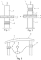
- the safety element 1 comprises a front crash box 2 in the direction of travel and a longitudinal profile 3 arranged behind it.
- the crash box 2 and the longitudinal profile 3 are firmly connected to one another via connection plates 4 (flanges).
- the longitudinal profile 3 is firmly anchored in the vehicle.
- compression or deformation and folding can occur in the area of the longitudinal profile 3.
- a shock wave transmitter 6 is arranged between the connection plates 4, which acts as a pulse wave modulator and causes an impedance jump through the choice of material.
- shock wave transmitter 6 is plastic-coated.
- the parts are attached to one another by means of a clamping screw connection.
- a connection using other methods would also be conceivable, e.g. Inert gas welding.
- the shock wave transmitter 6 can also influence how the deformation 5 or folding takes place, e.g. to get the preferred order of a fold and not a kink.
- Such a safety element 1 is arranged in a front bumper vehicle structure 10 on the left and right (in the direction of travel) behind a front, curved cross member 11.
- each security element 1 comprises a shock wave transmitter 16.
- this shock wave transmitter 16 consists of a piezoelectric material that can be adjusted in its reflection and transmission behavior by an applied voltage. This allows the impedance jump to be changed in a targeted manner.
- the respective shock wave transmitter 16 is connected to an on-board computer 17, which controls the applied voltage on the basis of the speed, for which purpose it is coupled to a corresponding speed sensor 18.
- the shock wave transmitter 16 can be trimmed to reflect, so that the crash box 2 is essentially deformed.
Landscapes
- Engineering & Computer Science (AREA)
- Mechanical Engineering (AREA)
- Chemical & Material Sciences (AREA)
- Combustion & Propulsion (AREA)
- Transportation (AREA)
- Vibration Dampers (AREA)
Description
- Die Erfindung betrifft ein Verfahren zur Einstellung der Deformation eines Sicherheitselements eines Fahrzeugs, insbesondere eines Kraftfahrzeugs, wobei das Sicherheitselement ein Crashelement und einem Längsträger aufweist, wobei das Crashelements in Aufprallrichtung vor dem Längsträger zur Aufnahme einer im wesentlichen axialen Aufprall-Kraft ausgestaltet ist, und ein entsprechendes Sicherheitselement.
- Der Einsatz von Sicherheitselementen sowie von Crashboxen oder allgemein Crashelementen bei Fahrzeugen, insbesondere Kraftfahrzeugen, ist bekannt.
- Bei einem Auffahrunfall wird durch Deformation von Werkstoffen innerhalb der Crashbox Bewegungsenergie abgebaut, um die Fahrzeuginsassen und den gesamten Aufbau einer geringeren Verzögerungskraft auszusetzen. Dadurch sollen unzulässige Deformationen am Aufbau (welche mitunter einen Totalschaden bedeuten können) und Verletzungen der Insassen verhindert werden. Crashboxen werden für Kollisionen bis zu einer bestimmten Aufprallgeschwindigkeit z. B. von 15 km/h ausgelegt. Sie können nach einem Unfall mit relativ geringen Kosten ausgetauscht werden.
- Die steigenden Sicherheitsanforderungen, insbesondere für den Frontal- und Seitenaufprall von Personenkraftwagen haben einen hohen Einfluss auf die Auslegung der Fahrzeugstruktur. Während des Aufpralls wird, wie beschrieben, die kinetische Energie des Fahrzeugs in Form von plastischer Deformation im Crashelement abgebaut.
Bei einem Frontalaufprall bestimmt der Beulablauf die Energieabsorption im Fahrzeug bzw. im Crashelement und somit die Sicherheit beim Aufprall. Um die Sicherheit von Fahrzeuginsassen zu gewährleisten, eine wirtschaftliche Reparatur zu ermöglichen und um ein wirtschaftliches Design zu erzielen ist es gewünscht diese Faltsequenz (Beulablauf) beeinflussen zu können. - Das Falten der Crashelemente in Fahrzeugen hängt von deren Geometrie, dem verwendeten Material und der Aufprallgeschwindigkeit ab. Um bei mehreren hintereinander geschalteten Strukturen die Faltsequenz zu beeinflussen, müssen die Crashelemente entsprechend so ausgelegt werden, dass das gewünschte Versagen bzw. die Faltsequenz zum gezielten Energieabbau auftreten kann. Um eine hohe Energieabsorption beim Aufprall im Fahrzeug und eine wirtschaftliche Reparatur zu ermöglichen soll das Crashelement bzw.
- die Crashbox sich als erstes bzw. vor dem Längsträger falten. Ein Verfahren nach dem Oberbegriff des Anspruchs 1 sowie ein Sicherheitselement nach dem Oberbegriff des Anspruchs 7 sind aus
DE19700022 A1 bekannt. - Aus der
DE 10 2007 012 962 B4 ist eine Sicherheitseinrichtung für ein Kraftfahrzeug bekannt, bei welchem zwischen einem Stoßfängerquerträger und einem Längsträger ein bei einem Anprall in den Längsträger hinein verlagerbares Deformationselement angeordnet ist, wobei dem Deformationselement ein Aktuator zugeordnet ist, der dafür vorgesehen ist, die Verlagerung des Deformationselements in den Längsträger hinein in einem festgelegten Geschwindigkeitsbereich freizugeben und bei Über- oder Unterschreiten des Geschwindigkeitsbereichs die Verlagerung des Deformationselements in den Längsträger hinein zu blockieren. Dazu ist das Deformationselement ein umstülpbarer Rohrkörper ist, dessen an dem Längsträger angeordnetes hinteres Ende kragenartig nach außen umgestülpt ist, wobei das umgestülpte, hintere Ende fest mit einem Widerlagerring verbunden ist, welcher von dem Aktuator gegenüber dem Längsträger blockierbar oder freigebbar ist. -
US 5,732,801 A offenbart ebenfalls ein rohrförmiges Deformationselement, bei dem das Rohr mit einem gestanzten Muster, das ein Knicken des Rohrs beim Zusammendrücken bestimmt. Eine Ausführungsform betrifft ein in axialer Richtung zweiteiliges Rohr, wobei zwischen den Teilen eine Membran ("diaphragm") angeordnet ist, um ein Ausbreiten der Rohraufweitung von einem Teil in das nächste zu verhindern. -
WO 2015/150656 A1 beschreibt eine Vorderstruktur eines Kraftfahrzeugs mit zwei Längsstrukturprofilen, zwei verformbare Profilabschnitten, Mittel zum Befestigen der verformbaren Profilabschnitte an den entsprechenden strukturellen Profilabschnitten und eine gekrümmte Querstrebe, die an den vorderen Enden der verformbaren Profilabschnitte befestigt ist. Die Mittel zum Befestigen eines der verformbaren Profilabschnitte an dem entsprechenden strukturellen Profilabschnitt sind so konfiguriert, dass sie eine Querbewegung des verformbaren Profilabschnitts in Richtung Außenseite des hinteren Endes relativ zu dem Strukturprofilabschnitt ermöglichen, so dass im Falle eines Aufpralls auf den gekrümmten Träger, eine seitliche Verformung des vorderen Endes des entsprechenden Strukturprofilabschnitts nach außen erzeugt wird. - Demgegenüber besteht die Aufgabe der vorliegenden Erfindung darin, ein Verfahren zur Einstellung der Deformation eines Crashelements eines Fahrzeugs und ein entsprechendes Crashelement bereitzustellen, bei dem die Reihenfolge der Deformation festlegbar ist.
- Diese Aufgabe wird durch das in Anspruch 1 wiedergegebene Verfahren bzw. das in Anspruch 7 angegebene Sicherheitselement gelöst. Vorteilhafte Ausgestaltungen ergeben sich aus den Unteransprüchen und der Beschreibung.
- Erfindungsgemäß ist erkannt worden, dass wenn zwischen Crashelement und Längsträger ein Schockwellentransmitter angeordnet wird, der je nach Ausgestaltung einen Anteil einer durch den Aufprall entstehenden Schockwelle in das Crashelement zurück reflektiert und einen anderen Anteil der Schockwelle in den Längsträger durchlässt, es möglich ist, das Deformationsverhalten des Sicherheitselements zu steuern. So kann die Reihenfolge der Deformation, d.h. z.B. Crashelement vor Längsträger, und das Faltverhalten des Crashelements und/oder des Längsträgers eingestellt werden.
- Mit Schockwellen sind vorliegend keine Wellen gemeint, die sich in einem Fluid ausbreiten, sondern Impulswellen, die sich in Folge eines starken Aufschlags innerhalb einer Struktur ausbreiten - analog zu Körperschall - wie dies auch in der
US 2018/0100519 A1 im Absatz [0004] beschrieben ist. - Bei dem Schockwellen-Transmitter handelt es sich im Wesentlichen um eine Umsetzung eines Impedanz-Sprunges durch nacheinander platzierte unterschiedliche Materialien, innerhalb derer die akustische Impedanz (Schallgeschwindigkeit x Dichte) unterschiedlich ist.
- An diesem Impedanz-Sprung werden die Schockwellen bzw. Impulswellen reflektiert oder durchgelassen. Die erfolgt in etwa analog zu beispielsweise Ultraschall-Körperschallwellen in der Ultraschalldiagnostik (siehe z.B. https://praktikum.physik.unibremen.de/fileadmin/Physika/Versuche/FortgeschrittenenPraktikum/Anleitung/fp12_Ultrasch all_02_12_08.pdf - Seite 2 "Reflexion und Transmission an Grenzflächen").
- Im Grunde ist der Schockwellentransmitter also ein Segment zur gezielten Reflexion/ Transmission der Impulswellen in einem Bauteil. Er ist also mit anderen Worten ein Impulswellenmodulator, der je nach Ausgestaltung die Wellen komplett reflektiert, komplett durchlässt oder teilweise reflektiert bzw. durchlässt.
- Durch Überlagerung einer vorhanden Impulswelle im Bauteil bzw. deren Reflexionen wird in einem Bereich des Bauteils eine kritische Belastung überschritten, die dann zum Beulen dieser Zone führt. Durch gezielte Auslegung und Wahl von Werkstoffen und Reflexions- bzw. Transmissionspunkte kann so gesteuert werden, welcher Bereich zuerst beult oder sich verformt.
- Ein wesentlicher Einflussfaktor bleibt jedoch auch die Geometrie des Bauteils.
In der Auslegung ist somit die Position des Transmitters (Modulators) zu beeinflussen und in welchem Maße dieses Bauteile Reflektiert bzw. Transmittiert. Mit einer Berechnung kann die Wellenausbreitung abgeschätzt werden und die Stelle, an welcher diese einen kritischen Wert zuerst erreicht abgeschätzt werden. - Dadurch kann wiederum die Fahrzeugstruktur so ausgelegt werden, dass sie an der gewünschten Stelle versagt (Sollbruchstelle). Dies ermöglicht es, einerseits die Sicherheit der Passgiere einzuhalten und andererseits eine wirtschaftliche Reparatur durchzuführen.
- Es ist sinnvoll, den durch den Schockwellentransmitter bewirkten Impedanz-Sprung genau einzustellen, um das Beulverhalten zu stabilisieren. Die Einstellmöglichkeiten werden durch die Wahl der Werkstoffe vorgegeben (Dichte/ E-Modul). Durch die gezielte Auslegung des Impedanz-Sprunges kann die Schädigung bzw. Deformation des Längsträgers oder Crashelement optimiert werden.
- Die Auslegung des Längsträgers kann nicht nur durch den Impedanz-Sprung reguliert werden, sondern auch durch die Länge der zwei Strukturen (Crashelement und Längsträger) und die Dicke der Platte (Schockwellentransmitter) zwischen den Strukturen. Je Länger das Crashelement oder der Längsträger, desto länger die Zeit bis zur Reflexion bzw. Transmission. So können z. B. Strukturen verschiedener Länge zum gewünschten Deformationsmuster führen.
- Wie oben dargestellt, ist es festgestellt worden, dass das Verhalten des Schockwellentransmitters sich auch durch eine geeignete Materialauswahl einstellen lässt. So kann der Betrag der Spannung, der transmittiert bzw. durchgelassen und reflektiert wird, gezielt beeinflusst bzw. vorgeben werden. Insbesondere kann die Materialauswahl auf der Dichte und/oder dem Elastizitätsmodul des Materials beruhen, da diese maßgeblich sind.
- Als Material für den Schockwellentransmitter sind insbesondere Stahl und Aluminium geeignet. Da dessen Verhalten im Wesentlichen von Dichte und E-Modul beeinflusst ist, spielt die konkrete Legierung eine untergeordnete Rolle.
Als Materialstärke kommt eine Dicke von etwa 0,5 bis 4 mm, insbesondere ca. 2 mm in Frage. - Auch der Einsatz von Hybridplatten aus z.B. Kunststoffbeschichteten Metallen ist möglich.
- Kontakt-Korrosion kann bei einer Stahl-/AI-Kombination z.B. durch Hybridplatten oder mit einer Beschichtung (E-coating) des Schockwellentransmitters verhindert werden.
- Zusätzlich ist festgestellt worden, dass es möglich ist, das Reflektions- bzw. Transmissionsverhalten des Materials des Schockwellentransmitters aktiv veränderbar auszugestalten.
- So kann für den Schockwellentransmitter ein Material ausgewählt werden, dessen Reflektions- bzw. Transmissionsverhalten, z.B. durch Veränderung der Dichte und/oder des Elastizitätsmoduls, durch eine Veränderung einer angelegten Spannung, eines äußeren Magnetfelds oder eines aufgebrachten Drucks auf Wunsch geändert werden kann.
- Das Material kann z.B. eine Formgedächtnislegierung, ein piezoelektrisches Polymer oder ein magnetorheologisches Material sein. Insbesondere kann ein Material ausgewählt werden, das aktiv in seiner Steifheit veränderbar ist.
- Bei einem so aktiv veränderbaren Material ist es sinnvoll, diese Eigenschaft mit der Aufprallgeschwindigkeit des Fahrzeugs zu verändern, um je nach Bereich der Aufprallgeschwindigkeit eine Änderung des Verhaltens des Schockwellentransmitters und somit des Sicherheitselements zu erreichen.
- Dazu können die Fahrzeugsensoren über eine Fahrzeugsteuerung, z.B. Bordcomputer, ECU etc, die Parameter gezielt ändern, z.B. den die anliegende Spannung am Schockwellentransmitter variieren.
- Der Schockwellentransmitter ist vorzugsweise zwischen Set-plate (Crashbox seitig) und Mounting-plate (Längsträger seitig) angebracht. Typischerweise ist die Verbindung geschraubt, da ein partieller Austausch des Crashmanagement-Systems vorgesehen ist.
- Ferner kann auch ein asymmetrischer Aufbau bezogen auf das Fahrzeug gewählt werden (linker Längsträger anders gestaltet als rechter Längsträger), die Längsträger Infolge der Motorlager meist nicht symmetrisch ausgeführt sind und daher andere Knicklasten aufweisen. Mit anderen Worten, es können unterschiedliche Schockwellentransmitter pro Längsträger bzw. Sicherheitselement verwendet werden.
- Weitere Details der Erfindung ergeben sich aus der nachfolgenden Beschreibung von Ausführungsbeispielen anhand der Zeichnung, in der
- Fig. 1
- eine schematische Seitenansicht eines klassischen Sicherheitselements in einem Fahrzeug;
- Fig. 2
- eine schematische Seitenansicht eines erfindungsgemäßen Sicherheitselements;
- Fig. 3
- eine schematische Ansicht einer vorderen Stoßfänger-Fahrzeugstruktur mit erfindungsgemäßen Sicherheitselementen.
- In den
Figuren 1 ist ein als Ganzes mit 1 bezeichnetes Sicherheitselement dargestellt. - Das Sicherheitselement 1 umfasst eine in Fahrrichtung vordere Crashbox 2 und ein dahinter angeordnetes Längsprofil 3. Die Crashbox 2 und das Längsprofil 3 sind über Anbindungsplatten 4 (Flansche) miteinander fest verbunden. Das Längsprofil 3 ist fest im Fahrzeug verankert.
- Wirkt nun eine im wesentlichen axiale Aufprallkraft F auf die Crashbox 2 ein, so wird die gesamte Struktur 1 gestaucht und es entsteht dabei eine Deformation 5.
- In dem dargestellten klassischen Beispiel kann es zur Stauchung bzw. Deformation und Faltung im Bereich des Längsprofils 3 kommen.
- Dies ist nicht erwünscht, da eigentlich gewünscht ist, dass die Crashbox 2 zuerst deformieren soll.
- Um dies zu unterstützen, ist erfindungsgemäß vorgesehen, dass zwischen den Anbindungsplatten 4 ein Schockwellentransmitter 6 angeordnet ist, der als Impulswellenmodulator wirkt und durch die Materialauswahl einen Impedanz-Sprung bewirkt.
- Dieser ist aus einem anderen Material, nämlich Aluminium mit einer Stärke von 2 mm hergestellt, als die Crashbox 2 bzw. das Längsprofil 3 aus Stahl hergestellt. Um eine Kontaktkorrosion zu verhindern, ist der Schockwellentransmitter 6 kunststoffbeschichtet.
- Vorliegend sind die Teile durch eine Klemm-Verschraubung miteinander befestigt. Denkbar wäre auch eine Verbindung durch andere Verfahren, wie z.B. Schutzgasschweißen.
- Der am Schockwellentransmitter 6 auftretende und gezielt eingestellte Impedanz-Sprung durch die unterschiedlichen Materialien der Crashbox 2, des Längsprofils 3 und des Schockwellentransmitters 6 selbst bewirkt, dass die durch die auf die Crashbox 2 einwirkende Aufprallkraft F erzeugten Schockwellen bzw. Impulswellen nur teilweise in das Längsprofil 3 durchgelassen wird und die Impulswellen so reflektiert werden, dass nun die Crashbox 2 eine Deformation 6 durchläuft, da dort eine kritische Belastung überschritten wird.
- Somit kann zusätzlich zu strukturellen Eigenschaften sichergestellt werden, dass tatsächlich die Crashbox wie gewollt zuerst deformiert, um Energie umzuwandeln.
- Auch kann durch den Schockwellentransmitter 6 beeinflusst werden, wie die Deformation 5 bzw. Faltung abläuft, um z.B. die bevorzugte Reihenfolge einer Faltung zu erhalten und nicht einen Knick.
- In der
Figur 3 ist ein solches Sicherheitselement 1 in einer vorderen Stoßfänger-Fahrzeugstruktur 10 jeweils links und rechts (in Fahrtrichtung) hinter einem vorderen, gebogenen Querträger 11 angeordnet. - Jedes Sicherheitselement 1 umfasst, wie oben dargestellt, eine Schockwellentransmitter 16.
- Im Unterschied zu soeben, besteht dieser Schockwellentransmitter 16 aus einem piezoelektrischen Material, das durch eine angelegte Spannung in seinem Reflektions- und Transmissionsverhalten einstellen lässt. Somit lässt sich der Impedanz-Sprung gezielt verändern.
- Dazu ist der jeweilige Schockwellentransmitter 16 an einen Bordcomputer 17 angeschlossen, der die angelegte Spannung anhand der Geschwindigkeit steuert, wozu dieser mit entsprechender Geschwindigkeitssensorik 18 gekoppelt ist.
- So kann bei niedrigen Geschwindigkeiten der Schockwellentransmitter 16 auf Reflektion getrimmt werden, sodass im Wesentlichen die Crashbox 2 deformiert wird.
Claims (10)
- Verfahren zur Einstellung der Deformation eines Sicherheitselements (1) eines Kraftfahrzeugs, wobei das Sicherheitselement (1) ein Crashelement (2) und einen Längsträger (3) aufweist, wobei das Crashelement (2) in Aufprallrichtung vor dem Längsträger (3) zur Aufnahme einer im wesentlichen axialen Aufprall-Kraft (F) angeordnet und ausgestaltet ist, dadurch gekennzeichnet, dass zwischen Crashelement (2) und Längsträger (3) ein Schockwellentransmitter (6) angeordnet wird, bei dem es sich im Wesentlichen um ein Segment zur gezielten Reflexion oder Transmission der Impulswellen in einem Bauteil durch eine Umsetzung eines Impedanz-Sprunges durch nacheinander platzierte unterschiedliche Materialien handelt, innerhalb derer die akustische Impedanz unterschiedlich ist, so dass je nach Ausgestaltung ein Anteil einer durch den Aufprall entstehenden Schockwelle bzw. Impulswelle in das Crashelement (2) zurück reflektiert und einen anderen Anteil der Schockwelle bzw. Impulswelle in den Längsträger (3) durchgelassen wird.
- Verfahren nach Anspruch 1, dadurch gekennzeichnet, dass der am Schockwellentransmitter (6) auftretende Impedanz-Sprung durch eine geeignete Materialauswahl des Crashelements (2), des Längsträgers (3) und des Schockwellentransmitters (6) selbst eingestellt wird.
- Verfahren nach Anspruch 2, dadurch gekennzeichnet, dass die Materialauswahl des Schockwellentransmitters (6) auf der Dichte und/oder dem Elastizitätsmodul des Materials beruht.
- Verfahren nach Anspruch 2 oder 3, dadurch gekennzeichnet, dass das Reflektions- bzw. Transmissionsverhalten des Materials des Schockwellentransmitters (6) aktiv veränderbar ist.
- Verfahren nach Anspruch 4, dadurch gekennzeichnet, dass Material ein aktiv veränderbares Material ist, wie eine Formgedächtnislegierung, ein piezoelektrisches Polymer oder ein magnetorheologisches Material ist, das aktiv in seiner Steifheit veränderbar ist.
- Verfahren nach Anspruch 4 oder 5, dass das Reflektions- und Transmissionsverhalten des Materials anhand der Geschwindigkeit des Fahrzeugs beim Aufprall aktiv eingestellt wird bzw. veränderbar ist.
- Sicherheitselement (1) eines Kraftfahrzeugs, wobei das Sicherheitselement (1) ein Crashelement (2) und einen Längsträger (3) aufweist, wobei das Crashelement (2) in Aufprallrichtung vor dem Längsträger (3) zur Aufnahme einer im wesentlichen axialen Aufprall-Kraft (F) angeordnet und ausgestaltet ist, dadurch gekennzeichnet, dass zwischen Crashelement (2) und Längsträger (3) ein Schockwellentransmitter (6) angeordnet ist, bei dem es sich im Wesentlichen um ein Segment zur gezielten Reflexion oder Transmission der Impulswellen in einem Bauteil durch eine Umsetzung eines Impedanz-Sprunges durch nacheinander platzierte unterschiedliche Materialien handelt, innerhalb derer die akustische Impedanz unterschiedlich ist, wobei der am Schockwellentransmitter (6) auftretende Impedanz-Sprung durch eine geeignete Materialauswahl des Crashelements (2), des Längsträgers (3) und des Schockwellentransmitters (6) selbst eingestellt wird.
- Sicherheitselement nach Anspruch 7, dadurch gekennzeichnet, dass das Material des Schockwellentransmitters (6) ein aktives Verändern des Reflektions- und Transmissionsverhaltens erlaubt.
- Sicherheitselement nach Anspruch 8, dadurch gekennzeichnet, dass das Material eine Formgedächtnislegierung, ein piezoelektrisches Polymer oder ein magnetorheologisches Material ist, das aktiv in seiner Steifheit veränderbar ist.
- Sicherheitselement nach Anspruch 8 oder 9, dass das Reflektions- und Transmissionsverhalten des Materials anhand der über Geschwindigkeitssensoren des Fahrzeugs beim Aufprall eingestellt wird, wozu der Schockwellentransmitter (6) mit einer Fahrzeugsteuerung (17) verbunden ist.
Applications Claiming Priority (1)
| Application Number | Priority Date | Filing Date | Title |
|---|---|---|---|
| DE102018208723.7A DE102018208723A1 (de) | 2018-06-04 | 2018-06-04 | Verfahren zur Einstellung der Deformation eines Sicherheitselements eines Fahrzeugs und ein entsprechendes Sicherheitselement |
Publications (2)
| Publication Number | Publication Date |
|---|---|
| EP3578424A1 EP3578424A1 (de) | 2019-12-11 |
| EP3578424B1 true EP3578424B1 (de) | 2020-11-11 |
Family
ID=66751956
Family Applications (1)
| Application Number | Title | Priority Date | Filing Date |
|---|---|---|---|
| EP19178030.3A Active EP3578424B1 (de) | 2018-06-04 | 2019-06-04 | Verfahren zur einstellung der deformation eines sicherheitselements eines fahrzeugs und ein entsprechendes sicherheitselement |
Country Status (3)
| Country | Link |
|---|---|
| EP (1) | EP3578424B1 (de) |
| CN (1) | CN110549973A (de) |
| DE (1) | DE102018208723A1 (de) |
Families Citing this family (1)
| Publication number | Priority date | Publication date | Assignee | Title |
|---|---|---|---|---|
| TR2023012622A2 (tr) * | 2023-10-06 | 2025-04-21 | Oyak Renault Otomobil Fabrikalari Anonim Sirketi | Akilli çarpişma yöneti̇m yöntemi̇ ve si̇stemi̇ |
Family Cites Families (9)
| Publication number | Priority date | Publication date | Assignee | Title |
|---|---|---|---|---|
| US5732801A (en) | 1996-08-05 | 1998-03-31 | Gertz; David C. | Energy absorbing bumper support structure |
| DE19700022A1 (de) * | 1997-01-02 | 1998-07-09 | Wilfried Ball | Stoßfängeranordnung für Kraftfahrzeuge |
| US7029044B2 (en) * | 2003-11-18 | 2006-04-18 | General Motors Corporation | Tunable, healable vehicle impact devices |
| US20050202248A1 (en) * | 2004-03-12 | 2005-09-15 | Browne Alan L. | Morphable body moldings, rub strips, and bumpers |
| DE102005039467B3 (de) * | 2005-08-20 | 2007-03-01 | Hbpo Gmbh | Flanschverbindung zur Verschraubung einer Crashbox und eines Montageträgers mit einem Fahrzeuglängsträger |
| DE102007012962B4 (de) | 2007-03-14 | 2013-09-05 | Benteler Automobiltechnik Gmbh | Sicherheitseinrichtung für ein Kraftfahrzeug |
| FR3019516B1 (fr) | 2014-04-04 | 2016-04-15 | Peugeot Citroen Automobiles Sa | Vehicule automobile avec crashbox a rupture programmee en cas d'impact avant. |
| US9371048B2 (en) * | 2014-06-23 | 2016-06-21 | Ford Global Technologies, Llc | Energy absorbing member for a bumper assembly of a vehicle |
| US11002294B2 (en) | 2016-10-07 | 2021-05-11 | General Electric Comany | Impact force dispersal assembly for turbine engines and methods of fabricating the same |
-
2018
- 2018-06-04 DE DE102018208723.7A patent/DE102018208723A1/de not_active Ceased
-
2019
- 2019-05-30 CN CN201910462547.6A patent/CN110549973A/zh active Pending
- 2019-06-04 EP EP19178030.3A patent/EP3578424B1/de active Active
Non-Patent Citations (1)
| Title |
|---|
| None * |
Also Published As
| Publication number | Publication date |
|---|---|
| EP3578424A1 (de) | 2019-12-11 |
| DE102018208723A1 (de) | 2019-12-05 |
| CN110549973A (zh) | 2019-12-10 |
Similar Documents
| Publication | Publication Date | Title |
|---|---|---|
| DE102004036929B4 (de) | Pralldämpferanordnung für ein Kraftfahrzeug | |
| EP1625978B1 (de) | Crashbox | |
| EP2480432B1 (de) | Vorrichtung und verfahren zum adaptiven abbau von crashenergie | |
| EP1990251B1 (de) | Energieverzehreinrichtung für mehrgliedrige Fahrzeuge | |
| DE102016201008A1 (de) | Stoßfängereinheit für ein Kraftfahrzeug | |
| DE2825460A1 (de) | Energieabsorber, insbesondere fuer motorfahrzeuge | |
| DE102013001585B4 (de) | Stoßfängeranordnung | |
| EP2692589B1 (de) | Stoßfängeranordnung mit verminderten Bauraum | |
| DE102010054641A1 (de) | Stoßfängeranordnung sowie Verfahren zum Betreiben einer Stoßfängeranordnung in einen Crashfall | |
| EP3459828B1 (de) | Vorrichtung zur übertragung von kräften im crashfall eines kraftfahrzeugs | |
| DE102008009964A1 (de) | Kollision-Detektorvorrichtung und Schutzsystem | |
| EP0850807A2 (de) | Stossverzehrvorrichtung für ein Kraftfahrzeug | |
| DE102011078029B3 (de) | Vorrichtung und Verfahren zum Verändern einer Steifigkeit eines Querträgers eines Fahrzeugs | |
| DE2460598A1 (de) | Stossdaempfungsvorrichtung | |
| DE102013000391B4 (de) | Deformationselement für ein Fahrzeug und Fahrzeug mit einem derartigen Deformationselement | |
| DE102008060716A1 (de) | Crashbox | |
| DE102018008894A1 (de) | Energieabsorptions-Baueinheit für einen Kraftwagen sowie Energieabsorptionselement und Verstärkungselement hierfür | |
| DE102004034577A1 (de) | Vorrichtung zur Absorption von Aufprallenergie an einem Kraftfahrzeug | |
| EP3578424B1 (de) | Verfahren zur einstellung der deformation eines sicherheitselements eines fahrzeugs und ein entsprechendes sicherheitselement | |
| DE10358492A1 (de) | Crashelement in Form eines Hohlprofils | |
| DE102008045515B4 (de) | Vorrichtung zur Stoßenergieaufnahme durch plastische Verformung für Kraftfahrzeuge | |
| DE102017211339B4 (de) | Bremskraftverstärkereinrichtung mit einem verformbaren Aktuator | |
| DE102013000481A1 (de) | Deformationselement für ein Fahrzeug und Fahrzeug mit einem derartigen Deformationselement | |
| DE102013000459B3 (de) | Deformationselement für ein Fahrzeug und Fahrzeug mit einem derartigen Deformationselement | |
| DE102010031358A1 (de) | Crashstruktur zur Aufnahme von Crashenergie und Verfahren zur Einstellung einer Steifigkeit einer Crashstruktur |
Legal Events
| Date | Code | Title | Description |
|---|---|---|---|
| PUAI | Public reference made under article 153(3) epc to a published international application that has entered the european phase |
Free format text: ORIGINAL CODE: 0009012 |
|
| STAA | Information on the status of an ep patent application or granted ep patent |
Free format text: STATUS: THE APPLICATION HAS BEEN PUBLISHED |
|
| AK | Designated contracting states |
Kind code of ref document: A1 Designated state(s): AL AT BE BG CH CY CZ DE DK EE ES FI FR GB GR HR HU IE IS IT LI LT LU LV MC MK MT NL NO PL PT RO RS SE SI SK SM TR |
|
| AX | Request for extension of the european patent |
Extension state: BA ME |
|
| STAA | Information on the status of an ep patent application or granted ep patent |
Free format text: STATUS: REQUEST FOR EXAMINATION WAS MADE |
|
| 17P | Request for examination filed |
Effective date: 20200612 |
|
| RBV | Designated contracting states (corrected) |
Designated state(s): AL AT BE BG CH CY CZ DE DK EE ES FI FR GB GR HR HU IE IS IT LI LT LU LV MC MK MT NL NO PL PT RO RS SE SI SK SM TR |
|
| GRAP | Despatch of communication of intention to grant a patent |
Free format text: ORIGINAL CODE: EPIDOSNIGR1 |
|
| STAA | Information on the status of an ep patent application or granted ep patent |
Free format text: STATUS: GRANT OF PATENT IS INTENDED |
|
| RIC1 | Information provided on ipc code assigned before grant |
Ipc: B60R 19/36 20060101ALI20200701BHEP Ipc: B62D 21/15 20060101ALI20200701BHEP Ipc: B60R 19/34 20060101ALI20200701BHEP Ipc: B60R 19/26 20060101AFI20200701BHEP |
|
| INTG | Intention to grant announced |
Effective date: 20200724 |
|
| RIN1 | Information on inventor provided before grant (corrected) |
Inventor name: BACH, ALEKSANDAR Inventor name: JAFARZADEH AGHDAM, NIMA Inventor name: SCHROEDER, KAI-UWE Inventor name: PASLIGH, NIELS Inventor name: LYSSAKOW, PAWEL |
|
| GRAS | Grant fee paid |
Free format text: ORIGINAL CODE: EPIDOSNIGR3 |
|
| GRAA | (expected) grant |
Free format text: ORIGINAL CODE: 0009210 |
|
| STAA | Information on the status of an ep patent application or granted ep patent |
Free format text: STATUS: THE PATENT HAS BEEN GRANTED |
|
| AK | Designated contracting states |
Kind code of ref document: B1 Designated state(s): AL AT BE BG CH CY CZ DE DK EE ES FI FR GB GR HR HU IE IS IT LI LT LU LV MC MK MT NL NO PL PT RO RS SE SI SK SM TR |
|
| REG | Reference to a national code |
Ref country code: GB Ref legal event code: FG4D Free format text: NOT ENGLISH |
|
| REG | Reference to a national code |
Ref country code: CH Ref legal event code: EP |
|
| REG | Reference to a national code |
Ref country code: AT Ref legal event code: REF Ref document number: 1333157 Country of ref document: AT Kind code of ref document: T Effective date: 20201115 |
|
| REG | Reference to a national code |
Ref country code: DE Ref legal event code: R096 Ref document number: 502019000390 Country of ref document: DE |
|
| REG | Reference to a national code |
Ref country code: IE Ref legal event code: FG4D Free format text: LANGUAGE OF EP DOCUMENT: GERMAN |
|
| REG | Reference to a national code |
Ref country code: NL Ref legal event code: MP Effective date: 20201111 |
|
| PG25 | Lapsed in a contracting state [announced via postgrant information from national office to epo] |
Ref country code: PT Free format text: LAPSE BECAUSE OF FAILURE TO SUBMIT A TRANSLATION OF THE DESCRIPTION OR TO PAY THE FEE WITHIN THE PRESCRIBED TIME-LIMIT Effective date: 20210311 Ref country code: RS Free format text: LAPSE BECAUSE OF FAILURE TO SUBMIT A TRANSLATION OF THE DESCRIPTION OR TO PAY THE FEE WITHIN THE PRESCRIBED TIME-LIMIT Effective date: 20201111 Ref country code: FI Free format text: LAPSE BECAUSE OF FAILURE TO SUBMIT A TRANSLATION OF THE DESCRIPTION OR TO PAY THE FEE WITHIN THE PRESCRIBED TIME-LIMIT Effective date: 20201111 Ref country code: NO Free format text: LAPSE BECAUSE OF FAILURE TO SUBMIT A TRANSLATION OF THE DESCRIPTION OR TO PAY THE FEE WITHIN THE PRESCRIBED TIME-LIMIT Effective date: 20210211 Ref country code: GR Free format text: LAPSE BECAUSE OF FAILURE TO SUBMIT A TRANSLATION OF THE DESCRIPTION OR TO PAY THE FEE WITHIN THE PRESCRIBED TIME-LIMIT Effective date: 20210212 |
|
| PG25 | Lapsed in a contracting state [announced via postgrant information from national office to epo] |
Ref country code: LV Free format text: LAPSE BECAUSE OF FAILURE TO SUBMIT A TRANSLATION OF THE DESCRIPTION OR TO PAY THE FEE WITHIN THE PRESCRIBED TIME-LIMIT Effective date: 20201111 Ref country code: IS Free format text: LAPSE BECAUSE OF FAILURE TO SUBMIT A TRANSLATION OF THE DESCRIPTION OR TO PAY THE FEE WITHIN THE PRESCRIBED TIME-LIMIT Effective date: 20210311 Ref country code: PL Free format text: LAPSE BECAUSE OF FAILURE TO SUBMIT A TRANSLATION OF THE DESCRIPTION OR TO PAY THE FEE WITHIN THE PRESCRIBED TIME-LIMIT Effective date: 20201111 Ref country code: SE Free format text: LAPSE BECAUSE OF FAILURE TO SUBMIT A TRANSLATION OF THE DESCRIPTION OR TO PAY THE FEE WITHIN THE PRESCRIBED TIME-LIMIT Effective date: 20201111 Ref country code: BG Free format text: LAPSE BECAUSE OF FAILURE TO SUBMIT A TRANSLATION OF THE DESCRIPTION OR TO PAY THE FEE WITHIN THE PRESCRIBED TIME-LIMIT Effective date: 20210211 |
|
| REG | Reference to a national code |
Ref country code: LT Ref legal event code: MG9D |
|
| PG25 | Lapsed in a contracting state [announced via postgrant information from national office to epo] |
Ref country code: HR Free format text: LAPSE BECAUSE OF FAILURE TO SUBMIT A TRANSLATION OF THE DESCRIPTION OR TO PAY THE FEE WITHIN THE PRESCRIBED TIME-LIMIT Effective date: 20201111 |
|
| PG25 | Lapsed in a contracting state [announced via postgrant information from national office to epo] |
Ref country code: RO Free format text: LAPSE BECAUSE OF FAILURE TO SUBMIT A TRANSLATION OF THE DESCRIPTION OR TO PAY THE FEE WITHIN THE PRESCRIBED TIME-LIMIT Effective date: 20201111 Ref country code: LT Free format text: LAPSE BECAUSE OF FAILURE TO SUBMIT A TRANSLATION OF THE DESCRIPTION OR TO PAY THE FEE WITHIN THE PRESCRIBED TIME-LIMIT Effective date: 20201111 Ref country code: EE Free format text: LAPSE BECAUSE OF FAILURE TO SUBMIT A TRANSLATION OF THE DESCRIPTION OR TO PAY THE FEE WITHIN THE PRESCRIBED TIME-LIMIT Effective date: 20201111 Ref country code: SM Free format text: LAPSE BECAUSE OF FAILURE TO SUBMIT A TRANSLATION OF THE DESCRIPTION OR TO PAY THE FEE WITHIN THE PRESCRIBED TIME-LIMIT Effective date: 20201111 Ref country code: SK Free format text: LAPSE BECAUSE OF FAILURE TO SUBMIT A TRANSLATION OF THE DESCRIPTION OR TO PAY THE FEE WITHIN THE PRESCRIBED TIME-LIMIT Effective date: 20201111 Ref country code: CZ Free format text: LAPSE BECAUSE OF FAILURE TO SUBMIT A TRANSLATION OF THE DESCRIPTION OR TO PAY THE FEE WITHIN THE PRESCRIBED TIME-LIMIT Effective date: 20201111 |
|
| REG | Reference to a national code |
Ref country code: DE Ref legal event code: R097 Ref document number: 502019000390 Country of ref document: DE |
|
| PG25 | Lapsed in a contracting state [announced via postgrant information from national office to epo] |
Ref country code: DK Free format text: LAPSE BECAUSE OF FAILURE TO SUBMIT A TRANSLATION OF THE DESCRIPTION OR TO PAY THE FEE WITHIN THE PRESCRIBED TIME-LIMIT Effective date: 20201111 |
|
| PLBE | No opposition filed within time limit |
Free format text: ORIGINAL CODE: 0009261 |
|
| STAA | Information on the status of an ep patent application or granted ep patent |
Free format text: STATUS: NO OPPOSITION FILED WITHIN TIME LIMIT |
|
| 26N | No opposition filed |
Effective date: 20210812 |
|
| PG25 | Lapsed in a contracting state [announced via postgrant information from national office to epo] |
Ref country code: NL Free format text: LAPSE BECAUSE OF FAILURE TO SUBMIT A TRANSLATION OF THE DESCRIPTION OR TO PAY THE FEE WITHIN THE PRESCRIBED TIME-LIMIT Effective date: 20201111 Ref country code: AL Free format text: LAPSE BECAUSE OF FAILURE TO SUBMIT A TRANSLATION OF THE DESCRIPTION OR TO PAY THE FEE WITHIN THE PRESCRIBED TIME-LIMIT Effective date: 20201111 Ref country code: IT Free format text: LAPSE BECAUSE OF FAILURE TO SUBMIT A TRANSLATION OF THE DESCRIPTION OR TO PAY THE FEE WITHIN THE PRESCRIBED TIME-LIMIT Effective date: 20201111 |
|
| PG25 | Lapsed in a contracting state [announced via postgrant information from national office to epo] |
Ref country code: SI Free format text: LAPSE BECAUSE OF FAILURE TO SUBMIT A TRANSLATION OF THE DESCRIPTION OR TO PAY THE FEE WITHIN THE PRESCRIBED TIME-LIMIT Effective date: 20201111 |
|
| PG25 | Lapsed in a contracting state [announced via postgrant information from national office to epo] |
Ref country code: ES Free format text: LAPSE BECAUSE OF FAILURE TO SUBMIT A TRANSLATION OF THE DESCRIPTION OR TO PAY THE FEE WITHIN THE PRESCRIBED TIME-LIMIT Effective date: 20201111 Ref country code: MC Free format text: LAPSE BECAUSE OF FAILURE TO SUBMIT A TRANSLATION OF THE DESCRIPTION OR TO PAY THE FEE WITHIN THE PRESCRIBED TIME-LIMIT Effective date: 20201111 |
|
| REG | Reference to a national code |
Ref country code: BE Ref legal event code: MM Effective date: 20210630 |
|
| PG25 | Lapsed in a contracting state [announced via postgrant information from national office to epo] |
Ref country code: LU Free format text: LAPSE BECAUSE OF NON-PAYMENT OF DUE FEES Effective date: 20210604 |
|
| PG25 | Lapsed in a contracting state [announced via postgrant information from national office to epo] |
Ref country code: IE Free format text: LAPSE BECAUSE OF NON-PAYMENT OF DUE FEES Effective date: 20210604 |
|
| PG25 | Lapsed in a contracting state [announced via postgrant information from national office to epo] |
Ref country code: IS Free format text: LAPSE BECAUSE OF FAILURE TO SUBMIT A TRANSLATION OF THE DESCRIPTION OR TO PAY THE FEE WITHIN THE PRESCRIBED TIME-LIMIT Effective date: 20210311 |
|
| PG25 | Lapsed in a contracting state [announced via postgrant information from national office to epo] |
Ref country code: BE Free format text: LAPSE BECAUSE OF NON-PAYMENT OF DUE FEES Effective date: 20210630 |
|
| REG | Reference to a national code |
Ref country code: CH Ref legal event code: PL |
|
| PG25 | Lapsed in a contracting state [announced via postgrant information from national office to epo] |
Ref country code: LI Free format text: LAPSE BECAUSE OF NON-PAYMENT OF DUE FEES Effective date: 20220630 Ref country code: CH Free format text: LAPSE BECAUSE OF NON-PAYMENT OF DUE FEES Effective date: 20220630 |
|
| PG25 | Lapsed in a contracting state [announced via postgrant information from national office to epo] |
Ref country code: CY Free format text: LAPSE BECAUSE OF FAILURE TO SUBMIT A TRANSLATION OF THE DESCRIPTION OR TO PAY THE FEE WITHIN THE PRESCRIBED TIME-LIMIT Effective date: 20201111 |
|
| P01 | Opt-out of the competence of the unified patent court (upc) registered |
Effective date: 20230620 |
|
| PG25 | Lapsed in a contracting state [announced via postgrant information from national office to epo] |
Ref country code: HU Free format text: LAPSE BECAUSE OF FAILURE TO SUBMIT A TRANSLATION OF THE DESCRIPTION OR TO PAY THE FEE WITHIN THE PRESCRIBED TIME-LIMIT; INVALID AB INITIO Effective date: 20190604 |
|
| PG25 | Lapsed in a contracting state [announced via postgrant information from national office to epo] |
Ref country code: MK Free format text: LAPSE BECAUSE OF FAILURE TO SUBMIT A TRANSLATION OF THE DESCRIPTION OR TO PAY THE FEE WITHIN THE PRESCRIBED TIME-LIMIT Effective date: 20201111 |
|
| PG25 | Lapsed in a contracting state [announced via postgrant information from national office to epo] |
Ref country code: MT Free format text: LAPSE BECAUSE OF FAILURE TO SUBMIT A TRANSLATION OF THE DESCRIPTION OR TO PAY THE FEE WITHIN THE PRESCRIBED TIME-LIMIT Effective date: 20201111 |
|
| PGFP | Annual fee paid to national office [announced via postgrant information from national office to epo] |
Ref country code: DE Payment date: 20250509 Year of fee payment: 7 |
|
| PGFP | Annual fee paid to national office [announced via postgrant information from national office to epo] |
Ref country code: GB Payment date: 20250508 Year of fee payment: 7 |
|
| PGFP | Annual fee paid to national office [announced via postgrant information from national office to epo] |
Ref country code: FR Payment date: 20250512 Year of fee payment: 7 |
|
| REG | Reference to a national code |
Ref country code: AT Ref legal event code: MM01 Ref document number: 1333157 Country of ref document: AT Kind code of ref document: T Effective date: 20240604 |
|
| PG25 | Lapsed in a contracting state [announced via postgrant information from national office to epo] |
Ref country code: AT Free format text: LAPSE BECAUSE OF NON-PAYMENT OF DUE FEES Effective date: 20240604 |
|
| PG25 | Lapsed in a contracting state [announced via postgrant information from national office to epo] |
Ref country code: TR Free format text: LAPSE BECAUSE OF FAILURE TO SUBMIT A TRANSLATION OF THE DESCRIPTION OR TO PAY THE FEE WITHIN THE PRESCRIBED TIME-LIMIT Effective date: 20201111 |
|
| PGFP | Annual fee paid to national office [announced via postgrant information from national office to epo] |
Ref country code: AT Payment date: 20260410 Year of fee payment: 5 |