EP3578409A1 - Work vehicle power regeneration system - Google Patents
Work vehicle power regeneration system Download PDFInfo
- Publication number
- EP3578409A1 EP3578409A1 EP18906888.5A EP18906888A EP3578409A1 EP 3578409 A1 EP3578409 A1 EP 3578409A1 EP 18906888 A EP18906888 A EP 18906888A EP 3578409 A1 EP3578409 A1 EP 3578409A1
- Authority
- EP
- European Patent Office
- Prior art keywords
- voltage
- traveling motor
- traveling
- electric circuit
- rotational speed
- Prior art date
- Legal status (The legal status is an assumption and is not a legal conclusion. Google has not performed a legal analysis and makes no representation as to the accuracy of the status listed.)
- Granted
Links
- 230000008929 regeneration Effects 0.000 title claims abstract description 24
- 238000011069 regeneration method Methods 0.000 title claims abstract description 24
- 230000001172 regenerating effect Effects 0.000 claims abstract description 10
- 238000010248 power generation Methods 0.000 claims description 31
- 230000008859 change Effects 0.000 claims description 6
- 238000000034 method Methods 0.000 description 37
- 230000008569 process Effects 0.000 description 13
- 230000014509 gene expression Effects 0.000 description 12
- 238000010586 diagram Methods 0.000 description 8
- 230000004048 modification Effects 0.000 description 6
- 238000012986 modification Methods 0.000 description 6
- 230000009467 reduction Effects 0.000 description 6
- 230000001133 acceleration Effects 0.000 description 3
- 230000006870 function Effects 0.000 description 3
- 230000004913 activation Effects 0.000 description 2
- 239000003990 capacitor Substances 0.000 description 2
- 238000006243 chemical reaction Methods 0.000 description 2
- 230000007423 decrease Effects 0.000 description 2
- 230000000694 effects Effects 0.000 description 2
- 239000000446 fuel Substances 0.000 description 2
- 238000009499 grossing Methods 0.000 description 2
- 230000020169 heat generation Effects 0.000 description 2
- 230000002441 reversible effect Effects 0.000 description 2
- 230000008602 contraction Effects 0.000 description 1
- 238000001816 cooling Methods 0.000 description 1
- 230000003111 delayed effect Effects 0.000 description 1
- 230000000994 depressogenic effect Effects 0.000 description 1
- 238000001514 detection method Methods 0.000 description 1
- 230000003028 elevating effect Effects 0.000 description 1
- 239000002828 fuel tank Substances 0.000 description 1
- 239000010720 hydraulic oil Substances 0.000 description 1
- 230000002401 inhibitory effect Effects 0.000 description 1
- 230000004043 responsiveness Effects 0.000 description 1
- 239000004065 semiconductor Substances 0.000 description 1
- 239000002689 soil Substances 0.000 description 1
Images


Classifications
-
- B—PERFORMING OPERATIONS; TRANSPORTING
- B60—VEHICLES IN GENERAL
- B60W—CONJOINT CONTROL OF VEHICLE SUB-UNITS OF DIFFERENT TYPE OR DIFFERENT FUNCTION; CONTROL SYSTEMS SPECIALLY ADAPTED FOR HYBRID VEHICLES; ROAD VEHICLE DRIVE CONTROL SYSTEMS FOR PURPOSES NOT RELATED TO THE CONTROL OF A PARTICULAR SUB-UNIT
- B60W20/00—Control systems specially adapted for hybrid vehicles
-
- B—PERFORMING OPERATIONS; TRANSPORTING
- B60—VEHICLES IN GENERAL
- B60L—PROPULSION OF ELECTRICALLY-PROPELLED VEHICLES; SUPPLYING ELECTRIC POWER FOR AUXILIARY EQUIPMENT OF ELECTRICALLY-PROPELLED VEHICLES; ELECTRODYNAMIC BRAKE SYSTEMS FOR VEHICLES IN GENERAL; MAGNETIC SUSPENSION OR LEVITATION FOR VEHICLES; MONITORING OPERATING VARIABLES OF ELECTRICALLY-PROPELLED VEHICLES; ELECTRIC SAFETY DEVICES FOR ELECTRICALLY-PROPELLED VEHICLES
- B60L7/00—Electrodynamic brake systems for vehicles in general
- B60L7/10—Dynamic electric regenerative braking
- B60L7/12—Dynamic electric regenerative braking for vehicles propelled by dc motors
-
- B—PERFORMING OPERATIONS; TRANSPORTING
- B60—VEHICLES IN GENERAL
- B60K—ARRANGEMENT OR MOUNTING OF PROPULSION UNITS OR OF TRANSMISSIONS IN VEHICLES; ARRANGEMENT OR MOUNTING OF PLURAL DIVERSE PRIME-MOVERS IN VEHICLES; AUXILIARY DRIVES FOR VEHICLES; INSTRUMENTATION OR DASHBOARDS FOR VEHICLES; ARRANGEMENTS IN CONNECTION WITH COOLING, AIR INTAKE, GAS EXHAUST OR FUEL SUPPLY OF PROPULSION UNITS IN VEHICLES
- B60K6/00—Arrangement or mounting of plural diverse prime-movers for mutual or common propulsion, e.g. hybrid propulsion systems comprising electric motors and internal combustion engines ; Control systems therefor, i.e. systems controlling two or more prime movers, or controlling one of these prime movers and any of the transmission, drive or drive units Informative references: mechanical gearings with secondary electric drive F16H3/72; arrangements for handling mechanical energy structurally associated with the dynamo-electric machine H02K7/00; machines comprising structurally interrelated motor and generator parts H02K51/00; dynamo-electric machines not otherwise provided for in H02K see H02K99/00
- B60K6/20—Arrangement or mounting of plural diverse prime-movers for mutual or common propulsion, e.g. hybrid propulsion systems comprising electric motors and internal combustion engines ; Control systems therefor, i.e. systems controlling two or more prime movers, or controlling one of these prime movers and any of the transmission, drive or drive units Informative references: mechanical gearings with secondary electric drive F16H3/72; arrangements for handling mechanical energy structurally associated with the dynamo-electric machine H02K7/00; machines comprising structurally interrelated motor and generator parts H02K51/00; dynamo-electric machines not otherwise provided for in H02K see H02K99/00 the prime-movers consisting of electric motors and internal combustion engines, e.g. HEVs
- B60K6/42—Arrangement or mounting of plural diverse prime-movers for mutual or common propulsion, e.g. hybrid propulsion systems comprising electric motors and internal combustion engines ; Control systems therefor, i.e. systems controlling two or more prime movers, or controlling one of these prime movers and any of the transmission, drive or drive units Informative references: mechanical gearings with secondary electric drive F16H3/72; arrangements for handling mechanical energy structurally associated with the dynamo-electric machine H02K7/00; machines comprising structurally interrelated motor and generator parts H02K51/00; dynamo-electric machines not otherwise provided for in H02K see H02K99/00 the prime-movers consisting of electric motors and internal combustion engines, e.g. HEVs characterised by the architecture of the hybrid electric vehicle
- B60K6/46—Series type
-
- B—PERFORMING OPERATIONS; TRANSPORTING
- B60—VEHICLES IN GENERAL
- B60L—PROPULSION OF ELECTRICALLY-PROPELLED VEHICLES; SUPPLYING ELECTRIC POWER FOR AUXILIARY EQUIPMENT OF ELECTRICALLY-PROPELLED VEHICLES; ELECTRODYNAMIC BRAKE SYSTEMS FOR VEHICLES IN GENERAL; MAGNETIC SUSPENSION OR LEVITATION FOR VEHICLES; MONITORING OPERATING VARIABLES OF ELECTRICALLY-PROPELLED VEHICLES; ELECTRIC SAFETY DEVICES FOR ELECTRICALLY-PROPELLED VEHICLES
- B60L1/00—Supplying electric power to auxiliary equipment of vehicles
-
- B—PERFORMING OPERATIONS; TRANSPORTING
- B60—VEHICLES IN GENERAL
- B60L—PROPULSION OF ELECTRICALLY-PROPELLED VEHICLES; SUPPLYING ELECTRIC POWER FOR AUXILIARY EQUIPMENT OF ELECTRICALLY-PROPELLED VEHICLES; ELECTRODYNAMIC BRAKE SYSTEMS FOR VEHICLES IN GENERAL; MAGNETIC SUSPENSION OR LEVITATION FOR VEHICLES; MONITORING OPERATING VARIABLES OF ELECTRICALLY-PROPELLED VEHICLES; ELECTRIC SAFETY DEVICES FOR ELECTRICALLY-PROPELLED VEHICLES
- B60L7/00—Electrodynamic brake systems for vehicles in general
- B60L7/10—Dynamic electric regenerative braking
- B60L7/16—Dynamic electric regenerative braking for vehicles comprising converters between the power source and the motor
-
- B—PERFORMING OPERATIONS; TRANSPORTING
- B60—VEHICLES IN GENERAL
- B60W—CONJOINT CONTROL OF VEHICLE SUB-UNITS OF DIFFERENT TYPE OR DIFFERENT FUNCTION; CONTROL SYSTEMS SPECIALLY ADAPTED FOR HYBRID VEHICLES; ROAD VEHICLE DRIVE CONTROL SYSTEMS FOR PURPOSES NOT RELATED TO THE CONTROL OF A PARTICULAR SUB-UNIT
- B60W50/00—Details of control systems for road vehicle drive control not related to the control of a particular sub-unit, e.g. process diagnostic or vehicle driver interfaces
- B60W2050/0001—Details of the control system
- B60W2050/0019—Control system elements or transfer functions
- B60W2050/0026—Lookup tables or parameter maps
-
- B—PERFORMING OPERATIONS; TRANSPORTING
- B60—VEHICLES IN GENERAL
- B60W—CONJOINT CONTROL OF VEHICLE SUB-UNITS OF DIFFERENT TYPE OR DIFFERENT FUNCTION; CONTROL SYSTEMS SPECIALLY ADAPTED FOR HYBRID VEHICLES; ROAD VEHICLE DRIVE CONTROL SYSTEMS FOR PURPOSES NOT RELATED TO THE CONTROL OF A PARTICULAR SUB-UNIT
- B60W2300/00—Indexing codes relating to the type of vehicle
- B60W2300/12—Trucks; Load vehicles
- B60W2300/125—Heavy duty trucks
-
- B—PERFORMING OPERATIONS; TRANSPORTING
- B60—VEHICLES IN GENERAL
- B60W—CONJOINT CONTROL OF VEHICLE SUB-UNITS OF DIFFERENT TYPE OR DIFFERENT FUNCTION; CONTROL SYSTEMS SPECIALLY ADAPTED FOR HYBRID VEHICLES; ROAD VEHICLE DRIVE CONTROL SYSTEMS FOR PURPOSES NOT RELATED TO THE CONTROL OF A PARTICULAR SUB-UNIT
- B60W2510/00—Input parameters relating to a particular sub-units
- B60W2510/08—Electric propulsion units
- B60W2510/081—Speed
-
- B—PERFORMING OPERATIONS; TRANSPORTING
- B60—VEHICLES IN GENERAL
- B60W—CONJOINT CONTROL OF VEHICLE SUB-UNITS OF DIFFERENT TYPE OR DIFFERENT FUNCTION; CONTROL SYSTEMS SPECIALLY ADAPTED FOR HYBRID VEHICLES; ROAD VEHICLE DRIVE CONTROL SYSTEMS FOR PURPOSES NOT RELATED TO THE CONTROL OF A PARTICULAR SUB-UNIT
- B60W2510/00—Input parameters relating to a particular sub-units
- B60W2510/08—Electric propulsion units
- B60W2510/083—Torque
-
- B—PERFORMING OPERATIONS; TRANSPORTING
- B60—VEHICLES IN GENERAL
- B60W—CONJOINT CONTROL OF VEHICLE SUB-UNITS OF DIFFERENT TYPE OR DIFFERENT FUNCTION; CONTROL SYSTEMS SPECIALLY ADAPTED FOR HYBRID VEHICLES; ROAD VEHICLE DRIVE CONTROL SYSTEMS FOR PURPOSES NOT RELATED TO THE CONTROL OF A PARTICULAR SUB-UNIT
- B60W2510/00—Input parameters relating to a particular sub-units
- B60W2510/18—Braking system
-
- B—PERFORMING OPERATIONS; TRANSPORTING
- B60—VEHICLES IN GENERAL
- B60Y—INDEXING SCHEME RELATING TO ASPECTS CROSS-CUTTING VEHICLE TECHNOLOGY
- B60Y2200/00—Type of vehicle
- B60Y2200/10—Road Vehicles
- B60Y2200/14—Trucks; Load vehicles, Busses
- B60Y2200/142—Heavy duty trucks
-
- B—PERFORMING OPERATIONS; TRANSPORTING
- B60—VEHICLES IN GENERAL
- B60Y—INDEXING SCHEME RELATING TO ASPECTS CROSS-CUTTING VEHICLE TECHNOLOGY
- B60Y2200/00—Type of vehicle
- B60Y2200/90—Vehicles comprising electric prime movers
- B60Y2200/92—Hybrid vehicles
Definitions
- the present invention relates to a power regeneration system for a work vehicle.
- a dump truck which is an example of a work vehicle
- an electrically driven dump truck that travels by driving a traveling motor with an electric power generated by a generator mechanically connected to an engine.
- the electrically driven dump truck of this type is used, for example, in a mine, and at the time of deceleration, the traveling motor is driven as the generator to convert a vehicle body kinetic energy into an electric energy and performs a regenerative operation to obtain a braking force. If the electric energy regenerated (generated) by the traveling motor is not consumed, a braking performance is reduced, and therefore there is a need to consume the regenerated electric energy in some way.
- Patent Literature 1 discloses a configuration of "in a power conversion system for an electric vehicle including a discharge dedicated circuit that discharges electric charge stored in a smoothing capacitor, a control circuit that controls the power conversion system for the electric vehicle includes a discharge control section that drives a DC/DC converter to feed the electric charge stored in the smoothing capacitor to an auxiliary device or a DC auxiliary power supply of the vehicle and discharges the electric charge when the control circuit detects a failure in a discharge dedicated circuit (refer to Abstract).
- an object of the present invention is to provide a power regeneration system for a work vehicle which can effectively utilize a regenerated electric energy even when the electric energy regenerated by a traveling motor is larger than an output of an accessory machine.
- a power regeneration system for a work vehicle including: a first generator and a second generator which are driven by an engine; a first electric circuit for supplying an electric power generated by the first generator to a traveling motor to a driving wheel of the work vehicle; a resistor that is connected to the first electric circuit and converts an electric energy generated at the time of braking of the traveling motor into a heat energy and radiates the heat energy; a voltage detector that detects an actual voltage of the first electric circuit; a second electric circuit for supplying an electric power generated by the second generator to the auxiliary device of the work vehicle; a step-down device that has a high voltage side connected to the first electric circuit and a low voltage side connected to the second electric circuit, and supplies the electric power from the first electric circuit to the second electric circuit; and a controller that controls driving of the step-down device, in which the controller includes: a resistor drive determination section that determines whether or not the actual voltage is equal to or more than a
- the power regeneration system according to the first embodiment of the present invention is an example applied to a dump truck that is a typical example of a work vehicle.
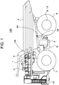
- FIG. 1 is a side view of a dump truck which is a typical example of the work vehicle.
- a body (also referred to as a vessel) 4 for loading soil and the like is mounted on a frame 36, and both the frame 36 and the body 4 are connected to each other by hoist cylinders 33.
- the expansion and contraction operation of the hoist cylinders 33 rotate the body 4 in a vertical direction.
- front wheels 7, rear wheels 8, a hydraulic oil tank 6, and a fuel tank 5 are attached to the frame 36 through mechanical parts (not shown).
- a rotating shaft portion of each rear wheel 8 houses a traveling motor 10 for driving the rear wheel 8 and a reduction gear 9 which mechanically connects the rear wheel 8 and the traveling motor 10.
- the front wheels 7, the rear wheels 8, the traveling motors 10, and the reduction gears 9 are provided as a pair on the left and right, and in the following description, "L” and "R” are appropriately added after the reference numerals to distinguish the left and right.
- a deck 28 on which an operator can walk is attached to the frame 36.
- a cab 2 on which the operator rides to operate the dump truck 100 On an upper surface of the deck 28 are mounted a cab 2 on which the operator rides to operate the dump truck 100, a control cabinet 1 in which various power devices are stored, and a plurality of grid boxes 3 for dissipating an excess energy as a heat.
- an engine 11 and a main generator (first generator) 12 as an electric power source for a traveling motor
- an auxiliary generator as an electric power source for an auxiliary device (second generator) 13
- a main pump not shown
- an accelerator pedal, a brake pedal, a hoist lever, and a steering wheel (not shown) are provided.
- the operator can control an acceleration force and a braking force of the dump truck 100 by the depression amount of the accelerator pedal and the brake pedal in the cab 2. Further, the operator can perform a steering operation by a hydraulic drive by rotating the steering wheel to the left and right, and perform body elevating operation by the hydraulic drive by beat hoist lever back and forth.
- the system for steering operation and body lifting operation is the same as in the prior art, and therefore, will not be described in detail in this embodiment.
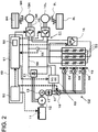
- FIG. 2 is a block diagram of the electric power regeneration system for the dump truck according to the present embodiment.
- the power regeneration system of the dump truck 100 is roughly configured by an engine 11, a main generator 12, an auxiliary generator 13, a first electric circuit C1, a second electric circuit C2, and a DC/DC converter (step-down device) 60 and a controller 49.
- the main generator 12 and the auxiliary generator 13 are mechanically connected to the engine 11 and driven by the engine 11.
- the first electric circuit C1 supplies an electric power generated by the main generator 12 to traveling motors 10L and 10R connected to rear wheels (driving wheels) 8L and 8R of the dump truck 100.
- the second electric circuit C2 supplies the electric power generated by the auxiliary generator 13 to grid box fan motors (auxiliary motors) connected to grid box fans (auxiliary device) 19 of the dump truck 100.
- a high voltage side of the DC/DC converter 60 is connected to the first electric circuit C1, and the low voltage side is connected to the second electric circuit C2. Then, the DC/DC converter 60 supplies an electric power from the first electric circuit C1 to the second electric circuit C2.
- a three-phase AC output of the main generator 12 is input to high voltage DC line inverters 15L and 15R through a main generator diode bridge 21 and a high voltage DC line 56, and the outputs of the high voltage DC line inverters 15L and 15R are connected to the traveling motors 10L and 10R, respectively.
- the output shafts of the traveling motors 10L and 10R are mechanically connected to rear wheels 8L and 8R through reduction gears 9L and 9R, respectively.
- the high voltage DC line 56 is connected to the grid box resistors 53 and the chopper 16 in addition to DC input sections of the high voltage DC line inverters 15L and 15R described above.
- the high voltage DC line 56 is also connected to a voltmeter (voltage detector) 55 for detecting a voltage.
- a three-phase AC output of the auxiliary generator 13 is input to the auxiliary device DC line inverter 18 through an auxiliary generator diode bridge 17 and an auxiliary device DC line 57, and an output of the auxiliary device DC line inverter 18 is connected to multiple grid box fan motors 54.
- the output shafts of the grid box fan motors 54 are mechanically connected to the grid box fans 19.
- the controller 49 includes a main controller 50 and a power controller 51.
- the controller 49 is configured by hardware including a CPU (Central Processing Section), a storage device 52 such as a ROM (Read Only Memory) or an HDD (Hard disc Drive) for storing various programs for executing processing by the CPU, and a RAM (Random Access Memory) which is a work area when the CPU executes the programs.
- a CPU Central Processing Section
- a storage device 52 such as a ROM (Read Only Memory) or an HDD (Hard disc Drive) for storing various programs for executing processing by the CPU
- a RAM Random Access Memory
- the main controller 50 integrally controls the engine 11 and the power controller 51 based on a state of the dump truck 100 and an operation input of the operator.
- the power controller 51 inputs on-off signals appropriately to respective semiconductor switches (not shown) of the high voltage DC line inverters 15L, 15R, the chopper 16, and the auxiliary device DC line inverter 18 under the control of the main controller 50, and drives the traveling motors 10L and 10R, the grid box resistance (resistor) 53, and the grid box fan motors 54 with appropriate timing and appropriate output, to thereby control a flow of the electric power of the first electric circuit C1 and the second electric circuit C2.
- the power controller 51 determines whether or not the dump truck 100 travels in a traveling state in which the regenerative power is obtained, that is, determines whether or not the traveling motors 10L and 10R to control the drive of the DC/DC converter 60.
- the main generator 12 When the main generator 12 is driven by the engine 11, the generated three-phase AC voltage is converted in to a DC voltage by the main generator diode bridge 21 and the DC voltage is input to the high voltage DC line inverters 15R and 15L through the high voltage DC line 56.
- the power controller 51 inputs a control signal for acceleration to the high voltage DC line inverters 15L and 15R, and supplies an electric power to the traveling motors 10L and 10R.
- the traveling motors 10L and 10R drive the rear wheels 8L and 8R through the reduction gears 9L and 9R by the electric power to move a vehicle body forward or backward.
- the power controller 51 inputs a control signal for deceleration to the high voltage DC line inverters 15L and 15R, and the traveling motors 10L and 10R convert a kinetic energy of the vehicle body into an electric energy.
- the traveling motors 10L and 10R operate as generators.
- a torque is generated in the traveling motors 10L and 10R in a direction opposite to the rotation direction.
- the power controller 51 operates the chopper 16 to supply the electric power to the grid box resistors 53.
- a surplus electric power generated by the regeneration operation of the traveling motors 10L and 10R is consumed by converting an electric energy into a heat by applying a DC voltage to grid box resistors 53.
- the heat of the grid box resistors 53 is normally air cooled naturally by the surrounding atmosphere. However, when the heat generation amount is large, a temperature of the grid box resistors 53 rises, which may cause a damage due to a high temperature. For that reason, the power controller 51 drives the grid box fan motors 54 to cool the grid box resistors 53 by forced air cooling.
- the auxiliary generator 13 When the auxiliary generator 13 is driven by the engine 11, the generated three-phase AC voltage is converted into a DC voltage by the diode bridge 17 for the auxiliary generator, and the DC voltage is input to the auxiliary device DC line inverter 18 through the auxiliary device DC line 57.
- a control signal for driving the grid box fan motors is input from the power controller 51 to the auxiliary device DC line inverter 18, and the electric power is supplied to the grid box fan motors 54. This power causes the grid box fan motors 54 to rotate the mechanically connected grid box fans 19.
- the power controller 51 performs calculation to estimate the input voltage after a predetermined time to the high voltage DC line inverters 15L and 15R from the amount of power generation of the traveling motors 10L and 10R.
- the power controller 51 outputs a control signal for operating the grid box fans 19 to the DC/DC converter 60.
- the DC/DC converter 60 converts a voltage of the high voltage DC line 56 into a voltage of the auxiliary device DC line 57 based on the input of the control signal from the power controller 51 and applies the converted voltage to the auxiliary device DC line inverter 18.
- the electric power generated by the traveling motors 10L and 10R is sent to the grid box fans 19 before flowing into the grid box resistors 53 through the chopper 16, and consumed by the grid box fans 19, thereby being capable of not only effectively using the electric power generated by the traveling motors 10L and 10R but also delaying the operation of the chopper 16 by inhibiting a voltage rise of the high voltage DC line 56, which makes it possible to inhibit the heat generation of the grid box resistors 53 and to extend the lifetime of the grid box resistors 53.
- FIG. 3 is a block diagram showing an internal configuration of the power controller 51.
- the power controller 51 includes a resistor drive determination section 101, a traveling state determination section 102, a voltage estimation section 103, a DC/DC drive determination section (step-down device drive determination section) 104, and a DC/DC control section (step-down device control section) 105.
- the resistor drive determination section 101 determines whether or not the actual voltage V of the high voltage DC line 56 (first electric circuit C1) output by the voltmeter 55 exceeds the threshold Vth, and outputs a drive command to the chopper 16 when the actual voltage V exceeds the threshold Vth.
- the traveling state determination section 102 determines whether or not the traveling motors 10L and 10R are performing a regenerative operation based on the information related to the traveling state of the dump truck 100.
- the traveling state determination section 102 determines whether the positive and negative signs of output values of the torque sensor 25 for detecting the output torque of the traveling motors 10L and 10R, and the rotational speed sensor 26 for detecting the rotational speeds of traveling motors 10L and 10R (torque: TL, TR / rotational speed: ⁇ L, ⁇ R) match each other (details will be described later), and if not matching, the traveling state determination section 102 assumes that the traveling motors 10L and 10R generate the electric power, that is, the regeneration operation is performed, and transmits an operation command to the voltage estimation section 103.
- the suffixes L of the torque T and the rotational speed ⁇ indicate the torque and the rotational speed of the left traveling motor 10L
- the subscripts R indicate the torque and the rotational speed of the right traveling motor 10R.
- the torque sensor 25 and the rotational speed sensor 26 are provided on the traveling motors 10L and 10R, though not shown.
- the voltage estimation section 103 estimates a tendency of a change in the voltage of the high voltage DC line 56 according to the outputs (TL, TR) of the torque sensor 25, the outputs ( ⁇ L, ⁇ R) of the rotational speed sensor 26, and the actual voltage V output from the voltmeter 55, estimates the voltage V* of the high voltage DC line 56 after a predetermined time ts from the current time (reference time), and outputs the estimated voltage V* to the DC/DC drive determination section 104.
- the DC/DC drive determination section 104 compares the voltage V* of the high voltage DC line 56 after the predetermined time ts estimated by the voltage estimation section 103 with the threshold Vth, and outputs a DC/DC converter drive command to the DC/DC control section 105 when the voltage V* is equal to or higher than the threshold Vth.
- the DC/DC control section 105 controls the DC/DC converter 60 so as to set the output voltage of the DC/DC converter 60 to a desired voltage.
- the electric power is supplied from the high voltage DC line 56 (first electric circuit C1) to the auxiliary device DC line 57 (second electric circuit C2) through the DC/DC converter 60.
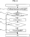
- FIG. 4 is a flowchart illustrating a procedure of a control process of the DC/DC converter.
- the power controller 51 starts the processing operation together with the activation of the vehicle body (for example, the key switch on of the engine 11).
- the traveling state determination section 102 acquires the traveling state of the vehicle body from the torque sensor 25 and the rotational speed sensor 26, that is, the torques TL and TR and the rotational speeds ⁇ L and ⁇ R of the traveling motors 10L and 10R.
- the voltage estimation section 103 and the resistor drive determination section 101 acquire the actual voltage V of the high voltage DC line 56 from the voltmeter 55.
- Step S2 the traveling state determination section 102 determines whether or not the positive and negative signs of the torque TL and TR of the traveling motors 10L and 10R match the positive and negative signs of the rotational speeds ⁇ L and ⁇ R, thereby determining whether or not the power generation is performed by the traveling motors 10L and 10R. If the traveling motors 10L and 10R are in a powering operation while the vehicle body is accelerated forward, the signs of the torque and the rotational speed are both positive and match each other. On the other hand, when the vehicle is decelerated forward and the traveling motors 10L and 10R are in the regeneration operation, the sign of the torque is negative and the sign of the rotational speed is positive and do not match each other. Similarly, during reverse acceleration, both the signs of the torque and the rotational speed are negative and match each other, and during the reverse deceleration, the torque is positive and the rotational speed is negative, and the signs of the torque and the rotational speed do not match each other.
- the traveling state determination section 102 determines that power generation is performed by the traveling motors 10L and 10R, and the process proceeds to Step S3. On the other hand, when the signs match each other (No in S2), the traveling state determination section 102 determines that the power generation is not performed by the traveling motors 10L and 10R, and ends a series of operations.
- Step S3 the voltage estimation section 103 predicts the tendency of a change in the voltage of the high voltage DC line 56 according to the traveling state of the vehicle body (torques TL and TR and the rotational speeds ⁇ L and ⁇ R of the traveling motors 10L and 10R) and the actual voltage V of the voltmeter 55.
- the voltage estimation section 103 estimates from the predicted tendency, the voltage V* of the high voltage DC line 56 after a predetermined time ts from the current time by a calculation expression to be described later.
- the DC/DC drive determination section 104 compares the estimated voltage V* with the threshold Vth. If the voltage V* is smaller than the threshold Vth (No in S4), a series of operations is completed.
- Step S5 the DC/DC control section 105 outputs a control command to the DC/DC converter 60 and ends a series of operations.
- the power controller 51 repeatedly performs the operations in Steps S1 to S5 in a predetermined cycle (for example, every 10 ms) until the activation of the vehicle body starts and then stops. In other words, the power controller 51 sequentially acquires the detection data of the torque sensor 25, the rotational speed sensor 26, and the voltmeter 55, estimates the voltage V* after a predetermined time ts, and controls the DC/DC converter 60.
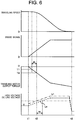
- FIG. 5 is a time chart showing changes in vehicle body operation in time series.
- the braking operation at the time of stopping the vehicle body will be described as an example.
- a graph 5-1 of FIG. 5 when the dump truck 100 travels at a certain traveling speed, if the braking is started at a time t1, the traveling speed gradually decreases and the dump truck 100 stops at a time t2.
- the actual voltage V of the high voltage DC line 56 starts to rise from the time t1 and rises to a maximum voltage Vmax.
- the actual voltage V indicated by a dashed line Lc is larger than the threshold Vth (actual voltage V > threshold Vth)
- the chopper 16 operates, and an electric power generated by the traveling motors 10L and 10R is consumed by the grid box resistors 53.
- the power controller 51 sequentially calculates the voltage V* of the high voltage DC line 56 after a predetermined time ts from the current time, and predicts the voltage V* after ts seconds from the current time as indicated by a one-dot chain line (the details will be described later).
- the predetermined time ts is an arbitrary time set shorter than a time from a braking start (t1) to an intersection point of an approximate curve in a region where a change in braking output (refer to graph 5-1) is linear and a time axis.
- the DC/DC converter 60 is turned on (graph 5-4), and an electric power is supplied to the auxiliary device DC line 57 from the high voltage DC line 56 through the DC/DC converter 60.
- the grid box fan motors 54 are driven by the electric power (regenerated power) generated by the traveling motors 10L and 10R.
- the output of the auxiliary generator 13 becomes almost zero.
- a rise of the voltage of the high voltage DC line 56 becomes slower than a voltage rise (a dashed line Lc) of the conventional example, and as indicated by a graph 5-3, the operation of the chopper 16 is delayed by a time tc as compared with the conventional example.
- the power consumption time of the grid box resistors 53 is shortened, and the operation time of the grid box fan motors 54, which are auxiliary devices, is extended. Also, once the DC/DC converter 60 operates, the DC/DC converter 60 continues to operate until the braking operation by the traveling motors 10L and 10R ends. As a result, since the DC/DC converter 60 supplies an electric power to the grid box fan motors 54 from the time t3 to the time t2, a load of the auxiliary generator 13 and hence the engine 11 can be reduced by an area of a hatched area in a graph 5-5, that is, (power required by grid box fans) x (t2-t3), and the fuel efficiency can be improved.
- FIG. 6 is a diagram illustrating a method of estimating the voltage V*.
- the voltage estimation section 103 sequentially acquires the traveling state of the vehicle body, for example, the output torques TL and TR and rotational speeds ⁇ L and ⁇ R of the traveling motors 10L and 10R, and the actual voltage V output from the voltmeter 55.
- the voltage estimation section 103 predicts a tendency of a change in the voltage of the high voltage DC line 56 from the output torques TL, Tr, the rotational speeds ⁇ L, ⁇ R, and the actual voltage V, which have been acquired.
- the brake pedal is depressed at the time t1 during traveling at a certain predetermined speed, and when a brake signal increases, the output torques of the traveling motors 10L and 10R increase toward a negative direction in order to decrease the speed, and the voltage of the high voltage DC line 56 also increases accordingly.
- the voltage estimation section 103 stores the output torques of the traveling motors 10L and 10R in advance, and estimates a torque Ts after a predermined time ts seconds through Expression (1) from a current output torque T2 and an output torque T1 before a certain time ⁇ t.
- Ts T 2 ⁇ T 1 / ⁇ ⁇ t ⁇ ts + T 2
- the voltage estimation section 103 stores the rotational speeds of the traveling motors 10L and 10R in advance, and estimates a rotational speed ⁇ s after the predetermined time ts seconds through Expression (2) from a current rotational speed ⁇ 2 and a rotational speed ⁇ 1 before a certain time ⁇ t.
- ⁇ ⁇ s ⁇ 2 ⁇ ⁇ 1 / ⁇ ⁇ t ⁇ ts + ⁇ 2
- the voltage estimation section 103 calculates a motor output Pms of the traveling motors 10L and 10R after the predetermined time ts through Expression (3) from the torque Ts and the rotational speed ⁇ s after the predetermined time ts seconds.
- Pms Ts ⁇ ⁇ s
- the voltage estimation section 103 calculates a current motor output Pm of the traveling motors 10L and 10R through Expression (4) from the current torque T2 and rotational speed ⁇ 2.
- Pm T 2 ⁇ ⁇ 2
- the voltage estimation section 103 calculates power generation amounts Pes and Pe of the respective traveling motors 10L and 10R through Expressions (5) and (6) from the motor output Pm and a power generation efficiency ⁇ e.
- Pe Pm ⁇ ⁇ e
- Pes Pms ⁇ ⁇ e
- the power generation efficiency ⁇ e is a value determined according to the specifications and the use situations of the traveling motors 10L and 10R, such as an input voltage, a frequency, and an input current.
- the power generation efficiency ⁇ e is stored in advance in the form of a table to determine each power generation amount with reference to the table for each use sitaution.
- the voltage estimation section 103 applies Expressions (5) and (6) for calculating the traveling motor power generation amounts Pe and Pes to the left and right traveling motors 10L and 10R, and calculates respective power generation amounts PesL, PesR, PeL, and PeR.
- the voltage estimation section 103 estimates the voltage V* of the high voltage DC line 56 after the time ts through Expression (7) from the power generation amounts PesL, Pesr, PeL, and PeR of those traveling motors 10L and 10R, a capacitance C of the high voltage DC line 56, and the actual voltage V from the voltmeter 55.
- V * PesL + PesR + PeL + PeR / 2 ⁇ ts / C + V 2 0.5
- the tendency of a change in the voltage of the high voltage DC line 56 is derived from the state of the vehicle body, and the voltage V* after the predetermined time can be estimated.
- the DC/DC converter 60 can be activated before the chopper 16 is driven.
- the electric power generated by the traveling motors 10L and 10R can be supplied to the grid box fans (auxiliary devices) 19 before being consumed by the grid box resistors 53, voltage rise of the high voltage DC line 56 is reduced to delay the operation of the grid box resistors 53, and the electric power can be supplied to the grid box fans 19 for a longer time.
- This makes it possible to perform the output reduction of the auxiliary generator 13 which has generated the electric power for driving the grid box fan 19, the output reduction of the engine 11 for driving the auxiliary generator 13, thereby improving the fuel efficiency.
- FIG. 7 is a flowchart showing a modification of a procedure of a control process of the DC/DC converter.
- the control process of the DC/DC converter according to the modification adds processing of Steps S5-1 and S5-2 to the processing shown in FIG. 4 after Step S5.
- Step S5-1 the voltage estimation section 103 acquires the current traveling state of the vehicle body (torque and rotational speed). Then, in Step S5-2, similarly to Step S2, the traveling state determination section 102 determines whether or not the power generation is performed by the traveling motors 10L and 10R, and when the power generation is performed by the traveling motors 10L and 10R (yes in S5-2), the process returns to Step S5, and a control command is continuously output to the DC/DC converter 60. On the other hand, when the power generation is not performed by the traveling motors 10L and 10R (no in S5-2), a series of operations are ended.
- FIG. 8 is a flowchart showing a procedure of the method of estimating the voltage V* according to the second embodiment.
- a voltage estimation section 103 calculates the voltage V* without using a power generation amount Pes after a predetermined time ts seconds to reduce a calcuation load, which is different from the method of estimating the voltage* in the first embodiment.
- Step S61-1 the voltage estimation section 103 calculates outputs PmL and PmR of traveling motors 10L and 10R from sequentially acquired vehicle body information, such as torque TL and TR of traveling motors 10L and 10R and rotational speeds ⁇ L and ⁇ R through the following Expression (8).
- PmL TL ⁇ ⁇ ⁇ L
- PmR TR ⁇ ⁇ R
- Step S62-1 the voltage estimation section 103 calculates power generation amounts PeL and PeR of the traveling motors 10L and 10R through the following Expression (9) from the outputs PmL and PmR of the traveling motors 10L and 10R, and a power generation efficiency ⁇ e.
- PeL PmL ⁇ ⁇ ⁇ e
- PeR PmR ⁇ ⁇ e
- Step S63 the voltage estimation section 103 estimates the voltage V* input to high voltage DC line inverters 15L and 15R after a predetermined timt ts seconds through Expression (10) from the power generation amounts PeL and PeR of the traveling motors 10L and 10R, a disturbance Pl, an electrostatic capacitance C of the high voltage DC line 56, and an actual voltage V output from a voltmeter 55.
- the disturbance P1 indicates an electric power necessary for driving the loads other than the traveling motors 10L and 10R and grid box resistors 53 connected to the high voltage DC line 56.
- V * PeL + PeR ⁇ P1 ⁇ ts / C + V 2 0.5
- the same advantages as those of the first embodiment can be obtained, and the calculation load of the power controller 51 when the voltage V* is estimated can be reduced compared to the first embodiment.
- FIG. 9 is a flowchart showing a procedure of the method of estimating the voltage V* according to the third embodiment.
- a voltage estimation section 103 omits the steps of calculating outputs PmL and PmR of traveling motors 10L and 10R using torques TL and TR, and obtains power generation amounts PeL and PeR of the traveling motors 10L and 10R from rotational speeds ⁇ L and ⁇ R of the traveling motors, a brake signals, and a lookup table LUT, and a calculation load is further reduced more than that in the second embodiment.
- the voltage estimation section 103 obtains the power generation amounts PeL and PeR of the traveling motors 10L and 10R with reference to the lookuptable LUT stored in advance, from successively acquired vehicle information, for example, absoluate values of the rotational speeds ⁇ L and ⁇ R of the traveling motors 10L and 10R, and a brake signal ⁇ R.
- the lookup table LUT is stored in advance in a storage device 52 in the power controller 51 (refer to FIG. 2 ).
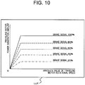
- FIG. 10 is a diagram showing a lookup table used when estimating the voltage V* in the third embodiment.
- the lookup table LUT a relationship among the rotational speeds of the traveling motors 10L and 10R, the brake signal, and the power generation amounts of the traveling motors 10L and 10R is defined.
- a horizontal axis represents absolute values of the rotational speed of the traveling motors 10L and 10R
- a vertical axis represents the amount of power generation of the traveling motors 10L and 10R
- line types represent differences for each brake signal.
- the lookup table LUT is created according to the output characteristics and the control characteristics of the traveling motors 10L and 10R, and can be created when the traveling motors 10L, 10R and the control specifications are determined.
- Step S62 the voltage estimation section 103 calculates the voltage V* input to the high voltage DC line inverters 15L and 15R after a predetermined time ts second through Expression (11).
- V * PeL + PeR ⁇ P1 ⁇ ts / C + V 2 0.5
- the power generation amount is obtained from the lookup table LUT based on the rotational speeds of the traveling motors 10L and 10R and the brake signal, thereby reducing the sensors and processing required, and improving the control responsiveness.
- the present invention is not limited to the embodiments described above, but includes various modifications.
- the embodiments described above are described in detail to described the present invention in an easy-to-understand manner, and is not necessarily limited to one having all the described configurations.
- the rotational speed and torque of the traveling motors 10L and 10R are used, but the present invention is not limited to the above configuration, and it may be determined whether or not there is the regenerative operation according to the rotational speed of the traveling motors 10L and 10R and the brake signal.
- the grid box fan motors 54 are used to supply the electric power from the DC/DC converter 60.
- the present invention is not limited to the above configuration, and the grid box fan motors 54 may be used to supply the electric power to another auxiliary device, or may be used to supply the electric power to a plurality of auxiliary devices.
Abstract
Description
- The present invention relates to a power regeneration system for a work vehicle.
- In a dump truck, which is an example of a work vehicle, there is an electrically driven dump truck that travels by driving a traveling motor with an electric power generated by a generator mechanically connected to an engine. The electrically driven dump truck of this type is used, for example, in a mine, and at the time of deceleration, the traveling motor is driven as the generator to convert a vehicle body kinetic energy into an electric energy and performs a regenerative operation to obtain a braking force. If the electric energy regenerated (generated) by the traveling motor is not consumed, a braking performance is reduced, and therefore there is a need to consume the regenerated electric energy in some way.
- As a technique for consuming the regenerated electric energy, for example,
Patent Literature 1 discloses a configuration of "in a power conversion system for an electric vehicle including a discharge dedicated circuit that discharges electric charge stored in a smoothing capacitor, a control circuit that controls the power conversion system for the electric vehicle includes a discharge control section that drives a DC/DC converter to feed the electric charge stored in the smoothing capacitor to an auxiliary device or a DC auxiliary power supply of the vehicle and discharges the electric charge when the control circuit detects a failure in a discharge dedicated circuit (refer to Abstract). - [PATENT LITERATURE 1] Japanese Patent Application Laid-Open Publication No.
2015-073409 - However, in the electrically driven dump truck for mines, an electric power regenerated by the traveling motor is much larger than an electric power required for the auxiliary devices. For that reason, a method of consuming all the electric energy regenerated by the traveling motor with an auxiliary device as in
Patent Literature 1 cannot be applied. Moreover, inPatent Literature 1, a timing at which to drive the DC/DC converter (step-down device) is only when a failure of a resistor is detected, and an opportunity which consumes the electric energy regenerated by the traveling motor by the auxiliary device is small. The electric energy regenerated by the traveling motor cannot be used effectively. - Therefore, an object of the present invention is to provide a power regeneration system for a work vehicle which can effectively utilize a regenerated electric energy even when the electric energy regenerated by a traveling motor is larger than an output of an accessory machine.
- In order to solve the above problem, according to an aspect of the present invention, there is provided a power regeneration system for a work vehicle including: a first generator and a second generator which are driven by an engine; a first electric circuit for supplying an electric power generated by the first generator to a traveling motor to a driving wheel of the work vehicle; a resistor that is connected to the first electric circuit and converts an electric energy generated at the time of braking of the traveling motor into a heat energy and radiates the heat energy; a voltage detector that detects an actual voltage of the first electric circuit; a second electric circuit for supplying an electric power generated by the second generator to the auxiliary device of the work vehicle; a step-down device that has a high voltage side connected to the first electric circuit and a low voltage side connected to the second electric circuit, and supplies the electric power from the first electric circuit to the second electric circuit; and
a controller that controls driving of the step-down device, in which the controller includes: a resistor drive determination section that determines whether or not the actual voltage is equal to or more than a predetermined threshold, and outputs a drive command to the resistor when the actual voltage becomes equal to or more than the threshold; a traveling state determination section that determines whether or not the traveling motor performs the regenerative operation, based on information on a traveling state of the work vehicle; a voltage estimation section that estimates a voltage of the first electric circuit after a predetermined time from the present time, based on the information on the traveling state of the work vehicle and the actual voltage detected by the voltage detector; a step-down device drive determination section that determines whether or not the voltage estimated by the voltage estimation section is equal to or more than the threshold, and determines that the step-down device is driven when the voltage estimated by the voltage estimation section is equal to or more than the threshold; and a step-down device control section that outputs a drive command to the step-down device when the traveling state determination section determines that the traveling motor performs the regeneration operation and the step-down device drive determination section determines that the step-down device is driven. - According to the present invention, even when the electric energy regenerated by the traveling motor is larger than the output of the auxiliary device, the regenerated electric energy can be effectively used. In addition, the problems, the configurations, and the effects except for those mentioned above will be clarified by description of the following embodiment.
-
- [
FIG. 1] FIG. 1 is a side view of a dump truck that is a representative example of a work vehicle. - [
FIG. 2] FIG. 2 is a configuration diagram of a power regeneration system for a dump truck according to the present embodiment. - [
FIG. 3] FIG. 3 is a block diagram showing an internal configuration of a power controller. - [
FIG. 4] FIG. 4 is a flowchart showing a procedure of a control process of a DC/DC converter. - [
FIG. 5] FIG. 5 is a time chart showing changes in vehicle operation in time series. - [
FIG. 6] FIG. 6 is a diagram illustrating a method of estimating a voltage V*. - [
FIG. 7] FIG. 7 is a flowchart showing a modification of the procedure of a control process of the DC/DC converter. - [
FIG. 8] FIG. 8 is a flowchart showing a procedure of a method of estimating a voltage V* according to a second embodiment. - [
FIG. 9] FIG. 9 is a flowchart showing a procedure of a method of estimating a voltage V* according to a third embodiment. - [
FIG. 10] FIG. 10 is a diagram showing a lookup table used when estimating the voltage V* in the third embodiment. - Hereinafter, embodiments of the present invention will be described with reference to the drawings. In the drawings, the same elements will be denoted by the same reference symbols and redundant description will be omitted.
- Hereinafter, a power regeneration system for a work vehicle according to a first embodiment of the present invention will be described. The power regeneration system according to the first embodiment of the present invention is an example applied to a dump truck that is a typical example of a work vehicle.
-
FIG. 1 is a side view of a dump truck which is a typical example of the work vehicle. In adump truck 100, a body (also referred to as a vessel) 4 for loading soil and the like is mounted on aframe 36, and both theframe 36 and thebody 4 are connected to each other by hoistcylinders 33. The expansion and contraction operation of the hoistcylinders 33 rotate thebody 4 in a vertical direction. In addition,front wheels 7,rear wheels 8, a hydraulic oil tank 6, and a fuel tank 5 are attached to theframe 36 through mechanical parts (not shown). A rotating shaft portion of eachrear wheel 8 houses a traveling motor 10 for driving therear wheel 8 and a reduction gear 9 which mechanically connects therear wheel 8 and the traveling motor 10. Thefront wheels 7, therear wheels 8, the traveling motors 10, and the reduction gears 9 are provided as a pair on the left and right, and in the following description, "L" and "R" are appropriately added after the reference numerals to distinguish the left and right. - Further, a
deck 28 on which an operator can walk is attached to theframe 36. On an upper surface of thedeck 28 are mounted acab 2 on which the operator rides to operate thedump truck 100, acontrol cabinet 1 in which various power devices are stored, and a plurality ofgrid boxes 3 for dissipating an excess energy as a heat. Further, inFIG. 1 , in a portion hidden by thefront wheels 7, anengine 11 and a main generator (first generator) 12 as an electric power source for a traveling motor, an auxiliary generator as an electric power source for an auxiliary device (second generator) 13, and a main pump (not shown) as a hydraulic pressure source for hydraulic equipment are mounted. - Next, a method of operating the
dump truck 100 will be described. In thecab 2, an accelerator pedal, a brake pedal, a hoist lever, and a steering wheel (not shown) are provided. The operator can control an acceleration force and a braking force of thedump truck 100 by the depression amount of the accelerator pedal and the brake pedal in thecab 2. Further, the operator can perform a steering operation by a hydraulic drive by rotating the steering wheel to the left and right, and perform body elevating operation by the hydraulic drive by beat hoist lever back and forth. The system for steering operation and body lifting operation is the same as in the prior art, and therefore, will not be described in detail in this embodiment. -
FIG. 2 is a block diagram of the electric power regeneration system for the dump truck according to the present embodiment. As shown inFIG. 2 , the power regeneration system of thedump truck 100 is roughly configured by anengine 11, amain generator 12, an auxiliary generator 13, a first electric circuit C1, a second electric circuit C2, and a DC/DC converter (step-down device) 60 and acontroller 49. Themain generator 12 and the auxiliary generator 13 are mechanically connected to theengine 11 and driven by theengine 11. - The first electric circuit C1 supplies an electric power generated by the
main generator 12 to travelingmotors dump truck 100. The second electric circuit C2 supplies the electric power generated by the auxiliary generator 13 to grid box fan motors (auxiliary motors) connected to grid box fans (auxiliary device) 19 of thedump truck 100. - A high voltage side of the DC/
DC converter 60 is connected to the first electric circuit C1, and the low voltage side is connected to the second electric circuit C2. Then, the DC/DC converter 60 supplies an electric power from the first electric circuit C1 to the second electric circuit C2. - In the first electric circuit C1, a three-phase AC output of the
main generator 12 is input to high voltageDC line inverters generator diode bridge 21 and a highvoltage DC line 56, and the outputs of the high voltageDC line inverters traveling motors traveling motors rear wheels reduction gears voltage DC line 56 is connected to thegrid box resistors 53 and thechopper 16 in addition to DC input sections of the high voltageDC line inverters voltage DC line 56 is also connected to a voltmeter (voltage detector) 55 for detecting a voltage. - On the other hand, a three-phase AC output of the auxiliary generator 13 is input to the auxiliary device
DC line inverter 18 through an auxiliarygenerator diode bridge 17 and an auxiliarydevice DC line 57, and an output of the auxiliary deviceDC line inverter 18 is connected to multiple gridbox fan motors 54. The output shafts of the gridbox fan motors 54 are mechanically connected to thegrid box fans 19. - The
controller 49 includes amain controller 50 and apower controller 51. Although not shown, thecontroller 49 is configured by hardware including a CPU (Central Processing Section), astorage device 52 such as a ROM (Read Only Memory) or an HDD (Hard disc Drive) for storing various programs for executing processing by the CPU, and a RAM (Random Access Memory) which is a work area when the CPU executes the programs. - The
main controller 50 integrally controls theengine 11 and thepower controller 51 based on a state of thedump truck 100 and an operation input of the operator. Thepower controller 51 inputs on-off signals appropriately to respective semiconductor switches (not shown) of the high voltageDC line inverters chopper 16, and the auxiliary deviceDC line inverter 18 under the control of themain controller 50, and drives the travelingmotors box fan motors 54 with appropriate timing and appropriate output, to thereby control a flow of the electric power of the first electric circuit C1 and the second electric circuit C2. - Although will be described in detail later, the
power controller 51 determines whether or not thedump truck 100 travels in a traveling state in which the regenerative power is obtained, that is, determines whether or not the travelingmotors DC converter 60. - Next, a detailed flow of the electric power generated by the
main generator 12 will be described. When themain generator 12 is driven by theengine 11, the generated three-phase AC voltage is converted in to a DC voltage by the maingenerator diode bridge 21 and the DC voltage is input to the high voltageDC line inverters voltage DC line 56. In this state, when the operator depresses an accelerator pedal or an accelerator signal is output to thepower controller 51 by an autonomous driving function, thepower controller 51 inputs a control signal for acceleration to the high voltageDC line inverters motors motors rear wheels - On the other hand, when the operator depresses the brake pedal to perform the braking operation at the time of downhill or stop, or when a brake signal is output to the
power controller 51 due to the autonomous driving function (refer toFIG. 3 ), thepower controller 51 inputs a control signal for deceleration to the high voltageDC line inverters motors motors motors voltage DC line 56 rises due to the generated electric energy, thepower controller 51 operates thechopper 16 to supply the electric power to thegrid box resistors 53. - As a result, a surplus electric power generated by the regeneration operation of the traveling
motors grid box resistors 53. The heat of thegrid box resistors 53 is normally air cooled naturally by the surrounding atmosphere. However, when the heat generation amount is large, a temperature of thegrid box resistors 53 rises, which may cause a damage due to a high temperature. For that reason, thepower controller 51 drives the gridbox fan motors 54 to cool thegrid box resistors 53 by forced air cooling. - Next, a method of driving the grid
box fan motors 54 will be described. When the auxiliary generator 13 is driven by theengine 11, the generated three-phase AC voltage is converted into a DC voltage by thediode bridge 17 for the auxiliary generator, and the DC voltage is input to the auxiliary deviceDC line inverter 18 through the auxiliarydevice DC line 57. When thegrid box resistors 53 need to be cooled, a control signal for driving the grid box fan motors is input from thepower controller 51 to the auxiliary deviceDC line inverter 18, and the electric power is supplied to the gridbox fan motors 54. This power causes the gridbox fan motors 54 to rotate the mechanically connectedgrid box fans 19. - At this time, although the details will be described later, the
power controller 51 performs calculation to estimate the input voltage after a predetermined time to the high voltageDC line inverters motors power controller 51 outputs a control signal for operating thegrid box fans 19 to the DC/DC converter 60. The DC/DC converter 60 converts a voltage of the highvoltage DC line 56 into a voltage of the auxiliarydevice DC line 57 based on the input of the control signal from thepower controller 51 and applies the converted voltage to the auxiliary deviceDC line inverter 18. - As a result, the electric power generated by the traveling
motors grid box fans 19 before flowing into thegrid box resistors 53 through thechopper 16, and consumed by thegrid box fans 19, thereby being capable of not only effectively using the electric power generated by the travelingmotors chopper 16 by inhibiting a voltage rise of the highvoltage DC line 56, which makes it possible to inhibit the heat generation of thegrid box resistors 53 and to extend the lifetime of thegrid box resistors 53. - Next, the functions in the
power controller 51 will be described with reference toFIG. 3. FIG. 3 is a block diagram showing an internal configuration of thepower controller 51. As shown inFIG. 3 , thepower controller 51 includes a resistordrive determination section 101, a travelingstate determination section 102, avoltage estimation section 103, a DC/DC drive determination section (step-down device drive determination section) 104, and a DC/DC control section (step-down device control section) 105. - The resistor
drive determination section 101 determines whether or not the actual voltage V of the high voltage DC line 56 (first electric circuit C1) output by thevoltmeter 55 exceeds the threshold Vth, and outputs a drive command to thechopper 16 when the actual voltage V exceeds the threshold Vth. The travelingstate determination section 102 determines whether or not the travelingmotors dump truck 100. Specifically, the travelingstate determination section 102 determines whether the positive and negative signs of output values of thetorque sensor 25 for detecting the output torque of the travelingmotors rotational speed sensor 26 for detecting the rotational speeds of travelingmotors state determination section 102 assumes that the travelingmotors voltage estimation section 103. In this example, the suffixes L of the torque T and the rotational speed ω indicate the torque and the rotational speed of theleft traveling motor 10L, and the subscripts R indicate the torque and the rotational speed of theright traveling motor 10R. Thetorque sensor 25 and therotational speed sensor 26 are provided on the travelingmotors - When the determination result that the traveling
motors state determination section 102, thevoltage estimation section 103 estimates a tendency of a change in the voltage of the highvoltage DC line 56 according to the outputs (TL, TR) of thetorque sensor 25, the outputs (ωL, ωR) of therotational speed sensor 26, and the actual voltage V output from thevoltmeter 55, estimates the voltage V* of the highvoltage DC line 56 after a predetermined time ts from the current time (reference time), and outputs the estimated voltage V* to the DC/DCdrive determination section 104. - The DC/DC
drive determination section 104 compares the voltage V* of the highvoltage DC line 56 after the predetermined time ts estimated by thevoltage estimation section 103 with the threshold Vth, and outputs a DC/DC converter drive command to the DC/DC control section 105 when the voltage V* is equal to or higher than the threshold Vth. - Upon receiving the determination result that the traveling
motors state determination section 102, and receiving the DC/DC converter drive command from the DC/DCdrive determination section 104, the DC/DC control section 105 controls the DC/DC converter 60 so as to set the output voltage of the DC/DC converter 60 to a desired voltage. As a result, the electric power is supplied from the high voltage DC line 56 (first electric circuit C1) to the auxiliary device DC line 57 (second electric circuit C2) through the DC/DC converter 60. - Next, the control process of the DC/
DC converter 60 executed by thepower controller 51 will be described with reference toFIG. 4. FIG. 4 is a flowchart illustrating a procedure of a control process of the DC/DC converter. - The
power controller 51 starts the processing operation together with the activation of the vehicle body (for example, the key switch on of the engine 11). In Step S1, the travelingstate determination section 102 acquires the traveling state of the vehicle body from thetorque sensor 25 and therotational speed sensor 26, that is, the torques TL and TR and the rotational speeds ωL and ωR of the travelingmotors voltage estimation section 103 and the resistordrive determination section 101 acquire the actual voltage V of the highvoltage DC line 56 from thevoltmeter 55. - In Step S2, the traveling
state determination section 102 determines whether or not the positive and negative signs of the torque TL and TR of the travelingmotors motors motors motors - ] If the signs do not match each other (Yes in S2), the traveling
state determination section 102 determines that power generation is performed by the travelingmotors state determination section 102 determines that the power generation is not performed by the travelingmotors - In Step S3, the
voltage estimation section 103 predicts the tendency of a change in the voltage of the highvoltage DC line 56 according to the traveling state of the vehicle body (torques TL and TR and the rotational speeds ωL and ωR of the travelingmotors voltmeter 55. Thevoltage estimation section 103 estimates from the predicted tendency, the voltage V* of the highvoltage DC line 56 after a predetermined time ts from the current time by a calculation expression to be described later. In Step S4, the DC/DCdrive determination section 104 compares the estimated voltage V* with the threshold Vth. If the voltage V* is smaller than the threshold Vth (No in S4), a series of operations is completed. If the voltage V* is equal to or more than the threshold Vth, the process proceeds to Step S5. In Step S5, the DC/DC control section 105 outputs a control command to the DC/DC converter 60 and ends a series of operations. Thepower controller 51 repeatedly performs the operations in Steps S1 to S5 in a predetermined cycle (for example, every 10 ms) until the activation of the vehicle body starts and then stops. In other words, thepower controller 51 sequentially acquires the detection data of thetorque sensor 25, therotational speed sensor 26, and thevoltmeter 55, estimates the voltage V* after a predetermined time ts, and controls the DC/DC converter 60. - Next, differences between the vehicle body operation in the present embodiment and the vehicle body operation in the conventional example will be described with reference to
FIG. 5. FIG. 5 is a time chart showing changes in vehicle body operation in time series. In this example, in order to simplify the description, the braking operation at the time of stopping the vehicle body will be described as an example. As shown in a graph 5-1 ofFIG. 5 , when thedump truck 100 travels at a certain traveling speed, if the braking is started at a time t1, the traveling speed gradually decreases and thedump truck 100 stops at a time t2. - At this time, as indicated by a dashed line Lc in a graph 5-2, in the conventional example, the actual voltage V of the high
voltage DC line 56 starts to rise from the time t1 and rises to a maximum voltage Vmax. During this time, after ts seconds of a time t3, the actual voltage V indicated by a dashed line Lc is larger than the threshold Vth (actual voltage V > threshold Vth), and at a timing after ts seconds of the time t3, as indicated by a dashed line in a graph 5-3, thechopper 16 operates, and an electric power generated by the travelingmotors grid box resistors 53. - On the other hand, in the present embodiment, the
power controller 51 sequentially calculates the voltage V* of the highvoltage DC line 56 after a predetermined time ts from the current time, and predicts the voltage V* after ts seconds from the current time as indicated by a one-dot chain line (the details will be described later). The predetermined time ts is an arbitrary time set shorter than a time from a braking start (t1) to an intersection point of an approximate curve in a region where a change in braking output (refer to graph 5-1) is linear and a time axis. - Then, when the predicted voltage V* > the threshold Vth (time t3), the DC/
DC converter 60 is turned on (graph 5-4), and an electric power is supplied to the auxiliarydevice DC line 57 from the highvoltage DC line 56 through the DC/DC converter 60. The gridbox fan motors 54 are driven by the electric power (regenerated power) generated by the travelingmotors voltage DC line 56 becomes slower than a voltage rise (a dashed line Lc) of the conventional example, and as indicated by a graph 5-3, the operation of thechopper 16 is delayed by a time tc as compared with the conventional example. - Therefore, in the present embodiment, the power consumption time of the
grid box resistors 53 is shortened, and the operation time of the gridbox fan motors 54, which are auxiliary devices, is extended. Also, once the DC/DC converter 60 operates, the DC/DC converter 60 continues to operate until the braking operation by the travelingmotors DC converter 60 supplies an electric power to the gridbox fan motors 54 from the time t3 to the time t2, a load of the auxiliary generator 13 and hence theengine 11 can be reduced by an area of a hatched area in a graph 5-5, that is, (power required by grid box fans) x (t2-t3), and the fuel efficiency can be improved. - Next, a method of estimating the voltage V* will be described with reference to
FIG. 6. FIG. 6 is a diagram illustrating a method of estimating the voltage V*. First, thevoltage estimation section 103 sequentially acquires the traveling state of the vehicle body, for example, the output torques TL and TR and rotational speeds ωL and ωR of the travelingmotors voltmeter 55. - Then, the
voltage estimation section 103 predicts a tendency of a change in the voltage of the highvoltage DC line 56 from the output torques TL, Tr, the rotational speeds ωL, ωR, and the actual voltage V, which have been acquired. The brake pedal is depressed at the time t1 during traveling at a certain predetermined speed, and when a brake signal increases, the output torques of the travelingmotors voltage DC line 56 also increases accordingly. - At that time, the
voltage estimation section 103 stores the output torques of the travelingmotors 
- Also, the
voltage estimation section 103 stores the rotational speeds of the travelingmotors 
- The
voltage estimation section 103 calculates a motor output Pms of the travelingmotors 
- Also, similarlay, the
voltage estimation section 103 calculates a current motor output Pm of the travelingmotors 
- The
voltage estimation section 103 calculates power generation amounts Pes and Pe of therespective traveling motors 

- In this example, the power generation efficiency ηe is a value determined according to the specifications and the use situations of the traveling
motors voltage estimation section 103 applies Expressions (5) and (6) for calculating the traveling motor power generation amounts Pe and Pes to the left and right travelingmotors - The
voltage estimation section 103 estimates the voltage V* of the highvoltage DC line 56 after the time ts through Expression (7) from the power generation amounts PesL, Pesr, PeL, and PeR of those travelingmotors voltage DC line 56, and the actual voltage V from thevoltmeter 55.
- With the above configuration, the tendency of a change in the voltage of the high
voltage DC line 56 is derived from the state of the vehicle body, and the voltage V* after the predetermined time can be estimated. As a result, the DC/DC converter 60 can be activated before thechopper 16 is driven. Hence, the electric power generated by the travelingmotors grid box resistors 53, voltage rise of the highvoltage DC line 56 is reduced to delay the operation of thegrid box resistors 53, and the electric power can be supplied to thegrid box fans 19 for a longer time. This makes it possible to perform the output reduction of the auxiliary generator 13 which has generated the electric power for driving thegrid box fan 19, the output reduction of theengine 11 for driving the auxiliary generator 13, thereby improving the fuel efficiency. - Next, a modification of the control process of the DC/DC converter will be described.
FIG. 7 is a flowchart showing a modification of a procedure of a control process of the DC/DC converter. As shown inFIG. 7 , the control process of the DC/DC converter according to the modification adds processing of Steps S5-1 and S5-2 to the processing shown inFIG. 4 after Step S5. - Specifically, in Step S5-1, the
voltage estimation section 103 acquires the current traveling state of the vehicle body (torque and rotational speed). Then, in Step S5-2, similarly to Step S2, the travelingstate determination section 102 determines whether or not the power generation is performed by the travelingmotors motors DC converter 60. On the other hand, when the power generation is not performed by the travelingmotors - With the addition of those processes, only the determination of whether or not the output of the control command to the DC/
DC converter 60 and the regeneration operation continue is repeated while the regeneration operation of travelingmotors - Next, a second embodiment of the present invention will be described. The second embodiment is different from the first embodiment in the method of estimating the voltage V*. Hereinafter, the difference will be described.
FIG. 8 is a flowchart showing a procedure of the method of estimating the voltage V* according to the second embodiment. In the second embodiment, avoltage estimation section 103 calculates the voltage V* without using a power generation amount Pes after a predetermined time ts seconds to reduce a calcuation load, which is different from the method of estimating the voltage* in the first embodiment. - As shown in
FIG. 8 , when the process is started, in Step S61-1, thevoltage estimation section 103 calculates outputs PmL and PmR of travelingmotors motors 
- In Step S62-1, the
voltage estimation section 103 calculates power generation amounts PeL and PeR of the travelingmotors motors 
- In Step S63, the
voltage estimation section 103 estimates the voltage V* input to high voltageDC line inverters motors voltage DC line 56, and an actual voltage V output from avoltmeter 55. The disturbance P1 indicates an electric power necessary for driving the loads other than the travelingmotors grid box resistors 53 connected to the highvoltage DC line 56.
- As described above, according to the second embodiment, the same advantages as those of the first embodiment can be obtained, and the calculation load of the
power controller 51 when the voltage V* is estimated can be reduced compared to the first embodiment. - Next, a third embodiment of the present invention will be described. The third embodiment is different from the first and second embodiments in the method of estimating the voltage V*. Hereinafter, the difference will be described.
FIG. 9 is a flowchart showing a procedure of the method of estimating the voltage V* according to the third embodiment. In the third embodiment, avoltage estimation section 103 omits the steps of calculating outputs PmL and PmR of travelingmotors motors - Specifically, as shown in
FIG. 9 , thevoltage estimation section 103, in Step S61-2, obtains the power generation amounts PeL and PeR of the travelingmotors motors storage device 52 in the power controller 51 (refer toFIG. 2 ). -
FIG. 10 is a diagram showing a lookup table used when estimating the voltage V* in the third embodiment. As shown inFIG. 10 , in the lookup table LUT, a relationship among the rotational speeds of the travelingmotors motors FIG. 10 , a horizontal axis represents absolute values of the rotational speed of the travelingmotors motors motors motors - Then, in the same manner as that in the second embodiment, in Step S62, the
voltage estimation section 103 calculates the voltage V* input to the high voltageDC line inverters 
- As described above, in the third embodiment, in addition to the same advantages as those in the second embodiment, the power generation amount is obtained from the lookup table LUT based on the rotational speeds of the traveling
motors - The present invention is not limited to the embodiments described above, but includes various modifications. For example, the embodiments described above are described in detail to described the present invention in an easy-to-understand manner, and is not necessarily limited to one having all the described configurations.
- For example, in the embodiments described above, in order to determine whether there is the regenerative operation by the traveling
motors motors motors box fan motors 54 are used to supply the electric power from the DC/DC converter 60. However, the present invention is not limited to the above configuration, and the gridbox fan motors 54 may be used to supply the electric power to another auxiliary device, or may be used to supply the electric power to a plurality of auxiliary devices. -
- 10L, 10R: traveling motor
- 11: engine
- 12: main generator (first generator)
- 13: auxiliary generator (second generator)
- 15L, 15R: high voltage DC line inverter
- 16: chopper
- 17: auxiliary generator diode bridge
- 18: auxiliary device DC line inverter
- 19: grid box fan (auxiliary device)
- 21: main generator diode bridge
- 49: controller
- 50: main controller
- 51: power controller
- 52: storage device
- 53: grid box resistor (resistor)
- 54: grid box fan motor
- 55: voltmeter (voltage detector)
- 56: high voltage DC line
- 57: auxiliary device DC line
- 60: DC/DC converter (step-down device)
- 101: resistor drive determination section
- 102: traveling state determinmation section
- 103: voltage estimation section
- 104: DC/DC drive determination section (step-down device drive determination section)
- 105: DC/DC control section (step-down device control section)
- C1: first electric circuit
- C2: second electric circuit
- LUT: lookup table
Claims (5)
- A power regeneration system for a work vehicle, comprising:a first generator and a second generator which are driven by an engine;a first electric circuit for supplying an electric power generated by the first generator to a traveling motor connected to a driving wheel of the work vehicle;a resistor that is connected to the first electric circuit and converts an electric energy generated at the time of braking of the traveling motor into a heat energy and radiates the heat energy;a voltage detector that detects an actual voltage of the first electric circuit;a second electric circuit for supplying an electric power generated by the second generator to the auxiliary device of the work vehicle;a step-down device that has a high voltage side connected to the first electric circuit and a low voltage side connected to the second electric circuit, and supplies the electric power from the first electric circuit to the second electric circuit; anda controller that controls driving of the step-down device,wherein the controller includes:a resistor drive determination section that determines whether or not the actual voltage is equal to or more than a predetermined threshold, and outputs a drive command to the resistor when the actual voltage becomes equal to or more than the threshold;a traveling state determination section that determines whether or not the traveling motor performs the regenerative operation, based on information on a traveling state of the work vehicle;a voltage estimation section that estimates a voltage of the first electric circuit after a predetermined time from the present time, based on the information on the traveling state of the work vehicle and the actual voltage detected by the voltage detector;a step-down device drive determination section that determines whether or not the voltage estimated by the voltage estimation section is equal to or more than the threshold, and determines that the step-down device is driven when the voltage estimated by the voltage estimation section is equal to or more than the threshold; anda step-down device control section that outputs a drive command to the step-down device when the traveling state determination section determines that the traveling motor performs the regeneration operation and the step-down device drive determination section determines that the step-down device is driven.
- The power regeneration system for a work vehicle according to claim 1, wherein the traveling state determination section determines whether or not the traveling motor performs the regeneration opration, based on an output torque of the traveling motor and the rotational speed of the traveling motor as the information on the traveling state of the work vehicle.
- The power regeneration system for a work vehicle according to claim 2,
wherein the voltage estimation section
sequentially acquires the torque of the traveling mntor and the rotational speed of the traveling motor,
estimates the torque of the traveling motor and the rotational speed of the traveling motor after the predetermined time has elapsed according to a tendency of a change in the torque of the traveling motor and the rotational speed of the traveling motor,
calculates a power generation amount of the traveling motor according to the estimated torque of the traveling motor and the estimated rotational speed of the traveling motor, and
estimates a voltage of the first electric circuit after the predetermined time has elapsed, based on the calculated power generation amount of the the traveling motor and the actual voltage detected by the voltage detector. - The power regeneration system for a work vehicle according to claim 2,
wherein the voltage estimation section
sequentially acquires the torque of the traveling motor and the rotational speed of the traveling motor,
calculates the power generation amount of the traveling motor according to the acquired torque of the traveling motor and the acquired rotational speed of the traveling motor, and
estimates the voltage of the first electric circuit after the predetermined time has elapsed, based on the calculated power generation amount of the traveling motor and the actual voltage detected by the voltage detector. - The power regeneration system for a work vehicle according to claim 2,
wherein the voltage estimation section
sequentially acquires the rotational speed of the traveling motor and the brake signal,
calculates the power generation amount of the traveling motor corresponding to the acquired rotational speed of the traveling motor and the braking signal with reference to a lookup table in which a relationship between the rotational speed of the traveling motor and the power generation amount of the traveling motor is defined in advance for each of the brake signals, and
estimates the voltage of the first electric circuit after the predetermined time has elapsed, based on the calculated power generation amount of the the traveling motor, and the actual voltage detected by the voltage detector.
Applications Claiming Priority (1)
| Application Number | Priority Date | Filing Date | Title |
|---|---|---|---|
| PCT/JP2018/006828 WO2019163112A1 (en) | 2018-02-23 | 2018-02-23 | Work vehicle power regeneration system |
Publications (3)
| Publication Number | Publication Date |
|---|---|
| EP3578409A1 true EP3578409A1 (en) | 2019-12-11 |
| EP3578409A4 EP3578409A4 (en) | 2020-12-02 |
| EP3578409B1 EP3578409B1 (en) | 2023-01-11 |
Family
ID=67688286
Family Applications (1)
| Application Number | Title | Priority Date | Filing Date |
|---|---|---|---|
| EP18906888.5A Active EP3578409B1 (en) | 2018-02-23 | 2018-02-23 | Work vehicle power regeneration system |
Country Status (5)
| Country | Link |
|---|---|
| US (1) | US11173890B2 (en) |
| EP (1) | EP3578409B1 (en) |
| JP (1) | JP6738497B2 (en) |
| CN (1) | CN110392641B (en) |
| WO (1) | WO2019163112A1 (en) |
Families Citing this family (1)
| Publication number | Priority date | Publication date | Assignee | Title |
|---|---|---|---|---|
| US11701972B1 (en) * | 2019-12-03 | 2023-07-18 | Dcentralized Systems, Inc. | Multi-purpose robot |
Family Cites Families (15)
| Publication number | Priority date | Publication date | Assignee | Title |
|---|---|---|---|---|
| JP3566443B2 (en) | 1996-01-29 | 2004-09-15 | 東洋電機製造株式会社 | Inverter overvoltage protection device |
| JP4116112B2 (en) | 1997-04-15 | 2008-07-09 | 株式会社安川電機 | Method to protect circuit by detecting overvoltage of DC power supply |
| JP2002101693A (en) * | 2000-09-25 | 2002-04-05 | Aisin Seiki Co Ltd | Controller of electric motor |
| JP4029592B2 (en) | 2001-09-05 | 2008-01-09 | 株式会社日立製作所 | Auxiliary drive device and automobile equipped with the same |
| JP3642319B2 (en) * | 2002-01-30 | 2005-04-27 | トヨタ自動車株式会社 | Control device for vehicle power supply |
| JP2009045946A (en) * | 2007-08-13 | 2009-03-05 | Nissan Motor Co Ltd | Vehicle drive force control unit |
| JP5215956B2 (en) | 2008-09-03 | 2013-06-19 | 日立建機株式会社 | Dump truck |
| JP2010188800A (en) | 2009-02-17 | 2010-09-02 | Nissan Motor Co Ltd | Control device for hybrid vehicle |
| EP2415935A4 (en) * | 2009-03-31 | 2016-09-21 | Hitachi Construction Machinery | Construction machine and industrial vehicle provided with power supply system |
| CN102834283B (en) * | 2010-07-15 | 2015-04-15 | 日立建机株式会社 | Electric work vehicle |
| JP5855487B2 (en) * | 2012-02-17 | 2016-02-09 | 日立建機株式会社 | Electric drive work vehicle |
| JP2014054117A (en) | 2012-09-07 | 2014-03-20 | Hitachi Constr Mach Co Ltd | Electrically driven dump truck |
| JP2015073409A (en) | 2013-10-04 | 2015-04-16 | 三星エスディアイ株式会社Samsung SDI Co.,Ltd. | Power conversion system for motor car |
| JP2017081475A (en) * | 2015-10-30 | 2017-05-18 | トヨタ自動車株式会社 | Vehicle control apparatus |
| US10717361B2 (en) * | 2016-01-19 | 2020-07-21 | Kubota Corporation | Work vehicle and display device for the work vehicle |
-
2018
- 2018-02-23 EP EP18906888.5A patent/EP3578409B1/en active Active
- 2018-02-23 WO PCT/JP2018/006828 patent/WO2019163112A1/en unknown
- 2018-02-23 US US16/490,986 patent/US11173890B2/en active Active
- 2018-02-23 CN CN201880014236.7A patent/CN110392641B/en active Active
- 2018-02-23 JP JP2019544931A patent/JP6738497B2/en active Active
Also Published As
| Publication number | Publication date |
|---|---|
| EP3578409B1 (en) | 2023-01-11 |
| US20200017096A1 (en) | 2020-01-16 |
| WO2019163112A1 (en) | 2019-08-29 |
| JP6738497B2 (en) | 2020-08-12 |
| US11173890B2 (en) | 2021-11-16 |
| CN110392641B (en) | 2022-12-16 |
| EP3578409A4 (en) | 2020-12-02 |
| CN110392641A (en) | 2019-10-29 |
| JPWO2019163112A1 (en) | 2020-04-09 |
Similar Documents
| Publication | Publication Date | Title |
|---|---|---|
| US10516363B2 (en) | Apparatus for controlling motor | |
| JP4751854B2 (en) | Vehicle control device, control method, program for realizing the method, and recording medium recording the program | |
| JP5372086B2 (en) | Vehicle control device | |
| EP3511192B1 (en) | Regenerative braking device and dump truck | |
| US20090132116A1 (en) | Drive system for electrically driven dump truck | |
| JP3582358B2 (en) | DC / DC converter abnormality detection device, abnormality detection method, and vehicle drive system having the abnormality detection function | |
| JP6909694B2 (en) | Work vehicle power regeneration system | |
| CN109130882B (en) | Freight car and method for controlling driving motor for traveling mounted on freight car | |
| JP2006312352A (en) | Control device for driving system | |
| JP2010132154A (en) | Vehicle | |
| CA3007384C (en) | Truck and method of controlling electric drive motor for driving mounted on truck | |
| EP3578409B1 (en) | Work vehicle power regeneration system | |
| US20090248230A1 (en) | Motor Controller | |
| KR100623745B1 (en) | An invertor control system of 4 wheel drive hybrid electric vehicle and method thereof | |
| JP7459752B2 (en) | Regenerative control method and regenerative control device | |
| JP5783786B2 (en) | Hybrid industrial vehicle | |
| JP2006067668A (en) | Motor controller | |
| JP6432408B2 (en) | Control device | |
| JP2024055573A (en) | Dump truck | |
| JP2022079230A (en) | Control device, vehicle, control method and program | |
| JP2006050870A (en) | Controller of motor for vehicle | |
| JP2002112402A (en) | Control device for electric automobile |
Legal Events
| Date | Code | Title | Description |
|---|---|---|---|
| STAA | Information on the status of an ep patent application or granted ep patent |
Free format text: STATUS: THE INTERNATIONAL PUBLICATION HAS BEEN MADE |
|
| PUAI | Public reference made under article 153(3) epc to a published international application that has entered the european phase |
Free format text: ORIGINAL CODE: 0009012 |
|
| STAA | Information on the status of an ep patent application or granted ep patent |
Free format text: STATUS: REQUEST FOR EXAMINATION WAS MADE |
|
| 17P | Request for examination filed |
Effective date: 20190903 |
|
| AK | Designated contracting states |
Kind code of ref document: A1 Designated state(s): AL AT BE BG CH CY CZ DE DK EE ES FI FR GB GR HR HU IE IS IT LI LT LU LV MC MK MT NL NO PL PT RO RS SE SI SK SM TR |
|
| AX | Request for extension of the european patent |
Extension state: BA ME |
|
| A4 | Supplementary search report drawn up and despatched |
Effective date: 20201030 |
|
| RIC1 | Information provided on ipc code assigned before grant |
Ipc: B60L 7/16 20060101ALI20201026BHEP Ipc: B60L 7/12 20060101ALI20201026BHEP Ipc: B60L 7/14 20060101AFI20201026BHEP |
|
| DAV | Request for validation of the european patent (deleted) | ||
| DAX | Request for extension of the european patent (deleted) | ||
| GRAP | Despatch of communication of intention to grant a patent |
Free format text: ORIGINAL CODE: EPIDOSNIGR1 |
|
| STAA | Information on the status of an ep patent application or granted ep patent |
Free format text: STATUS: GRANT OF PATENT IS INTENDED |
|
| INTG | Intention to grant announced |
Effective date: 20220728 |
|
| GRAS | Grant fee paid |
Free format text: ORIGINAL CODE: EPIDOSNIGR3 |
|
| GRAA | (expected) grant |
Free format text: ORIGINAL CODE: 0009210 |
|
| STAA | Information on the status of an ep patent application or granted ep patent |
Free format text: STATUS: THE PATENT HAS BEEN GRANTED |
|
| AK | Designated contracting states |
Kind code of ref document: B1 Designated state(s): AL AT BE BG CH CY CZ DE DK EE ES FI FR GB GR HR HU IE IS IT LI LT LU LV MC MK MT NL NO PL PT RO RS SE SI SK SM TR |
|
| REG | Reference to a national code |
Ref country code: GB Ref legal event code: FG4D |
|
| REG | Reference to a national code |
Ref country code: CH Ref legal event code: EP |
|
| REG | Reference to a national code |
Ref country code: DE Ref legal event code: R096 Ref document number: 602018045424 Country of ref document: DE |
|
| REG | Reference to a national code |
Ref country code: IE Ref legal event code: FG4D |
|
| REG | Reference to a national code |
Ref country code: AT Ref legal event code: REF Ref document number: 1543223 Country of ref document: AT Kind code of ref document: T Effective date: 20230215 |
|
| REG | Reference to a national code |
Ref country code: LT Ref legal event code: MG9D |
|
| REG | Reference to a national code |
Ref country code: NL Ref legal event code: MP Effective date: 20230111 |
|
| REG | Reference to a national code |
Ref country code: AT Ref legal event code: MK05 Ref document number: 1543223 Country of ref document: AT Kind code of ref document: T Effective date: 20230111 |
|
| PG25 | Lapsed in a contracting state [announced via postgrant information from national office to epo] |
Ref country code: NL Free format text: LAPSE BECAUSE OF FAILURE TO SUBMIT A TRANSLATION OF THE DESCRIPTION OR TO PAY THE FEE WITHIN THE PRESCRIBED TIME-LIMIT Effective date: 20230111 |
|
| PG25 | Lapsed in a contracting state [announced via postgrant information from national office to epo] |
Ref country code: RS Free format text: LAPSE BECAUSE OF FAILURE TO SUBMIT A TRANSLATION OF THE DESCRIPTION OR TO PAY THE FEE WITHIN THE PRESCRIBED TIME-LIMIT Effective date: 20230111 Ref country code: PT Free format text: LAPSE BECAUSE OF FAILURE TO SUBMIT A TRANSLATION OF THE DESCRIPTION OR TO PAY THE FEE WITHIN THE PRESCRIBED TIME-LIMIT Effective date: 20230511 Ref country code: NO Free format text: LAPSE BECAUSE OF FAILURE TO SUBMIT A TRANSLATION OF THE DESCRIPTION OR TO PAY THE FEE WITHIN THE PRESCRIBED TIME-LIMIT Effective date: 20230411 Ref country code: LV Free format text: LAPSE BECAUSE OF FAILURE TO SUBMIT A TRANSLATION OF THE DESCRIPTION OR TO PAY THE FEE WITHIN THE PRESCRIBED TIME-LIMIT Effective date: 20230111 Ref country code: LT Free format text: LAPSE BECAUSE OF FAILURE TO SUBMIT A TRANSLATION OF THE DESCRIPTION OR TO PAY THE FEE WITHIN THE PRESCRIBED TIME-LIMIT Effective date: 20230111 Ref country code: HR Free format text: LAPSE BECAUSE OF FAILURE TO SUBMIT A TRANSLATION OF THE DESCRIPTION OR TO PAY THE FEE WITHIN THE PRESCRIBED TIME-LIMIT Effective date: 20230111 Ref country code: ES Free format text: LAPSE BECAUSE OF FAILURE TO SUBMIT A TRANSLATION OF THE DESCRIPTION OR TO PAY THE FEE WITHIN THE PRESCRIBED TIME-LIMIT Effective date: 20230111 Ref country code: AT Free format text: LAPSE BECAUSE OF FAILURE TO SUBMIT A TRANSLATION OF THE DESCRIPTION OR TO PAY THE FEE WITHIN THE PRESCRIBED TIME-LIMIT Effective date: 20230111 |
|
| PGFP | Annual fee paid to national office [announced via postgrant information from national office to epo] |
Ref country code: DE Payment date: 20230427 Year of fee payment: 6 |
|
| PG25 | Lapsed in a contracting state [announced via postgrant information from national office to epo] |
Ref country code: SE Free format text: LAPSE BECAUSE OF FAILURE TO SUBMIT A TRANSLATION OF THE DESCRIPTION OR TO PAY THE FEE WITHIN THE PRESCRIBED TIME-LIMIT Effective date: 20230111 Ref country code: PL Free format text: LAPSE BECAUSE OF FAILURE TO SUBMIT A TRANSLATION OF THE DESCRIPTION OR TO PAY THE FEE WITHIN THE PRESCRIBED TIME-LIMIT Effective date: 20230111 Ref country code: IS Free format text: LAPSE BECAUSE OF FAILURE TO SUBMIT A TRANSLATION OF THE DESCRIPTION OR TO PAY THE FEE WITHIN THE PRESCRIBED TIME-LIMIT Effective date: 20230511 Ref country code: GR Free format text: LAPSE BECAUSE OF FAILURE TO SUBMIT A TRANSLATION OF THE DESCRIPTION OR TO PAY THE FEE WITHIN THE PRESCRIBED TIME-LIMIT Effective date: 20230412 Ref country code: FI Free format text: LAPSE BECAUSE OF FAILURE TO SUBMIT A TRANSLATION OF THE DESCRIPTION OR TO PAY THE FEE WITHIN THE PRESCRIBED TIME-LIMIT Effective date: 20230111 |
|
| REG | Reference to a national code |
Ref country code: CH Ref legal event code: PL |
|
| REG | Reference to a national code |
Ref country code: DE Ref legal event code: R097 Ref document number: 602018045424 Country of ref document: DE |
|
| REG | Reference to a national code |
Ref country code: BE Ref legal event code: MM Effective date: 20230228 |
|
| PG25 | Lapsed in a contracting state [announced via postgrant information from national office to epo] |
Ref country code: SM Free format text: LAPSE BECAUSE OF FAILURE TO SUBMIT A TRANSLATION OF THE DESCRIPTION OR TO PAY THE FEE WITHIN THE PRESCRIBED TIME-LIMIT Effective date: 20230111 Ref country code: RO Free format text: LAPSE BECAUSE OF FAILURE TO SUBMIT A TRANSLATION OF THE DESCRIPTION OR TO PAY THE FEE WITHIN THE PRESCRIBED TIME-LIMIT Effective date: 20230111 Ref country code: MC Free format text: LAPSE BECAUSE OF FAILURE TO SUBMIT A TRANSLATION OF THE DESCRIPTION OR TO PAY THE FEE WITHIN THE PRESCRIBED TIME-LIMIT Effective date: 20230111 Ref country code: LU Free format text: LAPSE BECAUSE OF NON-PAYMENT OF DUE FEES Effective date: 20230223 Ref country code: LI Free format text: LAPSE BECAUSE OF NON-PAYMENT OF DUE FEES Effective date: 20230228 Ref country code: EE Free format text: LAPSE BECAUSE OF FAILURE TO SUBMIT A TRANSLATION OF THE DESCRIPTION OR TO PAY THE FEE WITHIN THE PRESCRIBED TIME-LIMIT Effective date: 20230111 Ref country code: DK Free format text: LAPSE BECAUSE OF FAILURE TO SUBMIT A TRANSLATION OF THE DESCRIPTION OR TO PAY THE FEE WITHIN THE PRESCRIBED TIME-LIMIT Effective date: 20230111 Ref country code: CZ Free format text: LAPSE BECAUSE OF FAILURE TO SUBMIT A TRANSLATION OF THE DESCRIPTION OR TO PAY THE FEE WITHIN THE PRESCRIBED TIME-LIMIT Effective date: 20230111 Ref country code: CH Free format text: LAPSE BECAUSE OF NON-PAYMENT OF DUE FEES Effective date: 20230228 |
|
| PLBE | No opposition filed within time limit |
Free format text: ORIGINAL CODE: 0009261 |
|
| STAA | Information on the status of an ep patent application or granted ep patent |
Free format text: STATUS: NO OPPOSITION FILED WITHIN TIME LIMIT |
|
| PG25 | Lapsed in a contracting state [announced via postgrant information from national office to epo] |
Ref country code: SK Free format text: LAPSE BECAUSE OF FAILURE TO SUBMIT A TRANSLATION OF THE DESCRIPTION OR TO PAY THE FEE WITHIN THE PRESCRIBED TIME-LIMIT Effective date: 20230111 |
|
| 26N | No opposition filed |
Effective date: 20231012 |
|
| REG | Reference to a national code |
Ref country code: IE Ref legal event code: MM4A |
|
| GBPC | Gb: european patent ceased through non-payment of renewal fee |
Effective date: 20230411 |
|
| PG25 | Lapsed in a contracting state [announced via postgrant information from national office to epo] |
Ref country code: GB Free format text: LAPSE BECAUSE OF NON-PAYMENT OF DUE FEES Effective date: 20230411 |
|
| PG25 | Lapsed in a contracting state [announced via postgrant information from national office to epo] |
Ref country code: SI Free format text: LAPSE BECAUSE OF FAILURE TO SUBMIT A TRANSLATION OF THE DESCRIPTION OR TO PAY THE FEE WITHIN THE PRESCRIBED TIME-LIMIT Effective date: 20230111 Ref country code: IE Free format text: LAPSE BECAUSE OF NON-PAYMENT OF DUE FEES Effective date: 20230223 Ref country code: GB Free format text: LAPSE BECAUSE OF NON-PAYMENT OF DUE FEES Effective date: 20230411 Ref country code: FR Free format text: LAPSE BECAUSE OF NON-PAYMENT OF DUE FEES Effective date: 20230311 |
|
| PG25 | Lapsed in a contracting state [announced via postgrant information from national office to epo] |
Ref country code: BE Free format text: LAPSE BECAUSE OF NON-PAYMENT OF DUE FEES Effective date: 20230228 |
|
| PGFP | Annual fee paid to national office [announced via postgrant information from national office to epo] |
Ref country code: DE Payment date: 20231228 Year of fee payment: 7 |