EP3578374A1 - Powder film forming method and powder film forming device - Google Patents
Powder film forming method and powder film forming device Download PDFInfo
- Publication number
- EP3578374A1 EP3578374A1 EP18747116.4A EP18747116A EP3578374A1 EP 3578374 A1 EP3578374 A1 EP 3578374A1 EP 18747116 A EP18747116 A EP 18747116A EP 3578374 A1 EP3578374 A1 EP 3578374A1
- Authority
- EP
- European Patent Office
- Prior art keywords
- powder
- opening
- screen
- film
- filling
- Prior art date
- Legal status (The legal status is an assumption and is not a legal conclusion. Google has not performed a legal analysis and makes no representation as to the accuracy of the status listed.)
- Granted
Links
Images




Classifications
-
- B—PERFORMING OPERATIONS; TRANSPORTING
- B05—SPRAYING OR ATOMISING IN GENERAL; APPLYING FLUENT MATERIALS TO SURFACES, IN GENERAL
- B05D—PROCESSES FOR APPLYING FLUENT MATERIALS TO SURFACES, IN GENERAL
- B05D1/00—Processes for applying liquids or other fluent materials
- B05D1/02—Processes for applying liquids or other fluent materials performed by spraying
- B05D1/04—Processes for applying liquids or other fluent materials performed by spraying involving the use of an electrostatic field
- B05D1/06—Applying particulate materials
-
- B—PERFORMING OPERATIONS; TRANSPORTING
- B05—SPRAYING OR ATOMISING IN GENERAL; APPLYING FLUENT MATERIALS TO SURFACES, IN GENERAL
- B05B—SPRAYING APPARATUS; ATOMISING APPARATUS; NOZZLES
- B05B5/00—Electrostatic spraying apparatus; Spraying apparatus with means for charging the spray electrically; Apparatus for spraying liquids or other fluent materials by other electric means
- B05B5/025—Discharge apparatus, e.g. electrostatic spray guns
- B05B5/0255—Discharge apparatus, e.g. electrostatic spray guns spraying and depositing by electrostatic forces only
-
- B—PERFORMING OPERATIONS; TRANSPORTING
- B05—SPRAYING OR ATOMISING IN GENERAL; APPLYING FLUENT MATERIALS TO SURFACES, IN GENERAL
- B05D—PROCESSES FOR APPLYING FLUENT MATERIALS TO SURFACES, IN GENERAL
- B05D3/00—Pretreatment of surfaces to which liquids or other fluent materials are to be applied; After-treatment of applied coatings, e.g. intermediate treating of an applied coating preparatory to subsequent applications of liquids or other fluent materials
- B05D3/12—Pretreatment of surfaces to which liquids or other fluent materials are to be applied; After-treatment of applied coatings, e.g. intermediate treating of an applied coating preparatory to subsequent applications of liquids or other fluent materials by mechanical means
-
- B—PERFORMING OPERATIONS; TRANSPORTING
- B05—SPRAYING OR ATOMISING IN GENERAL; APPLYING FLUENT MATERIALS TO SURFACES, IN GENERAL
- B05D—PROCESSES FOR APPLYING FLUENT MATERIALS TO SURFACES, IN GENERAL
- B05D7/00—Processes, other than flocking, specially adapted for applying liquids or other fluent materials to particular surfaces or for applying particular liquids or other fluent materials
- B05D7/24—Processes, other than flocking, specially adapted for applying liquids or other fluent materials to particular surfaces or for applying particular liquids or other fluent materials for applying particular liquids or other fluent materials
-
- B—PERFORMING OPERATIONS; TRANSPORTING
- B41—PRINTING; LINING MACHINES; TYPEWRITERS; STAMPS
- B41F—PRINTING MACHINES OR PRESSES
- B41F15/00—Screen printers
- B41F15/08—Machines
-
- B—PERFORMING OPERATIONS; TRANSPORTING
- B41—PRINTING; LINING MACHINES; TYPEWRITERS; STAMPS
- B41F—PRINTING MACHINES OR PRESSES
- B41F15/00—Screen printers
- B41F15/14—Details
- B41F15/34—Screens, Frames; Holders therefor
- B41F15/36—Screens, Frames; Holders therefor flat
-
- B—PERFORMING OPERATIONS; TRANSPORTING
- B41—PRINTING; LINING MACHINES; TYPEWRITERS; STAMPS
- B41F—PRINTING MACHINES OR PRESSES
- B41F15/00—Screen printers
- B41F15/14—Details
- B41F15/40—Inking units
-
- B—PERFORMING OPERATIONS; TRANSPORTING
- B41—PRINTING; LINING MACHINES; TYPEWRITERS; STAMPS
- B41F—PRINTING MACHINES OR PRESSES
- B41F15/00—Screen printers
- B41F15/14—Details
- B41F15/40—Inking units
- B41F15/405—Spraying apparatus
-
- B—PERFORMING OPERATIONS; TRANSPORTING
- B41—PRINTING; LINING MACHINES; TYPEWRITERS; STAMPS
- B41M—PRINTING, DUPLICATING, MARKING, OR COPYING PROCESSES; COLOUR PRINTING
- B41M1/00—Inking and printing with a printer's forme
- B41M1/12—Stencil printing; Silk-screen printing
- B41M1/125—Stencil printing; Silk-screen printing using a field of force, e.g. an electrostatic field, or an electric current
-
- B—PERFORMING OPERATIONS; TRANSPORTING
- B05—SPRAYING OR ATOMISING IN GENERAL; APPLYING FLUENT MATERIALS TO SURFACES, IN GENERAL
- B05C—APPARATUS FOR APPLYING FLUENT MATERIALS TO SURFACES, IN GENERAL
- B05C19/00—Apparatus specially adapted for applying particulate materials to surfaces
- B05C19/04—Apparatus specially adapted for applying particulate materials to surfaces the particulate material being projected, poured or allowed to flow onto the surface of the work
-
- B—PERFORMING OPERATIONS; TRANSPORTING
- B41—PRINTING; LINING MACHINES; TYPEWRITERS; STAMPS
- B41M—PRINTING, DUPLICATING, MARKING, OR COPYING PROCESSES; COLOUR PRINTING
- B41M1/00—Inking and printing with a printer's forme
- B41M1/22—Metallic printing; Printing with powdered inks
-
- B—PERFORMING OPERATIONS; TRANSPORTING
- B41—PRINTING; LINING MACHINES; TYPEWRITERS; STAMPS
- B41M—PRINTING, DUPLICATING, MARKING, OR COPYING PROCESSES; COLOUR PRINTING
- B41M1/00—Inking and printing with a printer's forme
- B41M1/42—Printing without contact between forme and surface to be printed, e.g. by using electrostatic fields
-
- B—PERFORMING OPERATIONS; TRANSPORTING
- B41—PRINTING; LINING MACHINES; TYPEWRITERS; STAMPS
- B41P—INDEXING SCHEME RELATING TO PRINTING, LINING MACHINES, TYPEWRITERS, AND TO STAMPS
- B41P2215/00—Screen printing machines
-
- B—PERFORMING OPERATIONS; TRANSPORTING
- B41—PRINTING; LINING MACHINES; TYPEWRITERS; STAMPS
- B41P—INDEXING SCHEME RELATING TO PRINTING, LINING MACHINES, TYPEWRITERS, AND TO STAMPS
- B41P2215/00—Screen printing machines
- B41P2215/50—Screen printing machines for particular purposes
Definitions
- the present invention relates to a powder film forming method and a powder film forming device for forming a powder film on a substrate by a printing technique in which a fixed powder material.
- Patent Literature 1 An electrostatic screen printing method of forming a powder film by rubbing a powder into a screen with use of a rubbing body is known as a conventional technique (Patent Literature 1).
- An electrostatic film forming device disclosed in Patent Literature 1 includes (i) a rubbing body (screen brush) configured to rub a powder into a screen and (ii) a hopper configured to supply the powder to the rubbing body.
- a film thickness accuracy of a powder film, which is formed by the electrostatic film forming device, is intended to be improved by allowing the hopper and the rubbing body to operate independently of each other.
- Patent Literature 2 A technique for forming a powder film on a substrate with use of an electrostatic screen printing device is known (Patent Literature 2).
- the electrostatic screen printing device disclosed in Patent Literature 2 includes a screen plate which is a porous body.
- the screen plate is connected to one end of direct current power supply.
- a powder provided on the screen plate is rubbed into the screen plate by a rubbing body. This causes the powder to come into contact with the screen plate so as to be charged.
- the powder thus charged is stuck on a printed material which is connected to the other end of the direct current power supply, so that a powder film is formed.
- An object of an aspect of the present invention is to achieve a powder film forming method and a powder film forming device, each of which can form a powder film with good film thickness accuracy.
- a powder film forming method in accordance with an aspect of the present invention is a method of forming a powder film, including the steps of: (a) filling an opening with a powder, the opening being formed in a powder filling member; and (b) forming the powder film by generating an electric potential difference between the powder filling member and a substrate so as to cause the powder, which is filling the opening, to move to the substrate.
- a powder film forming device in accordance with an aspect of the present invention includes: a powder filling member having an opening to be filled with a powder; a rubbing body configured to rub the powder into the opening from one end side of the opening so as to fill the opening with the powder; and a power supply configured to generate an electric potential difference between the powder filling member and a substrate so as to cause the powder, which is filling the opening, to move to the substrate.
- another powder film forming method in accordance with an aspect of the present invention includes the steps of: (a) filling an opening with a powder by vibrating the powder, the opening being formed in a powder filling member; and (b) forming the powder film by causing the powder, which is filling the opening, to move to the substrate.
- An aspect of the present invention brings about an effect of being able to form a powder film with good film thickness accuracy.
- an electrostatic screen printing method a target object, on which a powder is stuck and accumulated, is not pressured. Therefore, the electrostatic printing method is widely used for target objects, such as food, which may unfortunately be crushed by pressure.
- the electrostatic screen printing method is a method in which a powder that is a raw material is accumulated by electrostatic force.
- the electrostatic screen printing method therefore poses multiple factors which are difficult to be managed to be well reproducible for guaranteeing film thickness accuracy. Examples of the factors encompass (i) a state in which a powder on a screen plate is dispersed and (ii) the number of times a screen brush scans on the screen plate. With the electrostatic screen printing method, therefore, it may unfortunately not be possible to obtain sufficient film thickness accuracy.
- the inventors of the present invention conducted diligent study to address the problem. As a result, the inventors of the present invention found that sufficient film thickness accuracy can be obtained by (i) filling, with a powder, an opening of a porous body such as a screen plate and (ii) applying the powder, which is thus filling the opening, to a target object through electrostatic force and through rubbing by use of a rubbing body.
- fill means to (i) block an entirety of an opening by stuffing a powder into the opening and (ii) maintain the blocked state of the opening. Therefore, the term “fill” as used herein does not apply to an aspect in which, for example, a powder simply passes through an opening.
- a powder film forming method in accordance with an embodiment concerns a production method used for film formation from a powder. More specifically, the powder film forming method in accordance with an embodiment is a dry method of forming a film from a powder.
- the powder film forming method includes (a) a filling step of filling, with a powder, an opening of a porous body, such as a screen plate or a metal plate, which has been subjected to microfabrication and (b) a film forming step of forming a film on a target object through moving the powder which is filling the opening.
- the powder is filling the opening of the porous body so as to have a fixed thickness, and is held by the porous body.
- By moving the powder to a substrate it is possible to form a powder film having a fixed thickness. This allows a powder film having good film formation accuracy to be formed.
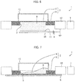
- Fig. 1 is a cross-sectional view illustrating the filling step in a powder film forming method in accordance with Embodiment 1.
- the powder film forming device 1 includes a screen plate 2 (powder filling member).
- Fig. 2 is a cross-sectional view illustrating a configuration of the screen plate 2 used in the filling step.
- the screen plate 2 includes (i) a screen mesh 4 (porous body) and (ii) a screen emulsion part 5 (covering part) provided on one surface of the screen mesh 4. An opening 3 is formed in the screen emulsion part 5.
- the screen plate 2 can be made of typical stainless steel mesh for screen printing.
- the opening 3 of the screen plate 2 can have, for example, a 50 mm ⁇ 50 mm square shape. Note, however, that by changing the shape of the opening 3, it is possible to form a powder film 11 into any form.
- the screen plate 2 of Embodiment 1 is formed so that the screen emulsion part 5 extends (i) in a direction from one surface toward the other surface of the screen mesh 4 and (ii) from the other surface.
- the screen emulsion part 5 is thus formed so as to enter the screen mesh 4 in a direction from the other surface toward the one surface of the screen mesh 4.
- emulsion side the other surface side of the screen mesh 4
- meh side the one surface side of the screen mesh 4
- a thickness t2 of the screen emulsion part 5, by which the screen emulsion part 5 extends from the screen mesh 4 will be referred to as "emulsion thickness”.
- emulsion thickness a thickness of a powder 9, with which the opening 3 of the screen plate 2 can be filled, is adjusted by changing the emulsion thickness t2. This controls a formation amount by which the powder film 11 ( Fig. 3 ) is formed on a substrate 10.
- the volume of the powder 9 can also be adjusted by changing at least one of (i) the screen fabric thickness t1 of the screen mesh 4 and (ii) a mesh size of the screen mesh 4.
- the screen plate 2 is provided so that an axis direction (a vertical direction indicated by the arrow A) of the opening 3 aligns with the direction of gravitational force.
- a rubbing body 15 made of polyurethane sponge is provided on the mesh side of the screen plate 2.
- the rubbing body 15 can be made of rubber, squeegee, brush, or the like.
- the rubbing body 15 moves on the screen mesh 4, so as to rub the powder 9 into the screen mesh 4. This pushes the powder 9 into the opening 3. This allows an entirety of the opening 3 to be uniformly filled with the powder 9.
- a holding plate 6 (holding member), which blocks the opening 3 and is smooth, is provided.
- the powder 9 is provided to the mesh side of the screen plate 2.
- the powder 9, which has been provided to the mesh side of the screen plate 2 is rubbed into the screen mesh 4 by the rubbing body 15 which is moving on the screen mesh 4 of the screen plate 2. This causes the powder 9 to fill the opening 3 against which the smooth holding plate 6 is pressed from the lower side. Subsequently, the holding plate 6 is removed from the opening 3.
- a filling amount of the powder 9 or a formation amount of the powder film 11 can be controlled by (i) a volume of the opening 3 of the screen plate 2 and/or (ii) an amount by which the powder 9 is pushed in (density of the powder).
- a volume of a space filled with the powder 9 is uniquely determined. This (i) allows the powder film 11 to be formed so as to have a desired thickness and (ii) allows a fixed formation amount to be constantly maintained even in a case where film formation is repeated.
- the porous body filled with the powder 9 is not limited to the screen plate 2.
- the porous body can be any of (i) a sieve, (ii) a punching metal, and (iii) a metal plate which is obtained by forming many fine pores in a metal plate.
- the powder film 11 can be formed into any shape by changing (i) a pattern of the screen emulsion part 5 provided to the screen mesh 4 or (ii) positions of the pores formed in the metal plate.
- a powder 9 is provided on the screen mesh 4 of the screen plate 2.
- the screen plate 2 can be, for example, a stainless steel mesh, a polyester mesh, or a nylon mesh.
- a film can be formed with superior film formation accuracy by forming the film by use of electrostatic induction. It is therefore preferable to use, as the screen plate 2, a stainless steel mesh which is suitable for film formation by electrostatic induction.
- the powder film 11 can be formed into any shape by changing a pattern of the opening 3 of the screen plate 2.
- the screen plate 2 it is possible to (i) fill the opening 3 with the powder 9 from the mesh side on which a squeegee is to be scanned during ordinary screen printing or (ii) fill the opening 3 with the powder 9 from the emulsion side.
- the formation amount such as the thickness of the powder film 11 formed, can be controlled by the volume of the opening 3 of the screen plate 2.
- the volume of the opening 3 of the screen plate 2 it is possible to control the volume of the opening 3 by controlling (i) the wire diameter of the screen mesh 4, (ii) the mesh number of the screen mesh 4, and (iii) the emulsion thickness t2.
- the amount of the powder 9 provided in the opening 3 of the screen plate 2 is not particularly limited, provided that the amount is not less than the volume of the opening 3. From the perspective of uniformly filling the opening 3 of the screen plate 2 with the powder 9, the powder 9 is desirably crushed to such an extent that there are no large agglomerated particles.
- the opening 3 of the screen plate 2 is filled with the powder 9 provided on the screen mesh 4 of the screen plate 2. It should be noted that it is important to press the holding plate 6 against the lower side of the opening 3. By thus pressing the holding plate 6, the powder 9, which is filling the opening 3, can be held in the screen plate 2.
- a state of a surface of the powder film 11 after being formed depends on a state of an opening 3-side surface of the holding plate 6. Therefore, in order to form the powder film 11 uniformly, it is desirable to (i) cause the thickness of the holding plate 6 to be uniform and (ii) cause unevenness of the opening 3-side surface of the holding plate 6 to be as little as possible.
- the distribution in thickness of the powder film 11 to be formed can be changed as appropriate by setting a surface-wise distribution in thickness of the holding plate 6.
- the holding plate 6 can be made of, for example, (i) metal such as stainless steel or (ii) resin. However, in view of smoothness, durability, and the like of the surface, metal is desirable.
- the rubbing body 15 can be, for example, (i) a sponge such as a polyurethane sponge, (ii) a squeegee, or (iii) a brush. Then, the rubbing body 15 is scanned across a part of the screen mesh 4, which part is located on the opening 3, so that the powder 9 provided in the screen mesh 4 is pushed into the opening 3. This causes the opening 3 to be filled with the powder 9. In this case, although depending on a surface area of the opening 3, scanning the rubbing body 15 several times completes the process of filling the opening 3 with the powder 9.
- Fig. 3 is a cross-sectional view illustrating the film forming step in the powder film forming method.
- the powder film 11 is to be formed, there is provided an electric potential difference between the screen plate 2 and the substrate 10.
- the powder 9 filling the opening 3 moves from the opening 3 to a printed material 16 positioned on the substrate 10, so that the powder film 11 is formed.
- the screen plate 2 is connected to a negative electrode of the direct current power supply 8.
- the powder 9 filling the opening 3 is negatively charged.
- the substrate 10 is connected to a positive electrode of the direct current power supply 8.
- the powder 9 filling the opening 3 is rubbed from an upper surface of the screen mesh 4. This causes the powder 9 filling the opening 3 to move onto the substrate 10.
- the powder 9 is moved, by electrostatic induction, to the substrate 10 while maintaining the shape thereof, such as the thickness, which the powder 9 had when the powder 9 was filling the opening 3. This causes the powder 9 to be stuck onto the surface of the printed material 16 of the substrate 10.
- the direct current power supply 8 which connects the screen plate 2 and the substrate 10, can (i) connect the screen plate 2 to the positive electrode and (ii) connect the substrate 10 to the negative electrode.
- a distribution in thickness of a powder film 11 to be formed can be changed as appropriate by changing an in-place thickness of a holding plate 6 which blocks an opening 3 during filling of the opening 3.
- a holding plate 6A-side surface of a powder 9 filling the opening 3 has a shape obtained by transferring a state of an opening 3-side surface of the holding plate 6. Therefore, in order to cause a distribution in thickness of the powder film 11 to be uniform, it is ordinarily desirable to (i) cause a distribution in thickness of the holding plate 6, which is pressed against the opening 3, to be uniform and (ii) cause unevenness of the opening 3-side surface of the holding plate 6 to be as little as possible.
- FIG. 4 is a cross-sectional view illustrating the filling step in the powder film forming method in accordance with Embodiment 2.
- (b) of Fig. 4 is a plan view illustrating the holding plate 6A in accordance with Embodiment 2.
- Constituent elements, which are identical to those described in Embodiment 1, will be given the same reference signs. The descriptions of these constituent elements will therefore not be repeated.
- a groove is provided only to a part of the holding plate 6A, which part corresponds to the end part of the powder film 11.
- a groove 17 which has a hollow square shape along an outer peripheral part of the opening 3, is provided in the holding plate 6A. This causes a part of the powder, which part corresponds to the groove 17, to be large in filling amount/thickness when the opening 3 is filled with the powder. Therefore, a part of the powder film 11 to be formed, which part corresponds to the groove 17, to be also large in thickness.
- Changing the shape of the groove 17 allows a powder film 11, which has any thickness distribution, to be formed.
- Fig. 4 shows an example in which a depth of the groove 17 is constant.
- the depth of the groove 17 can change continuously instead of changing in steps.
- Embodiments 1 and 2 each discussed an example in which a film is formed by (i) filling the opening 3 with the powder 9 from the screen mesh 4-side of the screen plate 2 and then (ii) moving the powder 9 from the screen emulsion part 5-side of the opening 3 to the substrate 10.
- the present invention is not limited to such an example.
- it is possible to form a film by (i) filling the opening 3 with the powder 9 from the screen emulsion part 5-side of the screen plate 2 and then (ii) moving the powder 9 from the screen mesh 4-side of the opening 3 to the substrate 10.
- the opening 3 is first filled with the powder 9 from the screen emulsion part 5-side.
- the screen plate 2 is inverted into the state illustrated in Fig. 2 .
- the rubbing body 15 scans at the screen mesh 4-side so as to cause the powder 9 to move to the substrate 10. This method may improve the film formation accuracy of the powder film 11.
- a dry powder which had a particle size (D50) of 4 ⁇ m and a substantially spherical shape, was prepared as a powder 9 to be formed into a film.
- a screen plate 2 for screen printing was prepared as a porous body which was to be filled with the powder 9.
- a stainless steel mesh was used as a screen mesh 4.
- the mesh had a wire diameter of 30 ⁇ m, a screen fabric thickness t1 of 60 pm, a mesh number of 300/inch, and an opening of 55 ⁇ m.
- An opening 3 had a solid pattern with a 50 mm ⁇ 50 mm shape.
- an emulsion thickness was changed as shown in [Table 1] so as to change the volume of the opening 3.
- [Table 1] shows test conditions and evaluation results of Examples 1 through 6 and of Comparative Example 1.
- Example 1 Test conditions Evaluation result Filling step Yes/No Electric field strength (kV/mm) Porous body Rubbing body Screen emulsion thickness ( ⁇ m) Pressing plate thickness distribution Yes/No Single layer formation amount (g) In-place thickness distribution Yes/No variance (%)
- Example 1 Yes 0 Screen plate Sponge 50 No 0.118 No 9.4
- Example 2 Yes 1 Screen plate Sponge 50 No 0.125 No 6.7
- Example 3 Yes 1 Metal mask Sponge 60* No 0.101 No 8.3
- Example 5 Yes 1 Screen plate Squeegee 10 No 0.104 No 6.9
- Example 6 Yes 1 Screen plate Squeegee 50 Yes 0.156 Yes 41.1 Comparative Example 1 No 1 Screen plate Sponge 50 - - Yes 30.7
- Example 5 a metal mask prepared by electroforming was used. The opening had a solid pattern with a 50 mm ⁇ 50 mm shape as in the case of the screen plate 2. The opening was caused to have pores corresponding to a mesh number
- a holding plate 6 which was to be pressed against the opening 3 of the screen plate 2 from the lower side, was prepared.
- a stainless steel plate used as the holding plate 6 had dimensions of 70 mm ⁇ 70 mm, a thickness of 300 ⁇ m, and a flatness of not more than 50 ⁇ m.
- a region having dimensions of 40 mm ⁇ 40 mm likewise had a thickness of 300 ⁇ m and a flatness of not more than 50 ⁇ m.
- an inclination of 6.7 ⁇ m/mm was made from the inner side toward the outer side.
- powder films 11 were formed according to respective test conditions shown in [Table 1].
- a substrate 10 identical to the holding plate 6 was used.
- the powder 9 filling the opening 3 was moved to the substrate 10, so that the powder film 11 was formed.
- Example 5 the formation of was a film was carried out 3 times, so that the powder film 11 including 3 layers was formed.
- Example 5 the formation of a film was carried out 5 times, so that the powder film 11 including 5 layers was formed. Note that in order to calculate a formation amount of single layer, the following were measured: (i) a weight of a stainless steel plate of a printed material 16 before the film formation and (ii) a weight of the stainless steel plate of the printed material 16 after the film formation of the single layer. Subsequently, the powder film 11 thus formed was irradiated with light in a horizontal direction, and the presence/absence of a distribution in in-place thickness of the powder film 11 was checked by visual observation.
- the powder film 11 thus formed was subjected to pressure molding.
- a pressure was 10 ton/cm 2 , and a length of time of the pressuring was 30 seconds.
- four corners and a center part of the powder film 11 were punched out with use of a hand punch having a diameter of 10 mm, and then respective weights of the four corners and the center part thus punched out were measured.
- An average value of the weights thus measured was calculated, and then a range of variance as a deviation from the average value was calculated by the unit %.
- the variances thus calculated are shown in [Table 1].
- Comparative Example 1 a conventional electrostatic film formation, in which no filling step was carried out, was carried out at an electric field strength of 1.0 kV/mm with use of a powder 9, a screen plate 2 and a rubbing body 15 which were similar to those of Example 1.
- the conventional electrostatic film formation is not a method of forming a powder film having more than one layer. A formation amount of single layer was therefore not measured. Pressure molding of the powder film thus formed, punching out with use of a hand punch, and measurement of a weight were carried out as in Examples 1 through 6.
- the film forming step was not divided into (a) a step of filling the opening of the porous body with a powder and (b) a step of causing the powder, with which the opening of the porous body was filled, to move from the opening to a substrate.
- Example 1 the film forming step was divided into (a) a step of filling the opening 3 of the porous body (screen plate 2) with the powder 9 and (b) a step of causing the powder 9 filling the opening 3 of the screen plate 2 to move from the opening 3 to the substrate 10 so as to form the powder film 11. This caused the value of the variance to be reduced to 9.4% which was approximately 1/3 of that of Comparative Example 1.
- Example 2 when the powder 9 filling the opening 3 of the screen plate 2 was moved from the opening 3 to the substrate 10, an electric potential difference was made so as to generate an electric field strength of 1 kV/mm between the screen plate 2 and the substrate 10. This caused the value of the variance to be more reduced to 6.7%.
- Example 3 the powder film 11 was formed with use of a metal mask as the porous body.
- the volume of the pores of the porous body became less than the volume of the opening 3 of the screen plate 2. Consequently, the formation amount of single layer became less than those of Examples 1 and 2.
- the value of the variance was such a good value as not more than 10%. This confirmed that it is possible to use a metal mask other than the screen plate 2 as a porous body.
- Example 4 as a rubbing body 15, a squeegee was used instead of a sponge.
- the value of the variance was such a good value as not more than 10%. This confirmed that it is possible to use a rubbing body 15 which is of any of many types other than a sponge.
- Example 5 the volume of the opening 3 of the screen plate 2 as a porous body was decreased by changing the emulsion thickness of the screen plate 2 from 50 ⁇ m to 10 ⁇ m. As a result, the value of the variance was such a good value as not more than 10%. The formation amount of single layer became less than that of Example 4. This confirmed that it is possible to control the formation amount by controlling the volume of the opening 3 of the screen plate 2.
- Example 6 a distribution in thickness was provided to the holding plate 6 to be pressed against the opening 3 of the screen plate 2. As a result, it was observed that a distribution in in-place thickness occurred to the powder film 11 formed, and the value of the variance was increased. This confirmed that a distribution in in-place thickness of the powder film 11 to be formed can be controlled as appropriate by providing a distribution to the thickness of the holding plate 6.
- the screen plate 2 including the screen mesh 4 (porous body) and the screen emulsion part 5 (covering part) was used.
- the present invention is not limited to such an example. It is unnecessary to provide a covering part, provided that a desired film thickness can be obtained only with use of a porous body.
- a member such as an emulsion part of a screen plate is unnecessary in a case where a porous body to be used is obtained by subjecting only a film formation part of a metal plate to a process of forming fine pores. Note, however, that, in a case where a desired film thickness is large, it is preferable to use a screen plate 2 including the screen mesh 4 (porous body) and the screen emulsion part 5 (covering part).
- a powder provided on a screen plate is rubbed into the screen plate by a rubbing body. Therefore, not an entirety of the powder provided on the screen plate is formed into a film on a printed material.
- a powder provided on the screen plate is divided into (i) a powder remaining on the screen plate without being formed into a film on the printed material and (ii) a powder held by the rubbing body. This poses such a problem that it is difficult to control a thickness of a powder film which is formed by causing, by electrostatic induction, a powder to move from a mesh (pores) of the screen plate to a printed material so as to be stuck on the printed material.
- FIG. 5 is a cross-sectional view illustrating the filling step in a powder film forming method in accordance with Embodiment 4.
- a powder film forming device 1 includes a screen plate 2 (powder filling member) which is provided in a screen frame 12.
- the screen plate 2 includes (i) a screen mesh 4 (porous body) and (ii) a screen emulsion part 5 (covering part) provided on one surface of the screen mesh 4.
- the screen plate 2 is provided so that the screen emulsion part 5 is located at the lower side of the screen mesh 4.
- the screen emulsion part 5 has an opening 3.
- a holding plate 6 (holding member) is provided at the lower side of the screen emulsion part 5 so as to block the opening 3.
- a powder 9 is provided onto the screen mesh 4.
- the powder 9 is, for example, a powder 1 for a JIS test (type 17; heavy calcium carbonate). Note, however, that a powder to be used is not limited to such a powder.
- the powder film forming device 1 includes a vibration exciting member 7 configured to subject the screen plate 2 to vibration excitation.
- the opening 3 of the screen emulsion part 5 of the screen plate 2 has a square shape. Note, however, that a powder film of any shape can be formed by changing the shape of the opening 3.
- the screen mesh 4 has a mesh number of 300/inch, a wire diameter of 30 pm, and an opening size of 55 ⁇ m.
- the screen mesh 4 can be made of a material such as ordinary polyester, ordinary nylon, ordinary stainless steel, or ordinary polyethylene. Note, however, that the mesh number, the wire diameter, the opening size, and the material should be selected according to a powder 9 to be used.
- the screen plate 2 can be a porous body which has fine pores in which the powder 9 can be held.
- Examples of the screen plate 2 encompass a punching metal, a sieve, and a metal plate which has been subjected to microfabrication.
- the powder film forming method in accordance with Embodiment 4 will be described below in the following three steps: (i) a fluidizing step, (ii) a powder filling step (filling step), and (iii) a film forming step.
- the fluidity of the powder 9 can be improved by a method, example of which encompass: (i) enlarging of a particle diameter of the powder 9 (granulation), (ii) causing a particle diameter distribution to be uniform, (iii) causing each particle to be perfectly spherical, and (iv) removing electricity.
- the fluidization process in the fluidizing step can be carried out by any one of these methods, or can be carried out by any combination of these methods.
- the fluidization process is carried out by a dry method. Therefore, the granulation of the particles, making of the uniformity of the particle diameter distribution, and slightly making of perfectly spherical particles are carried out by carrying out compression of a raw material, crushing, and sieving in this order.
- a powder 9 is provided on the screen mesh 4 of the screen plate 2.
- the scattering prevention plate 13 is provided on the screen mesh 4 so as to cover the powder 9 and the opening 3.
- the vibration exciting member 7 applies vibration to the screen plate 2. This causes the powder 9, which is provided on the screen mesh 4, to (i) pass through the screen mesh 4 due to the vibration applied to the screen plate 2 and (ii) fill the opening 3.
- the vibration applied to the screen plate 2 is preferably applied while the holding plate 6 is provided at the lower side of the screen emulsion part 5 so as to cover the opening 3.
- vibration is preferably applied to the screen plate 2 while the screen mesh 4 is provided on the upper side the screen emulsion part 5 (see Fig. 5 ).
- This causes a lower surface of the powder 9, which is filling the opening 3, to be regulated by the holding plate 6 so as to be flat.
- an upper surface of the powder 9, which is filling the opening 3, is regulated by the screen mesh 4 so as to be flat.
- a filling amount of the powder 9, with which the opening 3 is filled, can therefore be precisely controlled by the volume of the opening 3 in the screen plate 2.
- any typical vibration sieving device can be used as the vibration exciting member 7.
- in-plane sieving in which vibration excitation is carried out in a direction along the surface of the screen plate 2
- vibration excitation is carried out in a direction perpendicular to the direction along the surface of the screen plate 2.
- vibration excitation is carried out in a combination of high-frequency vibration and low-frequency vibration.
- a typical in-plane sieving device is used as the vibration exciting member 7 to carry out in-plane sieving while the screen plate 2 is inclined by approximately several degrees with respect to the horizontal direction.
- the opening 3 of the screen plate 2 is completely filled with the powder 9 in approximately 30 seconds. It can be deemed that in a case where ten powder film forming devices 1 are stacked together and subjected to vibration at once, a period of time it takes for each screen plate 2 to be filled with the powder 9 is approximately 3 seconds.
- a film thickness and a powder weight of a powder film 11 to be formed are determined by accuracy with which the opening 3 of the screen plate 2 is filled with the powder 9. Therefore, the powder 9 provided on the screen mesh 4 should, in its entirety, properly fill the opening 3 of the screen plate 2 by optimizing, for example, (i) specifications of the powder 9, (ii) specifications of the screen plate 2, and (iii) vibration conditions.
- the term "lump" means an aggregate formed as a result of the powder 9 rolling over the screen plate 2. In a case where a diameter of the aggregate is larger than the mesh size of the screen mesh 4, the aggregate cannot pass through the screen mesh 4. Consequently, the aggregate becomes an excess powder (i.e., an unwanted powder which cannot fill the opening irrespective of the number of times of vibration).
- Fig. 6 is a cross-sectional view illustrating the film forming step in the powder film forming method.
- the vibration exciting member 7 applies vibration to the screen plate 2 in which the opening 3 is filled with the powder 9
- the powder 9 filling the opening 3 falls. This causes a powder film 11 to be formed on the substrate 10.
- the screen plate 2 is preferably provided so that the screen emulsion part 5 is positioned at the lower side of the screen mesh 4. This allows the powder 9, which is filling the opening 3 of the screen plate 2, to easily fall on the substrate 10 provided below the opening 3.
- the scattering prevention plate 13 can be used as necessary. In order to make it unnecessary to use the scattering prevention plate 13, however, it is preferable to find vibration conditions under which the powder 9 filling the opening 3 of the screen plate 2 is prevented from passing through the screen mesh 4 so as to be scattered upwards.
- the vibration applied to the screen plate 2 in the film forming step can be smaller in vibration exciting force than the vibration applied to the screen plate 2 in the powder filling step.
- the vibration applied in the film forming step varies depending on the specifications of the powder 9 and on the specifications of the screen plate 2, it is necessary to apply ultrasonic vibration, low-frequency vibration, or one-time impact vibration.
- the vibration exciting member 7 merely applies vibration to the screen plate 2 in which the opening 3 is filled with the powder 9
- the powder 9 falls on the substrate 10 provided at the lower side of the screen plate 2.
- the powder 9 is preferably attracted to the substrate 10 by an electrostatic force which is generated between the screen plate 2 and the substrate 10 through providing a direct current power supply 8 that causes an electric potential difference between the screen plate 2 and the substrate 10.
- a distance and an electric potential difference between the screen plate 2 and the substrate 10 are approximately 10 mm and 8 kV, respectively.
- the present invention is not limited to such an example. This is because proper conditions vary depending on the specifications of the powder 9 and on the specifications of the screen plate 2.
- Fig. 7 is a cross-sectional view illustrating a filling step in a powder film forming method in accordance with Embodiment 5.
- Constituent elements which are identical to those described with reference to Fig. 5 , will be given the same reference signs. The detailed descriptions of these constituent elements will therefore not be repeated.
- the filling step differs from the filling step in the powder film forming method describe with reference to Fig. 5 in that the screen plate 2 illustrated in Fig. 5 is turned upside down so that the screen mesh 4 is located below the screen emulsion part 5.
- the screen plate 2 is preferably subjected to vibration excitation while a holding plate 6 is provided at the lower side of the screen mesh 4.
- a holding plate 6 is provided at the lower side of the screen mesh 4.
- the screen mesh 4 can reliably hold the powder 9
- the powder 9 is excessively scattered as a result of the vibration, it is possible to prevent the scattering of the powder 9 by providing a scattering prevention plate 13 so that the scattering prevention plate 13 covers the powder 9.
- the screen mesh 4 is provided on the upper side of the screen emulsion part 5 as illustrated in Fig. 5 .
- the powder 9 needs to pass through the screen mesh 4. Therefore, there may be a case where the opening 3 cannot be filled favorably, depending on the powder 9.
- the screen plate 2 is inverted and the opening 3 is filled with the powder 9. This allows the opening 3 to be filled favorably with any of most types of powders 9.
- the screen plate 2 is thus inverted, it is necessary to carry out the following after the opening 3 is filled with the powder 9. That is, it is necessary to cause an upper surface of the powder 9 filling the opening 3 to be as flat as possible by removing, through leveling the powder 9 filling the opening 3, an excess powder which is remaining without filling the opening 3.
- Fig. 8 is a cross-sectional view illustrating a powder film forming method in accordance with Comparative Example.
- the powder film forming method in accordance with Comparative Example is a typical electrostatic screen printing method.
- a powder 9 is rubbed, with use of a rubbing member 21, into a screen 22 which is connected to a negative electrode of a direct current power supply 8 or to ground (earth).
- This causes the powder 9 to come into contact with the screen 22 so as to be charged or grounded.
- the powder 9 thus charged or grounded is, due to electrostatic induction, stuck to a printed material 16 on a substrate 10 which is connected to a positive electrode of the direct current power supply 8.
- This causes a powder film 11 to be formed.
- the screen 22 is connected to the positive electrode of the direct current power supply 8 and (ii) the substrate 10 is connected to the positive electrode of the direct current power supply 8.
- particles of the powder 9, which are in contact with the screen 22 are charged or grounded so as to be firmly stuck to the printed material 16.
- neither particles, which are not in contact with the screen 22, nor a group of particles, which are assembled on the screen 22 so as to be a bulk are charged or grounded favorably.
- Such particles of the powder 9, which are not charged or grounded may be subjected to rubbed against the rubbing member 21 and/or screen 22 so as to be frictionally charged, so that electric charge of the powder 9 may become non-uniform. This unfortunately causes the particles and the particle group, which are not charged favorably, to result in impairment of film formation accuracy of a powder film 11.
- a powder film is formed on the substrate 10 by causing the powder 9 filling the opening 3 of the screen plate 2 to vibrate so as to move to the substrate 10. Therefore, the particles of the powder 9 do not necessarily need to be charged.
- the particles of the powder 9 in the screen mesh 4, which are charged or grounded are charged or grounded directly by the screen mesh 4 or via other particles of the powder 9 which are charged or grounded. Therefore, impairment of the film formation accuracy of the powder film 11, which occurs due to the particles or the particle group which are not charged favorably, is prevented from occurring.
- a powder film is formed on the substrate 10 by causing the powder 9 filling the opening 3 of the screen plate 2 to vibrate so as to move to the substrate 10. Therefore, the particles of the powder 9 do not necessarily need to be charged. Therefore, the failure of the formation of the powder film 11, which occurs because the mesh (pores) of the screen 22 is clogged with the particles or the particle group, is prevented from occurring.
- a powder film is formed on the substrate 10 by causing the powder 9 filling the opening 3 of the screen plate 2 to vibrate so as to move to the substrate 10. This makes it unnecessary to cause all of powder particles to be charged favorably by coming into contact with the screen mesh. It is therefore possible to shorten a period of time it takes to form the powder film 11.
- Table 2 shows the results of film formation in Comparative Example and Embodiment 4, each with the aim of forming a film having dimensions of 100 mm ⁇ 100 mm and a thickness of 100 ⁇ m.
- Embodiment 4 brings about the following advantages: (i) there is no risk of contamination due to abrasion or the like by the rubbing member 21, (ii) a period of time for film formation is shorter, and (iii) it is easy to control the thickness of a film to be formed and control the weight of a powder. This allows a large amount of powder film to be stably formed in a short period of time.
- the screen plate 2 including the screen mesh 4 (porous body) and the screen emulsion part 5 (covering part) was used.
- the present invention is not limited to such an example. It is unnecessary to provide a covering part, provided that a desired film thickness can be obtained only with use of a porous body.
- a member such as an emulsion part of a screen plate is unnecessary in a case where a porous body to be used is obtained by subjecting only a film formation part of a metal plate to a process of forming fine pores. Note, however, that, in a case where a desired film thickness is large, it is preferable to use a screen plate 2 including the screen mesh 4 (porous body) and the screen emulsion part 5 (covering part).
- the rubbing body such as a sponge moves on a powder which has been provided on the screen plate.
- This causes the powder to pass through the screen mesh and the opening of the screen plate so as to be applied to the substrate, so that a powder film is formed. Therefore, uneven formation of a powder film occurs due to (i) a state in which the powder is dispersed on the screen plate and (ii) a track in which the rubbing body moves on the screen plate.
- a conventional electrostatic screen printing method is improved so as to be able to form, in a short period of time, a thin film of a powder, a thickness of which thin film is more uniform.
- Embodiment 6 includes: a providing step of providing a crushed powder at a lower side of a screen plate having a porous body; a filling step of filling, by an electrostatic force, an opening of the screen plate with the powder provided below the screen plate; and a film forming step of forming a powder film by causing, by an electrostatic force, the powder to move from the opening of the screen plate, which is filled with the powder, to a substrate so that the powder is stuck onto the substrate.
- the principle of an electrostatic force is used also in the filling step so as to fill the opening of the screen plate with a powder.
- the porous body can be any of (i) a screen mesh, (ii) a sieve, (iii) a punching metal, and (iv) a member which is obtained by forming many fine pores in any of other metal plates.
- a powder film of any shape can be formed by changing a factor(s), examples of which encompass (i) the shape of any of these members and (ii) positions of the pores to be formed.
- Fig. 9 is a cross-sectional view illustrating the providing step in the powder film forming method in accordance with Embodiment 6.
- a powder 9 is crushed and dispersed in a providing container 14.
- the powder 9 is not particularly limited, provided that the powder 9 is crushed to such an extent that particles of the powder 9 are not aggregated together.
- Fig. 9 there is a method in which the powder 9 is crushed with use of a sieve 17 provided at the upper side of the providing container 14, so that the powder 9 is provided into the providing container 14.
- the powder 9 is sieved through the sieve 17 so as to be dropped and dispersed into the providing container 14 having a bottom surface which is made of an electrically conducive material such as metal.
- the powder 9 it is unnecessary for the powder 9 to be exactly uniformly dispersed into the providing container 14, provided that the powder 9 in an amount larger than the volume of an opening 3 of a screen plate 2 illustrated in Figs. 11 and 12 in the filling step (described later) is dispersed all over the bottom surface of the providing container 14 so that the bottom surface of the providing container 14 is not exposed.
- the method of crushing the powder 9 so as to provide the powder 9 into the providing container 14 is not limited to a method in which the sieve 17 is used.
- Examples of the method encompass generally conceivable methods such as (i) a method in which the powder 9 is provided through ultrasonic sieving, (ii) a method in which the powder 9 is provided through spray coating, (iii) a method in which the powder 9 is provided with use of a coater feeder, and (iv) a combination of these methods.
- the powder 9 can be crushed by use of air stream or centrifugal force.
- the providing container 14 can be a flat plate.
- the powder 9 can be a dry powder having a particle size (D50) of 5 ⁇ m. Note, however, that the powder 9 used in the powder film forming method in accordance with Embodiment 6 is not limited to such an example.
- the sieve 17 can be a sieve having (i) an inner diameter ⁇ of 75 of JIS Z-8801 and (ii) a mesh size of 500 ⁇ m. Note, however, that the sieve 17 is not limited to such an example.
- the crushing method is not limited to a method in which the sieve 17 is used. It is necessary to select a proper crushing method according to the powder 9.
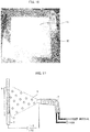
- Fig. 10 is a photograph showing the providing container 14 in which the powder 9 is dispersed in the providing step.
- the providing container 14 was a flat plate which had a 70 mm ⁇ 70 mm square shape and which was made of SUS (stainless steel).
- the powder 9 was dispersed onto the SUS flat plate while the powder 9 was being crushed by the sieve 17. It is unnecessary for the powder 9 thus crushed to be exactly uniformly dispersed, provided that the powder 9 dispersed in such an amount that the bottom surface of the SUS flat plate is not exposed (0.50 g to 0.55 g).
- FIG. 11 is a cross-sectional view illustrating the filling step in the powder film forming method.
- a powder film forming device 1 includes the screen plate 2 (powder filling member) having the opening 3 which is to be filled with the powder 9.
- Fig. 12 is a cross-sectional view illustrating a configuration of the screen plate 2 used in the filling step.
- the screen plate 2 includes (i) a screen mesh 4 (porous body) and (ii) a screen emulsion part 5 (covering part) provided on one surface of the screen mesh 4.
- the opening 3 is formed in the screen emulsion part 5.
- the screen plate 2 can be made of typical stainless steel mesh for screen printing.
- the opening 3 of the screen plate 2 can have a 50 mm ⁇ 50 mm square shape. Note, however, that by changing the shape of the opening 3, it is possible to form a powder film 11 into any form.
- the screen plate 2 of Embodiment 6 is formed so that the screen emulsion part 5 extends (i) in a direction from one surface toward the other surface of the screen mesh 4 and (ii) from the other surface.
- the other surface side of the screen mesh 4 will be referred to as "emulsion side”
- the one surface side of the screen mesh 4 will be referred to as "mesh side”.
- a thickness t2 of the screen emulsion part 5, by which the screen emulsion part 5 extends from the screen mesh 4, will be referred to as "emulsion thickness”.
- the volume of the powder 9, with which the opening 3 of the screen plate 2 can be filled is adjusted by changing the emulsion thickness t2. This controls a formation amount by which the powder film 11 ( Fig. 15 ) is formed on a substrate 10. Note, however, that the volume of the powder 9 can also be adjusted by changing at least one of (i) the screen fabric thickness t1 of the screen mesh 4 and (ii) a mesh size of the screen mesh 4.
- the providing container 14 in which the powder 9 is dispersed, is provided below the screen plate 2.
- a holding plate 6 holding member for blocking the upper surface side of the opening 3 is provided on the screen plate 2.
- a positive electrode of a direct current power supply 8 power supply
- a negative electrode connected to the screen plate 2 is connected the providing container 14.
- the powder 9 on the providing container 14 is positively charged by the positive electrode of the direct current power supply 8. Then, the powder 9, which is positively charged, is attracted, by electrostatic induction, to the screen plate 2 which is negatively charged by the negative electrode of the direct current power supply 8. Then, the opening 3 of the screen plate 2 is filled with the powder 9.
- positive and negative of the direct current power supply 8 can be inverted so as to (i) connect the positive electrode of the direct current power supply 8 to the screen plate 2 and (ii) connect the negative electrode to the providing container 14.
- An electric field strength (electric potential difference, distance) between the providing container 14 and the screen plate 2 is necessary for attracting the powder 9, by electrostatic induction, from the providing container 14 to the screen plate 2.
- the electric field strength varies depending on the type of the powder 9. Therefore, the electric field strength (electric potential difference, distance) should be set to a proper value according to each type of the powder 9.
- FIG. 13 is a photograph in which the screen plate 2 after the filling in the filling step is viewed from the emulsion side.
- FIG. 13 is a photograph in which the screen plate 2 is viewed from the mesh side.
- the providing container 14 which is an SUS plate onto which the powder 9 is provided
- the screen plate 2 is provided below the screen plate 2 on which the holding plate 6 (which is an SUS plate) is provided.
- the screen plate 2 is provided so that the mesh side and the emulsion side face upwards and downwards, respectively.
- the emulsion thickness t2 of the screen plate 2 is set to 50 ⁇ m.
- the holding plate 6 is provided on the emulsion side of the screen plate 2.
- a distance of 7 mm is set between (i) the screen plate 2 and (ii) the providing container 14 (which is an SUS plate onto which the powder 9 is provided).
- the screen plate 2 is grounded.
- a voltage of 8 kV is applied to the providing container 14 which is an SUS plate.
- the strength of the electric field between the screen plate 2 and the providing container 14 which is an SUS plate is 1.14 kV/mm. This causes the powder 9 to be moved, by an electrostatic force based on the electric field strength, from the providing container 14 (which is an SUS plate) to the opening 3 formed in the screen emulsion part 5 of the screen plate 2 so as to fill the opening 3 (see Figs. 11 and 13 ).
- the opening 3 can be filled with the powder 9 by, with use of an electrostatic spray discussed in Embodiment 7 (described later), spraying the opening 3, to which the voltage is applied, with the powder 9 which is charged.
- the present invention is not limited to such an example. Alternatively, it is possible to fill the opening 3 with the powder 9 from the upper surface side of the opening 3.
- Fig. 14 is a cross-sectional view illustrating a state immediately before rubbing in the film forming step in the powder film forming method.
- Fig. 15 is a cross-sectional view illustrating how the powder 9 is stuck to the printed material 16 by electrostatic induction in the film forming step.
- the screen plate 2 in which the opening 3 is filled with the powder 9 in the filling step, is connected to the negative electrode of the direct current power supply 8. This causes the powder 9 filling the opening 3 to be negatively charged by contact charging. Then, the substrate 10, on which the printed material 16 is provided, is connected to the positive electrode of the direct current power supply 8. Then, the powder 9 filling the opening 3 of the screen plate 2 is rubbed off from the opening 3 of the screen plate 2 with use of the rubbing body 15 which moves on the screen plate 2.
- the powder 9 is moved, by electrostatic induction, from the opening 3 to the printed material 16 so as to be stuck to the printed material 16, while the powder 9 maintains its thickness the powder 9 had when the powder 9 was filling the opening 3.
- This causes a powder film 11 to be formed.
- positive and negative of the direct current power supply 8 can be inverted so as to (i) connect the positive electrode of the direct current power supply 8 to the screen plate 2 and (ii) connect the negative electrode to the providing container 14.
- a greater electric field strength (electric potential difference) between the printed material 16 and the screen plate 2 causes the powder 9 to be stuck more firmly to the printed material 16. This makes it possible to cause a density of a powder film 11 to be higher by increasing the electric field strength.
- the electric field strength (electric potential difference, distance) between the printed material 16 and the screen plate 2 is necessary for attracting the powder 9, by electrostatic induction, from the screen plate 2 to the printed material 16. Note, however, that as in the filling step described earlier, the electric field strength varies depending on a charging property or the like of the powder 9. Therefore, the electric field strength (electric potential difference, distance) should be set to a proper value according to the charging property or the like of the powder 9.
- Voltages applied in the filling step and in the film forming step can be applied by a completely identical method.
- the application of a voltage can be carried out by (i) connecting the screen plate 2 to earth (GND) (i.e., grounding the screen plate 2) or applying a negative voltage to the screen plate 2 or (ii) applying a positive voltage to the substrate 10 or to the providing container 14.
- GND earth
- the application of a voltage can be carried out by (i) connecting the screen plate 2 to earth (GND) (i.e., grounding the screen plate 2) or applying a negative voltage to the screen plate 2 or (ii) applying a positive voltage to the substrate 10 or to the providing container 14.
- GND earth
- positive and negative of the direct current power supply 8 can be inverted so as to (i) connect the positive electrode of the direct current power supply 8 to the screen plate 2 and (ii) connect the negative electrode to the providing container 14.
- the formation of an electrostatic field between the screen plate 2 and the substrate 10 should be all it takes to cause, the powder 9 filling the opening 3 to be attracted, by an electrostatic force, to the substrate 10.
- the following phenomenon is conceivable. That is, the powder 9 filling the opening 3 is not necessarily moved favorably to the substrate 10 only by an electrostatic force because a force by which the powder 9 is stuck to the screen plate 2 is greater than the electrostatic force applied to the powder 9.
- Fig. 16 is a photograph showing a powder film 11 which has been formed on the printed material 16 in the film forming step.
- the printed material 16 which has a 70 mm ⁇ 70 mm square shape and which is an SUS plate, is provided below the screen plate 2 in which the opening 3 is filled with the powder 9.
- the screen plate 2 is inverted from the orientation thereof in the filling step, and is provided so that the emulsion side is below the mesh side.
- a distance between the screen plate 2 and the printed material 16 (SUS plate) is set to 6 mm.
- the screen plate 2 is connected to earth (i.e., grounded).
- To the printed material 16 which is an SUS plate a voltage of 8 kV is applied.
- An electric field strength between the screen plate 2 and the printed material 16 is 1.33 kV/mm.
- the rubbing body 15 made of sponge rubs on the screen mesh 4 of the screen plate 2 several times so as to cause the powder 9 filling the opening 3 to move to the printed material 16 (SUS plate).
- the rubbing body 15 can be made of a material other than sponge. Examples of such a material encompass rubber, squeegee, and brush.
- Table 3 shows relationships between amounts of powders 9 provided and corresponding formation amounts of powder films 11 formed in eight respective tests conducted under conditions similar to those described above.
- Test No. 1 3 4 5 6 7 8 Ave STD STD (%) Providing amount 0.515 g 0.512 g 0.507 g 0.503 g 0.525 g 0.531 g 0.529 g 0.5174 g 0.0102 g 2.0% Formation amount 0.128 g 0.120 g 0.124 g 0.123 g 0.125 g 0.132 g 0.132 g 0.1263 g 0.0042 g 3.4%
- a larger volume of the opening 3 formed in the screen plate 2 allows for (i) a larger filling amount of powder 9 to fill the opening 3 or (ii) a larger formation amount of powder film 11 to be formed from the powder 9 filling the opening 3.
- the filling amount or the formation amount can be controlled by (i) the thickness of the screen emulsion part 5 of the screen plate 2 and (ii) the mesh size of the screen mesh 4.
- Embodiment 6 it is also possible to further form a film so that the film is stacked on a powder film 11 formed on the printed material 16. Therefore, the formation amount of powder films can be controlled by forming films any number of times.
- a powder film of a different type can be formed on a powder film 11 formed on the printed material 16. This makes it possible to form a thin film in which a plurality of powder films of different types are stacked.
- Fig. 17 is a cross-sectional view illustrating the filling step in a powder film forming method in accordance with Embodiment 7.
- the providing container 14, in which a powder 9 is dispersed is provided at the lower side of the opening 3 of the screen plate 2, and the powder 9 thus dispersed in the providing container 14 is charged by generating an electric potential difference between the screen plate 2 and the providing container 14. This causes the opening 3 to be filled with the powder 9 thus charged.
- the present invention is not limited to such an example.
- An opening 3 can be filled with a powder 9, which is charged, by spraying the opening 3 with the powder 9 with use of an electrostatic spray 17. To the opening 3, a voltage can be applied.
- the electrostatic spray 17 is provided so as to face the opening 3 of a screen plate 2. Then, the electrostatic spray 17 is connected to a positive electrode of a direct current power supply 8. The screen plate 2 is connected to a negative electrode of the direct current power supply 8. To the electrostatic spray 17, the powder 9 and air are provided.
- the powder 9, which has been thus provided to the electrostatic spray 17, is positively charged. This causes the powder 9 to be sprayed by air from the electrostatic spray 17 toward the opening 3 of the screen plate 2 which is negatively charged. Then, the opening 3 is filled with the powder 9.
- the electrostatic spray 17 can fill the opening 3 of the screen plate 2 with the powder 9 from the lower side of the opening 3.
- the electrostatic spray 17 can fill the opening 3 with the powder 9 from the upper side of the opening 3.
- Fig. 17 shows an example in which the opening 3 is filled with the powder 9 from the lower side of the opening 3.
- the screen plate 2 and the electrostatic spray 17 are connected to each other via the direct current power supply 8. This generates an electric potential difference between the screen plate 2 and the electrostatic spray 17 in the filling step.
- the present invention is not limited to such an example.
- the opening 3 can be physically sprayed with the powder 9 which is charged. It is not necessarily necessary to generate an electric potential difference between the screen plate 2 and the electrostatic spray 17.
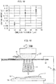
- Fig. 18 is a graph showing a relationship between an emulsion thickness and a coating amount when a powder film forming method in accordance with Embodiment 8 is carried out.
- comparisons were made between different formation amounts of powder films 11 formed by a method similar to the method of Embodiment 6, under the following respective three conditions: (i) the emulsion thickness t2 of a screen plate 2 was 50 ⁇ m, (ii) the emulsion thickness t2 of a screen plate 2 was 10 pm, and (iii) the emulsion thickness t2 of a screen plate 2 was 30 ⁇ m.
- the horizontal axis indicates the emulsion thickness t2 of the screen plate 2, and the vertical axis indicates the formation amount (coating amount) of the powder film 11.
- Each of the black circles in Fig. 18 indicates an average value of formation amounts corresponding to emulsion thicknesses indicated by the corresponding white circles. The results reveal that a greater emulsion thickness t2 (volume of the opening 3) of the screen plate 2 leads to a greater formation amount (coating amount) of a powder film 11.
- Embodiment 8 it is possible to control a formation amount (coating amount) of a powder film 11 by adjusting the emulsion thickness t2 of the screen plate 2.
- Fig. 19 is a cross-sectional view illustrating a powder film forming method in accordance with Comparative Example.
- the powder film forming method in accordance with Comparative Example is a typical electrostatic screen printing method.
- a powder 9 is rubbed, with use of a rubbing body 21, into a screen 22 which is connected to a negative electrode of a direct current power supply 8. This causes the powder 9 to come into contact with the screen 22 so as to be charged.
- the powder 9 thus charged is, due to electrostatic induction, stuck to a printed material 16 on a substrate 10 which is connected to a positive electrode of the direct current power supply 8. This causes a powder film 11 to be formed.
- the screen 22 is connected to the positive electrode of the direct current power supply 8 and (ii) the substrate 10 is connected to the negative electrode of the direct current power supply 8.
- the powder 9 may be retained in a certain part of the screen 22, depending on (i) a state in which the powder 9 is dispersed on the screen 22 and (ii) a manner in which the rubbing body 21 for rubbing the powder 9 into the screen 22 moves on the screen 22. Then, a greater amount of powder 9 retained leads to a greater amount of powder 9 falling below the screen 22. This unfortunately leads to an uneven thickness of a powder film 11 to be formed on the printed material 16.
- a smooth state of the powder 9 filling the opening 3 of the screen plate 2 is reflected in a powder film 11 to be formed on the substrate 10. This allows a thin film having a uniform thickness to be formed without being affected by (i) the state in which the powder 9 is dispersed or (ii) the manner in which the rubbing body 21 moves.
- a target to be rubbed by the rubbing body 15 is a powder 9 which is filling the opening 3 of the screen plate 2. Therefore, the powder 9 filling the opening 3 can be caused to fall onto the substrate 10 merely by causing the rubbing body 15 to rub on the screen plate 2 several times.
- This in comparison with Comparative Example, allows for (i) a considerable reduction in the period of time for formation of a film and (ii) a decrease in amount of contamination which occurs due to the abrasion of the rubbing body 21.
- the powder 9 is, by an electrostatic force, attracted to the opening 3 of the screen plate 2 so as to fill the opening 3 without contact. Therefore, contamination into the powder 9 filling the opening 3, which contamination occurs because of the abrasion of the rubbing body 21, is prevented from occurring.
- a period of time for filling the opening 3 with the powder 9 by an electrostatic force is such a short period as approximately several seconds. This prevents an entire period of time for formation of a film from becoming long even in a case where the process is divided into the filling step and the film forming step.
- Embodiments 6 through 8 are each carried out so that, while one surface-side of the opening 3 of the screen plate 2 is blocked by the holding plate 6 which is smooth, a powder 9 is attracted by an electrostatic force to the other surface-side of the opening 3 of the screen plate 2 so as to fill the opening 3. Then, the opening 3 is detached from the holding plate 6, and the powder 9 filling the opening 3 is moved onto the printed material 16 by an electrostatic force and by the rubbing body 15. This allows a powder film 11 having a uniform thickness to be formed. In particular, an electrostatic force is used for filling the opening 3 of the screen plate 2 with the powder 9.
- the emulsion thickness t2 of the screen plate 2 used for forming the powder film in accordance with Embodiment 7 was 10 ⁇ m. For pressure-molding a powder film, it is necessary for the powder film to have a thickness to a certain extent.
- the period of time measured in each step excludes a period of time required for preliminary preparation such as (i) measuring the weight of a powder 9 and (ii) arrangement of the providing container 14.
- a period of time from the start of the dispersion with use of the sieve 17 until the end of the dispersion was measured.
- a period of time from the start of the application of voltage until the end of the filling was measured.
- a period of time from the start of the application of voltage until the end of the film formation was measured. Table 5 shows the results of the measurement.
- Embodiment 1 Conventional method Providing step (providing material) 15 sec 5 sec Filling step 1 sec 0 sec Film forming step 5 sec 90 sec Total 21 sec 95 sec The results of the measurement confirmed that in comparison with Comparative Example, Embodiment 6 shortened a total amount of time required for forming a single film, from 95 seconds to 21 seconds (i.e., by 74 seconds).
- takt time for building a production line i.e., a period of time required for a step for which it took the longest period of time among all the steps
- takt time was (i) 15 seconds in the case of the electrostatic filling method of Embodiment 6, which was required for the providing step and (ii) 90 seconds in the case of Comparative Example, which was required for the film forming step.
- Comparative Example which was required for the film forming step.
- Embodiment 6 shortened the takt time by 75 seconds.
- the providing step in accordance with Embodiment 6, the takt time can be further shortened by applying a dispersion method other than the dispersion method in which the sieve 17 is used.
- the screen plate 2 including the screen mesh 4 (porous body) and the screen emulsion part 5 (covering part) was used.
- the present invention is not limited to such an example. It is unnecessary to provide a covering part, provided that a desired film thickness can be obtained only with use of a porous body.
- a member such as an emulsion part of a screen plate is unnecessary in a case where a porous body to be used is obtained by subjecting only a film formation part of a metal plate to a process of forming fine pores. Note, however, that, in a case where a desired film thickness is large, it is preferable to use a screen plate 2 including the screen mesh 4 (porous body) and the screen emulsion part 5 (covering part).
- a powder film forming method in accordance with an embodiment is a method of forming a powder film, including the steps of: (a) filling an opening 3 with a powder 9, the opening 3 being formed in a powder filling member (screen plate 2); and (b) forming the powder film 11 by generating an electric potential difference between the powder filling member (screen plate 2) and a substrate 10 so as to cause the powder 9, which is filling the opening 3, to move to the substrate 10.
- the opening of the powder filling member is filled, by the rubbing body, with the powder having a fixed thickness. Then, due to an electric potential difference between the powder filling member and the substrate, the powder moves to the substrate, so as to form a powder film having the fixed thickness. This allows a powder film to be formed with good film thickness accuracy.
- the powder film forming method is preferably arranged so that in the step (a), the powder 9 is rubbed by a rubbing body 15 so as to fill the opening 3.
- the powder film forming method is preferably arranged so that in the step (a), the powder 9 is vibrated so as to fill the opening 3.
- the powder film forming method is preferably arranged so that in the step (a), the powder 9 to fill the opening 3 is charged.
- the powder film forming method is preferably arranged so that in the step (a), the powder 9, which is charged, is caused to fill the powder filling member (screen plate 2) by spraying with use of an electrostatic spray 17.
- the powder film forming method is preferably arranged so that in the step (b), the powder 9 is rubbed by a rubbing body 15 so as to move to the substrate 10.
- the powder film forming method is preferably arranged so that in the step (b), the powder 9 is vibrated so as to move to the substrate 10.
- the powder film forming method is preferably arranged so that: the powder filling member (screen plate 2) includes a porous body (screen mesh 4) and a covering part (screen emulsion part 5) provided on one surface of the porous body (screen mesh 4); the covering part (screen emulsion part 5) has the opening 3; and in the step (b), the covering part (screen emulsion part 5) is provided on a side facing the substrate 10.
- a powder film forming device 1 in accordance with an embodiment includes: a powder filling member (screen plate 2) having an opening 3 to be filled with a powder 9; a rubbing body 15 configured to rub the powder 9 into the opening 3 from one end side of the opening 3 so as to fill the opening 3 with the powder 9; and a power supply (direct current power supply 8) configured to generate an electric potential difference between the powder filling member (screen plate 2) and a substrate 10 so as to cause the powder 9, which is filling the opening 3, to move to the substrate 10.
- a powder filling member screen plate 2 having an opening 3 to be filled with a powder 9
- a rubbing body 15 configured to rub the powder 9 into the opening 3 from one end side of the opening 3 so as to fill the opening 3 with the powder 9
- a power supply direct current power supply 8 configured to generate an electric potential difference between the powder filling member (screen plate 2) and a substrate 10 so as to cause the powder 9, which is filling the opening 3, to move to the substrate 10.
- the powder film forming device 1 is preferably arranged so as to further include: a vibration exciting section (vibration exciting member 7) configured to subject the powder filling member (screen plate 2) to vibration excitation.
- a vibration exciting section vibration exciting member 7 configured to subject the powder filling member (screen plate 2) to vibration excitation.
- the powder film forming device 1 is preferably arranged so as to further include: an electrostatic spray 17 configured to fill the opening 3 with the powder 9.
- a powder film forming method in accordance with an embodiment is a method of forming a powder film, including the steps of: (a) filling an opening 3 with a powder 9 by vibrating the powder 9, the opening 3 being formed in a powder filling member (screen plate 2); and (b) forming the powder film 11 by causing the powder 9, which is filling the opening 3, to move to the substrate 10.
- the powder film forming method is preferably arranged so that in the step (b), the powder 9 is rubbed by a rubbing body 15 so as to move to the substrate 10.
- the powder film forming method is preferably arranged so that in the step (b), the powder 9 is vibrated so as to move to the substrate 10.
- the powder film forming method is preferably arranged so that: the powder filling member (screen plate 2) includes a porous body (screen mesh 4) and a covering part (screen emulsion part 5) provided on one surface of the porous body (screen mesh 4); the covering part (screen emulsion part 5) has the opening 3; and in the step (b), the covering part (screen emulsion part 5) is provided on a side facing the substrate 10.
- the powder film forming method in accordance with Embodiment 1 includes the steps of: (a) filling, through rubbing by the rubbing body 15, an opening 3 with a powder 9, the opening 3 being formed in a powder filling member (screen plate 2); and (b) forming the powder film 11, on the substrate 10, by generating an electric potential difference between the powder filling member (screen plate 2) and a substrate 10 so as to cause the powder 9, which is filling the opening 3, to move to the substrate 10.
- the opening of the powder filling member is filled, by the rubbing body, with the powder having a fixed thickness. Then, the powder moves to the substrate, so as to form a powder film having the fixed thickness. This allows a powder film to be formed with good film thickness accuracy.
- the powder film forming method is preferably arranged so that: in the step (a), (i) the holding member (holding plate 6) for blocking the opening 3 is provided on the lower side of the opening 3, (ii) the opening 3 is filled with the powder 9 from the upper side, and then (iii) the holding member (holding plate 6) is removed; and in the step (b), the substrate 10 is provided below the opening 3, and the powder 9 filling the opening 3 is moved from the lower side of the opening 3 to the substrate 10.
- the holding member for blocking the opening is provided at the lower side of the opening, and the opening is filled with the powder from the upper side.
- the powder film forming method is preferably arranged so that: the powder filling member (screen plate 2) includes a porous body (screen mesh 4) and a covering part (screen emulsion part 5) provided on one surface side of the porous body (screen mesh 4); and the covering part (screen emulsion part 5) has the opening 3.
- a typical screen plate can be used as the powder filling member.
- the powder film forming method can be arranged so that: the power film 11 is formed on the substrate 10 by (i) filling the opening 3 with the powder 9 from the covering part (screen emulsion part 5) side of the powder filling member (screen plate 2) which is provided so that the covering part (screen emulsion part 5) is positioned on the upper side of the porous body (screen mesh 4), (ii) inverting the powder filling member (screen plate 2), and (iii) causing the powder 9, which is filling the opening 3, to move from the covering part (screen emulsion part 5) side to the substrate 10.
- the powder film forming device in accordance with Embodiment 1 includes: the powder filling member (screen plate 2) in which the opening 3 to be filled with the powder 9 is formed; the rubbing body 15 configured to rub the powder 9 into the one end side of the opening 3 so as to fill the opening 3 with the powder 9; the holding member (holding plate 6) provided so as to be able to block the other end side of the opening 3; and the power supply (direct current power supply 8) configured to generate an electric potential difference between the powder filling member (screen plate 2) and the substrate 10 in order to form a powder film 11 on the substrate 10 by causing the powder 9, which is filling the opening 3, to move to the substrate 10.
- the powder film forming method in accordance with each of Embodiments 4 and 5 is a method of forming a powder film, including the steps of: (a) filling an opening 3 with a powder 9 by vibrating the powder 9, the opening 3 being formed in a powder filling member (screen plate 2); and (b) forming, on a substrate 10, the powder film 11 by causing the powder 9, which is filling the opening 3, to move to the substrate 10.
- the powder film 11 is formed on the substrate 10 by causing the powder 9, which is filling the opening 3 of the powder filling member (screen plate 2), to move to the substrate 10.
- This causes a smooth thickness state of the powder 9, which is filling the opening 3, to be reflected in a powder film 11 to be formed. Therefore, in comparison with the conventional configuration in which a powder on the screen 22 passes through the opening 3 to move to the substrate 10 as a result of the rubbing member 21 moving on the screen 22, it is possible to cause the thickness of the powder film 11, which is to be formed on the substrate 10, to be closer to being uniform.
- the powder film forming method can be arranged so that in the step (b), the powder 9 filling the opening 3 is vibrated so as to move to the substrate 10.
- the powder film forming method can be arranged so that in the step (b), the powder 9 is caused to move to the substrate 10 by applying a voltage between the powder filling member (screen plate 2) and the substrate 10.
- the powder film forming method can be arranged so that: the powder filling member (screen plate 2) includes a porous body (screen mesh 4) and a covering part (screen emulsion part 5) provided on one surface of the porous body (screen mesh 4); and the covering part (screen emulsion part 5) has the opening 3.
- the powder film forming method in accordance with Embodiment 4 can be arranged so that: in the step (a), the opening 3 is filled with the powder 9 via the porous body (screen mesh 4) while (i) the covering part (screen emulsion part 5) is provided at a vertically lower side and (ii) the holding member (holding plate 6) is provided so as to block a vertically lower side of the opening 3 of the covering part (screen emulsion part 5).
- the bottom surface of the powder 9 filling the opening 3 is caused by the holding plate 6 to be flat and (ii) the upper surface of the powder 9 is caused by the screen mesh 4 to be flat. This allows the filling amount of the powder 9 to be suitably controlled by the volume of the opening 3.
- the powder film forming method in accordance with each of Embodiments 4 and 5 can be arranged so that before the step (a), at least one of the following steps is carried out: (i) the step of granulation of the powder 9, (ii) the step of causing each particle of the powder 9 to be perfectly spherical, and (iii) the step of causing a particle diameter distribution to be uniform.
- the powder film forming method in accordance with each of Embodiments 6 through 8 includes the steps of: (a) filling an opening 3 with a powder 9 which has been charged, the opening 3 being formed in a powder filling member (screen plate 2); and (b) forming the powder film 11, on the substrate 10, by generating an electric potential difference between the powder filling member (screen plate 2) and a substrate 10 so as to cause the powder 9, which is filling the opening 3, to move to the substrate 10.
- the powder 9 filling the opening 3 moves to the substrate 10 due to an electric potential difference between the powder filling member (screen plate 2) and the substrate 10.
- This causes a powder film 11 to be formed on the substrate 10.
- This causes a smooth thickness state of the powder 9, which is filling the opening 3, to be reflected in a powder film 11 to be formed. Therefore, in comparison with the conventional configuration in which a powder on the screen 22 passes through the opening 3 to move to the substrate 10 as a result of the rubbing body 21 moving on the screen 22, it is possible to cause the thickness of the powder film 11, which is to be formed on the substrate 10, to be closer to being uniform.
- the powder 9 filling the opening 3 moves to the substrate 10 all at once. It is therefore possible to shorten a period of time it takes to form a powder film.
- the powder film forming method can be arranged so that in the step (a), the providing container 14, in which the powder 9 is dispersed, is provided at the lower side of the opening 3, and the powder 9 thus dispersed in the providing container 14 is charged by generating an electric potential difference between the powder filling member (screen plate 2) and the providing container 14, so that the opening 3 is filled with the powder 9 thus charged.
- the powder film forming method can be arranged so that in the step (a), the powder 9, which is charged, is sprayed by the electrostatic spray 17 to the opening 3 to which a voltage is applied, so that the opening 3 is filled with the powder 9 which is charged.
- the powder film forming method can be arranged so that in the step (a), (i) the holding member (holding plate 6) for blocking the upper surface of the opening 3 is provided and (ii) the opening 3 is filled with the powder 9 from the lower surface side.
- the powder film forming method can be arranged so that: the powder filling member (screen plate 2) includes a porous body (screen mesh 4) and a covering part (screen emulsion part 5) provided on one surface of the porous body (screen mesh 4); and the covering part (screen emulsion part 5) has the opening 3.
- the powder film forming method can be arranged so that: in the step (a), the opening 3 is filled with the powder 9 from a lower surface side of the opening 3 via the porous body (screen mesh 4) while (i) the covering part (screen emulsion part 5) is provided at a vertically upper side and (ii) the holding member (holding plate 6) is provided so as to block an upper surface side of the opening 3 of the covering part (screen emulsion part 5); and in the step (b), the porous body (screen mesh 4), which is filled with the powder 9 in the step (a), is inverted so as to form the powder film 11 on the substrate 10.
- the powder film forming method can be arranged so that in the step (b), the powder 9 is moved to the substrate 10 by (i) causing the rubbing body 15 to rub the powder 9 into the opening 3 from a side of the powder filling member (screen plate 2), which side is opposite a side facing the substrate 10 or (ii) subjecting the opening 3 to vibration.
- a smooth thickness state of the powder 9, which is filling the opening 3 is more accurately reflected in a powder film 11 to be formed.
- the powder film forming device in accordance with each of Embodiments 6 through 8 includes: a powder filling member (screen plate 2) having an opening 3 to be filled with a powder 9 which is charged; and a power supply (direct current power supply 8) configured to generate an electric potential difference between the powder filling member (screen plate 2) and a substrate 10 in order to form a powder film 11 on the substrate 10 by causing the powder 9, which is filling the opening 3, to move to the substrate 10.
- a powder film forming method in accordance with an aspect of the present invention is a method of forming a powder film, including the steps of: (a) filling an opening with a powder through rubbing by a rubbing body, the opening being formed in a powder filling member; and (b) forming the powder film, on the substrate, by generating an electric potential difference between the powder filling member and a substrate so as to cause the powder, which is filling the opening, to move to the substrate.
- a powder film forming device in accordance with an aspect of the present invention includes: a powder filling member having an opening to be filled with a powder; a rubbing body configured to rub the powder into the opening from one end side of the opening so as to fill the opening with the powder; a holding member provided so as to be able to block the other end side of the opening; and a power supply configured to generate an electric potential difference between the powder filling member and a substrate in order to form a powder film on the substrate by causing the powder, which is filling the opening, to move to the substrate.
- a powder film forming method in accordance with an aspect of the present invention includes the steps of: (a) filling an opening with a powder by vibrating the powder, the opening being formed in a powder filling member; and (b) forming the powder film on a substrate by causing the powder, which is filling the opening, to move to the substrate.
- a powder film forming device in accordance with an aspect of the present invention includes: a powder filling member having an opening to be filled with a powder; a vibration exciting member configured to subject the powder filling member to vibration excitation so as to fill the opening with the powder; and a direct current power supply configured to apply a voltage between the powder filling member and a substrate so as to cause the powder to move to the substrate.
- a powder film forming method in accordance with an aspect of the present invention is a method of forming a powder film, including the steps of: (a) filling an opening with a powder which is charged, the opening being formed in a powder filling member; and (b) forming the powder film, on the substrate, by generating an electric potential difference between the powder filling member and a substrate so as to cause the powder, which is filling the opening, to move to the substrate.
- a powder film forming device in accordance with an aspect of the present invention includes: a powder filling member having an opening to be filled with a powder in which charged; and a power supply configured to generate an electric potential difference between the powder filling member and a substrate in order to form a powder film on the substrate by causing the powder, which is filling the opening, to move to the substrate.
- An object of an aspect of the present invention is to achieve a powder film forming method and a powder film forming device, each of which allows a powder film, which is to be formed on a printed material, to have a thickness which is close to being uniform.
- An object of an aspect of the present invention is to achieve a powder film forming method and a powder film forming device, each of which (i) allows a powder film, which is to be formed on a printed material, to have a thickness which is close to being uniform and (ii) shortens a period of time it takes to form a powder film.
- An aspect of the present invention brings about an effect of allowing a powder film, which is to be formed on a printed material, to have a thickness which is close to being uniform.
- An aspect of the present invention brings about an effect of (i) allowing a powder film, which is to be formed on a printed material, to have a thickness which is close to being uniform and (ii) shortening a period of time it takes to form a powder film.
Landscapes
- Engineering & Computer Science (AREA)
- Mechanical Engineering (AREA)
- Life Sciences & Earth Sciences (AREA)
- Wood Science & Technology (AREA)
- Printing Methods (AREA)
- Screen Printers (AREA)
- Application Of Or Painting With Fluid Materials (AREA)
- Printing Plates And Materials Therefor (AREA)
- Electrostatic Spraying Apparatus (AREA)
Abstract
Description
- The present invention relates to a powder film forming method and a powder film forming device for forming a powder film on a substrate by a printing technique in which a fixed powder material.
- An electrostatic screen printing method of forming a powder film by rubbing a powder into a screen with use of a rubbing body is known as a conventional technique (Patent Literature 1). An electrostatic film forming device disclosed in
Patent Literature 1 includes (i) a rubbing body (screen brush) configured to rub a powder into a screen and (ii) a hopper configured to supply the powder to the rubbing body. A film thickness accuracy of a powder film, which is formed by the electrostatic film forming device, is intended to be improved by allowing the hopper and the rubbing body to operate independently of each other. - A technique for forming a powder film on a substrate with use of an electrostatic screen printing device is known (Patent Literature 2). The electrostatic screen printing device disclosed in
Patent Literature 2 includes a screen plate which is a porous body. The screen plate is connected to one end of direct current power supply. A powder provided on the screen plate is rubbed into the screen plate by a rubbing body. This causes the powder to come into contact with the screen plate so as to be charged. - Due to electrostatic induction, the powder thus charged is stuck on a printed material which is connected to the other end of the direct current power supply, so that a powder film is formed.
-
- [Patent Literature 1]
Japanese Patent Application Publication, Tokukai, No.2012-179786 (Publication date: September 20, 2012 - [Patent Literature 2]
Japanese Patent Application Publication, Tokukai, No.2012-140016 (Publication date: July 26, 2012 - According to the conventional technique disclosed in
Patent Literature 1, however, uneven formation occurs to a powder film formed on a substrate from a powder rubbed into a screen with use of a rubbing body. The uneven formation occurs due to (i) a state in which the powder provided on the screen is dispersed and (ii) a track in which the rubbing body moves. This unfortunately causes a film thickness accuracy of the powder film formed with use of the electrostatic film forming device to be insufficient. - An object of an aspect of the present invention is to achieve a powder film forming method and a powder film forming device, each of which can form a powder film with good film thickness accuracy.
- In order to attain the object, a powder film forming method in accordance with an aspect of the present invention is a method of forming a powder film, including the steps of: (a) filling an opening with a powder, the opening being formed in a powder filling member; and (b) forming the powder film by generating an electric potential difference between the powder filling member and a substrate so as to cause the powder, which is filling the opening, to move to the substrate.
- In order to attain the object, a powder film forming device in accordance with an aspect of the present invention includes: a powder filling member having an opening to be filled with a powder; a rubbing body configured to rub the powder into the opening from one end side of the opening so as to fill the opening with the powder; and a power supply configured to generate an electric potential difference between the powder filling member and a substrate so as to cause the powder, which is filling the opening, to move to the substrate.
- In order to attain the object, another powder film forming method in accordance with an aspect of the present invention includes the steps of: (a) filling an opening with a powder by vibrating the powder, the opening being formed in a powder filling member; and (b) forming the powder film by causing the powder, which is filling the opening, to move to the substrate.
- An aspect of the present invention brings about an effect of being able to form a powder film with good film thickness accuracy.
-
-
Fig. 1 is a cross-sectional view illustrating a filling step in a powder film forming method in accordance withEmbodiment 1. -
Fig. 2 is a cross-sectional view illustrating a configuration of a screen plate used in the filling step. -
Fig. 3 is a cross-sectional view illustrating a film forming step in the powder film forming method. - (a) of
Fig. 4 is a cross-sectional view illustrating a filling step in a powder film forming method in accordance withEmbodiment 2. (b) ofFig. 4 is a plan view illustrating a holding plate in accordance withEmbodiment 2. -
Fig. 5 is a cross-sectional view illustrating a filling step in a powder film forming method in accordance withEmbodiment 4. -
Fig. 6 is a cross-sectional view illustrating a film forming step in the powder film forming method. -
Fig. 7 is a cross-sectional view illustrating a filling step in a powder film forming method in accordance withEmbodiment 5. -
Fig. 8 is a cross-sectional view illustrating a powder film forming method in accordance with Comparative Example. -
Fig. 9 is a cross-sectional view illustrating a providing step in a powder film forming method in accordance withEmbodiment 6. -
Fig. 10 is a photograph showing a providing container in which a powder sample is dispersed in the providing step. -
Fig. 11 is a cross-sectional view illustrating a filling step in the powder film forming method. -
Fig. 12 is a cross-sectional view illustrating a configuration of a screen plate used in the filling step. - (a) of
Fig. 13 is a photograph in which a screen plate after the filling in the filling step is viewed from an emulsion side. (b) ofFig. 13 is a photograph in which the screen plate is viewed from a mesh side. -
Fig. 14 is a cross-sectional view illustrating a state immediately before rubbing in a film forming step in the powder film forming method. -
Fig. 15 is a cross-sectional view illustrating how a powder is stuck to a printed material by electrostatic induction in the film forming step. -
Fig. 16 is a photograph showing a powder film which has been formed on the printed material in the film forming step. -
Fig. 17 is a cross-sectional view illustrating a filling step in a powder film forming method in accordance withEmbodiment 7. -
Fig. 18 is a graph showing a relationship between an emulsion thickness and a coating amount when a powder film forming method in accordance withEmbodiment 8 is carried out. -
Fig. 19 is a cross-sectional view illustrating a powder film forming method in accordance with Comparative Example. - The following description will discuss an embodiment of the present invention in detail.
- According to an electrostatic screen printing method, a target object, on which a powder is stuck and accumulated, is not pressured. Therefore, the electrostatic printing method is widely used for target objects, such as food, which may unfortunately be crushed by pressure.
- The electrostatic screen printing method is a method in which a powder that is a raw material is accumulated by electrostatic force. The electrostatic screen printing method therefore poses multiple factors which are difficult to be managed to be well reproducible for guaranteeing film thickness accuracy. Examples of the factors encompass (i) a state in which a powder on a screen plate is dispersed and (ii) the number of times a screen brush scans on the screen plate. With the electrostatic screen printing method, therefore, it may unfortunately not be possible to obtain sufficient film thickness accuracy.
- For example, according to the conventional technique disclosed in
Patent Literature 1 discussed in the Background Art section above, uneven formation occurs to a powder film formed on a substrate from a powder rubbed into a screen with use of a rubbing body. The uneven formation occurs due to (i) a state in which the powder provided on the screen is dispersed and (ii) a track in which the rubbing body moves. This unfortunately causes a film thickness accuracy of the powder film formed with use of the electrostatic film forming device to be insufficient. - Therefore, the inventors of the present invention conducted diligent study to address the problem. As a result, the inventors of the present invention found that sufficient film thickness accuracy can be obtained by (i) filling, with a powder, an opening of a porous body such as a screen plate and (ii) applying the powder, which is thus filling the opening, to a target object through electrostatic force and through rubbing by use of a rubbing body.
- The term "fill" as used herein means to (i) block an entirety of an opening by stuffing a powder into the opening and (ii) maintain the blocked state of the opening. Therefore, the term "fill" as used herein does not apply to an aspect in which, for example, a powder simply passes through an opening.
- A powder film forming method in accordance with an embodiment concerns a production method used for film formation from a powder. More specifically, the powder film forming method in accordance with an embodiment is a dry method of forming a film from a powder. The powder film forming method includes (a) a filling step of filling, with a powder, an opening of a porous body, such as a screen plate or a metal plate, which has been subjected to microfabrication and (b) a film forming step of forming a film on a target object through moving the powder which is filling the opening. In this way, the powder is filling the opening of the porous body so as to have a fixed thickness, and is held by the porous body. By moving the powder to a substrate, it is possible to form a powder film having a fixed thickness. This allows a powder film having good film formation accuracy to be formed.
- A filling step in accordance with an embodiment will be described first.
-
Fig. 1 is a cross-sectional view illustrating the filling step in a powder film forming method in accordance withEmbodiment 1. The powderfilm forming device 1 includes a screen plate 2 (powder filling member). -
Fig. 2 is a cross-sectional view illustrating a configuration of thescreen plate 2 used in the filling step. Thescreen plate 2 includes (i) a screen mesh 4 (porous body) and (ii) a screen emulsion part 5 (covering part) provided on one surface of thescreen mesh 4. Anopening 3 is formed in thescreen emulsion part 5. - The
screen plate 2 can be made of typical stainless steel mesh for screen printing. Theopening 3 of thescreen plate 2 can have, for example, a 50 mm × 50 mm square shape. Note, however, that by changing the shape of theopening 3, it is possible to form apowder film 11 into any form. - According to
Embodiment 1, thescreen mesh 4 of thescreen plate 2 has a mesh number of 300/inch, a wire diameter of 30 µm (screen fabric thickness t1 = 60 µm), and an opening of 55 µm. As illustrated inFig. 2 , thescreen plate 2 ofEmbodiment 1 is formed so that thescreen emulsion part 5 extends (i) in a direction from one surface toward the other surface of thescreen mesh 4 and (ii) from the other surface. Thescreen emulsion part 5 is thus formed so as to enter thescreen mesh 4 in a direction from the other surface toward the one surface of thescreen mesh 4. Hereinafter, the other surface side of thescreen mesh 4 will be referred to as "emulsion side", and the one surface side of thescreen mesh 4 will be referred to as "mesh side". A thickness t2 of thescreen emulsion part 5, by which thescreen emulsion part 5 extends from thescreen mesh 4, will be referred to as "emulsion thickness". According toEmbodiment 1, a volume of apowder 9, with which theopening 3 of thescreen plate 2 can be filled, is adjusted by changing the emulsion thickness t2. This controls a formation amount by which the powder film 11 (Fig. 3 ) is formed on asubstrate 10. Note, however, that the volume of thepowder 9 can also be adjusted by changing at least one of (i) the screen fabric thickness t1 of thescreen mesh 4 and (ii) a mesh size of thescreen mesh 4. - The
screen plate 2 is provided so that an axis direction (a vertical direction indicated by the arrow A) of theopening 3 aligns with the direction of gravitational force. - On the mesh side of the
screen plate 2, a rubbingbody 15 made of polyurethane sponge is provided. Instead of the polyurethane sponge, the rubbingbody 15 can be made of rubber, squeegee, brush, or the like. - In a case where the
opening 3 of thescreen plate 2 is filled with thepowder 9, the rubbingbody 15 moves on thescreen mesh 4, so as to rub thepowder 9 into thescreen mesh 4. This pushes thepowder 9 into theopening 3. This allows an entirety of theopening 3 to be uniformly filled with thepowder 9. - At the lower side of the
opening 3, a holding plate 6 (holding member), which blocks theopening 3 and is smooth, is provided. Then, thepowder 9 is provided to the mesh side of thescreen plate 2. Thepowder 9, which has been provided to the mesh side of thescreen plate 2, is rubbed into thescreen mesh 4 by the rubbingbody 15 which is moving on thescreen mesh 4 of thescreen plate 2. This causes thepowder 9 to fill theopening 3 against which thesmooth holding plate 6 is pressed from the lower side. Subsequently, the holdingplate 6 is removed from theopening 3. - By blocking the
opening 3 with use of the holdingplate 6, it is possible to prevent thepowder 9 filling theopening 3 from falling. In addition, by blocking theopening 3 with use of the holdingplate 6, it is possible to cause a lower surface of thepowder 9 filling theopening 3 to be smooth. This allows thepowder film 11 to be formed more uniformly. - A filling amount of the
powder 9 or a formation amount of thepowder film 11 can be controlled by (i) a volume of theopening 3 of thescreen plate 2 and/or (ii) an amount by which thepowder 9 is pushed in (density of the powder). By filling theopening 3 with thepowder 9 while the holdingplate 6 is pressed against the lower side of theopening 3 of thescreen plate 2, a volume of a space filled with thepowder 9 is uniquely determined. This (i) allows thepowder film 11 to be formed so as to have a desired thickness and (ii) allows a fixed formation amount to be constantly maintained even in a case where film formation is repeated. In addition, in a case where a pressure by which the rubbingbody 15 is pressed against thescreen mesh 4 during the filling to be fixed, a density of thepowder 9 to fill theopening 3 is caused to be fixed. This makes it possible to control the thickness of thepowder film 11 to be formed. - The porous body filled with the
powder 9 is not limited to thescreen plate 2. For example, the porous body can be any of (i) a sieve, (ii) a punching metal, and (iii) a metal plate which is obtained by forming many fine pores in a metal plate. Thepowder film 11 can be formed into any shape by changing (i) a pattern of thescreen emulsion part 5 provided to thescreen mesh 4 or (ii) positions of the pores formed in the metal plate. By using the porous body, it is possible to set the formation amount of thepowder 9 and the shape of thepowder film 11 to any amount and any shape, respectively, and it is also possible to form apowder film 11 having good film thickness accuracy. - According to the powder film forming method in accordance with
Embodiment 1, first, apowder 9 is provided on thescreen mesh 4 of thescreen plate 2. Thescreen plate 2 can be, for example, a stainless steel mesh, a polyester mesh, or a nylon mesh. According toEmbodiment 1, a film can be formed with superior film formation accuracy by forming the film by use of electrostatic induction. It is therefore preferable to use, as thescreen plate 2, a stainless steel mesh which is suitable for film formation by electrostatic induction. - In addition, the
powder film 11 can be formed into any shape by changing a pattern of theopening 3 of thescreen plate 2. In a case where thescreen plate 2 is used, it is possible to (i) fill theopening 3 with thepowder 9 from the mesh side on which a squeegee is to be scanned during ordinary screen printing or (ii) fill theopening 3 with thepowder 9 from the emulsion side. - The formation amount, such as the thickness of the
powder film 11 formed, can be controlled by the volume of theopening 3 of thescreen plate 2. For example, in a case where thescreen plate 2 is used, it is possible to control the volume of theopening 3 by controlling (i) the wire diameter of thescreen mesh 4, (ii) the mesh number of thescreen mesh 4, and (iii) the emulsion thickness t2. This makes it possible to control the formation amount of thepowder film 11. The amount of thepowder 9 provided in theopening 3 of thescreen plate 2 is not particularly limited, provided that the amount is not less than the volume of theopening 3. From the perspective of uniformly filling theopening 3 of thescreen plate 2 with thepowder 9, thepowder 9 is desirably crushed to such an extent that there are no large agglomerated particles. - Then, the
opening 3 of thescreen plate 2 is filled with thepowder 9 provided on thescreen mesh 4 of thescreen plate 2. It should be noted that it is important to press the holdingplate 6 against the lower side of theopening 3. By thus pressing the holdingplate 6, thepowder 9, which is filling theopening 3, can be held in thescreen plate 2. - A state of a surface of the
powder film 11 after being formed depends on a state of an opening 3-side surface of the holdingplate 6. Therefore, in order to form thepowder film 11 uniformly, it is desirable to (i) cause the thickness of the holdingplate 6 to be uniform and (ii) cause unevenness of the opening 3-side surface of the holdingplate 6 to be as little as possible. - In contrast, in a case where a distribution in thickness of the
powder film 11 is intended, the distribution in thickness of thepowder film 11 to be formed can be changed as appropriate by setting a surface-wise distribution in thickness of the holdingplate 6. It should be noted that the holdingplate 6 can be made of, for example, (i) metal such as stainless steel or (ii) resin. However, in view of smoothness, durability, and the like of the surface, metal is desirable. - While the holding
plate 6 is provided at theopening 3, theopening 3 is filled, with use of the rubbingbody 15, with thepowder 9 provided in thescreen mesh 4. The rubbingbody 15 can be, for example, (i) a sponge such as a polyurethane sponge, (ii) a squeegee, or (iii) a brush. Then, the rubbingbody 15 is scanned across a part of thescreen mesh 4, which part is located on theopening 3, so that thepowder 9 provided in thescreen mesh 4 is pushed into theopening 3. This causes theopening 3 to be filled with thepowder 9. In this case, although depending on a surface area of theopening 3, scanning the rubbingbody 15 several times completes the process of filling theopening 3 with thepowder 9. It is therefore possible to fill theopening 3 with thepowder 9 in a short period of time. In addition, it is also possible to control the formation amount of thepowder film 11 by controlling (i) the pressure by which the rubbingbody 15 pushes thepowder 9 into theopening 3 and (ii) the number of times the rubbingbody 15 scans. - The film forming step in accordance with an embodiment will be described next.
-
Fig. 3 is a cross-sectional view illustrating the film forming step in the powder film forming method. In a case where thepowder film 11 is to be formed, there is provided an electric potential difference between thescreen plate 2 and thesubstrate 10. Thepowder 9 filling theopening 3 moves from theopening 3 to a printedmaterial 16 positioned on thesubstrate 10, so that thepowder film 11 is formed. In this case, thescreen plate 2 is connected to a negative electrode of the directcurrent power supply 8. Then, thepowder 9 filling theopening 3 is negatively charged. In this case, thesubstrate 10 is connected to a positive electrode of the directcurrent power supply 8. - Then, with use of the rubbing
body 15, thepowder 9 filling theopening 3 is rubbed from an upper surface of thescreen mesh 4. This causes thepowder 9 filling theopening 3 to move onto thesubstrate 10. In this case, thepowder 9 is moved, by electrostatic induction, to thesubstrate 10 while maintaining the shape thereof, such as the thickness, which thepowder 9 had when thepowder 9 was filling theopening 3. This causes thepowder 9 to be stuck onto the surface of the printedmaterial 16 of thesubstrate 10. - The direct
current power supply 8, which connects thescreen plate 2 and thesubstrate 10, can (i) connect thescreen plate 2 to the positive electrode and (ii) connect thesubstrate 10 to the negative electrode. - Depending on the
powder 9, there is variance in strength of an electric field which is (i) calculated by a distance and the electric potential difference between thescreen plate 2 and thesubstrate 10 and (ii) necessary for the electrostatic induction. It is therefore important to set a proper strength of the electric field in order to subject thepowder 9 filling theopening 3 to the electrostatic induction. - A distribution in thickness of a
powder film 11 to be formed can be changed as appropriate by changing an in-place thickness of a holdingplate 6 which blocks anopening 3 during filling of theopening 3. A holdingplate 6A-side surface of apowder 9 filling theopening 3 has a shape obtained by transferring a state of an opening 3-side surface of the holdingplate 6. Therefore, in order to cause a distribution in thickness of thepowder film 11 to be uniform, it is ordinarily desirable to (i) cause a distribution in thickness of the holdingplate 6, which is pressed against theopening 3, to be uniform and (ii) cause unevenness of the opening 3-side surface of the holdingplate 6 to be as little as possible. - In contrast, in a case where the distribution in thickness of the
powder film 11 is intended, a distribution is provided to the in-place thickness of the holdingplate 6 to be pressed against theopening 3. This allows apowder film 11, which has a surface shape with any thickness distribution, to be formed. - (a) of
Fig. 4 is a cross-sectional view illustrating the filling step in the powder film forming method in accordance withEmbodiment 2. (b) ofFig. 4 is a plan view illustrating the holdingplate 6A in accordance withEmbodiment 2. Constituent elements, which are identical to those described inEmbodiment 1, will be given the same reference signs. The descriptions of these constituent elements will therefore not be repeated. - For example, there are cases where only an end part (peripheral part) of the
powder film 11 is intended to be large in thickness. In a case where thepowder film 11 has a square shape, a groove is provided only to a part of the holdingplate 6A, which part corresponds to the end part of thepowder film 11. For example, as illustrated in (a) and (b) ofFig. 4 , agroove 17, which has a hollow square shape along an outer peripheral part of theopening 3, is provided in the holdingplate 6A. This causes a part of the powder, which part corresponds to thegroove 17, to be large in filling amount/thickness when theopening 3 is filled with the powder. Therefore, a part of thepowder film 11 to be formed, which part corresponds to thegroove 17, to be also large in thickness. - Changing the shape of the
groove 17 allows apowder film 11, which has any thickness distribution, to be formed. Note thatFig. 4 shows an example in which a depth of thegroove 17 is constant. However, the present invention is not limited to such an example. The depth of thegroove 17 can change continuously instead of changing in steps. - Embodiments 1 and 2 each discussed an example in which a film is formed by (i) filling the
opening 3 with thepowder 9 from the screen mesh 4-side of thescreen plate 2 and then (ii) moving thepowder 9 from the screen emulsion part 5-side of theopening 3 to thesubstrate 10. However, the present invention is not limited to such an example. Alternatively, it is possible to form a film by (i) filling theopening 3 with thepowder 9 from the screen emulsion part 5-side of thescreen plate 2 and then (ii) moving thepowder 9 from the screen mesh 4-side of theopening 3 to thesubstrate 10. In such a case, theopening 3 is first filled with thepowder 9 from the screen emulsion part 5-side. Subsequently, thescreen plate 2 is inverted into the state illustrated inFig. 2 . Then, the rubbingbody 15 scans at the screen mesh 4-side so as to cause thepowder 9 to move to thesubstrate 10. This method may improve the film formation accuracy of thepowder film 11. - The following description will discuss Examples of the present invention with reference to
Figs. 1 through 3 . - First, a dry powder, which had a particle size (D50) of 4 µm and a substantially spherical shape, was prepared as a
powder 9 to be formed into a film. - In each of Examples 1, 2, and 4 through 6, a
screen plate 2 for screen printing was prepared as a porous body which was to be filled with thepowder 9. A stainless steel mesh was used as ascreen mesh 4. The mesh had a wire diameter of 30 µm, a screen fabric thickness t1 of 60 pm, a mesh number of 300/inch, and an opening of 55 µm. Anopening 3 had a solid pattern with a 50 mm × 50 mm shape. In Examples, an emulsion thickness was changed as shown in [Table 1] so as to change the volume of theopening 3. [Table 1] shows test conditions and evaluation results of Examples 1 through 6 and of Comparative Example 1.[Table 1] Test conditions Evaluation result Filling step Yes/No Electric field strength (kV/mm) Porous body Rubbing body Screen emulsion thickness (µm) Pressing plate thickness distribution Yes/No Single layer formation amount (g) In-place thickness distribution Yes/No variance (%) Example 1 Yes 0 Screen plate Sponge 50 No 0.118 No 9.4 Example 2 Yes 1 Screen plate Sponge 50 No 0.125 No 6.7 Example 3 Yes 1 Metal mask Sponge 60* No 0.101 No 8.3 Example 4 Yes 1 Screen plate Squeegee 50 No 0.120 No 7.8 Example 5 Yes 1 Screen plate Squeegee 10 No 0.104 No 6.9 Example 6 Yes 1 Screen plate Squeegee 50 Yes 0.156 Yes 41.1 Comparative Example 1 No 1 Screen plate Sponge 50 - - Yes 30.7 screen plate 2. The opening was caused to have pores corresponding to a mesh number of 300/inch. A metal part had a thickness of 60 µm. - Then, a holding
plate 6, which was to be pressed against theopening 3 of thescreen plate 2 from the lower side, was prepared. A stainless steel plate used as the holdingplate 6 had dimensions of 70 mm × 70 mm, a thickness of 300 µm, and a flatness of not more than 50 µm. In Example 6 shown in [Table 1], in particular, a region having dimensions of 40 mm × 40 mm likewise had a thickness of 300 µm and a flatness of not more than 50 µm. In parts where the dimensions range from 40 mm to 70 mm, an inclination of 6.7 µm/mm was made from the inner side toward the outer side. - Subsequently, polyurethane sponges and urethane squeegees were prepared as rubbing
bodies 15. - Then,
powder films 11 were formed according to respective test conditions shown in [Table 1]. In forming of each of thepower films 11, asubstrate 10 identical to the holdingplate 6 was used. Thepowder 9 filling theopening 3 was moved to thesubstrate 10, so that thepowder film 11 was formed. - In each of Examples 1 through 4 and 6, the formation of was a film was carried out 3 times, so that the
powder film 11 including 3 layers was formed. In Example 5, the formation of a film was carried out 5 times, so that thepowder film 11 including 5 layers was formed. Note that in order to calculate a formation amount of single layer, the following were measured: (i) a weight of a stainless steel plate of a printedmaterial 16 before the film formation and (ii) a weight of the stainless steel plate of the printedmaterial 16 after the film formation of the single layer. Subsequently, thepowder film 11 thus formed was irradiated with light in a horizontal direction, and the presence/absence of a distribution in in-place thickness of thepowder film 11 was checked by visual observation. - Then, the
powder film 11 thus formed was subjected to pressure molding. A pressure was 10 ton/cm2, and a length of time of the pressuring was 30 seconds. Subsequently, in order to check variance in in-place thickness of thepowder film 11 thus pressured, four corners and a center part of thepowder film 11 were punched out with use of a hand punch having a diameter of 10 mm, and then respective weights of the four corners and the center part thus punched out were measured. An average value of the weights thus measured was calculated, and then a range of variance as a deviation from the average value was calculated by the unit %. The variances thus calculated are shown in [Table 1]. - In Comparative Example 1, a conventional electrostatic film formation, in which no filling step was carried out, was carried out at an electric field strength of 1.0 kV/mm with use of a
powder 9, ascreen plate 2 and a rubbingbody 15 which were similar to those of Example 1. Unlike the method used in Examples 1 through 6, the conventional electrostatic film formation is not a method of forming a powder film having more than one layer. A formation amount of single layer was therefore not measured. Pressure molding of the powder film thus formed, punching out with use of a hand punch, and measurement of a weight were carried out as in Examples 1 through 6. - In Comparative Example 1, the film forming step was not divided into (a) a step of filling the opening of the porous body with a powder and (b) a step of causing the powder, with which the opening of the porous body was filled, to move from the opening to a substrate. This caused an accuracy of an in-place thickness of the powder film formed on the substrate, to be insufficient. Therefore, the value of the variance measured through punching out with use of the hand punch was such a large value as 30.7%.
- In contrast, in Example 1, the film forming step was divided into (a) a step of filling the
opening 3 of the porous body (screen plate 2) with thepowder 9 and (b) a step of causing thepowder 9 filling theopening 3 of thescreen plate 2 to move from theopening 3 to thesubstrate 10 so as to form thepowder film 11. This caused the value of the variance to be reduced to 9.4% which was approximately 1/3 of that of Comparative Example 1. - In Example 2, when the
powder 9 filling theopening 3 of thescreen plate 2 was moved from theopening 3 to thesubstrate 10, an electric potential difference was made so as to generate an electric field strength of 1 kV/mm between thescreen plate 2 and thesubstrate 10. This caused the value of the variance to be more reduced to 6.7%. - In Example 3, the
powder film 11 was formed with use of a metal mask as the porous body. As a result of using the metal mask, the volume of the pores of the porous body became less than the volume of theopening 3 of thescreen plate 2. Consequently, the formation amount of single layer became less than those of Examples 1 and 2. However, as in Examples 1 and 2, the value of the variance was such a good value as not more than 10%. This confirmed that it is possible to use a metal mask other than thescreen plate 2 as a porous body. - In Example 4, as a rubbing
body 15, a squeegee was used instead of a sponge. The value of the variance was such a good value as not more than 10%. This confirmed that it is possible to use a rubbingbody 15 which is of any of many types other than a sponge. - In Example 5, the volume of the
opening 3 of thescreen plate 2 as a porous body was decreased by changing the emulsion thickness of thescreen plate 2 from 50 µm to 10 µm. As a result, the value of the variance was such a good value as not more than 10%. The formation amount of single layer became less than that of Example 4. This confirmed that it is possible to control the formation amount by controlling the volume of theopening 3 of thescreen plate 2. - In Example 6, a distribution in thickness was provided to the holding
plate 6 to be pressed against theopening 3 of thescreen plate 2. As a result, it was observed that a distribution in in-place thickness occurred to thepowder film 11 formed, and the value of the variance was increased. This confirmed that a distribution in in-place thickness of thepowder film 11 to be formed can be controlled as appropriate by providing a distribution to the thickness of the holdingplate 6. - It should be noted that in each of the examples above, the
screen plate 2 including the screen mesh 4 (porous body) and the screen emulsion part 5 (covering part) was used. However, the present invention is not limited to such an example. It is unnecessary to provide a covering part, provided that a desired film thickness can be obtained only with use of a porous body. For example, a member such as an emulsion part of a screen plate is unnecessary in a case where a porous body to be used is obtained by subjecting only a film formation part of a metal plate to a process of forming fine pores. Note, however, that, in a case where a desired film thickness is large, it is preferable to use ascreen plate 2 including the screen mesh 4 (porous body) and the screen emulsion part 5 (covering part). - According to the conventional technique disclosed in
Patent Literature 2 discussed in the Background Art section above, a powder provided on a screen plate is rubbed into the screen plate by a rubbing body. Therefore, not an entirety of the powder provided on the screen plate is formed into a film on a printed material. Specifically, a powder provided on the screen plate is divided into (i) a powder remaining on the screen plate without being formed into a film on the printed material and (ii) a powder held by the rubbing body. This poses such a problem that it is difficult to control a thickness of a powder film which is formed by causing, by electrostatic induction, a powder to move from a mesh (pores) of the screen plate to a printed material so as to be stuck on the printed material. - The problem is solved as demonstrated in
Embodiments -
Fig. 5 is a cross-sectional view illustrating the filling step in a powder film forming method in accordance withEmbodiment 4. A powderfilm forming device 1 includes a screen plate 2 (powder filling member) which is provided in ascreen frame 12. Thescreen plate 2 includes (i) a screen mesh 4 (porous body) and (ii) a screen emulsion part 5 (covering part) provided on one surface of thescreen mesh 4. Thescreen plate 2 is provided so that thescreen emulsion part 5 is located at the lower side of thescreen mesh 4. - The
screen emulsion part 5 has anopening 3. A holding plate 6 (holding member) is provided at the lower side of thescreen emulsion part 5 so as to block theopening 3. Apowder 9 is provided onto thescreen mesh 4. Ascattering prevention plate 13, which prevents thepowder 9 provided on thescreen mesh 4 from scattering, is provided so as to cover thepowder 9 and theopening 3. - The
powder 9 is, for example, apowder 1 for a JIS test (type 17; heavy calcium carbonate). Note, however, that a powder to be used is not limited to such a powder. - The powder
film forming device 1 includes a vibrationexciting member 7 configured to subject thescreen plate 2 to vibration excitation. - The
opening 3 of thescreen emulsion part 5 of thescreen plate 2 has a square shape. Note, however, that a powder film of any shape can be formed by changing the shape of theopening 3. - The
screen mesh 4 has a mesh number of 300/inch, a wire diameter of 30 pm, and an opening size of 55 µm. Thescreen mesh 4 can be made of a material such as ordinary polyester, ordinary nylon, ordinary stainless steel, or ordinary polyethylene. Note, however, that the mesh number, the wire diameter, the opening size, and the material should be selected according to apowder 9 to be used. - The
screen plate 2 can be a porous body which has fine pores in which thepowder 9 can be held. Examples of thescreen plate 2 encompass a punching metal, a sieve, and a metal plate which has been subjected to microfabrication. - The powder film forming method in accordance with
Embodiment 4 will be described below in the following three steps: (i) a fluidizing step, (ii) a powder filling step (filling step), and (iii) a film forming step. - In a case where fluidity of a
powder 9 to be used is not good, a fluidization process of improving the fluidity of thepowder 9 is carried out first. Note, however, that it is unnecessary to carry out the fluidizing step in a case where the fluidity of thepowder 9 is good. - The fluidity of the
powder 9 can be improved by a method, example of which encompass: (i) enlarging of a particle diameter of the powder 9 (granulation), (ii) causing a particle diameter distribution to be uniform, (iii) causing each particle to be perfectly spherical, and (iv) removing electricity. The fluidization process in the fluidizing step can be carried out by any one of these methods, or can be carried out by any combination of these methods. - According to
Embodiment 4, the fluidization process is carried out by a dry method. Therefore, the granulation of the particles, making of the uniformity of the particle diameter distribution, and slightly making of perfectly spherical particles are carried out by carrying out compression of a raw material, crushing, and sieving in this order. - First, a
powder 9 is provided on thescreen mesh 4 of thescreen plate 2. Then, thescattering prevention plate 13 is provided on thescreen mesh 4 so as to cover thepowder 9 and theopening 3. Then, the vibrationexciting member 7 applies vibration to thescreen plate 2. This causes thepowder 9, which is provided on thescreen mesh 4, to (i) pass through thescreen mesh 4 due to the vibration applied to thescreen plate 2 and (ii) fill theopening 3. - The vibration applied to the
screen plate 2 is preferably applied while the holdingplate 6 is provided at the lower side of thescreen emulsion part 5 so as to cover theopening 3. - In a case where the
screen plate 2 is used, vibration is preferably applied to thescreen plate 2 while thescreen mesh 4 is provided on the upper side the screen emulsion part 5 (seeFig. 5 ). This causes a lower surface of thepowder 9, which is filling theopening 3, to be regulated by the holdingplate 6 so as to be flat. Then, an upper surface of thepowder 9, which is filling theopening 3, is regulated by thescreen mesh 4 so as to be flat. A filling amount of thepowder 9, with which theopening 3 is filled, can therefore be precisely controlled by the volume of theopening 3 in thescreen plate 2. - Although proper vibration applied to the
screen plate 2 varies depending on thepowder 9, any typical vibration sieving device can be used as the vibrationexciting member 7. Note, however, that in a case where the fluidity of thepowder 9 is not good, "in-plane sieving", in which vibration excitation is carried out in a direction along the surface of thescreen plate 2, allows thepowder 9 to fill theopening 3 more efficiently than in a case of "vibration sieving" in which vibration excitation is carried out in a direction perpendicular to the direction along the surface of thescreen plate 2. Depending on thepowder 9, it is preferable to carry out vibration excitation by a combination of high-frequency vibration and low-frequency vibration. Note that in a case where (i) a plurality of powderfilm forming devices 1 illustrated inFig. 5 are stacked together and (ii) vibration is applied at once to therespective screen plates 2, carrying out the powder filling step a single time allows the plurality ofscreen plates 2, each of which is filled with apowder 9, to be simultaneously obtained. This makes it possible to shorten a period of time it takes for eachscreen plate 2 to be filled with thepowder 9. - According to
Embodiment 4 illustrated inFig. 5 , a typical in-plane sieving device is used as the vibrationexciting member 7 to carry out in-plane sieving while thescreen plate 2 is inclined by approximately several degrees with respect to the horizontal direction. In this way, theopening 3 of thescreen plate 2 is completely filled with thepowder 9 in approximately 30 seconds. It can be deemed that in a case where ten powderfilm forming devices 1 are stacked together and subjected to vibration at once, a period of time it takes for eachscreen plate 2 to be filled with thepowder 9 is approximately 3 seconds. - A film thickness and a powder weight of a
powder film 11 to be formed are determined by accuracy with which theopening 3 of thescreen plate 2 is filled with thepowder 9. Therefore, thepowder 9 provided on thescreen mesh 4 should, in its entirety, properly fill theopening 3 of thescreen plate 2 by optimizing, for example, (i) specifications of thepowder 9, (ii) specifications of thescreen plate 2, and (iii) vibration conditions. - In a case where the
opening 3 of thescreen plate 2 cannot be completely filled with thepowder 9 because, for example, part of thepowder 9 forms a lump, it is desirable to remove an excess powder before proceeding to the film forming step to be carried out next. Note that the term "lump" means an aggregate formed as a result of thepowder 9 rolling over thescreen plate 2. In a case where a diameter of the aggregate is larger than the mesh size of thescreen mesh 4, the aggregate cannot pass through thescreen mesh 4. Consequently, the aggregate becomes an excess powder (i.e., an unwanted powder which cannot fill the opening irrespective of the number of times of vibration). -
Fig. 6 is a cross-sectional view illustrating the film forming step in the powder film forming method. In a case where the vibrationexciting member 7 applies vibration to thescreen plate 2 in which theopening 3 is filled with thepowder 9, thepowder 9 filling theopening 3 falls. This causes apowder film 11 to be formed on thesubstrate 10. - In the film forming step, the
screen plate 2 is preferably provided so that thescreen emulsion part 5 is positioned at the lower side of thescreen mesh 4. This allows thepowder 9, which is filling theopening 3 of thescreen plate 2, to easily fall on thesubstrate 10 provided below theopening 3. - In the film forming step, while it is unnecessary to use the holding
plate 6 used in the powder filling step, thescattering prevention plate 13 can be used as necessary. In order to make it unnecessary to use thescattering prevention plate 13, however, it is preferable to find vibration conditions under which thepowder 9 filling theopening 3 of thescreen plate 2 is prevented from passing through thescreen mesh 4 so as to be scattered upwards. - The vibration applied to the
screen plate 2 in the film forming step can be smaller in vibration exciting force than the vibration applied to thescreen plate 2 in the powder filling step. Although the vibration applied in the film forming step varies depending on the specifications of thepowder 9 and on the specifications of thescreen plate 2, it is necessary to apply ultrasonic vibration, low-frequency vibration, or one-time impact vibration. - Even in a case where the vibration
exciting member 7 merely applies vibration to thescreen plate 2 in which theopening 3 is filled with thepowder 9, thepowder 9 falls on thesubstrate 10 provided at the lower side of thescreen plate 2. This allows thepowder film 11 to be formed. Note, however, that in order to improve film formation accuracy, thepowder 9 is preferably attracted to thesubstrate 10 by an electrostatic force which is generated between thescreen plate 2 and thesubstrate 10 through providing a directcurrent power supply 8 that causes an electric potential difference between thescreen plate 2 and thesubstrate 10. According toEmbodiment 4, a distance and an electric potential difference between thescreen plate 2 and thesubstrate 10 are approximately 10 mm and 8 kV, respectively. However, the present invention is not limited to such an example. This is because proper conditions vary depending on the specifications of thepowder 9 and on the specifications of thescreen plate 2. - In a case where the
powder 9 and thescreen plate 2 in accordance withEmbodiment 4 are used, formation of thepowder film 11 on thesubstrate 10 is completed merely by applying slight impact vibration once to thescreen plate 2 while the electric potential difference is made between thescreen plate 2 and thesubstrate 10. This allows the film forming step to be completed within 3 seconds perscreen plate 2. -
Fig. 7 is a cross-sectional view illustrating a filling step in a powder film forming method in accordance withEmbodiment 5. Constituent elements, which are identical to those described with reference toFig. 5 , will be given the same reference signs. The detailed descriptions of these constituent elements will therefore not be repeated. - The filling step differs from the filling step in the powder film forming method describe with reference to
Fig. 5 in that thescreen plate 2 illustrated inFig. 5 is turned upside down so that thescreen mesh 4 is located below thescreen emulsion part 5. - In a case where a
powder 9 is provided on thescreen emulsion part 5 and then a vibrationexciting member 7 subjects thescreen plate 2 to vibration excitation, thepowder 9 vibrates so as to fill anopening 3. - The
screen plate 2 is preferably subjected to vibration excitation while a holdingplate 6 is provided at the lower side of thescreen mesh 4. However, in a case where thescreen mesh 4 can reliably hold thepowder 9, it is unnecessary to provide the holdingplate 6. In a case where thepowder 9 is excessively scattered as a result of the vibration, it is possible to prevent the scattering of thepowder 9 by providing ascattering prevention plate 13 so that thescattering prevention plate 13 covers thepowder 9. - In a case where the
screen mesh 4 is provided on the upper side of thescreen emulsion part 5 as illustrated inFig. 5 , thepowder 9 needs to pass through thescreen mesh 4. Therefore, there may be a case where theopening 3 cannot be filled favorably, depending on thepowder 9. In such a case, as illustrated inFig. 7 , thescreen plate 2 is inverted and theopening 3 is filled with thepowder 9. This allows theopening 3 to be filled favorably with any of most types ofpowders 9. However, in a case where thescreen plate 2 is thus inverted, it is necessary to carry out the following after theopening 3 is filled with thepowder 9. That is, it is necessary to cause an upper surface of thepowder 9 filling theopening 3 to be as flat as possible by removing, through leveling thepowder 9 filling theopening 3, an excess powder which is remaining without filling theopening 3. -
Fig. 8 is a cross-sectional view illustrating a powder film forming method in accordance with Comparative Example. The powder film forming method in accordance with Comparative Example is a typical electrostatic screen printing method. First, apowder 9 is rubbed, with use of a rubbingmember 21, into ascreen 22 which is connected to a negative electrode of a directcurrent power supply 8 or to ground (earth). This causes thepowder 9 to come into contact with thescreen 22 so as to be charged or grounded. Thepowder 9 thus charged or grounded is, due to electrostatic induction, stuck to a printedmaterial 16 on asubstrate 10 which is connected to a positive electrode of the directcurrent power supply 8. This causes apowder film 11 to be formed. Alternatively, it is possible that (i) thescreen 22 is connected to the positive electrode of the directcurrent power supply 8 and (ii) thesubstrate 10 is connected to the positive electrode of the directcurrent power supply 8. - In Comparative Example described above, particles of the
powder 9, which are in contact with thescreen 22, are charged or grounded so as to be firmly stuck to the printedmaterial 16. However, neither particles, which are not in contact with thescreen 22, nor a group of particles, which are assembled on thescreen 22 so as to be a bulk, are charged or grounded favorably. Such particles of thepowder 9, which are not charged or grounded, may be subjected to rubbed against the rubbingmember 21 and/orscreen 22 so as to be frictionally charged, so that electric charge of thepowder 9 may become non-uniform. This unfortunately causes the particles and the particle group, which are not charged favorably, to result in impairment of film formation accuracy of apowder film 11. - According to
Embodiments substrate 10 by causing thepowder 9 filling theopening 3 of thescreen plate 2 to vibrate so as to move to thesubstrate 10. Therefore, the particles of thepowder 9 do not necessarily need to be charged. In addition, the particles of thepowder 9 in thescreen mesh 4, which are charged or grounded, are charged or grounded directly by thescreen mesh 4 or via other particles of thepowder 9 which are charged or grounded. Therefore, impairment of the film formation accuracy of thepowder film 11, which occurs due to the particles or the particle group which are not charged favorably, is prevented from occurring. - In addition, to such particles and such a particle group which are not charged favorably, an attraction force toward the printed
material 16 by electrostatic induction is not sufficiently applied. This also causes such a problem that the mesh (pores) of thescreen 22 is clogged with the particles and the particle group, so as to lead to failure of formation of thepowder film 11. - According to
Embodiments substrate 10 by causing thepowder 9 filling theopening 3 of thescreen plate 2 to vibrate so as to move to thesubstrate 10. Therefore, the particles of thepowder 9 do not necessarily need to be charged. Therefore, the failure of the formation of thepowder film 11, which occurs because the mesh (pores) of thescreen 22 is clogged with the particles or the particle group, is prevented from occurring. - In addition, in Comparative Example described above, ideally all of the powder particles are dropped onto the printed
material 16 positioned below thescreen 22 while the powder particles are in contact with the mesh of thescreen 22 so as to be charged favorably. However, in a case where a large amount of powder particles is provided to the mesh (pores) of thescreen 22 at once, it is difficult to cause all of the powder particles to come into contact with the mesh of thescreen 22. It is therefore not possible to provide a large amount of powder particles at once to the mesh (pores) of thescreen 22. This unfortunately poses such a problem that it takes a long period of time to form thepowder film 11. For example, in Comparative Example described above, a period of approximately 10 minutes (approximately 600 seconds) is necessary for forming a powder film having dimensions of 100 mm × 100 mm and a thickness of 100 µm. - According to
Embodiments substrate 10 by causing thepowder 9 filling theopening 3 of thescreen plate 2 to vibrate so as to move to thesubstrate 10. This makes it unnecessary to cause all of powder particles to be charged favorably by coming into contact with the screen mesh. It is therefore possible to shorten a period of time it takes to form thepowder film 11. - Table 2 shows the results of film formation in Comparative Example and
Embodiment 4, each with the aim of forming a film having dimensions of 100 mm × 100 mm and a thickness of 100 µm. -
Table 2 Example results Average thickness (µm) Maximum film thickness (µm) Minimum film thickness (µm) Thickness difference (µm) Standard deviation (µm) Standard deviation/Average thickness (%) Film formation time (sec) Contamination Comparative Example 105 154 87 67 36 34.3 600 Yes Embodiment 1 104 121 92 29 19 18.3 3 No - In comparison with Comparative Example,
Embodiment 4 brings about the following advantages: (i) there is no risk of contamination due to abrasion or the like by the rubbingmember 21, (ii) a period of time for film formation is shorter, and (iii) it is easy to control the thickness of a film to be formed and control the weight of a powder. This allows a large amount of powder film to be stably formed in a short period of time. - It should be noted that in each of the examples above, the
screen plate 2 including the screen mesh 4 (porous body) and the screen emulsion part 5 (covering part) was used. However, the present invention is not limited to such an example. It is unnecessary to provide a covering part, provided that a desired film thickness can be obtained only with use of a porous body. For example, a member such as an emulsion part of a screen plate is unnecessary in a case where a porous body to be used is obtained by subjecting only a film formation part of a metal plate to a process of forming fine pores. Note, however, that, in a case where a desired film thickness is large, it is preferable to use ascreen plate 2 including the screen mesh 4 (porous body) and the screen emulsion part 5 (covering part). - According to the conventional technique disclosed in
Patent Literature 2 discussed in the Background Art section above, the rubbing body such as a sponge moves on a powder which has been provided on the screen plate. This causes the powder to pass through the screen mesh and the opening of the screen plate so as to be applied to the substrate, so that a powder film is formed. Therefore, uneven formation of a powder film occurs due to (i) a state in which the powder is dispersed on the screen plate and (ii) a track in which the rubbing body moves on the screen plate. Hence, it was unfortunately not possible to form a powder film with sufficient film thickness accuracy in the technical field requiring uniformity of films formed. - In addition, according to the conventional technique of
Patent Literature 2 described above, ideally all of powder particles are dropped onto the printed material positioned below the screen plate while the powder particles are in contact with the mesh of the screen plate so as to be charged favorably. However, in a case where a large amount of powder particles is provided to the mesh (pores) of the screen plate at once, it is difficult to cause all of the powder particles to come into contact with the mesh of the screen plate. It is therefore not possible to provide a large amount of powder particles at once to the mesh (pores) of the screen plate. This unfortunately poses such a problem that it takes a long period of time to form the powder film. - The problem is solved as demonstrated in
Embodiments 6 through 8 below. - According to a powder film forming method in accordance with
Embodiment 6, a conventional electrostatic screen printing method is improved so as to be able to form, in a short period of time, a thin film of a powder, a thickness of which thin film is more uniform. -
Embodiment 6 includes: a providing step of providing a crushed powder at a lower side of a screen plate having a porous body; a filling step of filling, by an electrostatic force, an opening of the screen plate with the powder provided below the screen plate; and a film forming step of forming a powder film by causing, by an electrostatic force, the powder to move from the opening of the screen plate, which is filled with the powder, to a substrate so that the powder is stuck onto the substrate. - In particular, the principle of an electrostatic force is used also in the filling step so as to fill the opening of the screen plate with a powder.
- The porous body can be any of (i) a screen mesh, (ii) a sieve, (iii) a punching metal, and (iv) a member which is obtained by forming many fine pores in any of other metal plates. A powder film of any shape can be formed by changing a factor(s), examples of which encompass (i) the shape of any of these members and (ii) positions of the pores to be formed.
- Each step in the powder film forming method in accordance with
Embodiment 6 will be described below. -
Fig. 9 is a cross-sectional view illustrating the providing step in the powder film forming method in accordance withEmbodiment 6. First, apowder 9 is crushed and dispersed in a providingcontainer 14. Thepowder 9 is not particularly limited, provided that thepowder 9 is crushed to such an extent that particles of thepowder 9 are not aggregated together. - For example, as illustrated in
Fig. 9 , there is a method in which thepowder 9 is crushed with use of asieve 17 provided at the upper side of the providingcontainer 14, so that thepowder 9 is provided into the providingcontainer 14. Thepowder 9 is sieved through thesieve 17 so as to be dropped and dispersed into the providingcontainer 14 having a bottom surface which is made of an electrically conducive material such as metal. - In this case, it is unnecessary for the
powder 9 to be exactly uniformly dispersed into the providingcontainer 14, provided that thepowder 9 in an amount larger than the volume of anopening 3 of ascreen plate 2 illustrated inFigs. 11 and 12 in the filling step (described later) is dispersed all over the bottom surface of the providingcontainer 14 so that the bottom surface of the providingcontainer 14 is not exposed. - Therefore, the method of crushing the
powder 9 so as to provide thepowder 9 into the providingcontainer 14 is not limited to a method in which thesieve 17 is used. Examples of the method encompass generally conceivable methods such as (i) a method in which thepowder 9 is provided through ultrasonic sieving, (ii) a method in which thepowder 9 is provided through spray coating, (iii) a method in which thepowder 9 is provided with use of a coater feeder, and (iv) a combination of these methods. In addition, thepowder 9 can be crushed by use of air stream or centrifugal force. The providingcontainer 14 can be a flat plate. - The
powder 9 can be a dry powder having a particle size (D50) of 5 µm. Note, however, that thepowder 9 used in the powder film forming method in accordance withEmbodiment 6 is not limited to such an example. - The
sieve 17 can be a sieve having (i) an inner diameter ϕ of 75 of JIS Z-8801 and (ii) a mesh size of 500 µm. Note, however, that thesieve 17 is not limited to such an example. In addition, the crushing method is not limited to a method in which thesieve 17 is used. It is necessary to select a proper crushing method according to thepowder 9. -
Fig. 10 is a photograph showing the providingcontainer 14 in which thepowder 9 is dispersed in the providing step. The providingcontainer 14 was a flat plate which had a 70 mm × 70 mm square shape and which was made of SUS (stainless steel). Thepowder 9 was dispersed onto the SUS flat plate while thepowder 9 was being crushed by thesieve 17. It is unnecessary for thepowder 9 thus crushed to be exactly uniformly dispersed, provided that thepowder 9 dispersed in such an amount that the bottom surface of the SUS flat plate is not exposed (0.50 g to 0.55 g). -
Fig. 11 is a cross-sectional view illustrating the filling step in the powder film forming method. A powderfilm forming device 1 includes the screen plate 2 (powder filling member) having theopening 3 which is to be filled with thepowder 9. -
Fig. 12 is a cross-sectional view illustrating a configuration of thescreen plate 2 used in the filling step. Thescreen plate 2 includes (i) a screen mesh 4 (porous body) and (ii) a screen emulsion part 5 (covering part) provided on one surface of thescreen mesh 4. Theopening 3 is formed in thescreen emulsion part 5. - The
screen plate 2 can be made of typical stainless steel mesh for screen printing. Theopening 3 of thescreen plate 2 can have a 50 mm × 50 mm square shape. Note, however, that by changing the shape of theopening 3, it is possible to form apowder film 11 into any form. - According to
Embodiment 6, thescreen mesh 4 of thescreen plate 2 has a mesh number of 300/inch, a wire diameter of 30 µm (screen fabric thickness t1 = 60 µm), and an opening of 55 µm. As illustrated inFig. 12 , thescreen plate 2 ofEmbodiment 6 is formed so that thescreen emulsion part 5 extends (i) in a direction from one surface toward the other surface of thescreen mesh 4 and (ii) from the other surface. Hereinafter, the other surface side of thescreen mesh 4 will be referred to as "emulsion side", and the one surface side of thescreen mesh 4 will be referred to as "mesh side". A thickness t2 of thescreen emulsion part 5, by which thescreen emulsion part 5 extends from thescreen mesh 4, will be referred to as "emulsion thickness". According toEmbodiment 6, the volume of thepowder 9, with which theopening 3 of thescreen plate 2 can be filled, is adjusted by changing the emulsion thickness t2. This controls a formation amount by which the powder film 11 (Fig. 15 ) is formed on asubstrate 10. Note, however, that the volume of thepowder 9 can also be adjusted by changing at least one of (i) the screen fabric thickness t1 of thescreen mesh 4 and (ii) a mesh size of thescreen mesh 4. - Then, in the providing step, the providing
container 14, in which thepowder 9 is dispersed, is provided below thescreen plate 2. Then, a holding plate 6 (holding member) for blocking the upper surface side of theopening 3 is provided on thescreen plate 2. Subsequently, a positive electrode of a direct current power supply 8 (power supply), which has a negative electrode connected to thescreen plate 2, is connected the providingcontainer 14. - Consequently, the
powder 9 on the providingcontainer 14 is positively charged by the positive electrode of the directcurrent power supply 8. Then, thepowder 9, which is positively charged, is attracted, by electrostatic induction, to thescreen plate 2 which is negatively charged by the negative electrode of the directcurrent power supply 8. Then, theopening 3 of thescreen plate 2 is filled with thepowder 9. Needless to say, positive and negative of the directcurrent power supply 8 can be inverted so as to (i) connect the positive electrode of the directcurrent power supply 8 to thescreen plate 2 and (ii) connect the negative electrode to the providingcontainer 14. - An electric field strength (electric potential difference, distance) between the providing
container 14 and thescreen plate 2 is necessary for attracting thepowder 9, by electrostatic induction, from the providingcontainer 14 to thescreen plate 2. The electric field strength varies depending on the type of thepowder 9. Therefore, the electric field strength (electric potential difference, distance) should be set to a proper value according to each type of thepowder 9. - (a) of
Fig. 13 is a photograph in which thescreen plate 2 after the filling in the filling step is viewed from the emulsion side. (b) ofFig. 13 is a photograph in which thescreen plate 2 is viewed from the mesh side. According toEmbodiment 6, as illustrated inFig. 11 , the providing container 14 (which is an SUS plate onto which thepowder 9 is provided) is provided below thescreen plate 2 on which the holding plate 6 (which is an SUS plate) is provided. According toEmbodiment 6, thescreen plate 2 is provided so that the mesh side and the emulsion side face upwards and downwards, respectively. The emulsion thickness t2 of thescreen plate 2 is set to 50 µm. - Then, the holding
plate 6 is provided on the emulsion side of thescreen plate 2. A distance of 7 mm is set between (i) thescreen plate 2 and (ii) the providing container 14 (which is an SUS plate onto which thepowder 9 is provided). Thescreen plate 2 is grounded. To the providingcontainer 14 which is an SUS plate, a voltage of 8 kV is applied. The strength of the electric field between thescreen plate 2 and the providingcontainer 14 which is an SUS plate is 1.14 kV/mm. This causes thepowder 9 to be moved, by an electrostatic force based on the electric field strength, from the providing container 14 (which is an SUS plate) to theopening 3 formed in thescreen emulsion part 5 of thescreen plate 2 so as to fill the opening 3 (seeFigs. 11 and13 ). - Note that in the filling step, the
opening 3 can be filled with thepowder 9 by, with use of an electrostatic spray discussed in Embodiment 7 (described later), spraying theopening 3, to which the voltage is applied, with thepowder 9 which is charged. - The description above discussed an example in which the
opening 3 is filled with thepowder 9 from the lower surface side of theopening 3. However, the present invention is not limited to such an example. Alternatively, it is possible to fill theopening 3 with thepowder 9 from the upper surface side of theopening 3. -
Fig. 14 is a cross-sectional view illustrating a state immediately before rubbing in the film forming step in the powder film forming method.Fig. 15 is a cross-sectional view illustrating how thepowder 9 is stuck to the printedmaterial 16 by electrostatic induction in the film forming step. - As illustrated in
Fig. 14 , thescreen plate 2, in which theopening 3 is filled with thepowder 9 in the filling step, is connected to the negative electrode of the directcurrent power supply 8. This causes thepowder 9 filling theopening 3 to be negatively charged by contact charging. Then, thesubstrate 10, on which the printedmaterial 16 is provided, is connected to the positive electrode of the directcurrent power supply 8. Then, thepowder 9 filling theopening 3 of thescreen plate 2 is rubbed off from theopening 3 of thescreen plate 2 with use of the rubbingbody 15 which moves on thescreen plate 2. - Consequently, as illustrated in
Fig. 15 , thepowder 9 is moved, by electrostatic induction, from theopening 3 to the printedmaterial 16 so as to be stuck to the printedmaterial 16, while thepowder 9 maintains its thickness thepowder 9 had when thepowder 9 was filling theopening 3. This causes apowder film 11 to be formed. Needless to say, as in the filling step described earlier, positive and negative of the directcurrent power supply 8 can be inverted so as to (i) connect the positive electrode of the directcurrent power supply 8 to thescreen plate 2 and (ii) connect the negative electrode to the providingcontainer 14. - A greater electric field strength (electric potential difference) between the printed
material 16 and thescreen plate 2 causes thepowder 9 to be stuck more firmly to the printedmaterial 16. This makes it possible to cause a density of apowder film 11 to be higher by increasing the electric field strength. The electric field strength (electric potential difference, distance) between the printedmaterial 16 and thescreen plate 2 is necessary for attracting thepowder 9, by electrostatic induction, from thescreen plate 2 to the printedmaterial 16. Note, however, that as in the filling step described earlier, the electric field strength varies depending on a charging property or the like of thepowder 9. Therefore, the electric field strength (electric potential difference, distance) should be set to a proper value according to the charging property or the like of thepowder 9. - Voltages applied in the filling step and in the film forming step can be applied by a completely identical method. In each case, the application of a voltage can be carried out by (i) connecting the
screen plate 2 to earth (GND) (i.e., grounding the screen plate 2) or applying a negative voltage to thescreen plate 2 or (ii) applying a positive voltage to thesubstrate 10 or to the providingcontainer 14. Note, however, that between the filling step and the film forming step, there are differences in terms of (i) the value of voltages to be applied and (ii) a distance between thescreen plate 2 and thesubstrate 10 or the providingcontainer 14. Needless to say, positive and negative of the directcurrent power supply 8 can be inverted so as to (i) connect the positive electrode of the directcurrent power supply 8 to thescreen plate 2 and (ii) connect the negative electrode to the providingcontainer 14. - In a case where the voltage is applied to the
screen plate 2, thepowder 9, which is filling theopening 3 of thescreen plate 2 so as to be in contact with theopening 3, is charged. Therefore, in a case where the electric potential difference is generated between thescreen plate 2 and thesubstrate 10 by the directcurrent power supply 8, the following simultaneously occurs: (i) the charging of thepowder 9 and (ii) the generation of an electrostatic field between thescreen plate 2 and thesubstrate 10. - Basically, the formation of an electrostatic field between the
screen plate 2 and thesubstrate 10 should be all it takes to cause, thepowder 9 filling theopening 3 to be attracted, by an electrostatic force, to thesubstrate 10. However, the following phenomenon is conceivable. That is, thepowder 9 filling theopening 3 is not necessarily moved favorably to thesubstrate 10 only by an electrostatic force because a force by which thepowder 9 is stuck to thescreen plate 2 is greater than the electrostatic force applied to thepowder 9. In view of the foregoing, it is possible to move thepowder 9 favorably to thesubstrate 10 by (i) causing the rubbingbody 15, which moves on thescreen plate 2, to rub thepowder 9 off from theopening 3 of thescreen plate 2 or (ii) applying vibration to thescreen plate 2. - It is possible to form a
powder film 11 on thesubstrate 10 merely by causing thepowder 9 filling theopening 3 to fall without using an electrostatic force. However, by use of an electrostatic force, it is possible to form apowder film 11 which is densely formed so as to be durable. In addition, in a case where thepowder 9 filling theopening 3 is caused to fall by use of an electrostatic force, thepowder 9 falls vertically toward thesubstrate 10 without being scattered. This allows apowder film 11, which has a uniform thickness, to be formed. -
Fig. 16 is a photograph showing apowder film 11 which has been formed on the printedmaterial 16 in the film forming step. The printedmaterial 16, which has a 70 mm × 70 mm square shape and which is an SUS plate, is provided below thescreen plate 2 in which theopening 3 is filled with thepowder 9. Thescreen plate 2 is inverted from the orientation thereof in the filling step, and is provided so that the emulsion side is below the mesh side. A distance between thescreen plate 2 and the printed material 16 (SUS plate) is set to 6 mm. Thescreen plate 2 is connected to earth (i.e., grounded). To the printedmaterial 16 which is an SUS plate, a voltage of 8 kV is applied. An electric field strength between thescreen plate 2 and the printed material 16 (which is an SUS plate) is 1.33 kV/mm. In this state, the rubbingbody 15 made of sponge rubs on thescreen mesh 4 of thescreen plate 2 several times so as to cause thepowder 9 filling theopening 3 to move to the printed material 16 (SUS plate). This causes apowder film 11 to be formed on the printedmaterial 16 as illustrated inFig. 16 . Note that the rubbingbody 15 can be made of a material other than sponge. Examples of such a material encompass rubber, squeegee, and brush. - Table 3 shows relationships between amounts of
powders 9 provided and corresponding formation amounts ofpowder films 11 formed in eight respective tests conducted under conditions similar to those described above.[Table 3] Test No. 1 3 4 5 6 7 8 Ave STD STD (%) Providing amount 0.515 g 0.512 g 0.507 g 0.503 g 0.525 g 0.531 g 0.529 g 0.5174 g 0.0102 g 2.0% Formation amount 0.128 g 0.120 g 0.124 g 0.123 g 0.125 g 0.132 g 0.132 g 0.1263 g 0.0042 g 3.4% - The description above discussed the series of steps involved in
Embodiment 6. With the configuration ofEmbodiment 6, a larger volume of theopening 3 formed in thescreen plate 2 allows for (i) a larger filling amount ofpowder 9 to fill theopening 3 or (ii) a larger formation amount ofpowder film 11 to be formed from thepowder 9 filling theopening 3. For example, the filling amount or the formation amount can be controlled by (i) the thickness of thescreen emulsion part 5 of thescreen plate 2 and (ii) the mesh size of thescreen mesh 4. - According to
Embodiment 6, it is also possible to further form a film so that the film is stacked on apowder film 11 formed on the printedmaterial 16. Therefore, the formation amount of powder films can be controlled by forming films any number of times. - Furthermore, on a
powder film 11 formed on the printedmaterial 16, a powder film of a different type can be formed. This makes it possible to form a thin film in which a plurality of powder films of different types are stacked. -
Fig. 17 is a cross-sectional view illustrating the filling step in a powder film forming method in accordance withEmbodiment 7. According toEmbodiment 6, the providingcontainer 14, in which apowder 9 is dispersed, is provided at the lower side of theopening 3 of thescreen plate 2, and thepowder 9 thus dispersed in the providingcontainer 14 is charged by generating an electric potential difference between thescreen plate 2 and the providingcontainer 14. This causes theopening 3 to be filled with thepowder 9 thus charged. However, the present invention is not limited to such an example. - An
opening 3 can be filled with apowder 9, which is charged, by spraying theopening 3 with thepowder 9 with use of anelectrostatic spray 17. To theopening 3, a voltage can be applied. - The
electrostatic spray 17 is provided so as to face theopening 3 of ascreen plate 2. Then, theelectrostatic spray 17 is connected to a positive electrode of a directcurrent power supply 8. Thescreen plate 2 is connected to a negative electrode of the directcurrent power supply 8. To theelectrostatic spray 17, thepowder 9 and air are provided. - The
powder 9, which has been thus provided to theelectrostatic spray 17, is positively charged. This causes thepowder 9 to be sprayed by air from theelectrostatic spray 17 toward theopening 3 of thescreen plate 2 which is negatively charged. Then, theopening 3 is filled with thepowder 9. Alternatively, it is possible to (i) connect theelectrostatic spray 17 to the negative electrode of the directcurrent power supply 8 and (ii) connect thescreen plate 2 to the positive electrode. - The
electrostatic spray 17 can fill theopening 3 of thescreen plate 2 with thepowder 9 from the lower side of theopening 3. Alternatively, theelectrostatic spray 17 can fill theopening 3 with thepowder 9 from the upper side of theopening 3.Fig. 17 shows an example in which theopening 3 is filled with thepowder 9 from the lower side of theopening 3. - In the example of
Fig. 17 , thescreen plate 2 and theelectrostatic spray 17 are connected to each other via the directcurrent power supply 8. This generates an electric potential difference between thescreen plate 2 and theelectrostatic spray 17 in the filling step. However, the present invention is not limited to such an example. In the filling step in which theelectrostatic spray 17 is used, theopening 3 can be physically sprayed with thepowder 9 which is charged. It is not necessarily necessary to generate an electric potential difference between thescreen plate 2 and theelectrostatic spray 17. -
Fig. 18 is a graph showing a relationship between an emulsion thickness and a coating amount when a powder film forming method in accordance withEmbodiment 8 is carried out. InEmbodiment 8, comparisons were made between different formation amounts ofpowder films 11 formed by a method similar to the method ofEmbodiment 6, under the following respective three conditions: (i) the emulsion thickness t2 of ascreen plate 2 was 50 µm, (ii) the emulsion thickness t2 of ascreen plate 2 was 10 pm, and (iii) the emulsion thickness t2 of ascreen plate 2 was 30 µm. - The horizontal axis indicates the emulsion thickness t2 of the
screen plate 2, and the vertical axis indicates the formation amount (coating amount) of thepowder film 11. Each of the black circles inFig. 18 indicates an average value of formation amounts corresponding to emulsion thicknesses indicated by the corresponding white circles. The results reveal that a greater emulsion thickness t2 (volume of the opening 3) of thescreen plate 2 leads to a greater formation amount (coating amount) of apowder film 11. - With the configuration of
Embodiment 8, it is possible to control a formation amount (coating amount) of apowder film 11 by adjusting the emulsion thickness t2 of thescreen plate 2. -
Fig. 19 is a cross-sectional view illustrating a powder film forming method in accordance with Comparative Example. The powder film forming method in accordance with Comparative Example is a typical electrostatic screen printing method. - First, a
powder 9 is rubbed, with use of a rubbingbody 21, into ascreen 22 which is connected to a negative electrode of a directcurrent power supply 8. This causes thepowder 9 to come into contact with thescreen 22 so as to be charged. Thepowder 9 thus charged is, due to electrostatic induction, stuck to a printedmaterial 16 on asubstrate 10 which is connected to a positive electrode of the directcurrent power supply 8. This causes apowder film 11 to be formed. Needless to say, it is possible that (i) thescreen 22 is connected to the positive electrode of the directcurrent power supply 8 and (ii) thesubstrate 10 is connected to the negative electrode of the directcurrent power supply 8. - However, the
powder 9 may be retained in a certain part of thescreen 22, depending on (i) a state in which thepowder 9 is dispersed on thescreen 22 and (ii) a manner in which the rubbingbody 21 for rubbing thepowder 9 into thescreen 22 moves on thescreen 22. Then, a greater amount ofpowder 9 retained leads to a greater amount ofpowder 9 falling below thescreen 22. This unfortunately leads to an uneven thickness of apowder film 11 to be formed on the printedmaterial 16. - According to each of
Embodiments 6 through 8, a smooth state of thepowder 9 filling theopening 3 of thescreen plate 2 is reflected in apowder film 11 to be formed on thesubstrate 10. This allows a thin film having a uniform thickness to be formed without being affected by (i) the state in which thepowder 9 is dispersed or (ii) the manner in which the rubbingbody 21 moves. - In addition, according to Comparative Example, it is not possible to provide a large amount of
powder 9 at once into theopening 3 of thescreen 22. This unfortunately results in a long period of time for forming a film. - Then, as a result of the abrasion of the rubbing
body 21 due to the long period of time it takes for the formation of a film, contamination into thepowder film 11 may unfortunately occur because of the abrasion of the rubbingbody 21. - According to each of
Embodiments 6 through 8, a target to be rubbed by the rubbingbody 15 is apowder 9 which is filling theopening 3 of thescreen plate 2. Therefore, thepowder 9 filling theopening 3 can be caused to fall onto thesubstrate 10 merely by causing the rubbingbody 15 to rub on thescreen plate 2 several times. This, in comparison with Comparative Example, allows for (i) a considerable reduction in the period of time for formation of a film and (ii) a decrease in amount of contamination which occurs due to the abrasion of the rubbingbody 21. - In the filling step in each of
Embodiments 6 through 8, thepowder 9 is, by an electrostatic force, attracted to theopening 3 of thescreen plate 2 so as to fill theopening 3 without contact. Therefore, contamination into thepowder 9 filling theopening 3, which contamination occurs because of the abrasion of the rubbingbody 21, is prevented from occurring. In addition, a period of time for filling theopening 3 with thepowder 9 by an electrostatic force is such a short period as approximately several seconds. This prevents an entire period of time for formation of a film from becoming long even in a case where the process is divided into the filling step and the film forming step. - Unlike Comparative Example in which a
powder 9 dispersed on thescreen 22 is moved onto thesubstrate 10 via thescreen 22,Embodiments 6 through 8 are each carried out so that, while one surface-side of theopening 3 of thescreen plate 2 is blocked by the holdingplate 6 which is smooth, apowder 9 is attracted by an electrostatic force to the other surface-side of theopening 3 of thescreen plate 2 so as to fill theopening 3. Then, theopening 3 is detached from the holdingplate 6, and thepowder 9 filling theopening 3 is moved onto the printedmaterial 16 by an electrostatic force and by the rubbingbody 15. This allows apowder film 11 having a uniform thickness to be formed. In particular, an electrostatic force is used for filling theopening 3 of thescreen plate 2 with thepowder 9.[Table 4] Total formation amount (50×50 square) ϕ10 average Formation amount Margin of error (+) Margin of error (-) Variation (range) σ 3σ/AVE Comparative Example 0.4170 g 0.0275 g 0.0030 g 0.0031 g 22.15% 0.0025 g 27.03% Embodiment 2 (3-layer stack) 0.3090 g 0.0237 g 0.0004 g 0.0002 g 2.53% 0.0002 g 2.84% Embodiment 7. The four corners and a center part (i.e., the total of five parts) of a powder film, which has been pressure-molded with a pressure of 10 ton/cm2, was punched out with use of a punch press having a diameter of 10 mm. Then, by measuring the weights of the respective five punched-out parts of the powder film, weight variance within a powder film surface was obtained. The emulsion thickness t2 of thescreen plate 2 used for forming the powder film in accordance withEmbodiment 7 was 10 µm. For pressure-molding a powder film, it is necessary for the powder film to have a thickness to a certain extent. Therefore, a powder film, in which three layers were stacked, was used as the powder film in accordance withEmbodiment 7. Table 4 shows the results of the measurement. It was found that inEmbodiment 7, the weight variance within a powder film surface was considerably improved from 22.15% to 2.53%. - Periods of time required for respective steps in formation of a film by an electrostatic filling method were measured for
Embodiment 6 and for Comparative Example (conventional method). - The period of time measured in each step excludes a period of time required for preliminary preparation such as (i) measuring the weight of a
powder 9 and (ii) arrangement of the providingcontainer 14. In the providing step, a period of time from the start of the dispersion with use of thesieve 17 until the end of the dispersion was measured. In the filling step, a period of time from the start of the application of voltage until the end of the filling was measured. In the film forming step, a period of time from the start of the application of voltage until the end of the film formation was measured. Table 5 shows the results of the measurement.[Table 5] Embodiment 1Conventional method Providing step (providing material) 15 sec 5 sec Filling step 1 sec 0 sec Film forming step 5 sec 90 sec Total 21 sec 95 sec Embodiment 6 shortened a total amount of time required for forming a single film, from 95 seconds to 21 seconds (i.e., by 74 seconds). In addition, takt time for building a production line (i.e., a period of time required for a step for which it took the longest period of time among all the steps) was (i) 15 seconds in the case of the electrostatic filling method ofEmbodiment 6, which was required for the providing step and (ii) 90 seconds in the case of Comparative Example, which was required for the film forming step. This shows that in comparison with Comparative Example,Embodiment 6 shortened the takt time by 75 seconds. Note that the providing step in accordance withEmbodiment 6, the takt time can be further shortened by applying a dispersion method other than the dispersion method in which thesieve 17 is used. - It should be noted that in each of the examples above, the
screen plate 2 including the screen mesh 4 (porous body) and the screen emulsion part 5 (covering part) was used. However, the present invention is not limited to such an example. It is unnecessary to provide a covering part, provided that a desired film thickness can be obtained only with use of a porous body. For example, a member such as an emulsion part of a screen plate is unnecessary in a case where a porous body to be used is obtained by subjecting only a film formation part of a metal plate to a process of forming fine pores. Note, however, that, in a case where a desired film thickness is large, it is preferable to use ascreen plate 2 including the screen mesh 4 (porous body) and the screen emulsion part 5 (covering part). - As has been described, a powder film forming method in accordance with an embodiment is a method of forming a powder film, including the steps of: (a) filling an
opening 3 with apowder 9, theopening 3 being formed in a powder filling member (screen plate 2); and (b) forming thepowder film 11 by generating an electric potential difference between the powder filling member (screen plate 2) and asubstrate 10 so as to cause thepowder 9, which is filling theopening 3, to move to thesubstrate 10. - According to the arrangement, the opening of the powder filling member is filled, by the rubbing body, with the powder having a fixed thickness. Then, due to an electric potential difference between the powder filling member and the substrate, the powder moves to the substrate, so as to form a powder film having the fixed thickness. This allows a powder film to be formed with good film thickness accuracy.
- The powder film forming method is preferably arranged so that in the step (a), the
powder 9 is rubbed by a rubbingbody 15 so as to fill theopening 3. - With the arrangement, it is possible to efficiently fill the opening with the powder.
- The powder film forming method is preferably arranged so that in the step (a), the
powder 9 is vibrated so as to fill theopening 3. - With the arrangement, it is possible to fill the
opening 3 with the powder by use of a simple arrangement. - The powder film forming method is preferably arranged so that in the step (a), the
powder 9 to fill theopening 3 is charged. - With the arrangement, it is possible to reliably fill the opening with the powder.
- The powder film forming method is preferably arranged so that in the step (a), the
powder 9, which is charged, is caused to fill the powder filling member (screen plate 2) by spraying with use of anelectrostatic spray 17. - With the arrangement, it is possible to reliably fill the opening with the powder.
- The powder film forming method is preferably arranged so that in the step (b), the
powder 9 is rubbed by a rubbingbody 15 so as to move to thesubstrate 10. - With the arrangement, it is possible to efficiently move the powder to the substrate.
- The powder film forming method is preferably arranged so that in the step (b), the
powder 9 is vibrated so as to move to thesubstrate 10. - With the arrangement, it is possible to move the powder to the substrate by use of a simple arrangement.
- The powder film forming method is preferably arranged so that: the powder filling member (screen plate 2) includes a porous body (screen mesh 4) and a covering part (screen emulsion part 5) provided on one surface of the porous body (screen mesh 4); the covering part (screen emulsion part 5) has the
opening 3; and in the step (b), the covering part (screen emulsion part 5) is provided on a side facing thesubstrate 10. - With the arrangement, it is possible to configure the powder filling member with use of a typical screen plate.
- As has been described, a powder
film forming device 1 in accordance with an embodiment includes: a powder filling member (screen plate 2) having anopening 3 to be filled with apowder 9; a rubbingbody 15 configured to rub thepowder 9 into theopening 3 from one end side of theopening 3 so as to fill theopening 3 with thepowder 9; and a power supply (direct current power supply 8) configured to generate an electric potential difference between the powder filling member (screen plate 2) and asubstrate 10 so as to cause thepowder 9, which is filling theopening 3, to move to thesubstrate 10. - The powder
film forming device 1 is preferably arranged so as to further include: a vibration exciting section (vibration exciting member 7) configured to subject the powder filling member (screen plate 2) to vibration excitation. - The powder
film forming device 1 is preferably arranged so as to further include: anelectrostatic spray 17 configured to fill theopening 3 with thepowder 9. - As has been described, a powder film forming method in accordance with an embodiment is a method of forming a powder film, including the steps of: (a) filling an
opening 3 with apowder 9 by vibrating thepowder 9, theopening 3 being formed in a powder filling member (screen plate 2); and (b) forming thepowder film 11 by causing thepowder 9, which is filling theopening 3, to move to thesubstrate 10. - The powder film forming method is preferably arranged so that in the step (b), the
powder 9 is rubbed by a rubbingbody 15 so as to move to thesubstrate 10. - The powder film forming method is preferably arranged so that in the step (b), the
powder 9 is vibrated so as to move to thesubstrate 10. - The powder film forming method is preferably arranged so that: the powder filling member (screen plate 2) includes a porous body (screen mesh 4) and a covering part (screen emulsion part 5) provided on one surface of the porous body (screen mesh 4); the covering part (screen emulsion part 5) has the
opening 3; and in the step (b), the covering part (screen emulsion part 5) is provided on a side facing thesubstrate 10. - As has been described, the powder film forming method in accordance with
Embodiment 1 includes the steps of: (a) filling, through rubbing by the rubbingbody 15, anopening 3 with apowder 9, theopening 3 being formed in a powder filling member (screen plate 2); and (b) forming thepowder film 11, on thesubstrate 10, by generating an electric potential difference between the powder filling member (screen plate 2) and asubstrate 10 so as to cause thepowder 9, which is filling theopening 3, to move to thesubstrate 10. - According to the arrangement, the opening of the powder filling member is filled, by the rubbing body, with the powder having a fixed thickness. Then, the powder moves to the substrate, so as to form a powder film having the fixed thickness. This allows a powder film to be formed with good film thickness accuracy.
- The powder film forming method is preferably arranged so that: in the step (a), (i) the holding member (holding plate 6) for blocking the
opening 3 is provided on the lower side of theopening 3, (ii) theopening 3 is filled with thepowder 9 from the upper side, and then (iii) the holding member (holding plate 6) is removed; and in the step (b), thesubstrate 10 is provided below theopening 3, and thepowder 9 filling theopening 3 is moved from the lower side of theopening 3 to thesubstrate 10. - According to the arrangement, the holding member for blocking the opening is provided at the lower side of the opening, and the opening is filled with the powder from the upper side. By blocking the opening with use of the holding plate, it is possible to cause a surface of the powder filling the opening to be smooth. This allows the powder film to be more uniformly formed by causing the powder to move from the opening to the substrate.
- The powder film forming method is preferably arranged so that: the powder filling member (screen plate 2) includes a porous body (screen mesh 4) and a covering part (screen emulsion part 5) provided on one surface side of the porous body (screen mesh 4); and the covering part (screen emulsion part 5) has the
opening 3. - With the arrangement, a typical screen plate can be used as the powder filling member.
- The powder film forming method can be arranged so that: the
power film 11 is formed on thesubstrate 10 by (i) filling theopening 3 with thepowder 9 from the covering part (screen emulsion part 5) side of the powder filling member (screen plate 2) which is provided so that the covering part (screen emulsion part 5) is positioned on the upper side of the porous body (screen mesh 4), (ii) inverting the powder filling member (screen plate 2), and (iii) causing thepowder 9, which is filling theopening 3, to move from the covering part (screen emulsion part 5) side to thesubstrate 10. - With the arrangement, film formation accuracy is further improved.
- The powder film forming device in accordance with
Embodiment 1 includes: the powder filling member (screen plate 2) in which theopening 3 to be filled with thepowder 9 is formed; the rubbingbody 15 configured to rub thepowder 9 into the one end side of theopening 3 so as to fill theopening 3 with thepowder 9; the holding member (holding plate 6) provided so as to be able to block the other end side of theopening 3; and the power supply (direct current power supply 8) configured to generate an electric potential difference between the powder filling member (screen plate 2) and thesubstrate 10 in order to form apowder film 11 on thesubstrate 10 by causing thepowder 9, which is filling theopening 3, to move to thesubstrate 10. - As has been described, the powder film forming method in accordance with each of
Embodiments opening 3 with apowder 9 by vibrating thepowder 9, theopening 3 being formed in a powder filling member (screen plate 2); and (b) forming, on asubstrate 10, thepowder film 11 by causing thepowder 9, which is filling theopening 3, to move to thesubstrate 10. - According to the arrangement, the
powder film 11 is formed on thesubstrate 10 by causing thepowder 9, which is filling theopening 3 of the powder filling member (screen plate 2), to move to thesubstrate 10. This causes a smooth thickness state of thepowder 9, which is filling theopening 3, to be reflected in apowder film 11 to be formed. Therefore, in comparison with the conventional configuration in which a powder on thescreen 22 passes through theopening 3 to move to thesubstrate 10 as a result of the rubbingmember 21 moving on thescreen 22, it is possible to cause the thickness of thepowder film 11, which is to be formed on thesubstrate 10, to be closer to being uniform. - The powder film forming method can be arranged so that in the step (b), the
powder 9 filling theopening 3 is vibrated so as to move to thesubstrate 10. - With the arrangement, it is possible, by providing a vibration exciting member, to cause the
powder 9 to move to thesubstrate 10. - The powder film forming method can be arranged so that in the step (b), the
powder 9 is caused to move to thesubstrate 10 by applying a voltage between the powder filling member (screen plate 2) and thesubstrate 10. - With the arrangement, it is possible, by providing a direct current power supply, to cause the
powder 9 to move to thesubstrate 10. - The powder film forming method can be arranged so that: the powder filling member (screen plate 2) includes a porous body (screen mesh 4) and a covering part (screen emulsion part 5) provided on one surface of the porous body (screen mesh 4); and the covering part (screen emulsion part 5) has the
opening 3. - With the arrangement, it is possible to configure the powder filling member with use of a typical screen plate.
- The powder film forming method in accordance with
Embodiment 4 can be arranged so that: in the step (a), theopening 3 is filled with thepowder 9 via the porous body (screen mesh 4) while (i) the covering part (screen emulsion part 5) is provided at a vertically lower side and (ii) the holding member (holding plate 6) is provided so as to block a vertically lower side of theopening 3 of the covering part (screen emulsion part 5). - According to the arrangement, (i) the bottom surface of the
powder 9 filling theopening 3 is caused by the holdingplate 6 to be flat and (ii) the upper surface of thepowder 9 is caused by thescreen mesh 4 to be flat. This allows the filling amount of thepowder 9 to be suitably controlled by the volume of theopening 3. - The powder film forming method in accordance with each of
Embodiments powder 9, (ii) the step of causing each particle of thepowder 9 to be perfectly spherical, and (iii) the step of causing a particle diameter distribution to be uniform. - With the arrangement, it is possible to increase the fluidity of the
powder 9 which is filling theopening 3 of thescreen plate 2. - As has been described, the powder film forming method in accordance with each of
Embodiments 6 through 8 includes the steps of: (a) filling anopening 3 with apowder 9 which has been charged, theopening 3 being formed in a powder filling member (screen plate 2); and (b) forming thepowder film 11, on thesubstrate 10, by generating an electric potential difference between the powder filling member (screen plate 2) and asubstrate 10 so as to cause thepowder 9, which is filling theopening 3, to move to thesubstrate 10. - According to the arrangement, the
powder 9 filling theopening 3 moves to thesubstrate 10 due to an electric potential difference between the powder filling member (screen plate 2) and thesubstrate 10. This causes apowder film 11 to be formed on thesubstrate 10. This causes a smooth thickness state of thepowder 9, which is filling theopening 3, to be reflected in apowder film 11 to be formed. Therefore, in comparison with the conventional configuration in which a powder on thescreen 22 passes through theopening 3 to move to thesubstrate 10 as a result of the rubbingbody 21 moving on thescreen 22, it is possible to cause the thickness of thepowder film 11, which is to be formed on thesubstrate 10, to be closer to being uniform. In addition, due to the electric potential difference, thepowder 9 filling theopening 3 moves to thesubstrate 10 all at once. It is therefore possible to shorten a period of time it takes to form a powder film. - The powder film forming method can be arranged so that in the step (a), the providing
container 14, in which thepowder 9 is dispersed, is provided at the lower side of theopening 3, and thepowder 9 thus dispersed in the providingcontainer 14 is charged by generating an electric potential difference between the powder filling member (screen plate 2) and the providingcontainer 14, so that theopening 3 is filled with thepowder 9 thus charged. - With the arrangement, it is possible, by use of a simple arrangement, to fill the
opening 3 with thepowder 9 from the lower side of theopening 3. - The powder film forming method can be arranged so that in the step (a), the
powder 9, which is charged, is sprayed by theelectrostatic spray 17 to theopening 3 to which a voltage is applied, so that theopening 3 is filled with thepowder 9 which is charged. - With the arrangement, it is possible to fill the
opening 3 with thepowder 9 by use of such a simple arrangement as theelectrostatic spray 17. - The powder film forming method can be arranged so that in the step (a), (i) the holding member (holding plate 6) for blocking the upper surface of the
opening 3 is provided and (ii) theopening 3 is filled with thepowder 9 from the lower surface side. - With the arrangement, it is possible, by use of the holding member (holding plate 6), to secure a smooth state of the
powder 9 which is filling theopening 3. - The powder film forming method can be arranged so that: the powder filling member (screen plate 2) includes a porous body (screen mesh 4) and a covering part (screen emulsion part 5) provided on one surface of the porous body (screen mesh 4); and the covering part (screen emulsion part 5) has the
opening 3. - With the arrangement, it is possible to configure the powder filling member with use of a typical stainless steel mesh for screen printing.
- The powder film forming method can be arranged so that: in the step (a), the
opening 3 is filled with thepowder 9 from a lower surface side of theopening 3 via the porous body (screen mesh 4) while (i) the covering part (screen emulsion part 5) is provided at a vertically upper side and (ii) the holding member (holding plate 6) is provided so as to block an upper surface side of theopening 3 of the covering part (screen emulsion part 5); and in the step (b), the porous body (screen mesh 4), which is filled with thepowder 9 in the step (a), is inverted so as to form thepowder film 11 on thesubstrate 10. - With the arrangement, it is possible to use a simple arrangement to secure, by the holding member (holding plate 6), a smooth state of the
powder 9 which is filling theopening 3. - The powder film forming method can be arranged so that in the step (b), the
powder 9 is moved to thesubstrate 10 by (i) causing the rubbingbody 15 to rub thepowder 9 into theopening 3 from a side of the powder filling member (screen plate 2), which side is opposite a side facing thesubstrate 10 or (ii) subjecting theopening 3 to vibration. - According to the arrangement, a smooth thickness state of the
powder 9, which is filling theopening 3, is more accurately reflected in apowder film 11 to be formed. - The powder film forming device in accordance with each of
Embodiments 6 through 8 includes: a powder filling member (screen plate 2) having anopening 3 to be filled with apowder 9 which is charged; and a power supply (direct current power supply 8) configured to generate an electric potential difference between the powder filling member (screen plate 2) and asubstrate 10 in order to form apowder film 11 on thesubstrate 10 by causing thepowder 9, which is filling theopening 3, to move to thesubstrate 10. - In order to attain the object, a powder film forming method in accordance with an aspect of the present invention is a method of forming a powder film, including the steps of: (a) filling an opening with a powder through rubbing by a rubbing body, the opening being formed in a powder filling member; and (b) forming the powder film, on the substrate, by generating an electric potential difference between the powder filling member and a substrate so as to cause the powder, which is filling the opening, to move to the substrate.
- In order to attain the object, a powder film forming device in accordance with an aspect of the present invention includes: a powder filling member having an opening to be filled with a powder; a rubbing body configured to rub the powder into the opening from one end side of the opening so as to fill the opening with the powder; a holding member provided so as to be able to block the other end side of the opening; and a power supply configured to generate an electric potential difference between the powder filling member and a substrate in order to form a powder film on the substrate by causing the powder, which is filling the opening, to move to the substrate.
- In order to attain the object, a powder film forming method in accordance with an aspect of the present invention includes the steps of: (a) filling an opening with a powder by vibrating the powder, the opening being formed in a powder filling member; and (b) forming the powder film on a substrate by causing the powder, which is filling the opening, to move to the substrate.
- In order to attain the object, a powder film forming device in accordance with an aspect of the present invention includes: a powder filling member having an opening to be filled with a powder; a vibration exciting member configured to subject the powder filling member to vibration excitation so as to fill the opening with the powder; and a direct current power supply configured to apply a voltage between the powder filling member and a substrate so as to cause the powder to move to the substrate.
- In order to attain the object, a powder film forming method in accordance with an aspect of the present invention is a method of forming a powder film, including the steps of: (a) filling an opening with a powder which is charged, the opening being formed in a powder filling member; and (b) forming the powder film, on the substrate, by generating an electric potential difference between the powder filling member and a substrate so as to cause the powder, which is filling the opening, to move to the substrate.
- In order to attain the object, a powder film forming device in accordance with an aspect of the present invention includes: a powder filling member having an opening to be filled with a powder in which charged; and a power supply configured to generate an electric potential difference between the powder filling member and a substrate in order to form a powder film on the substrate by causing the powder, which is filling the opening, to move to the substrate.
- An object of an aspect of the present invention is to achieve a powder film forming method and a powder film forming device, each of which allows a powder film, which is to be formed on a printed material, to have a thickness which is close to being uniform.
- An object of an aspect of the present invention is to achieve a powder film forming method and a powder film forming device, each of which (i) allows a powder film, which is to be formed on a printed material, to have a thickness which is close to being uniform and (ii) shortens a period of time it takes to form a powder film.
- An aspect of the present invention brings about an effect of allowing a powder film, which is to be formed on a printed material, to have a thickness which is close to being uniform.
- An aspect of the present invention brings about an effect of (i) allowing a powder film, which is to be formed on a printed material, to have a thickness which is close to being uniform and (ii) shortening a period of time it takes to form a powder film.
-
- 1 Powder film forming device
- 2 Screen plate (powder filling member)
- 3 Opening
- 4 Screen mesh (porous body)
- 5 Screen emulsion part (covering part)
- 6 Holding plate (holding member)
- 7 Vibration exciting member (vibration exciting section)
- 8 Direct current power supply (power supply)
- 9 Powder
- 10 Substrate
- 11 Powder film
- 15 Rubbing body
- 16 Printed material
- 17 Electrostatic spray
Claims (15)
- A method of forming a powder film, comprising the steps of:(a) filling an opening with a powder, the opening being formed in a powder filling member; and(b) forming the powder film by generating an electric potential difference between the powder filling member and a substrate so as to cause the powder, which is filling the opening, to move to the substrate.
- The method according to claim 1, wherein
in the step (a), the powder is rubbed by a rubbing body so as to fill the opening. - The method according to claim 1, wherein
in the step (a), the powder is vibrated so as to fill the opening. - The method according to claim 1, wherein
in the step (a), the powder to fill the opening is charged. - The method according to claim 4, wherein
in the step (a), the powder, which is charged, is caused to fill the powder filling member by spraying with use of an electrostatic spray. - The method according to claim 1, wherein
in the step (b), the powder is rubbed by a rubbing body so as to move to the substrate. - The method according to claim 1, wherein
in the step (b), the powder is vibrated so as to move to the substrate. - The method according to claim 1, wherein:the powder filling member includesa porous body anda covering part provided on one surface of the porous body;the covering part has the opening; andin the step (b), the covering part is provided on a side facing the substrate.
- A powder film forming device comprising:a powder filling member having an opening to be filled with a powder;a rubbing body configured to rub the powder into the opening from one end side of the opening so as to fill the opening with the powder; anda power supply configured to generate an electric potential difference between the powder filling member and a substrate so as to cause the powder, which is filling the opening, to move to the substrate.
- The powder film forming device according to claim 9, further comprising:
a vibration exciting section configured to subject the powder filling member to vibration excitation. - The powder film forming device according to claim 9 or 10, further comprising:
an electrostatic spray configured to fill the opening with the powder. - A method of forming a powder film, comprising the steps of:(a) filling an opening with a powder by vibrating the powder, the opening being formed in a powder filling member; and(b) forming the powder film by causing the powder, which is filling the opening, to move to the substrate.
- The method according to claim 12, wherein
in the step (b), the powder is rubbed by a rubbing body so as to move to the substrate. - The method according to claim 12, wherein
in the step (b), the powder is vibrated so as to move to the substrate. - The method according to claim 12, wherein:the powder filling member includesa porous body anda covering part provided on one surface of the porous body;the covering part has the opening; andin the step (b), the covering part is provided on a side facing the substrate.
Applications Claiming Priority (4)
| Application Number | Priority Date | Filing Date | Title |
|---|---|---|---|
| JP2017019093 | 2017-02-03 | ||
| JP2017019085 | 2017-02-03 | ||
| JP2017019089 | 2017-02-03 | ||
| PCT/JP2018/003840 WO2018143459A1 (en) | 2017-02-03 | 2018-02-05 | Powder film forming method and powder film forming device |
Publications (4)
| Publication Number | Publication Date |
|---|---|
| EP3578374A1 true EP3578374A1 (en) | 2019-12-11 |
| EP3578374A4 EP3578374A4 (en) | 2020-01-15 |
| EP3578374C0 EP3578374C0 (en) | 2023-08-30 |
| EP3578374B1 EP3578374B1 (en) | 2023-08-30 |
Family
ID=63040144
Family Applications (1)
| Application Number | Title | Priority Date | Filing Date |
|---|---|---|---|
| EP18747116.4A Active EP3578374B1 (en) | 2017-02-03 | 2018-02-05 | Powder film forming method and powder film forming device |
Country Status (6)
| Country | Link |
|---|---|
| US (1) | US11426760B2 (en) |
| EP (1) | EP3578374B1 (en) |
| JP (2) | JPWO2018143459A1 (en) |
| KR (1) | KR102514736B1 (en) |
| CN (1) | CN110248814B (en) |
| WO (1) | WO2018143459A1 (en) |
Families Citing this family (2)
| Publication number | Priority date | Publication date | Assignee | Title |
|---|---|---|---|---|
| JP7336744B2 (en) * | 2019-06-11 | 2023-09-01 | パナソニックIpマネジメント株式会社 | Coating method, coating device and discharge device |
| CN118166349B (en) * | 2024-03-08 | 2024-09-27 | 浙江星楷科技有限公司 | Film forming device for power battery powder |
Family Cites Families (23)
| Publication number | Priority date | Publication date | Assignee | Title |
|---|---|---|---|---|
| US3081698A (en) * | 1960-03-04 | 1963-03-19 | Electrostatic Printing Corp | Electrostatic printing system |
| US3285168A (en) * | 1963-05-07 | 1966-11-15 | Crocker Citizens Nat Bank | Powder image transfer system |
| US3450043A (en) * | 1967-08-14 | 1969-06-17 | Monsanto Graphic Syst | Electrostatic printing using porous member |
| US3768987A (en) * | 1968-11-18 | 1973-10-30 | Bethlehem Steel Corp | Formation of chromium-containing coatings on steel strip |
| JPS5837869B2 (en) * | 1980-12-24 | 1983-08-19 | 道生 辻浦 | Printing electrostatic coating method for powder coatings |
| US4903050A (en) * | 1989-07-03 | 1990-02-20 | Xerox Corporation | Toner recovery for DEP cleaning process |
| JPH04183360A (en) * | 1990-11-16 | 1992-06-30 | Dainippon Printing Co Ltd | How to paint solid foods |
| JPH06328873A (en) * | 1993-05-18 | 1994-11-29 | Murata Mfg Co Ltd | Screen printing plate |
| JP3316785B2 (en) | 1995-12-19 | 2002-08-19 | 株式会社村田製作所 | Screen printing plate |
| US7080597B2 (en) | 2001-06-27 | 2006-07-25 | Berg Industry Co., Ltd. | Electrostatic printing device and electrostatic printing method |
| JP2009101665A (en) * | 2007-10-25 | 2009-05-14 | Toyota Industries Corp | Mask for screen printing, screen printing apparatus and screen printing method |
| JP2010207270A (en) * | 2009-03-06 | 2010-09-24 | Toto Ltd | Storage type multipurpose seat |
| JP2010207779A (en) * | 2009-03-12 | 2010-09-24 | Toyota Motor Corp | Powder application apparatus, and powder application method |
| JP4911184B2 (en) * | 2009-03-12 | 2012-04-04 | トヨタ自動車株式会社 | Powder coating apparatus and powder coating method |
| JP2010214296A (en) * | 2009-03-17 | 2010-09-30 | Toyota Motor Corp | Powder application apparatus |
| TWI433627B (en) | 2010-03-08 | 2014-04-01 | Denso Corp | A method for manufacturing a multilayer circuit board in which a conductive material is a through hole, a conductive material filling device for a through hole, and a method of using the same |
| JP5840370B2 (en) | 2011-03-01 | 2016-01-06 | ベルク工業有限会社 | Electrostatic deposition system |
| KR101232596B1 (en) | 2011-06-20 | 2013-02-13 | 크루셜텍 (주) | Pointing device of laminating structure and portable terminal using the same |
| JP2012140016A (en) | 2012-04-25 | 2012-07-26 | Werk Kogyo Kk | Electrostatic screen printer and electrostatic screen printing method |
| JP2014061703A (en) | 2012-08-30 | 2014-04-10 | Werk Kogyo Kk | Electrostatic printing equipment using insulating screen, and electrostatic printing method |
| JP6481154B2 (en) | 2014-10-18 | 2019-03-13 | エムテックスマート株式会社 | How to apply powder |
| CN204382785U (en) | 2014-12-25 | 2015-06-10 | 深圳市绍永福印刷有限公司 | A kind of screen process press electrostatic powder injection apparatus |
| JP6494289B2 (en) * | 2015-01-13 | 2019-04-03 | ミタニマイクロニクス株式会社 | Manufacturing method of printed matter, screen printing method, and screen printing apparatus |
-
2018
- 2018-02-05 WO PCT/JP2018/003840 patent/WO2018143459A1/en not_active Ceased
- 2018-02-05 EP EP18747116.4A patent/EP3578374B1/en active Active
- 2018-02-05 CN CN201880009966.8A patent/CN110248814B/en active Active
- 2018-02-05 US US16/482,409 patent/US11426760B2/en active Active
- 2018-02-05 KR KR1020197025746A patent/KR102514736B1/en active Active
- 2018-02-05 JP JP2018566157A patent/JPWO2018143459A1/en not_active Ceased
-
2022
- 2022-04-13 JP JP2022066365A patent/JP7186910B2/en active Active
Also Published As
| Publication number | Publication date |
|---|---|
| EP3578374C0 (en) | 2023-08-30 |
| EP3578374B1 (en) | 2023-08-30 |
| WO2018143459A1 (en) | 2018-08-09 |
| JPWO2018143459A1 (en) | 2019-11-21 |
| US20200009607A1 (en) | 2020-01-09 |
| KR102514736B1 (en) | 2023-03-27 |
| JP7186910B2 (en) | 2022-12-09 |
| CN110248814A (en) | 2019-09-17 |
| KR20190108626A (en) | 2019-09-24 |
| EP3578374A4 (en) | 2020-01-15 |
| JP2022103170A (en) | 2022-07-07 |
| US11426760B2 (en) | 2022-08-30 |
| CN110248814B (en) | 2022-04-26 |
Similar Documents
| Publication | Publication Date | Title |
|---|---|---|
| CN101500785B (en) | Apparatus and method for layer-by-layer manufacturing of three-dimensional objects and coating module | |
| CN102099124B (en) | Method and device for producing a plastic coating | |
| US5167989A (en) | Process for coating surfaces made tacky beforehand | |
| CN105050729B (en) | Powder apparatus for coating and the manufacture method using its lithium ion battery electrode | |
| EP3578374B1 (en) | Powder film forming method and powder film forming device | |
| JP4911184B2 (en) | Powder coating apparatus and powder coating method | |
| CN101351325A (en) | Device and method for layered production of three-dimensional objects from powdery manufacturing materials | |
| EP3600685B1 (en) | Dosing device for dosing a granular material, spraying device and method for applying a granular material to a substrate | |
| JP7398521B2 (en) | Powder film forming equipment | |
| US7217444B2 (en) | Process for electrostatic powder coating an article using triboelectrically charged powder with air jet assist | |
| CN207858633U (en) | A kind of sponge sanding block plant sand system | |
| JP2010207779A (en) | Powder application apparatus, and powder application method | |
| CN114260111A (en) | Powder layer composite, coating film, powder coating method, and powder coating apparatus | |
| JPS61153163A (en) | Electrostatically classifying apparatus of powdery granular body | |
| JP2025050576A (en) | Classifier, and powder classification method with use of the same | |
| JP3208545B2 (en) | Method for manufacturing liquid crystal display device and apparatus for manufacturing liquid crystal display device | |
| JP2001276674A (en) | Electrostatic powder coating apparatus | |
| JP6980224B2 (en) | Painted material, coating film forming method, and coating film forming device | |
| JPH08257444A (en) | Powder coating base material,ejector for ejecting powder formanufacturing said base material,apparatus for manufacturingpowder coating base material provided with said ejector, method for manufacturing powder coating base material and abrasive-coated sheet | |
| CN1261963A (en) | single component one developer | |
| TH37448A (en) | Devices for dispersing particles on paper, processes for preparing paper with particles, and paper coated with particles. | |
| JP2000229436A (en) | Powder developer spray type imaging apparatus |
Legal Events
| Date | Code | Title | Description |
|---|---|---|---|
| STAA | Information on the status of an ep patent application or granted ep patent |
Free format text: STATUS: THE INTERNATIONAL PUBLICATION HAS BEEN MADE |
|
| PUAI | Public reference made under article 153(3) epc to a published international application that has entered the european phase |
Free format text: ORIGINAL CODE: 0009012 |
|
| STAA | Information on the status of an ep patent application or granted ep patent |
Free format text: STATUS: REQUEST FOR EXAMINATION WAS MADE |
|
| 17P | Request for examination filed |
Effective date: 20190819 |
|
| AK | Designated contracting states |
Kind code of ref document: A1 Designated state(s): AL AT BE BG CH CY CZ DE DK EE ES FI FR GB GR HR HU IE IS IT LI LT LU LV MC MK MT NL NO PL PT RO RS SE SI SK SM TR |
|
| AX | Request for extension of the european patent |
Extension state: BA ME |
|
| A4 | Supplementary search report drawn up and despatched |
Effective date: 20191216 |
|
| RIC1 | Information provided on ipc code assigned before grant |
Ipc: B41M 1/12 20060101ALI20191210BHEP Ipc: B41F 15/08 20060101ALI20191210BHEP Ipc: B05D 7/24 20060101ALI20191210BHEP Ipc: B41M 1/42 20060101AFI20191210BHEP Ipc: B05D 1/06 20060101ALI20191210BHEP Ipc: B41M 1/22 20060101ALN20191210BHEP Ipc: B05C 19/04 20060101ALI20191210BHEP |
|
| DAV | Request for validation of the european patent (deleted) | ||
| DAX | Request for extension of the european patent (deleted) | ||
| STAA | Information on the status of an ep patent application or granted ep patent |
Free format text: STATUS: EXAMINATION IS IN PROGRESS |
|
| 17Q | First examination report despatched |
Effective date: 20211222 |
|
| GRAP | Despatch of communication of intention to grant a patent |
Free format text: ORIGINAL CODE: EPIDOSNIGR1 |
|
| STAA | Information on the status of an ep patent application or granted ep patent |
Free format text: STATUS: GRANT OF PATENT IS INTENDED |
|
| RIC1 | Information provided on ipc code assigned before grant |
Ipc: B41M 1/22 20060101ALN20230505BHEP Ipc: B41F 15/40 20060101ALI20230505BHEP Ipc: B41F 15/36 20060101ALI20230505BHEP Ipc: B05D 3/12 20060101ALI20230505BHEP Ipc: B41M 1/12 20060101ALI20230505BHEP Ipc: B05D 7/24 20060101ALI20230505BHEP Ipc: B05D 1/06 20060101ALI20230505BHEP Ipc: B05C 19/04 20060101ALI20230505BHEP Ipc: B41F 15/08 20060101ALI20230505BHEP Ipc: B41M 1/42 20060101AFI20230505BHEP |
|
| INTG | Intention to grant announced |
Effective date: 20230524 |
|
| GRAS | Grant fee paid |
Free format text: ORIGINAL CODE: EPIDOSNIGR3 |
|
| GRAA | (expected) grant |
Free format text: ORIGINAL CODE: 0009210 |
|
| STAA | Information on the status of an ep patent application or granted ep patent |
Free format text: STATUS: THE PATENT HAS BEEN GRANTED |
|
| AK | Designated contracting states |
Kind code of ref document: B1 Designated state(s): AL AT BE BG CH CY CZ DE DK EE ES FI FR GB GR HR HU IE IS IT LI LT LU LV MC MK MT NL NO PL PT RO RS SE SI SK SM TR |
|
| REG | Reference to a national code |
Ref country code: GB Ref legal event code: FG4D |
|
| REG | Reference to a national code |
Ref country code: CH Ref legal event code: EP |
|
| REG | Reference to a national code |
Ref country code: DE Ref legal event code: R096 Ref document number: 602018056445 Country of ref document: DE |
|
| REG | Reference to a national code |
Ref country code: IE Ref legal event code: FG4D |
|
| U01 | Request for unitary effect filed |
Effective date: 20230904 |
|
| U07 | Unitary effect registered |
Designated state(s): AT BE BG DE DK EE FI FR IT LT LU LV MT NL PT SE SI Effective date: 20230908 |
|
| PG25 | Lapsed in a contracting state [announced via postgrant information from national office to epo] |
Ref country code: GR Free format text: LAPSE BECAUSE OF FAILURE TO SUBMIT A TRANSLATION OF THE DESCRIPTION OR TO PAY THE FEE WITHIN THE PRESCRIBED TIME-LIMIT Effective date: 20231201 |
|
| PG25 | Lapsed in a contracting state [announced via postgrant information from national office to epo] |
Ref country code: IS Free format text: LAPSE BECAUSE OF FAILURE TO SUBMIT A TRANSLATION OF THE DESCRIPTION OR TO PAY THE FEE WITHIN THE PRESCRIBED TIME-LIMIT Effective date: 20231230 |
|
| PG25 | Lapsed in a contracting state [announced via postgrant information from national office to epo] |
Ref country code: RS Free format text: LAPSE BECAUSE OF FAILURE TO SUBMIT A TRANSLATION OF THE DESCRIPTION OR TO PAY THE FEE WITHIN THE PRESCRIBED TIME-LIMIT Effective date: 20230830 Ref country code: NO Free format text: LAPSE BECAUSE OF FAILURE TO SUBMIT A TRANSLATION OF THE DESCRIPTION OR TO PAY THE FEE WITHIN THE PRESCRIBED TIME-LIMIT Effective date: 20231130 Ref country code: IS Free format text: LAPSE BECAUSE OF FAILURE TO SUBMIT A TRANSLATION OF THE DESCRIPTION OR TO PAY THE FEE WITHIN THE PRESCRIBED TIME-LIMIT Effective date: 20231230 Ref country code: HR Free format text: LAPSE BECAUSE OF FAILURE TO SUBMIT A TRANSLATION OF THE DESCRIPTION OR TO PAY THE FEE WITHIN THE PRESCRIBED TIME-LIMIT Effective date: 20230830 Ref country code: GR Free format text: LAPSE BECAUSE OF FAILURE TO SUBMIT A TRANSLATION OF THE DESCRIPTION OR TO PAY THE FEE WITHIN THE PRESCRIBED TIME-LIMIT Effective date: 20231201 |
|
| U20 | Renewal fee for the european patent with unitary effect paid |
Year of fee payment: 7 Effective date: 20240108 |
|
| PG25 | Lapsed in a contracting state [announced via postgrant information from national office to epo] |
Ref country code: PL Free format text: LAPSE BECAUSE OF FAILURE TO SUBMIT A TRANSLATION OF THE DESCRIPTION OR TO PAY THE FEE WITHIN THE PRESCRIBED TIME-LIMIT Effective date: 20230830 |
|
| PG25 | Lapsed in a contracting state [announced via postgrant information from national office to epo] |
Ref country code: ES Free format text: LAPSE BECAUSE OF FAILURE TO SUBMIT A TRANSLATION OF THE DESCRIPTION OR TO PAY THE FEE WITHIN THE PRESCRIBED TIME-LIMIT Effective date: 20230830 |
|
| PG25 | Lapsed in a contracting state [announced via postgrant information from national office to epo] |
Ref country code: SM Free format text: LAPSE BECAUSE OF FAILURE TO SUBMIT A TRANSLATION OF THE DESCRIPTION OR TO PAY THE FEE WITHIN THE PRESCRIBED TIME-LIMIT Effective date: 20230830 Ref country code: RO Free format text: LAPSE BECAUSE OF FAILURE TO SUBMIT A TRANSLATION OF THE DESCRIPTION OR TO PAY THE FEE WITHIN THE PRESCRIBED TIME-LIMIT Effective date: 20230830 Ref country code: ES Free format text: LAPSE BECAUSE OF FAILURE TO SUBMIT A TRANSLATION OF THE DESCRIPTION OR TO PAY THE FEE WITHIN THE PRESCRIBED TIME-LIMIT Effective date: 20230830 Ref country code: CZ Free format text: LAPSE BECAUSE OF FAILURE TO SUBMIT A TRANSLATION OF THE DESCRIPTION OR TO PAY THE FEE WITHIN THE PRESCRIBED TIME-LIMIT Effective date: 20230830 Ref country code: SK Free format text: LAPSE BECAUSE OF FAILURE TO SUBMIT A TRANSLATION OF THE DESCRIPTION OR TO PAY THE FEE WITHIN THE PRESCRIBED TIME-LIMIT Effective date: 20230830 |
|
| REG | Reference to a national code |
Ref country code: DE Ref legal event code: R097 Ref document number: 602018056445 Country of ref document: DE |
|
| PLBE | No opposition filed within time limit |
Free format text: ORIGINAL CODE: 0009261 |
|
| STAA | Information on the status of an ep patent application or granted ep patent |
Free format text: STATUS: NO OPPOSITION FILED WITHIN TIME LIMIT |
|
| 26N | No opposition filed |
Effective date: 20240603 |
|
| PG25 | Lapsed in a contracting state [announced via postgrant information from national office to epo] |
Ref country code: MC Free format text: LAPSE BECAUSE OF FAILURE TO SUBMIT A TRANSLATION OF THE DESCRIPTION OR TO PAY THE FEE WITHIN THE PRESCRIBED TIME-LIMIT Effective date: 20230830 |
|
| REG | Reference to a national code |
Ref country code: CH Ref legal event code: PL |
|
| PG25 | Lapsed in a contracting state [announced via postgrant information from national office to epo] |
Ref country code: CH Free format text: LAPSE BECAUSE OF NON-PAYMENT OF DUE FEES Effective date: 20240229 |
|
| PG25 | Lapsed in a contracting state [announced via postgrant information from national office to epo] |
Ref country code: CH Free format text: LAPSE BECAUSE OF NON-PAYMENT OF DUE FEES Effective date: 20240229 |
|
| PG25 | Lapsed in a contracting state [announced via postgrant information from national office to epo] |
Ref country code: IE Free format text: LAPSE BECAUSE OF NON-PAYMENT OF DUE FEES Effective date: 20240205 |
|
| PG25 | Lapsed in a contracting state [announced via postgrant information from national office to epo] |
Ref country code: IE Free format text: LAPSE BECAUSE OF NON-PAYMENT OF DUE FEES Effective date: 20240205 |
|
| U20 | Renewal fee for the european patent with unitary effect paid |
Year of fee payment: 8 Effective date: 20250107 |
|
| PG25 | Lapsed in a contracting state [announced via postgrant information from national office to epo] |
Ref country code: CY Free format text: LAPSE BECAUSE OF FAILURE TO SUBMIT A TRANSLATION OF THE DESCRIPTION OR TO PAY THE FEE WITHIN THE PRESCRIBED TIME-LIMIT; INVALID AB INITIO Effective date: 20180205 |
|
| PG25 | Lapsed in a contracting state [announced via postgrant information from national office to epo] |
Ref country code: HU Free format text: LAPSE BECAUSE OF FAILURE TO SUBMIT A TRANSLATION OF THE DESCRIPTION OR TO PAY THE FEE WITHIN THE PRESCRIBED TIME-LIMIT; INVALID AB INITIO Effective date: 20180205 |
|
| PG25 | Lapsed in a contracting state [announced via postgrant information from national office to epo] |
Ref country code: TR Free format text: LAPSE BECAUSE OF FAILURE TO SUBMIT A TRANSLATION OF THE DESCRIPTION OR TO PAY THE FEE WITHIN THE PRESCRIBED TIME-LIMIT Effective date: 20230830 |
|
| U20 | Renewal fee for the european patent with unitary effect paid |
Year of fee payment: 9 Effective date: 20260106 |
|
| PGFP | Annual fee paid to national office [announced via postgrant information from national office to epo] |
Ref country code: GB Payment date: 20260106 Year of fee payment: 9 |