EP3578291A1 - Additive manufacturing device, additive manufacturing system, and additive manufacturing method - Google Patents
Additive manufacturing device, additive manufacturing system, and additive manufacturing method Download PDFInfo
- Publication number
- EP3578291A1 EP3578291A1 EP18833591.3A EP18833591A EP3578291A1 EP 3578291 A1 EP3578291 A1 EP 3578291A1 EP 18833591 A EP18833591 A EP 18833591A EP 3578291 A1 EP3578291 A1 EP 3578291A1
- Authority
- EP
- European Patent Office
- Prior art keywords
- machining
- wire
- condition
- additive manufacturing
- angle
- Prior art date
- Legal status (The legal status is an assumption and is not a legal conclusion. Google has not performed a legal analysis and makes no representation as to the accuracy of the status listed.)
- Granted
Links
Images




Classifications
-
- B—PERFORMING OPERATIONS; TRANSPORTING
- B23—MACHINE TOOLS; METAL-WORKING NOT OTHERWISE PROVIDED FOR
- B23K—SOLDERING OR UNSOLDERING; WELDING; CLADDING OR PLATING BY SOLDERING OR WELDING; CUTTING BY APPLYING HEAT LOCALLY, e.g. FLAME CUTTING; WORKING BY LASER BEAM
- B23K26/00—Working by laser beam, e.g. welding, cutting or boring
- B23K26/34—Laser welding for purposes other than joining
- B23K26/342—Build-up welding
-
- B—PERFORMING OPERATIONS; TRANSPORTING
- B23—MACHINE TOOLS; METAL-WORKING NOT OTHERWISE PROVIDED FOR
- B23K—SOLDERING OR UNSOLDERING; WELDING; CLADDING OR PLATING BY SOLDERING OR WELDING; CUTTING BY APPLYING HEAT LOCALLY, e.g. FLAME CUTTING; WORKING BY LASER BEAM
- B23K15/00—Electron-beam welding or cutting
-
- B—PERFORMING OPERATIONS; TRANSPORTING
- B23—MACHINE TOOLS; METAL-WORKING NOT OTHERWISE PROVIDED FOR
- B23K—SOLDERING OR UNSOLDERING; WELDING; CLADDING OR PLATING BY SOLDERING OR WELDING; CUTTING BY APPLYING HEAT LOCALLY, e.g. FLAME CUTTING; WORKING BY LASER BEAM
- B23K15/00—Electron-beam welding or cutting
- B23K15/0046—Welding
- B23K15/0086—Welding welding for purposes other than joining, e.g. build-up welding
-
- B—PERFORMING OPERATIONS; TRANSPORTING
- B23—MACHINE TOOLS; METAL-WORKING NOT OTHERWISE PROVIDED FOR
- B23K—SOLDERING OR UNSOLDERING; WELDING; CLADDING OR PLATING BY SOLDERING OR WELDING; CUTTING BY APPLYING HEAT LOCALLY, e.g. FLAME CUTTING; WORKING BY LASER BEAM
- B23K26/00—Working by laser beam, e.g. welding, cutting or boring
- B23K26/14—Working by laser beam, e.g. welding, cutting or boring using a fluid stream, e.g. a jet of gas, in conjunction with the laser beam; Nozzles therefor
- B23K26/1435—Working by laser beam, e.g. welding, cutting or boring using a fluid stream, e.g. a jet of gas, in conjunction with the laser beam; Nozzles therefor involving specially adapted flow-control means
- B23K26/1438—Working by laser beam, e.g. welding, cutting or boring using a fluid stream, e.g. a jet of gas, in conjunction with the laser beam; Nozzles therefor involving specially adapted flow-control means for directional control
-
- B—PERFORMING OPERATIONS; TRANSPORTING
- B23—MACHINE TOOLS; METAL-WORKING NOT OTHERWISE PROVIDED FOR
- B23K—SOLDERING OR UNSOLDERING; WELDING; CLADDING OR PLATING BY SOLDERING OR WELDING; CUTTING BY APPLYING HEAT LOCALLY, e.g. FLAME CUTTING; WORKING BY LASER BEAM
- B23K9/00—Arc welding or cutting
- B23K9/04—Welding for other purposes than joining, e.g. built-up welding
-
- B—PERFORMING OPERATIONS; TRANSPORTING
- B33—ADDITIVE MANUFACTURING TECHNOLOGY
- B33Y—ADDITIVE MANUFACTURING, i.e. MANUFACTURING OF THREE-DIMENSIONAL [3D] OBJECTS BY ADDITIVE DEPOSITION, ADDITIVE AGGLOMERATION OR ADDITIVE LAYERING, e.g. BY 3D PRINTING, STEREOLITHOGRAPHY OR SELECTIVE LASER SINTERING
- B33Y10/00—Processes of additive manufacturing
-
- B—PERFORMING OPERATIONS; TRANSPORTING
- B33—ADDITIVE MANUFACTURING TECHNOLOGY
- B33Y—ADDITIVE MANUFACTURING, i.e. MANUFACTURING OF THREE-DIMENSIONAL [3D] OBJECTS BY ADDITIVE DEPOSITION, ADDITIVE AGGLOMERATION OR ADDITIVE LAYERING, e.g. BY 3D PRINTING, STEREOLITHOGRAPHY OR SELECTIVE LASER SINTERING
- B33Y30/00—Apparatus for additive manufacturing; Details thereof or accessories therefor
-
- B—PERFORMING OPERATIONS; TRANSPORTING
- B33—ADDITIVE MANUFACTURING TECHNOLOGY
- B33Y—ADDITIVE MANUFACTURING, i.e. MANUFACTURING OF THREE-DIMENSIONAL [3D] OBJECTS BY ADDITIVE DEPOSITION, ADDITIVE AGGLOMERATION OR ADDITIVE LAYERING, e.g. BY 3D PRINTING, STEREOLITHOGRAPHY OR SELECTIVE LASER SINTERING
- B33Y50/00—Data acquisition or data processing for additive manufacturing
- B33Y50/02—Data acquisition or data processing for additive manufacturing for controlling or regulating additive manufacturing processes
Definitions
- the present invention relates to an additive manufacturing apparatus, an additive manufacturing system, and an additive manufacturing method for performing wire-type additive manufacturing machining.
- a shape error with respect to an ideal bead shape occurs depending on the angular difference between the feed direction of the wire and the travel direction of the machining head.
- the machining conditions include beam output, gas pressure, and the like
- the ideal bead shape refers to a bead shape having a symmetrical cross-sectional shape and a constant ratio of the bead width to the bead height.
- Occurrence of a shape error of the bead shape can mean that the bead shape is off-center such that its cross-sectional shape becomes asymmetrical or that the ratio of the bead width to the bead height deviates from a constant value.
- Patent Literature 1 describes that, when arc welding is performed by moving a welding torch that is tilted toward one of the directions that are orthogonal to the welding travel direction, an off-centered bead is generated due to unevenness in heat input to the base material.
- Patent Literature 1 Japanese Patent Application Laid-open No. 2013-146753
- the present invention has been achieved in view of the above, and an object of the present invention is to provide an additive manufacturing apparatus that can prevent off-centering of the bead shape by using simple control.
- an additive manufacturing apparatus performs additive machining by controlling a machining head that includes a wire nozzle to feed a wire-like material to a machining region on a surface of a base material, a beam source capable of emitting a beam to the wire-like material, and a gas nozzle placed such that the beam source is interposed between the gas nozzle and the wire nozzle, the gas nozzle directing a gas toward the machining region.
- the additive manufacturing apparatus includes a machining-condition selection unit to obtain an angle that is formed between a direction in which the wire-like material is fed and a travel direction of the machining head, when viewed in a direction in which the beam is emitted, and to select a machining condition for the additive machining on a basis of the angle.
- An additive manufacturing apparatus produces an effect of enabling prevention of off-centering of the bead shape by using simple control.
- FIG. 1 is a block diagram illustrating a functional configuration of an additive manufacturing system 101 according to a first embodiment of the present invention.
- the additive manufacturing system 101 includes a computer aided manufacturing (CAM) apparatus 1A and an additive manufacturing apparatus 10A.
- the additive manufacturing apparatus 10A includes a numerical control apparatus 2A, a machining head 3, a servo amplifier 4, and a motor (not illustrated) that is driven by the servo amplifier 4.
- FIG. 2 is a diagram illustrating a configuration of the machining head 3 according to the first embodiment.
- the machining head 3 includes a wire nozzle 31 that feeds a wire 30 that is a wire-like material; a laser head 32 that is a beam source that can emit a laser beam to the end of the wire 30; and a gas nozzle 33 that directs gas toward a machining region on the surface of a base material 51.
- the wire nozzle 31 feeds the wire 30 onto the base material 51 in a certain direction and at a constant speed.
- the wire 30 fed by the wire nozzle 31 is heated and melted by the laser beam in the machining region to form a bead 50.
- the machining region is a region on the surface of the base material 51 in which the bead 50 is formed.
- the gas nozzle 33 is placed such that the laser head 32 is interposed between the gas nozzle 33 and the wire nozzle 31, and an electro-pneumatic valve controls the ejection of the gas that is used for cooling the bead 50 formed in the machining region.
- the machining head 3 moves in the travel direction that is the direction perpendicular to the Z direction in FIG. 2 while the laser beam is emitted onto the end of the wire 30, with the Z direction being the emission direction of the laser beam. Consequently, the bead 50 is formed such that it extends in a direction opposite to the travel direction on the surface of the base material 51.
- the condition of the heat input to the base material 51 varies as described below in accordance with the relationship between the covered region and the travel direction of the machining head 3.
- the direction in which the wire nozzle 31 feeds the wire 30 is opposite to the direction in which the gas nozzle 33 emits the gas when viewed in the direction in which the laser head 32 emits the laser beam.
- the direction in which the laser head 32 emits the laser beam is in the Z direction and the directions parallel to the surface of the base material 51 are in the X direction and the Y direction, which are perpendicular to the Z direction.
- the direction in which the wire nozzle 31 feeds the wire 30 is in the X direction when the direction is projected perpendicularly on the XY plane.
- the laser head 32 which includes a laser oscillator, is used as a beam source, the beam used here is a laser beam; however, the beam source may be changed to an electron beam source and the beam may be an electron beam. That is, there is no limitation to the beam source as long as a beam that can heat and melt the wire 30 is available.
- the CAM apparatus 1A includes a computer-aided design (CAD) model 11 that specifies the target shape to be additively manufactured; a machining-path generation unit 12 that analyzes the CAD model 11 and thereby generates a machining path; and a machining-program conversion unit 13 that converts the machining path generated by the machining-path generation unit 12 to a machining program 14.
- the machining-program conversion unit 13 sends the generated machining program 14 to the numerical control apparatus 2A.
- the machining program 14 indicates a trajectory of the machining head 3 to thereby specify the machining path.
- the numerical control apparatus 2A includes a machining-program analysis unit 21, an axial-movement-amount generation unit 22, a machining-condition selection unit 23, a machining-condition output unit 24, and a machining condition table 25.
- the machining-program analysis unit 21 analyzes the machining program 14 and thereby determines the end-point coordinates of each machining path specified by the machining program 14, and sends the end-point coordinates of each machining path to the axial-movement-amount generation unit 22.
- the axial-movement-amount generation unit 22 receives the result of analysis performed by the machining-program analysis unit 21.
- the axial-movement-amount generation unit 22 generates a movement-amount command value for each axial direction per control cycle of the numerical control apparatus 2A on the basis of the end-point coordinates of each machining path.
- Each axis here corresponds to a drive shaft that is driven by a driving device (not illustrated) that can change the relative positions of the machining head 3 and the base material 51.
- the axial-movement-amount generation unit 22 sends the generated movement-amount command value for each axial direction to the servo amplifier 4 and the machining-condition selection unit 23.
- the machining condition table 25 is a data table for presetting set values of machining conditions according to the travel direction of the machining head 3.
- the machining-condition selection unit 23 calculates a travel direction ⁇ of the machining head 3 on the basis of the movement-amount command value for each axial direction received from the axial-movement-amount generation unit 22.
- the travel direction of the machining head 3 is in a direction perpendicular to the Z direction, which is the emission direction of the laser beam as described above.
- the travel direction ⁇ of the machining head 3 can thus form an angle of 360° within the XY plane around an axis of the emission direction of the laser beam.
- the travel direction ⁇ is an angle formed between the travel direction of the machining head 3 and a reference direction when viewed in the emission direction of the laser beam.
- the direction in which the wire 30 is fed by the wire nozzle 31 is in the positive X direction, which is the reference direction, when the direction is projected perpendicularly on the XY plane.
- the travel direction ⁇ of the machining head 3 is an angle formed between the direction in which the wire 30 is fed and the travel direction of the machining head 3 when viewed in the direction in which the laser beam is emitted.
- the machining-condition selection unit 23 references the machining condition table 25 and selects a machining condition from the machining condition table 25 using the travel direction ⁇ of the machining head 3, which is obtained in the manner described above.
- the machining-condition selection unit 23 then sends a machining-condition set value that is a set value for the selected machining condition to the machining-condition output unit 24.
- the machining-condition output unit 24 outputs the machining-condition set value received from the machining-condition selection unit 23 to the laser head 32 and the gas nozzle 33.
- the laser head 32 receives, from the machining-condition output unit 24, a laser output value (kw) as the machining-condition set value and controls the laser oscillator such that the received laser output value is obtained.
- the gas nozzle 33 receives, from the machining-condition output unit 24, a gas pressure (MPa) as the machining-condition set value and controls the electro-pneumatic valve such that the received gas pressure is obtained.
- a gas pressure MPa
- the servo amplifier 4 drives the motor that moves, in each axial direction, a table (not illustrated) on which the base material 51, which is the workpiece, is placed.
- the additive manufacturing apparatus 10A performs additive machining on the basis of the machining condition table 25, which stores machining conditions in accordance with the travel direction of the machining head 3 as described above; however, a description will be given, using comparative examples, of a case in which additive machining is performed under the same machining condition all the time with no consideration given to the travel direction of the machining head 3.
- FIG. 3 is a diagram illustrating a first comparative example where the direction in which the wire 30 is fed is opposite to the travel direction of the machining head 3.
- FIG. 4 is a diagram illustrating a cross-sectional shape of the bead 50 taken along line IV-IV in FIG. 3 as viewed in the directions of the arrows.
- FIG. 5 is a diagram illustrating a second comparative example where the direction in which the wire 30 is fed and the travel direction of the machining head 3 form a right angle.
- FIG. 6 is a diagram illustrating a cross-sectional shape of the bead 50 taken along line VI-VI in FIG. 5 as viewed in the directions of the arrows.
- FIGS. 3 and 5 are diagrams illustrating the bead 50 as viewed in the emission direction of the laser beam.
- FIG. 3 which is a view in the emission direction of the laser beam, which is a direction perpendicular to the drawing plane of FIG. 3
- the cross-sectional shape of the bead 50 is bilaterally symmetric as illustrated in FIG. 4 .
- the percentage of the laser beam, emitted by the laser head 32, that is blocked by the wire 30 does not become uneven on the right and left sides of the wire 30 on the drawing plane of FIG. 3 .
- the cross-sectional shape of the bead 50 becomes bilaterally symmetric.
- the cross-sectional shape of the bead 50 changes but remains bilaterally symmetric.
- the cross-sectional shape of the bead 50 is asymmetrical and off-center as illustrated in FIG. 6 .
- the bead shape that is symmetrical and is not off-center illustrated in FIG. 3 is indicated by a broken line in FIG. 6 .
- the cross-sectional shape of the bead 50 becomes off-centered because the laser beam emitted by the laser head 32 to the base material 51 is blocked by the wire 30 by different percentages on the upper and lower sides of the end of the wire 30 on the drawing plane of FIG. 5 . That is, in FIG.
- the percentage by which the laser beam emitted by the laser head 32 to the base material 51 is blocked by the wire 30 is larger on the lower side of the end of the wire 30 than that on the upper side thereof.
- the bead 50 has a lower height in a portion on the right side of the base material 51 than on the left side of the base material 51, the right side being heated more than on the left side on which the percentage of the laser beam blocked by the wire 30 is higher, which produces an off-center in the cross-sectional shape of the bead 50.
- the percentage of the amount of beam irradiation of the base material 51 that is blocked by the wire 30 immediately before the additive machining varies depending on the angular difference between the wire feed direction and the travel direction of the machining head 3, which is the welding travel direction.
- the width and height of the bead 50 formed by the additive machining change depending on the variation of the percentage of the amount of beam irradiation blocked by the wire 30. This is described in greater detail using comparative examples below.
- FIG. 7 is a diagram illustrating a third comparative example where the direction in which the wire 30 is fed is the same as the travel direction of the machining head 3.
- FIG. 7 is a diagram illustrating the bead 50 as viewed in the Z direction, which is the emission direction of the laser beam.
- FIG. 8 is a diagram illustrating FIG. 7 as viewed in the Y direction, which is parallel to the surface of the base material 51.
- FIG. 9 is a diagram illustrating a cross-sectional shape of the bead 50 taken along line IX-IX in FIG. 8 as viewed in the directions of the arrows.
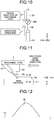
- FIG. 10 is a diagram illustrating a fourth comparative example where the direction in which the wire 30 is fed is opposite to the travel direction of the machining head 3.
- FIG. 10 is a diagram illustrating a fourth comparative example where the direction in which the wire 30 is fed is opposite to the travel direction of the machining head 3.
- FIG. 10 is a diagram illustrating the bead 50 as viewed in the Z direction, which is the emission direction of the laser beam.
- FIG. 11 is a diagram illustrating FIG. 10 as viewed in the Y direction, which is parallel to the surface of the base material 51.
- FIG. 12 is a diagram illustrating a cross-sectional shape of the bead 50 taken along line XII-XII in FIG. 11 as viewed in the directions of the arrows.
- the percentage of the amount of beam irradiation of the base material 51 that is blocked by the wire 30 immediately before the additive machining in a laser-beam irradiation region 300 is smaller than that in the case of FIG. 10 .
- the wire 30 is at a position that overlaps with the bead 50 as viewed in the direction in which the laser beam is emitted; thus, the area of the portion in which the base material 51 is covered by the wire 30 in the laser-beam irradiation region 300 is only the area of the bead 50.
- the area of a portion in which the base material 51 that is directly irradiated with the laser beam immediately before the additive machining in the laser-beam irradiation region 300 in FIG. 7 is larger than that in the case of FIG. 10 .
- preheating of the base material 51 is greater than that in the case of FIG. 10 and the temperature gradient is moderate during cooling; thus, as illustrated in FIG. 9 , the bead width of the bead 50 tends to be wider and the bead height thereof tends to be lower than those in FIG. 12 .
- the percentage of the amount of beam irradiation of the base material 51 that is blocked by the wire 30 immediately before the additive machining in the laser-beam irradiation region 300 is larger than that in the case of FIG. 7 .
- the area of the portion in which the base material 51 is covered by the wire 30 in the laser-beam irradiation region 300 corresponds to the area of the bead 50 and the area of the wire 30 as viewed in the direction in which the laser beam is emitted.
- the area of a portion of the base material 51 that is directly irradiated with the laser beam immediately before the additive machining in the laser-beam irradiation region 300 in FIG. 10 is smaller than that in the case of FIG. 7 .
- the preheating of the base material 51 is smaller than that in the case of FIG. 7 and the temperature gradient is steep during the cooling; thus, as illustrated in FIG. 12 , the bead width of the bead 50 tends to be narrower and the bead height thereof tends to be higher than those in FIG. 9 .
- the bead shapes are not off-center; however, the bead widths and bead heights are different.
- FIG. 13 is a diagram illustrating how the travel direction of the machining head 3 changes with respect to the direction in which the wire 30 is fed in the first embodiment.
- FIG. 13 includes the cases described in FIGS. 3 to 12 .
- FIG. 14 is an enlarged view of a portion surrounded by an alternate long and short dash line in FIG. 13 .
- the travel direction of the machining head 3 is indicated by a broken line.
- a portion of the laser-beam irradiation region 300 in FIG. 14 located to the lower right of the broken line is covered by the wire 30. Preheating of the base material 51 in the portion of the laser-beam irradiation region 300 located to the lower right of the broken line in FIG.
- the height of the bead 50 in the portion of the laser-beam irradiation region 300 located to the lower right of the broken line tends to be higher than that in the portion of the laser-beam irradiation region 300 located to the upper left of the broken line.
- the bead 50 in FIG. 6 is off-center such that it is higher on the left side than on the right side for the same reason.
- the bead width and bead height change as the amount of preheating of the base material 51 changes.
- the percentage of the amount of beam irradiation of the base material 51 that is blocked by the wire 30 immediately before the additive machining is smaller than that in the case of FIG. 10 .
- the laser output is not changed in the case of FIG. 7 , it is only necessary to increase the laser output in the case of FIG. 10 .
- the bead shape becomes off-center due to unevenness in the amount of preheating of the base material 51, which is dependent on the angle formed by the direction in which the wire 30 is fed and the travel direction of the machining head 3 within the plane perpendicular to the direction in which the laser beam is emitted.
- the gas pressure of the cooling gas ejected from the wire nozzle 31 or the beam profile of the laser beam may be adjusted depending on the angle described above.
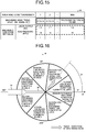
- FIG. 15 is a diagram illustrating an example of the machining condition table 25 according to the first embodiment.
- a machining condition number is assigned to each range of the travel direction ⁇ of the machining head 3 within the plane perpendicular to the direction in which the laser beam is emitted.
- the machining condition number serves as a machining condition index for specifying a machining condition, and the maximum machining condition number MAX can be determined as a parameter by a user.
- the travel direction ⁇ of the machining head 3 is an angle formed by the direction in which the wire 30 is fed and the travel direction of the machining head 3 within the plane perpendicular to the direction in which the laser beam is emitted.
- the ranges of the travel directions ⁇ of the machining head 3 corresponding to different machining condition numbers do not overlap with each other; thus, a machining-condition set value that corresponds to a given travel direction ⁇ of the machining head 3 is uniquely determined.
- the laser output value (kw) that is the output of a beam emitted by the beam source and the gas pressure (MPa) of the gas ejected from the gas nozzle 33 are stored as machining-condition set values in FIG. 15 .
- Machining-condition set values that depend on the travel direction ⁇ of the machining head 3 can be obtained by obtaining, in advance by experiment or the like, the correlation between the machining condition and an error between the shape into which the bead is actually formed and the target bead shape, with the correlation being dependent on the travel direction ⁇ of the machining head 3. Values obtained in this manner are stored as the machining-condition set values in FIG. 15 .
- the machining-condition selection unit 23 obtains the travel direction ⁇ of the machining head 3 on the basis of the movement-amount command value for each axial direction received from the axial-movement-amount generation unit 22, and selects a machining condition number from the machining condition table 25 using the obtained travel direction ⁇ of the machining head 3.
- the machining-condition selection unit 23 sends machining-condition set values that correspond to the selected machining condition number to the machining-condition output unit 24.
- the machining-condition output unit 24 outputs, to the laser head 32 and the gas nozzle 33, the machining-condition set values received from the machining-condition selection unit 23.
- the machining-condition selection unit 23 may only select a machining condition number from the machining condition table 25 using the obtained travel direction ⁇ of the machining head 3. In this case, the machining-condition selection unit 23 sends the selected machining condition number to the machining-condition output unit 24.
- the machining-condition output unit 24 references the machining condition table 25 on the basis of the machining condition number sent from the machining-condition selection unit 23 and outputs corresponding machining-condition set values to the laser head 32 and the gas nozzle 33.
- FIG. 16 is a diagram for describing how a machining condition is selected according to the first embodiment.
- the numerical control apparatus 2A may also adjust and select the beam profile of the laser beam in place of or in addition to the gas pressure of the gas ejected from the wire nozzle 31 in order to prevent off-centering of the bead shape. That is, a machining condition for the beam profile may be added as a machining condition for which a machining-condition set value is stored in the machining condition table 25.
- the beam profile of the laser beam is a machining condition that defines the intensity change within a beam irradiation region.
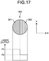
- FIG. 17 is a diagram for describing the beam profile of the laser beam according to the first embodiment.
- FIG. 17 illustrates the laser-beam irradiation region 300 as viewed in the Z direction, which is the direction in which the laser beam is emitted, when the coordinate system is set as illustrated in FIG. 2 .
- the irradiation region 300 of the base material 51 has a first region 301 and a second region 302.
- the percentage by which the laser beam emitted to the base material 51 is blocked is larger in the first region 301 in which the wire 30 is present as illustrated in FIG. 2 than that in the second region 302.
- the beam profile is adjusted such that, as illustrated in the lower portion of FIG. 17 , a laser output value P1 of the laser beam emitted by the laser head 32 to the first region 301 is larger than a laser output value P2 of the laser beam emitted by the laser head 32 to the second region 302.
- the beam profile may be added to the machining condition table 25 as a machining condition and the laser output value P1 and the laser output value P2 may be set for the first region 301 and the second region 302, respectively.
- the laser output value P1 that is a reference output may be set as the laser output value (kw), and the ratio of the laser output value to the reference output may be set for the first region 301 and the second region 302 in the machining condition table 25 as the beam profile.
- a numerical value 1 is set for the first region 301 and a numerical value (P2/P1) is set for the second region 302.
- the irradiation region 300 does not have to be divided into two as described above for setting the beam profile, as long as the heat distribution of the base material 51 within the irradiation region 300 can be adjusted.
- the heat distribution of the base material 51 within the irradiation region 300 may be adjusted by the combination of the gas pressure of the gas ejected from the wire nozzle 31 and the beam profile in order to prevent off-centering of the bead shape.
- a machining-condition set value for the beam profile is stored in the machining condition table 25, the numerical control apparatus 2A needs to be able to adjust the laser profile, but there is no limitation to the method for the adjustment.
- a machining-condition set value for the beam profile is given to the laser head 32 from the machining-condition output unit 24, and if the laser head 32 includes a deformable mirror that has changeable reflectance, a multi-laser that has a plurality of light sources, or the like, the laser profile can be adjusted.
- the additive manufacturing system 101 which includes the additive manufacturing apparatus 10A, can prevent off-centering of the bead shape with simple control and also keep the bead width and bead height constant by adjusting a set value for a machining condition for additive machining on the basis of the angle formed by the direction in which the wire 30 is fed and the travel direction of the machining head 3 within a plane perpendicular to the direction in which the laser beam is emitted.
- Conventional automatic welding robots employ a method of preventing off-centering of the bead shape and forming an ideal bead shape by rotating the machining head so that the angular difference between the feed direction of the wire and the travel direction of the machining head is constant all the time.
- the additive manufacturing system 101 according to the first embodiment which includes the additive manufacturing apparatus 10A, it is not necessary to rotate the machining head.
- problems that arise when the machining head is rotated such as twisting of the wire, vibrations of the end of the wire near the machining point, cutting of the wire, and interference between the wire and the device, can be avoided.
- FIG. 18 is a block diagram illustrating a functional configuration of an additive manufacturing system 102 according to a second embodiment of the present invention.
- the additive manufacturing system 102 includes a CAM apparatus 1B and an additive manufacturing apparatus 10B.
- the additive manufacturing apparatus 10B includes a numerical control apparatus 2B, the machining head 3, the servo amplifier 4, and a motor (not illustrated) that is driven by the servo amplifier 4.
- Differences in the additive manufacturing system 102 from the additive manufacturing system 101 according to the first embodiment are that the CAM apparatus 1B of the additive manufacturing system 102 includes a machining-condition selection unit 15 and the machining condition table 25 and that the numerical control apparatus 2B does not include a machining-condition selection unit.
- the CAD model 11, the machining condition table 25, the axial-movement-amount generation unit 22, the machining head 3, and the servo amplifier 4 are the same as those in the first embodiment. Differences in the additive manufacturing system 102 from the additive manufacturing system 101 will be described below.
- the machining-path generation unit 12 analyzes the CAD model 11 and thereby generates a machining path, and sends the generated machining path to the machining-program conversion unit 13 and the machining-condition selection unit 15.
- the machining-condition selection unit 15 obtains the movement-amount command value for each axial direction from the machining path received from the machining-path generation unit 12 and calculates the travel direction ⁇ of the machining head 3.
- the machining-condition selection unit 15 also references the machining condition table 25 and selects a machining condition number from the machining condition table 25 using the obtained travel direction ⁇ of the machining head 3, and sends the selected machining condition number to the machining-program conversion unit 13.
- the machining-program conversion unit 13 converts the machining path sent from the machining-path generation unit 12 and the machining condition number sent from the machining-condition selection unit 15 to the machining program 14.
- the machining condition number is specified by an M code. That is, the machining program 14 indicates a trajectory of the machining head 3 to thereby specify the machining path, and the machining program 14 includes machining-condition-number information, which is information on the selected machining condition.
- the machining-program analysis unit 21 of the numerical control apparatus 2B analyzes the machining program 14 and thereby determines the end-point coordinates of each machining path specified by the machining program 14, and sends the end-point coordinates of each machining path to the axial-movement-amount generation unit 22.
- the machining-program analysis unit 21 also acquires a machining condition number in each machining path by reading the M code in the machining program 14 and sends the machining condition number to a machining-condition output unit 26.
- the machining-condition output unit 26 references the machining condition table 25 of the numerical control apparatus 2B on the basis of the machining condition number sent from the machining-program analysis unit 21 and outputs corresponding machining-condition set values to the laser head 32 and the gas nozzle 33.
- the additive manufacturing system 102 can cause the CAM apparatus 1B to select a machining condition for additive machining on the basis of the angle formed by the direction in which the wire 30 is fed and the travel direction of the machining head 3 within a plane perpendicular to the direction in which the laser beam is emitted.
- the numerical control apparatuses 2A and 2B according to the first and second embodiments are each implemented by a computer system, such as a personal computer or a general-purpose computer.
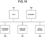
- FIG. 19 is a diagram illustrating a hardware configuration in a case in which the function of each of the numerical control apparatuses 2A and 2B according to the first and second embodiments is implemented by a computer system.
- the function of each of the numerical control apparatuses 2A and 2B is implemented by a computer system
- the function of each of the numerical control apparatuses 2A and 2B is implemented by a central processing unit (CPU) 201, a memory 202, a storage device 203, a display device 204, and an input device 205 as illustrated in FIG. 19 .
- CPU central processing unit
- the function of an additive manufacturing method that each of the numerical control apparatuses 2A and 2B performs is implemented by software, firmware, or a combination of software and firmware.
- the software or firmware is described in the form of a program and stored in the storage device 203.
- the CPU 201 implements the functions of the machining-program analysis unit 21, the axial-movement-amount generation unit 22, the machining-condition selection unit 23, and the machining-condition output units 24 and 26 by loading the software or firmware, which is stored in the storage device 203, into the memory 202 and executing it.
- the computer system includes the storage device 203 for storing programs that, upon execution, by the CPU 201, of the functions of the machining-program analysis unit 21, the axial-movement-amount generation unit 22, the machining-condition selection unit 23, and the machining-condition output units 24 and 26, cause steps for performing the additive manufacturing method according to the first and second embodiments to be executed. It can also be said that these programs cause a computer to execute processing that is implemented by the functions of the machining-program analysis unit 21, the axial-movement-amount generation unit 22, the machining-condition selection unit 23, and the machining-condition output units 24 and 26.
- the memory 202 can be a volatile storage area, such as a random access memory (RAM).
- the storage device 203 which stores the machining program 14 and the machining condition table 25, can be a nonvolatile or volatile semiconductor memory, such as a read only memory (ROM) and a flash memory, or a magnetic disk.
- ROM read only memory
- Specific examples of the display device 204 are a monitor and a display.
- Specific examples of the input device 205 are a keyboard, a mouse, and a touch panel.
- 1A, 1B CAM apparatus 2A, 2B numerical control apparatus; 3 machining head; 4 servo amplifier; 10A, 10B additive manufacturing apparatus; 11 CAD model; 12 machining-path generation unit; 13 machining-program conversion unit; 14 machining program; 15 machining-condition selection unit; 21 machining-program analysis unit; 22 axial-movement-amount generation unit; 23 machining-condition selection unit; 24, 26 machining-condition output unit; 25 machining condition table; 30 wire; 31 wire nozzle; 32 laser head; 33 gas nozzle; 50 bead; 51 base material; 101, 102 additive manufacturing system; 201 CPU; 202 memory; 203 storage device; 204 display device; 205 input device; 300 irradiation region; 301 first region; 302 second region.
Landscapes
- Engineering & Computer Science (AREA)
- Physics & Mathematics (AREA)
- Optics & Photonics (AREA)
- Mechanical Engineering (AREA)
- Plasma & Fusion (AREA)
- Laser Beam Processing (AREA)
- Welding Or Cutting Using Electron Beams (AREA)
Abstract
Description
- The present invention relates to an additive manufacturing apparatus, an additive manufacturing system, and an additive manufacturing method for performing wire-type additive manufacturing machining.
- It is known that, when wire-type additive manufacturing machining is performed under preset machining conditions, a shape error with respect to an ideal bead shape occurs depending on the angular difference between the feed direction of the wire and the travel direction of the machining head. The machining conditions include beam output, gas pressure, and the like, and the ideal bead shape refers to a bead shape having a symmetrical cross-sectional shape and a constant ratio of the bead width to the bead height. Occurrence of a shape error of the bead shape can mean that the bead shape is off-center such that its cross-sectional shape becomes asymmetrical or that the ratio of the bead width to the bead height deviates from a constant value.
- The relationship between the machining travel direction and off-centering of the bead shape is described in
Patent Literature 1.Patent Literature 1 describes that, when arc welding is performed by moving a welding torch that is tilted toward one of the directions that are orthogonal to the welding travel direction, an off-centered bead is generated due to unevenness in heat input to the base material. - Patent Literature 1: Japanese Patent Application Laid-open No.
2013-146753 - There is a method for causing the angular difference between the feed direction of the wire and the travel direction of the machining head to be constant all the time and thereby creating an ideal bead shape. In this method, the workpiece itself is rotated. Use of this method, however, causes a problem in that the machining region is reduced due to the need to attach a rotation table to the machining device, a problem in that there is increased complexity because the number of axes of the device is increased, and other problems. There has thus been a desire to avoid off-centering of the bead shape in the wire-type additive manufacturing machining by using simple control.
- The present invention has been achieved in view of the above, and an object of the present invention is to provide an additive manufacturing apparatus that can prevent off-centering of the bead shape by using simple control.
- To solve the problems described above and achieve the object described above, an additive manufacturing apparatus according to an aspect of the present invention performs additive machining by controlling a machining head that includes a wire nozzle to feed a wire-like material to a machining region on a surface of a base material, a beam source capable of emitting a beam to the wire-like material, and a gas nozzle placed such that the beam source is interposed between the gas nozzle and the wire nozzle, the gas nozzle directing a gas toward the machining region. The additive manufacturing apparatus according to an aspect of the present invention includes a machining-condition selection unit to obtain an angle that is formed between a direction in which the wire-like material is fed and a travel direction of the machining head, when viewed in a direction in which the beam is emitted, and to select a machining condition for the additive machining on a basis of the angle.
- An additive manufacturing apparatus according to the present invention produces an effect of enabling prevention of off-centering of the bead shape by using simple control.
-
-
FIG. 1 is a block diagram illustrating a functional configuration of an additive manufacturing system according to a first embodiment of the present invention. -
FIG. 2 is a diagram illustrating a configuration of a machining head according to the first embodiment. -
FIG. 3 is a diagram illustrating a first comparative example where the direction in which a wire is fed is opposite to the travel direction of the machining head. -
FIG. 4 is a diagram illustrating a cross-sectional shape of a bead taken along line IV-IV inFIG. 3 as viewed in the directions of the arrows. -
FIG. 5 is a diagram illustrating a second comparative example where the direction in which the wire is fed and the travel direction of the machining head form a right angle. -
FIG. 6 is a diagram illustrating a cross-sectional shape of the bead taken along line VI-VI inFIG. 5 as viewed in the directions of the arrows. -
FIG. 7 is a diagram illustrating a third comparative example where the direction in which the wire is fed is the same as the travel direction of the machining head. -
FIG. 8 is a diagram illustratingFIG. 7 as viewed in a Y direction, which is parallel to the surface of a base material. -
FIG. 9 is a diagram illustrating a cross-sectional shape of the bead taken along line IX-IX inFIG. 8 as viewed in the directions of the arrows. -
FIG. 10 is a diagram illustrating a fourth comparative example where the direction in which the wire is fed is opposite to the travel direction of the machining head. -
FIG. 11 is a diagram illustratingFIG. 10 as viewed in the Y direction, which is parallel to the surface of the base material. -
FIG. 12 is a diagram illustrating a cross-sectional shape of the bead taken along line XII-XII inFIG. 11 as viewed in the directions of the arrows. -
FIG. 13 is a diagram illustrating how the travel direction of the machining head changes with respect to the direction in which the wire is fed in the first embodiment. -
FIG. 14 is an enlarged view of a portion surrounded by an alternate long and short dash line inFIG. 13 . -
FIG. 15 is a diagram illustrating an example of a machining condition table according to the first embodiment. -
FIG. 16 is a diagram for describing how a machining condition is selected according to the first embodiment. -
FIG. 17 is a diagram for describing the beam profile of a laser beam according to the first embodiment. -
FIG. 18 is a block diagram illustrating a functional configuration of an additive manufacturing system according to a second embodiment of the present invention. -
FIG. 19 is a diagram illustrating a hardware configuration in a case in which a function of each of the numerical control apparatuses according to the first and second embodiments is implemented by a computer system. - An additive manufacturing apparatus, an additive manufacturing system, and an additive manufacturing method according to embodiments of the present invention are described below in detail with reference to the drawings. The present invention is not limited to the embodiments.
-
FIG. 1 is a block diagram illustrating a functional configuration of anadditive manufacturing system 101 according to a first embodiment of the present invention. Theadditive manufacturing system 101 includes a computer aided manufacturing (CAM)apparatus 1A and anadditive manufacturing apparatus 10A. Theadditive manufacturing apparatus 10A includes anumerical control apparatus 2A, amachining head 3, aservo amplifier 4, and a motor (not illustrated) that is driven by theservo amplifier 4. -
FIG. 2 is a diagram illustrating a configuration of themachining head 3 according to the first embodiment. Themachining head 3 includes awire nozzle 31 that feeds awire 30 that is a wire-like material; alaser head 32 that is a beam source that can emit a laser beam to the end of thewire 30; and agas nozzle 33 that directs gas toward a machining region on the surface of abase material 51. Thewire nozzle 31 feeds thewire 30 onto thebase material 51 in a certain direction and at a constant speed. Thewire 30 fed by thewire nozzle 31 is heated and melted by the laser beam in the machining region to form abead 50. That is, the machining region is a region on the surface of thebase material 51 in which thebead 50 is formed. Thegas nozzle 33 is placed such that thelaser head 32 is interposed between thegas nozzle 33 and thewire nozzle 31, and an electro-pneumatic valve controls the ejection of the gas that is used for cooling thebead 50 formed in the machining region. During additive machining, themachining head 3 moves in the travel direction that is the direction perpendicular to the Z direction inFIG. 2 while the laser beam is emitted onto the end of thewire 30, with the Z direction being the emission direction of the laser beam. Consequently, thebead 50 is formed such that it extends in a direction opposite to the travel direction on the surface of thebase material 51. In this case, because the laser beam emitted onto the surface of thebase material 51 is blocked by thewire 30 itself, the condition of the heat input to thebase material 51 varies as described below in accordance with the relationship between the covered region and the travel direction of themachining head 3. The direction in which thewire nozzle 31 feeds thewire 30 is opposite to the direction in which thegas nozzle 33 emits the gas when viewed in the direction in which thelaser head 32 emits the laser beam. InFIG. 2 , the direction in which thelaser head 32 emits the laser beam is in the Z direction and the directions parallel to the surface of thebase material 51 are in the X direction and the Y direction, which are perpendicular to the Z direction. The direction in which thewire nozzle 31 feeds thewire 30 is in the X direction when the direction is projected perpendicularly on the XY plane. Because thelaser head 32, which includes a laser oscillator, is used as a beam source, the beam used here is a laser beam; however, the beam source may be changed to an electron beam source and the beam may be an electron beam. That is, there is no limitation to the beam source as long as a beam that can heat and melt thewire 30 is available. - The
CAM apparatus 1A includes a computer-aided design (CAD)model 11 that specifies the target shape to be additively manufactured; a machining-path generation unit 12 that analyzes theCAD model 11 and thereby generates a machining path; and a machining-program conversion unit 13 that converts the machining path generated by the machining-path generation unit 12 to amachining program 14. The machining-program conversion unit 13 sends the generatedmachining program 14 to thenumerical control apparatus 2A. Themachining program 14 indicates a trajectory of themachining head 3 to thereby specify the machining path. - The
numerical control apparatus 2A includes a machining-program analysis unit 21, an axial-movement-amount generation unit 22, a machining-condition selection unit 23, a machining-condition output unit 24, and a machining condition table 25. - The machining-program analysis unit 21 analyzes the
machining program 14 and thereby determines the end-point coordinates of each machining path specified by themachining program 14, and sends the end-point coordinates of each machining path to the axial-movement-amount generation unit 22. - The axial-movement-
amount generation unit 22 receives the result of analysis performed by the machining-program analysis unit 21. The axial-movement-amount generation unit 22 generates a movement-amount command value for each axial direction per control cycle of thenumerical control apparatus 2A on the basis of the end-point coordinates of each machining path. Each axis here corresponds to a drive shaft that is driven by a driving device (not illustrated) that can change the relative positions of themachining head 3 and thebase material 51. The axial-movement-amount generation unit 22 sends the generated movement-amount command value for each axial direction to theservo amplifier 4 and the machining-condition selection unit 23. - The machining condition table 25 is a data table for presetting set values of machining conditions according to the travel direction of the
machining head 3. - The machining-
condition selection unit 23 calculates a travel direction θ of themachining head 3 on the basis of the movement-amount command value for each axial direction received from the axial-movement-amount generation unit 22. The travel direction of themachining head 3 is in a direction perpendicular to the Z direction, which is the emission direction of the laser beam as described above. The travel direction θ of themachining head 3 can thus form an angle of 360° within the XY plane around an axis of the emission direction of the laser beam. Here, the travel direction θ is an angle formed between the travel direction of themachining head 3 and a reference direction when viewed in the emission direction of the laser beam. When the reference direction is in the positive X direction and the travel direction of themachining head 3 is in the positive X direction, 8=0 degrees. The direction indicated by an arrow X inFIG. 2 is defined as the positive X direction, and the positive X direction may be simply referred to as the X direction hereinafter. Thus, the travel direction θ is obtained when θ=tan-1 (movement-amount command value in the Y direction/movement-amount command value in the X direction). InFIG. 2 , the direction in which thewire 30 is fed by thewire nozzle 31 is in the positive X direction, which is the reference direction, when the direction is projected perpendicularly on the XY plane. Thus, the travel direction θ of themachining head 3 is an angle formed between the direction in which thewire 30 is fed and the travel direction of themachining head 3 when viewed in the direction in which the laser beam is emitted. - The machining-
condition selection unit 23 references the machining condition table 25 and selects a machining condition from the machining condition table 25 using the travel direction θ of themachining head 3, which is obtained in the manner described above. The machining-condition selection unit 23 then sends a machining-condition set value that is a set value for the selected machining condition to the machining-condition output unit 24. - The machining-
condition output unit 24 outputs the machining-condition set value received from the machining-condition selection unit 23 to thelaser head 32 and thegas nozzle 33. - The
laser head 32 receives, from the machining-condition output unit 24, a laser output value (kw) as the machining-condition set value and controls the laser oscillator such that the received laser output value is obtained. - The
gas nozzle 33 receives, from the machining-condition output unit 24, a gas pressure (MPa) as the machining-condition set value and controls the electro-pneumatic valve such that the received gas pressure is obtained. - On the basis of the movement-amount command value for each axial direction received from the axial-movement-
amount generation unit 22, theservo amplifier 4 drives the motor that moves, in each axial direction, a table (not illustrated) on which thebase material 51, which is the workpiece, is placed. - The
additive manufacturing apparatus 10A according to the first embodiment performs additive machining on the basis of the machining condition table 25, which stores machining conditions in accordance with the travel direction of themachining head 3 as described above; however, a description will be given, using comparative examples, of a case in which additive machining is performed under the same machining condition all the time with no consideration given to the travel direction of themachining head 3. -
FIG. 3 is a diagram illustrating a first comparative example where the direction in which thewire 30 is fed is opposite to the travel direction of themachining head 3.FIG. 4 is a diagram illustrating a cross-sectional shape of thebead 50 taken along line IV-IV inFIG. 3 as viewed in the directions of the arrows.FIG. 5 is a diagram illustrating a second comparative example where the direction in which thewire 30 is fed and the travel direction of themachining head 3 form a right angle.FIG. 6 is a diagram illustrating a cross-sectional shape of thebead 50 taken along line VI-VI inFIG. 5 as viewed in the directions of the arrows.FIGS. 3 and5 are diagrams illustrating thebead 50 as viewed in the emission direction of the laser beam. - As illustrated in
FIG. 3 , which is a view in the emission direction of the laser beam, which is a direction perpendicular to the drawing plane ofFIG. 3 , when the direction in which thewire 30 is fed is opposite to the travel direction of themachining head 3, the cross-sectional shape of thebead 50 is bilaterally symmetric as illustrated inFIG. 4 . This is because the percentage of the laser beam, emitted by thelaser head 32, that is blocked by thewire 30 does not become uneven on the right and left sides of thewire 30 on the drawing plane ofFIG. 3 . As a result, there is no unevenness in heating of thebase material 51 by the laser beam on the right and left sides of thebase material 51 inFIG. 4 ; thus, the cross-sectional shape of thebead 50 becomes bilaterally symmetric. As will be described in detail below, in a case where the direction in which thewire 30 is fed is the same as the travel direction of themachining head 3 when viewed in the emission direction of the laser beam, which is the direction perpendicular to the drawing plane ofFIG. 3 , the cross-sectional shape of thebead 50 changes but remains bilaterally symmetric. - In contrast, when the direction in which the
wire 30 is fed and the travel direction of themachining head 3 form a right angle as illustrated inFIG. 5 , the cross-sectional shape of thebead 50 is asymmetrical and off-center as illustrated inFIG. 6 . The bead shape that is symmetrical and is not off-center illustrated inFIG. 3 is indicated by a broken line inFIG. 6 . The cross-sectional shape of thebead 50 becomes off-centered because the laser beam emitted by thelaser head 32 to thebase material 51 is blocked by thewire 30 by different percentages on the upper and lower sides of the end of thewire 30 on the drawing plane ofFIG. 5 . That is, inFIG. 5 , the percentage by which the laser beam emitted by thelaser head 32 to thebase material 51 is blocked by thewire 30 is larger on the lower side of the end of thewire 30 than that on the upper side thereof. As a result, when themachining head 3 travels to the right on the drawing plane ofFIG. 5 , a portion of thebase material 51 that is located on the upper side of the end of thewire 30 is heated more than a portion of thebase material 51 that is located on the lower side thereof. Consequently, on the drawing plane ofFIG. 6 , thebead 50 has a lower height in a portion on the right side of thebase material 51 than on the left side of thebase material 51, the right side being heated more than on the left side on which the percentage of the laser beam blocked by thewire 30 is higher, which produces an off-center in the cross-sectional shape of thebead 50. - As described above, in a wire-type welding technology using a beam source as a heat source, the percentage of the amount of beam irradiation of the
base material 51 that is blocked by thewire 30 immediately before the additive machining varies depending on the angular difference between the wire feed direction and the travel direction of themachining head 3, which is the welding travel direction. The width and height of thebead 50 formed by the additive machining change depending on the variation of the percentage of the amount of beam irradiation blocked by thewire 30. This is described in greater detail using comparative examples below. -
FIG. 7 is a diagram illustrating a third comparative example where the direction in which thewire 30 is fed is the same as the travel direction of themachining head 3.FIG. 7 is a diagram illustrating thebead 50 as viewed in the Z direction, which is the emission direction of the laser beam.FIG. 8 is a diagram illustratingFIG. 7 as viewed in the Y direction, which is parallel to the surface of thebase material 51.FIG. 9 is a diagram illustrating a cross-sectional shape of thebead 50 taken along line IX-IX inFIG. 8 as viewed in the directions of the arrows.FIG. 10 is a diagram illustrating a fourth comparative example where the direction in which thewire 30 is fed is opposite to the travel direction of themachining head 3.FIG. 10 is a diagram illustrating thebead 50 as viewed in the Z direction, which is the emission direction of the laser beam.FIG. 11 is a diagram illustratingFIG. 10 as viewed in the Y direction, which is parallel to the surface of thebase material 51.FIG. 12 is a diagram illustrating a cross-sectional shape of thebead 50 taken along line XII-XII inFIG. 11 as viewed in the directions of the arrows. - When the direction in which the
wire 30 is fed is the same as the travel direction of themachining head 3 as illustrated inFIG. 7 , the percentage of the amount of beam irradiation of thebase material 51 that is blocked by thewire 30 immediately before the additive machining in a laser-beam irradiation region 300 is smaller than that in the case ofFIG. 10 . In the case ofFIG. 7 , thewire 30 is at a position that overlaps with thebead 50 as viewed in the direction in which the laser beam is emitted; thus, the area of the portion in which thebase material 51 is covered by thewire 30 in the laser-beam irradiation region 300 is only the area of thebead 50. The area of a portion in which thebase material 51 that is directly irradiated with the laser beam immediately before the additive machining in the laser-beam irradiation region 300 inFIG. 7 is larger than that in the case ofFIG. 10 . As a result, inFIG. 7 , preheating of thebase material 51 is greater than that in the case ofFIG. 10 and the temperature gradient is moderate during cooling; thus, as illustrated inFIG. 9 , the bead width of thebead 50 tends to be wider and the bead height thereof tends to be lower than those inFIG. 12 . - When the direction in which the
wire 30 is fed is opposite to the travel direction of themachining head 3 as illustrated inFIG. 10 , the percentage of the amount of beam irradiation of thebase material 51 that is blocked by thewire 30 immediately before the additive machining in the laser-beam irradiation region 300 is larger than that in the case ofFIG. 7 . In the case ofFIG. 10 , the area of the portion in which thebase material 51 is covered by thewire 30 in the laser-beam irradiation region 300 corresponds to the area of thebead 50 and the area of thewire 30 as viewed in the direction in which the laser beam is emitted. The area of a portion of thebase material 51 that is directly irradiated with the laser beam immediately before the additive machining in the laser-beam irradiation region 300 inFIG. 10 is smaller than that in the case ofFIG. 7 . As a result, inFIG. 10 , the preheating of thebase material 51 is smaller than that in the case ofFIG. 7 and the temperature gradient is steep during the cooling; thus, as illustrated inFIG. 12 , the bead width of thebead 50 tends to be narrower and the bead height thereof tends to be higher than those inFIG. 9 . As described above, in the cases ofFIGS. 7 and10 , the bead shapes are not off-center; however, the bead widths and bead heights are different. -
FIG. 13 is a diagram illustrating how the travel direction of themachining head 3 changes with respect to the direction in which thewire 30 is fed in the first embodiment.FIG. 13 includes the cases described inFIGS. 3 to 12 .FIG. 14 is an enlarged view of a portion surrounded by an alternate long and short dash line inFIG. 13 . InFIG. 14 , the travel direction of themachining head 3 is indicated by a broken line. A portion of the laser-beam irradiation region 300 inFIG. 14 located to the lower right of the broken line is covered by thewire 30. Preheating of thebase material 51 in the portion of the laser-beam irradiation region 300 located to the lower right of the broken line inFIG. 14 is thus lower than that in the portion of the laser-beam irradiation region 300 located to the upper left of the broken line, and the height of thebead 50 in the portion of the laser-beam irradiation region 300 located to the lower right of the broken line tends to be higher than that in the portion of the laser-beam irradiation region 300 located to the upper left of the broken line. Thebead 50 inFIG. 6 is off-center such that it is higher on the left side than on the right side for the same reason. - As described above, the bead width and bead height change as the amount of preheating of the
base material 51 changes. Thus, to keep the bead width and bead height constant, it is only necessary to change the laser output depending on the angle formed by the direction in which thewire 30 is fed and the travel direction of themachining head 3 within a plane perpendicular to the direction in which the laser beam is emitted. Specifically, in the case ofFIG. 7 , the percentage of the amount of beam irradiation of thebase material 51 that is blocked by thewire 30 immediately before the additive machining is smaller than that in the case ofFIG. 10 . Thus, in the case ofFIG. 7 , it is only necessary to reduce the laser output. When the laser output is not changed in the case ofFIG. 7 , it is only necessary to increase the laser output in the case ofFIG. 10 . - Additionally, the bead shape becomes off-center due to unevenness in the amount of preheating of the
base material 51, which is dependent on the angle formed by the direction in which thewire 30 is fed and the travel direction of themachining head 3 within the plane perpendicular to the direction in which the laser beam is emitted. Thus, to prevent off-centering of the bead shape, it is only necessary to correct unevenness in the amount of heat input within the laser-beam irradiation region 300. Specifically, the gas pressure of the cooling gas ejected from thewire nozzle 31 or the beam profile of the laser beam may be adjusted depending on the angle described above. -
FIG. 15 is a diagram illustrating an example of the machining condition table 25 according to the first embodiment. In the machining condition table 25 inFIG. 15 , a machining condition number is assigned to each range of the travel direction θ of themachining head 3 within the plane perpendicular to the direction in which the laser beam is emitted. The machining condition number serves as a machining condition index for specifying a machining condition, and the maximum machining condition number MAX can be determined as a parameter by a user. As described above, since the direction in which thewire 30 is fed by thewire nozzle 31 is defined as the positive X direction within the plane perpendicular to the direction in which the laser beam is emitted, the travel direction θ of themachining head 3 is an angle formed by the direction in which thewire 30 is fed and the travel direction of themachining head 3 within the plane perpendicular to the direction in which the laser beam is emitted. The ranges of the travel directions θ of themachining head 3 corresponding to different machining condition numbers do not overlap with each other; thus, a machining-condition set value that corresponds to a given travel direction θ of themachining head 3 is uniquely determined. The laser output value (kw) that is the output of a beam emitted by the beam source and the gas pressure (MPa) of the gas ejected from thegas nozzle 33 are stored as machining-condition set values inFIG. 15 . Machining-condition set values that depend on the travel direction θ of themachining head 3 can be obtained by obtaining, in advance by experiment or the like, the correlation between the machining condition and an error between the shape into which the bead is actually formed and the target bead shape, with the correlation being dependent on the travel direction θ of themachining head 3. Values obtained in this manner are stored as the machining-condition set values inFIG. 15 . There is no limitation to the machining condition for which machining-condition set values are stored in the machining condition table 25 as long as it is correlated with the error of the bead shape and can be controlled from thenumerical control apparatus 2A. - The machining-
condition selection unit 23 obtains the travel direction θ of themachining head 3 on the basis of the movement-amount command value for each axial direction received from the axial-movement-amount generation unit 22, and selects a machining condition number from the machining condition table 25 using the obtained travel direction θ of themachining head 3. The machining-condition selection unit 23 sends machining-condition set values that correspond to the selected machining condition number to the machining-condition output unit 24. The machining-condition output unit 24 outputs, to thelaser head 32 and thegas nozzle 33, the machining-condition set values received from the machining-condition selection unit 23. - If the machining-
condition output unit 24 can reference the machining condition table 25, the machining-condition selection unit 23 may only select a machining condition number from the machining condition table 25 using the obtained travel direction θ of themachining head 3. In this case, the machining-condition selection unit 23 sends the selected machining condition number to the machining-condition output unit 24. The machining-condition output unit 24 references the machining condition table 25 on the basis of the machining condition number sent from the machining-condition selection unit 23 and outputs corresponding machining-condition set values to thelaser head 32 and thegas nozzle 33. -
FIG. 16 is a diagram for describing how a machining condition is selected according to the first embodiment.FIG. 16 is a diagram illustrating an example that describes which machining condition number is selected in accordance with the travel direction θ of themachining head 3 within the XY plane when the maximum machining condition number MAX=8 in the machining condition table 25 inFIG. 15 . If themachining head 3 travels as illustrated inFIG. 16 , amachining condition number 2 is selected by the machining-condition selection unit 23. - As described above, the
numerical control apparatus 2A may also adjust and select the beam profile of the laser beam in place of or in addition to the gas pressure of the gas ejected from thewire nozzle 31 in order to prevent off-centering of the bead shape. That is, a machining condition for the beam profile may be added as a machining condition for which a machining-condition set value is stored in the machining condition table 25. The beam profile of the laser beam is a machining condition that defines the intensity change within a beam irradiation region. -
FIG. 17 is a diagram for describing the beam profile of the laser beam according to the first embodiment.FIG. 17 illustrates the laser-beam irradiation region 300 as viewed in the Z direction, which is the direction in which the laser beam is emitted, when the coordinate system is set as illustrated inFIG. 2 . Theirradiation region 300 of thebase material 51 has afirst region 301 and asecond region 302. When the travel direction of themachining head 3 is in the Y direction, the percentage by which the laser beam emitted to thebase material 51 is blocked is larger in thefirst region 301 in which thewire 30 is present as illustrated inFIG. 2 than that in thesecond region 302. - In such a case, the beam profile is adjusted such that, as illustrated in the lower portion of
FIG. 17 , a laser output value P1 of the laser beam emitted by thelaser head 32 to thefirst region 301 is larger than a laser output value P2 of the laser beam emitted by thelaser head 32 to thesecond region 302. The beam profile may be added to the machining condition table 25 as a machining condition and the laser output value P1 and the laser output value P2 may be set for thefirst region 301 and thesecond region 302, respectively. Alternatively, the laser output value P1 that is a reference output may be set as the laser output value (kw), and the ratio of the laser output value to the reference output may be set for thefirst region 301 and thesecond region 302 in the machining condition table 25 as the beam profile. In this case, as the ratio of the laser output value to the reference output, anumerical value 1 is set for thefirst region 301 and a numerical value (P2/P1) is set for thesecond region 302. Theirradiation region 300 does not have to be divided into two as described above for setting the beam profile, as long as the heat distribution of thebase material 51 within theirradiation region 300 can be adjusted. Thus, it is possible to define a function for determining the laser output value within a two-dimensional plane such that the laser output of the laser beam emitted to theirradiation region 300 changes continuously. Additionally, the heat distribution of thebase material 51 within theirradiation region 300 may be adjusted by the combination of the gas pressure of the gas ejected from thewire nozzle 31 and the beam profile in order to prevent off-centering of the bead shape. - If a machining-condition set value for the beam profile is stored in the machining condition table 25, the
numerical control apparatus 2A needs to be able to adjust the laser profile, but there is no limitation to the method for the adjustment. In this case, a machining-condition set value for the beam profile is given to thelaser head 32 from the machining-condition output unit 24, and if thelaser head 32 includes a deformable mirror that has changeable reflectance, a multi-laser that has a plurality of light sources, or the like, the laser profile can be adjusted. - As described above, the
additive manufacturing system 101 according to the first embodiment, which includes theadditive manufacturing apparatus 10A, can prevent off-centering of the bead shape with simple control and also keep the bead width and bead height constant by adjusting a set value for a machining condition for additive machining on the basis of the angle formed by the direction in which thewire 30 is fed and the travel direction of themachining head 3 within a plane perpendicular to the direction in which the laser beam is emitted. - Conventional automatic welding robots employ a method of preventing off-centering of the bead shape and forming an ideal bead shape by rotating the machining head so that the angular difference between the feed direction of the wire and the travel direction of the machining head is constant all the time. In contrast, with the
additive manufacturing system 101 according to the first embodiment, which includes theadditive manufacturing apparatus 10A, it is not necessary to rotate the machining head. Thus, problems that arise when the machining head is rotated, such as twisting of the wire, vibrations of the end of the wire near the machining point, cutting of the wire, and interference between the wire and the device, can be avoided. -
FIG. 18 is a block diagram illustrating a functional configuration of anadditive manufacturing system 102 according to a second embodiment of the present invention. Theadditive manufacturing system 102 includes aCAM apparatus 1B and anadditive manufacturing apparatus 10B. Theadditive manufacturing apparatus 10B includes anumerical control apparatus 2B, themachining head 3, theservo amplifier 4, and a motor (not illustrated) that is driven by theservo amplifier 4. - Differences in the
additive manufacturing system 102 from theadditive manufacturing system 101 according to the first embodiment are that theCAM apparatus 1B of theadditive manufacturing system 102 includes a machining-condition selection unit 15 and the machining condition table 25 and that thenumerical control apparatus 2B does not include a machining-condition selection unit. TheCAD model 11, the machining condition table 25, the axial-movement-amount generation unit 22, themachining head 3, and theservo amplifier 4 are the same as those in the first embodiment. Differences in theadditive manufacturing system 102 from theadditive manufacturing system 101 will be described below. - The machining-
path generation unit 12 analyzes theCAD model 11 and thereby generates a machining path, and sends the generated machining path to the machining-program conversion unit 13 and the machining-condition selection unit 15. - The machining-
condition selection unit 15 obtains the movement-amount command value for each axial direction from the machining path received from the machining-path generation unit 12 and calculates the travel direction θ of themachining head 3. The machining-condition selection unit 15 also references the machining condition table 25 and selects a machining condition number from the machining condition table 25 using the obtained travel direction θ of themachining head 3, and sends the selected machining condition number to the machining-program conversion unit 13. - The machining-
program conversion unit 13 converts the machining path sent from the machining-path generation unit 12 and the machining condition number sent from the machining-condition selection unit 15 to themachining program 14. In themachining program 14 generated by the machining-program conversion unit 13, the machining condition number is specified by an M code. That is, themachining program 14 indicates a trajectory of themachining head 3 to thereby specify the machining path, and themachining program 14 includes machining-condition-number information, which is information on the selected machining condition. - The machining-program analysis unit 21 of the
numerical control apparatus 2B analyzes themachining program 14 and thereby determines the end-point coordinates of each machining path specified by themachining program 14, and sends the end-point coordinates of each machining path to the axial-movement-amount generation unit 22. The machining-program analysis unit 21 also acquires a machining condition number in each machining path by reading the M code in themachining program 14 and sends the machining condition number to a machining-condition output unit 26. - The machining-
condition output unit 26 references the machining condition table 25 of thenumerical control apparatus 2B on the basis of the machining condition number sent from the machining-program analysis unit 21 and outputs corresponding machining-condition set values to thelaser head 32 and thegas nozzle 33. - As described above, the
additive manufacturing system 102 according to the second embodiment can cause theCAM apparatus 1B to select a machining condition for additive machining on the basis of the angle formed by the direction in which thewire 30 is fed and the travel direction of themachining head 3 within a plane perpendicular to the direction in which the laser beam is emitted. - The
numerical control apparatuses FIG. 19 is a diagram illustrating a hardware configuration in a case in which the function of each of thenumerical control apparatuses numerical control apparatuses numerical control apparatuses memory 202, astorage device 203, adisplay device 204, and aninput device 205 as illustrated inFIG. 19 . The function of an additive manufacturing method that each of thenumerical control apparatuses storage device 203. TheCPU 201 implements the functions of the machining-program analysis unit 21, the axial-movement-amount generation unit 22, the machining-condition selection unit 23, and the machining-condition output units storage device 203, into thememory 202 and executing it. That is, the computer system includes thestorage device 203 for storing programs that, upon execution, by theCPU 201, of the functions of the machining-program analysis unit 21, the axial-movement-amount generation unit 22, the machining-condition selection unit 23, and the machining-condition output units amount generation unit 22, the machining-condition selection unit 23, and the machining-condition output units memory 202 can be a volatile storage area, such as a random access memory (RAM). Thestorage device 203, which stores themachining program 14 and the machining condition table 25, can be a nonvolatile or volatile semiconductor memory, such as a read only memory (ROM) and a flash memory, or a magnetic disk. Specific examples of thedisplay device 204 are a monitor and a display. Specific examples of theinput device 205 are a keyboard, a mouse, and a touch panel. - The configurations in the embodiments described above represent some examples of an aspect of the present invention, and they can be combined with another publicly known technique and partially omitted or modified without departing from the spirit of the present invention.
- 1A, 1B CAM apparatus; 2A, 2B numerical control apparatus; 3 machining head; 4 servo amplifier; 10A, 10B additive manufacturing apparatus; 11 CAD model; 12 machining-path generation unit; 13 machining-program conversion unit; 14 machining program; 15 machining-condition selection unit; 21 machining-program analysis unit; 22 axial-movement-amount generation unit; 23 machining-condition selection unit; 24, 26 machining-condition output unit; 25 machining condition table; 30 wire; 31 wire nozzle; 32 laser head; 33 gas nozzle; 50 bead; 51 base material; 101, 102 additive manufacturing system; 201 CPU; 202 memory; 203 storage device; 204 display device; 205 input device; 300 irradiation region; 301 first region; 302 second region.
Claims (8)
- An additive manufacturing apparatus that performs additive machining by controlling a machining head that includes a wire nozzle to feed a wire-like material to a machining region on a surface of a base material, a beam source capable of emitting a beam to an end of the wire-like material, and a gas nozzle placed such that the beam source is interposed between the gas nozzle and the wire nozzle, the gas nozzle directing a gas toward the machining region, the apparatus comprising
a machining-condition selection unit to obtain an angle that is formed between a direction in which the wire-like material is fed and a travel direction of the machining head, when viewed in a direction in which the beam is emitted, and to select a machining condition for the additive machining on a basis of the angle. - The additive manufacturing apparatus according to claim 1, further comprising a machining condition table that stores the machining condition that is dependent on the angle, wherein
the machining-condition selection unit obtains the angle on a basis of a machining program that specifies a machining path and selects the machining condition using the angle and the machining condition table. - The additive manufacturing apparatus according to claim 2, wherein the machining condition table stores an output value of the beam and a gas pressure of the gas as the machining condition that is dependent on the angle.
- The additive manufacturing apparatus according to claim 3, wherein the machining condition table stores a beam profile that specifies intensity change within an irradiation region of the beam as the machining condition that is dependent on the angle.
- An additive manufacturing system that performs additive machining by controlling a machining head that includes a wire nozzle to feed a wire-like material to a machining region on a surface of a base material, a beam source capable of emitting a beam to an end of the wire-like material, and a gas nozzle placed such that the beam source is interposed between the gas nozzle and the wire nozzle, the gas nozzle directing a gas toward the machining region, the additive manufacturing system comprising:a machining condition table that stores a machining condition that is used for the additive machining and is dependent on an angle that is formed between a direction in which the wire-like material is fed and a travel direction of the machining head, when viewed in a direction in which the beam is emitted;a machining-condition selection unit to obtain the angle on a basis of a machining path and to select the machining condition using the angle and the machining condition table; anda numerical control apparatus to select the machining condition on a basis of a machining program containing information on the machining condition selected by the machining-condition selection unit and on a basis of the angle.
- The additive manufacturing system according to claim 5, wherein the machining condition table stores an output value of the beam and a gas pressure of the gas as the machining condition that is dependent on the angle.
- The additive manufacturing system according to claim 6, wherein the machining condition table stores a beam profile that specifies intensity change within an irradiation region of the beam as the machining condition that is dependent on the angle.
- An additive manufacturing method for performing additive machining by controlling a machining head that includes a wire nozzle to feed a wire-like material to a machining region on a surface of a base material, a beam source capable of emitting a beam to an end of the wire-like material, and a gas nozzle placed such that the beam source is interposed between the gas nozzle and the wire nozzle, the gas nozzle directing a gas toward the machining region, the method comprising:a step of obtaining an angle that is formed between a direction in which the wire-like material is fed and a travel direction of the machining head, when viewed in a direction in which the beam is emitted; anda step of selecting a machining condition for the additive machining on a basis of the angle.
Applications Claiming Priority (1)
| Application Number | Priority Date | Filing Date | Title |
|---|---|---|---|
| PCT/JP2018/015442 WO2019198212A1 (en) | 2018-04-12 | 2018-04-12 | Additive manufacturing device, additive manufacturing system, and additive manufacturing method |
Publications (3)
| Publication Number | Publication Date |
|---|---|
| EP3578291A1 true EP3578291A1 (en) | 2019-12-11 |
| EP3578291A4 EP3578291A4 (en) | 2020-04-01 |
| EP3578291B1 EP3578291B1 (en) | 2021-07-21 |
Family
ID=65356123
Family Applications (1)
| Application Number | Title | Priority Date | Filing Date |
|---|---|---|---|
| EP18833591.3A Active EP3578291B1 (en) | 2018-04-12 | 2018-04-12 | Additive manufacturing system, and additive manufacturing method |
Country Status (5)
| Country | Link |
|---|---|
| US (1) | US11090764B2 (en) |
| EP (1) | EP3578291B1 (en) |
| JP (1) | JP6469328B1 (en) |
| CN (1) | CN110603119B (en) |
| WO (1) | WO2019198212A1 (en) |
Families Citing this family (7)
| Publication number | Priority date | Publication date | Assignee | Title |
|---|---|---|---|---|
| JP6737762B2 (en) * | 2017-11-15 | 2020-08-12 | 株式会社神戸製鋼所 | Manufacturing method and manufacturing apparatus for molded article |
| US11331755B2 (en) * | 2018-10-24 | 2022-05-17 | Mitsubishi Electric Corporation | Additive manufacturing apparatus and numerical control device |
| JP7384760B2 (en) * | 2020-07-15 | 2023-11-21 | 株式会社神戸製鋼所 | Machine learning device, additive manufacturing system, machine learning method for welding conditions, method for adjusting welding conditions, and program |
| JP7343454B2 (en) * | 2020-07-20 | 2023-09-12 | 株式会社神戸製鋼所 | Machine learning device, additive manufacturing system, machine learning method for welding conditions, method for determining welding conditions, and program |
| US12508775B2 (en) * | 2020-10-15 | 2025-12-30 | Mitsubishi Electric Corporation | Additive manufacturing method, additive manufacturing apparatus, and additive manufacturing system |
| CN116615301B (en) * | 2021-02-24 | 2024-06-18 | 三菱电机株式会社 | Additional manufacturing device, additional manufacturing system, additional manufacturing method, recording medium, and learning device |
| DE112022004908B4 (en) * | 2022-06-21 | 2025-12-04 | Mitsubishi Electric Corporation | Device for additive manufacturing and method for additive manufacturing |
Family Cites Families (14)
| Publication number | Priority date | Publication date | Assignee | Title |
|---|---|---|---|---|
| US3443732A (en) * | 1967-08-07 | 1969-05-13 | Nasa | Apparatus for welding torch angle and seam tracking control |
| JPS61226192A (en) | 1985-03-29 | 1986-10-08 | Nippon Kokan Kk <Nkk> | Manufacturing method of clad metal plate |
| US6143378A (en) * | 1998-05-12 | 2000-11-07 | Sandia Corporation | Energetic additive manufacturing process with feed wire |
| US6744007B2 (en) | 2001-01-22 | 2004-06-01 | Komatsu Ltd. | Laser welding method |
| JP2002283078A (en) | 2001-01-22 | 2002-10-02 | Komatsu Ltd | Laser welding method |
| EP1396556A1 (en) * | 2002-09-06 | 2004-03-10 | ALSTOM (Switzerland) Ltd | Method for controlling the microstructure of a laser metal formed hard layer |
| JP2004255410A (en) * | 2003-02-25 | 2004-09-16 | Babcock Hitachi Kk | Laser processing head for stub welding and boiler header manufacturing method using the same |
| DE102004042492A1 (en) * | 2004-08-31 | 2006-03-09 | WINKLER + DüNNEBIER AG | Method and device for producing a cutting or embossing roll by means of laser deposition welding |
| JP2011161452A (en) | 2010-02-05 | 2011-08-25 | Mazda Motor Corp | Laser beam welding method and laser beam welding apparatus |
| WO2012035718A1 (en) | 2010-09-17 | 2012-03-22 | パナソニック株式会社 | Welding condition determining method, and welding device |
| JP5909097B2 (en) * | 2012-01-18 | 2016-04-26 | 三菱重工業株式会社 | Welding method |
| JP2014024078A (en) | 2012-07-25 | 2014-02-06 | Hitachi-Ge Nuclear Energy Ltd | Laser welding apparatus |
| GB2537849B (en) | 2015-04-28 | 2017-05-17 | Brigante Aviation Ltd | 3D Printer Assembly |
| JP6636753B2 (en) * | 2015-09-03 | 2020-01-29 | ファナック株式会社 | Numerical control device capable of controlling machining conditions by posture |
-
2018
- 2018-04-12 WO PCT/JP2018/015442 patent/WO2019198212A1/en not_active Ceased
- 2018-04-12 EP EP18833591.3A patent/EP3578291B1/en active Active
- 2018-04-12 US US16/317,100 patent/US11090764B2/en active Active
- 2018-04-12 JP JP2018550614A patent/JP6469328B1/en active Active
- 2018-04-12 CN CN201880003387.2A patent/CN110603119B/en active Active
Also Published As
| Publication number | Publication date |
|---|---|
| CN110603119B (en) | 2021-07-30 |
| EP3578291A4 (en) | 2020-04-01 |
| US11090764B2 (en) | 2021-08-17 |
| JP6469328B1 (en) | 2019-02-13 |
| WO2019198212A1 (en) | 2019-10-17 |
| JPWO2019198212A1 (en) | 2020-04-30 |
| EP3578291B1 (en) | 2021-07-21 |
| US20190351509A1 (en) | 2019-11-21 |
| CN110603119A (en) | 2019-12-20 |
Similar Documents
| Publication | Publication Date | Title |
|---|---|---|
| US11090764B2 (en) | Additive manufacturing apparatus, additive manufacturing system, and additive manufacturing method | |
| US11241759B2 (en) | Teaching device, teaching method, and storage medium storing teaching program for laser machining | |
| US10744599B2 (en) | Metal additive manufacturing welding condition control device and method | |
| JP5881912B1 (en) | Laser processing machine and numerical control program creation software | |
| CN114040827A (en) | Additive manufacturing device | |
| JP2018020373A5 (en) | ||
| US20220410313A1 (en) | Coordinate pattern file creation device, locus pattern creation device, and method of controlling laser processing machine | |
| EP3766630B1 (en) | Laser processing machine and laser processing method | |
| EP3871827B1 (en) | Laser machining device and laser machining method | |
| US11666991B2 (en) | Laser machining apparatus and laser machining method | |
| JP7697918B2 (en) | Robot control device, control method, and program | |
| WO2023188005A1 (en) | Shaping system, radiation condition setting method, input system, computer program, and recording medium | |
| WO2020079829A1 (en) | Numerical control device and method for controlling additive manufacturing device | |
| JP7129469B2 (en) | Cutting machine and cutting method | |
| WO2025004217A1 (en) | Numerical control device and numerical control program | |
| EP3549710B1 (en) | Processing method, processing system, and computer processing program | |
| TW202510996A (en) | Device and method for correcting command value or indication point, laser processing system, and computer program | |
| JP7470764B1 (en) | Laser processing machine, laser processing method, processing program creation method, and processing program configuration method | |
| JP7758639B2 (en) | Additive manufacturing system and control method thereof | |
| JP6670983B1 (en) | Cutting machine and cutting method | |
| EP3871826B1 (en) | Laser beam machine, method for setting machining conditions, and control device for laser beam machine | |
| WO2023037915A1 (en) | Laser processing method and laser processing device |
Legal Events
| Date | Code | Title | Description |
|---|---|---|---|
| STAA | Information on the status of an ep patent application or granted ep patent |
Free format text: STATUS: UNKNOWN |
|
| STAA | Information on the status of an ep patent application or granted ep patent |
Free format text: STATUS: THE INTERNATIONAL PUBLICATION HAS BEEN MADE |
|
| PUAI | Public reference made under article 153(3) epc to a published international application that has entered the european phase |
Free format text: ORIGINAL CODE: 0009012 |
|
| STAA | Information on the status of an ep patent application or granted ep patent |
Free format text: STATUS: REQUEST FOR EXAMINATION WAS MADE |
|
| 17P | Request for examination filed |
Effective date: 20190124 |
|
| AK | Designated contracting states |
Kind code of ref document: A1 Designated state(s): AL AT BE BG CH CY CZ DE DK EE ES FI FR GB GR HR HU IE IS IT LI LT LU LV MC MK MT NL NO PL PT RO RS SE SI SK SM TR |
|
| AX | Request for extension of the european patent |
Extension state: BA ME |
|
| A4 | Supplementary search report drawn up and despatched |
Effective date: 20200304 |
|
| RIC1 | Information provided on ipc code assigned before grant |
Ipc: B23K 9/04 20060101ALI20200227BHEP Ipc: B23K 26/342 20140101AFI20200227BHEP Ipc: B23K 15/00 20060101ALI20200227BHEP Ipc: B23K 26/14 20140101ALI20200227BHEP |
|
| STAA | Information on the status of an ep patent application or granted ep patent |
Free format text: STATUS: EXAMINATION IS IN PROGRESS |
|
| 17Q | First examination report despatched |
Effective date: 20200923 |
|
| GRAP | Despatch of communication of intention to grant a patent |
Free format text: ORIGINAL CODE: EPIDOSNIGR1 |
|
| STAA | Information on the status of an ep patent application or granted ep patent |
Free format text: STATUS: GRANT OF PATENT IS INTENDED |
|
| DAV | Request for validation of the european patent (deleted) | ||
| DAX | Request for extension of the european patent (deleted) | ||
| INTG | Intention to grant announced |
Effective date: 20210330 |
|
| GRAS | Grant fee paid |
Free format text: ORIGINAL CODE: EPIDOSNIGR3 |
|
| GRAA | (expected) grant |
Free format text: ORIGINAL CODE: 0009210 |
|
| STAA | Information on the status of an ep patent application or granted ep patent |
Free format text: STATUS: THE PATENT HAS BEEN GRANTED |
|
| AK | Designated contracting states |
Kind code of ref document: B1 Designated state(s): AL AT BE BG CH CY CZ DE DK EE ES FI FR GB GR HR HU IE IS IT LI LT LU LV MC MK MT NL NO PL PT RO RS SE SI SK SM TR |
|
| REG | Reference to a national code |
Ref country code: GB Ref legal event code: FG4D |
|
| REG | Reference to a national code |
Ref country code: CH Ref legal event code: EP |
|
| REG | Reference to a national code |
Ref country code: DE Ref legal event code: R096 Ref document number: 602018020593 Country of ref document: DE |
|
| REG | Reference to a national code |
Ref country code: AT Ref legal event code: REF Ref document number: 1412156 Country of ref document: AT Kind code of ref document: T Effective date: 20210815 |
|
| REG | Reference to a national code |
Ref country code: IE Ref legal event code: FG4D |
|
| REG | Reference to a national code |
Ref country code: LT Ref legal event code: MG9D |
|
| REG | Reference to a national code |
Ref country code: NL Ref legal event code: MP Effective date: 20210721 |
|
| REG | Reference to a national code |
Ref country code: AT Ref legal event code: MK05 Ref document number: 1412156 Country of ref document: AT Kind code of ref document: T Effective date: 20210721 |
|
| PG25 | Lapsed in a contracting state [announced via postgrant information from national office to epo] |
Ref country code: ES Free format text: LAPSE BECAUSE OF FAILURE TO SUBMIT A TRANSLATION OF THE DESCRIPTION OR TO PAY THE FEE WITHIN THE PRESCRIBED TIME-LIMIT Effective date: 20210721 Ref country code: FI Free format text: LAPSE BECAUSE OF FAILURE TO SUBMIT A TRANSLATION OF THE DESCRIPTION OR TO PAY THE FEE WITHIN THE PRESCRIBED TIME-LIMIT Effective date: 20210721 Ref country code: RS Free format text: LAPSE BECAUSE OF FAILURE TO SUBMIT A TRANSLATION OF THE DESCRIPTION OR TO PAY THE FEE WITHIN THE PRESCRIBED TIME-LIMIT Effective date: 20210721 Ref country code: SE Free format text: LAPSE BECAUSE OF FAILURE TO SUBMIT A TRANSLATION OF THE DESCRIPTION OR TO PAY THE FEE WITHIN THE PRESCRIBED TIME-LIMIT Effective date: 20210721 Ref country code: PT Free format text: LAPSE BECAUSE OF FAILURE TO SUBMIT A TRANSLATION OF THE DESCRIPTION OR TO PAY THE FEE WITHIN THE PRESCRIBED TIME-LIMIT Effective date: 20211122 Ref country code: NL Free format text: LAPSE BECAUSE OF FAILURE TO SUBMIT A TRANSLATION OF THE DESCRIPTION OR TO PAY THE FEE WITHIN THE PRESCRIBED TIME-LIMIT Effective date: 20210721 Ref country code: NO Free format text: LAPSE BECAUSE OF FAILURE TO SUBMIT A TRANSLATION OF THE DESCRIPTION OR TO PAY THE FEE WITHIN THE PRESCRIBED TIME-LIMIT Effective date: 20211021 Ref country code: HR Free format text: LAPSE BECAUSE OF FAILURE TO SUBMIT A TRANSLATION OF THE DESCRIPTION OR TO PAY THE FEE WITHIN THE PRESCRIBED TIME-LIMIT Effective date: 20210721 Ref country code: AT Free format text: LAPSE BECAUSE OF FAILURE TO SUBMIT A TRANSLATION OF THE DESCRIPTION OR TO PAY THE FEE WITHIN THE PRESCRIBED TIME-LIMIT Effective date: 20210721 Ref country code: BG Free format text: LAPSE BECAUSE OF FAILURE TO SUBMIT A TRANSLATION OF THE DESCRIPTION OR TO PAY THE FEE WITHIN THE PRESCRIBED TIME-LIMIT Effective date: 20211021 Ref country code: LT Free format text: LAPSE BECAUSE OF FAILURE TO SUBMIT A TRANSLATION OF THE DESCRIPTION OR TO PAY THE FEE WITHIN THE PRESCRIBED TIME-LIMIT Effective date: 20210721 |
|
| PG25 | Lapsed in a contracting state [announced via postgrant information from national office to epo] |
Ref country code: PL Free format text: LAPSE BECAUSE OF FAILURE TO SUBMIT A TRANSLATION OF THE DESCRIPTION OR TO PAY THE FEE WITHIN THE PRESCRIBED TIME-LIMIT Effective date: 20210721 Ref country code: LV Free format text: LAPSE BECAUSE OF FAILURE TO SUBMIT A TRANSLATION OF THE DESCRIPTION OR TO PAY THE FEE WITHIN THE PRESCRIBED TIME-LIMIT Effective date: 20210721 Ref country code: GR Free format text: LAPSE BECAUSE OF FAILURE TO SUBMIT A TRANSLATION OF THE DESCRIPTION OR TO PAY THE FEE WITHIN THE PRESCRIBED TIME-LIMIT Effective date: 20211022 |
|
| REG | Reference to a national code |
Ref country code: DE Ref legal event code: R097 Ref document number: 602018020593 Country of ref document: DE |
|
| PG25 | Lapsed in a contracting state [announced via postgrant information from national office to epo] |
Ref country code: DK Free format text: LAPSE BECAUSE OF FAILURE TO SUBMIT A TRANSLATION OF THE DESCRIPTION OR TO PAY THE FEE WITHIN THE PRESCRIBED TIME-LIMIT Effective date: 20210721 |
|
| PLBE | No opposition filed within time limit |
Free format text: ORIGINAL CODE: 0009261 |
|
| STAA | Information on the status of an ep patent application or granted ep patent |
Free format text: STATUS: NO OPPOSITION FILED WITHIN TIME LIMIT |
|
| PG25 | Lapsed in a contracting state [announced via postgrant information from national office to epo] |
Ref country code: SM Free format text: LAPSE BECAUSE OF FAILURE TO SUBMIT A TRANSLATION OF THE DESCRIPTION OR TO PAY THE FEE WITHIN THE PRESCRIBED TIME-LIMIT Effective date: 20210721 Ref country code: SK Free format text: LAPSE BECAUSE OF FAILURE TO SUBMIT A TRANSLATION OF THE DESCRIPTION OR TO PAY THE FEE WITHIN THE PRESCRIBED TIME-LIMIT Effective date: 20210721 Ref country code: RO Free format text: LAPSE BECAUSE OF FAILURE TO SUBMIT A TRANSLATION OF THE DESCRIPTION OR TO PAY THE FEE WITHIN THE PRESCRIBED TIME-LIMIT Effective date: 20210721 Ref country code: EE Free format text: LAPSE BECAUSE OF FAILURE TO SUBMIT A TRANSLATION OF THE DESCRIPTION OR TO PAY THE FEE WITHIN THE PRESCRIBED TIME-LIMIT Effective date: 20210721 Ref country code: CZ Free format text: LAPSE BECAUSE OF FAILURE TO SUBMIT A TRANSLATION OF THE DESCRIPTION OR TO PAY THE FEE WITHIN THE PRESCRIBED TIME-LIMIT Effective date: 20210721 Ref country code: AL Free format text: LAPSE BECAUSE OF FAILURE TO SUBMIT A TRANSLATION OF THE DESCRIPTION OR TO PAY THE FEE WITHIN THE PRESCRIBED TIME-LIMIT Effective date: 20210721 |
|
| 26N | No opposition filed |
Effective date: 20220422 |
|
| PG25 | Lapsed in a contracting state [announced via postgrant information from national office to epo] |
Ref country code: IT Free format text: LAPSE BECAUSE OF FAILURE TO SUBMIT A TRANSLATION OF THE DESCRIPTION OR TO PAY THE FEE WITHIN THE PRESCRIBED TIME-LIMIT Effective date: 20210721 |
|
| REG | Reference to a national code |
Ref country code: CH Ref legal event code: PL |
|
| GBPC | Gb: european patent ceased through non-payment of renewal fee |
Effective date: 20220412 |
|
| REG | Reference to a national code |
Ref country code: BE Ref legal event code: MM Effective date: 20220430 |
|
| PG25 | Lapsed in a contracting state [announced via postgrant information from national office to epo] |
Ref country code: MC Free format text: LAPSE BECAUSE OF FAILURE TO SUBMIT A TRANSLATION OF THE DESCRIPTION OR TO PAY THE FEE WITHIN THE PRESCRIBED TIME-LIMIT Effective date: 20210721 Ref country code: LU Free format text: LAPSE BECAUSE OF NON-PAYMENT OF DUE FEES Effective date: 20220412 Ref country code: LI Free format text: LAPSE BECAUSE OF NON-PAYMENT OF DUE FEES Effective date: 20220430 Ref country code: GB Free format text: LAPSE BECAUSE OF NON-PAYMENT OF DUE FEES Effective date: 20220412 Ref country code: FR Free format text: LAPSE BECAUSE OF NON-PAYMENT OF DUE FEES Effective date: 20220430 Ref country code: CH Free format text: LAPSE BECAUSE OF NON-PAYMENT OF DUE FEES Effective date: 20220430 |
|
| PG25 | Lapsed in a contracting state [announced via postgrant information from national office to epo] |
Ref country code: BE Free format text: LAPSE BECAUSE OF NON-PAYMENT OF DUE FEES Effective date: 20220430 |
|
| PG25 | Lapsed in a contracting state [announced via postgrant information from national office to epo] |
Ref country code: IE Free format text: LAPSE BECAUSE OF NON-PAYMENT OF DUE FEES Effective date: 20220412 |
|
| P01 | Opt-out of the competence of the unified patent court (upc) registered |
Effective date: 20230512 |
|
| PG25 | Lapsed in a contracting state [announced via postgrant information from national office to epo] |
Ref country code: MK Free format text: LAPSE BECAUSE OF FAILURE TO SUBMIT A TRANSLATION OF THE DESCRIPTION OR TO PAY THE FEE WITHIN THE PRESCRIBED TIME-LIMIT Effective date: 20210721 Ref country code: CY Free format text: LAPSE BECAUSE OF FAILURE TO SUBMIT A TRANSLATION OF THE DESCRIPTION OR TO PAY THE FEE WITHIN THE PRESCRIBED TIME-LIMIT Effective date: 20210721 |
|
| PG25 | Lapsed in a contracting state [announced via postgrant information from national office to epo] |
Ref country code: HU Free format text: LAPSE BECAUSE OF FAILURE TO SUBMIT A TRANSLATION OF THE DESCRIPTION OR TO PAY THE FEE WITHIN THE PRESCRIBED TIME-LIMIT; INVALID AB INITIO Effective date: 20180412 |
|
| PG25 | Lapsed in a contracting state [announced via postgrant information from national office to epo] |
Ref country code: MT Free format text: LAPSE BECAUSE OF FAILURE TO SUBMIT A TRANSLATION OF THE DESCRIPTION OR TO PAY THE FEE WITHIN THE PRESCRIBED TIME-LIMIT Effective date: 20210721 |
|
| PGFP | Annual fee paid to national office [announced via postgrant information from national office to epo] |
Ref country code: DE Payment date: 20250305 Year of fee payment: 8 |
|
| PG25 | Lapsed in a contracting state [announced via postgrant information from national office to epo] |
Ref country code: TR Free format text: LAPSE BECAUSE OF FAILURE TO SUBMIT A TRANSLATION OF THE DESCRIPTION OR TO PAY THE FEE WITHIN THE PRESCRIBED TIME-LIMIT Effective date: 20210721 |