EP3578277A1 - Method of forming a hollow aerofoil - Google Patents
Method of forming a hollow aerofoil Download PDFInfo
- Publication number
- EP3578277A1 EP3578277A1 EP19172893.0A EP19172893A EP3578277A1 EP 3578277 A1 EP3578277 A1 EP 3578277A1 EP 19172893 A EP19172893 A EP 19172893A EP 3578277 A1 EP3578277 A1 EP 3578277A1
- Authority
- EP
- European Patent Office
- Prior art keywords
- panel
- bonding
- aerofoil
- hot forming
- temperature
- Prior art date
- Legal status (The legal status is an assumption and is not a legal conclusion. Google has not performed a legal analysis and makes no representation as to the accuracy of the status listed.)
- Withdrawn
Links
- 238000000034 method Methods 0.000 title claims abstract description 54
- 238000005304 joining Methods 0.000 claims abstract description 30
- 239000000463 material Substances 0.000 claims description 101
- 238000009792 diffusion process Methods 0.000 claims description 48
- 238000002844 melting Methods 0.000 claims description 12
- 230000008018 melting Effects 0.000 claims description 12
- RTAQQCXQSZGOHL-UHFFFAOYSA-N Titanium Chemical compound [Ti] RTAQQCXQSZGOHL-UHFFFAOYSA-N 0.000 claims description 8
- 239000010936 titanium Substances 0.000 claims description 8
- 229910052719 titanium Inorganic materials 0.000 claims description 8
- 238000005219 brazing Methods 0.000 claims description 4
- 230000008569 process Effects 0.000 abstract description 12
- 238000004519 manufacturing process Methods 0.000 abstract description 11
- 230000004913 activation Effects 0.000 description 6
- 238000000429 assembly Methods 0.000 description 6
- 229910003336 CuNi Inorganic materials 0.000 description 5
- 239000011888 foil Substances 0.000 description 4
- 229910052751 metal Inorganic materials 0.000 description 4
- 239000002184 metal Substances 0.000 description 4
- 238000003466 welding Methods 0.000 description 4
- 238000002485 combustion reaction Methods 0.000 description 3
- 230000001141 propulsive effect Effects 0.000 description 3
- PXHVJJICTQNCMI-UHFFFAOYSA-N Nickel Chemical compound [Ni] PXHVJJICTQNCMI-UHFFFAOYSA-N 0.000 description 2
- 230000008901 benefit Effects 0.000 description 2
- 238000000071 blow moulding Methods 0.000 description 2
- 239000000446 fuel Substances 0.000 description 2
- 239000007788 liquid Substances 0.000 description 2
- 238000003754 machining Methods 0.000 description 2
- 229910001316 Ag alloy Inorganic materials 0.000 description 1
- 229910052582 BN Inorganic materials 0.000 description 1
- PZNSFCLAULLKQX-UHFFFAOYSA-N Boron nitride Chemical compound N#B PZNSFCLAULLKQX-UHFFFAOYSA-N 0.000 description 1
- OKTJSMMVPCPJKN-UHFFFAOYSA-N Carbon Chemical compound [C] OKTJSMMVPCPJKN-UHFFFAOYSA-N 0.000 description 1
- RYGMFSIKBFXOCR-UHFFFAOYSA-N Copper Chemical compound [Cu] RYGMFSIKBFXOCR-UHFFFAOYSA-N 0.000 description 1
- 229910001069 Ti alloy Inorganic materials 0.000 description 1
- 230000002411 adverse Effects 0.000 description 1
- 229910045601 alloy Inorganic materials 0.000 description 1
- 239000000956 alloy Substances 0.000 description 1
- 239000004411 aluminium Substances 0.000 description 1
- 229910052782 aluminium Inorganic materials 0.000 description 1
- XAGFODPZIPBFFR-UHFFFAOYSA-N aluminium Chemical compound [Al] XAGFODPZIPBFFR-UHFFFAOYSA-N 0.000 description 1
- PNEYBMLMFCGWSK-UHFFFAOYSA-N aluminium oxide Inorganic materials [O-2].[O-2].[O-2].[Al+3].[Al+3] PNEYBMLMFCGWSK-UHFFFAOYSA-N 0.000 description 1
- -1 aluminium-silver Chemical compound 0.000 description 1
- 230000000712 assembly Effects 0.000 description 1
- 230000008859 change Effects 0.000 description 1
- 238000004140 cleaning Methods 0.000 description 1
- 230000006835 compression Effects 0.000 description 1
- 238000007906 compression Methods 0.000 description 1
- 238000007796 conventional method Methods 0.000 description 1
- 229910052802 copper Inorganic materials 0.000 description 1
- 239000010949 copper Substances 0.000 description 1
- 238000005520 cutting process Methods 0.000 description 1
- 238000013016 damping Methods 0.000 description 1
- 230000001419 dependent effect Effects 0.000 description 1
- 229910002804 graphite Inorganic materials 0.000 description 1
- 239000010439 graphite Substances 0.000 description 1
- 230000005484 gravity Effects 0.000 description 1
- 239000000155 melt Substances 0.000 description 1
- 239000000203 mixture Substances 0.000 description 1
- 229910052759 nickel Inorganic materials 0.000 description 1
- 238000005498 polishing Methods 0.000 description 1
- 230000002035 prolonged effect Effects 0.000 description 1
- 230000009467 reduction Effects 0.000 description 1
- 229910052709 silver Inorganic materials 0.000 description 1
- 239000004332 silver Substances 0.000 description 1
- 239000000126 substance Substances 0.000 description 1
- 230000001052 transient effect Effects 0.000 description 1
- 239000003190 viscoelastic substance Substances 0.000 description 1
- 239000013585 weight reducing agent Substances 0.000 description 1
- RUDFQVOCFDJEEF-UHFFFAOYSA-N yttrium(III) oxide Inorganic materials [O-2].[O-2].[O-2].[Y+3].[Y+3] RUDFQVOCFDJEEF-UHFFFAOYSA-N 0.000 description 1
Images




Classifications
-
- F—MECHANICAL ENGINEERING; LIGHTING; HEATING; WEAPONS; BLASTING
- F01—MACHINES OR ENGINES IN GENERAL; ENGINE PLANTS IN GENERAL; STEAM ENGINES
- F01D—NON-POSITIVE DISPLACEMENT MACHINES OR ENGINES, e.g. STEAM TURBINES
- F01D5/00—Blades; Blade-carrying members; Heating, heat-insulating, cooling or antivibration means on the blades or the members
- F01D5/12—Blades
- F01D5/14—Form or construction
- F01D5/147—Construction, i.e. structural features, e.g. of weight-saving hollow blades
-
- B—PERFORMING OPERATIONS; TRANSPORTING
- B23—MACHINE TOOLS; METAL-WORKING NOT OTHERWISE PROVIDED FOR
- B23K—SOLDERING OR UNSOLDERING; WELDING; CLADDING OR PLATING BY SOLDERING OR WELDING; CUTTING BY APPLYING HEAT LOCALLY, e.g. FLAME CUTTING; WORKING BY LASER BEAM
- B23K20/00—Non-electric welding by applying impact or other pressure, with or without the application of heat, e.g. cladding or plating
- B23K20/02—Non-electric welding by applying impact or other pressure, with or without the application of heat, e.g. cladding or plating by means of a press ; Diffusion bonding
- B23K20/023—Thermo-compression bonding
- B23K20/026—Thermo-compression bonding with diffusion of soldering material
-
- B—PERFORMING OPERATIONS; TRANSPORTING
- B21—MECHANICAL METAL-WORKING WITHOUT ESSENTIALLY REMOVING MATERIAL; PUNCHING METAL
- B21D—WORKING OR PROCESSING OF SHEET METAL OR METAL TUBES, RODS OR PROFILES WITHOUT ESSENTIALLY REMOVING MATERIAL; PUNCHING METAL
- B21D26/00—Shaping without cutting otherwise than using rigid devices or tools or yieldable or resilient pads, i.e. applying fluid pressure or magnetic forces
- B21D26/02—Shaping without cutting otherwise than using rigid devices or tools or yieldable or resilient pads, i.e. applying fluid pressure or magnetic forces by applying fluid pressure
- B21D26/021—Deforming sheet bodies
-
- B—PERFORMING OPERATIONS; TRANSPORTING
- B21—MECHANICAL METAL-WORKING WITHOUT ESSENTIALLY REMOVING MATERIAL; PUNCHING METAL
- B21D—WORKING OR PROCESSING OF SHEET METAL OR METAL TUBES, RODS OR PROFILES WITHOUT ESSENTIALLY REMOVING MATERIAL; PUNCHING METAL
- B21D26/00—Shaping without cutting otherwise than using rigid devices or tools or yieldable or resilient pads, i.e. applying fluid pressure or magnetic forces
- B21D26/02—Shaping without cutting otherwise than using rigid devices or tools or yieldable or resilient pads, i.e. applying fluid pressure or magnetic forces by applying fluid pressure
- B21D26/053—Shaping without cutting otherwise than using rigid devices or tools or yieldable or resilient pads, i.e. applying fluid pressure or magnetic forces by applying fluid pressure characterised by the material of the blanks
- B21D26/059—Layered blanks
-
- B—PERFORMING OPERATIONS; TRANSPORTING
- B21—MECHANICAL METAL-WORKING WITHOUT ESSENTIALLY REMOVING MATERIAL; PUNCHING METAL
- B21D—WORKING OR PROCESSING OF SHEET METAL OR METAL TUBES, RODS OR PROFILES WITHOUT ESSENTIALLY REMOVING MATERIAL; PUNCHING METAL
- B21D53/00—Making other particular articles
- B21D53/78—Making other particular articles propeller blades; turbine blades
-
- B—PERFORMING OPERATIONS; TRANSPORTING
- B23—MACHINE TOOLS; METAL-WORKING NOT OTHERWISE PROVIDED FOR
- B23K—SOLDERING OR UNSOLDERING; WELDING; CLADDING OR PLATING BY SOLDERING OR WELDING; CUTTING BY APPLYING HEAT LOCALLY, e.g. FLAME CUTTING; WORKING BY LASER BEAM
- B23K1/00—Soldering, e.g. brazing, or unsoldering
- B23K1/0008—Soldering, e.g. brazing, or unsoldering specially adapted for particular articles or work
- B23K1/0018—Brazing of turbine parts
-
- B—PERFORMING OPERATIONS; TRANSPORTING
- B23—MACHINE TOOLS; METAL-WORKING NOT OTHERWISE PROVIDED FOR
- B23K—SOLDERING OR UNSOLDERING; WELDING; CLADDING OR PLATING BY SOLDERING OR WELDING; CUTTING BY APPLYING HEAT LOCALLY, e.g. FLAME CUTTING; WORKING BY LASER BEAM
- B23K1/00—Soldering, e.g. brazing, or unsoldering
- B23K1/008—Soldering within a furnace
-
- B—PERFORMING OPERATIONS; TRANSPORTING
- B23—MACHINE TOOLS; METAL-WORKING NOT OTHERWISE PROVIDED FOR
- B23K—SOLDERING OR UNSOLDERING; WELDING; CLADDING OR PLATING BY SOLDERING OR WELDING; CUTTING BY APPLYING HEAT LOCALLY, e.g. FLAME CUTTING; WORKING BY LASER BEAM
- B23K20/00—Non-electric welding by applying impact or other pressure, with or without the application of heat, e.g. cladding or plating
- B23K20/16—Non-electric welding by applying impact or other pressure, with or without the application of heat, e.g. cladding or plating with interposition of special material to facilitate connection of the parts, e.g. material for absorbing or producing gas
-
- B—PERFORMING OPERATIONS; TRANSPORTING
- B23—MACHINE TOOLS; METAL-WORKING NOT OTHERWISE PROVIDED FOR
- B23K—SOLDERING OR UNSOLDERING; WELDING; CLADDING OR PLATING BY SOLDERING OR WELDING; CUTTING BY APPLYING HEAT LOCALLY, e.g. FLAME CUTTING; WORKING BY LASER BEAM
- B23K20/00—Non-electric welding by applying impact or other pressure, with or without the application of heat, e.g. cladding or plating
- B23K20/18—Zonal welding by interposing weld-preventing substances between zones not to be welded
-
- B—PERFORMING OPERATIONS; TRANSPORTING
- B23—MACHINE TOOLS; METAL-WORKING NOT OTHERWISE PROVIDED FOR
- B23P—METAL-WORKING NOT OTHERWISE PROVIDED FOR; COMBINED OPERATIONS; UNIVERSAL MACHINE TOOLS
- B23P15/00—Making specific metal objects by operations not covered by a single other subclass or a group in this subclass
- B23P15/04—Making specific metal objects by operations not covered by a single other subclass or a group in this subclass turbine or like blades from several pieces
-
- B—PERFORMING OPERATIONS; TRANSPORTING
- B23—MACHINE TOOLS; METAL-WORKING NOT OTHERWISE PROVIDED FOR
- B23K—SOLDERING OR UNSOLDERING; WELDING; CLADDING OR PLATING BY SOLDERING OR WELDING; CUTTING BY APPLYING HEAT LOCALLY, e.g. FLAME CUTTING; WORKING BY LASER BEAM
- B23K2101/00—Articles made by soldering, welding or cutting
- B23K2101/001—Turbines
-
- B—PERFORMING OPERATIONS; TRANSPORTING
- B23—MACHINE TOOLS; METAL-WORKING NOT OTHERWISE PROVIDED FOR
- B23K—SOLDERING OR UNSOLDERING; WELDING; CLADDING OR PLATING BY SOLDERING OR WELDING; CUTTING BY APPLYING HEAT LOCALLY, e.g. FLAME CUTTING; WORKING BY LASER BEAM
- B23K2101/00—Articles made by soldering, welding or cutting
- B23K2101/04—Tubular or hollow articles
- B23K2101/045—Hollow panels
-
- B—PERFORMING OPERATIONS; TRANSPORTING
- B23—MACHINE TOOLS; METAL-WORKING NOT OTHERWISE PROVIDED FOR
- B23K—SOLDERING OR UNSOLDERING; WELDING; CLADDING OR PLATING BY SOLDERING OR WELDING; CUTTING BY APPLYING HEAT LOCALLY, e.g. FLAME CUTTING; WORKING BY LASER BEAM
- B23K2103/00—Materials to be soldered, welded or cut
- B23K2103/08—Non-ferrous metals or alloys
- B23K2103/14—Titanium or alloys thereof
-
- F—MECHANICAL ENGINEERING; LIGHTING; HEATING; WEAPONS; BLASTING
- F05—INDEXING SCHEMES RELATING TO ENGINES OR PUMPS IN VARIOUS SUBCLASSES OF CLASSES F01-F04
- F05D—INDEXING SCHEME FOR ASPECTS RELATING TO NON-POSITIVE-DISPLACEMENT MACHINES OR ENGINES, GAS-TURBINES OR JET-PROPULSION PLANTS
- F05D2230/00—Manufacture
- F05D2230/20—Manufacture essentially without removing material
- F05D2230/23—Manufacture essentially without removing material by permanently joining parts together
- F05D2230/232—Manufacture essentially without removing material by permanently joining parts together by welding
- F05D2230/236—Diffusion bonding
-
- F—MECHANICAL ENGINEERING; LIGHTING; HEATING; WEAPONS; BLASTING
- F05—INDEXING SCHEMES RELATING TO ENGINES OR PUMPS IN VARIOUS SUBCLASSES OF CLASSES F01-F04
- F05D—INDEXING SCHEME FOR ASPECTS RELATING TO NON-POSITIVE-DISPLACEMENT MACHINES OR ENGINES, GAS-TURBINES OR JET-PROPULSION PLANTS
- F05D2230/00—Manufacture
- F05D2230/20—Manufacture essentially without removing material
- F05D2230/23—Manufacture essentially without removing material by permanently joining parts together
- F05D2230/232—Manufacture essentially without removing material by permanently joining parts together by welding
- F05D2230/237—Brazing
-
- F—MECHANICAL ENGINEERING; LIGHTING; HEATING; WEAPONS; BLASTING
- F05—INDEXING SCHEMES RELATING TO ENGINES OR PUMPS IN VARIOUS SUBCLASSES OF CLASSES F01-F04
- F05D—INDEXING SCHEME FOR ASPECTS RELATING TO NON-POSITIVE-DISPLACEMENT MACHINES OR ENGINES, GAS-TURBINES OR JET-PROPULSION PLANTS
- F05D2230/00—Manufacture
- F05D2230/20—Manufacture essentially without removing material
- F05D2230/25—Manufacture essentially without removing material by forging
-
- F—MECHANICAL ENGINEERING; LIGHTING; HEATING; WEAPONS; BLASTING
- F05—INDEXING SCHEMES RELATING TO ENGINES OR PUMPS IN VARIOUS SUBCLASSES OF CLASSES F01-F04
- F05D—INDEXING SCHEME FOR ASPECTS RELATING TO NON-POSITIVE-DISPLACEMENT MACHINES OR ENGINES, GAS-TURBINES OR JET-PROPULSION PLANTS
- F05D2300/00—Materials; Properties thereof
- F05D2300/10—Metals, alloys or intermetallic compounds
- F05D2300/13—Refractory metals, i.e. Ti, V, Cr, Zr, Nb, Mo, Hf, Ta, W
- F05D2300/133—Titanium
-
- Y—GENERAL TAGGING OF NEW TECHNOLOGICAL DEVELOPMENTS; GENERAL TAGGING OF CROSS-SECTIONAL TECHNOLOGIES SPANNING OVER SEVERAL SECTIONS OF THE IPC; TECHNICAL SUBJECTS COVERED BY FORMER USPC CROSS-REFERENCE ART COLLECTIONS [XRACs] AND DIGESTS
- Y02—TECHNOLOGIES OR APPLICATIONS FOR MITIGATION OR ADAPTATION AGAINST CLIMATE CHANGE
- Y02T—CLIMATE CHANGE MITIGATION TECHNOLOGIES RELATED TO TRANSPORTATION
- Y02T50/00—Aeronautics or air transport
- Y02T50/60—Efficient propulsion technologies, e.g. for aircraft
Definitions
- the present disclosure relates to a hollow aerofoil.
- Aerofoil shaped components are used throughout gas turbine engines.
- aerofoil shaped stator vanes and rotor blades are used to guide gas through the engine, for example both in the turbine and the compressor, including the fan and associated guide vanes.
- Weight reduction is an important consideration in gas turbine engines, particularly, although not exclusively, for gas turbine engines used to power aircraft. Generally, the lower the weight of the component the better the performance of the aircraft to which it is fitted, for example in terms of fuel consumption. To this end, it is known to use hollow aerofoils, e.g. rotor blades and/or stator vanes, in some stages of gas turbine engines.
- hollow aerofoils e.g. rotor blades and/or stator vanes
- One method of producing hollow aerofoil components involves welding a plate to an aerofoil structure out of which a pocket has been machined.
- the plate is placed into the pocket and welded in position to produce a hollow aerofoil component.
- the dimensional tolerances resulting from such a process may not be very accurate. This may be because distortion and/or internal stress is introduced during the welding process used to attach the plate to the pocketed aerofoil due to the significant local heat input in the region of the weld.
- the material properties in the region of the weld may be adversely affected by the very high local heat input required during the weld.
- a further disadvantage of conventional methods for attaching a cover plate to a pocketed aerofoil is that a separate weld is required to attach each cover plate to its respective pocketed aerofoil. This makes the process of producing multiple aerofoils time consuming and expensive, because it is necessary to repeat the entire welding process for each individual vane.
- United Kingdom patent application GB 2306353 A1 discloses a manufacturing process for the production of a preform of a hollow aerofoil shaped blade. The process involves cutting titanium plate material into rectangular prism shaped pieces of suitable length and thickness and joining them using diffusion bonding.
- United States patent application US 2004/0018091 A1 discloses a turbomachine blade having a hollow interior and a method of manufacturing such a turbomachine blade that involves diffusion bonding at least two metal workpieces.
- United States patent application US 2002/0174540 A1 discloses a method of manufacturing a sheet metal article from at least one sheet metal workpiece.
- the sheet metal article can be inter alia a compressor blade or a turbine blade.
- a method of forming a hollow aerofoil for a gas turbine engine comprising the steps of:
- An advantage of the methods described and/or claimed herein is that the number of steps required to form a hollow aerofoil may be reduced, with a corresponding reduction in component manufacture time and/or cost. This may be achieved without compromising on the quality of the finished product.
- a bonding material such as an activated diffusion bonding material or a braze material, as described in greater detail elsewhere herein
- a bonding material that operates at similar conditions (for example in terms of temperature and/or pressure) to the hot forming step means that the two panels can be joined (in the bonding step) and formed (in the hot forming step) without any intermediate steps, in the same rig and/or within a small temperature range.
- the joining regions may take any desired shape.
- the joining region of the first panel may be the same size and shape as the joining region of the second panel.
- the shape and size of the joining regions may be determined by (and/or may be the same as) the shape and size of the bonding material.
- the joining regions may be at, or near to, the perimeter of the panels.
- the joining regions may be at the parts of the panels that form the leading edge, trailing edge and tip of the formed aerofoil (for example after a finishing step).
- the bonding step may be an activated diffusion bonding step.
- the bonding material would be an activated diffusion bonding material that acts to locally reduce the melting point of the first and second panels at the respective joining regions, and, at the bonding temperature, the first and second panels are joined together through activated diffusion bonding between the respective joining regions.
- an aerofoil for a gas turbine engine having a pressure surface and a suction surface.
- the method comprises:
- the presence of the activated diffusion bonding material means that the bonding temperature can be lower than the melting point of the first panel and second panel.
- the material at the resulting join between the two panels may be indistinguishable from the parent material. This may be because the activated diffusion bonding material may diffuse through the parent material of the panels during the activated diffusion bonding (which may include a prolonged period at an elevated temperature (which may be the bonding temperature)). After completion of the activated diffusion bonding, it may no longer be possible to melt or substantially weaken the join between the two panels by raising its temperature back up to the bonding temperature.
- the melting point (and other properties) of the material at the join may be substantially the same as that of the parent material (that is, the two panels being joined).
- the melting point of the material at the joint may raise during the activated diffusion bonding step, such that the joint material solidifies during the activated diffusion bonding step.
- the activated diffusion bonding material may comprise (for example may be) CuNi.
- any suitable activated diffusion bonding material may be used.
- the choice of activated diffusion bonding material may be dependent on the "parent" material, that is the material of the first and second panels that are joined in the activated diffusion bonding step.
- the activated diffusion bonding material may comprise (for example may be) CuNi (copper and nickel).
- CuNi activated diffusion bonding material may be suitable for use with titanium parent material. Where a CuNi activated diffusion bonding material is used, the melting point of a titanium panel may be reduced from around 1600 degrees C to around 920 to 950 degrees C.
- the bonding step may be a liquid interface diffusion bonding step and/or a transient liquid interface diffusion bonding. Such steps may be considered to be examples of an activated diffusion bonding step.
- the bonding step may comprise (for example may be) brazing, such that the bonding material is a braze material.
- the braze material may be an alloy comprising aluminium and/or silver, for example it may be an aluminium-silver alloy.
- the bonding step may comprise exposing the entire intermediate aerofoil assembly to an elevated temperature for a predetermined time.
- the bonding step and the hot forming step may be performed without removing the panels from the forming rig. Accordingly, the intermediate assembly may be placed into the rig, and then not removed from the rig again until after both the bonding step and the hot forming step have been completed.
- the bonding step may overlap (for example in time) with the hot forming step. At least a part of the bonding step may occur at the same time as at least a part of the hot forming step.
- the bonding step and the hot forming step may occur simultaneously.
- the bonding step and the hot forming step may be referred to together as a combined bonding and hot creep forming step, for example a combined activated diffusion bonding and hot creep forming step.
- the rig that is used for both the bonding step and the hot forming step may be an oven, such as a hot forming rig.
- the temperature throughout the bonding step and the hot forming step may remain within a relatively small range, for example within a 50 degree C range, a 40 degree C range, a 30 degree C range, a 25 degree C range, a 20 degree C range, a 15 degree C range, a 10 degree C range, a 5 degree C range, or substantially the same temperature throughout.
- the braze temperature of the braze material and the temperature of the hot forming step may be within the above temperature ranges.
- the temperature in the rig from starting the bonding step and finishing the hot forming step may remain between 870 degrees C and 950 degrees C, for example 880 degrees C and 940 degrees C, for example 890 degrees C and 930 degrees C, for example 900 degrees C and 920 degrees C, for example around 900 degrees C, 910 degrees C or 920 degrees C.
- the methods described and/or claimed herein may be particularly quick.
- the total time elapsed between starting the bonding step and finishing the hot forming step may be less than 2 hours.
- the temperature in the hot forming rig may be held at a first temperature (which may be around 920-950 degrees C) from the start of the bonding step for a first time (which may be around 30 minutes), then reduced to and held at a second temperature (which may be around 10, 20 or 30 degrees C lower than the first temperature, for example around 900-930 degrees C) over an immediately subsequent time (for example around 60 minutes), thereby completing the hot forming step.
- a first temperature which may be around 920-950 degrees C
- a first time which may be around 30 minutes
- a second temperature which may be around 10, 20 or 30 degrees C lower than the first temperature, for example around 900-930 degrees C
- an immediately subsequent time for example around 60 minutes
- the first and second panels may remain unbonded (or separate) outside the joining regions, i.e. where no bonding material is present.
- the method may further comprise applying a stop-off material outside the joining regions that prevents bonding between the first and second panels.
- a stop-off material may be, for example, yttria, boron nitride, graphite, or alumina.
- the method may further comprise chemical cleaning of the surfaces of the first and second panels that face each other (for example, at least in the joining regions, and optionally over the full surfaces).
- the first and second panels may be the same material.
- the first panel and/or the second panel may comprise titanium, for example in the form of a titanium alloy.
- Such a material may have a melting point several hundred degrees higher than the temperature of the bonding step, for example around 1600 degrees C.
- the bonding step is an activated diffusion bonding step
- the activated diffusion bonding material may reduce the melting point of a titanium panel from around 1600 degrees C to around 920 to 950 degrees C.
- activated diffusion bonding material it may be provided in any suitable form and in any suitable manner.
- activated diffusion bonding material may be provided as a foil.
- activated diffusion bonding material may be positioned using a robot.
- the bonding material may retain its position between the capping panel and the pocketed aerofoil body without the need to be fixed in place.
- the bonding material may be (temporarily) fixed in position prior to the bonding step.
- the bonding material may be spot welded in position prior to the bonding step.
- the method may further comprise forming an interim weld (for example a spot weld) between the first panel and the second panel when forming the aerofoil sub-assembly, i.e. before loading the sub-assembly into the forming rig.
- an interim weld may, for example, be provided in a region that is subsequently removed in a finishing step (such as a machining step).
- the method may include one or more finishing steps after removing the joined, formed panels from the rig.
- finishing steps may include, for example, machining and/or polishing.
- One of the two panels being joined may comprise a root portion that may subsequently be used to attach the finished aerofoil to a gas turbine engine.
- a root portion may be referred to as a fixture and/or may be shaped to be connectable to the gas turbine engine in use.
- a surface of one of the first panel and the second panel may be formed into the pressure surface of the aerofoil.
- a surface of the other of the first panel and the second panel may be formed into the suction surface of the aerofoil.
- the surfaces that form the suction surface and the pressure surface may face away from the joining regions and/or from each other.
- the hot forming process may comprise hot creep forming. Additionally or alternatively, the hot forming process may comprise blow forming at least one of the panels that form the pressure or suction surface.
- the hot forming step may comprise providing a positive (i.e. above atmospheric) pressure inside the aerofoil sub-assembly (for example between the panels).
- a positive pressure may be, for example, in the range of from 3x10 6 Nm -2 to 6x10 6 Nm -2 , for example in the range of from 4x10 6 Nm -2 to 5x10 6 Nm -2 .
- any suitable pressure may be used during the bonding step.
- the pressure inside the aerofoil sub-assembly (for example between the panels) may be reduced (for example to a vacuum or partial vacuum).
- the pressure outside the aerofoil sub-assembly may remain atmospheric during the bonding step.
- stator vane for a gas turbine engine.
- a stator vane may be an outlet guide vane that is positioned in the bypass duct of a turbofan gas turbine engine in use.
- outlet guide vanes have a particularly large fan, and so the weight benefit of forming the to be hollow may be particularly large.
- a hollow aerofoil may include (by way of example) aerofoils having an empty cavity or aerofoils having a cavity that is filled (including substantially filled), for example with a material that is less dense than the material of the capping panel and the pocketed aerofoil body.
- the method of manufacturing an aerofoil may comprise filling the cavity with a material that is less dense than the material of the capping panel and pocketed aerofoil body.
- a material may be, for example, a damping material and/or a viscoelastic material and/or honeycomb filling.
- One of the first panel and the second panel may comprise a recess (or step) into which the other of the first panel and the second panel is placed when forming the aerofoil sub-assembly.
- the panel that is inserted into the recess may be referred to as a cap.
- the bonding material may be provided around at least a portion of the perimeter of the recess.
- the first and second panels may be bigger than the final formed aerofoil.
- the major surfaces of the first and second panels may be bigger than the respective pressure surface and suction surface that they form.
- the method may further comprise a finishing step in which an edge region is removed to produce at least the leading and/or trailing edges and/or tip edge of the aerofoil.
- Multiple hollow aerofoils may be manufactured according to the methods and/or using the apparatus described and/or claimed herein.
- Various steps of the method (such as, for example, the bonding step and the hot forming step) may be performed simultaneously for all of the aerofoils.
- the method may comprise loading multiple aerofoil sub-assemblies into the forming rig, and performing the bonding and hot forming steps on each sub-assembly simultaneously.
- any suitable number of hollow aerofoils may be completed at the same time during such a process, for example in the range of from 2 to 200, for example 10 to 100, for example 25 to 75, for example on the order of 50.
- a ducted fan gas turbine engine generally indicated at 10 has a principal and rotational axis X-X.
- the direction X-X may be referred to as the axial direction of the engine.
- the engine 10 comprises, in axial flow series, an air intake 11, a propulsive fan 12, an intermediate pressure compressor 13, a high-pressure compressor 14, combustion equipment 15, a high-pressure turbine 16, an intermediate pressure turbine 17, a low-pressure turbine 18 and a core engine exhaust nozzle 19.
- a nacelle generally surrounds the engine 10 and defines the intake 11, a bypass duct 22 and a bypass exhaust nozzle 23.
- the gas turbine engine 10 works in a conventional manner so that air entering the intake 11 is accelerated by the fan 12 to produce two air flows: a first air flow A into the intermediate pressure compressor 13 and a second airflow B (which may be referred to as a bypass flow B) which passes through the bypass duct 22 to provide propulsive thrust.
- the intermediate pressure compressor 13 compresses the air flow A directed into it before delivering that air to the high pressure compressor 14 where further compression takes place.
- the compressed air exhausted from the high-pressure compressor 14 is directed into the combustion equipment 15 where it is mixed with fuel and the mixture combusted.
- the resultant hot combustion products then expand through, and thereby drive the high, intermediate and low-pressure turbines 16, 17, 18 before being exhausted through the nozzle 19 to provide additional propulsive thrust.
- the high, intermediate and low-pressure turbines 16, 17, 18 respectively drive the high and intermediate pressure compressors 14, 13 and the fan 12 by suitable interconnecting shafts.
- Other gas turbine engines to which the present disclosure may be applied may have different configurations, for example having two shafts, three shafts and/or a gearbox through which the fan 12 is linked to a turbine.
- the gas turbine engine 10 comprises outlet guide vanes (OGVs) 100 extending across the bypass duct 22, which therefore sit in the bypass flow B.
- OGVs outlet guide vanes
- Each OGV 100 takes the form of a large stator vane, and thus may be referred to as an aerofoil or aerofoil component 100.
- a plurality of OGVs 100 is typically provided as an annular array in the bypass duct 22.
- each OGV 100 is an especially large aerofoil component, it is particularly advantageous to reduce its weight.
- the OGV 100 in the gas turbine engine 10 is hollow.
- Figure 5 is a flowchart showing an example method for manufacturing (or forming) a hollow aerofoil, such as the OGV/aerofoil 100 shown in Figure 1 , and is described below in conjunction with Figures 2 to 4 .
- the method starts with a step S10 of providing a first panel, which may be the first panel 200 shown in Figure 2 .
- a second panel 300 is also provided.
- the second panel 300 is laid over the first panel 200. This may alternatively be described as bringing the first panel 200 and the second panel 300 together, as illustrated by arrows A and B in Figure 2 .
- the first panel 200 and second panel 300 may be any suitable material, for example metallic (such as titanium), and may be the same or different materials.
- a bonding material 400 is provided at one or more regions between the two panels 200, 300 being joined in step S30.
- the location of the bonding material 400 may define joining regions of the two panels 200, 300.
- the joining regions are the regions that are joined together in a subsequent bonding step (which may be an activated diffusion bonding step or a brazing step) S50.
- the bonding material 400 may be provided to one or both of the panels 200, 300, for example before the panels are brought together in step S20.
- step S30 of providing bonding material between the joining regions is shown as after the step S20 of laying the second panel over the first panel, the step of providing the bonding material 400 between the joining regions may actually be performed before the step of laying the second panel 300 over at least a part of the first panel 200.
- the bonding material 400 may be provided in any desired location between the first panel 200 and the second panel 300.
- the first panel 200 and/or the second panel 300 may be "oversized" in that their major surfaces (i.e. largest surfaces) are bigger than the pressure surface 120 and suction surface 110 of the aerofoil 100 being formed (see Figure 4 ).
- the bonding material 400 may be positioned so as to define the leading edge 130 (from a leading edge portion 430 of the bonding material 400) and/or trailing edge 140 (from a trailing edge portion 440 of the bonding material 400) and/or tip 150 (from a tip portion 450 of the bonding material 450) of the finished aerofoil 100.
- the bonding material 400 may be provided in any suitable form, such as a foil.
- the bonding material may be an activated diffusion bonding material 400, in the form of a CuNi foil.
- the capping panel 200 and the pocketed aerofoil body 300 shown in Figure 3 may be titanium.
- first panel 200 may have a recess into which the second panel 300 is inserted.
- bonding material 400 may be formed around at least a portion of the perimeter of the recess.
- the first panel 200 may comprise a root portion 230, as in the Figure 2 example. Such a root portion 230 may subsequently be a root 160 of the finished aerofoil 100 that is used to attach the finished aerofoil 100 to a gas turbine engine 10.
- the finished vane 100 may comprise fixtures 160, 170 at both its inner and outer radius (which may be referred to as root and tip). Either one or both of these fixtures 160, 170 may be provided to one of the first panel 200 or second panel 300 before they are brought together for bonding and hot forming, or one or both of these fixtures 160, 170 may be provided to the assembly after the bonding and hot forming steps, for example by welding.
- Figure 3 shows the two panels 200, 300 brought together to form an aerofoil sub-assembly 700 prior to being put into a rig 600, in step s40 (shown by the arrow in Figure 3 as well as the flowchart in Figure 5 ).
- the two panels 200, 300 have the bonding material 400 provided therebetween in the joining region.
- the two panels may be temporarily held together before the bonding step, for example using tack welds 500 as in the Figure 3 example.
- the sub-assembly 700 is subjected to a bonding step and a hot forming step S50.
- the bonding step and the hot forming step may overlap and/or may be a combined bonding and hot forming step.
- the claims and description provided elsewhere herein in relation to the bonding step and the hot forming step may apply to any arrangement, including (but not limited to) the examples described in relation to the Figures.
- the bonding step is an activated diffusion bonding step, it comprises raising the temperature of the sub-assembly 700 to a bonding temperature.
- the first panel 200 and the second panel 300 join together in the region of the activation material 400.
- the activation material 400 acts to lower the melting point of the material to which it is adjacent, and thus of the adjacent material of the first panel 200 and the second panel 300.
- the bonding temperature may be chosen to be a temperature at which the material of the first panel 200 and second panel 300 adjacent the activation material 400 melts, but remains substantially unaffected in regions away from the activation material 400.
- the temperature in the rig 600 may be maintained at or near to the bonding temperature for sufficient time for the activation material 400 to diffuse through the parts 200, 300 being joined. This time may include the time over which the hot forming step is performed. Accordingly, at least a part of the diffusion of the activation material through the panels 200, 300 may be performed at the same time as the hot forming step.
- the temperature in the rig 600 may be maintained at around 920 degrees C for around 30 minutes from the start of the bonding step. The temperature may then be reduced to around 900 degrees C and held at that temperature over the immediately subsequent 60 minutes, thereby completing the hot forming step.
- the total time elapsed between the start of the bonding step and the end of the hot forming step may be less than two hours, for example.
- the sub-assembly 700 is not removed from the rig 600 from the start of the bonding step to the end of the hot forming step. In other words, after the sub-assembly 700 is put into the rig 600, it is not removed until after the bonding step and hot forming step are complete.
- the material of the resulting hollow aerofoil 100 in the region of the join may be indistinguishable (including substantially indistinguishable) from the surrounding material.
- the material in the region of the join has the same properties (for example in terms of strength and/or melting point) as the original material of the first panel 200 and the second 300 (at least where the first and second panels 200, 300 are the same material).
- raising the temperature of the join region back up to the bonding temperature would not result in the join region melting or softening.
- the material properties at the join may gradually change from those of the first panel 200 to those of the second panel 300.
- the outer surfaces of the panels 200, 300 may be formed into the pressure surface 120 and suction surface 110 of the finished aerofoil 100. This may be achieved, for example, by hot creep forming, for example into a mould. Additionally or alternatively, the hot forming step may comprise hot blow forming to form the pressure surface 120 and/or suction surface.
- FIG. 6 shows, in schematic form, multiple intermediate sub-assemblies 700 arranged in a box fixture 600 (which is one example of a rig 600 described and/or claimed herein).
- the sub-assemblies 700 are suspended from a top (or roof) surface 610 of the box fixture 600 in the Figure 6 example.
- the sub-assemblies 700 shown in Figure 6 are suspended with their longitudinal axes (i.e. the axis extending substantially from the root to the tip, along the span of the aerofoil) aligned with the vertical (i.e. aligned with gravity).
- the temperature and/or pressure in the box fixture 600 may be varied as required to perform the bonding and hot forming steps, for example as described and/or claimed elsewhere herein.
- the aerofoil 100 being formed could be any suitable component, such as any stator vane for use in a turbine or compressor of a gas turbine engine.
- the aerofoil 100 may be an outlet guide vane (OGV), as illustrated by way of example in Figure 1 .
- OGV outlet guide vane
Landscapes
- Engineering & Computer Science (AREA)
- Mechanical Engineering (AREA)
- Architecture (AREA)
- General Engineering & Computer Science (AREA)
- Physics & Mathematics (AREA)
- Fluid Mechanics (AREA)
- Pressure Welding/Diffusion-Bonding (AREA)
Abstract
A method of manufacturing a hollow aerofoil component (100) for a gas turbine engine comprises joining a first panel (200) to a second panel (300) using bonding, and hot forming the panels into shape. The bonding step and the hot forming step are performed in the same rig, thereby optimizing process time and component quality.
Description
- The present disclosure relates to a hollow aerofoil.
- Aerofoil shaped components are used throughout gas turbine engines. For example, aerofoil shaped stator vanes and rotor blades are used to guide gas through the engine, for example both in the turbine and the compressor, including the fan and associated guide vanes.
- Weight reduction is an important consideration in gas turbine engines, particularly, although not exclusively, for gas turbine engines used to power aircraft. Generally, the lower the weight of the component the better the performance of the aircraft to which it is fitted, for example in terms of fuel consumption. To this end, it is known to use hollow aerofoils, e.g. rotor blades and/or stator vanes, in some stages of gas turbine engines.
- One method of producing hollow aerofoil components involves welding a plate to an aerofoil structure out of which a pocket has been machined. The plate is placed into the pocket and welded in position to produce a hollow aerofoil component. However, the dimensional tolerances resulting from such a process may not be very accurate. This may be because distortion and/or internal stress is introduced during the welding process used to attach the plate to the pocketed aerofoil due to the significant local heat input in the region of the weld. Furthermore, the material properties in the region of the weld may be adversely affected by the very high local heat input required during the weld.
- A further disadvantage of conventional methods for attaching a cover plate to a pocketed aerofoil is that a separate weld is required to attach each cover plate to its respective pocketed aerofoil. This makes the process of producing multiple aerofoils time consuming and expensive, because it is necessary to repeat the entire welding process for each individual vane.
- United Kingdom patent application
GB 2306353 A1 - United States patent application
US 2004/0018091 A1 discloses a turbomachine blade having a hollow interior and a method of manufacturing such a turbomachine blade that involves diffusion bonding at least two metal workpieces. - United States patent application
US 2002/0174540 A1 discloses a method of manufacturing a sheet metal article from at least one sheet metal workpiece. The sheet metal article can be inter alia a compressor blade or a turbine blade. - It would be desirable to provide an improved process for manufacturing hollow aerofoils or at least provide a useful alternative to known processes.
- The present disclosure provides a method as set out in the appended claims.
- According to an aspect, there is provided a method of forming a hollow aerofoil for a gas turbine engine, the aerofoil having a pressure surface and a suction surface, the method comprising the steps of:
- providing a first panel;
- laying a second panel over at least a part of the first panel;
- providing a bonding material between a joining region of the first panel and a joining region of the second panel to form an aerofoil sub-assembly;
- loading the aerofoil sub-assembly into a forming rig and performing a bonding step in which the temperature of the first panel, second panel, and bonding material is raised to a bonding temperature at which the first and second panels are joined together; and
- performing a hot forming step to generate the shape of the pressure surface and suction surface;
- wherein the hot forming step and bonding step are performed in the same forming rig.
- An advantage of the methods described and/or claimed herein is that the number of steps required to form a hollow aerofoil may be reduced, with a corresponding reduction in component manufacture time and/or cost. This may be achieved without compromising on the quality of the finished product.
- Use of a bonding material (such as an activated diffusion bonding material or a braze material, as described in greater detail elsewhere herein) that operates at similar conditions (for example in terms of temperature and/or pressure) to the hot forming step means that the two panels can be joined (in the bonding step) and formed (in the hot forming step) without any intermediate steps, in the same rig and/or within a small temperature range.
- The joining regions may take any desired shape. The joining region of the first panel may be the same size and shape as the joining region of the second panel. The shape and size of the joining regions may be determined by (and/or may be the same as) the shape and size of the bonding material. The joining regions may be at, or near to, the perimeter of the panels. The joining regions may be at the parts of the panels that form the leading edge, trailing edge and tip of the formed aerofoil (for example after a finishing step).
- The bonding step may be an activated diffusion bonding step. In such an activated diffusion bonding step, the bonding material would be an activated diffusion bonding material that acts to locally reduce the melting point of the first and second panels at the respective joining regions, and, at the bonding temperature, the first and second panels are joined together through activated diffusion bonding between the respective joining regions.
- It will be appreciated that where the term "bonding step" is used herein, this may mean - and thus may be substituted with - "activated diffusion bonding step". Similarly, where the term "bonding material" is used herein, this may mean - and thus may be substituted with - "activated diffusion bonding material".
- Thus, according to an aspect, there is provided a method of forming an aerofoil for a gas turbine engine, the aerofoil having a pressure surface and a suction surface.
- The method comprises:
- providing a first panel;
- laying a second panel over at least a part of the first panel;
- providing an activated diffusion bonding material between a joining region of the first panel and a joining region of the second panel to form an aerofoil sub-assembly, the activated diffusion bonding material acting to locally reduce the melting point of the first and second panels at the respective joining regions;
- loading the aerofoil sub-assembly into a forming rig and performing an activated diffusion bonding step in which the temperature of the first panel, second panel, and activated diffusion bonding material is raised to a bonding temperature at which the first and second panels are joined together through activated diffusion bonding between the respective joining regions; and
- performing a hot forming step to generate the shape of the pressure surface and suction surface, wherein:
the hot forming step and activated diffusion bonding step are performed in the same forming rig. - The presence of the activated diffusion bonding material means that the bonding temperature can be lower than the melting point of the first panel and second panel. However, after completion of the activated diffusion bonding step, the material at the resulting join between the two panels may be indistinguishable from the parent material. This may be because the activated diffusion bonding material may diffuse through the parent material of the panels during the activated diffusion bonding (which may include a prolonged period at an elevated temperature (which may be the bonding temperature)). After completion of the activated diffusion bonding, it may no longer be possible to melt or substantially weaken the join between the two panels by raising its temperature back up to the bonding temperature. Indeed, the melting point (and other properties) of the material at the join may be substantially the same as that of the parent material (that is, the two panels being joined). As the activated diffusion bonding material diffuses through the structure, the melting point of the material at the joint may raise during the activated diffusion bonding step, such that the joint material solidifies during the activated diffusion bonding step.
- The activated diffusion bonding material may comprise (for example may be) CuNi.
- Any suitable activated diffusion bonding material may be used. The choice of activated diffusion bonding material may be dependent on the "parent" material, that is the material of the first and second panels that are joined in the activated diffusion bonding step. Purely by way of example, the activated diffusion bonding material may comprise (for example may be) CuNi (copper and nickel). Such CuNi activated diffusion bonding material may be suitable for use with titanium parent material. Where a CuNi activated diffusion bonding material is used, the melting point of a titanium panel may be reduced from around 1600 degrees C to around 920 to 950 degrees C.
- The bonding step may be a liquid interface diffusion bonding step and/or a transient liquid interface diffusion bonding. Such steps may be considered to be examples of an activated diffusion bonding step.
- The bonding step may comprise (for example may be) brazing, such that the bonding material is a braze material. In such an arrangement, the braze material may be an alloy comprising aluminium and/or silver, for example it may be an aluminium-silver alloy.
- The bonding step may comprise exposing the entire intermediate aerofoil assembly to an elevated temperature for a predetermined time.
- The bonding step and the hot forming step may be performed without removing the panels from the forming rig. Accordingly, the intermediate assembly may be placed into the rig, and then not removed from the rig again until after both the bonding step and the hot forming step have been completed.
- The bonding step may overlap (for example in time) with the hot forming step. At least a part of the bonding step may occur at the same time as at least a part of the hot forming step. The bonding step and the hot forming step may occur simultaneously. In some arrangements, the bonding step and the hot forming step may be referred to together as a combined bonding and hot creep forming step, for example a combined activated diffusion bonding and hot creep forming step.
- The rig that is used for both the bonding step and the hot forming step may be an oven, such as a hot forming rig.
- The temperature throughout the bonding step and the hot forming step may remain within a relatively small range, for example within a 50 degree C range, a 40 degree C range, a 30 degree C range, a 25 degree C range, a 20 degree C range, a 15 degree C range, a 10 degree C range, a 5 degree C range, or substantially the same temperature throughout.
- For example, where the bonding step comprises brazing, the braze temperature of the braze material and the temperature of the hot forming step may be within the above temperature ranges.
- The temperature in the rig from starting the bonding step and finishing the hot forming step may remain between 870 degrees C and 950 degrees C, for example 880 degrees C and 940 degrees C, for example 890 degrees C and 930 degrees C, for example 900 degrees C and 920 degrees C, for example around 900 degrees C, 910 degrees C or 920 degrees C.
- The methods described and/or claimed herein may be particularly quick. For example, the total time elapsed between starting the bonding step and finishing the hot forming step may be less than 2 hours.
- Various temperatures and times at which those temperatures are maintained may be within the scope of the present disclosure. Purely by way of example, the temperature in the hot forming rig may be held at a first temperature (which may be around 920-950 degrees C) from the start of the bonding step for a first time (which may be around 30 minutes), then reduced to and held at a second temperature (which may be around 10, 20 or 30 degrees C lower than the first temperature, for example around 900-930 degrees C) over an immediately subsequent time (for example around 60 minutes), thereby completing the hot forming step.
- The first and second panels may remain unbonded (or separate) outside the joining regions, i.e. where no bonding material is present.
- The method may further comprise applying a stop-off material outside the joining regions that prevents bonding between the first and second panels. Such a stop-off material may be, for example, yttria, boron nitride, graphite, or alumina.
- The method may further comprise chemical cleaning of the surfaces of the first and second panels that face each other (for example, at least in the joining regions, and optionally over the full surfaces).
- The first and second panels may be the same material. The first panel and/or the second panel may comprise titanium, for example in the form of a titanium alloy. Such a material may have a melting point several hundred degrees higher than the temperature of the bonding step, for example around 1600 degrees C. As noted elsewhere herein, where the bonding step is an activated diffusion bonding step, the activated diffusion bonding material may reduce the melting point of a titanium panel from around 1600 degrees C to around 920 to 950 degrees C.
- Where activated diffusion bonding material is used, it may be provided in any suitable form and in any suitable manner. For example, activated diffusion bonding material may be provided as a foil. By way of further example, activated diffusion bonding material may be positioned using a robot.
- The bonding material may retain its position between the capping panel and the pocketed aerofoil body without the need to be fixed in place. Alternatively, the bonding material may be (temporarily) fixed in position prior to the bonding step. For example, where the bonding material is provided as a foil, it may be spot welded in position prior to the bonding step.
- The method may further comprise forming an interim weld (for example a spot weld) between the first panel and the second panel when forming the aerofoil sub-assembly, i.e. before loading the sub-assembly into the forming rig. Such an interim weld may, for example, be provided in a region that is subsequently removed in a finishing step (such as a machining step).
- The method may include one or more finishing steps after removing the joined, formed panels from the rig. Such finishing steps may include, for example, machining and/or polishing.
- One of the two panels being joined (for example the first panel) may comprise a root portion that may subsequently be used to attach the finished aerofoil to a gas turbine engine. Such a root portion may be referred to as a fixture and/or may be shaped to be connectable to the gas turbine engine in use.
- During the hot forming step, a surface of one of the first panel and the second panel may be formed into the pressure surface of the aerofoil. During the hot forming step, a surface of the other of the first panel and the second panel may be formed into the suction surface of the aerofoil. The surfaces that form the suction surface and the pressure surface may face away from the joining regions and/or from each other.
- Any suitable hot forming process may be used. For example, the hot forming process may comprise hot creep forming. Additionally or alternatively, the hot forming process may comprise blow forming at least one of the panels that form the pressure or suction surface. The hot forming step may comprise providing a positive (i.e. above atmospheric) pressure inside the aerofoil sub-assembly (for example between the panels). Such a positive pressure may be, for example, in the range of from 3x10⁶ Nm-2 to 6x10⁶ Nm-2, for example in the range of from 4x10⁶ Nm-2 to 5x10⁶ Nm-2.
- Any suitable pressure may be used during the bonding step. For example, the pressure inside the aerofoil sub-assembly (for example between the panels) may be reduced (for example to a vacuum or partial vacuum). The pressure outside the aerofoil sub-assembly may remain atmospheric during the bonding step.
- The methods described and/or claimed herein may be used, for example, to form a stator vane for a gas turbine engine. Such a stator vane may be an outlet guide vane that is positioned in the bypass duct of a turbofan gas turbine engine in use. Such outlet guide vanes have a particularly large fan, and so the weight benefit of forming the to be hollow may be particularly large.
- As referred to herein, a hollow aerofoil may include (by way of example) aerofoils having an empty cavity or aerofoils having a cavity that is filled (including substantially filled), for example with a material that is less dense than the material of the capping panel and the pocketed aerofoil body. Accordingly, the method of manufacturing an aerofoil may comprise filling the cavity with a material that is less dense than the material of the capping panel and pocketed aerofoil body. Such a material may be, for example, a damping material and/or a viscoelastic material and/or honeycomb filling.
- One of the first panel and the second panel may comprise a recess (or step) into which the other of the first panel and the second panel is placed when forming the aerofoil sub-assembly. In that case, the panel that is inserted into the recess may be referred to as a cap. In such an arrangement, the bonding material may be provided around at least a portion of the perimeter of the recess.
- The first and second panels may be bigger than the final formed aerofoil. For example, the major surfaces of the first and second panels may be bigger than the respective pressure surface and suction surface that they form.
- The method may further comprise a finishing step in which an edge region is removed to produce at least the leading and/or trailing edges and/or tip edge of the aerofoil.
- Multiple hollow aerofoils may be manufactured according to the methods and/or using the apparatus described and/or claimed herein. Various steps of the method (such as, for example, the bonding step and the hot forming step) may be performed simultaneously for all of the aerofoils. Accordingly, the method may comprise loading multiple aerofoil sub-assemblies into the forming rig, and performing the bonding and hot forming steps on each sub-assembly simultaneously.
- The manufacture of any suitable number of hollow aerofoils may be completed at the same time during such a process, for example in the range of from 2 to 200, for example 10 to 100, for example 25 to 75, for example on the order of 50.
- Arrangements will now be described by way of example only, with reference to the drawings, in which:
-
Figure 1 is a sectional side view of a gas turbine engine having an aerofoil manufactured in accordance with the method of the present disclosure; -
Figure 2 is a schematic showing a first panel and a second panel; -
Figure 3 is a schematic showing the first and second panels brought together; -
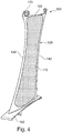
Figure 4 is a schematic showing a finished hollow aerofoil manufactured in accordance with the method of the present disclosure; -
Figure 5 is a flowchart showing an example of a method for manufacturing a hollow aerofoil in accordance with the method of the present disclosure; and -
Figure 6 is a schematic showing a fixture containing multiple intermediate aerofoil assemblies. - Aspects and embodiments of the present disclosure will now be discussed with reference to the accompanying figures. Further aspects and embodiments will be apparent to those skilled in the art.
- With reference to
Figure 1 , a ducted fan gas turbine engine generally indicated at 10 has a principal and rotational axis X-X. The direction X-X may be referred to as the axial direction of the engine. Theengine 10 comprises, in axial flow series, anair intake 11, apropulsive fan 12, anintermediate pressure compressor 13, a high-pressure compressor 14,combustion equipment 15, a high-pressure turbine 16, anintermediate pressure turbine 17, a low-pressure turbine 18 and a coreengine exhaust nozzle 19. A nacelle generally surrounds theengine 10 and defines theintake 11, abypass duct 22 and abypass exhaust nozzle 23. - The
gas turbine engine 10 works in a conventional manner so that air entering theintake 11 is accelerated by thefan 12 to produce two air flows: a first air flow A into theintermediate pressure compressor 13 and a second airflow B (which may be referred to as a bypass flow B) which passes through thebypass duct 22 to provide propulsive thrust. Theintermediate pressure compressor 13 compresses the air flow A directed into it before delivering that air to thehigh pressure compressor 14 where further compression takes place. - The compressed air exhausted from the high-
pressure compressor 14 is directed into thecombustion equipment 15 where it is mixed with fuel and the mixture combusted. The resultant hot combustion products then expand through, and thereby drive the high, intermediate and low-pressure turbines nozzle 19 to provide additional propulsive thrust. The high, intermediate and low-pressure turbines intermediate pressure compressors fan 12 by suitable interconnecting shafts. Other gas turbine engines to which the present disclosure may be applied may have different configurations, for example having two shafts, three shafts and/or a gearbox through which thefan 12 is linked to a turbine. - The
gas turbine engine 10 comprises outlet guide vanes (OGVs) 100 extending across thebypass duct 22, which therefore sit in the bypass flow B. EachOGV 100 takes the form of a large stator vane, and thus may be referred to as an aerofoil oraerofoil component 100. A plurality ofOGVs 100 is typically provided as an annular array in thebypass duct 22. - Because each
OGV 100 is an especially large aerofoil component, it is particularly advantageous to reduce its weight. Thus, theOGV 100 in thegas turbine engine 10 is hollow. -
Figure 5 is a flowchart showing an example method for manufacturing (or forming) a hollow aerofoil, such as the OGV/aerofoil 100 shown inFigure 1 , and is described below in conjunction withFigures 2 to 4 . - The method starts with a step S10 of providing a first panel, which may be the
first panel 200 shown inFigure 2 . As shown inFigure 2 , asecond panel 300 is also provided. In step S20, thesecond panel 300 is laid over thefirst panel 200. This may alternatively be described as bringing thefirst panel 200 and thesecond panel 300 together, as illustrated by arrows A and B inFigure 2 . Thefirst panel 200 andsecond panel 300 may be any suitable material, for example metallic (such as titanium), and may be the same or different materials. - A bonding material (for example an activated diffusion bonding material or a braze material) 400 is provided at one or more regions between the two
panels bonding material 400 may define joining regions of the twopanels bonding material 400 may be provided to one or both of thepanels bonding material 400 between the joining regions may actually be performed before the step of laying thesecond panel 300 over at least a part of thefirst panel 200. - The
bonding material 400 may be provided in any desired location between thefirst panel 200 and thesecond panel 300. For example, thefirst panel 200 and/or thesecond panel 300 may be "oversized" in that their major surfaces (i.e. largest surfaces) are bigger than thepressure surface 120 andsuction surface 110 of theaerofoil 100 being formed (seeFigure 4 ). In that case, thebonding material 400 may be positioned so as to define the leading edge 130 (from aleading edge portion 430 of the bonding material 400) and/or trailing edge 140 (from a trailing edge portion 440 of the bonding material 400) and/or tip 150 (from a tip portion 450 of the bonding material 450) of thefinished aerofoil 100. - The
bonding material 400 may be provided in any suitable form, such as a foil. By way of example, the bonding material may be an activateddiffusion bonding material 400, in the form of a CuNi foil. Also by way of example, thecapping panel 200 and the pocketedaerofoil body 300 shown inFigure 3 may be titanium. - Other arrangements of
first panel 200,second panel 300, andbonding material 400 are also within the scope of the present disclosure. For example, thefirst panel 200 may have a recess into which thesecond panel 300 is inserted. In such an arrangement, thebonding material 400 may be formed around at least a portion of the perimeter of the recess. - The
first panel 200 may comprise aroot portion 230, as in theFigure 2 example. Such aroot portion 230 may subsequently be aroot 160 of thefinished aerofoil 100 that is used to attach thefinished aerofoil 100 to agas turbine engine 10. As shown inFigure 4 , thefinished vane 100 may comprisefixtures fixtures first panel 200 orsecond panel 300 before they are brought together for bonding and hot forming, or one or both of thesefixtures -
Figure 3 shows the twopanels aerofoil sub-assembly 700 prior to being put into arig 600, in step s40 (shown by the arrow inFigure 3 as well as the flowchart inFigure 5 ). Although not visible inFigure 3 , the twopanels bonding material 400 provided therebetween in the joining region. The two panels may be temporarily held together before the bonding step, for example usingtack welds 500 as in theFigure 3 example. - Once loaded into the
rig 600, thesub-assembly 700 is subjected to a bonding step and a hot forming step S50. As noted elsewhere herein, the bonding step and the hot forming step may overlap and/or may be a combined bonding and hot forming step. For the avoidance of doubt, the claims and description provided elsewhere herein in relation to the bonding step and the hot forming step may apply to any arrangement, including (but not limited to) the examples described in relation to the Figures. - Where the bonding step is an activated diffusion bonding step, it comprises raising the temperature of the sub-assembly 700 to a bonding temperature. At the bonding temperature, the
first panel 200 and thesecond panel 300 join together in the region of theactivation material 400. Theactivation material 400 acts to lower the melting point of the material to which it is adjacent, and thus of the adjacent material of thefirst panel 200 and thesecond panel 300. As described elsewhere herein, the bonding temperature may be chosen to be a temperature at which the material of thefirst panel 200 andsecond panel 300 adjacent theactivation material 400 melts, but remains substantially unaffected in regions away from theactivation material 400. The temperature in therig 600 may be maintained at or near to the bonding temperature for sufficient time for theactivation material 400 to diffuse through theparts panels - Purely by way of non-limitative example, the temperature in the
rig 600 may be maintained at around 920 degrees C for around 30 minutes from the start of the bonding step. The temperature may then be reduced to around 900 degrees C and held at that temperature over the immediately subsequent 60 minutes, thereby completing the hot forming step. The total time elapsed between the start of the bonding step and the end of the hot forming step may be less than two hours, for example. In the illustrated example, thesub-assembly 700 is not removed from therig 600 from the start of the bonding step to the end of the hot forming step. In other words, after the sub-assembly 700 is put into therig 600, it is not removed until after the bonding step and hot forming step are complete. - If the
panels hollow aerofoil 100 in the region of the join may be indistinguishable (including substantially indistinguishable) from the surrounding material. This means that the material in the region of the join has the same properties (for example in terms of strength and/or melting point) as the original material of thefirst panel 200 and the second 300 (at least where the first andsecond panels first panel 200 and thesecond panel 300, the material properties at the join may gradually change from those of thefirst panel 200 to those of thesecond panel 300. - During the hot forming step, the outer surfaces of the
panels pressure surface 120 andsuction surface 110 of thefinished aerofoil 100. This may be achieved, for example, by hot creep forming, for example into a mould. Additionally or alternatively, the hot forming step may comprise hot blow forming to form thepressure surface 120 and/or suction surface. - The bonding and hot forming steps S50 may be performed for
individual sub-assemblies 700 separately or at the same time.Figure 6 shows, in schematic form, multipleintermediate sub-assemblies 700 arranged in a box fixture 600 (which is one example of arig 600 described and/or claimed herein). Thesub-assemblies 700 are suspended from a top (or roof)surface 610 of thebox fixture 600 in theFigure 6 example. Thesub-assemblies 700 shown inFigure 6 are suspended with their longitudinal axes (i.e. the axis extending substantially from the root to the tip, along the span of the aerofoil) aligned with the vertical (i.e. aligned with gravity). The temperature and/or pressure in thebox fixture 600 may be varied as required to perform the bonding and hot forming steps, for example as described and/or claimed elsewhere herein. - It will be appreciated that the
aerofoil 100 being formed could be any suitable component, such as any stator vane for use in a turbine or compressor of a gas turbine engine. Purely by way of example theaerofoil 100 may be an outlet guide vane (OGV), as illustrated by way of example inFigure 1 . - It will be appreciated that many designs and/or arrangements of features - such as
first panel 200,second panel 300, and method steps S10-S50 - other than those shown in and described in relation toFigures 1 to 6 and not explicitly described herein fall within the scope of the present disclosure as set out in the appended claims. Furthermore, any feature described and/or claimed herein may be combined with any other compatible feature described in relation to the same or another embodiment.
Claims (15)
- A method of forming a hollow aerofoil (100) for a gas turbine engine (10), the aerofoil having a pressure surface (120) and a suction surface (110), the method comprising the steps of:providing a first panel (200);laying a second panel (300) over at least a part of the first panel;providing a bonding material (400) between a joining region of the first panel and a joining region of the second panel to form an aerofoil sub-assembly (700);loading the aerofoil sub-assembly (700) into a forming rig (600) and performing a bonding step in which the temperature of the first panel (200), second panel (300), and bonding material (400) is raised to a bonding temperature at which the first and second panels are joined together; andperforming a hot forming step to generate the shape of the pressure surface (120) and suction surface (110);wherein the hot forming step and bonding step are performed in the same forming rig (600).
- The method according to claim 1, wherein the bonding step and the hot forming step are performed without removing the panels (200, 300) from the forming rig (600).
- The method according to claim 1 or 2, wherein the bonding step overlaps with the hot forming step.
- The method according to any preceding claim, wherein the temperature throughout the bonding step and the hot forming step remains within a 50 degree C range.
- The method according to any preceding claim, wherein the temperature in the forming rig (600) from starting the bonding step and finishing the hot forming step remains between 870 degrees C and 950 degrees C.
- The method according to any preceding claim, wherein the total time elapsed between starting the bonding step and finishing the hot forming step is less than 2 hours.
- The method according to any preceding claim, wherein the temperature in the hot forming rig (600) is held at around 920 degrees C from the start of the bonding step for 30 minutes, then reduced to and held at around 900 degrees C over the immediately subsequent 60 minutes, thereby completing the hot forming step.
- The method according to any preceding claim, further comprising applying a stop-off material outside the joining regions that prevents bonding between the first and second panels (200, 300).
- The method according to any preceding claim, wherein the first panel (200) and/or the second panel (300) comprise titanium.
- The method according to any preceding claim, wherein the bonding step is an activated diffusion bonding step, the bonding material is an activated diffusion bonding material that acts to locally reduce the melting point of the first and second panels (200, 300) at the respective joining regions, and, at the bonding temperature, the first and second panels are joined together through activated diffusion bonding between the respective joining regions.
- The method according to any preceding claim, wherein the bonding step comprises brazing and the bonding material is a braze material.
- The method according to claim 11, wherein the braze temperature of the braze material is within 50 degrees of the temperature of the hot forming step.
- The method according to any preceding claim, further comprising forming an interim weld (500) between the first panel (200) and the second panel (300) when forming the aerofoil sub-assembly (700).
- The method according to any preceding claim, wherein one of the first panel (200) and the second panel (300) comprises a recess into which the other of the first panel and the second panel is placed when forming the aerofoil sub-assembly (700).
- The method according to any preceding claim, wherein the first and second panels (200, 300) are bigger than the final formed aerofoil (100); and the method further comprises a finishing step in which an edge region is removed to produce at least the leading and/or trailing edges (130, 140) of the aerofoil (100).
Applications Claiming Priority (1)
| Application Number | Priority Date | Filing Date | Title |
|---|---|---|---|
| GBGB1809111.6A GB201809111D0 (en) | 2018-06-04 | 2018-06-04 | Manufacture of a hollow aerofoil |
Publications (1)
| Publication Number | Publication Date |
|---|---|
| EP3578277A1 true EP3578277A1 (en) | 2019-12-11 |
Family
ID=62872746
Family Applications (1)
| Application Number | Title | Priority Date | Filing Date |
|---|---|---|---|
| EP19172893.0A Withdrawn EP3578277A1 (en) | 2018-06-04 | 2019-05-07 | Method of forming a hollow aerofoil |
Country Status (3)
| Country | Link |
|---|---|
| US (1) | US11684997B2 (en) |
| EP (1) | EP3578277A1 (en) |
| GB (1) | GB201809111D0 (en) |
Families Citing this family (1)
| Publication number | Priority date | Publication date | Assignee | Title |
|---|---|---|---|---|
| US20220388090A1 (en) * | 2021-06-04 | 2022-12-08 | The Boeing Company | Fabrication of thick stock via diffusion bonding of titanium alloys |
Citations (8)
| Publication number | Priority date | Publication date | Assignee | Title |
|---|---|---|---|---|
| US4526312A (en) * | 1979-12-10 | 1985-07-02 | Rockwell International Corporation | Low cost method of making superplastically formed and diffusion bonded structures |
| EP0468221A2 (en) * | 1990-06-27 | 1992-01-29 | Compressor Components Textron Inc. | Method of making hollow articles |
| EP0549172A1 (en) * | 1991-12-09 | 1993-06-30 | General Electric Company | Design and processing method for manufacturing hollow airfoils (three-piece concept) |
| US5297937A (en) * | 1991-08-23 | 1994-03-29 | Mitsubishi Jukogyo Kabushiki Kaisha | Hollow fan moving blade |
| US5469618A (en) * | 1993-12-06 | 1995-11-28 | General Electric Company | Method for manufacturing hollow airfoils (two-piece concept) |
| GB2306353A (en) | 1995-10-28 | 1997-05-07 | Rolls Royce Plc | A method of manufacturing a blade |
| US20020174540A1 (en) | 2001-05-26 | 2002-11-28 | Milburn Richard G. | Method of manufacturing an article |
| US20040018091A1 (en) | 2002-07-26 | 2004-01-29 | Rongong Jem A. | Turbomachine blade |
Family Cites Families (3)
| Publication number | Priority date | Publication date | Assignee | Title |
|---|---|---|---|---|
| GB0100695D0 (en) | 2001-01-11 | 2001-02-21 | Rolls Royce Plc | a turbomachine blade |
| US7419086B2 (en) * | 2003-07-14 | 2008-09-02 | Honeywell International Inc. | Low cost brazes for titanium |
| GB0318937D0 (en) * | 2003-08-13 | 2003-09-17 | Rolls Royce Plc | A method of manufacturing an article by diffusion bonding and superplastic forming |
-
2018
- 2018-06-04 GB GBGB1809111.6A patent/GB201809111D0/en not_active Ceased
-
2019
- 2019-05-07 EP EP19172893.0A patent/EP3578277A1/en not_active Withdrawn
- 2019-05-22 US US16/419,281 patent/US11684997B2/en active Active
Patent Citations (8)
| Publication number | Priority date | Publication date | Assignee | Title |
|---|---|---|---|---|
| US4526312A (en) * | 1979-12-10 | 1985-07-02 | Rockwell International Corporation | Low cost method of making superplastically formed and diffusion bonded structures |
| EP0468221A2 (en) * | 1990-06-27 | 1992-01-29 | Compressor Components Textron Inc. | Method of making hollow articles |
| US5297937A (en) * | 1991-08-23 | 1994-03-29 | Mitsubishi Jukogyo Kabushiki Kaisha | Hollow fan moving blade |
| EP0549172A1 (en) * | 1991-12-09 | 1993-06-30 | General Electric Company | Design and processing method for manufacturing hollow airfoils (three-piece concept) |
| US5469618A (en) * | 1993-12-06 | 1995-11-28 | General Electric Company | Method for manufacturing hollow airfoils (two-piece concept) |
| GB2306353A (en) | 1995-10-28 | 1997-05-07 | Rolls Royce Plc | A method of manufacturing a blade |
| US20020174540A1 (en) | 2001-05-26 | 2002-11-28 | Milburn Richard G. | Method of manufacturing an article |
| US20040018091A1 (en) | 2002-07-26 | 2004-01-29 | Rongong Jem A. | Turbomachine blade |
Non-Patent Citations (1)
| Title |
|---|
| LYUSHINSKII A V: "DIFFUSION BONDING THROUGH INTERLAYERS BASED ON MIXTURES OF ULTRADISPERSE METAL POWDERS. ÖPART 1 PRODUCTION OF INTERLAYERS BASED ON ULTRADISPERSE POWDERS OFNICKEL, COPPER AND COBALT", WELDING INTERNATIONAL, TAYLOR & FRANCIS, ABINGDON, GB, vol. 7, no. 12, 1 January 1993 (1993-01-01), pages 974 - 979, XP000415908, ISSN: 0950-7116 * |
Also Published As
| Publication number | Publication date |
|---|---|
| US11684997B2 (en) | 2023-06-27 |
| US20190366470A1 (en) | 2019-12-05 |
| GB201809111D0 (en) | 2018-07-18 |
Similar Documents
| Publication | Publication Date | Title |
|---|---|---|
| US11602809B2 (en) | Processes and tooling associated with diffusion bonding the periphery of a cavity-back airfoil | |
| US8408446B1 (en) | Methods and tooling assemblies for the manufacture of metallurgically-consolidated turbine engine components | |
| EP3064715B1 (en) | Airfoil for a gas turbine and fabrication method | |
| EP2947266B1 (en) | Methods of repairing integrally bladed rotors | |
| US20160311052A1 (en) | Manufacture of a hollow aerofoil | |
| EP2047945A1 (en) | Method of manufacturing a turbine rotor and corresponding turbine rotor | |
| US20190040744A1 (en) | Power beam welded cavity-back titanium hollow fan blade | |
| US9879545B2 (en) | Manufacture of hollow aerofoil | |
| JP2012026448A (en) | Components with bonded edges | |
| RU2607389C2 (en) | Method of metal part producing | |
| EP3067153A1 (en) | Manufacture of a hollow aerofoil | |
| EP2851509B1 (en) | Manufacture of hollow aerofoil | |
| US11684997B2 (en) | Manufacture of a hollow aerofoil | |
| US20080120842A1 (en) | Rotary machine components and methods of fabricating such components | |
| EP2412930A2 (en) | Turbine nozzle segment and method of repairing same | |
| EP3279434B1 (en) | Cooled gas turbine engine component with baffles | |
| US11400515B2 (en) | Method of manufacturing a component using a sinter joining process | |
| EP3927943B1 (en) | Tip repair of a turbine component using a composite tip boron base pre-sintered preform | |
| US10828718B2 (en) | Installation of waterjet vent holes into vertical walls of cavity-back airfoils | |
| US11819966B2 (en) | Repair methods and systems for honeycomb structures in gas turbine engines | |
| GB2587644A (en) | Diffusion bonded vane | |
| EP3685959A1 (en) | A method of forming a protective sheath for an aerofoil component | |
| US20200030882A1 (en) | Method for manufacturing a structural component for a turbomachine | |
| US20190381608A1 (en) | Installation of laser vent holes into vertical walls of cavity-back airfoils |
Legal Events
| Date | Code | Title | Description |
|---|---|---|---|
| PUAI | Public reference made under article 153(3) epc to a published international application that has entered the european phase |
Free format text: ORIGINAL CODE: 0009012 |
|
| STAA | Information on the status of an ep patent application or granted ep patent |
Free format text: STATUS: THE APPLICATION HAS BEEN PUBLISHED |
|
| AK | Designated contracting states |
Kind code of ref document: A1 Designated state(s): AL AT BE BG CH CY CZ DE DK EE ES FI FR GB GR HR HU IE IS IT LI LT LU LV MC MK MT NL NO PL PT RO RS SE SI SK SM TR |
|
| AX | Request for extension of the european patent |
Extension state: BA ME |
|
| RAP1 | Party data changed (applicant data changed or rights of an application transferred) |
Owner name: ROLLS-ROYCE PLC |
|
| STAA | Information on the status of an ep patent application or granted ep patent |
Free format text: STATUS: THE APPLICATION IS DEEMED TO BE WITHDRAWN |
|
| 18D | Application deemed to be withdrawn |
Effective date: 20200613 |