EP3577802B1 - Method and apparatus for time-controlled data transmission in a tsn - Google Patents
Method and apparatus for time-controlled data transmission in a tsn Download PDFInfo
- Publication number
- EP3577802B1 EP3577802B1 EP17711599.5A EP17711599A EP3577802B1 EP 3577802 B1 EP3577802 B1 EP 3577802B1 EP 17711599 A EP17711599 A EP 17711599A EP 3577802 B1 EP3577802 B1 EP 3577802B1
- Authority
- EP
- European Patent Office
- Prior art keywords
- time
- source
- network element
- sink
- network
- Prior art date
- Legal status (The legal status is an assumption and is not a legal conclusion. Google has not performed a legal analysis and makes no representation as to the accuracy of the status listed.)
- Active
Links
Images

Classifications
-
- H—ELECTRICITY
- H04—ELECTRIC COMMUNICATION TECHNIQUE
- H04J—MULTIPLEX COMMUNICATION
- H04J3/00—Time-division multiplex systems
- H04J3/02—Details
- H04J3/06—Synchronising arrangements
- H04J3/0635—Clock or time synchronisation in a network
- H04J3/0638—Clock or time synchronisation among nodes; Internode synchronisation
- H04J3/0658—Clock or time synchronisation among packet nodes
- H04J3/0661—Clock or time synchronisation among packet nodes using timestamps
- H04J3/0667—Bidirectional timestamps, e.g. NTP or PTP for compensation of clock drift and for compensation of propagation delays
-
- H—ELECTRICITY
- H04—ELECTRIC COMMUNICATION TECHNIQUE
- H04J—MULTIPLEX COMMUNICATION
- H04J3/00—Time-division multiplex systems
- H04J3/02—Details
- H04J3/06—Synchronising arrangements
- H04J3/0635—Clock or time synchronisation in a network
- H04J3/0638—Clock or time synchronisation among nodes; Internode synchronisation
- H04J3/0652—Synchronisation among time division multiple access [TDMA] nodes, e.g. time triggered protocol [TTP]
-
- H—ELECTRICITY
- H04—ELECTRIC COMMUNICATION TECHNIQUE
- H04J—MULTIPLEX COMMUNICATION
- H04J3/00—Time-division multiplex systems
- H04J3/02—Details
- H04J3/06—Synchronising arrangements
- H04J3/0635—Clock or time synchronisation in a network
- H04J3/0638—Clock or time synchronisation among nodes; Internode synchronisation
- H04J3/0658—Clock or time synchronisation among packet nodes
- H04J3/0673—Clock or time synchronisation among packet nodes using intermediate nodes, e.g. modification of a received timestamp before further transmission to the next packet node, e.g. including internal delay time or residence time into the packet
-
- H—ELECTRICITY
- H04—ELECTRIC COMMUNICATION TECHNIQUE
- H04J—MULTIPLEX COMMUNICATION
- H04J3/00—Time-division multiplex systems
- H04J3/02—Details
- H04J3/06—Synchronising arrangements
- H04J3/0635—Clock or time synchronisation in a network
- H04J3/0682—Clock or time synchronisation in a network by delay compensation, e.g. by compensation of propagation delay or variations thereof, by ranging
-
- H—ELECTRICITY
- H04—ELECTRIC COMMUNICATION TECHNIQUE
- H04J—MULTIPLEX COMMUNICATION
- H04J3/00—Time-division multiplex systems
- H04J3/02—Details
- H04J3/06—Synchronising arrangements
- H04J3/0635—Clock or time synchronisation in a network
- H04J3/0685—Clock or time synchronisation in a node; Intranode synchronisation
- H04J3/0697—Synchronisation in a packet node
-
- H—ELECTRICITY
- H04—ELECTRIC COMMUNICATION TECHNIQUE
- H04L—TRANSMISSION OF DIGITAL INFORMATION, e.g. TELEGRAPHIC COMMUNICATION
- H04L47/00—Traffic control in data switching networks
- H04L47/10—Flow control; Congestion control
- H04L47/22—Traffic shaping
-
- H—ELECTRICITY
- H04—ELECTRIC COMMUNICATION TECHNIQUE
- H04L—TRANSMISSION OF DIGITAL INFORMATION, e.g. TELEGRAPHIC COMMUNICATION
- H04L47/00—Traffic control in data switching networks
- H04L47/10—Flow control; Congestion control
- H04L47/24—Traffic characterised by specific attributes, e.g. priority or QoS
- H04L47/2416—Real-time traffic
-
- H—ELECTRICITY
- H04—ELECTRIC COMMUNICATION TECHNIQUE
- H04L—TRANSMISSION OF DIGITAL INFORMATION, e.g. TELEGRAPHIC COMMUNICATION
- H04L47/00—Traffic control in data switching networks
- H04L47/50—Queue scheduling
- H04L47/56—Queue scheduling implementing delay-aware scheduling
- H04L47/564—Attaching a deadline to packets, e.g. earliest due date first
- H04L47/566—Deadline varies as a function of time spent in the queue
-
- H—ELECTRICITY
- H04—ELECTRIC COMMUNICATION TECHNIQUE
- H04J—MULTIPLEX COMMUNICATION
- H04J3/00—Time-division multiplex systems
- H04J3/02—Details
- H04J3/06—Synchronising arrangements
- H04J3/0635—Clock or time synchronisation in a network
- H04J3/0685—Clock or time synchronisation in a node; Intranode synchronisation
- H04J3/0694—Synchronisation in a TDMA node, e.g. TTP
Definitions
- TSN Time Sensitive Networking, IEEE 802.1
- IEEE 802.1 The extensions of the IEEE working group TSN (Time Sensitive Networking, IEEE 802.1) enable real-time communication in networks that work according to the Ethernet standard.
- the current IEEE standards for TSN which are currently being developed, particularly take into account the requirements of the automotive industry and controls in automation systems with their requirements for the networks with regard to real-time behavior.
- Mechanisms and protocols are defined in order to be able to offer deterministic services for time-sensitive streaming through a network according to the Ethernet standard.
- Time-Aware-Shaper is defined in the IEEE 802.1Qbv standard and can protect scheduled, scheduled data transfer from disruptions from other data traffic by using fixed time windows and thus achieving a deterministic low latency. If the so-called "cut-through" routing is offered in combination with TAS, the best real-time performance can be achieved with the lowest latency and the lowest delay variance.
- TAS network for a scheduled data transfer requires that all network elements, i.e. both the switching stations / bridges and the end user stations, are time-synchronized so that the TAS time windows are scheduled on the same time base.
- TAS windows depends on the global network information, for example on the network topology, and therefore requires a fully managed network. Because of the high planning and administrative effort and inefficient use of bandwidth for the remaining data traffic, these networks are, for example, already PROFINET IRT (Isochrounous Real Time) network, mainly used for hard real-time systems and motion control applications that place the highest demands on real-time capability and reliability. For those real-time systems that do not require these highest requirements with the lowest latency, other traffic flow regulations with less planning effort than TAS are preferred, as long as the required determinism is offered.
- PROFINET IRT Isochrounous Real Time
- CBS Credit-Based Shaper
- AVB uses the Stream Reservation Protocol (SRP), which is defined in IEEE 802.1Qat, for the reservation of resources in the network for each individual AVB stream, calculated on the basis of a worst-case delay and with a memory requirement calculated for the bridges based on Traffic Classes.
- SRP Stream Reservation Protocol
- the worst-case delay per network element (bridge) in CBS is topology-dependent and the same dependency is found in the memory requirement. This means that the worst-case analysis becomes very complex and depends on the topology. Inaccurate worst-case calculations lead to incorrect reservations in the network, either too many resources are occupied. The more problematic case, however, would be the insufficient reservation, which leads to unexpected data loss due to insufficiently dimensioned bridge memory. which ultimately causes serious errors in the real-time system.
- CQF Cyclic Queuing and Forwarding
- latency Min H - 1 * T
- the transmission jitter for CQF is 2T, which is a fixed value, regardless of the number of hops in the transmission link.
- CQF achieves a deterministic latency and a topology-independent jitter, but for the price of increased latency in the best case as a result of the waiting time forced by the shaper in each bridge.
- the duration T of the time intervals must be selected large enough to accommodate all data in a given class measurement interval, plus an interference frame of maximum size with lower priority. If the frame preemption defined in IEEE 802.1bu / 802.3.3br is combined with CQF, then the maximum size of an interference fragment can be further reduced to the size of a maximum frame fragment. This means that more stream data can be reserved for the same interval duration T for use with CQF if preemption is used.
- CQF is superior to CBS in terms of technology independence and the simplicity of calculating worst-case latency in the worst case, CQF needs it also a cyclical time sequence that requires a time-synchronized network as a basis.
- CQF is implemented with PSFP (perstream filtering and policing, IEEE 802.1Qi) and TAS (IEEE 802.QBv)
- PSFP perstream filtering and policing, IEEE 802.1Qi
- TAS IEEE 802.QBv
- the traffic classes are a limited resource of a bridge (with an IEEE 802.1Q-compliant bridge there is a maximum of 8), the need for two queues per traffic class is seen as a disadvantage of the CQF.
- the second weak point of CQF is the need for time synchronization.
- a data transmission method is known, for example for the 3G HSDPA protocols (HARQ, 3GPP TS 25.308), which takes the delay into account during data transmission, accumulates this information over the transmission path and, depending on the information during transmission, uses a suitable transmission protocol to maintain a desired transmission time.
- 3G HSDPA protocols HARQ, 3GPP TS 25.308
- the method concerns the time-controlled data transmission of data packets in a time-sensitive network according to the TSN standard.
- the network consists of individual network elements and the time lapse in each network element is divided into pre-planned, equally large time windows.
- the network elements each have their own independent timer and these time windows begin and end at the same points in time for all network elements.
- a data packet is transmitted from a first network element to a subsequent network element in the time window which follows the time window in which this data packet was received by a preceding network element.
- Each network element determines, based on its own independent timer and a delay value, at what point in time the next transmission window begins and / or ends.
- a new traffic shaping method for time-sensitive data streams is described, which is also called “Packet Delay Variation Compensation (PDVC)" in the following.
- the aim is to offer the same real-time performance and configuration complexity as CQF, but without the need for time synchronization of the entire network.
- the PDVC Shaper also ensures that a data frame that is received by a bridge in a first time interval is passed on to the next hop / bridge by this bridge in the next time interval.
- a major difference to CQF is how these time intervals are implemented in the bridges.
- CQF realizes the intervals in the bridge in a certain way by using a cyclical network-central timer and forms the streams of a given transport class based on the same schedule (a sequence of successive time intervals).
- the cyclic timer of the CQF Bridges in the network must run on a common time base so that the time intervals can be synchronized to the same start time.
- Each bridge knows the start time of the time interval that belongs to a certain data stream. This is defined by the source of the stream, (StreamID), by tracking the timing of each frame on each hop along the data path from source to sink.
- StreamID source of the stream
- Each data frame must contain a so-called “delay value”, i.e. a delay value that is measured by each bridge using a local clock that measures the delay time the data frame spends in the queue at the outgoing port.
- the measured delay value should deduct any delay caused by the PDVC Shaper and reflect how the actual transmission time AT deviates from the planned transmission time.
- Eligilibility Time ET The planned transmission time for a data frame, usually referred to as Eligilibility Time ET, is determined by the PDVC Shaper at the earliest possible point in time when the data frame is entered in the queue of the output transmission port.
- T is the class measurement interval which belongs to the stream of this data frame and represents the transmission interval of the stream at its source.
- T is the class measurement interval which belongs to the stream of this data frame and represents the transmission interval of the stream at its source.
- PDVC determines the ET for a data frame on the current bridge, based on the delay information of the data frame on the previous hop.
- Such a shaping approach is based on the information from the previous hop and is also referred to as "route based traffic shaping".
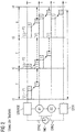
- Figure 1 shows an example of the procedure according to the invention, using the PDVC Shaper for the transmission of a single data stream from the source source through 2 bridges B1, B2 to a data sink, sink.
- Each of these network elements has its own timer C1 to C4, which is self-sufficient and not synchronized with one of the other time sources.
- the data source periodically generates a frame P1, P2, P3, P4 at times t1, t2, t3, t4, with a constant time interval T between times t1 to t4.
- the start time of the respective time interval is shown in the figure by a dashed vertical line.
- the data packets in dashed lines show the time at which the packet is scheduled to be sent, the packets with a solid line below the respective time line t of the respective network element then the actual time at which the packet is sent - ideally in the same time window.
- each subsequent receiving bridge B1, B2 realign the time of the transmission of the data frame.
- the transfer time is calculated using the formula for ET (i + 1) from above.
- CD denotes an additional constant delay per jump.
- PDVC must be used on all bridges B1, B2 along the data transmission path, as well as in the data sources, if these Data sources also generate other data traffic that conflicts with the first data traffic and delays the planned transmission in time.
- the maximum delay per bridge and the maximum end-to-end latency of PDVC are similar to CQF because of the dependence on the interval T and the number of hops h.
- PDVC via bridge delay ⁇ 2T per hop delivery jitter 2T H - 1 * T ⁇ PDVC end-to-end latency ⁇ H * T
- the above limit values are calculated under the condition of Formula 2 that the value of T is always less than any possible value of (DV (i) + CD) that can occur.
- the same conditions apply to CQF for the selection of T by taking into account the maximum amount of stream data observed during the time interval T plus a maximally large disturbing data frame.
- the combined use of frame preemption and PDVC helps reduce the number of possible stream data for a fixed time interval T, or the time interval T for the same amount of stream data, resulting in reduced worst-case latency.
- the traffic shaper described here offers a similarly good real-time performance with fixed maximum latency and fixed delivery jitter as CQF. This performance is required in a large number of industrial applications and controls that do not have the highest demands on real-time.
- the greatest advantage compared to the standardized solution is that the solution can do without a time-synchronized network such as PTP IEEE 1588 or IEEE 802.1AS and thus save the costs otherwise required.
- the main method that is used is the so-called traffic shaping in order to obtain a deterministic performance, which forces a delay for every data frame at every hop to ensure that the periodic stream traffic through the network with a fixed per-hop delay.
- PDVC makes these decisions based on previous hop information, which is measured using local clocks and is transmitted from bridge to bridge in every frame .
Description
Durch die Erweiterungen der IEEE Arbeitsgruppe TSN (Time Sensitive Networking, IEEE 802.1) wird Echtzeitkommunikation in Netzwerken, die gemäß Ethernet Standard arbeiten, ermöglicht. Die aktuellen, sich in Entwicklung befindenden IEEE Standards für TSN berücksichtigen besonders die Anforderungen der Automobilindustrie und Steuerungen in Automatisierungsanlagen mit ihren Anforderungen an die Netzwerke bezüglich Echtzeitverhalten. Es werden Mechanismen und Protokolle definiert, um deterministische Dienste anbieten zu können für das zeitsensitives Streaming durch ein Netzwerk gemäß Ethernet Standard.The extensions of the IEEE working group TSN (Time Sensitive Networking, IEEE 802.1) enable real-time communication in networks that work according to the Ethernet standard. The current IEEE standards for TSN, which are currently being developed, particularly take into account the requirements of the automotive industry and controls in automation systems with their requirements for the networks with regard to real-time behavior. Mechanisms and protocols are defined in order to be able to offer deterministic services for time-sensitive streaming through a network according to the Ethernet standard.
Der sogenannte Time-Aware-Shaper (TAS) ist im Standard IEEE 802.1Qbv definiert und kann zeitlich vorgeplanten, geschedulten Datentransfer vor Störungen aus anderem Datenverkehr schützen, indem festgelegte Zeitfenster verwendet werden und so eine deterministische niedrige Latenz erreicht wird. Falls das sogenannte "cut-through" Routing in Kombination mit TAS angeboten wird, so kann die beste Echtzeit-Leistungsfähigkeit mit niedrigster Latenz und geringsten Verzögerungs-Varianz erreicht werden.
Ein TAS Netzwerk für einen geschedulten Datentransfer anzuwenden erfordert, dass alle Netzelemente, also sowohl die Vermittlungsstationen / Bridges als auch die Endteilnehmerstationen zeitsynchronisiert sind, so dass die TAS-Zeitfenster auf derselben Zeitbasis gescheduled werden.The so-called Time-Aware-Shaper (TAS) is defined in the IEEE 802.1Qbv standard and can protect scheduled, scheduled data transfer from disruptions from other data traffic by using fixed time windows and thus achieving a deterministic low latency. If the so-called "cut-through" routing is offered in combination with TAS, the best real-time performance can be achieved with the lowest latency and the lowest delay variance.
Using a TAS network for a scheduled data transfer requires that all network elements, i.e. both the switching stations / bridges and the end user stations, are time-synchronized so that the TAS time windows are scheduled on the same time base.
Das Scheduling von TAS Fenstern hängt von der globalen Netzinformation ab, beispielsweise von der Netzwerk-Topologie, und benötigt daher ein vollständig verwaltetes Netzwerk. Wegen des hohen Planungs- und Verwaltungsaufwands und ineffizienter Bandbreiten-Ausnutzung für den verbleibenden Datenverkehr werden diese Netze, so wie beispielsweise bereits PROFINET IRT (Isochrounous Real Time) Netz, hauptsächlich für Harte Echtzeitsysteme und Motion-Control-Anwendungen verwendet, die höchste Anforderungen an die Echtzeitfähigkeit und Zuverlässigkeit stellen.
Für solche Echtzeit-Systeme, die nicht diese höchsten Anforderungen mit niedrigster Latenz fordern, werden andere Verkehrsflußregelungen mit weniger Planungsaufwand als TAS bevorzugt, solange der benötigte Determinismus angeboten wird.The scheduling of TAS windows depends on the global network information, for example on the network topology, and therefore requires a fully managed network. Because of the high planning and administrative effort and inefficient use of bandwidth for the remaining data traffic, these networks are, for example, already PROFINET IRT (Isochrounous Real Time) network, mainly used for hard real-time systems and motion control applications that place the highest demands on real-time capability and reliability.
For those real-time systems that do not require these highest requirements with the lowest latency, other traffic flow regulations with less planning effort than TAS are preferred, as long as the required determinism is offered.
Der sogenannte Credit-Based Shaper (CBS), wurde in dem IEEE Standard 802.1Qav von der AVB (Audio-Video-Bridging) Task Group definiert und ist vorgesehen für Audio-Video Streams mit begrenzter Latenz und Verlustfreiheit bei Datenstau. CBS glättet den Datentransfer der Streams durch gleichmäßige Verteilung der Datenpakete über die Zeit. Die Idee dahinter ist, die Konzentration von Datenframes zu verhindern, was eine Überlastung der Datenpuffer der Bridges zur Folge haben könnte und damit den Verlust von Datenframes. Die Begrenzung der Konzentration hat den Vorteil, dass der in den Bridges benötigte Daten-Puffer am Ausgangsport kleiner dimensioniert sein kann und einen niedrigeren maximalen Delay im Ausgangs-Stream der Bridge erzeugt.The so-called Credit-Based Shaper (CBS) was defined in the IEEE Standard 802.1Qav by the AVB (Audio-Video-Bridging) Task Group and is intended for audio-video streams with limited latency and freedom from loss in the event of data congestion. CBS smooths the data transfer of the streams by evenly distributing the data packets over time. The idea behind this is to prevent the concentration of data frames, which could overload the data buffers of the bridges and result in the loss of data frames. Limiting the concentration has the advantage that the data buffer required in the bridges can be dimensioned smaller at the output port and creates a lower maximum delay in the output stream of the bridge.
AVB verwendet das Stream-Reservation Protokoll (SRP), das in IEEE 802.1Qat definiert ist, für die Reservierung von Ressourcen im Netzwerk für jeden einzelnen AVB Stream, kalkuliert auf Basis eines Worst-case Delays und mit einem Speicherbedarf berechnet für die Bridges basierend auf Traffic Classes.
Es stellt sich jedoch heraus, dass der Worst-Case Delay pro Netzelement (Bridge) bei CBS topologieabhängig ist und dieselbe Abhängigkeit findet sich beim Speicherbedarf. Das führt dazu, dass die Worst-Case Analyse sehr komplex wird und topologieabhängig ist. Ungenaue Worst-Case Berechnungen führen zu falschen Reservierungen im Netzwerk, es werden entweder zu viele Ressourcen belegt. Der jedoch problematischere Fall wäre die zu geringe Reservierung, die zu unerwarteten Datenverlusten führt aufgrund zu gering dimensionierter Bridge Speicher, was letztendlich ernsthafte Fehler im Echtzeit-System verursacht.AVB uses the Stream Reservation Protocol (SRP), which is defined in IEEE 802.1Qat, for the reservation of resources in the network for each individual AVB stream, calculated on the basis of a worst-case delay and with a memory requirement calculated for the bridges based on Traffic Classes.
However, it turns out that the worst-case delay per network element (bridge) in CBS is topology-dependent and the same dependency is found in the memory requirement. This means that the worst-case analysis becomes very complex and depends on the topology. Inaccurate worst-case calculations lead to incorrect reservations in the network, either too many resources are occupied. The more problematic case, however, would be the insufficient reservation, which leads to unexpected data loss due to insufficiently dimensioned bridge memory. which ultimately causes serious errors in the real-time system.
Zur Vermeidung der oben beschriebenen Probleme wurde ein weiteres Protokoll definiert, das Cyclic Queuing and Forwarding (CQF) Protocol, IEEE 802.1Qch. Es bietet eine Flußkontrolle mit garantierter maximaler Latenz und einer begrenzten Verzögerungsschwankung pro Sprung (sogenannter fixed delivery Jitter an jeder Bridge im Netzwerk). Das Senden von Datenpaketen gemäß CQF Protokoll wird exemplarisch in
Da bei CQF jeder Datenframe von einer Bridge im Laufe des aktuellen Intervalls genau um einen Hop im Pfad weiter übertragen wird, ist die Verzögerung pro Hop begrenzt auf zweimal die Länge des Zeitintervalls T, der Worst-case Delay.
Die maximale Latenz für die Übertragung eines Frames in dem Netz ist also ![]()
So the maximum latency for the transmission of a frame in the network is![]()
Wenn ein Frame bei jedem Hop immer zu Anfang des nächsten Frames und ohne weitere Verzögerung durch störenden Datenverkehr übertragen wird, abgesehen von der Verzögerung die durch einen Shaper im Netz verursacht wird, dann ist die minimale Latenz wie folgt zu berechnen: ![]()
![]()
Der Übertragungsjitter beträgt bei CQF die Zeitdauer 2T, welches ein fester Wert ist, unabhängig von der Anzahl der Hops in der Übertragungsstrecke. CQF erreicht eine deterministische Latenz und einen topologie-unabhängigen Jitter jedoch für den Preis einer erhöhten Latenz im besten Fall als Resultat von der durch den Shaper erzwungenen Wartezeit in jeder Bridge.The transmission jitter for CQF is 2T, which is a fixed value, regardless of the number of hops in the transmission link. CQF achieves a deterministic latency and a topology-independent jitter, but for the price of increased latency in the best case as a result of the waiting time forced by the shaper in each bridge.
Der größte Vorteil von CQF im Vergleich zu CBS ist die massiv reduzierte Komplexität in der Berechnung der worst-case Verzögerung wegen der fehlenden Abhängigkeit von der Netzwerk-Topologie. Der festgelegte Jitter der CQF Traffic Class führt zu gleichmäßig verteilten Speichergrößen in den CQF Warteschlangen (Queues) aller Bridges, was einen verallgemeinernden Ansatz im Ressourcen-Berechnungsmodell erlaubt, der geeignet ist für jedes mögliche CQF Szenario.The greatest advantage of CQF compared to CBS is the massively reduced complexity in the calculation of the worst-case delay due to the lack of dependency on the network topology. The specified jitter of the CQF traffic class leads to evenly distributed memory sizes in the CQF queues of all bridges, which allows a generalizing approach in the resource calculation model that is suitable for every possible CQF scenario.
Um sicherzustellen, dass die oben berechneten Latenzgrenzen erreicht werden können, muss die Dauer T der Zeitintervalle groß genug gewählt werden um allen Daten in einem vorgegebenen Klassen-Messintervall Platz zu bieten, plus einem Stör-Frame maximaler Größe von niedrigerer Priorität.
Wenn die in IEEE 802.1bu/802.3.3br definierte Frame Preemption mit CQF kombiniert wird, dann kann die maximale Größe eines Stör-Fragments weiter reduziert werden auf die Größe eines maximalen Frame-Fragments. Das bedeutet, dass für die gleiche Intervalldauer T für die Verwendung mit CQF mehr Streamdata reserviert werden kann, wenn Preemption verwendet wird.To ensure that the latency limits calculated above can be achieved, the duration T of the time intervals must be selected large enough to accommodate all data in a given class measurement interval, plus an interference frame of maximum size with lower priority.
If the frame preemption defined in IEEE 802.1bu / 802.3.3br is combined with CQF, then the maximum size of an interference fragment can be further reduced to the size of a maximum frame fragment. This means that more stream data can be reserved for the same interval duration T for use with CQF if preemption is used.
Obwohl CQF gegenüber CBS bezüglich der Technologie-Unabhängigkeit und der Einfachheit der Berechnung der Worst-Case Latenz im ungünstigsten Fall überlegen ist, benötigt CQF ebenfalls einen zyklischen Zeitablauf das als Basis ein zeitsynchronisiertes Netzwerk benötigt. Wenn CQF mit PSFP (perstream filtering and policing, IEEE 802.1Qi) und TAS (IEEE 802.QBv) implementiert wird, dann werden von CQF am AusgangsPort zwei Transport-Klasse Warteschlangen pro Datenstream benötigt für eine einzelne SR (Stream Reservation) Class. Die zwei Warteschlangen werden zyklisch abwechselnd verwendet mit Hilfe von Input und Output Gate Control um sicherzustellen, dass die eine Warteschlange im Puffer-Status arbeitet und die andere im Übertragungs-Modus. Weil die Traffic Classes eine begrenzte Ressource einer Bridge sind (bei einer IEEE 802.1Q konformen Bridge sind es maximal 8), wird der Bedarf von zwei Warteschlangen pro Traffic Class als Nachteil der CQF angesehen. Der zweite Schwachpunkt von CQF ist, wie bereits erwähnt, die Notwendigkeit einer Zeitsynchronisierung.Although CQF is superior to CBS in terms of technology independence and the simplicity of calculating worst-case latency in the worst case, CQF needs it also a cyclical time sequence that requires a time-synchronized network as a basis. If CQF is implemented with PSFP (perstream filtering and policing, IEEE 802.1Qi) and TAS (IEEE 802.QBv), then CQF needs two transport class queues per data stream for a single SR (Stream Reservation) class at the output port. The two queues are cyclically used alternately with the help of input and output gate control to ensure that one queue works in buffer status and the other in transfer mode. Because the traffic classes are a limited resource of a bridge (with an IEEE 802.1Q-compliant bridge there is a maximum of 8), the need for two queues per traffic class is seen as a disadvantage of the CQF. The second weak point of CQF, as already mentioned, is the need for time synchronization.
Aus der
Es ist daher Aufgabe der Erfindung, ein Verfahren und eine Vorrichtung anzugeben, zur Übertragung von zeitkritischen Datenpaketen mit einer garantierten maximalen Latenz, eine topologie-unabhängige Latenz-Kalkulation und eine begrenzte Schwankung der Verzögerungen (delay), ohne zentrale Zeitsynchronisation im Netz und/oder in den Endgeräten.It is therefore the object of the invention to specify a method and a device for the transmission of time-critical data packets with a guaranteed maximum latency, a topology-independent latency calculation and a limited fluctuation in the delays (delay), without central time synchronization in the network and / or in the end devices.
Die Aufgabe wird gelöst durch je ein Verfahren und eine Vorrichtung mit den Merkmalen der unabhängigen Patentansprüche.The object is achieved by a method and a device each having the features of the independent claims.
Das Verfahren betrifft die zeitgesteuerte Datenübertragung von Datenpaketen in einem time-sensitiven Netzwerk gemäß TSN Standard. Das Netzwerk besteht dabei aus einzelnen Netzelementen und der Zeitablauf ist in jedem Netzelement eingeteilt in vorgeplante, gleichgroße Zeitfenster.
Die Netzelemente verfügen jeweils über einen eigenen unabhängigen Zeitmesser und diese Zeitfenster beginnen und enden bei allen Netzelementen zu den gleichen Zeitpunkten. Die Übertragung eines Datenpakets von einem ersten Netzelement zu einem darauffolgenden Netzelement erfolgt in dem Zeitfenster, welches dem Zeitfenster folgt, in dem dieses Datenpaket von einem vorhergehenden Netzelement empfangen wurde.
Jedes Netzelement bestimmt dann basierend auf dem durch eigenen unabhängigen Zeitmesser und einem Verzögerungswert, zu welchem Zeitpunkt das nächste Sendefenster beginnt und/oder endet.The method concerns the time-controlled data transmission of data packets in a time-sensitive network according to the TSN standard. The network consists of individual network elements and the time lapse in each network element is divided into pre-planned, equally large time windows.
The network elements each have their own independent timer and these time windows begin and end at the same points in time for all network elements. A data packet is transmitted from a first network element to a subsequent network element in the time window which follows the time window in which this data packet was received by a preceding network element.
Each network element then determines, based on its own independent timer and a delay value, at what point in time the next transmission window begins and / or ends.
Weitere vorteilhafte Ausführungsformen der Erfindung sind durch die Merkmale der Unteransprüche angegeben.Further advantageous embodiments of the invention are indicated by the features of the subclaims.
Beschrieben wird eine neue Traffic Shaping Methode für zeitsensitive Datenstreams, die im Folgenden auch "Packet Delay Variation Compensation (PDVC)" genant wird. Es ist das Ziel, die gleiche Echtzeit-Performanz und Konfigurations-Komplexität zu bieten wie CQF aber ohne die Notwendigkeit einer Zeitsynchronisierung des kompletten Netzwerks.
Der PDVC Shaper sorgt ebenfalls dafür, dass ein Datenframe, der durch eine Bridge in einem ersten Zeitintervall empfangen wird, durch diese Bridge in dem nächsten Zeitintervall an den nächstliegenden Hop/Bridge weiter gereicht wird.
Ein wesentlicher Unterschied zu CQF besteht darin, wie diese Zeitintervalle in den Bridges realisiert werden. CQF realisiert die Intervallen in der Bridge in einer bestimmten Weise durch Verwendung von einem zyklischen Netz-zentralen Timer und formt die Streams einer vorgegebenen Transport-Klasse basierend auf demselben Schedule (eine Abfolge von aufeinander folgenden Zeitintervallen). Der zyklische Timer der CQF Bridges im Netzwerk muss dabei auf einer gemeinsamen Zeitbasis laufen, damit die Zeitintervalle auf die gleiche Startzeit synchronisiert werden können.A new traffic shaping method for time-sensitive data streams is described, which is also called "Packet Delay Variation Compensation (PDVC)" in the following. The aim is to offer the same real-time performance and configuration complexity as CQF, but without the need for time synchronization of the entire network.
The PDVC Shaper also ensures that a data frame that is received by a bridge in a first time interval is passed on to the next hop / bridge by this bridge in the next time interval.
A major difference to CQF is how these time intervals are implemented in the bridges. CQF realizes the intervals in the bridge in a certain way by using a cyclical network-central timer and forms the streams of a given transport class based on the same schedule (a sequence of successive time intervals). The cyclic timer of the CQF Bridges in the network must run on a common time base so that the time intervals can be synchronized to the same start time.
Das hier beschriebene Verfahren kommt ohne die im Verfahren gemäß dem Stand der Technik unverzichtbare zentrale Zeitbasis aus. Jede Bridge kennt die Startzeit des Zeitintervalls, das zu einem bestimmten Datenstream gehört. Dieser ist durch die Quelle des Streams definiert, (StreamID), durch Verfolgung des Zeitablaufs jedes Frames an jedem Hop entlang des Datenpfads von der Quelle zur Senke. Jeder Datenframe muss einen sogenannten "Delay Wert" enthalten, also einen Verzögerungswert, der durch jede Bridge gemessen wird unter Verwendung einer lokalen Uhr die die Verzögerungszeit misst, die der Datenframe in der Warteschlange am ausgehenden Port verbringt. Abhängig von der Implementierung sollte der gemessene Delay Wert jeden Delay herausrechnen, der durch den PDVC Shaper verursacht wird, und widerspiegelt, wie die tatsächliche Übertragungszeit AT abweicht von der geplanten Übertragungszeit. Die geplante Übertragungszeit für einen Datenframe, üblicherweise als Eligilibility Time ET bezeichnet, wird vom PDVC Shaper zum frühest möglichen Zeitpunkt ermittelt, wenn der Daten-Frame in der Wartenschlage des Ausgangsübertragungs-ports eingetragen wird.
Der Verzögerungswert, Delay Value DV, der an der Bridge gemessen wird, berechnet sich wie folgt: ![]()
The delay value, Delay Value DV, which is measured at the bridge, is calculated as follows:![]()
Wenn die nächste Bridge im Übertragungspfad i+1 einen Datenframe mit DV(i) erhält, dann berechnet es ET(i+1) für den Datenframe ![]()
![]()
CD ist ein Verzögerungswert bestehend aus den folgenden Komponenten, die abhängig von der Hardware und Framegrößenspezifisch sind:
- Der Verzögerungswert des Datenframes (delay) gemessen von AT(i), welches die tatsächliche Startzeit der Datenübertragung am Ausgangsport der Bridge i zum Zeitpunkt wenn der vollständige Datenframe beim Eingangsport der nächstfolgenden Bridge i+1 empfangen wurde. Der Hauptteil dieses Verzögerungswerts kann in Bridge i+1 einfach berechnet werden basierend auf der Geschwindigkeit des Übertragungslinks und der Framegröße. Der verbleibende Teil ist abhängig von der Hardware, inclusive dem Verzögerungswert des Kabels (link propagation delay) zwischen der sendenden Bridge i und der empfangenden Bridge i+1, der ebenfalls durch das Netzmanagement festgelegt oder durch Messungen durch ein Zeitsynchronisierungsprotokoll ermittelt werden, beispielswese gPTP of 802.1AS, sofern geeignet.
- Der Verzögerungswert des Vermittlungsvorgangs in der Bridge i+1, üblicherweise handelt es sich hier um einen festen Wert, der sich in der Hardware Spezifikation der Bridge findet.
- The delay value of the data frame (delay) measured by AT (i), which is the actual start time of the data transmission at the output port of the bridge i at the time when the complete data frame was received at the input port of the next bridge i + 1. The majority of this delay value can easily be calculated in Bridge i + 1 based on the speed of the transmission link and the frame size. The remaining part depends on the hardware, including the delay value of the cable (link propagation delay) between the sending bridge i and the receiving bridge i + 1, which is also determined by the network management or determined by measurements using a time synchronization protocol, e.g. gPTP of 802.1AS if applicable.
- The delay value of the switching process in the bridge i + 1, usually a fixed value that can be found in the hardware specification of the bridge.
Wie in der zweiten Formel angedeutet, stellt PDVC den ET für einen Datenframe auf der aktuellen Bridge fest, basierend auf der Verzögerungsinformation des Datenframes am vorherigen Hop. Solch ein Shaping-Ansatz basiert auf der Information aus dem vorhergehenden Hop, und wird auch als "Route based Traffic Shaping" bezeichnet.As indicated in the second formula, PDVC determines the ET for a data frame on the current bridge, based on the delay information of the data frame on the previous hop. Such a shaping approach is based on the information from the previous hop and is also referred to as "route based traffic shaping".
Im Folgenden wird die Erfindung durch Figuren erläutert.
-
Figur 1 -
Figur 2
-
Figure 1 the inventive procedure and -
Figure 2 shows the procedure according to the prior art.
Wie dargestellt, generiert die Datenquelle, Source, periodisch einen Frame P1, P2, P3, P4 zu den Zeitpunkten t1, t2, t3, t4 wobei zwischen den Zeitpunkten t1 bis t4 jeweils ein gleichbleibendes Zeitintervall T liegt. Der Startzeitpunkt des jeweiligen Zeitintervalls ist in der Figur durch eine gestrichelte senkrechte Linie dargestellt. Die Datenpakete in gestrichelten Linien zeigen den Zeitpunkt, an dem das Paket geplant abgesendet werden soll, die Pakete mit durchgezogener Linie unterhalb der jeweiligen Zeitlinie t des jeweiligen Netzelementes dann den tatsächlichen Zeitpunkt, an dem das Paket - optimalerweise im selben Zeitfenster - abgesendet wird. Mit der Hilfe vom Verzögerungswert DV0, DV1, DV2, der durch den Aufenthalt in der ausgehenden Warteschlange des Ausgangsports der jeweiligen Netzelemente entsteht, der bei jedem Hop gemessen wird und als zusätzliches Datenfeld im Frame mit zum nächsten Netzelement übertragen wird, kann jede darauffolgende empfangende Bridge B1, B2 den Zeitpunkt der Übertragung des Datenframes zeitlich neu ausrichten. Der Übertragungszeitpunkt berechnet sich dabei gemäß der Formel für ET(i+1) von oben.
CD bezeichnet einen zusätzlichen konstanten Delay pro Sprung. Dieses Feature von PDVC ist vorteilhaft für die Kontrollanwendung, wo eine Anzahl von Streams in das Netzwerk aus verschiedenen Datenquellen zu verschiedenen Zeitpunkten in einer koordinierten Art und Weise. PDVC kann die gleichen Übertragungsreihenfolgen bei allen Streams beim Ausgangsport jeder Bridge entlang des Datenübertragungspfads.As shown, the data source, source, periodically generates a frame P1, P2, P3, P4 at times t1, t2, t3, t4, with a constant time interval T between times t1 to t4. The start time of the respective time interval is shown in the figure by a dashed vertical line. The data packets in dashed lines show the time at which the packet is scheduled to be sent, the packets with a solid line below the respective time line t of the respective network element then the actual time at which the packet is sent - ideally in the same time window. With the help of the delay value DV0, DV1, DV2, which is created by staying in the outgoing queue of the output port of the respective network element, which is measured with each hop and transmitted as an additional data field in the frame to the next network element, each subsequent receiving bridge B1, B2 realign the time of the transmission of the data frame. The transfer time is calculated using the formula for ET (i + 1) from above.
CD denotes an additional constant delay per jump. This feature of PDVC is advantageous for the control application where a number of streams enter the network from different data sources at different points in time in a coordinated manner. PDVC can use the same transmission order for all streams at the output port of each bridge along the data transmission path.
Um sicherzustellen, dass PDVC korrekt arbeitet, muss PDVC auf allen Bridges B1, B2 entlang des Datenübertragungspfades angewendet werden, ebenso wie in den Datenquellen, wenn diese Datenquellen außerdem noch anderen Datenverkehr erzeugen, welcher sich mit dem ersten Datenverkehr in Konflikt befindet und die geplante Übertragung zeitlich verzögern.
Die maximale Verzögerung pro Bridge und die maximale End-to-End Latenz von PDVC sind ähnlich zu CQF wegen der Abhängigkeit von dem Intervall T und der Anzahl der Hops h.To ensure that PDVC works correctly, PDVC must be used on all bridges B1, B2 along the data transmission path, as well as in the data sources, if these Data sources also generate other data traffic that conflicts with the first data traffic and delays the planned transmission in time.
The maximum delay per bridge and the maximum end-to-end latency of PDVC are similar to CQF because of the dependence on the interval T and the number of hops h.
PDVC per bridge Delay < 2T
per Hop delivery Jitter = 2T ![]()
per hop delivery jitter = 2T![]()
Die oben genannten Grenzwerte sind berechnet unter der Bedingung von Formel 2, dass der Wert von T immer kleiner als jeder möglicher Wert von (DV(i) + CD), der auftreten kann. Um sicherzustellen, dass die Bedingung immer erfüllt wird, gelten dieselben Bedingungen bei CQF für die Auswahl von T durch Berücksichtigung der maximalen Menge von Stream Daten, die während dem Zeitintervall T beobachtet plus einen maximal großen störenden Datenframe. Ähnlich zu CQF hilft eine kombinierte Verwendung von Frame Preemption und PDVC die Anzahl der möglichen Streamdata für ein festes Zeitintervall T, oder das Zeitintervall T verkleinern für dieselbe Menge von Streamdaten resultierend in einer reduzierten Worst-Case Latenz.The above limit values are calculated under the condition of
In dem Beispiel von
Der hier beschriebene Traffic Shaper bietet eine ähnlich gute Echtzeit-Performanz mit fester maximaler Latenz und festem Delivery Jitter wie CQF. Diese Leistungsfähigkeit wird in einer Vielzahl von Industrieanwendungen und -Steuerungen benötigt, die nicht allerhöchste Anforderungen an die Echtzeit stellen. Der größte Vorteil gegenüber der standardisierten Lösung ist, dass die Lösung auf ein zeitsynchronisiertes Netz wie PTP IEEE 1588 oder IEEE 802.1AS verzichten und damit die dafür sonst benötigten Kosten sparen kann.The traffic shaper described here offers a similarly good real-time performance with fixed maximum latency and fixed delivery jitter as CQF. This performance is required in a large number of industrial applications and controls that do not have the highest demands on real-time. The greatest advantage compared to the standardized solution is that the solution can do without a time-synchronized network such as PTP IEEE 1588 or IEEE 802.1AS and thus save the costs otherwise required.
Die Hauptmethode die zur Anwendung kommt ist das sogenannte Traffic Shaping um eine deterministische Leistung zu erhalten, die einen Delay für jeden Datenframe bei jedem Hop erzwingt, um so sicherzustellen dass der periodische Stream Traffic durch das Netz mit einer festen per-hop Verzögerung. Anders als bei CQF, das den Wert der Shaper-bedingten Verzögerung basierend auf einem globalen Timer berechnet, trifft PDVC diese Entscheidungen basierend auf vorangegangener Hop-Information, die gemessen wird mit Hilfe von lokalen Uhren, und in jedem Frame von Bridge zu Bridge übertragen wird.The main method that is used is the so-called traffic shaping in order to obtain a deterministic performance, which forces a delay for every data frame at every hop to ensure that the periodic stream traffic through the network with a fixed per-hop delay. Unlike CQF, which calculates the value of the shaper-related delay based on a global timer, PDVC makes these decisions based on previous hop information, which is measured using local clocks and is transmitted from bridge to bridge in every frame .
Claims (7)
- Method for the time-controlled data transmission of data packets (P1, P2, P3, P4) in a time-sensitive network in accordance with the TSN standard, wherein- each data packet is assigned to a data stream and is identified by a unique stream ID,- the network consists of individual network elements (Source, B1, B2, Sink), and- the time sequence (t) in each network element (Source, B1, B2, Sink) is divided into pre-scheduled, equal-sized time windows (T) and- the network elements (Source, B1, B2, Sink) each have their own independent timer (C1, C2, C3, C4) which is not synchronized with timers of other network elements, and- these time windows for all network elements start and end at the same time points (t1, t2, t3, t4),characterized in that the transmission of a data packet (P1, P2, P3, P4) from a first network element (Source, B1, B2) to a subsequent network element (B1, B2, Sink) takes place in the time window following the time window in which this data packet (P1, P2, P3, P4) was received by a preceding network element (Source, B1, B2), and
each network element (Source, B1, B2, Sink) knows the start time of the time window belonging to a data stream,
each network element (Source, B1, B2, Sink) determines, based on its own independent timer (C1, C2, C3, C4) which is not synchronized with timers of other network elements and a delay value (DVi), at what time point (t1, t2, t3, t4) the next transmit time window begins and/or ends, and
the required delay value (DVi) is calculated in the transmitting network element (Source, B1, B2) depending on the associated data stream and is transmitted in the data packet (P1, P2, P3, P4) to the receiving network element (B1, B2, Sink). - Method according to Patent Claim 1,
characterized in that
the delay value (DVi) is calculated from the actual transmission time AT(i) minus the scheduled transmission time ET (i) . - Method according to one of the preceding patent claims,
characterized in that
the scheduled transmission time is calculated in the next transmission step ET(i+1) by the measurement interval T - (delay time DV(i) plus an additional delay value (CD)). - Method according to one of the preceding patent claims,
characterized in that
for determining the delay value (CD) the transmission time for the data packet (P1, P2, P3, P4) is determined by determining- the duration of the transmission using the start time of the data transmission at the transmitting network element (Source, B1, B2) until the complete reception of the data packet at the receiving network element (B1, B2, Sink) plus a hardware-dependent time delay component and- the duration of the switching process in the network element (Source, B1, B2, Sink). - Method according to Patent Claim 4,
characterized in that
the durations are determined in advance by a time synchronization protocol. - Network element (Source, B1, B2, Sink) which is configured to be operated in a time-sensitive network in accordance with the TSN standard, wherein
the network consists of individual network elements (Source, B1, B2, Sink), and- the time sequence (t) in each network element (Source, B1, B2, Sink) is divided into pre-scheduled, equal-sized time windows (T), and- the network elements (Source, B1, B2, Sink) each have their own independent timer (C1, C2, C3, C4) which is not synchronized with timers of other network elements, and- these time windows for all network elements start and end at the same time points (t1, t2, t3, t4), and- each data packet (P1, P2, P3, P4) to be transmitted is assigned to a data stream and is identified by a unique stream ID,characterized in that- the network element (Source, B1, B2) is configured to transmit the data packet (P1, P2, P3, P4) to a successive network element (B1, B2, Sink) in the time window which follows the time window in which this data packet (P1, P2, P3, P4) was received by a preceding network element (Source, B1, B2), and each network element (Source, B1, B2, Sink) knows the start time of the time window belonging to a data stream, andthe network element (Source, B1, B2, Sink) determines, based on its own independent timer (C1, C2, C3, C4) which is not synchronized with timers of other network elements and a delay value (DVi), at what time point (t1, t2, t3, t4) the next transmit time window begins and/or ends by
calculating the required delay value (DVi) in the transmitting network element (Source, B1, B2) depending on the associated data stream and transmitting it in the data packet (P1, P2, P3, P4) to the receiving network element (B1, B2, Sink). - Device suitable for implementing the method in accordance with the features of one of Patent Claims 1 to 5.
Applications Claiming Priority (1)
| Application Number | Priority Date | Filing Date | Title |
|---|---|---|---|
| PCT/EP2017/055819 WO2018166576A1 (en) | 2017-03-13 | 2017-03-13 | Method and device for time-controlled data transmission in a tsn |
Publications (2)
| Publication Number | Publication Date |
|---|---|
| EP3577802A1 EP3577802A1 (en) | 2019-12-11 |
| EP3577802B1 true EP3577802B1 (en) | 2020-10-21 |
Family
ID=58358565
Family Applications (1)
| Application Number | Title | Priority Date | Filing Date |
|---|---|---|---|
| EP17711599.5A Active EP3577802B1 (en) | 2017-03-13 | 2017-03-13 | Method and apparatus for time-controlled data transmission in a tsn |
Country Status (4)
| Country | Link |
|---|---|
| US (1) | US11018791B2 (en) |
| EP (1) | EP3577802B1 (en) |
| CN (1) | CN110431769B (en) |
| WO (1) | WO2018166576A1 (en) |
Families Citing this family (24)
| Publication number | Priority date | Publication date | Assignee | Title |
|---|---|---|---|---|
| WO2020165857A1 (en) | 2019-02-14 | 2020-08-20 | Telefonaktiebolaget Lm Ericsson (Publ) | 5g system support for virtual tsn bridge management, qos mapping and tsn qbv scheduling |
| EP3700146A1 (en) | 2019-02-22 | 2020-08-26 | Siemens Aktiengesellschaft | Method for operating a communication system for transferring time-critical data and communication device |
| EP3959847A1 (en) * | 2019-06-25 | 2022-03-02 | Siemens Aktiengesellschaft | Computer-implemented method for adapting at least one predefined frame delay |
| US11463370B2 (en) | 2020-02-12 | 2022-10-04 | Nokia Solutions And Networks Oy | Scalable deterministic services in packet networks |
| CN111327540A (en) * | 2020-02-25 | 2020-06-23 | 重庆邮电大学 | Deterministic scheduling method for industrial time-sensitive network data |
| EP3873009A1 (en) | 2020-02-28 | 2021-09-01 | Siemens Aktiengesellschaft | Method for synchronising control applications over a communications network for transmitting time-critical data, network infrastructure device and communications end device |
| CN111490841A (en) * | 2020-03-23 | 2020-08-04 | 腾讯科技(深圳)有限公司 | Method for realizing time synchronization and related equipment |
| CN111786900B (en) * | 2020-06-15 | 2022-04-29 | 北京交通大学 | Time queue-based temporal sensing flow shaper |
| DE102020207744A1 (en) | 2020-06-23 | 2021-12-23 | Robert Bosch Gesellschaft mit beschränkter Haftung | Method for operating a real-time-based communication system, communication system and communication unit |
| CN112600739B (en) * | 2020-12-31 | 2022-05-31 | 网络通信与安全紫金山实验室 | Vehicle-mounted Ethernet AVB jitter optimization method, system and storage medium |
| CN113206724B (en) * | 2021-03-17 | 2022-03-01 | 西安电子科技大学 | Predictable deterministic scheduling method and device suitable for quasi-dynamic link |
| CN113055303B (en) * | 2021-03-24 | 2022-06-03 | 重庆邮电大学 | Gating scheduling method suitable for multi-cycle application in time-sensitive network |
| CN113572706B (en) * | 2021-06-16 | 2023-02-21 | 燕山大学 | Self-adaptive hierarchical scheduling method for boundary-free cooperative control time-sensitive network |
| CN113542151A (en) * | 2021-06-18 | 2021-10-22 | 新华三大数据技术有限公司 | Traffic scheduling method and device and computer readable storage medium |
| CN115622656A (en) * | 2021-07-12 | 2023-01-17 | 中兴通讯股份有限公司 | Data transmission method and device, network equipment and storage medium |
| CN113612700B (en) * | 2021-08-12 | 2023-11-14 | 北京邮电大学 | Low-delay zero-jitter mixed time sensitive flow scheduling method and device |
| WO2022236194A2 (en) * | 2021-09-08 | 2022-11-10 | Futurewei Technologies, Inc. | Input synchronization for cyclic queueing and forwarding (cqf) |
| CN114338555B (en) * | 2021-11-16 | 2024-02-06 | 北京邮电大学 | Method and device for realizing full-network periodic label planning of wide area deterministic network |
| WO2023108585A1 (en) * | 2021-12-17 | 2023-06-22 | Nokia Shanghai Bell Co., Ltd. | Devices, methods and computer readable media for scheduling optimization for telecommunication systems |
| CN114553782A (en) * | 2022-01-28 | 2022-05-27 | 北京邮电大学 | Network edge based flow shaping scheduling method in large-scale deterministic network |
| CN114553789B (en) * | 2022-02-24 | 2023-12-12 | 昆高新芯微电子(江苏)有限公司 | Method and system for realizing TSN Qci flow filtering function in direct forwarding mode |
| US11870699B1 (en) | 2022-06-27 | 2024-01-09 | Ottopia Technologies Ltd. | Techniques for multi-channel network congestion control |
| DE102022118267B3 (en) | 2022-07-21 | 2024-01-25 | Rockwell Collins Deutschland Gmbh | Synchronized data network system and method for initializing and synchronizing same |
| CN117082002A (en) * | 2023-07-14 | 2023-11-17 | 杭州又拍云科技有限公司 | Circulation data deterministic transmission system and method |
Family Cites Families (7)
| Publication number | Priority date | Publication date | Assignee | Title |
|---|---|---|---|---|
| EP1318632B1 (en) * | 2001-11-24 | 2007-01-03 | Lg Electronics Inc. | Packet data transmission scheduling technique |
| US8634341B1 (en) * | 2005-10-11 | 2014-01-21 | Atmel Corporation | Method and apparatus for iterative synchronization of two or more electronic devices |
| JP2008167141A (en) | 2006-12-28 | 2008-07-17 | Nec Corp | Data transmission method and device, and communication system using the same |
| EP2034642B1 (en) * | 2007-09-07 | 2011-10-26 | Siemens Aktiengesellschaft | Method for transmitting synchronisation messages in a communications network |
| US8416812B2 (en) * | 2008-09-22 | 2013-04-09 | Codrut Radu Radulescu | Network timing synchronization systems |
| EP3633918B1 (en) * | 2011-06-14 | 2021-12-08 | ViaSat, Inc. | Transport protocol for anticipatory content |
| CN106341238A (en) * | 2016-08-10 | 2017-01-18 | 深圳奥尼电子股份有限公司 | Time control device and time control method |
-
2017
- 2017-03-13 WO PCT/EP2017/055819 patent/WO2018166576A1/en active Search and Examination
- 2017-03-13 US US16/492,819 patent/US11018791B2/en active Active
- 2017-03-13 CN CN201780088491.1A patent/CN110431769B/en active Active
- 2017-03-13 EP EP17711599.5A patent/EP3577802B1/en active Active
Non-Patent Citations (1)
| Title |
|---|
| None * |
Also Published As
| Publication number | Publication date |
|---|---|
| CN110431769B (en) | 2021-06-04 |
| CN110431769A (en) | 2019-11-08 |
| US11018791B2 (en) | 2021-05-25 |
| WO2018166576A1 (en) | 2018-09-20 |
| US20200213022A1 (en) | 2020-07-02 |
| EP3577802A1 (en) | 2019-12-11 |
Similar Documents
| Publication | Publication Date | Title |
|---|---|---|
| EP3577802B1 (en) | Method and apparatus for time-controlled data transmission in a tsn | |
| EP3522482B1 (en) | Method for communicating data in an industrial network , control method, device, computer program and computer-readable medium | |
| EP2559221B1 (en) | Method and apparatus for interchanging data, and network | |
| WO2019007516A1 (en) | Method for high-performance data transfer in a data network with, in part, real-time requirements and device for carrying out the method | |
| EP3038325A1 (en) | Method for transmitting data in a communications network of an industrial automation system and coupling communication device | |
| EP3674824B1 (en) | Method for operating a communication system for transferring time-critical data and communication device | |
| EP2832052B1 (en) | Method for transmitting data packets in a communications network and communications network | |
| EP3679691A1 (en) | Data transmission method and communication network | |
| EP2920923B1 (en) | Method and computer network for the transmission of real-time messages | |
| EP1826646B1 (en) | Method, node and network for cyclical transmission of ethernet telegrams | |
| WO2021170343A1 (en) | Method for synchronizing control applications by means of a communication network for transferring time-critical data, network infrastructure device and communication terminal | |
| DE10062640B4 (en) | Method for timing the output of data packets from network nodes, network nodes and configured network | |
| EP3906642B1 (en) | Method for data communication, network nodes and computer program and computer readable medium | |
| EP3629548B1 (en) | Method for transmitting data within an industrial communication network and communication device | |
| EP3758310A1 (en) | Method for data communication, network control device, network, computer program and computer readable medium | |
| EP1453252B1 (en) | Transmission of data in a data switch network | |
| EP3917089A1 (en) | Method for operating a communication system for transferring time-critical data and switch | |
| WO2019016002A1 (en) | Jitter-free data transmission of data packets | |
| EP3518470A1 (en) | Method for communicating data in an industrial network in particular, device for carrying out the method, computer program and computer-readable medium | |
| DE10057651C2 (en) | Process for the production of computerized real-time systems | |
| WO2024003059A1 (en) | Analysing and modelling the jitter and delay behaviour of, in particular, mixed industrial time-sensitive networks | |
| WO2020020579A1 (en) | Method for transferring time-critical data within a communication system for an industrial automation system, and communication system | |
| EP4050856A1 (en) | Method for transmitting time-critical data within a communication system and communication device | |
| EP3905602A1 (en) | Method for operating a communication system for transferring time-critical data and control device | |
| EP3846395A1 (en) | Method for redundant transmission of data streams in a communication network, network infrastructure device and communication terminal |
Legal Events
| Date | Code | Title | Description |
|---|---|---|---|
| STAA | Information on the status of an ep patent application or granted ep patent |
Free format text: STATUS: UNKNOWN |
|
| STAA | Information on the status of an ep patent application or granted ep patent |
Free format text: STATUS: THE INTERNATIONAL PUBLICATION HAS BEEN MADE |
|
| PUAI | Public reference made under article 153(3) epc to a published international application that has entered the european phase |
Free format text: ORIGINAL CODE: 0009012 |
|
| STAA | Information on the status of an ep patent application or granted ep patent |
Free format text: STATUS: REQUEST FOR EXAMINATION WAS MADE |
|
| 17P | Request for examination filed |
Effective date: 20190904 |
|
| AK | Designated contracting states |
Kind code of ref document: A1 Designated state(s): AL AT BE BG CH CY CZ DE DK EE ES FI FR GB GR HR HU IE IS IT LI LT LU LV MC MK MT NL NO PL PT RO RS SE SI SK SM TR |
|
| AX | Request for extension of the european patent |
Extension state: BA ME |
|
| GRAP | Despatch of communication of intention to grant a patent |
Free format text: ORIGINAL CODE: EPIDOSNIGR1 |
|
| STAA | Information on the status of an ep patent application or granted ep patent |
Free format text: STATUS: GRANT OF PATENT IS INTENDED |
|
| DAV | Request for validation of the european patent (deleted) | ||
| DAX | Request for extension of the european patent (deleted) | ||
| INTG | Intention to grant announced |
Effective date: 20200616 |
|
| GRAS | Grant fee paid |
Free format text: ORIGINAL CODE: EPIDOSNIGR3 |
|
| GRAA | (expected) grant |
Free format text: ORIGINAL CODE: 0009210 |
|
| STAA | Information on the status of an ep patent application or granted ep patent |
Free format text: STATUS: THE PATENT HAS BEEN GRANTED |
|
| AK | Designated contracting states |
Kind code of ref document: B1 Designated state(s): AL AT BE BG CH CY CZ DE DK EE ES FI FR GB GR HR HU IE IS IT LI LT LU LV MC MK MT NL NO PL PT RO RS SE SI SK SM TR |
|
| REG | Reference to a national code |
Ref country code: GB Ref legal event code: FG4D Free format text: NOT ENGLISH |
|
| REG | Reference to a national code |
Ref country code: CH Ref legal event code: EP |
|
| REG | Reference to a national code |
Ref country code: IE Ref legal event code: FG4D Free format text: LANGUAGE OF EP DOCUMENT: GERMAN |
|
| REG | Reference to a national code |
Ref country code: AT Ref legal event code: REF Ref document number: 1326906 Country of ref document: AT Kind code of ref document: T Effective date: 20201115 |
|
| REG | Reference to a national code |
Ref country code: DE Ref legal event code: R096 Ref document number: 502017007841 Country of ref document: DE |
|
| REG | Reference to a national code |
Ref country code: NL Ref legal event code: MP Effective date: 20201021 |
|
| PG25 | Lapsed in a contracting state [announced via postgrant information from national office to epo] |
Ref country code: NO Free format text: LAPSE BECAUSE OF FAILURE TO SUBMIT A TRANSLATION OF THE DESCRIPTION OR TO PAY THE FEE WITHIN THE PRESCRIBED TIME-LIMIT Effective date: 20210121 Ref country code: RS Free format text: LAPSE BECAUSE OF FAILURE TO SUBMIT A TRANSLATION OF THE DESCRIPTION OR TO PAY THE FEE WITHIN THE PRESCRIBED TIME-LIMIT Effective date: 20201021 Ref country code: PT Free format text: LAPSE BECAUSE OF FAILURE TO SUBMIT A TRANSLATION OF THE DESCRIPTION OR TO PAY THE FEE WITHIN THE PRESCRIBED TIME-LIMIT Effective date: 20210222 Ref country code: FI Free format text: LAPSE BECAUSE OF FAILURE TO SUBMIT A TRANSLATION OF THE DESCRIPTION OR TO PAY THE FEE WITHIN THE PRESCRIBED TIME-LIMIT Effective date: 20201021 Ref country code: GR Free format text: LAPSE BECAUSE OF FAILURE TO SUBMIT A TRANSLATION OF THE DESCRIPTION OR TO PAY THE FEE WITHIN THE PRESCRIBED TIME-LIMIT Effective date: 20210122 |
|
| REG | Reference to a national code |
Ref country code: LT Ref legal event code: MG4D |
|
| PG25 | Lapsed in a contracting state [announced via postgrant information from national office to epo] |
Ref country code: BG Free format text: LAPSE BECAUSE OF FAILURE TO SUBMIT A TRANSLATION OF THE DESCRIPTION OR TO PAY THE FEE WITHIN THE PRESCRIBED TIME-LIMIT Effective date: 20210121 Ref country code: LV Free format text: LAPSE BECAUSE OF FAILURE TO SUBMIT A TRANSLATION OF THE DESCRIPTION OR TO PAY THE FEE WITHIN THE PRESCRIBED TIME-LIMIT Effective date: 20201021 Ref country code: IS Free format text: LAPSE BECAUSE OF FAILURE TO SUBMIT A TRANSLATION OF THE DESCRIPTION OR TO PAY THE FEE WITHIN THE PRESCRIBED TIME-LIMIT Effective date: 20210221 Ref country code: PL Free format text: LAPSE BECAUSE OF FAILURE TO SUBMIT A TRANSLATION OF THE DESCRIPTION OR TO PAY THE FEE WITHIN THE PRESCRIBED TIME-LIMIT Effective date: 20201021 Ref country code: ES Free format text: LAPSE BECAUSE OF FAILURE TO SUBMIT A TRANSLATION OF THE DESCRIPTION OR TO PAY THE FEE WITHIN THE PRESCRIBED TIME-LIMIT Effective date: 20201021 Ref country code: SE Free format text: LAPSE BECAUSE OF FAILURE TO SUBMIT A TRANSLATION OF THE DESCRIPTION OR TO PAY THE FEE WITHIN THE PRESCRIBED TIME-LIMIT Effective date: 20201021 |
|
| PG25 | Lapsed in a contracting state [announced via postgrant information from national office to epo] |
Ref country code: NL Free format text: LAPSE BECAUSE OF FAILURE TO SUBMIT A TRANSLATION OF THE DESCRIPTION OR TO PAY THE FEE WITHIN THE PRESCRIBED TIME-LIMIT Effective date: 20201021 Ref country code: HR Free format text: LAPSE BECAUSE OF FAILURE TO SUBMIT A TRANSLATION OF THE DESCRIPTION OR TO PAY THE FEE WITHIN THE PRESCRIBED TIME-LIMIT Effective date: 20201021 |
|
| REG | Reference to a national code |
Ref country code: DE Ref legal event code: R097 Ref document number: 502017007841 Country of ref document: DE |
|
| PG25 | Lapsed in a contracting state [announced via postgrant information from national office to epo] |
Ref country code: RO Free format text: LAPSE BECAUSE OF FAILURE TO SUBMIT A TRANSLATION OF THE DESCRIPTION OR TO PAY THE FEE WITHIN THE PRESCRIBED TIME-LIMIT Effective date: 20201021 Ref country code: SK Free format text: LAPSE BECAUSE OF FAILURE TO SUBMIT A TRANSLATION OF THE DESCRIPTION OR TO PAY THE FEE WITHIN THE PRESCRIBED TIME-LIMIT Effective date: 20201021 Ref country code: SM Free format text: LAPSE BECAUSE OF FAILURE TO SUBMIT A TRANSLATION OF THE DESCRIPTION OR TO PAY THE FEE WITHIN THE PRESCRIBED TIME-LIMIT Effective date: 20201021 Ref country code: LT Free format text: LAPSE BECAUSE OF FAILURE TO SUBMIT A TRANSLATION OF THE DESCRIPTION OR TO PAY THE FEE WITHIN THE PRESCRIBED TIME-LIMIT Effective date: 20201021 Ref country code: CZ Free format text: LAPSE BECAUSE OF FAILURE TO SUBMIT A TRANSLATION OF THE DESCRIPTION OR TO PAY THE FEE WITHIN THE PRESCRIBED TIME-LIMIT Effective date: 20201021 Ref country code: EE Free format text: LAPSE BECAUSE OF FAILURE TO SUBMIT A TRANSLATION OF THE DESCRIPTION OR TO PAY THE FEE WITHIN THE PRESCRIBED TIME-LIMIT Effective date: 20201021 |
|
| PLBE | No opposition filed within time limit |
Free format text: ORIGINAL CODE: 0009261 |
|
| STAA | Information on the status of an ep patent application or granted ep patent |
Free format text: STATUS: NO OPPOSITION FILED WITHIN TIME LIMIT |
|
| PG25 | Lapsed in a contracting state [announced via postgrant information from national office to epo] |
Ref country code: DK Free format text: LAPSE BECAUSE OF FAILURE TO SUBMIT A TRANSLATION OF THE DESCRIPTION OR TO PAY THE FEE WITHIN THE PRESCRIBED TIME-LIMIT Effective date: 20201021 |
|
| 26N | No opposition filed |
Effective date: 20210722 |
|
| PG25 | Lapsed in a contracting state [announced via postgrant information from national office to epo] |
Ref country code: AL Free format text: LAPSE BECAUSE OF FAILURE TO SUBMIT A TRANSLATION OF THE DESCRIPTION OR TO PAY THE FEE WITHIN THE PRESCRIBED TIME-LIMIT Effective date: 20201021 Ref country code: IT Free format text: LAPSE BECAUSE OF FAILURE TO SUBMIT A TRANSLATION OF THE DESCRIPTION OR TO PAY THE FEE WITHIN THE PRESCRIBED TIME-LIMIT Effective date: 20201021 Ref country code: MC Free format text: LAPSE BECAUSE OF FAILURE TO SUBMIT A TRANSLATION OF THE DESCRIPTION OR TO PAY THE FEE WITHIN THE PRESCRIBED TIME-LIMIT Effective date: 20201021 |
|
| REG | Reference to a national code |
Ref country code: CH Ref legal event code: PL |
|
| PG25 | Lapsed in a contracting state [announced via postgrant information from national office to epo] |
Ref country code: SI Free format text: LAPSE BECAUSE OF FAILURE TO SUBMIT A TRANSLATION OF THE DESCRIPTION OR TO PAY THE FEE WITHIN THE PRESCRIBED TIME-LIMIT Effective date: 20201021 |
|
| REG | Reference to a national code |
Ref country code: BE Ref legal event code: MM Effective date: 20210331 |
|
| PG25 | Lapsed in a contracting state [announced via postgrant information from national office to epo] |
Ref country code: CH Free format text: LAPSE BECAUSE OF NON-PAYMENT OF DUE FEES Effective date: 20210331 Ref country code: LU Free format text: LAPSE BECAUSE OF NON-PAYMENT OF DUE FEES Effective date: 20210313 Ref country code: LI Free format text: LAPSE BECAUSE OF NON-PAYMENT OF DUE FEES Effective date: 20210331 Ref country code: IE Free format text: LAPSE BECAUSE OF NON-PAYMENT OF DUE FEES Effective date: 20210313 |
|
| PG25 | Lapsed in a contracting state [announced via postgrant information from national office to epo] |
Ref country code: IS Free format text: LAPSE BECAUSE OF FAILURE TO SUBMIT A TRANSLATION OF THE DESCRIPTION OR TO PAY THE FEE WITHIN THE PRESCRIBED TIME-LIMIT Effective date: 20210221 |
|
| PG25 | Lapsed in a contracting state [announced via postgrant information from national office to epo] |
Ref country code: BE Free format text: LAPSE BECAUSE OF NON-PAYMENT OF DUE FEES Effective date: 20210331 |
|
| PGFP | Annual fee paid to national office [announced via postgrant information from national office to epo] |
Ref country code: FR Payment date: 20230317 Year of fee payment: 7 |
|
| REG | Reference to a national code |
Ref country code: AT Ref legal event code: MM01 Ref document number: 1326906 Country of ref document: AT Kind code of ref document: T Effective date: 20220313 |
|
| PG25 | Lapsed in a contracting state [announced via postgrant information from national office to epo] |
Ref country code: CY Free format text: LAPSE BECAUSE OF FAILURE TO SUBMIT A TRANSLATION OF THE DESCRIPTION OR TO PAY THE FEE WITHIN THE PRESCRIBED TIME-LIMIT Effective date: 20201021 |
|
| PG25 | Lapsed in a contracting state [announced via postgrant information from national office to epo] |
Ref country code: HU Free format text: LAPSE BECAUSE OF FAILURE TO SUBMIT A TRANSLATION OF THE DESCRIPTION OR TO PAY THE FEE WITHIN THE PRESCRIBED TIME-LIMIT; INVALID AB INITIO Effective date: 20170313 Ref country code: AT Free format text: LAPSE BECAUSE OF NON-PAYMENT OF DUE FEES Effective date: 20220313 |
|
| PGFP | Annual fee paid to national office [announced via postgrant information from national office to epo] |
Ref country code: DE Payment date: 20230519 Year of fee payment: 7 |
|
| PGFP | Annual fee paid to national office [announced via postgrant information from national office to epo] |
Ref country code: GB Payment date: 20230403 Year of fee payment: 7 |