EP3576829B1 - Intravenous catheter assembly - Google Patents
Intravenous catheter assembly Download PDFInfo
- Publication number
- EP3576829B1 EP3576829B1 EP19715985.8A EP19715985A EP3576829B1 EP 3576829 B1 EP3576829 B1 EP 3576829B1 EP 19715985 A EP19715985 A EP 19715985A EP 3576829 B1 EP3576829 B1 EP 3576829B1
- Authority
- EP
- European Patent Office
- Prior art keywords
- needle
- valve
- catheter
- catheter hub
- hub
- Prior art date
- Legal status (The legal status is an assumption and is not a legal conclusion. Google has not performed a legal analysis and makes no representation as to the accuracy of the status listed.)
- Active
Links
Images


Classifications
-
- A—HUMAN NECESSITIES
- A61—MEDICAL OR VETERINARY SCIENCE; HYGIENE
- A61M—DEVICES FOR INTRODUCING MEDIA INTO, OR ONTO, THE BODY; DEVICES FOR TRANSDUCING BODY MEDIA OR FOR TAKING MEDIA FROM THE BODY; DEVICES FOR PRODUCING OR ENDING SLEEP OR STUPOR
- A61M25/00—Catheters; Hollow probes
- A61M25/01—Introducing, guiding, advancing, emplacing or holding catheters
- A61M25/06—Body-piercing guide needles or the like
- A61M25/0612—Devices for protecting the needle; Devices to help insertion of the needle, e.g. wings or holders
- A61M25/0618—Devices for protecting the needle; Devices to help insertion of the needle, e.g. wings or holders having means for protecting only the distal tip of the needle, e.g. a needle guard
- A61M25/0625—Devices for protecting the needle; Devices to help insertion of the needle, e.g. wings or holders having means for protecting only the distal tip of the needle, e.g. a needle guard with a permanent connection to the needle hub, e.g. a guiding rail, a locking mechanism or a guard advancement mechanism
-
- A—HUMAN NECESSITIES
- A61—MEDICAL OR VETERINARY SCIENCE; HYGIENE
- A61M—DEVICES FOR INTRODUCING MEDIA INTO, OR ONTO, THE BODY; DEVICES FOR TRANSDUCING BODY MEDIA OR FOR TAKING MEDIA FROM THE BODY; DEVICES FOR PRODUCING OR ENDING SLEEP OR STUPOR
- A61M25/00—Catheters; Hollow probes
- A61M25/0097—Catheters; Hollow probes characterised by the hub
-
- A—HUMAN NECESSITIES
- A61—MEDICAL OR VETERINARY SCIENCE; HYGIENE
- A61M—DEVICES FOR INTRODUCING MEDIA INTO, OR ONTO, THE BODY; DEVICES FOR TRANSDUCING BODY MEDIA OR FOR TAKING MEDIA FROM THE BODY; DEVICES FOR PRODUCING OR ENDING SLEEP OR STUPOR
- A61M25/00—Catheters; Hollow probes
- A61M25/01—Introducing, guiding, advancing, emplacing or holding catheters
- A61M25/06—Body-piercing guide needles or the like
- A61M25/0606—"Over-the-needle" catheter assemblies, e.g. I.V. catheters
-
- A—HUMAN NECESSITIES
- A61—MEDICAL OR VETERINARY SCIENCE; HYGIENE
- A61M—DEVICES FOR INTRODUCING MEDIA INTO, OR ONTO, THE BODY; DEVICES FOR TRANSDUCING BODY MEDIA OR FOR TAKING MEDIA FROM THE BODY; DEVICES FOR PRODUCING OR ENDING SLEEP OR STUPOR
- A61M25/00—Catheters; Hollow probes
- A61M25/01—Introducing, guiding, advancing, emplacing or holding catheters
- A61M25/06—Body-piercing guide needles or the like
- A61M25/0612—Devices for protecting the needle; Devices to help insertion of the needle, e.g. wings or holders
-
- A—HUMAN NECESSITIES
- A61—MEDICAL OR VETERINARY SCIENCE; HYGIENE
- A61M—DEVICES FOR INTRODUCING MEDIA INTO, OR ONTO, THE BODY; DEVICES FOR TRANSDUCING BODY MEDIA OR FOR TAKING MEDIA FROM THE BODY; DEVICES FOR PRODUCING OR ENDING SLEEP OR STUPOR
- A61M39/00—Tubes, tube connectors, tube couplings, valves, access sites or the like, specially adapted for medical use
- A61M39/02—Access sites
- A61M39/06—Haemostasis valves, i.e. gaskets sealing around a needle, catheter or the like, closing on removal thereof
Definitions
- the invention generally relates to intravenous catheter assemblies. More particularly, the invention relates to an intravenous catheter assembly comprising a catheter hub arranged at a proximal end of a catheter tube and having an inner space defining a housing; a needle having a needle tip attached to a needle hub having inner space defining a housing and extending through both the housings and the catheter tube when in a ready position.
- IV catheters are used to place a catheter properly into the vascular system of a patient. Once in place, catheters such as intravenous (“IV") catheters may be used to infuse fluids including normal saline, medicinal compounds, and/or nutritional compositions or the like into a patient in need of such treatment. Catheters additionally enable the removal of fluids from the circulatory system and monitoring of conditions within the vascular system of the patient.
- IV intravenous
- peripheral intravenous catheter which are indwelling intravenous catheters often used to provide an entry route for medications, fluid for hydration, and in some cases, for parenteral feeding, into a patient.
- Such catheters are generally short in length, ranging from about one-half to about three inches in length, and are generally made of flexible biocompatible materials.
- Peripheral intravenous catheters are often provided as "over-the-needle" catheters mounted over an introducer needle with a sharp distal tip. A portion of the catheter including at least the distal tip of the catheter securely grips the outside of the needle to prevent catheter peelback during insertion of the catheter into the circulatory system of the patient.
- a septum within the catheter housing can prevent the outflow of fluid during and following removal of the introducer needle.
- These septum structures are generally elastomeric and are designed to closely conform to the shape of a needle during storage and use to prevent leaking, then to seal upon removal of the needle.
- the septum may not completely seal after the needle is removed, having conformed, in part, to the shape of the withdrawn needle.
- An incompletely sealed septum can increase the risk of blood exposure to medical personnel, since blood may flow through the small opening in the slit of the septum. It would thus be an improvement in the art to provide a catheter assembly with more reliable sealing functionality. Such a catheter assembly is disclosed herein.
- WO 2016/142410 A1 discloses a catheter assembly with a valve and a securing ring that is coupled to the valve.
- GB 2 508 466 A discloses a catheter assembly with a valve assembly comprising a first valve portion, wherein the first valve portion comprises a flexible valve disc extending laterally across an internal chamber of a catheter hub.
- US 2013/090609 A1 discloses a catheter assembly with a barrier member comprising one or more slits therethrough.
- a primary object and advantage of the present invention is to provide an improved intravenous catheter assembly which is inexpensive to manufacture, efficient, effective and simple in its construction and use.
- an intravenous catheter assembly comprising: a catheter tube; a catheter hub having a distal section and a proximal section, wherein the distal section is joined to the catheter tube and the proximal section defines a housing; a port provided on the catheter hub forming an opening into the inner space covered by a port cap, a needle extending through the catheter hub and the catheter tube and defining an axial direction, wherein the needle has opposite proximal and distal ends, the distal end forming a needle tip; a needle hub attached to the proximal end of the needle.
- the hub is also provided with wings which in use may be adhesively taped to the skin of the patient at the venipuncture site to maintain the device stationery during the infusion.
- the port in the catheter assembly forms an opening into the inner space which can be covered by a port cap.
- a first valve is provided adjacent to the port opening that provides selective access through the port. Fluid may be infused and withdrawn from the catheter through the port without the problem of leakage/outflow or risk of blood exposure.
- the port forms a first fluid path from the external environment into the inner space of the catheter assembly.
- the first valve provided in the first flow path further provides the ability to infuse and withdraw liquids through the port.
- the valve on or in the port provides a number of benefits when used with blood control-type catheter assemblies.
- the catheter assembly is also provided with a second valve in the inner space which selectively seals a proximal end of the inner space of the catheter housing. Placing the second valve in the catheter hub avoids the problems of outflow of fluid for example, when the second valve is in the path of an introducer needle in the inner space of the catheter hub.
- the second valve is configured with a plug which is also housed in the inner space of the catheter hub.
- the first valve adjacent to the port opening is utilized with a catheter assembly having an internal blood control second valve (also named second valve).
- the second valve can include a blood control septum.
- the blood control septum is provided to allow selective flow of fluid through the fluid pathway.
- the blood control septum may include a slit that may be bypassed when an external luer device is coupled to the hub of the catheter assembly and directly engaging the septum. Upon removing the external luer device, the slit is closed to prevent blood from leaking out of the catheter assembly.
- a septum activator may also be located within the inner space at a location that is behind the second valve.
- the septum activator is advanced forward through the blood control septum of the second valve, activating the blood control septum.
- the septum activator generally comprises a tubular body that is rigid or semi-rigid.
- the tubular body further comprises an inner lumen for facilitating flow of a fluid and/or liquid through the septum activator.
- the distal end of the tubular body can be shaped and sized to compatibly enter within the one or more slits of the blood control septum of the second valve.
- the valves provided can be of various types which can be incorporated into the port and the inner space in the catheter housing to provide medical personnel with the ability to infuse and withdraw fluids from the catheter assembly.
- the valve can be a one-way valve or a two-way valve.
- a two-way valve is a valve that permits fluid flow in two directions through or around the valve when the valve is open.
- Non-limiting examples of a two-way valve include a split septum, a ball valve, and an iris valve or the like.
- a two-way valve can permit fluid to be introduced into the catheter assembly (a first way) and to be withdrawn from the catheter assembly (a second way).
- the valve is a one-way valve, which is a valve that only permits substantial fluid flow in a single direction when the valve is open.
- a non-limiting example of a one-way valve is a check valve.
- the valve can be housed inside the port or in the inner space provided in the housing of the catheter assembly.
- These valve types are not presented as an exhaustive set of valve types, and thus it will be understood that other suitable valves can be utilized in port and the catheter assembly.
- the first valve can be located on a removable luer access connector that can be connected and disconnected from the port.
- the first valve can be located on a luer access connector that is fixedly connected to the port.
- the first valve can be a luer access valve that accommodates the insertion of a luer device, such as those commonly used in the medical industry.
- a body portion of the port can include luer threads or other connecting and/or fastening features that can secure a luer device to the catheter assembly.
- the port can be disposed at an angle relative to the longitudinal axis of the catheter in order to modify the direction at which fluids are infused into the inner housing of the catheter assembly. This angle can be between about 10° to about 90°. The angle of the port can be modified to facilitate use, optimize performance, and/or optimize fluid flow within the inner space of the catheter assembly.
- the embodiments of the present invention may also include the provisions for including a needle guard slidably arranged on the needle, wherein the needle guard is movably retained in the housing of the catheter hub when the needle extends through the catheter hub and the catheter tube, and wherein the needle guard is removable from the catheter hub once the needle tip is received in the needle guard upon withdrawal of the needle from the catheter tube; and wherein the housing defines a chamber at one end thereof ensuring that a first and second arms of the needle guard do not engage or interact with an inner surface of the chamber prior and during venipuncture of a patient.
- An intravenous catheter assembly of this kind is generally known.
- the needle guard serves to prevent a person handling the intravenous catheter apparatus from accidentally coming into contact with the needle tip after placement of the catheter tube in and subsequent removal of the needle from a patient's vein. Thereby, the intravenous catheter assembly helps to avoid unwanted transmission of blood borne diseases.
- the needle may also have a needle feature close to its needle tip, which interacts with a proportional base of the needle guard, e.g. a curving or a bulge or crimp any other change in profile. Thereby, it can be prevented that the needle is retracted out of the needle guard, which is known in the art.
- a proportional base of the needle guard e.g. a curving or a bulge or crimp any other change in profile.
- the catheter hub is made of two parts.
- the first and second parts being joined together define the housing having an inner space.
- the first and second part may form the housing, in particular, the distal end section of the first part and the proximal end section of the second part may form the housing, which ensures that no undercut has to be formed in either one of the first and second part.
- first part includes the port defining a first flow path.
- second part includes the port on the second part.
- the first and second parts of the catheter hub may be joined by complementary end portions, which preferably as such extend at an angle with regard to the axial direction. This ensures that both parts are aligned concentrically towards each other. Thereby, the assembly of such a catheter hub can be made easier.
- end portions may be stepped, which enlarges their contact area for a better mutual interconnection.
- the inner space of the catheter hub may receive a needle guard which is movably arranged on the needle shaft.
- the chamber may be formed by an indentation in the housing for accommodating the first and second arm such that none of the arms deflected by the needle contacts an inner surface of the chamber. Through such indentation the overall outer dimensions of the housing and the catheter hub can be kept small, which it is still provided that the first arm and second arm of the needle guard do not contact the inner wall surface of the chamber.
- the inner space of the housing may be parallel to the axial direction and defined by the distal end section of the first part and the proximal end section of the second part of the catheter hub.
- the inner space of the housing is defined only by one of the first or second part i.e. by either the distal end section of the first part or the proximal end section of the second part.
- the inner space of the housing is defined by the proximal end section of the second part.
- one of the first or second part of the catheter hub comprises a surface joined with the inner surface of the one of the first or second part, which surface is inclined towards the inside of the housing in a proximal direction of the catheter hub, wherein the surface has a smaller inside diameter at its innermost end than a distance between outermost points of the arms in their deflected state inside the chamber.
- the first part comprises the surface joined with the inner surface of the second part.
- the distal end section of the first part comprises the surface joined with the inner surface of the proximal end section of the second part.
- Such a surface serves as a stop for the arms of the needle guard when housed in the inner space of the catheter hub in their deflected state such that they cannot be pulled out of the catheter hub in the proximal axial direction as long as the needle deflects them outward in the ready position of the needle guard.
- the inclination of the surface supports that the arms are directed inwards when the needle guard is pulled out in the retracted position, even if they have been plastically deformed by the needle in their deflected state.
- an antimicrobial coating is applied to one or more surfaces of the intravenous catheter assembly.
- the antimicrobial coating further includes an antimicrobial agent that is compatible for use in intravenous catheter assembly used for infusion therapy.
- suitable antimicrobial agents include chlorhexidine diacetate, chlorhexidine gluconate, alexidine, silver sulfadiazine, silver acetate, silver citrate hydrate, cetrimide, cetyl pyridium chloride, benzalkonium chloride, o-phthalaldehyde, and silver element.
- an intravenous catheter assembly with the features of claim 1, comprising: a catheter tube; a catheter hub having a distal end and a proximal end, wherein the distal end is joined to the catheter tube and the proximal end defines a housing having inner space; a needle extending through the catheter hub and the catheter tube and defining an axial direction (A), wherein the needle has opposite proximal and distal ends, the distal end forming a needle tip; a port extending outwardly in a direction perpendicular to the axial direction (A) from a sidewall of the catheter hub; a needle hub attached to the proximal end of the needle; a first valve provided in the inner space in the catheter hub to prevent foreign contamination from entering the catheter hub; a blood control second valve arranged within the inner space of catheter hub to prevent the outflow of fluid during and following removal of the needle wherein the second valve configured with a plug also housed in the inner space of the catheter hub.
- an intravenous catheter assembly comprising: a catheter tube; a catheter hub having a distal end and a proximal end, wherein the distal end is joined to the catheter tube and the proximal end defines a housing having inner space; a needle extending through the catheter hub and the catheter tube and defining an axial direction (A), wherein the needle has opposite proximal and distal ends, the distal end forming a needle tip; a port extending outwardly in a direction perpendicular to the axial direction (A) from a sidewall of the catheter hub a needle hub attached to the proximal end of the needle having a housing; a needle guard slidably arranged on the needle, wherein the needle guard is movably retained in a needle guard casing and the needle guard casing is movably retained in the housing of the needle hub, when the needle extends through the needle hub, catheter hub and the catheter tube, wherein the needle guard is removable from the needle hub being retained in the
- an intravenous catheter assembly comprising: a catheter tube; a catheter hub having a distal end and a proximal end, wherein the distal end is joined to the catheter tube and the proximal end defines a housing having inner space; a needle extending through the catheter hub and the catheter tube and defining an axial direction (A), wherein the needle has opposite proximal and distal ends, the distal end forming a needle tip; a port extending outwardly in a direction perpendicular to the axial direction (A) from a sidewall of the catheter hub; a needle hub attached to the proximal end of the needle having a housing; a needle guard slidably arranged on the needle and an upper end of the needle guard is securely retained in the housing of the catheter hub exposing the lower end of the needle guard and wherein in the ready to use position, the entire catheter hub portion with the lower end of the needle guard is securely retained in an inner space of the needle hub.
- Some examples of the present invention further comprise one or more methods for manufacturing an intravenous catheter assembly according to the teachings of the instant invention.
- a method of manufacturing comprising the following steps: 1) providing catheter assembly having a catheter hub which has a proximal end, a distal end and an inner space extending therebetween, ; 2) placing a side port on a sidewall of the catheter hub and forming a pathway through the sidewall of the catheter hub and in communication with the inner space: 3) disposing a first valve within the inner space and forming a seal between the inner space and the pathway of the side port 4) disposing a blood control second valve within the inner space and dividing the inner space into a proximal chamber and a distal chamber.
- a further step is provided for providing a needle guard for securely covering the needle tip once withdrawn from the patient in order to prevent accidental pricking.
- the needle guard can be housed in the catheter hub or the needle hub or in part within the catheter hub or in part within the needle hub or in part both within the catheter hub or needle hub or within a needle guard casing.
- a needle guard can be located outside of a catheter hub, such as in a separate hub different from the catheter hub and needle hub.
- the needle guard of the present disclosure may embody any number or type of prior art guards configured for blocking or covering the needle tip of the needle in protected position.
- Some examples of the present invention further comprise a disc arranged proximate to the first valve, the second valve, or both the first and the second valve.
- the disc can be configured to hold the valve in its position.
- the disc can be configured such that at a high pressure, the valve arranged proximate to the disc does not displace from its position.
- Some embodiments of the present invention further comprise a cut in the proximal end of the catheter hub.
- the cut may support locking of the catheter hub with the needle hub.
- the cut may further restrict the rotation of the catheter hub with respect to the needle hub.
- the cut may also be configured to reduce the withdrawal force required to withdraw the needle hub from the catheter hub.
- Some embodiments of the present invention further comprise a proximal needle feature at the proximal end, opposite to the needle tip end.
- the proximal needle feature can, in addition to needle fixation means, increase the force required to separate the needle from the needle hub.
- Some examples of the present invention further comprise at least one wing alignment feature and/or at least one catheter alignment feature configured to align and orient the wing with the catheter hub.
- the at least one wing alignment feature and/or at least one catheter alignment feature can further be configured to prevent distal or proximal movement of the wings with respect to the catheter hub.
- Some embodiments of the present invention further comprise at least one needle guard engaging element configured to restrict the rotation of the needle guard.
- the needle guard may comprise a corresponding needle guard anti-rotation element configured to engage the needle guard engaging element,
- Some embodiments of the present invention further comprise wing members made of a soft material, a rigid material, or a combination of a soft and a rigid material.
- the wings may further comprise a window configured for air venting.
- Some embodiments of the present invention further comprise wings having a tapered profile.
- the tapered profile may have an increasing width in proximal direction.
- the tapered profile can support the alignment of the device with a patient's body and can support the insertion of the needle.
- Some embodiments of the present invention further comprise a curved and/or tapered proximal end of the catheter hub.
- the curved and/or tapered proximal end may simplify assembly of the catheter hub with the needle hub.
- Some embodiments of the present invention further comprise a port including a port hole, the port hole can contribute in directional flow of fluid through the port.
- the port hole profile and location can be changed and the specific position and design of the port hole can be configured to optimize the flow and pressure balance.
- Some embodiments of the present invention may comprise a valve comprising an elastomeric member having a peripheral wall projecting from a base surface.
- the base surface can comprise at least one slit, which passes through the thickness of the base surface.
- the elastomeric member can have a lateral annular protrusion from edge of the base surface configured to be received by a recess (not shown) within an interior wall of the catheter hub. The lateral annular protrusion can support the holding of the valve in the catheter hub.
- Some embodiments of the present invention may comprise an inner vertical projection extending from the base surface of the valve.
- the inner vertical projection may have a rounded shape.
- the base surface can include a second vertical projection extending from the vertical annular projection.
- the second vertical projection may have a smaller diameter than the vertical annular projection.
- Some embodiments of the present invention may comprise a valve comprising at least one slit in the base surface.
- the valve can comprise at least one center slit, A center slit can support the introduction of the needle in the valve and can be configured to seal once the needle is withdrawn.
- the valve can comprise at least one outer slit.
- An outer slit can contribute towards aspiratory flow, for instance while drawing blood using a syringe.
- the valve can comprise at least one center slit and at least one outer slit.
- the center slit can have the form of a hole, a slit, a cross slit, a plus slit, a Y slit, an arc slit, a V slit, or any other shape.
- the center slit profile may vary with respect to the shape, size, or orientation of the slit.
- the center slit may be made in any way or process.
- the outer slit may have the form of a slit, a T slit, a Y slit, a V slit, a rounded V slit, an arc slit, or any other shape.
- the outer slit profile may vary with respect to the shape, size, orientation, location or number of the at least one slit.
- the at least one outer slit may be made in any way or process.
- the valve may comprise any combination of a central slit and outer slits.
- proximal refers to a location on the device that is closest to the clinician using the device and farthest from the patient in connection with whom the device is used when the device is used in its normal operation.
- distal refers to a location on the device that is farthest from the clinician using the device and closest to the patient in connection with whom the device is used when the device is used in its normal operation.
- distal region of a needle will be the region of the needle containing the needle tip which is to be inserted e.g. into a patient's vein.
- the term “in” or “inwardly” or “inner” refers to a location with respect to the device that, during normal use, is the inside of the device. Conversely, as used herein, the term “out” or “outwardly” or “outer” refers to a location with respect to the device that, during normal use, is toward the outside of the device.
- the terms first, second, third, etc. are understood to describe different structures so as to distinguish one from another. However, the terms are not structurally limiting unless the context indicates otherwise.
- FIG. 1 may show simplified or partial views, and the dimensions of elements in the Figures may be exaggerated or otherwise not in proportion for clarity.
- the singular forms "a,” “an,” and “the” include plural referents unless the context clearly dictates otherwise.
- reference to a terminal includes reference to one or more terminals.
- reference is made to a list of elements e.g., elements a, b, c
- such reference is intended to include any one of the listed elements by itself, any combination of less than all of the listed elements, and/or a combination of all of the listed elements.
- ready position means the catheter assembly is ready for use, such as to perform a venipuncture or intravenous access. Sometimes the ready position first requires removing a protective cap from the catheter assembly or needle assembly. The protective cap can be included for packaging.
- protected position means the catheter assembly in particular the needle hub having a needle is ready for disposal in that the needle tip is safely guarded by a needle guard.
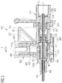
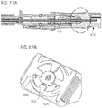
- the intravenous catheter assembly 410 generally comprises various features and elements to enable intravenous infusion of a fluid or medicament into a patient. In some instances, intravenous catheter assembly 410 further comprises features to enable removal of a fluid from a patient, such as blood.
- the intravenous catheter assembly 410 includes a catheter hub 412 having a first fluid path 411a and a second fluid path 411b, a catheter tube 414 and a needle 420 attached to a needle hub 416.
- the catheter hub 412 has a distal end 422 and a proximal end 424, wherein the catheter tube 414 is arranged adjacent to the distal end 422 of the catheter hub 412, for instance with a slip ring 461.
- the catheter tube 414 can generally include a biocompatible material that is made of a flexible or a semi-flexible polymer.
- the catheter tube 414 and the catheter assembly 410 may be integrally coupled such that an inner space defining a housing 448 of the catheter hub 412 extends into the catheter tube 414.
- the catheter hub 412 may also be provided with wings 462 which in use may be adhesively taped to the skin of the patient at the venipuncture site to maintain the catheter assembly/device 410 stationery during the infusion.
- the needle 420 has a needle shaft 428, a needle tip 454 at a distal section 463 of the needle shaft 428 and a needle hub 416 attached to a proximal section 436 of the needle shaft 428.
- An enlargement 496 of the needle 420 can be provided between the distal section 463 and the proximal section 436 of the needle shaft 428.
- the enlargement 496 can have a maximum dimension in a direction transverse to the needle shaft 428, which is greater than the outer diameter of the distal 463 or proximal section 436.
- the enlargement 496 can be made, for example, by crimping the needle shaft 428.
- the crimp may be made by a local depression 498 such that lateral protrusions/enlargement 496 result from the crimping process.
- the crimping process may be controlled such that the internal cross-sectional area of the needle 420 is not reduced substantially such that the through bore or the internal profile of the needle 420 is not affected.
- the needle 420 Prior to use of the catheter assembly 410, the needle 420 is received in the catheter hub 412 and catheter tube 414, such that the needle shaft 428 extends through the length of the catheter tube 414 and the needle tip 454 is exposed out of the catheter tip.
- the needle 420 is capable of piercing the skin to provide access to the vasculature or subcutaneous tissues of the patient. Once access is obtained, tip of catheter 414 is inserted through the newly formed opening and into the desired location within the patient. The needle 420 is then withdrawn from the catheter assembly 410, and catheter 414 is left disposed within the patient.
- the needle 420 may comprise at least one opening 497 covered by the tubular catheter 414.
- the opening 497 can provide communication between a lumen of the needle 420 and an interior of the tubular catheter 414. In the event of first venipuncture blood entering the lumen of the needle 420 can exit the needle 420 through the opening 497 and thus become visible for the person handling.
- the opening 497 is preferably large enough in order to provide an early blood flashback function within the tubular catheter 414 such that the practitioner can recognize that he has placed the needle 420 correctly within a patient's vein.
- the opening 497 is positioned close to the needle tip 454 so that the blood does not have to travel the length of the needle 420 to enter the needle hub 416 in order to become visible. Instead, blood entering the lumen of the needle 420 upon venipuncture partly exits the needle 420 near the needle tip 454, thereby becoming particularly quickly and, thus, allowing for particularly fast venipuncture confirmation.
- the opening 497 may have a miniscule size which serves the purpose of early flashback detection and which does not obstruct the arms of the needle guard 426.
- the opening 497 can be provided before or after the enlargement 496.
- the needle 420 may also be formed with the opening 497 arranged distally or proximally from the enlargement 496.
- the opening 497 may be formed by a small slit which is cut into the needle shaft 428 and which extends in axial direction A for about a small distance.
- the opening 497 may be just large enough in order to provide an early blood flashback function close to the needle tip 454 within the catheter tube 414 such that the practitioner can recognize that he has placed the needle 420 correctly within a patient's vein.
- blood pours out of the opening 497 within the needle shaft 428 into the space between the needle shaft 428 and the inner wall of the transparent catheter tube 414 and is visible to the practitioner.
- the catheter hub 412 is made of two parts, i.e. a first part 412a and a second part 412b.
- the first part 412a has a distal end section 450 and the second part 412b has a proximal end section 452.
- the distal end 422 of the second part 412b is connected to a catheter tube 414.
- the distal end section 450 of the first part 412a is configured to be assembled with the proximal end section 452 of the second part 412b in various ways in a fluid tight manner, such as by adhesive sealing, ultrasonic welding, heated die, radio frequency sealing, mechanical seal (snap fit), insert molding, laser welding etc., ensuring a leak free joint.
- first and second parts 412a and 412b are joined by complementary stepped end portions/surfaces 457, 459.
- a port 464 includes a port body having one or more integrated body portions which extend outwardly in a direction perpendicular to the axial direction A from the sidewall 470 of the catheter hub 412.
- the port 464 has an opening 465 defining an inlet and a bore 466 extending between the inlet and the opening 468 of the inner space 467 of the catheter hub 412.
- the port 464 and in particular, the inlet 465 and at least a portion of bore 466 is shaped and sized in conformity with the prescribed International Standards Organization (ISO) standards for a female luer connection. This will allow a male luer slip or male luer lock to be connected to port 464.
- the port 464 is covered with a port cap 469.
- the port 464 can be a side port or a top port. Fluids may be infused and withdrawn from the catheter assembly 410 through the port 464 in a sidewall 470 of the catheter hub.412.
- the sidewall 470 can be any wall of the catheter hub 412 that extends substantially axially along the catheter tube 414.
- the outer periphery and/or inner periphery of the port 464 body can include one or more luer threads or the like in any number of thread configurations available to provide and interlock between mating devices.
- the luer threads allow another medical device having a male luer lock to be connected to and interlocked with the port 464.
- the port 464 body can also have no luer threads to accommodate luer slip and luer lock connections.
- a first valve 471 may be provided in an inner space 467 adjacent to an inlet opening 468 in the catheter hub 412 to prevent foreign contamination from entering the catheter hub 412 that provides selective access through the port 464.
- the first valve 471 may include an elastomeric septum 472 having at least one slit that can form a fluid barrier until the septum deforms to allow fluid flow there through. Slit provides a fluid-tight seal, thereby preventing fluid from bypassing septum 472.
- the first valve 471 may generally comprise a flexible tube having an outer diameter that is approximately the same size as an inner diameter of the inner space 467 of the catheter hub 412, whereby the first valve 471 may be retained within the inner space 467 by an interference fit or by means of change of dimensions.
- the first valve 471 can be located on the inlet 465, within the inlet 465, adjacent to the inlet 465, within the bore 466 of the port body 464 or in the inner space 467 adjacent to the inlet opening 468 in the catheter hub 412. As shown in Fig. 4A , the first valve 471 is arranged within the bore 466 of the port body 464.
- First valve 471 may generally comprise a resilient, flexible material that is easily deformed when fluid is introduced to port 464 via a syringe or other compatible device. Materials such as silicone, silicone rubber, or polyisoprene or the like can be used to form the first valve 471.
- the first valve 471 can be formed as a single piece of elastomeric material that is formed to having various shapes and features.
- the first valve 471 can be a two-piece configuration having a flexible inner material, such as silicon or silicone rubber, and a more rigid outer portion, such as an outer ring.
- the outer ring can be formed of a plastic or metal or other suitable material.
- the first valve 471 includes at least one slit.
- first valve 471 can include a plurality of slits. In some configurations, at least a portion of the first valve 471 is glued to the port body 464 using one or more adhesives in a fluid tight manner. Additionally or alternatively, in some configurations, at least a portion of the first valve 471 is held in place between two or more portions of the port body 464 in a fluid tight manner.
- the port 464 can be accessed, with a male luer device that is inserted through the slit of the first valve 471.
- the male luer device can be interlocked with the luer threads if the male luer device includes a luer lock.
- a separate access device can be coupled to the catheter assembly 410 through the port 464 to establish fluid communication there through.
- a syringe, needle, or other such device can be inserted through the slit of the first valve 471 to withdraw fluids there through.
- medical personnel can access the inner space 467 of the catheter hub 412 without being exposed to the patient's blood.
- a blood control second valve 473 including a blood control septum 474 having at least one slit may be arranged within the inner space 467 of catheter hub 412 to prevent the outflow of fluid during and following removal of the needle 420.
- the second valve 473 can be configured with a plug 475 which is also housed in the inner space 467 of the catheter hub 412.
- the blood control second valve 473 can be elastomeric and be designed to closely conform to the shape of a needle 420 to prevent leaking.
- the blood control second valve 473 can also seal upon removal of the needle 420 due to axial compression forces on the second valve 473 that induces the second valve to close.
- the second valve 473 can have an outer diameter that is configured to compatibly seat within a groove or channel or other suitable projections formed on an inner surface 456 of the catheter hub 412.
- a valve receiving means such as a groove or channel or other suitable projections can be formed on the outer surface 458 of the second valve 473, which interlocks with one or more features on the inner surface 456 of the catheter hub 412.
- the second valve 473 is configured with a plug 475 which is also housed in the inner space 467 of the catheter hub 412.
- the plug 475 is in fluid communication with the second valve 473 and inner space 467 of the catheter hub 412.
- the inner surface 456 at a distal end 422 of the second valve 473 is provided with at least one projection or groove or vice versa matching with said at least one projection or groove provided in an outer wall/surface 458 of the plug 475 at a proximal end 424 thereof.
- the inner surface 456 at a distal end 422 of the second valve 473 can be provided with at least one projection matching with at least one groove provided in an outer wall/surface 458 of the plug 475 at a proximal end 424 thereof, or the inner surface 456 at a distal end 422 of the second valve 473 can be provided with at least one groove matching with at least one projection provided in an outer wall/surface 458 of the plug 475 at a proximal end 424 thereof.
- the plug 475 may be made from a first material, e.g.
- the second valve 473 may be made from a second material different from said first material for example, second material of the second valve 473 may be resilient, flexible material that is easily deformed when fluid is introduced to port via a syringe or other compatible device. Materials such as silicone, silicone rubber, or polyisoprene or the like can be used to form the second valve 473.
- the second valve 473 can be spaced from the first valve 471 being positioned within a fluid pathway through the inner space 467 of the hub 412 of the catheter assembly 410.
- the second valve 473 is tube or barrel shaped, while in other configurations, the second valve 473 is substantially cylindrical or disk shaped.
- the embodiments of the second valve 473 include other geometrical shapes and dimensions.
- the second valve 473 can be elastomeric and include one or more slits through which a septum activator can be inserted.
- the second valve 473 can include at least one slit.
- second valve 473 can include a plurality of slits. Slit can provide a fluid-tight seal, thereby preventing fluid from bypassing septum 474.
- proximal end 424 of the catheter hub 412 further comprises an opening 477 through which a separate secondary device may be inserted to infuse and withdraw fluid and/or liquid, such as a syringe or intravenous fluid line.
- proximal end 424 comprises a set of threads configured to threadedly receive the secondary device in a secure manner.
- Opening 477 may further comprise a tapered opening to receive secondary device via an interference or friction fit.
- Proximal end 424 and opening 477 may alternatively comprise various surfaces and other features to enable coupling to a needle hub 416, a diagnostic device, and other suitable infusion therapy equipment.
- valves 471, 473 may be secured within inner space 467 of the catheter hub 412 by any compatible means.
- valves 471, 473 are secured within inner space 467 via an adhesive.
- valves 471, 473 are secured within inner space 467 via an interference fit.
- valves 471, 473 are inserted into an annular groove formed on the inner surface of the catheter hub 412.
- the first valve 471 as shown in Fig 3 . is placed within inner space 467 so as to overlap and form a seal between inner space 467 and the pathway of the port 464.
- Both the first 471 and second 473 valves comprise a proximal opening, a distal opening, and a pathway extending therebetween.
- proximal opening comprises a reduced diameter.
- the embodiment shown in Fig. 3 is without a needle guard 426. However, a needle guard 426 can be housed within the housing of catheter hub 412 and/or needle hub 416.
- a needle guard 426 as shown in Fig 4B is movably arranged on the needle shaft 428 and retained in a needle guard casing 478.
- the needle guard casing 478 can be movably retained in the needle hub 416 prior to use of the catheter assembly 410 as shown in Fig. 4A , 4C & 4D .
- the needle hub 416 is provided with inner space 479 defining a housing to movably receive the needle guard casing 478 as shown in Figs 6A and 6B .
- the needle guard casing 478 has a substantially cylindrical shape, which is structurally beneficial to the provision of rotation capabilities.
- the needle guard casing 478 comprises an upper part 482 and a lower part 483 together forming a chamber 476 for housing the needle guard 426.
- the upper part 482 of the needle guard casing 478 is received on the lower part 483.
- the upper part 482 may be snap-fitted on the lower part 483.
- the snap-fit may be formed by a protrusion ring 484 and a corresponding groove ring 485 and which can be provided in both upper and lower part alternatively.
- the protrusion ring 484 may comprise the grooves and the groove ring 485 may comprise at least one projection or vice-versa.
- the ring of both the projections or groove can be a continuous ring or a spaced apart formation. Other ways and means for a secure engagement are also encompassed.
- Both the upper part 482 and lower part 483 of the needle guard casing 478 can be provided with a chamber 476 to safely house the needle guard 426.
- the chamber 476 is provided in the bottom portion 487 whereas in the lower part 483 the chamber 476 is provided in the top portion 486.
- Both the upper part 482 and lower part 483 has a bore 488 to receive the needle 420.
- the inner diameter of the bore 488 has a close fit ratio with the outer diameter of the needle 420.
- a distal end 422 of the upper part 482 can be provided with a fitment 489 which is received in the housing 448 of the catheter hub 412 creating a secure connection between the two.
- the fitment 489 also has a bore 488 which allows the needle 420 to pass there through.
- the inner diameter of the bore 488 has a close fit ratio with the outer diameter of the needle 420.
- an outer wall 458 of the catheter hub housing 448 is provided with at least one projection 480 or groove 481 or vice versa matching with said at least one projection 480 or groove 481 may be provided in an inner wall 456 adjoining said fitment 489.
- the needle guard casing 478 is safely secured with the catheter hub housing 448 by the means of change in dimensions.
- Alternative arrangements by way of replacing the change of dimensions within or outside the housing 448 and on the upper part 482 of the needle guard casing 478 can also be employed.
- the upper part 482 of the needle guard casing 478 can be made without the fitment 489 and be snap-fitted with the catheter hub housing 448.
- the snap-fit may be formed by a protrusion ring 484 and a corresponding groove ring 485.
- the protrusion ring 484 may comprise the groove and the groove ring 485 may comprise at least one projection or vice versa.
- the ring of both the projections or groove can be a continuous ring or a spaced apart formation.
- Other ways and means for a secure engagement are also encompassed, for example as shown in Figs. 4A , 4C & 4D .
- an inner wall 456 of the needle hub housing 479 can be provided with at least one projection 480 and/or groove 481 or vice versa matching with said at least one projection 480 and/or groove 481 is provided in an outer wall 458 of an upper 482 and/or lower 483 part of the needle guard casing 478.
- the needle guard casing 478 is safely secured within the needle hub housing 479 by the means of change in dimensions.
- Alternative arrangements by way of replacing the change of dimensions within the housing 479 and on the upper 482 and lower 483 part of the needle guard casing 478 can also be employed.
- the intravenous catheter assembly 410 of the invention can comprise a catheter hub 412 arranged at a proximal end 424 of a catheter tube 414 and defining a housing 448; a needle 420 defining an axial direction A and having a needle tip 454, wherein the needle 420 extends through the housing 448 and the catheter tube 414 when in a ready position; a needle guard 426 slidably arranged on the needle 420 and partly received in the housing 448 of the catheter hub 412 when the needle is in its ready position.
- the needle guard 426 is movably arranged on the needle shaft 428 and an upper end 490 of the needle guard 426 is securely retained in the housing 448 of the catheter hub 412 exposing the lower end 491 of the needle guard 426.
- the entire catheter hub 412 portion with the lower end 491 of the needle guard 426 is securely retained in an inner space 479 of the needle hub 416.
- the needle hub 416 is provided with inner space 479 defining a housing to movably receive the catheter hub 412 and the lower end 491 of the needle guard 426.
- the housing 479 of the needle hub 416 has a substantially cylindrical shape, which is structurally beneficial to the provision of rotation capabilities.
- an inner wall 456 of the needle hub 416 housing 479 is provided with at least one projection 480 and/or groove 481 or vice versa matching with said at least one projection 480 and/or groove 481 is provided in an outer wall 458 of the catheter hub 412.
- the catheter hub 412 is safely secured within the needle hub 416 housing 479 by the means of change in dimensions.
- Alternative arrangements by way of replacing the change of dimensions within the housing 479 and outer wall 458 of catheter hub 412 can also be employed.
- the catheter hub 412 can be snap-fitted in the housing 479 of the needle hub 416.
- the snap-fit may be formed by a protrusion ring 484 and a corresponding groove ring 485.
- the protrusion ring 484 may comprise at least one groove and the groove ring 485 may comprise at least one projection or vice versa.
- the ring of both the projections or groove can be a continuous ring or a spaced apart formation. Other ways and means for a secure engagement are also encompassed.
- the needle guard 426 can include a base portion 444 and first 440 and second 442 arms extending from the base portion 444, wherein the first arm 440 is deflected radially outwards by the needle 420 against a restoring force when the needle 420 is in its ready position whereby the needle guard 426 is brought into retaining contact with the catheter hub 412 by retaining means for retaining the needle guard 426 in the catheter housing 448 as long as the first arm 440 is in its deflected state.
- the base portion 444 has an axial through-bore 499 for receiving the needle 420.
- the inner diameter of the bore 499 has a close fit ratio with the outer diameter of the needle 420.
- the retaining means include a first disc-like retaining protrusion 493 provided on the first arm 440 and a retaining depression 494 formed in the inner surface 456 of the catheter hub 412 and adapted to receive the retaining protrusion 493.
- the disc-like retaining protrusion 493 has the benefit that in the ready position it is in engagement along a circular contact surface with the corresponding retaining depression 494 formed in the inner surface 456 of the catheter hub 412. This provides an engagement between the needle guard 426 and the catheter hub 412 along a substantial annular portion of the retaining protrusion 493 and the retaining depression 494 which provides a safe and reliable engagement between the two components as long as the needle guard 426 is in its ready position and is to be prevented from being retracted out of the needle hub 416. Even if the needle guard 426 is rotated within the catheter hub 412, this secure engagement between the catheter hub 412 and the needle guard 426 holds the needle guard 426 safely within the catheter hub 412.
- the catheter hub 412 can be manufactured more easily and, thus, at less manufacturing cost, in particular if the catheter hub 412 is a plastic part and e.g. formed by injection molding.
- the particular design of the first retaining protrusion 493 provided on the needle guard 426 ensures effective engagement of the retaining protrusion 493 with the retaining depression 494 and, thus, reliable retaining of the needle guard 426 in the catheter hub 412.
- the retaining protrusion 493 can be of part-circular, in particular semi-circular shape. More specifically, the retaining protrusion 493 may have generally parallel proximal and distal faces and/or a convex, in particular part-cylindrical, peripheral surface.
- the first retaining protrusion 493 can be arranged in the region of a distal end 422 of the first arm 440.
- a second disk-like retaining protrusion 495 is arranged on the second arm 442 and adapted to engage with the retaining depression 494 as long as the first arm 440 is in its deflected state.
- the second arm 442 can be deflected along its entire length radially inwards when the needle tip 454 is received between the arms 440, 442, to thereby allow the second retaining protrusion 495 to disengage from the retaining depression 494.
- the second retaining protrusion 495 can be arranged in the region of a distal end 422 of the second arm 442.
- the second retaining protrusion 495 may be arranged opposite from the first retaining protrusion 493.
- the retaining depression 494 is an at least part-annular depression, preferably an annular depression.
- the first arm 440 of the needle guard 426 can be longer than the second arm 442 and has a massive distal wall 418 having an undercut for catching the needle tip 454.
- the distal wall 418 is arranged at a distal end 422 of the first arm 440 and extends in a direction transverse to an axial direction A of the needle 420 such that the distal wall 418 completely blocks the needle 420.
- the distal wall 418 ensures that the needle tip 454 is prevented from axially projecting out or sideways projecting out of the needle guard 426.
- the distal wall 418 has a bigger dimension than the distal surface of the second arm 442 and much bigger dimension than the outer diameter of the needle 420 such that the distal wall 418 completely covers and blocks the needle tip 454 once confined and entrapped within the needle guard 426.
- the first and second arms 440, 442 of the needle guard 426 extend generally in the axial direction A from a distal side 460 of the base portion 444, i.e. generally parallel to the needle shaft 428.
- the first arm 440 deflects outward of the needle guard 426 such that the distal wall 418 of the first arm 440 is supported on the needle shaft 428. Further, in this ready position, the first and second arms 440, 442 do not engage or interact with an inner wall/surface 456 of the housing 448 prior and during venipuncture of a patient. This noncontact of the first and second arms 440, 442 with the inner surface 456 of the housing 448 significantly decreases the withdrawal force required and friction caused when a needle 420 is withdrawn through a catheter hub 412 being protected by a needle guard 426 after use.
- the needle shaft 428 moves relative to the needle guard 426 while the needle guard 426 is retained in the catheter hub 412 until the needle tip 454 is received in the needle guard 426.
- the enlargement 496 of the needle shaft 428 engages with the base portion 444 of the needle guard 426 via a stopping element 438 such that the needle guard 426 can be pulled out of the catheter hub 412 together with the needle 420.
- the needle 420 can comprise an engagement means provided at a distance from the needle tip 454 for engaging with the needle guard 426 and preventing the needle guard 426 from sliding off the needle 420.
- the engagement means is formed of by enlargement 496 of the radial dimension of the needle 420 in at least one direction as compared with a principal profile of the needle 420.
- the engagement means can be found by a local crimp, a shoulder, a bulge formed as an annular widening etc.
- the needle guard 426 can comprise a stopping element 438 engaging with the engagement means of the needle 420 when the needle tip 454 is received between the first 440 and second 442 arms.
- the stopping element 438 defines an axial bore having a cross-section adapted to the principal profile of the needle 420 but being smaller than the enlargement 496 of the needle 420.
- the stopping element 438 may be made of a material different from the material of the base portion 444, in particular of a metal material.
- the stopping element 438 may be of disc-like shape or tubular shape and/or arranged on a distal side 460 of the base portion 444. It can be fixed in the base portion 444 or supported in a floating manner on the needle 420.
- the catheter assembly 410 is particularly inexpensive to manufacture if the base portion 444, the first and second arms 440, 442 of the needle guard 426 are integrally made from a first material.
- the first material may, for example, be a plastic material.
- the base portion 444, the first and second arms 440, 442 could be manufactured by injection molding.
- the base portion 444, and one of the first and second arms 440, 442 can be integrally made from a first material, e.g. a plastic material, and the other one of the first and second arms 440, 442 can be made from a second material different from said first material.
- said other one of the first and second arms 440, 442 can include a strip of material having spring-like properties, e.g. a strip of sheet metal, providing the above-mentioned inherent elasticity.
- the restoring force is created by at least one of an elastic property of the first arm 440 and an additional tension element 446.
- the tension element446 for example, a rubber band or the like, surrounds the first and second arms 440, 442.
- the tension element 446 at least partly surrounding the arms 440, 442 in a region proximal of the first retaining protrusion 493 or - instead of surrounding the two arms 440, 442 - biasing the two arms 440, 442 by a linear biasing action.
- the first 440 and second 442 arms can be made of a resilient material having elastic properties.
- the construction and shape of the improved intravenous catheter assembly 410 according to the various embodiments of the present disclosure provides a simple configuration.
- the simple and compact design of the intravenous catheter assembly 410 according to the above disclosure is advantageous in a clinical setting because it smoothens the whole catheterization process thereby reducing injury or discomfort to a patient and provides better blood control features.
- such design greatly reduces manufacturing costs and is efficient, effective and simple in its construction and use.
- the catheter assembly may include a disc 500 arranged proximate to the first valve 471, the second valve 473, or both the first and the second valve.
- the disc 500 is arranged proximate to the first valve 471.
- the first valve 471 or the second valve 473 can be elastomeric and be designed to closely conform to the shape of a needle 420 to prevent leaking.
- the valve can have any geometrical shape and dimension.
- the valve can have a dumbbell form as shown in Fig. 8B .
- the valve can have a tube or barrel form as shown in Fig. 8C .
- the tube or barrel form can have the advantage that is easy and cheap to be manufactured. While reference is made to the first valve 471 in the above discussion, the disc 500 may also be arranged proximate to the first valve 473, wherein the same considerations regarding the shape and dimensions apply.
- the disc 500 may be arranged in direct contact or close to (i.e. spaced apart from) any of the valves 471, 473.
- the disc 500 may be arranged proximal or distal to the valve.
- the disc 500 may have circular or part-circular profile, a profile of a C-shape as shown in Fig. 8D , a ring-shape (or closed circle, full round shape) as shown in Fig. 8E . or any other shape such as a half-circle (not shown).
- the disc 500 can be configured to hold the valve in its position, for instance due to interaction of the disc 500 with alignment features in the inner wall of the catheter hub.
- the alignment features may be a recess or groove formed in the interior surface of the catheter hub, while the disc 500 comprises a corresponding projection or protrusion configured to engage the recess or groove, as may be seen in Fig. 8A .
- the disc 500 can be configured such that at a high pressure, the valve arranged proximate to the disc 500 does not displace from its position.
- the proximal end of the catheter hub may include at least one cut 501.
- the catheter hub 412 may include two cuts 501 on opposite sides of the proximal end of the catheter hub.
- the at least one cut 501 may be formed by cutting a slit into the proximal end of the catheter hub or by molding the catheter hub to include the cut or slit at a proximal end of the catheter hub.
- the cut 501 may have a rectangular shape as shown in Fig. 9A or any other shape, such as a slit shape or V shape.
- the cut 501 may support locking of the catheter hub 412 with the needle hub 416.
- the cut 501 may further restrict the rotation of the catheter hub 412 with respect to the needle hub 416, for instance be interacting with corresponding protrusion on the needle hub 416.
- the cut 501 may also be configured to reduce the withdrawal force required to withdraw the needle hub 416 from the catheter hub 412. The reduction of the withdrawal force may be provided, as the flexibility of the proximal end 424 of the catheter hub is increased by the cut 501.
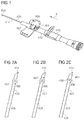
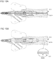
- the needle 420 may comprise a proximal needle feature 502 at the proximal end, opposite to the needle tip end.
- the proximal needle feature 502 may be a needle bend 502A as shown in Fig. 10A , a needle crimp 502B as shown in Fig. 10B or a needle pressing 502C as shown in Fig. 10C .
- the needle may comprise only a slight needle bend or a complete needle bend.
- the needle may be crimped at the proximal end with any known method known to the skilled person.
- the needle may be pressed at its proximal end.
- the proximal needle feature 502 may be located at a proximal end of the needle hub 416 as shown in Figs. 10A, 10B and 10C .
- the proximal needle feature 502 may be attached to the proximal end of the needle hub 416 by a needle fixation means 503 such as glue.
- the needle fixation means 503 such as the glue may also seal the proximal needle end.
- the proximal needle feature 502 can, in addition to the needle fixation means 503, increase the force required to separate the needle 420 from the needle hub 416.
- the needle is assembled with the needle hub and then crimped, bend or pressed.
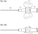
- the catheter hub 412 may be provided with wings 462 which in use may be adhesively taped to the skin of the patient at the venipuncture site to maintain the catheter assembly/device 410 stationery during the infusion. While the wings 462 may be integrally formed with the catheter hub, as shown in Fig. 1 , the following describes separate wings 462 that may be affixed to the catheter hub.
- the catheter hub 412 may include at least one wing alignment feature 505 that is configured to interact with at least one catheter hub alignment feature 506 on the wings 462.
- the wing alignment feature 505 can be configured to restrict or prevent wing rotation.
- the wing alignment feature 505 can comprise at least one wing alignment projection 505A extending from the outer surface of the catheter hub 412.
- the wing alignment feature 505 may comprise at least one wing alignment projection 505A.
- the wing alignment feature 505 comprises two wing alignment projections 505A extending in opposite radial direction from the outer surface of the catheter hub 412 as can be seen in Fig.
- the at least one wing alignment projection 505A may be arranged in the same plane as the wing members 510, i.e. the wing members 510 extend in a first plane, e.g. a horizontal plane, and the wing alignment projection or projections 505A extend in the same plane.
- the at least one wing alignment projection 505A may be configured to prevent distal movement of the wings 462 as well as to prevent wing rotation.
- the wing alignment projection 505A may be in the form of a rib, a nose-like or a ramp-like shape, with its radial dimension increasing in proximal direction.
- a proximal face of the wing alignment projection 505A can extend in a plane generally perpendicular to the axial direction, i.e. in a radial plane.
- the proximal face of the wing alignment projection 505A can be configured to interact with a corresponding element of the wings 462 to prevent distal movement of the wings 462 beyond the wing alignment projection 505A.
- Side faces of the wing alignment projection 505A extend in a plane generally parallel to the axial direction. At least one of the side faces of the wing alignment projection 505A can be configured to interact with a corresponding element of the wings 462 to prevent rotational movement of the wings 462 beyond the wing alignment projection 505A.
- the wing alignment projection 505A may be integrally formed with the catheter hub 412.
- the wing alignment feature 505 may further comprise a wing alignment element 505B.
- the wing alignment element 505B may include at least one annular projection 505C extending outwardly from the outer surface of the catheter hub 412.
- the wing alignment element 505B may include two annular projections 505C spaced apart from each other in axial direction A, thereby forming a annular recess 505D between the two annular projections.
- the annular recess 505D may have the same outer diameter as the outer diameter of the catheter hub, while the two annular projections 505C have a greater diameter than the outer diameter of the catheter hub.
- the wing alignment element 505B may further include at least one lateral projection 505E formed on the annular recess 505D and connecting the two annular projections 505C in axial direction A.
- the wing alignment element 505B, including the annular projections 505C, the annular recess 505D and the lateral projection 505E may be integrally formed with the catheter hub 412.
- the wing alignment element 505B may only comprise one annular projection 505C provided such that an annular recess 505D, which may have the dimension of the catheter hub, is arranged distal to the annular projection 505C.
- This wing alignment element 505B may still comprise a lateral projection 505E extending distally from annular projection 505C.
- the wing alignment feature 505 may also have no annular projections, but only include an annular recess 505D having a smaller diameter than the outer diameter of the catheter hub.
- the lateral projection 505E has the same diameter as the outer diameter of the catheter hub.
- any of the above described wing alignment elements 505B can be configured to guide and orient the wings 462 during assembly of the wings with the catheter hub 412.
- the wing alignment element 505B may further be configured to prevent wing rotation.
- the at least one wing alignment projection 505A may be provided on any of the annular projections 505C, preferably on the distal annular projection 505C.
- the wings 462 may comprise a catheter hub alignment feature 506 configured to align and orient with the catheter hub 412.
- the catheter hub alignment feature 506 may comprise a wing base 506A.
- the wing base 506A may have a tubular or ring-like body, at a bottom part of which the two wing members 510 extend from.
- the wing members 510 can either be formed integrally with the wing base 506A, or they can be separate elements that are attached to the wing base.
- the wing base 506A can be configured to receive the proximal end of the catheter hub.
- the wing base 506A can further be dimensioned to allow passage of the catheter hub, but to interact with or block the wing alignment projection 505A to prevent distal movement of the wings 462 beyond the wing alignment projection 505A.
- the catheter hub alignment feature 506 may further comprise a wing socket 506B.
- the wing socket 506B may have a semi-circular or half-ring shape and may be provided distal to the wing alignment projection 505A.
- the wing socket 506B can be configured to interact with the wing alignment projection 505A to prevent wing rotation.
- the wing socket 506B can comprise a top surface that interacts with a side face of the wing alignment projection 505A.
- the side face of the wing alignment projection 505A can be configured to interact with the top surface of the wing socket 506B to prevent rotational movement of the wings 462 beyond the wing alignment projection 505A.
- the wing socket 506B can be integrally molded with the wing base 506A, i.e. the wing socket 506B can extend in distal direction from wing base 506A.
- a slot 506C may be provided between the wing base 506A and the wing socket 506B.
- the slot 506C can be configured to receive one of the annular projections 505C of the catheter hub.
- the wing base 506A may comprise an indent 506D, for example in the form of a groove or other recess configured to receive the lateral projection 505E.
- the wing alignment feature 505 may further comprise at least one stopper element 507.
- the stopper element 507 can have generally nose-like or ramp-like shape, with its radial dimension increasing in distal direction. A distal face of the stopper element 507 extends in a plane generally perpendicular to the axial direction, i.e. in a radial plane.
- the stopper element 507 may be provided on the proximal annular projection 505C. At least two stopper elements may be provided on opposite sides of the catheter hub.
- the stopper element 507 may be made of a resilient material.
- the stopper element 507 may be configured to deflect to let the wing base 506A pass in distal direction.
- the stopper element 507 may further be configured to take its original undeflected state after the wing base 506A has passed, thereby locking the wings 462 between the stopper element 507 and the wing alignment projection 505A, as shown in Fig. 11C .
- the stopper element 507 can be resiliently deformed to allow.
- the position of the stopper element 507 can be on the same plane as the wing members 510 and the wing alignment projection 505A of the wings 462.
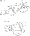
- the catheter assembly comprises a catheter hub 412 with a wing alignment feature 505 and wings 462 with a catheter hub alignment feature 506, wherein the wing alignment feature 505 and the catheter hub alignment feature 506 are configured to align and orient the catheter hub and the wings with each other.
- the wing alignment feature 505 of the catheter hub comprises two wing alignment projections 505A such as two ribs extending in opposite radial direction from the outer surface of the catheter hub 412.
- the wings 462 comprise a tubular shaped wing base 506A, the distal side of which interacts with the wing alignment projections 505A to prevent distal movement of the wings beyond the catheter hub alignment feature 506.
- the wing alignment projections 505A further comprise a wing alignment element 505B comprising two annular projections 505C spaced apart and forming an annular recess 505D therebetween, wherein two lateral projections 505E connect the two annular projections 505C in axial direction A.
- the two wing alignment projections 505A are arranged on the distal one of the annular projections 505C and extend outwardly therefrom.
- two stopper elements 507 are provided on the proximal one of the two annular projections 505C.
- the two wing alignment projections 505A, the two lateral projections 505E and the two stopper elements 507 are each provided on the same plane as the plane of the wing members 510 and on opposite sides of the catheter hub 412.
- the wings 462 comprise a wing base 506A with two indents 506D aligned with and configured to receive the lateral projections 505E.
- the wings 462 further comprise a wing socket 506B with a slot having a dimension configured to receive the distal one of the annular projections 505C.
- the interaction of the wing alignment feature 505 and the catheter alignment feature 506 provides that the wings 462 are properly aligned and oriented with the catheter hub 412 and can be safely and easily assembled. Further, the interaction of the wing alignment feature 505 and the catheter hub alignment feature 506 provides that the wings 462 cannot move into distal or proximal direction and cannot rotate with respect to the catheter hub 412 after assembly.
- the needle hub 416 may comprise at least one needle guard engaging element 508 configured to restrict the rotation of the needle guard 426.
- the at least one needle guard engaging element 508 may be a rib extending from the inner wall of the needle hub 416 or extending from the needle guard casing 478 towards the center.
- the at least one needle guard engaging element 508 may be arranged at a base of the needle hub 416 or needle guard casing 478.
- the at least one needle guard engaging element 508 may be positioned at the lower part 483 of the needle guard casing 478.
- the needle guard may comprise a corresponding needle guard anti-rotation element 509 configured to engage the needle guard engaging element 508,
- the wings 462 may comprise two wing members 510.
- Each wing member may be made of a soft material, which may be selected from thermoplastic elastomers (TPE), polyvinylchloride (PVC), isoprene, rubber, ethylenevinylacetate (EVA), and other elastomeric or resilient materials.
- TPE thermoplastic elastomers
- PVC polyvinylchloride
- EVA ethylenevinylacetate
- Each wing member may be made of a rigid material, for instance comprising polypropylene (PP).
- PP polypropylene
- Each wing member may also be made of a combination of a soft and a rigid material selected from the above materials.
- Each wing member may comprise at least one through-hole as shown in Figs. 13A and 13B .
- the wings 462 may further comprise a window 511 configured for air venting.
- the window 511 may be provided in the bottom part of the wing base 506A connecting the two wing members
- the wings 462 may have a tapered profile.
- the tapered profile may have an increasing width in proximal direction.
- the taper may also have a nose-like or a ramp-like shape, with its radial dimension increasing in proximal direction.
- the tapered profile can support the alignment of the device with a patient's body and can support the insertion of the needle.
- the proximal end 424 of the catheter hub 412 may be curved and/or tapered.
- the curved and/or tapered proximal end 424 may simplify assembly of the catheter hub 412 with the needle hub 416.
- the catheter assembly can comprise a port 464.
- the port 464 has an opening 465 defining an inlet and a bore 466 extending between the inlet and the opening 468 of the inner space 467 of the catheter hub 412.
- the port 464 is covered with a port cap 469.
- the port may include a port hole 512,
- the port hole 512 may be provided in the port 464.
- the port hole 512 can contribute in directional flow of fluid through the port 464.
- the port hole profile and location can be changed and the specific position and design of the port hole 512 can be configured to optimize the flow and pressure balance.
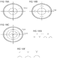
- Figs. 17A, 17B, 17C, 17D, 17E, and 17F show different configurations of a valve.
- the valve may be the first valve 471 or the second valve 473.
- Corresponding valves are described in further detail in WO 2014/153302 , which are incorporated herein by reference.
- the valve described in connection with any of the embodiments herein may comprise an elastomeric member 513 having a peripheral wall 514 projecting from a base surface 515.
- the base surface 515 can comprise at least one slit 516, which passes through the thickness of the base surface 515.
- the elastomeric member 513 can have a lateral annular protrusion 517 from edge of the base surface 515 configured to be received by a recess (not shown) within an interior wall of the catheter hub.
- the lateral annular protrusion 517 can support the holding of the valve in the catheter hub.
- the lateral annular protrusion 517 may not be required, for instance in cases in which a disc 500 is provided, as described in further detail above.
- the elastomeric member 513 can include a vertical annular projection 518 from the base surface 515 for providing interference with the catheter hub.
- the base surface 515 can include an inner vertical projection 519 extending from the base surface 515 in the direction of the peripheral wall 514.
- the inner vertical projection 519 may have a rounded shape, as shown in Figs. 17A and 17B .
- the base surface 515 can include a second vertical projection 520 extending from the vertical annular projection 518.
- the second vertical projection 520 may have a smaller diameter than the vertical annular projection 518, as shown in Figs. 17C and 17D.
- Figs. 17E and 17F show a further configuration of the second vertical projection 520 with a larger diameter.
- the valve can comprise at least one slit 516 in the base surface 515.
- the slits described herein may also be provided any other valve configurations, e.g. in tubular or dumbbell shaped valves, without the other features described for the valves in Figs. 17A to 17F .
- the valve can comprise at least one center slit 516A,
- the center slit 516A may have a Y shape, as shown in Fig. 18A .
- a center slit 516A can support the introduction of the needle in the valve and can be configured to seal once the needle is withdrawn. In one embodiment, there may be no flow through the center slit 516A.
- the valve can comprise at least one outer slit 516B.
- the at least one outer slit 516B can form an outer slit profile, for example made up by four slits at the same distance from the center of the valve, which may be have an arc shape, as shown in Fig. 18B .
- An outer slit 516B can contribute towards aspiratory flow, for instance while drawing blood using a syringe.
- the valve can comprise at least one center slit 516A and at least one outer slit 516B.
- the valve can comprise one center Y shaped slit and four V shaped slits at a same distance from the center slit, as shown in Fig. 18C .
- the center slit 516A can have the form of a hole, a slit, a cross slit, a plus slit, a Y slit, an arc slit, a V slit, or any other shape.
- the center slit profile may vary with respect to the shape, size, or orientation of the slit.
- the center slit may be made in any way or process.
- the outer slit may have the form of a slit, a T slit, a Y slit, a V slit, a rounded V slit, an arc slit, or any other shape.
- the outer slit profile may vary with respect to the shape, size, orientation, location or number of the at least one slit.
- the at least one outer slit may be made in any way or process.
- the valve may comprise any combination of a central slit and outer slits described above.
- the disc 500 already discussed further above may be joint or linked at a joint 500A to the valve.
- the disc 500 may extend from the base surface in the direction of the peripheral wall 514 as shown in Fig. 19A , or may extend from the base surface in the opposite direction of the peripheral wall 514, to the outside of the valve, as shown in Fig. 19B .
- the disc may be joint to any kind of valve, having a different configuration than shown in Figs. 19A and 19B .
- the disc 500 may be joint to a valve having a dumbbell shape or a tubular shape, as discussed above.
- the disc 500 may be made of rigid, a semi-rigid or a soft material.
- the thickness, the shape and the size of the disc 500 may vary to optimize the function of the disc in stabilizing the valve and holding the valve in its position.
- the joint may be made by glue, welding, insert moulding or other means known to the skilled person.
Description
- The invention generally relates to intravenous catheter assemblies. More particularly, the invention relates to an intravenous catheter assembly comprising a catheter hub arranged at a proximal end of a catheter tube and having an inner space defining a housing; a needle having a needle tip attached to a needle hub having inner space defining a housing and extending through both the housings and the catheter tube when in a ready position.
- An intravenous catheter assembly of this kind is generally known. Catheter assemblies are used to place a catheter properly into the vascular system of a patient. Once in place, catheters such as intravenous ("IV") catheters may be used to infuse fluids including normal saline, medicinal compounds, and/or nutritional compositions or the like into a patient in need of such treatment. Catheters additionally enable the removal of fluids from the circulatory system and monitoring of conditions within the vascular system of the patient.
- One type of commonly used catheter is a peripheral intravenous catheter which are indwelling intravenous catheters often used to provide an entry route for medications, fluid for hydration, and in some cases, for parenteral feeding, into a patient. Such catheters are generally short in length, ranging from about one-half to about three inches in length, and are generally made of flexible biocompatible materials. Peripheral intravenous catheters are often provided as "over-the-needle" catheters mounted over an introducer needle with a sharp distal tip. A portion of the catheter including at least the distal tip of the catheter securely grips the outside of the needle to prevent catheter peelback during insertion of the catheter into the circulatory system of the patient. Although several techniques for placing such catheters are practiced in the art, many generally include the step of inserting at least a portion of the needle into the target vessel and then sliding the catheter over the needle into place.
- Once placement of the needle has been confirmed, the medical personnel may remove the needle, leaving the catheter in place. A septum within the catheter housing can prevent the outflow of fluid during and following removal of the introducer needle. These septum structures are generally elastomeric and are designed to closely conform to the shape of a needle during storage and use to prevent leaking, then to seal upon removal of the needle. However, if the needle is left within the septum for long periods, the septum may not completely seal after the needle is removed, having conformed, in part, to the shape of the withdrawn needle. An incompletely sealed septum can increase the risk of blood exposure to medical personnel, since blood may flow through the small opening in the slit of the septum. It would thus be an improvement in the art to provide a catheter assembly with more reliable sealing functionality. Such a catheter assembly is disclosed herein.
-
WO 2016/142410 A1 discloses a catheter assembly with a valve and a securing ring that is coupled to the valve.GB 2 508 466 A US 2013/090609 A1 discloses a catheter assembly with a barrier member comprising one or more slits therethrough. - A primary object and advantage of the present invention is to provide an improved intravenous catheter assembly which is inexpensive to manufacture, efficient, effective and simple in its construction and use.
- It is another object of the present invention to provide an intravenous catheter assembly which has better blood control features.
- It is another object of the present invention to provide a compact design for housing one or more valves within the catheter hub housing of the intravenous catheter assembly having better blood control features.
- One example useful for understanding the present invention relates to an intravenous catheter assembly comprising: a catheter tube; a catheter hub having a distal section and a proximal section, wherein the distal section is joined to the catheter tube and the proximal section defines a housing; a port provided on the catheter hub forming an opening into the inner space covered by a port cap, a needle extending through the catheter hub and the catheter tube and defining an axial direction, wherein the needle has opposite proximal and distal ends, the distal end forming a needle tip; a needle hub attached to the proximal end of the needle. The hub is also provided with wings which in use may be adhesively taped to the skin of the patient at the venipuncture site to maintain the device stationery during the infusion.
- The port in the catheter assembly forms an opening into the inner space which can be covered by a port cap. In one of the embodiments, a first valve is provided adjacent to the port opening that provides selective access through the port. Fluid may be infused and withdrawn from the catheter through the port without the problem of leakage/outflow or risk of blood exposure. Thus, the port forms a first fluid path from the external environment into the inner space of the catheter assembly. The first valve provided in the first flow path further provides the ability to infuse and withdraw liquids through the port. Thus, the valve on or in the port provides a number of benefits when used with blood control-type catheter assemblies.
- The catheter assembly is also provided with a second valve in the inner space which selectively seals a proximal end of the inner space of the catheter housing. Placing the second valve in the catheter hub avoids the problems of outflow of fluid for example, when the second valve is in the path of an introducer needle in the inner space of the catheter hub. The second valve is configured with a plug which is also housed in the inner space of the catheter hub.
- Accordingly, in some implementations of the invention, the first valve adjacent to the port opening is utilized with a catheter assembly having an internal blood control second valve (also named second valve). The second valve can include a blood control septum. The blood control septum is provided to allow selective flow of fluid through the fluid pathway. For example, the blood control septum may include a slit that may be bypassed when an external luer device is coupled to the hub of the catheter assembly and directly engaging the septum. Upon removing the external luer device, the slit is closed to prevent blood from leaking out of the catheter assembly.
- A septum activator may also be located within the inner space at a location that is behind the second valve. When a separate luer device is inserted into the proximal end of the catheter hub, the septum activator is advanced forward through the blood control septum of the second valve, activating the blood control septum. The septum activator generally comprises a tubular body that is rigid or semi-rigid. The tubular body further comprises an inner lumen for facilitating flow of a fluid and/or liquid through the septum activator. The distal end of the tubular body can be shaped and sized to compatibly enter within the one or more slits of the blood control septum of the second valve.
- The valves provided can be of various types which can be incorporated into the port and the inner space in the catheter housing to provide medical personnel with the ability to infuse and withdraw fluids from the catheter assembly. The valve can be a one-way valve or a two-way valve. A two-way valve is a valve that permits fluid flow in two directions through or around the valve when the valve is open. Non-limiting examples of a two-way valve include a split septum, a ball valve, and an iris valve or the like. Thus, a two-way valve can permit fluid to be introduced into the catheter assembly (a first way) and to be withdrawn from the catheter assembly (a second way).
- In some embodiments, the valve is a one-way valve, which is a valve that only permits substantial fluid flow in a single direction when the valve is open. A non-limiting example of a one-way valve is a check valve.
- The valve can be housed inside the port or in the inner space provided in the housing of the catheter assembly. These valve types are not presented as an exhaustive set of valve types, and thus it will be understood that other suitable valves can be utilized in port and the catheter assembly.
- In further embodiments of the invention, the first valve can be located on a removable luer access connector that can be connected and disconnected from the port. Alternatively, the first valve can be located on a luer access connector that is fixedly connected to the port. The first valve can be a luer access valve that accommodates the insertion of a luer device, such as those commonly used in the medical industry. Moreover, a body portion of the port can include luer threads or other connecting and/or fastening features that can secure a luer device to the catheter assembly.
- In some configurations, the port can be disposed at an angle relative to the longitudinal axis of the catheter in order to modify the direction at which fluids are infused into the inner housing of the catheter assembly. This angle can be between about 10° to about 90°.The angle of the port can be modified to facilitate use, optimize performance, and/or optimize fluid flow within the inner space of the catheter assembly.
- The embodiments of the present invention may also include the provisions for including a needle guard slidably arranged on the needle, wherein the needle guard is movably retained in the housing of the catheter hub when the needle extends through the catheter hub and the catheter tube, and wherein the needle guard is removable from the catheter hub once the needle tip is received in the needle guard upon withdrawal of the needle from the catheter tube; and wherein the housing defines a chamber at one end thereof ensuring that a first and second arms of the needle guard do not engage or interact with an inner surface of the chamber prior and during venipuncture of a patient. An intravenous catheter assembly of this kind is generally known. The needle guard serves to prevent a person handling the intravenous catheter apparatus from accidentally coming into contact with the needle tip after placement of the catheter tube in and subsequent removal of the needle from a patient's vein. Thereby, the intravenous catheter assembly helps to avoid unwanted transmission of blood borne diseases.
- As well known in the art, the needle may also have a needle feature close to its needle tip, which interacts with a proportional base of the needle guard, e.g. a curving or a bulge or crimp any other change in profile. Thereby, it can be prevented that the needle is retracted out of the needle guard, which is known in the art.
- In an embodiment, the catheter hub is made of two parts. The first and second parts being joined together define the housing having an inner space. The first and second part may form the housing, in particular, the distal end section of the first part and the proximal end section of the second part may form the housing, which ensures that no undercut has to be formed in either one of the first and second part.
- Further, the first part includes the port defining a first flow path. Alternatively, it is also possible to provide the port on the second part. The first and second parts of the catheter hub may be joined by complementary end portions, which preferably as such extend at an angle with regard to the axial direction. This ensures that both parts are aligned concentrically towards each other. Thereby, the assembly of such a catheter hub can be made easier. These end portions may be stepped, which enlarges their contact area for a better mutual interconnection.
- In an embodiment, the inner space of the catheter hub may receive a needle guard which is movably arranged on the needle shaft. The chamber may be formed by an indentation in the housing for accommodating the first and second arm such that none of the arms deflected by the needle contacts an inner surface of the chamber. Through such indentation the overall outer dimensions of the housing and the catheter hub can be kept small, which it is still provided that the first arm and second arm of the needle guard do not contact the inner wall surface of the chamber.
- The inner space of the housing may be parallel to the axial direction and defined by the distal end section of the first part and the proximal end section of the second part of the catheter hub. Alternatively, the inner space of the housing is defined only by one of the first or second part i.e. by either the distal end section of the first part or the proximal end section of the second part. Further alternatively, the inner space of the housing is defined by the proximal end section of the second part. The advantage in this lies in the fact that only one of the two parts forming the catheter hub has to be dimensioned very precisely in order to ensure an inner space with a well-controlled and large enough diameter such that none of the arms of the needle guard when housed in the inner space of the catheter hub contact said inner surface. In this regard, it is advantageous that the inner space of the housing is defined by the first and second part comprising the second fluid path.
- According to one of the embodiments of the invention, one of the first or second part of the catheter hub comprises a surface joined with the inner surface of the one of the first or second part, which surface is inclined towards the inside of the housing in a proximal direction of the catheter hub, wherein the surface has a smaller inside diameter at its innermost end than a distance between outermost points of the arms in their deflected state inside the chamber. Preferably, the first part comprises the surface joined with the inner surface of the second part. Preferably, the distal end section of the first part comprises the surface joined with the inner surface of the proximal end section of the second part. Such a surface serves as a stop for the arms of the needle guard when housed in the inner space of the catheter hub in their deflected state such that they cannot be pulled out of the catheter hub in the proximal axial direction as long as the needle deflects them outward in the ready position of the needle guard. On the other hand, the inclination of the surface supports that the arms are directed inwards when the needle guard is pulled out in the retracted position, even if they have been plastically deformed by the needle in their deflected state.
- In some embodiments, an antimicrobial coating is applied to one or more surfaces of the intravenous catheter assembly. The antimicrobial coating further includes an antimicrobial agent that is compatible for use in intravenous catheter assembly used for infusion therapy. Non-limiting examples of suitable antimicrobial agents include chlorhexidine diacetate, chlorhexidine gluconate, alexidine, silver sulfadiazine, silver acetate, silver citrate hydrate, cetrimide, cetyl pyridium chloride, benzalkonium chloride, o-phthalaldehyde, and silver element.
- Accordingly, one of the embodiments of the present invention relates to an intravenous catheter assembly with the features of claim 1, comprising: a catheter tube; a catheter hub having a distal end and a proximal end, wherein the distal end is joined to the catheter tube and the proximal end defines a housing having inner space; a needle extending through the catheter hub and the catheter tube and defining an axial direction (A), wherein the needle has opposite proximal and distal ends, the distal end forming a needle tip; a port extending outwardly in a direction perpendicular to the axial direction (A) from a sidewall of the catheter hub; a needle hub attached to the proximal end of the needle; a first valve provided in the inner space in the catheter hub to prevent foreign contamination from entering the catheter hub; a blood control second valve arranged within the inner space of catheter hub to prevent the outflow of fluid during and following removal of the needle wherein the second valve configured with a plug also housed in the inner space of the catheter hub.
- One example useful for understanding the present invention relates to an intravenous catheter assembly comprising: a catheter tube; a catheter hub having a distal end and a proximal end, wherein the distal end is joined to the catheter tube and the proximal end defines a housing having inner space; a needle extending through the catheter hub and the catheter tube and defining an axial direction (A), wherein the needle has opposite proximal and distal ends, the distal end forming a needle tip; a port extending outwardly in a direction perpendicular to the axial direction (A) from a sidewall of the catheter hub a needle hub attached to the proximal end of the needle having a housing; a needle guard slidably arranged on the needle, wherein the needle guard is movably retained in a needle guard casing and the needle guard casing is movably retained in the housing of the needle hub, when the needle extends through the needle hub, catheter hub and the catheter tube, wherein the needle guard is removable from the needle hub being retained in the needle guard casing once the needle tip is received in the needle guard upon withdrawal of the needle from the catheter tube.
- One example useful for understanding the present invention relates to an intravenous catheter assembly comprising: a catheter tube; a catheter hub having a distal end and a proximal end, wherein the distal end is joined to the catheter tube and the proximal end defines a housing having inner space; a needle extending through the catheter hub and the catheter tube and defining an axial direction (A), wherein the needle has opposite proximal and distal ends, the distal end forming a needle tip; a port extending outwardly in a direction perpendicular to the axial direction (A) from a sidewall of the catheter hub; a needle hub attached to the proximal end of the needle having a housing; a needle guard slidably arranged on the needle and an upper end of the needle guard is securely retained in the housing of the catheter hub exposing the lower end of the needle guard and wherein in the ready to use position, the entire catheter hub portion with the lower end of the needle guard is securely retained in an inner space of the needle hub.
- Some examples of the present invention further comprise one or more methods for manufacturing an intravenous catheter assembly according to the teachings of the instant invention. For example, in at least one embodiment a method of manufacturing is provided comprising the following steps: 1) providing catheter assembly having a catheter hub which has a proximal end, a distal end and an inner space extending therebetween, ; 2) placing a side port on a sidewall of the catheter hub and forming a pathway through the sidewall of the catheter hub and in communication with the inner space: 3) disposing a first valve within the inner space and forming a seal between the inner space and the pathway of the side port 4) disposing a blood control second valve within the inner space and dividing the inner space into a proximal chamber and a distal chamber. In some instances, a further step is provided for providing a needle guard for securely covering the needle tip once withdrawn from the patient in order to prevent accidental pricking. The needle guard can be housed in the catheter hub or the needle hub or in part within the catheter hub or in part within the needle hub or in part both within the catheter hub or needle hub or within a needle guard casing. Alternatively, a needle guard can be located outside of a catheter hub, such as in a separate hub different from the catheter hub and needle hub. The needle guard of the present disclosure may embody any number or type of prior art guards configured for blocking or covering the needle tip of the needle in protected position.
- Some examples of the present invention further comprise a disc arranged proximate to the first valve, the second valve, or both the first and the second valve.
The disc can be configured to hold the valve in its position. The disc can be configured such that at a high pressure, the valve arranged proximate to the disc does not displace from its position. - Some embodiments of the present invention further comprise a cut in the proximal end of the catheter hub. The cut may support locking of the catheter hub with the needle hub. The cut may further restrict the rotation of the catheter hub with respect to the needle hub. The cut may also be configured to reduce the withdrawal force required to withdraw the needle hub from the catheter hub.
- Some embodiments of the present invention further comprise a proximal needle feature at the proximal end, opposite to the needle tip end. The proximal needle feature can, in addition to needle fixation means, increase the force required to separate the needle from the needle hub.
- Some examples of the present invention further comprise at least one wing alignment feature and/or at least one catheter alignment feature configured to align and orient the wing with the catheter hub. The at least one wing alignment feature and/or at least one catheter alignment feature can further be configured to prevent distal or proximal movement of the wings with respect to the catheter hub.
- Some embodiments of the present invention further comprise at least one needle guard engaging element configured to restrict the rotation of the needle guard. The needle guard may comprise a corresponding needle guard anti-rotation element configured to engage the needle guard engaging element,
Some embodiments of the present invention further comprise wing members made of a soft material, a rigid material, or a combination of a soft and a rigid material. The wings may further comprise a window configured for air venting. - Some embodiments of the present invention further comprise wings having a tapered profile. The tapered profile may have an increasing width in proximal direction. The tapered profile can support the alignment of the device with a patient's body and can support the insertion of the needle.
- Some embodiments of the present invention further comprise a curved and/or tapered proximal end of the catheter hub. The curved and/or tapered proximal end may simplify assembly of the catheter hub with the needle hub.
- Some embodiments of the present invention further comprise a port including a port hole, the port hole can contribute in directional flow of fluid through the port. The port hole profile and location can be changed and the specific position and design of the port hole can be configured to optimize the flow and pressure balance.
- Some embodiments of the present invention may comprise a valve comprising an elastomeric member having a peripheral wall projecting from a base surface. The base surface can comprise at least one slit, which passes through the thickness of the base surface. The elastomeric member can have a lateral annular protrusion from edge of the base surface configured to be received by a recess (not shown) within an interior wall of the catheter hub. The lateral annular protrusion can support the holding of the valve in the catheter hub.
- Some embodiments of the present invention may comprise an inner vertical projection extending from the base surface of the valve. The inner vertical projection may have a rounded shape. The base surface can include a second vertical projection extending from the vertical annular projection. The second vertical projection may have a smaller diameter than the vertical annular projection.
- Some embodiments of the present invention may comprise a valve comprising at least one slit in the base surface. The valve can comprise at least one center slit, A center slit can support the introduction of the needle in the valve and can be configured to seal once the needle is withdrawn. The valve can comprise at least one outer slit. An outer slit can contribute towards aspiratory flow, for instance while drawing blood using a syringe. The valve can comprise at least one center slit and at least one outer slit. The center slit can have the form of a hole, a slit, a cross slit, a plus slit, a Y slit, an arc slit, a V slit, or any other shape. The center slit profile may vary with respect to the shape, size, or orientation of the slit. The center slit may be made in any way or process. The outer slit may have the form of a slit, a T slit, a Y slit, a V slit, a rounded V slit, an arc slit, or any other shape. The outer slit profile may vary with respect to the shape, size, orientation, location or number of the at least one slit. The at least one outer slit may be made in any way or process. The valve may comprise any combination of a central slit and outer slits.
- The foregoing and other objects, features, and advantages of the invention will be apparent from the following detailed description taken in conjunction with the accompanying drawings, wherein:
-
Fig. 1 illustrates an intravenous catheter assembly according to one example usefule for understanding the present invention. -
Figs. 2A-2C are different examples of the needles. -
Fig. 3 is a cross-sectional side view of the two parts forming a catheter hub of the intravenous catheter assembly according to one of the embodiments of the present invention. -
Fig. 4A is a cross-sectional side view of the intravenous catheter assembly showing a side port, a catheter hub, a needle hub and a needle guard casing with a needle guard retained in the needle hub according to one example useful for understanding the present invention. -
Fig. 4B is a cross-sectional side view of the needle guard. -
Fig. 4C is a cross-sectional side view of the intravenous catheter assembly showing a catheter hub, a needle hub and a needle guard casing with a needle guard retained in the needle hub according to one example useful for understanding the present invention. -
Fig. 4D is a cross-sectional side view of the intravenous catheter assembly showing a catheter hub, a needle hub and a needle guard casing with a needle guard retained in the needle hub according to one example useful for understanding the present invention. -
Fig. 5A is a perspective view of the needle guard casing. -
Fig. 5B is a cross-sectional side view of the needle guard casing showing a needle guard housed within according to one example useful for understanding the present invention. -
Fig. 5C is a perspective view of the upper part of the needle guard casing. -
Fig. 5D is a perspective view of the lower part of the needle guard casing. -
Figs. 6A & 6B are perspective views of the needle hub of the intravenous catheter assembly according to one example useful for understanding the present invention. -
Figs. 7A & 7B are a cross-sectional side views of the intravenous catheter assembly showing a catheter hub, a needle hub and a needle guard retained in the needle hub and catheter hub according to one example useful for understanding the present invention. -
Figs. 8A-8E are views of a disc and second valve that can be used in combination with any of the catheter assemblies. -
Figs. 9A and 9B are views of a cut at the proximal end of a catheter hub that can be used in combination with any of the catheter assemblies. -
Figs. 10A, 10B and10C are views of proximal needle feature that can be used in combination with any of the catheter assemblies.Figs. 11A, 11B ,11C and 11D are views a wing alignment feature and a catheter hub alignment feature that can be used in combination with any of the catheter assemblies. -
Figs. 12A and 12B are views of a needle guard engaging element that can be used in combination with any of the catheter assemblies. -
Figs. 13A and 13B are views of the wing members that can be used in combination with any of the catheter assemblies. -
Figs. 14A and 14B are views of a tapered profile of the wings that can be used in combination with any of the catheter assemblies. -
Fig. 15 is a view of a curved / tapered proximal end of the catheter hub that can be used in combination with any of the catheter assemblies. -
Figs. 16A and16B are views of a port hole of the port that can be used in combination with any of the catheter assemblies. -
Figs. 17A, 17B, 17C, 17D, 17E, and 17F are views of different configurations of a valve that can be used in combination with any of the catheter assemblies -
Figs. 18A, 18B 18C, 18D and 18E are views of slits of the valve that can be used in combination with any of the catheter assemblies. -
Figs. 19A and 19B , are views of the disc being joint to the valve that can be used in combination with any of the catheter assemblies. - Embodiments of the presently disclosed invention and examples will now be described in detail with reference to the drawings wherein like reference numerals designate identical or corresponding elements. In the drawings and in the description, the term "proximal", "top", "up" or "upper" refers to a location on the device that is closest to the clinician using the device and farthest from the patient in connection with whom the device is used when the device is used in its normal operation. Conversely, the term "distal", "bottom", "down" or "lower" refers to a location on the device that is farthest from the clinician using the device and closest to the patient in connection with whom the device is used when the device is used in its normal operation. For example, the distal region of a needle will be the region of the needle containing the needle tip which is to be inserted e.g. into a patient's vein.
- As used herein, the term "in" or "inwardly" or "inner" refers to a location with respect to the device that, during normal use, is the inside of the device. Conversely, as used herein, the term "out" or "outwardly" or "outer" refers to a location with respect to the device that, during normal use, is toward the outside of the device.
- As used herein, the terms first, second, third, etc. are understood to describe different structures so as to distinguish one from another. However, the terms are not structurally limiting unless the context indicates otherwise.
- The term "substantially" means that the recited characteristic, parameter, or value need not be achieved exactly, but that deviations or variations, including for example, tolerances, measurement error, measurement accuracy limitations and other factors known to those of skill in the art, may occur in amounts that do not preclude the effect the characteristic was intended to provide.
- Moreover, the Figures may show simplified or partial views, and the dimensions of elements in the Figures may be exaggerated or otherwise not in proportion for clarity. In addition, the singular forms "a," "an," and "the" include plural referents unless the context clearly dictates otherwise. Thus, for example, reference to a terminal includes reference to one or more terminals. In addition, where reference is made to a list of elements (e.g., elements a, b, c), such reference is intended to include any one of the listed elements by itself, any combination of less than all of the listed elements, and/or a combination of all of the listed elements.
- As used herein "ready position" means the catheter assembly is ready for use, such as to perform a venipuncture or intravenous access. Sometimes the ready position first requires removing a protective cap from the catheter assembly or needle assembly. The protective cap can be included for packaging.
- As used herein "protected position" means the catheter assembly in particular the needle hub having a needle is ready for disposal in that the needle tip is safely guarded by a needle guard.
- Referring to
Fig. 1 anintravenous catheter assembly 410 in accordance with one example useful for understanding the invention is illustrated. Theintravenous catheter assembly 410 generally comprises various features and elements to enable intravenous infusion of a fluid or medicament into a patient. In some instances,intravenous catheter assembly 410 further comprises features to enable removal of a fluid from a patient, such as blood. Theintravenous catheter assembly 410 includes acatheter hub 412 having a firstfluid path 411a and a secondfluid path 411b, acatheter tube 414 and aneedle 420 attached to aneedle hub 416. Thecatheter hub 412 has adistal end 422 and aproximal end 424, wherein thecatheter tube 414 is arranged adjacent to thedistal end 422 of thecatheter hub 412, for instance with aslip ring 461. Thecatheter tube 414 can generally include a biocompatible material that is made of a flexible or a semi-flexible polymer. Thecatheter tube 414 and thecatheter assembly 410 may be integrally coupled such that an inner space defining ahousing 448 of thecatheter hub 412 extends into thecatheter tube 414. Thecatheter hub 412 may also be provided withwings 462 which in use may be adhesively taped to the skin of the patient at the venipuncture site to maintain the catheter assembly/device 410 stationery during the infusion. - Referring now to
Figs. 2A to 2C , theneedle 420 has aneedle shaft 428, aneedle tip 454 at adistal section 463 of theneedle shaft 428 and aneedle hub 416 attached to aproximal section 436 of theneedle shaft 428. Anenlargement 496 of theneedle 420 can be provided between thedistal section 463 and theproximal section 436 of theneedle shaft 428. Theenlargement 496 can have a maximum dimension in a direction transverse to theneedle shaft 428, which is greater than the outer diameter of the distal 463 orproximal section 436. Theenlargement 496 can be made, for example, by crimping theneedle shaft 428. The crimp may be made by alocal depression 498 such that lateral protrusions/enlargement 496 result from the crimping process. The crimping process may be controlled such that the internal cross-sectional area of theneedle 420 is not reduced substantially such that the through bore or the internal profile of theneedle 420 is not affected. Prior to use of thecatheter assembly 410, theneedle 420 is received in thecatheter hub 412 andcatheter tube 414, such that theneedle shaft 428 extends through the length of thecatheter tube 414 and theneedle tip 454 is exposed out of the catheter tip. Theneedle 420 is capable of piercing the skin to provide access to the vasculature or subcutaneous tissues of the patient. Once access is obtained, tip ofcatheter 414 is inserted through the newly formed opening and into the desired location within the patient. Theneedle 420 is then withdrawn from thecatheter assembly 410, andcatheter 414 is left disposed within the patient. - The
needle 420 may comprise at least one opening 497 covered by thetubular catheter 414. The opening 497 can provide communication between a lumen of theneedle 420 and an interior of thetubular catheter 414. In the event of first venipuncture blood entering the lumen of theneedle 420 can exit theneedle 420 through the opening 497 and thus become visible for the person handling. The opening 497 is preferably large enough in order to provide an early blood flashback function within thetubular catheter 414 such that the practitioner can recognize that he has placed theneedle 420 correctly within a patient's vein. In case of a correct positioning of theneedle 420, blood pours out of the opening 497 within theneedle shaft 428 into the space between theneedle shaft 428 and the inner wall of the transparenttubular catheter 414 and is visible to the practitioner. Preferably, the opening 497 is positioned close to theneedle tip 454 so that the blood does not have to travel the length of theneedle 420 to enter theneedle hub 416 in order to become visible. Instead, blood entering the lumen of theneedle 420 upon venipuncture partly exits theneedle 420 near theneedle tip 454, thereby becoming particularly quickly and, thus, allowing for particularly fast venipuncture confirmation. The opening 497 may have a miniscule size which serves the purpose of early flashback detection and which does not obstruct the arms of theneedle guard 426. - The opening 497 can be provided before or after the
enlargement 496. In further embodiments of the invention, theneedle 420 may also be formed with the opening 497 arranged distally or proximally from theenlargement 496. The opening 497 may be formed by a small slit which is cut into theneedle shaft 428 and which extends in axial direction A for about a small distance. The opening 497 may be just large enough in order to provide an early blood flashback function close to theneedle tip 454 within thecatheter tube 414 such that the practitioner can recognize that he has placed theneedle 420 correctly within a patient's vein. In case of a correct positioning of theneedle 420, blood pours out of the opening 497 within theneedle shaft 428 into the space between theneedle shaft 428 and the inner wall of thetransparent catheter tube 414 and is visible to the practitioner. - Referring now to
Fig. 3 , thecatheter hub 412 is made of two parts, i.e. afirst part 412a and a second part 412b. Thefirst part 412a has adistal end section 450 and the second part 412b has aproximal end section 452. Thedistal end 422 of the second part 412b is connected to acatheter tube 414. Thedistal end section 450 of thefirst part 412a is configured to be assembled with theproximal end section 452 of the second part 412b in various ways in a fluid tight manner, such as by adhesive sealing, ultrasonic welding, heated die, radio frequency sealing, mechanical seal (snap fit), insert molding, laser welding etc., ensuring a leak free joint. It is also possible to join the twoparts 412a, 412b to one another, for example, using threads, interference, or snap-fit. In particular, as can be seen inFig. 3 , the first andsecond parts 412a and 412b are joined by complementary stepped end portions/surfaces 457, 459. - A
port 464 includes a port body having one or more integrated body portions which extend outwardly in a direction perpendicular to the axial direction A from the sidewall 470 of thecatheter hub 412. Theport 464 has an opening 465 defining an inlet and a bore 466 extending between the inlet and theopening 468 of theinner space 467 of thecatheter hub 412. Theport 464 and in particular, the inlet 465 and at least a portion of bore 466 is shaped and sized in conformity with the prescribed International Standards Organization (ISO) standards for a female luer connection. This will allow a male luer slip or male luer lock to be connected toport 464. Theport 464 is covered with aport cap 469. - The
port 464 can be a side port or a top port. Fluids may be infused and withdrawn from thecatheter assembly 410 through theport 464 in a sidewall 470 of the catheter hub.412. The sidewall 470 can be any wall of thecatheter hub 412 that extends substantially axially along thecatheter tube 414. - In various embodiments, the outer periphery and/or inner periphery of the
port 464 body can include one or more luer threads or the like in any number of thread configurations available to provide and interlock between mating devices. The luer threads allow another medical device having a male luer lock to be connected to and interlocked with theport 464. Alternatively, theport 464 body can also have no luer threads to accommodate luer slip and luer lock connections. - A
first valve 471 may be provided in aninner space 467 adjacent to aninlet opening 468 in thecatheter hub 412 to prevent foreign contamination from entering thecatheter hub 412 that provides selective access through theport 464. Thefirst valve 471 may include anelastomeric septum 472 having at least one slit that can form a fluid barrier until the septum deforms to allow fluid flow there through. Slit provides a fluid-tight seal, thereby preventing fluid from bypassingseptum 472. Thefirst valve 471 may generally comprise a flexible tube having an outer diameter that is approximately the same size as an inner diameter of theinner space 467 of thecatheter hub 412, whereby thefirst valve 471 may be retained within theinner space 467 by an interference fit or by means of change of dimensions. - The
first valve 471 can be located on the inlet 465, within the inlet 465, adjacent to the inlet 465, within the bore 466 of theport body 464 or in theinner space 467 adjacent to the inlet opening 468 in thecatheter hub 412. As shown inFig. 4A , thefirst valve 471 is arranged within the bore 466 of theport body 464. -
First valve 471 may generally comprise a resilient, flexible material that is easily deformed when fluid is introduced toport 464 via a syringe or other compatible device. Materials such as silicone, silicone rubber, or polyisoprene or the like can be used to form thefirst valve 471. Thefirst valve 471 can be formed as a single piece of elastomeric material that is formed to having various shapes and features. Alternatively, thefirst valve 471 can be a two-piece configuration having a flexible inner material, such as silicon or silicone rubber, and a more rigid outer portion, such as an outer ring. The outer ring can be formed of a plastic or metal or other suitable material. Thefirst valve 471 includes at least one slit. Alternatively,first valve 471 can include a plurality of slits. In some configurations, at least a portion of thefirst valve 471 is glued to theport body 464 using one or more adhesives in a fluid tight manner. Additionally or alternatively, in some configurations, at least a portion of thefirst valve 471 is held in place between two or more portions of theport body 464 in a fluid tight manner. - The
port 464 can be accessed, with a male luer device that is inserted through the slit of thefirst valve 471. The male luer device can be interlocked with the luer threads if the male luer device includes a luer lock. In this manner, a separate access device can be coupled to thecatheter assembly 410 through theport 464 to establish fluid communication there through. Additionally, a syringe, needle, or other such device can be inserted through the slit of thefirst valve 471 to withdraw fluids there through. Using thefirst valve 471, medical personnel can access theinner space 467 of thecatheter hub 412 without being exposed to the patient's blood. - A blood control
second valve 473 including ablood control septum 474 having at least one slit may be arranged within theinner space 467 ofcatheter hub 412 to prevent the outflow of fluid during and following removal of theneedle 420. Thesecond valve 473 can be configured with aplug 475 which is also housed in theinner space 467 of thecatheter hub 412. The blood controlsecond valve 473 can be elastomeric and be designed to closely conform to the shape of aneedle 420 to prevent leaking. The blood controlsecond valve 473 can also seal upon removal of theneedle 420 due to axial compression forces on thesecond valve 473 that induces the second valve to close. Thesecond valve 473 can have an outer diameter that is configured to compatibly seat within a groove or channel or other suitable projections formed on aninner surface 456 of thecatheter hub 412. Alternatively, a valve receiving means such as a groove or channel or other suitable projections can be formed on theouter surface 458 of thesecond valve 473, which interlocks with one or more features on theinner surface 456 of thecatheter hub 412. - The
second valve 473 is configured with aplug 475 which is also housed in theinner space 467 of thecatheter hub 412. Theplug 475 is in fluid communication with thesecond valve 473 andinner space 467 of thecatheter hub 412. Theinner surface 456 at adistal end 422 of thesecond valve 473 is provided with at least one projection or groove or vice versa matching with said at least one projection or groove provided in an outer wall/surface 458 of theplug 475 at aproximal end 424 thereof. Accordingly, theinner surface 456 at adistal end 422 of thesecond valve 473 can be provided with at least one projection matching with at least one groove provided in an outer wall/surface 458 of theplug 475 at aproximal end 424 thereof, or theinner surface 456 at adistal end 422 of thesecond valve 473 can be provided with at least one groove matching with at least one projection provided in an outer wall/surface 458 of theplug 475 at aproximal end 424 thereof. Theplug 475 may be made from a first material, e.g. a rigid plastic material or metal, and thesecond valve 473 may be made from a second material different from said first material for example, second material of thesecond valve 473 may be resilient, flexible material that is easily deformed when fluid is introduced to port via a syringe or other compatible device. Materials such as silicone, silicone rubber, or polyisoprene or the like can be used to form thesecond valve 473. Thesecond valve 473 can be spaced from thefirst valve 471 being positioned within a fluid pathway through theinner space 467 of thehub 412 of thecatheter assembly 410. - In some embodiments, the
second valve 473 is tube or barrel shaped, while in other configurations, thesecond valve 473 is substantially cylindrical or disk shaped. The embodiments of thesecond valve 473 include other geometrical shapes and dimensions. Thesecond valve 473 can be elastomeric and include one or more slits through which a septum activator can be inserted. Thesecond valve 473 can include at least one slit. Alternatively,second valve 473 can include a plurality of slits. Slit can provide a fluid-tight seal, thereby preventing fluid from bypassingseptum 474. - The
proximal end 424 of thecatheter hub 412 further comprises an opening 477 through which a separate secondary device may be inserted to infuse and withdraw fluid and/or liquid, such as a syringe or intravenous fluid line. In some instances,proximal end 424 comprises a set of threads configured to threadedly receive the secondary device in a secure manner. Opening 477 may further comprise a tapered opening to receive secondary device via an interference or friction fit.Proximal end 424 and opening 477 may alternatively comprise various surfaces and other features to enable coupling to aneedle hub 416, a diagnostic device, and other suitable infusion therapy equipment. - As discussed above, upon deformation of the
first valve 471 andsecond valve 473, fluid from the syringe or from the patient is permitted to bypass the deformed valve and flow intoinner space 467 of thecatheter hub 412. As the fluid pressure decreases, the resilient nature of the valve's 471, 473material causes valves valves inner space 467 of thecatheter hub 412 by any compatible means. For example,valves inner space 467 via an adhesive. In other embodiments,valves inner space 467 via an interference fit. Further, in someinstances valves catheter hub 412. For example, thefirst valve 471 as shown inFig 3 . is placed withininner space 467 so as to overlap and form a seal betweeninner space 467 and the pathway of theport 464. Both the first 471 and second 473 valves comprise a proximal opening, a distal opening, and a pathway extending therebetween. In some instances, proximal opening comprises a reduced diameter. The embodiment shown inFig. 3 is without aneedle guard 426. However, aneedle guard 426 can be housed within the housing ofcatheter hub 412 and/orneedle hub 416. - In another embodiment, as shown in
Fig. 4A aneedle guard 426 as shown inFig 4B is movably arranged on theneedle shaft 428 and retained in aneedle guard casing 478. Theneedle guard casing 478 can be movably retained in theneedle hub 416 prior to use of thecatheter assembly 410 as shown inFig. 4A ,4C & 4D . Theneedle hub 416 is provided withinner space 479 defining a housing to movably receive theneedle guard casing 478 as shown inFigs 6A and 6B . Theneedle guard casing 478 has a substantially cylindrical shape, which is structurally beneficial to the provision of rotation capabilities. - Referring now to
Figs. 5A to 5D , theneedle guard casing 478 comprises anupper part 482 and alower part 483 together forming achamber 476 for housing theneedle guard 426. Theupper part 482 of theneedle guard casing 478 is received on thelower part 483. For example, theupper part 482 may be snap-fitted on thelower part 483. The snap-fit may be formed by aprotrusion ring 484 and acorresponding groove ring 485 and which can be provided in both upper and lower part alternatively. Theprotrusion ring 484 may comprise the grooves and thegroove ring 485 may comprise at least one projection or vice-versa. The ring of both the projections or groove can be a continuous ring or a spaced apart formation. Other ways and means for a secure engagement are also encompassed. - Both the
upper part 482 andlower part 483 of theneedle guard casing 478 can be provided with achamber 476 to safely house theneedle guard 426. In theupper part 482 thechamber 476 is provided in the bottom portion 487 whereas in thelower part 483 thechamber 476 is provided in thetop portion 486. Both theupper part 482 andlower part 483 has abore 488 to receive theneedle 420. The inner diameter of thebore 488 has a close fit ratio with the outer diameter of theneedle 420. - A
distal end 422 of theupper part 482 can be provided with afitment 489 which is received in thehousing 448 of thecatheter hub 412 creating a secure connection between the two. Thefitment 489 also has abore 488 which allows theneedle 420 to pass there through. The inner diameter of thebore 488 has a close fit ratio with the outer diameter of theneedle 420. When theneedle guard casing 478 is secured completely within theneedle hub 416 thefitment 489 remains exposed to be safely received in thehousing 448 of thecatheter hub 412. In other embodiments, for a safe and secure connection between thefitment 489 of theupper part 482 and thehousing 448 of thecatheter hub 412, anouter wall 458 of thecatheter hub housing 448 is provided with at least oneprojection 480 or groove 481 or vice versa matching with said at least oneprojection 480 or groove 481 may be provided in aninner wall 456 adjoining saidfitment 489. Thus, theneedle guard casing 478 is safely secured with thecatheter hub housing 448 by the means of change in dimensions. Alternative arrangements by way of replacing the change of dimensions within or outside thehousing 448 and on theupper part 482 of theneedle guard casing 478 can also be employed. For example, theupper part 482 of theneedle guard casing 478 can be made without thefitment 489 and be snap-fitted with thecatheter hub housing 448. The snap-fit may be formed by aprotrusion ring 484 and acorresponding groove ring 485. Theprotrusion ring 484 may comprise the groove and thegroove ring 485 may comprise at least one projection or vice versa. The ring of both the projections or groove can be a continuous ring or a spaced apart formation. Other ways and means for a secure engagement are also encompassed, for example as shown inFigs. 4A ,4C & 4D . Further, there is a close fit ratio between the inner diameter of thebore 488 provided in the upper 482 andlower part 483 of theneedle guard casing 478 and outer diameter of theneedle 420. - As shown in
Figs. 6A and 6B , in order to enable theneedle guard casing 478 to fit within thehousing 479 of theneedle hub 416, aninner wall 456 of theneedle hub housing 479 can be provided with at least oneprojection 480 and/or groove 481 or vice versa matching with said at least oneprojection 480 and/or groove 481 is provided in anouter wall 458 of an upper 482 and/or lower 483 part of theneedle guard casing 478. Thus, theneedle guard casing 478 is safely secured within theneedle hub housing 479 by the means of change in dimensions. Alternative arrangements by way of replacing the change of dimensions within thehousing 479 and on the upper 482 and lower 483 part of theneedle guard casing 478 can also be employed. - In another embodiment, as shown in
Figs. 7A & 7B theintravenous catheter assembly 410 of the invention can comprise acatheter hub 412 arranged at aproximal end 424 of acatheter tube 414 and defining ahousing 448; aneedle 420 defining an axial direction A and having aneedle tip 454, wherein theneedle 420 extends through thehousing 448 and thecatheter tube 414 when in a ready position; aneedle guard 426 slidably arranged on theneedle 420 and partly received in thehousing 448 of thecatheter hub 412 when the needle is in its ready position. - As shown, the
needle guard 426 is movably arranged on theneedle shaft 428 and anupper end 490 of theneedle guard 426 is securely retained in thehousing 448 of thecatheter hub 412 exposing thelower end 491 of theneedle guard 426. In the ready to use position, theentire catheter hub 412 portion with thelower end 491 of theneedle guard 426 is securely retained in aninner space 479 of theneedle hub 416. Theneedle hub 416 is provided withinner space 479 defining a housing to movably receive thecatheter hub 412 and thelower end 491 of theneedle guard 426. Thehousing 479 of theneedle hub 416 has a substantially cylindrical shape, which is structurally beneficial to the provision of rotation capabilities. - In order to enable the
catheter hub 412 to securely fit within thehousing 479 of theneedle hub 416, aninner wall 456 of theneedle hub 416housing 479 is provided with at least oneprojection 480 and/or groove 481 or vice versa matching with said at least oneprojection 480 and/or groove 481 is provided in anouter wall 458 of thecatheter hub 412. Thus, thecatheter hub 412 is safely secured within theneedle hub 416housing 479 by the means of change in dimensions. Alternative arrangements by way of replacing the change of dimensions within thehousing 479 andouter wall 458 ofcatheter hub 412 can also be employed. - For example, the
catheter hub 412 can be snap-fitted in thehousing 479 of theneedle hub 416. The snap-fit may be formed by aprotrusion ring 484 and acorresponding groove ring 485. Theprotrusion ring 484 may comprise at least one groove and thegroove ring 485 may comprise at least one projection or vice versa. The ring of both the projections or groove can be a continuous ring or a spaced apart formation. Other ways and means for a secure engagement are also encompassed. - As shown in
Fig. 4B , theneedle guard 426 can include a base portion 444 and first 440 and second 442 arms extending from the base portion 444, wherein thefirst arm 440 is deflected radially outwards by theneedle 420 against a restoring force when theneedle 420 is in its ready position whereby theneedle guard 426 is brought into retaining contact with thecatheter hub 412 by retaining means for retaining theneedle guard 426 in thecatheter housing 448 as long as thefirst arm 440 is in its deflected state. The base portion 444 has an axial through-bore 499 for receiving theneedle 420. The inner diameter of thebore 499 has a close fit ratio with the outer diameter of theneedle 420. The retaining means include a first disc-like retaining protrusion 493 provided on thefirst arm 440 and a retaining depression 494 formed in theinner surface 456 of thecatheter hub 412 and adapted to receive the retainingprotrusion 493. - The disc-
like retaining protrusion 493 has the benefit that in the ready position it is in engagement along a circular contact surface with the corresponding retaining depression 494 formed in theinner surface 456 of thecatheter hub 412. This provides an engagement between theneedle guard 426 and thecatheter hub 412 along a substantial annular portion of the retainingprotrusion 493 and the retaining depression 494 which provides a safe and reliable engagement between the two components as long as theneedle guard 426 is in its ready position and is to be prevented from being retracted out of theneedle hub 416. Even if theneedle guard 426 is rotated within thecatheter hub 412, this secure engagement between thecatheter hub 412 and theneedle guard 426 holds theneedle guard 426 safely within thecatheter hub 412. - Because of a depression 494 being formed in the
inner surface 456 of thecatheter hub 412 for retaining theneedle guard 426 in particularly theupper end 490 of theneedle guard 426 in thehousing 448, instead of e.g. a protrusion, thecatheter hub 412 can be manufactured more easily and, thus, at less manufacturing cost, in particular if thecatheter hub 412 is a plastic part and e.g. formed by injection molding. At the same time the particular design of thefirst retaining protrusion 493 provided on theneedle guard 426 ensures effective engagement of the retainingprotrusion 493 with the retaining depression 494 and, thus, reliable retaining of theneedle guard 426 in thecatheter hub 412. Hence, the risk of premature release of theneedle guard 426 from thecatheter hub 412 during withdrawal of theneedle 420 from thecatheter hub 412 and, thus, the risk of accidental pricking by theneedle 420 is reduced. - In one embodiment, the retaining
protrusion 493 can be of part-circular, in particular semi-circular shape. More specifically, the retainingprotrusion 493 may have generally parallel proximal and distal faces and/or a convex, in particular part-cylindrical, peripheral surface. - According to another embodiment, the
first retaining protrusion 493 can be arranged in the region of adistal end 422 of thefirst arm 440. According to yet another embodiment, a second disk-like retaining protrusion 495 is arranged on thesecond arm 442 and adapted to engage with the retaining depression 494 as long as thefirst arm 440 is in its deflected state. - According to yet another embodiment, the
second arm 442 can be deflected along its entire length radially inwards when theneedle tip 454 is received between thearms - According to yet another embodiment, the second retaining protrusion 495 can be arranged in the region of a
distal end 422 of thesecond arm 442. In particular, the second retaining protrusion 495 may be arranged opposite from thefirst retaining protrusion 493. According to yet another embodiment, the retaining depression 494 is an at least part-annular depression, preferably an annular depression. - To explain further, the
first arm 440 of theneedle guard 426 can be longer than thesecond arm 442 and has a massivedistal wall 418 having an undercut for catching theneedle tip 454. Thedistal wall 418 is arranged at adistal end 422 of thefirst arm 440 and extends in a direction transverse to an axial direction A of theneedle 420 such that thedistal wall 418 completely blocks theneedle 420. Thedistal wall 418 ensures that theneedle tip 454 is prevented from axially projecting out or sideways projecting out of theneedle guard 426. Thedistal wall 418 has a bigger dimension than the distal surface of thesecond arm 442 and much bigger dimension than the outer diameter of theneedle 420 such that thedistal wall 418 completely covers and blocks theneedle tip 454 once confined and entrapped within theneedle guard 426. The first andsecond arms needle guard 426 extend generally in the axial direction A from a distal side 460 of the base portion 444, i.e. generally parallel to theneedle shaft 428. - In the ready position, the
first arm 440 deflects outward of theneedle guard 426 such that thedistal wall 418 of thefirst arm 440 is supported on theneedle shaft 428. Further, in this ready position, the first andsecond arms surface 456 of thehousing 448 prior and during venipuncture of a patient. This noncontact of the first andsecond arms inner surface 456 of thehousing 448 significantly decreases the withdrawal force required and friction caused when aneedle 420 is withdrawn through acatheter hub 412 being protected by aneedle guard 426 after use. - Upon withdrawal of the
needle 420 from thecatheter tube 414 andcatheter hub 412 theneedle shaft 428 moves relative to theneedle guard 426 while theneedle guard 426 is retained in thecatheter hub 412 until theneedle tip 454 is received in theneedle guard 426. Once the needle tip is received in theneedle guard 426 theenlargement 496 of theneedle shaft 428 engages with the base portion 444 of theneedle guard 426 via a stoppingelement 438 such that theneedle guard 426 can be pulled out of thecatheter hub 412 together with theneedle 420. An axial movement of theneedle 420 relative to theneedle guard 426 is now limited, as thedistal wall 418 blocks theneedle tip 454 axially and the engagement between theenlargement 496 and the base portion 444 via the stoppingelement 438 prevents theneedle tip 454 from being removed via the base portion 444, i.e. theneedle tip 454 is safely surrounded by theneedle guard 426. - The
needle 420 can comprise an engagement means provided at a distance from theneedle tip 454 for engaging with theneedle guard 426 and preventing theneedle guard 426 from sliding off theneedle 420. Preferably, the engagement means is formed of byenlargement 496 of the radial dimension of theneedle 420 in at least one direction as compared with a principal profile of theneedle 420. The engagement means can be found by a local crimp, a shoulder, a bulge formed as an annular widening etc. - As mentioned above, the
needle guard 426 can comprise a stoppingelement 438 engaging with the engagement means of theneedle 420 when theneedle tip 454 is received between the first 440 and second 442 arms. Preferably, the stoppingelement 438 defines an axial bore having a cross-section adapted to the principal profile of theneedle 420 but being smaller than theenlargement 496 of theneedle 420. Furthermore, the stoppingelement 438 may be made of a material different from the material of the base portion 444, in particular of a metal material. The stoppingelement 438 may be of disc-like shape or tubular shape and/or arranged on a distal side 460 of the base portion 444. It can be fixed in the base portion 444 or supported in a floating manner on theneedle 420. - The
catheter assembly 410 is particularly inexpensive to manufacture if the base portion 444, the first andsecond arms needle guard 426 are integrally made from a first material. The first material may, for example, be a plastic material. Thus, the base portion 444, the first andsecond arms - Alternatively, the base portion 444, and one of the first and
second arms second arms second arms - The restoring force is created by at least one of an elastic property of the
first arm 440 and an additional tension element 446. The tension element446, for example, a rubber band or the like, surrounds the first andsecond arms 440, 442.The tension element 446 at least partly surrounding thearms first retaining protrusion 493 or - instead of surrounding the twoarms 440, 442 - biasing the twoarms - The construction and shape of the improved
intravenous catheter assembly 410 according to the various embodiments of the present disclosure provides a simple configuration. The simple and compact design of theintravenous catheter assembly 410 according to the above disclosure is advantageous in a clinical setting because it smoothens the whole catheterization process thereby reducing injury or discomfort to a patient and provides better blood control features. In addition, such design greatly reduces manufacturing costs and is efficient, effective and simple in its construction and use. - In the following embodiments, reference will only be made to the specific new features described therein. The remaining features of the catheter assembly may be the same as for those in the embodiments described above and the following describes features may be combined with any of the catheter assemblies or other features described herein.
- As shown in
Fig. 8A , the catheter assembly may include adisc 500 arranged proximate to thefirst valve 471, thesecond valve 473, or both the first and the second valve. In the embodiment shown inFig. 8A , thedisc 500 is arranged proximate to thefirst valve 471. As described above, thefirst valve 471 or thesecond valve 473 can be elastomeric and be designed to closely conform to the shape of aneedle 420 to prevent leaking. The valve can have any geometrical shape and dimension. In a preferred embodiment, the valve can have a dumbbell form as shown inFig. 8B . In a further preferred embodiment, the valve can have a tube or barrel form as shown inFig. 8C . The tube or barrel form can have the advantage that is easy and cheap to be manufactured. While reference is made to thefirst valve 471 in the above discussion, thedisc 500 may also be arranged proximate to thefirst valve 473, wherein the same considerations regarding the shape and dimensions apply. - The
disc 500 may be arranged in direct contact or close to (i.e. spaced apart from) any of thevalves disc 500 may be arranged proximal or distal to the valve. Thedisc 500 may have circular or part-circular profile, a profile of a C-shape as shown inFig. 8D , a ring-shape (or closed circle, full round shape) as shown inFig. 8E . or any other shape such as a half-circle (not shown). Thedisc 500 can be configured to hold the valve in its position, for instance due to interaction of thedisc 500 with alignment features in the inner wall of the catheter hub. The alignment features may be a recess or groove formed in the interior surface of the catheter hub, while thedisc 500 comprises a corresponding projection or protrusion configured to engage the recess or groove, as may be seen inFig. 8A . Thedisc 500 can be configured such that at a high pressure, the valve arranged proximate to thedisc 500 does not displace from its position. - As shown in
Figs. 9A and 9B , the proximal end of the catheter hub may include at least onecut 501. Thecatheter hub 412 may include twocuts 501 on opposite sides of the proximal end of the catheter hub. The at least onecut 501 may be formed by cutting a slit into the proximal end of the catheter hub or by molding the catheter hub to include the cut or slit at a proximal end of the catheter hub. Thecut 501 may have a rectangular shape as shown inFig. 9A or any other shape, such as a slit shape or V shape. Thecut 501 may support locking of thecatheter hub 412 with theneedle hub 416. Thecut 501 may further restrict the rotation of thecatheter hub 412 with respect to theneedle hub 416, for instance be interacting with corresponding protrusion on theneedle hub 416. Thecut 501 may also be configured to reduce the withdrawal force required to withdraw theneedle hub 416 from thecatheter hub 412. The reduction of the withdrawal force may be provided, as the flexibility of theproximal end 424 of the catheter hub is increased by thecut 501. - As shown in
Figs. 10A, 10B and10C , theneedle 420 may comprise a proximal needle feature 502 at the proximal end, opposite to the needle tip end. The proximal needle feature 502 may be aneedle bend 502A as shown inFig. 10A , a needle crimp 502B as shown inFig. 10B or a needle pressing 502C as shown inFig. 10C . In case of aneedle bend 502A, the needle may comprise only a slight needle bend or a complete needle bend. In case of a needle crimp 502B, the needle may be crimped at the proximal end with any known method known to the skilled person. In case of a needle pressing 502C, the needle may be pressed at its proximal end. The proximal needle feature 502 may be located at a proximal end of theneedle hub 416 as shown inFigs. 10A, 10B and10C . The proximal needle feature 502 may be attached to the proximal end of theneedle hub 416 by a needle fixation means 503 such as glue. The needle fixation means 503 such as the glue may also seal the proximal needle end. The proximal needle feature 502 can, in addition to the needle fixation means 503, increase the force required to separate theneedle 420 from theneedle hub 416. In one embodiment, the needle is assembled with the needle hub and then crimped, bend or pressed. - As shown in
Fig. 11A, 11B ,11C and 11D , and as already described further above, thecatheter hub 412 may be provided withwings 462 which in use may be adhesively taped to the skin of the patient at the venipuncture site to maintain the catheter assembly/device 410 stationery during the infusion. While thewings 462 may be integrally formed with the catheter hub, as shown inFig. 1 , the following describesseparate wings 462 that may be affixed to the catheter hub. - As shown in
Figs. 11A and 11B , thecatheter hub 412 may include at least onewing alignment feature 505 that is configured to interact with at least one catheterhub alignment feature 506 on thewings 462. Thewing alignment feature 505 can be configured to restrict or prevent wing rotation. Thewing alignment feature 505 can comprise at least onewing alignment projection 505A extending from the outer surface of thecatheter hub 412. Thewing alignment feature 505 may comprise at least onewing alignment projection 505A. In the embodiment shown inFig. 11A , thewing alignment feature 505 comprises twowing alignment projections 505A extending in opposite radial direction from the outer surface of thecatheter hub 412 as can be seen inFig. 11C , The at least onewing alignment projection 505A may be arranged in the same plane as thewing members 510, i.e. thewing members 510 extend in a first plane, e.g. a horizontal plane, and the wing alignment projection orprojections 505A extend in the same plane. The at least onewing alignment projection 505A may be configured to prevent distal movement of thewings 462 as well as to prevent wing rotation. Thewing alignment projection 505A may be in the form of a rib, a nose-like or a ramp-like shape, with its radial dimension increasing in proximal direction. A proximal face of thewing alignment projection 505A can extend in a plane generally perpendicular to the axial direction, i.e. in a radial plane. The proximal face of thewing alignment projection 505A can be configured to interact with a corresponding element of thewings 462 to prevent distal movement of thewings 462 beyond thewing alignment projection 505A. Side faces of thewing alignment projection 505A extend in a plane generally parallel to the axial direction. At least one of the side faces of thewing alignment projection 505A can be configured to interact with a corresponding element of thewings 462 to prevent rotational movement of thewings 462 beyond thewing alignment projection 505A. Thewing alignment projection 505A may be integrally formed with thecatheter hub 412. - The
wing alignment feature 505 may further comprise a wing alignment element 505B. The wing alignment element 505B may include at least oneannular projection 505C extending outwardly from the outer surface of thecatheter hub 412. In one embodiment, the wing alignment element 505B may include twoannular projections 505C spaced apart from each other in axial direction A, thereby forming a annular recess 505D between the two annular projections. The annular recess 505D may have the same outer diameter as the outer diameter of the catheter hub, while the twoannular projections 505C have a greater diameter than the outer diameter of the catheter hub. The wing alignment element 505B may further include at least one lateral projection 505E formed on the annular recess 505D and connecting the twoannular projections 505C in axial direction A. The wing alignment element 505B, including theannular projections 505C, the annular recess 505D and the lateral projection 505E may be integrally formed with thecatheter hub 412. - The wing alignment element 505B may only comprise one
annular projection 505C provided such that an annular recess 505D, which may have the dimension of the catheter hub, is arranged distal to theannular projection 505C. This wing alignment element 505B may still comprise a lateral projection 505E extending distally fromannular projection 505C. - The
wing alignment feature 505 may also have no annular projections, but only include an annular recess 505D having a smaller diameter than the outer diameter of the catheter hub. In this embodiment, the lateral projection 505E has the same diameter as the outer diameter of the catheter hub. - Any of the above described wing alignment elements 505B can be configured to guide and orient the
wings 462 during assembly of the wings with thecatheter hub 412. The wing alignment element 505B may further be configured to prevent wing rotation. The at least onewing alignment projection 505A may be provided on any of theannular projections 505C, preferably on the distalannular projection 505C. - In one embodiment, the
wings 462 may comprise a catheterhub alignment feature 506 configured to align and orient with thecatheter hub 412. The catheterhub alignment feature 506 may comprise awing base 506A. Thewing base 506A may have a tubular or ring-like body, at a bottom part of which the twowing members 510 extend from. Thewing members 510 can either be formed integrally with thewing base 506A, or they can be separate elements that are attached to the wing base. Thewing base 506A can be configured to receive the proximal end of the catheter hub. Thewing base 506A can further be dimensioned to allow passage of the catheter hub, but to interact with or block thewing alignment projection 505A to prevent distal movement of thewings 462 beyond thewing alignment projection 505A. - The catheter
hub alignment feature 506 may further comprise a wing socket 506B. The wing socket 506B may have a semi-circular or half-ring shape and may be provided distal to thewing alignment projection 505A. The wing socket 506B can be configured to interact with thewing alignment projection 505A to prevent wing rotation. Specifically, the wing socket 506B can comprise a top surface that interacts with a side face of thewing alignment projection 505A. The side face of thewing alignment projection 505A can be configured to interact with the top surface of the wing socket 506B to prevent rotational movement of thewings 462 beyond thewing alignment projection 505A. The wing socket 506B can be integrally molded with thewing base 506A, i.e. the wing socket 506B can extend in distal direction fromwing base 506A. - A
slot 506C may be provided between thewing base 506A and the wing socket 506B. Theslot 506C can be configured to receive one of theannular projections 505C of the catheter hub. - The
wing base 506A may comprise an indent 506D, for example in the form of a groove or other recess configured to receive the lateral projection 505E. - The
wing alignment feature 505 may further comprise at least onestopper element 507. Thestopper element 507 can have generally nose-like or ramp-like shape, with its radial dimension increasing in distal direction. A distal face of thestopper element 507 extends in a plane generally perpendicular to the axial direction, i.e. in a radial plane. Thestopper element 507 may be provided on the proximalannular projection 505C. At least two stopper elements may be provided on opposite sides of the catheter hub. Thestopper element 507 may be made of a resilient material. Thestopper element 507 may be configured to deflect to let thewing base 506A pass in distal direction. Thestopper element 507 may further be configured to take its original undeflected state after thewing base 506A has passed, thereby locking thewings 462 between thestopper element 507 and thewing alignment projection 505A, as shown inFig. 11C . Thestopper element 507 can be resiliently deformed to allow. The position of thestopper element 507 can be on the same plane as thewing members 510 and thewing alignment projection 505A of thewings 462. - In one embodiment, the catheter assembly comprises a
catheter hub 412 with awing alignment feature 505 andwings 462 with a catheterhub alignment feature 506, wherein thewing alignment feature 505 and the catheterhub alignment feature 506 are configured to align and orient the catheter hub and the wings with each other. Thewing alignment feature 505 of the catheter hub comprises twowing alignment projections 505A such as two ribs extending in opposite radial direction from the outer surface of thecatheter hub 412. Thewings 462 comprise a tubular shapedwing base 506A, the distal side of which interacts with thewing alignment projections 505A to prevent distal movement of the wings beyond the catheterhub alignment feature 506. Thewing alignment projections 505A further comprise a wing alignment element 505B comprising twoannular projections 505C spaced apart and forming an annular recess 505D therebetween, wherein two lateral projections 505E connect the twoannular projections 505C in axial direction A. The twowing alignment projections 505A are arranged on the distal one of theannular projections 505C and extend outwardly therefrom. - Further, two
stopper elements 507 are provided on the proximal one of the twoannular projections 505C. The twowing alignment projections 505A, the two lateral projections 505E and the twostopper elements 507 are each provided on the same plane as the plane of thewing members 510 and on opposite sides of thecatheter hub 412. Thewings 462 comprise awing base 506A with two indents 506D aligned with and configured to receive the lateral projections 505E. Thewings 462 further comprise a wing socket 506B with a slot having a dimension configured to receive the distal one of theannular projections 505C. The interaction of thewing alignment feature 505 and thecatheter alignment feature 506 provides that thewings 462 are properly aligned and oriented with thecatheter hub 412 and can be safely and easily assembled. Further, the interaction of thewing alignment feature 505 and the catheterhub alignment feature 506 provides that thewings 462 cannot move into distal or proximal direction and cannot rotate with respect to thecatheter hub 412 after assembly. - As shown in
Figs. 12A and 12B , theneedle hub 416 may comprise at least one needleguard engaging element 508 configured to restrict the rotation of theneedle guard 426. The at least one needleguard engaging element 508 may be a rib extending from the inner wall of theneedle hub 416 or extending from theneedle guard casing 478 towards the center. The at least one needleguard engaging element 508 may be arranged at a base of theneedle hub 416 orneedle guard casing 478. The at least one needleguard engaging element 508 may be positioned at thelower part 483 of theneedle guard casing 478. The needle guard may comprise a corresponding needleguard anti-rotation element 509 configured to engage the needleguard engaging element 508, - As shown in
Figs. 13A and 13B , thewings 462 may comprise twowing members 510. Each wing member may be made of a soft material, which may be selected from thermoplastic elastomers (TPE), polyvinylchloride (PVC), isoprene, rubber, ethylenevinylacetate (EVA), and other elastomeric or resilient materials. Each wing member may be made of a rigid material, for instance comprising polypropylene (PP). Each wing member may also be made of a combination of a soft and a rigid material selected from the above materials. Each wing member may comprise at least one through-hole as shown inFigs. 13A and 13B . Thewings 462 may further comprise awindow 511 configured for air venting. Thewindow 511 may be provided in the bottom part of thewing base 506A connecting the twowing members 510. - As shown in
Figs. 14A and 14B , thewings 462 may have a tapered profile. The tapered profile may have an increasing width in proximal direction. The taper may also have a nose-like or a ramp-like shape, with its radial dimension increasing in proximal direction. The tapered profile can support the alignment of the device with a patient's body and can support the insertion of the needle. - As shown in
Fig. 15 , theproximal end 424 of thecatheter hub 412 may be curved and/or tapered. The curved and/or taperedproximal end 424 may simplify assembly of thecatheter hub 412 with theneedle hub 416. - As shown in
Fig. 16A , and as described in further detail above, the catheter assembly can comprise aport 464. Theport 464 has an opening 465 defining an inlet and a bore 466 extending between the inlet and theopening 468 of theinner space 467 of thecatheter hub 412. Theport 464 is covered with aport cap 469. As shown inFig. 16B , the port may include aport hole 512, Theport hole 512 may be provided in theport 464. Theport hole 512 can contribute in directional flow of fluid through theport 464. The port hole profile and location can be changed and the specific position and design of theport hole 512 can be configured to optimize the flow and pressure balance. -
Figs. 17A, 17B, 17C, 17D, 17E, and 17F show different configurations of a valve. The valve may be thefirst valve 471 or thesecond valve 473. Corresponding valves are described in further detail inWO 2014/153302 , which are incorporated herein by reference. - The valve described in connection with any of the embodiments herein may comprise an
elastomeric member 513 having aperipheral wall 514 projecting from a base surface 515. The base surface 515 can comprise at least oneslit 516, which passes through the thickness of the base surface 515. Theelastomeric member 513 can have a lateralannular protrusion 517 from edge of the base surface 515 configured to be received by a recess (not shown) within an interior wall of the catheter hub. The lateralannular protrusion 517 can support the holding of the valve in the catheter hub. The lateralannular protrusion 517 may not be required, for instance in cases in which adisc 500 is provided, as described in further detail above. In addition, theelastomeric member 513 can include a verticalannular projection 518 from the base surface 515 for providing interference with the catheter hub. - As shown in
Figs. 17A and 17B , the base surface 515 can include an inner vertical projection 519 extending from the base surface 515 in the direction of theperipheral wall 514. The inner vertical projection 519 may have a rounded shape, as shown inFigs. 17A and 17B . - As shown in
Figs. 17C and 17D , the base surface 515 can include a secondvertical projection 520 extending from the verticalannular projection 518. The secondvertical projection 520 may have a smaller diameter than the verticalannular projection 518, as shown inFigs. 17C and 17D. Figs. 17E and 17F show a further configuration of the secondvertical projection 520 with a larger diameter. - As shown in
Figs. 18A, 18B and 18C , the valve can comprise at least oneslit 516 in the base surface 515. It is noted that the slits described herein may also be provided any other valve configurations, e.g. in tubular or dumbbell shaped valves, without the other features described for the valves inFigs. 17A to 17F . Specifically, as shown inFig. 18A , the valve can comprise at least one center slit 516A, The center slit 516A may have a Y shape, as shown inFig. 18A . A center slit 516A can support the introduction of the needle in the valve and can be configured to seal once the needle is withdrawn. In one embodiment, there may be no flow through the center slit 516A. - Further, as shown in
Fig. 18B , the valve can comprise at least one outer slit 516B. The at least one outer slit 516B can form an outer slit profile, for example made up by four slits at the same distance from the center of the valve, which may be have an arc shape, as shown inFig. 18B . An outer slit 516B can contribute towards aspiratory flow, for instance while drawing blood using a syringe. - Further, as shown in
Fig. 18C , the valve can comprise at least one center slit 516A and at least one outer slit 516B. For instance, the valve can comprise one center Y shaped slit and four V shaped slits at a same distance from the center slit, as shown inFig. 18C . - As shown in
Fig. 18D , the center slit 516A can have the form of a hole, a slit, a cross slit, a plus slit, a Y slit, an arc slit, a V slit, or any other shape. The center slit profile may vary with respect to the shape, size, or orientation of the slit. The center slit may be made in any way or process. - As shown in
Fig. 18E , the outer slit may have the form of a slit, a T slit, a Y slit, a V slit, a rounded V slit, an arc slit, or any other shape. The outer slit profile may vary with respect to the shape, size, orientation, location or number of the at least one slit. The at least one outer slit may be made in any way or process. The valve may comprise any combination of a central slit and outer slits described above. - As shown in
Figs. 19A and 19B , thedisc 500 already discussed further above may be joint or linked at a joint 500A to the valve. For instance, in connection with the specific valve configuration described inFigs. 17A to 17F , thedisc 500 may extend from the base surface in the direction of theperipheral wall 514 as shown inFig. 19A , or may extend from the base surface in the opposite direction of theperipheral wall 514, to the outside of the valve, as shown inFig. 19B . It is noted that the disc may be joint to any kind of valve, having a different configuration than shown inFigs. 19A and 19B . For instance, thedisc 500 may be joint to a valve having a dumbbell shape or a tubular shape, as discussed above. Thedisc 500 may be made of rigid, a semi-rigid or a soft material. The thickness, the shape and the size of thedisc 500 may vary to optimize the function of the disc in stabilizing the valve and holding the valve in its position. The joint may be made by glue, welding, insert moulding or other means known to the skilled person. - Although this invention has been disclosed in the context of certain preferred embodiments and examples, it will be understood by those skilled in the art that the present invention extends beyond the specifically disclosed embodiments to other alternative embodiments and/or uses of the invention and obvious modifications and equivalents thereof. Thus, from the foregoing description, it will be apparent to one of ordinary skill in the art that many changes and modifications can be made thereto without departing from the scope of the invention as set forth in the claims.
- Accordingly, it is not intended that the scope of the foregoing description be limited to the exact description set forth above, but rather that such description be construed as encompassing such features that reside in the present invention, including all the features and embodiments that would be treated as equivalents thereof by those skilled in the relevant art.
- The scope of the present invention herein disclosed is not limited by the particular disclosed embodiments described above but determined only by a fair reading of the appended claims.
-
- 410
- intravenous catheter assembly
- 411a
- first fluid path
- 411b
- second fluid path
- 412
- catheter hub
- 412a
- first part of catheter hub
- 412b
- second part of catheter hub
- 414
- catheter tube
- 416
- needle hub
- 418
- distal wall
- 420
- needle
- 422
- distal end
- 424
- proximal end
- 426
- needle guard
- 428
- needle shaft
- 436
- proximal section
- 438
- stopping element
- 440
- first arm
- 442
- second arm
- 444
- base portion
- 446
- tension element
- 448
- housing
- 450
- distal end section
- 452
- proximal end section
- 454
- needle tip
- 456
- inner surface/wall
- 457
- stepped surface of
part 412a - 458
- outer wall/ surface
- 459
- stepped surface of part 412b
- 460
- distal side
- 461
- slip ring
- 462
- wings
- 463
- distal section
- 464
- port/port body
- 465
- port opening/inlet
- 466
- bore of the port
- 467
- inner space of catheter housing
- 468
- opening of the catheter housing
- 469
- port/side port
- 470
- sidewall of catheter housing
- 471
- first valve
- 472
- elastomeric septum of first valve
- 473
- second valve
- 474
- blood control septum of second valve
- 475
- plug
- 476
- chamber
- 477
- opening of the catheter housing
- 478
- needle guard casing
- 479
- inner space/housing of needle hub
- 480
- projection
- 481
- groove
- 482
- upper part
- 483
- lower part
- 484
- protrusion ring
- 485
- ring groove
- 486
- top portion
- 487
- bottom portion
- 488
- bore of needle guard casing
- 489
- fitment
- 490
- upper end of needle guard
- 491
- lower end of needle guard
- 493
- first disc like retaining protrusion
- 494
- retaining depression
- 495
- second disc like retaining protrusion
- 496
- enlargement
- 497
- opening
- 498
- local depression
- 499
- through-bore
- 500
- disc
- 500A
- joint
- 501
- cut
- 502
- proximal needle feature
- 502A
- needle bend
- 502B
- needle crimp
- 502C
- needle pressing
- 503
- needle fixation means
- 504
- needle fixation means
- 505
- wing alignment feature
- 505A
- wing alignment projection
- 505B
- wing alignment element
- 505C
- annular projection
- 505D
- annular recess
- 505E
- lateral projection
- 506
- catheter hub alignment feature
- 506A
- wing base
- 506B
- wing socket
- 506C
- slot
- 506D
- indent
- 507
- stopper element
- 508
- needle guard engaging element
- 509
- needle guard anti-rotation element
- 510
- wing member
- 511
- window
- 512
- port hole
- 513
- elastomeric member
- 514
- peripheral wall
- 515
- base surface
- 516
- slit
- 516A
- center slit
- 516B
- outer slit
- 517
- lateral annular protrusion
- 518
- vertical annular projection
- 519
- inner vertical projection
- 520
- second vertical projection A axial direction
Claims (6)
- An intravenous catheter assembly (410) comprising:a catheter tube (414);a catheter hub (412) having a distal end (422) and a proximal end (424), wherein the distal end (422) is joined to the catheter tube (414) and the proximal end (424) defines a housing (448) having inner space (467);a needle (420) extending through the catheter hub (412) and the catheter tube (414) and defining an axial direction (A), wherein the needle (420) has opposite proximal and distal ends, the distal end forming a needle tip (454);a port (464) extending outwardly in a direction perpendicular to the axial direction (A) from a sidewall (470) of the catheter hub (412);a needle hub (416) attached to the proximal end of the needle (420);a first valve (471) provided in the inner space (467) in the catheter hub (412) to prevent foreign contamination from entering the catheter hub (412);a blood control second valve (473) arranged within the inner space (467) of catheter hub (412) to prevent the outflow of fluid during and following removal of the needle (420), wherein the second valve (473) is configured with a plug (475) also housed in the inner space (467) of the catheter hub (412)wherein the plug (475) is in fluid communication with the second valve (473) and an inner space (467) of the catheter hub (412);characterized in thatan inner surface at a distal end of the second valve (473) being provided with at least one projection or groove or vice versa matching with at least one projection or groove provided in an outer wall/surface of the plug (475) at a proximal end thereof.
- The intravenous catheter assembly (410) as claimed in claim 1, wherein the first (471) and second valve (473) include an elastomeric septum (472) and a blood control septum (474) respectively, each having at least one slit forming a fluid barrier until the valve deforms to allow fluid flow therethrough.
- The intravenous catheter assembly (410) as claimed in claim 1, wherein the port (464) has an opening (465) defining an inlet and a bore (466) extending between the inlet and an opening (468) of the inner space (467) of the catheter hub (412).
- The intravenous catheter assembly (410) as claimed in claim 1, wherein the first valve (471) comprises a flexible tube having an outer diameter that is approximately the same size as an inner diameter of the inner space (467) of the catheter hub (412), and whereby the first valve (471) is retained within the inner space (467) by an interference fit or by means of change of dimensions.
- The intravenous catheter assembly (410) as claimed in claim 1, wherein the second valve (473) has an outer diameter that is configured to compatibly seat within a valve receiving means formed on an inner surface (456) of the catheter hub (412).
- The intravenous catheter assembly (410) as claimed in claim 1, wherein the catheter hub (412) is made of two parts, a first part (412a) with a distal end section (450) and a second part (412b) with a proximal end section (452) defining the housing (448) and wherein the distal end section (450) of the first part (412a) is joined with the proximal end section (452) of the second part (412b) in a fluid tight manner by complementary end portions (457, 459).
Applications Claiming Priority (2)
| Application Number | Priority Date | Filing Date | Title |
|---|---|---|---|
| IN201811008072 | 2018-03-05 | ||
| PCT/IB2019/051757 WO2019135208A2 (en) | 2018-03-05 | 2019-03-05 | Intravenous catheter assembly |
Publications (2)
| Publication Number | Publication Date |
|---|---|
| EP3576829A2 EP3576829A2 (en) | 2019-12-11 |
| EP3576829B1 true EP3576829B1 (en) | 2021-01-06 |
Family
ID=66049357
Family Applications (1)
| Application Number | Title | Priority Date | Filing Date |
|---|---|---|---|
| EP19715985.8A Active EP3576829B1 (en) | 2018-03-05 | 2019-03-05 | Intravenous catheter assembly |
Country Status (5)
| Country | Link |
|---|---|
| US (2) | US20200121896A1 (en) |
| EP (1) | EP3576829B1 (en) |
| JP (1) | JP2021515687A (en) |
| CN (1) | CN110958901A (en) |
| WO (1) | WO2019135208A2 (en) |
Families Citing this family (5)
| Publication number | Priority date | Publication date | Assignee | Title |
|---|---|---|---|---|
| US20210137436A1 (en) * | 2019-11-13 | 2021-05-13 | Becton, Dickinson And Company | Blood collection system with automatic pressure management and related methods |
| US20220111191A1 (en) * | 2020-10-12 | 2022-04-14 | Becton, Dickinson And Company | Catheter assembly with directional port opening |
| US20220161003A1 (en) * | 2020-11-26 | 2022-05-26 | Avia Vascular, Llc | Blood collection devices, systems, and methods |
| EP4346978A1 (en) * | 2021-05-27 | 2024-04-10 | Becton, Dickinson and Company | Retainer element to secure a catheter adapter valve |
| WO2023188853A1 (en) * | 2022-03-30 | 2023-10-05 | テルモ株式会社 | Drug solution administration device |
Family Cites Families (17)
| Publication number | Priority date | Publication date | Assignee | Title |
|---|---|---|---|---|
| US2737949A (en) * | 1952-01-04 | 1956-03-13 | Pfizer & Co C | Disposable cartridge for hypodermic syringe |
| US2745403A (en) * | 1954-10-14 | 1956-05-15 | Samuel D Goldberg | Disposable cartridge type syringe |
| US3330004A (en) * | 1963-11-04 | 1967-07-11 | Nosco Plastics | Hypodermic syringe |
| US3470604A (en) * | 1966-07-01 | 1969-10-07 | American Hospital Supply Corp | Method of making a hypodermic needle |
| US4266543A (en) * | 1979-02-22 | 1981-05-12 | Blum Alvin S | Hypodermic needle protection means |
| US6117108A (en) * | 1997-08-20 | 2000-09-12 | Braun Melsungen Ag | Spring clip safety IV catheter |
| US6280419B1 (en) * | 1999-08-09 | 2001-08-28 | Arrow International, Inc. | Hypodermic needle guard |
| US6234999B1 (en) * | 2000-01-18 | 2001-05-22 | Becton, Dickinson And Company | Compact needle shielding device |
| US8764710B2 (en) * | 2007-03-29 | 2014-07-01 | Becton, Dickinson And Company | Blood exposure prevention in vascular access devices |
| WO2013014639A1 (en) * | 2011-07-26 | 2013-01-31 | Poly Medicure Limited | Needle tip protector assembly for safety iv catheter assembly |
| US8715250B2 (en) * | 2011-09-26 | 2014-05-06 | Covidien Lp | Safety catheter and needle assembly |
| WO2013047205A1 (en) * | 2011-09-28 | 2013-04-04 | テルモ株式会社 | Catheter assembly |
| US9155876B2 (en) * | 2011-10-06 | 2015-10-13 | Becton, Dickinson And Company | Port valve of a blood control catheter |
| US9108021B2 (en) * | 2012-02-22 | 2015-08-18 | Becton, Dickinson And Company | Low drag, high pressure septum |
| CN108096702A (en) | 2013-03-16 | 2018-06-01 | 宝利麦迪柯尔有限公司 | The valve of conveying device |
| GB2508466C (en) * | 2013-08-21 | 2017-11-08 | Braun Melsungen Ag | Catheter Assembly |
| RU2017135545A (en) * | 2015-03-10 | 2019-04-10 | Б. Браун Мельзунген Аг | CATHETERS ASSEMBLED WITH FLOW CONTROL VALVE MECHANISMS AND METHODS FOR THEIR ASSEMBLY |
-
2019
- 2019-03-05 US US16/604,413 patent/US20200121896A1/en active Pending
- 2019-03-05 CN CN201980003094.9A patent/CN110958901A/en active Pending
- 2019-03-05 EP EP19715985.8A patent/EP3576829B1/en active Active
- 2019-03-05 JP JP2020568865A patent/JP2021515687A/en not_active Withdrawn
- 2019-03-05 WO PCT/IB2019/051757 patent/WO2019135208A2/en unknown
-
2023
- 2023-03-24 US US18/125,849 patent/US20230226324A1/en active Pending
Non-Patent Citations (1)
| Title |
|---|
| None * |
Also Published As
| Publication number | Publication date |
|---|---|
| CN110958901A (en) | 2020-04-03 |
| WO2019135208A2 (en) | 2019-07-11 |
| US20230226324A1 (en) | 2023-07-20 |
| US20200121896A1 (en) | 2020-04-23 |
| JP2021515687A (en) | 2021-06-24 |
| EP3576829A2 (en) | 2019-12-11 |
| WO2019135208A3 (en) | 2019-10-17 |
Similar Documents
| Publication | Publication Date | Title |
|---|---|---|
| EP3576829B1 (en) | Intravenous catheter assembly | |
| AU2020281009B2 (en) | Compliant catheter adapter having self-slitting needle | |
| AU2017203707B2 (en) | Catheter assembly | |
| EP3503957B1 (en) | Intravenous catheter assembly | |
| EP2211942B1 (en) | Tip shield for needle stick prevention | |
| US5057084A (en) | Implantable infusion device | |
| EP3341066B1 (en) | Intravenous catheter apparatus with safety function and pressure controlled valve element | |
| AU2022271462A1 (en) | Septum housing for a catheter | |
| US8192404B2 (en) | Indwelling needle assembly | |
| CN113631214B (en) | Improved coupling between a telescoping needle shield and a catheter adapter |
Legal Events
| Date | Code | Title | Description |
|---|---|---|---|
| STAA | Information on the status of an ep patent application or granted ep patent |
Free format text: STATUS: UNKNOWN |
|
| STAA | Information on the status of an ep patent application or granted ep patent |
Free format text: STATUS: THE INTERNATIONAL PUBLICATION HAS BEEN MADE |
|
| PUAI | Public reference made under article 153(3) epc to a published international application that has entered the european phase |
Free format text: ORIGINAL CODE: 0009012 |
|
| STAA | Information on the status of an ep patent application or granted ep patent |
Free format text: STATUS: REQUEST FOR EXAMINATION WAS MADE |
|
| 17P | Request for examination filed |
Effective date: 20190902 |
|
| AK | Designated contracting states |
Kind code of ref document: A2 Designated state(s): AL AT BE BG CH CY CZ DE DK EE ES FI FR GB GR HR HU IE IS IT LI LT LU LV MC MK MT NL NO PL PT RO RS SE SI SK SM TR |
|
| AX | Request for extension of the european patent |
Extension state: BA ME |
|
| RIC1 | Information provided on ipc code assigned before grant |
Ipc: A61M 39/06 20060101ALI20200708BHEP Ipc: A61M 25/06 20060101AFI20200708BHEP |
|
| GRAP | Despatch of communication of intention to grant a patent |
Free format text: ORIGINAL CODE: EPIDOSNIGR1 |
|
| STAA | Information on the status of an ep patent application or granted ep patent |
Free format text: STATUS: GRANT OF PATENT IS INTENDED |
|
| DAV | Request for validation of the european patent (deleted) | ||
| DAX | Request for extension of the european patent (deleted) | ||
| INTG | Intention to grant announced |
Effective date: 20200814 |
|
| GRAS | Grant fee paid |
Free format text: ORIGINAL CODE: EPIDOSNIGR3 |
|
| GRAA | (expected) grant |
Free format text: ORIGINAL CODE: 0009210 |
|
| STAA | Information on the status of an ep patent application or granted ep patent |
Free format text: STATUS: THE PATENT HAS BEEN GRANTED |
|
| AK | Designated contracting states |
Kind code of ref document: B1 Designated state(s): AL AT BE BG CH CY CZ DE DK EE ES FI FR GB GR HR HU IE IS IT LI LT LU LV MC MK MT NL NO PL PT RO RS SE SI SK SM TR |
|
| REG | Reference to a national code |
Ref country code: GB Ref legal event code: FG4D |
|
| REG | Reference to a national code |
Ref country code: AT Ref legal event code: REF Ref document number: 1351679 Country of ref document: AT Kind code of ref document: T Effective date: 20210115 Ref country code: CH Ref legal event code: EP Ref country code: DE Ref legal event code: R082 Ref document number: 602019002094 Country of ref document: DE Representative=s name: WUESTHOFF & WUESTHOFF, PATENTANWAELTE PARTG MB, DE |
|
| REG | Reference to a national code |
Ref country code: DE Ref legal event code: R096 Ref document number: 602019002094 Country of ref document: DE |
|
| REG | Reference to a national code |
Ref country code: CH Ref legal event code: NV Representative=s name: VALIPAT S.A. C/O BOVARD SA NEUCHATEL, CH |
|
| REG | Reference to a national code |
Ref country code: IE Ref legal event code: FG4D |
|
| PGFP | Annual fee paid to national office [announced via postgrant information from national office to epo] |
Ref country code: IE Payment date: 20210322 Year of fee payment: 3 |
|
| PGFP | Annual fee paid to national office [announced via postgrant information from national office to epo] |
Ref country code: BE Payment date: 20210322 Year of fee payment: 3 |
|
| REG | Reference to a national code |
Ref country code: NL Ref legal event code: MP Effective date: 20210106 |
|
| REG | Reference to a national code |
Ref country code: AT Ref legal event code: MK05 Ref document number: 1351679 Country of ref document: AT Kind code of ref document: T Effective date: 20210106 |
|
| REG | Reference to a national code |
Ref country code: LT Ref legal event code: MG9D |
|
| PG25 | Lapsed in a contracting state [announced via postgrant information from national office to epo] |
Ref country code: PT Free format text: LAPSE BECAUSE OF FAILURE TO SUBMIT A TRANSLATION OF THE DESCRIPTION OR TO PAY THE FEE WITHIN THE PRESCRIBED TIME-LIMIT Effective date: 20210506 Ref country code: NO Free format text: LAPSE BECAUSE OF FAILURE TO SUBMIT A TRANSLATION OF THE DESCRIPTION OR TO PAY THE FEE WITHIN THE PRESCRIBED TIME-LIMIT Effective date: 20210406 Ref country code: LT Free format text: LAPSE BECAUSE OF FAILURE TO SUBMIT A TRANSLATION OF THE DESCRIPTION OR TO PAY THE FEE WITHIN THE PRESCRIBED TIME-LIMIT Effective date: 20210106 Ref country code: GR Free format text: LAPSE BECAUSE OF FAILURE TO SUBMIT A TRANSLATION OF THE DESCRIPTION OR TO PAY THE FEE WITHIN THE PRESCRIBED TIME-LIMIT Effective date: 20210407 Ref country code: FI Free format text: LAPSE BECAUSE OF FAILURE TO SUBMIT A TRANSLATION OF THE DESCRIPTION OR TO PAY THE FEE WITHIN THE PRESCRIBED TIME-LIMIT Effective date: 20210106 Ref country code: HR Free format text: LAPSE BECAUSE OF FAILURE TO SUBMIT A TRANSLATION OF THE DESCRIPTION OR TO PAY THE FEE WITHIN THE PRESCRIBED TIME-LIMIT Effective date: 20210106 Ref country code: BG Free format text: LAPSE BECAUSE OF FAILURE TO SUBMIT A TRANSLATION OF THE DESCRIPTION OR TO PAY THE FEE WITHIN THE PRESCRIBED TIME-LIMIT Effective date: 20210406 |
|
| PG25 | Lapsed in a contracting state [announced via postgrant information from national office to epo] |
Ref country code: RS Free format text: LAPSE BECAUSE OF FAILURE TO SUBMIT A TRANSLATION OF THE DESCRIPTION OR TO PAY THE FEE WITHIN THE PRESCRIBED TIME-LIMIT Effective date: 20210106 Ref country code: SE Free format text: LAPSE BECAUSE OF FAILURE TO SUBMIT A TRANSLATION OF THE DESCRIPTION OR TO PAY THE FEE WITHIN THE PRESCRIBED TIME-LIMIT Effective date: 20210106 Ref country code: LV Free format text: LAPSE BECAUSE OF FAILURE TO SUBMIT A TRANSLATION OF THE DESCRIPTION OR TO PAY THE FEE WITHIN THE PRESCRIBED TIME-LIMIT Effective date: 20210106 Ref country code: PL Free format text: LAPSE BECAUSE OF FAILURE TO SUBMIT A TRANSLATION OF THE DESCRIPTION OR TO PAY THE FEE WITHIN THE PRESCRIBED TIME-LIMIT Effective date: 20210106 Ref country code: AT Free format text: LAPSE BECAUSE OF FAILURE TO SUBMIT A TRANSLATION OF THE DESCRIPTION OR TO PAY THE FEE WITHIN THE PRESCRIBED TIME-LIMIT Effective date: 20210106 |
|
| PG25 | Lapsed in a contracting state [announced via postgrant information from national office to epo] |
Ref country code: IS Free format text: LAPSE BECAUSE OF FAILURE TO SUBMIT A TRANSLATION OF THE DESCRIPTION OR TO PAY THE FEE WITHIN THE PRESCRIBED TIME-LIMIT Effective date: 20210506 |
|
| REG | Reference to a national code |
Ref country code: DE Ref legal event code: R097 Ref document number: 602019002094 Country of ref document: DE |
|
| REG | Reference to a national code |
Ref country code: DE Ref legal event code: R082 Ref document number: 602019002094 Country of ref document: DE Representative=s name: THUM, MOETSCH, WEICKERT PATENTANWAELTE PARTG M, DE Ref country code: DE Ref legal event code: R082 Ref document number: 602019002094 Country of ref document: DE Representative=s name: THUM & PARTNER THUM MOETSCH WEICKERT PATENTANW, DE |
|
| PG25 | Lapsed in a contracting state [announced via postgrant information from national office to epo] |
Ref country code: MC Free format text: LAPSE BECAUSE OF FAILURE TO SUBMIT A TRANSLATION OF THE DESCRIPTION OR TO PAY THE FEE WITHIN THE PRESCRIBED TIME-LIMIT Effective date: 20210106 Ref country code: EE Free format text: LAPSE BECAUSE OF FAILURE TO SUBMIT A TRANSLATION OF THE DESCRIPTION OR TO PAY THE FEE WITHIN THE PRESCRIBED TIME-LIMIT Effective date: 20210106 Ref country code: CZ Free format text: LAPSE BECAUSE OF FAILURE TO SUBMIT A TRANSLATION OF THE DESCRIPTION OR TO PAY THE FEE WITHIN THE PRESCRIBED TIME-LIMIT Effective date: 20210106 Ref country code: SM Free format text: LAPSE BECAUSE OF FAILURE TO SUBMIT A TRANSLATION OF THE DESCRIPTION OR TO PAY THE FEE WITHIN THE PRESCRIBED TIME-LIMIT Effective date: 20210106 |
|
| PLBE | No opposition filed within time limit |
Free format text: ORIGINAL CODE: 0009261 |
|
| STAA | Information on the status of an ep patent application or granted ep patent |
Free format text: STATUS: NO OPPOSITION FILED WITHIN TIME LIMIT |
|
| PG25 | Lapsed in a contracting state [announced via postgrant information from national office to epo] |
Ref country code: DK Free format text: LAPSE BECAUSE OF FAILURE TO SUBMIT A TRANSLATION OF THE DESCRIPTION OR TO PAY THE FEE WITHIN THE PRESCRIBED TIME-LIMIT Effective date: 20210106 Ref country code: SK Free format text: LAPSE BECAUSE OF FAILURE TO SUBMIT A TRANSLATION OF THE DESCRIPTION OR TO PAY THE FEE WITHIN THE PRESCRIBED TIME-LIMIT Effective date: 20210106 Ref country code: RO Free format text: LAPSE BECAUSE OF FAILURE TO SUBMIT A TRANSLATION OF THE DESCRIPTION OR TO PAY THE FEE WITHIN THE PRESCRIBED TIME-LIMIT Effective date: 20210106 |
|
| 26N | No opposition filed |
Effective date: 20211007 |
|
| PG25 | Lapsed in a contracting state [announced via postgrant information from national office to epo] |
Ref country code: ES Free format text: LAPSE BECAUSE OF FAILURE TO SUBMIT A TRANSLATION OF THE DESCRIPTION OR TO PAY THE FEE WITHIN THE PRESCRIBED TIME-LIMIT Effective date: 20210106 Ref country code: AL Free format text: LAPSE BECAUSE OF FAILURE TO SUBMIT A TRANSLATION OF THE DESCRIPTION OR TO PAY THE FEE WITHIN THE PRESCRIBED TIME-LIMIT Effective date: 20210106 Ref country code: LU Free format text: LAPSE BECAUSE OF NON-PAYMENT OF DUE FEES Effective date: 20210305 |
|
| PG25 | Lapsed in a contracting state [announced via postgrant information from national office to epo] |
Ref country code: SI Free format text: LAPSE BECAUSE OF FAILURE TO SUBMIT A TRANSLATION OF THE DESCRIPTION OR TO PAY THE FEE WITHIN THE PRESCRIBED TIME-LIMIT Effective date: 20210106 |
|
| PG25 | Lapsed in a contracting state [announced via postgrant information from national office to epo] |
Ref country code: IS Free format text: LAPSE BECAUSE OF FAILURE TO SUBMIT A TRANSLATION OF THE DESCRIPTION OR TO PAY THE FEE WITHIN THE PRESCRIBED TIME-LIMIT Effective date: 20210506 |
|
| REG | Reference to a national code |
Ref country code: CH Ref legal event code: PL |
|
| REG | Reference to a national code |
Ref country code: BE Ref legal event code: MM Effective date: 20220331 |
|
| PG25 | Lapsed in a contracting state [announced via postgrant information from national office to epo] |
Ref country code: LI Free format text: LAPSE BECAUSE OF NON-PAYMENT OF DUE FEES Effective date: 20220331 Ref country code: IE Free format text: LAPSE BECAUSE OF NON-PAYMENT OF DUE FEES Effective date: 20220305 Ref country code: CH Free format text: LAPSE BECAUSE OF NON-PAYMENT OF DUE FEES Effective date: 20220331 |
|
| PG25 | Lapsed in a contracting state [announced via postgrant information from national office to epo] |
Ref country code: BE Free format text: LAPSE BECAUSE OF NON-PAYMENT OF DUE FEES Effective date: 20220331 |
|
| PGFP | Annual fee paid to national office [announced via postgrant information from national office to epo] |
Ref country code: FR Payment date: 20230320 Year of fee payment: 5 |
|
| PGFP | Annual fee paid to national office [announced via postgrant information from national office to epo] |
Ref country code: GB Payment date: 20230323 Year of fee payment: 5 Ref country code: DE Payment date: 20230320 Year of fee payment: 5 |
|
| PG25 | Lapsed in a contracting state [announced via postgrant information from national office to epo] |
Ref country code: NL Free format text: LAPSE BECAUSE OF NON-PAYMENT OF DUE FEES Effective date: 20210206 Ref country code: CY Free format text: LAPSE BECAUSE OF FAILURE TO SUBMIT A TRANSLATION OF THE DESCRIPTION OR TO PAY THE FEE WITHIN THE PRESCRIBED TIME-LIMIT Effective date: 20210106 |
|
| P01 | Opt-out of the competence of the unified patent court (upc) registered |
Effective date: 20230524 |
|
| PG25 | Lapsed in a contracting state [announced via postgrant information from national office to epo] |
Ref country code: HU Free format text: LAPSE BECAUSE OF FAILURE TO SUBMIT A TRANSLATION OF THE DESCRIPTION OR TO PAY THE FEE WITHIN THE PRESCRIBED TIME-LIMIT; INVALID AB INITIO Effective date: 20190305 |
|
| PGFP | Annual fee paid to national office [announced via postgrant information from national office to epo] |
Ref country code: IT Payment date: 20230331 Year of fee payment: 5 |