EP3576318A1 - Spatial optical communication device and method - Google Patents
Spatial optical communication device and method Download PDFInfo
- Publication number
- EP3576318A1 EP3576318A1 EP18745058.0A EP18745058A EP3576318A1 EP 3576318 A1 EP3576318 A1 EP 3576318A1 EP 18745058 A EP18745058 A EP 18745058A EP 3576318 A1 EP3576318 A1 EP 3576318A1
- Authority
- EP
- European Patent Office
- Prior art keywords
- light wave
- artificial satellite
- propagation
- optical communication
- path
- Prior art date
- Legal status (The legal status is an assumption and is not a legal conclusion. Google has not performed a legal analysis and makes no representation as to the accuracy of the status listed.)
- Granted
Links
Images



Classifications
-
- H—ELECTRICITY
- H04—ELECTRIC COMMUNICATION TECHNIQUE
- H04B—TRANSMISSION
- H04B10/00—Transmission systems employing electromagnetic waves other than radio-waves, e.g. infrared, visible or ultraviolet light, or employing corpuscular radiation, e.g. quantum communication
- H04B10/11—Arrangements specific to free-space transmission, i.e. transmission through air or vacuum
- H04B10/118—Arrangements specific to free-space transmission, i.e. transmission through air or vacuum specially adapted for satellite communication
-
- B—PERFORMING OPERATIONS; TRANSPORTING
- B64—AIRCRAFT; AVIATION; COSMONAUTICS
- B64G—COSMONAUTICS; VEHICLES OR EQUIPMENT THEREFOR
- B64G1/00—Cosmonautic vehicles
- B64G1/10—Artificial satellites; Systems of such satellites; Interplanetary vehicles
- B64G1/1007—Communications satellites
-
- B—PERFORMING OPERATIONS; TRANSPORTING
- B64—AIRCRAFT; AVIATION; COSMONAUTICS
- B64G—COSMONAUTICS; VEHICLES OR EQUIPMENT THEREFOR
- B64G3/00—Observing or tracking cosmonautic vehicles
-
- H—ELECTRICITY
- H04—ELECTRIC COMMUNICATION TECHNIQUE
- H04B—TRANSMISSION
- H04B10/00—Transmission systems employing electromagnetic waves other than radio-waves, e.g. infrared, visible or ultraviolet light, or employing corpuscular radiation, e.g. quantum communication
- H04B10/07—Arrangements for monitoring or testing transmission systems; Arrangements for fault measurement of transmission systems
-
- H—ELECTRICITY
- H04—ELECTRIC COMMUNICATION TECHNIQUE
- H04B—TRANSMISSION
- H04B10/00—Transmission systems employing electromagnetic waves other than radio-waves, e.g. infrared, visible or ultraviolet light, or employing corpuscular radiation, e.g. quantum communication
- H04B10/40—Transceivers
Definitions
- the present invention relates to free-space optical communication apparatuses and methods for transmitting and receiving light waves to and from an artificial satellite orbiting the earth, and particularly to a free-space optical communication apparatus and a method suitable for improving the connectivity of ground-satellite links especially even under atmospheric fluctuations.
- optical satellite communication is capable of large-capacity data transmission, can be realized with a lightweight, compact system configuration, and has also advantages such as less interference compared to using radio waves, so it has attracted attention as technology for future space communication.
- Such optical satellite communication has, in an artificial satellite 71 and a ground station 72 as illustrated in Fig. 6 , a downlink for optical communication from the artificial satellite 71 to the ground station 72, and an uplink for optical communication from the ground station 72 to the artificial satellite 71.
- the satellite moves restrictively. It takes, for example, a few tenths of a second for the light waves to reach a geosynchronous orbit satellite, taking into account light traveling at a constant speed. For this reason, as illustrated in Fig.
- the artificial satellite moves in a few tenths of a second.
- the artificial light satellite 71 cannot be captured within the range of Isoplanatic Angle ⁇ 0 where it is considered that the wavefront of the uplink light waves has the same shape of fluctuations.
- the optical satellite communication is clearly affected by the effect of the atmosphere due to fluctuations in the air and the like which cause the fading and the instantaneous interruption of the optical link, thereby disturbing the uplink light waves, resulting in distorted wavefront.
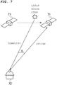
- a technique using a laser guide star has been proposed. Specifically, in order to increase the spatial resolution limited by the atmospheric fluctuation or the like, a bright star is generated near the artificial satellite 71, and measures the atmospheric fluctuations as the laser guide star. Then, the spatial resolution is improved by feeding back the measured atmospheric fluctuation to an adaptive optics system in real time.
- Non-Patent Literature 1 J. Hardy, “Adaptive Optics for Astronomical Telescopes,” Oxford University Press, 1998
- the present invention has been made in view of the above-mentioned problems, and the object thereof is to provide a free-space optical communication apparatus for transmitting and receiving light waves to and from an artificial satellite orbiting an earth orbit, the free-space optical communication apparatus being capable of transmitting uplink light waves with high accuracy by measuring an atmospheric fluctuation with light received from a satellite without using a laser guide star to compensate for the atmospheric fluctuation.
- a free-space optical communication apparatus is a free-space optical communication apparatus for transmitting and receiving light waves to and from an artificial satellite orbiting an earth orbit, the free-space optical communication apparatus including a transmission light wave generating unit configured to generate a transmission light wave to be transmitted to the artificial satellite; a telescope having an aperture for collecting a reception light wave emitted from the artificial satellite, the aperture being adapted to collect a path propagation light propagating through a space including a propagation path for guiding the transmission light wave generated by the transmission light wave generating unit to the artificial satellite; a wavefront sensor configured to detect wavefront distortions of the reception light wave and the path propagation light collected by the telescope; a control unit configured to generate a control signal based on the wavefront distortions detected by the wavefront sensor; and a deformable mirror configured to correct the propagation path based on the control signal generated by the control unit to guide the transmission light wave to the artificial satellite through the telescope.
- the aperture of the telescope has a diameter increased to such an extent that the reception light wave and the path propagation light are received.
- the telescope collects each of the reception light wave and the path propagation light through apertures different from one another.
- the control unit detects atmospheric information of the space including the propagation path from the wavefront distortion, and generates the control signal for correcting the propagation path based on the detected atmospheric information.
- the respective wavefront distortions of the reception light wave and the path propagation light are detected through a plurality of wavefront sensors different from each other.
- a free-space optical communication method is a free-space optical communication method for transmitting and receiving light waves to and from an artificial satellite orbiting an earth orbit, the free-space optical communication method including a transmission light wave generating step of generating a transmission light wave to be transmitted to the artificial satellite; a light collecting step of collecting a reception light wave emitted from the artificial satellite and a path propagation light propagating through a space including a propagation path for guiding the transmission light wave generated by the transmission light wave generating unit to the artificial satellite through a telescope having an aperture; a detecting step of detecting wavefront distortions of the reception light wave and the path propagation light collected at the light collecting step; a control step of generating a control signal based on the wavefront distortions detected at the detecting step; and a correcting step of correcting the propagation path based on the control signal generated at the control step to guide the transmission light wave to the artificial satellite through the telescope.
- an adaptive optics system capable of selecting a propagation path of a transmission light wave Tx taking into consideration the effects of atmospheric fluctuation, fading, and the like, without generating a laser guide star as in the conventional systems.
- a transmission light wave Tx for uplink toward an artificial satellite with high accuracy.
- it is not necessary to mount an adaptive optics system in which a laser guide star is generated it is also possible to provide a simple configuration without complicating the system configuration of the free-space optical communication apparatus.
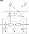
- Fig. 1 illustrates a configuration example of a space communication system 1 to which a free-space optical communication apparatus 2 according to the present invention is applied.
- the space communication system 1 includes an artificial satellite 11 and the free-space optical communication apparatus 2.
- the satellite 11 is an satellite that orbits a geostationary orbit (GEO: Geostationary Earth Orbit), which is a geosynchronous orbit as an earth orbit having an orbital period coincident with the earth's rotation period, that orbits a low orbit (LEO: Low Earth Orbit) or a medium orbit (MEO: Medium Earth Orbit), i.e., independently of the earth's rotation period, or that flies in deep space and the like.
- GEO Geostationary Earth Orbit
- LEO Low Earth Orbit
- MEO Medium Earth Orbit
- the artificial satellite 11 may be launched for any application.
- the artificial satellite 11 is also not limited to those orbiting GEO, LEO, and MEO, but is a concept including any other satellite flying in space.
- the free-space optical communication apparatus 2 transmits and receives an optical signal to and from the artificial satellite 11.
- the free-space optical communication apparatus 2 may be embodied as a telescope.
- the free-space optical communication apparatus 2 is connected to other objects, such as a gateway, a ground communication network installed on the ground, and a communication body such as a vehicle, a ship, and an aircraft, to transmit and receive an optical signal.
- the gateway, the ground communication network, the communication body, and the like transmit and receive optical signals to and from the artificial satellite 11 via the free-space optical communication apparatus 2.
- the free-space optical communication apparatus 2 includes a telescope 20 in which a plurality of apertures 21a to 21d and a sub mirror 22 are formed on the tip end surface of its lens barrel, deformable mirrors 23a and 23b formed at a proximal end portion of the telescope 20, light separation units 24a and 24b provided downstream of the deformable mirrors 23a and 23b, wavefront sensors 25a and 25b provided downstream of the light separation units 24a and 24b, and a control unit 26 connected to the wavefront sensors 25a and 25b and the deformable mirrors 23a and 23b.
- the deformable mirror 23a, the light separation unit 24a, the wavefront sensor 25a, the deformable mirror 23b, the light separation unit 24b, and the wavefront sensor 25b are illustrated separately, they can be provided as one system.
- the telescope 20 is adjusted by a pedestal (not illustrated) so that the longitudinal direction of the lens barrel 20a is directed to the flight direction of the artificial satellite 11.
- the apertures 21a to 21d are provided around the sub mirror 22 formed on the end face of the lens barrel 20a to actually collect or emit an optical signal from or to the artificial satellite 11.
- the apertures 21 through which optical signals are incident from or emitted to the artificial satellite 11 are not limited to the case of being embodied as a plurality of small apertures.
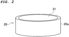
- a single large aperture formed on substantially the entire end face of the lens barrel 20a may be embodied as illustrated in Fig. 2 .
- Each aperture 21 has a lens to play a role of expanding or reducing the focal point of the light to be incident or emitted, as a matter of course.
- the telescope 20 is used not only in the downlink for optical communication from the artificial satellite 11 to the free-space optical communication apparatus 2, but also in the uplink for optical communication from the free-space optical communication apparatus 2 to the artificial satellite 11.
- the system itself can be simplified in that an additional telescope for uplink is not required but the telescope for downlink normally used is shared as it is.
- the configuration of the telescope 20 is not limited to the above-described example, and may be embodied by any existing telescope.
- the deformable mirrors 23a and 23b are configured so that the orientation of the reflecting surfaces of the mirrors becomes constant with respect to the projectile by a tracking function of the pedestal of the telescope 20.
- the orientation and shape of the mirror reflecting surfaces of the deformable mirrors 23a and 23b are controlled based on the control signal transmitted from the control unit 26 so as be freely deformed. Further, controlling the mirror reflecting surfaces of the deformable mirrors 23a and 23b makes it is possible to guide a transmission light wave Tx in the direction of the artificial satellite 11.
- the deformable mirrors 23a and 23b can also finely adjust the propagation path of the transmission light wave Tx based on the control signal described above.
- the light separation units 24a and 24b are configured by a beam splitter, a half mirror, and the like.
- the light separation unit 24a reflects a reception light wave Rx reflected by the deformable mirror 23a and guides the reflected light wave Rx to the wavefront sensor 25a. Further, the light separation unit 24a passes the transmission light wave Tx propagated from the outside as it is to guide it to the deformable mirror 23a.
- the light separation unit 24b passes a part of the reception light wave Rx reflected by the deformable mirror 23b to guide it to the outside, and reflects another part of the reception light wave Rx to guide it to the wavefront sensor 25b.
- the transmission light wave Tx is transmitted in the state where the transmission light axis of the transmission light wave Tx is biased with respect to the reception light axis of the reception light wave Rx by an estimated angle based on the speed of the satellite from the calculation of the obit of the satellite and the like by the deformable mirror 23a and an optical system for the transmission light wave Tx (not illustrated).
- the wavefront sensors 25a and 25b are devices for measuring wavefront distortion (aberration) in real time.
- the wavefront sensor 25a measures the wavefront distortion of the reception light wave from the light separation unit 24a and transmits the measurement result to the control unit 26.
- the wavefront sensor 25b also measures the wavefront distortion of the reception light wave from the light separation unit 24b and transmits the measurement result to the control unit 26.
- the control unit 26 receives the measurement result of the wavefront distortion transmitted from the wavefront sensors 25a and 25b.
- the control unit 26 generates a control signal for controlling the deformable mirrors 23a and 23b based on the transmitted measurement result of the wavefront distortion.
- the control unit 26 transmits the generated control signal to the deformable mirrors 23a and 23b.
- the transmission light wave Tx propagating toward the light separation unit 24a is generated in the above-mentioned, not-illustrated gateway, ground communication network, communication body, and the like.
- the reception light wave Rx passing through the light separation unit 24b is transmitted to the above-mentioned, not-illustrated gateway, ground communication network, communication body, and the like.
- Fig. 3 illustrates propagation paths for downlink of optical communication from the artificial satellite 11 to the free-space optical communication apparatus 2 and for uplink of optical communication from the free-space optical communication apparatus 2 to the artificial satellite 11.
- a space P2 is a propagation space for only the reception light wave Rx for downlink
- a space P3 is a propagation space for only the transmission light wave Tx for uplink.
- the atmospheric information of the spaces P1 and P2 is acquired, and the atmospheric information of the space P3 is also acquired together. Then, based on the acquired atmospheric information of the space P1 and the space P3, the propagation path of the transmission light wave Tx for uplink is corrected.
- the atmospheric information of the space P1 can be acquired by receiving the reception light wave Rx for downlink as described above, but the atmospheric information of the space P3 is acquired by receiving the path propagation light illustrated in Fig. 3 .
- the path propagation light includes any light (electromagnetic wave) as long as it propagates through the space including the propagation path P2 of the transmission light wave Tx.
- the path propagation light is not limited to that includes the entire space P3, but it may include part of the space P3.
- one large aperture 21 formed in the tip end surface of the lens barrel of the telescope 20 may be provided so that the reception light wave Rx for downlink and part or all of the path propagation light are received.
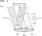
- the plurality of apertures 21a to 21d may be provided so that the reception light wave Rx for downlink and part or all of the path propagation light are received.
- the reception light wave Rx may be received by the one aperture 21a and the transmission light wave Tx may be transmitted through the other one aperture 21d.
- both the reception light wave Rx and the path propagation light received through the aperture 21 are transmitted to the deformable mirrors 23a and 23b.
- the reception light wave Rx is reflected by the deformable mirror 23b, and a part thereof passes through the light separation unit 24b as it is and is transmitted to an external gateway, a ground communication network, a communication body or the like. Further, the other part of the reception light wave Rx is reflected by the light separation unit 24b and reaches the wavefront sensor 25b.
- the path propagation light is bent by the deformable mirror 23b, then reflected by the light separation units 24a and 24b, and reaches the wavefront sensors 25a and 25b.
- reception light wave Rx and the path propagation light reach the wavefront sensors 25a and 25b, their wavefront distortions are detected therein. It becomes possible to acquire atmospheric information based on atmospheric fluctuations or the like in the propagation path of the reception light wave Rx from the detected wavefront distortion. Further, it becomes possible to acquire atmospheric information based on atmospheric fluctuations or the like in the propagation path of the path propagation light from the detected wavefront distortion.
- the wavefront sensors 25a and 25b transmit, to the control unit 26, the wavefront distortions of the reception light wave Rx and the path propagation light on which the atmospheric information is reflected.
- the control unit 26 can acquire atmospheric information of the reception light wave Rx and the path propagation light from the received wavefront distortions. As a result, it is possible to determine the atmospheric information of the spaces P1 and P3 included in the propagation path of the transmission light wave Tx to be transmitted toward the artificial satellite 11 from now.
- the embodiment illustrated in Fig. 1 is merely an example, and the configuration of the deformable mirror 23a and the wavefront sensor 25a may be eliminated so that only the deformable mirror 23b, the light separation unit 24b, and the wavefront sensor 25b perform the processing operation described above, as illustrated in Fig. 5 .
- the reception light wave Rx and the propagation path light are reflected by the deformable mirror 23b, the reception light wave Rx and the propagation path light are separated by the light separation unit 24b, and the path propagation light separated is received by the wavefront sensor 25b.
- part of the reception light wave Rx may be also received by the wavefront sensor 25b.
- the operation of the control unit 26 is the same as described above.
- the same wavefront sensor 25b is used between the transmission light wave Tx and the light separation unit 24b, but another deformable mirror for only the transmission light wave Tx may be inserted therebetween separately from the deformable mirror 23b in order to increase the collection efficiency of the reception light wave Rx.
- three or more sets each including the deformable mirror 23, the light separation unit 24, and the wavefront sensor 25 may be provided so that each set is arranged to be continuous to the control unit.
- a method of determining the atmospheric information is determination using the wavefront distortion.
- the determination may be made from various data such as the magnitude of the wavefront distortion, the fluctuation speed, and the dispersion degree.
- the control unit 26 when the transmission light wave Tx is generated by an external gateway, a ground communication network, or a communication body, it is transmitted through the light separation unit 24a to the deformable mirror 23a.
- the control unit 26 generates a control signal based on the atmospheric information determined as described above.
- the control signal is generated based on the identified wavefront distortions.
- the wavefront distortions also include information on the light reception angles of the reception light wave Rx and the propagation path light at the deformable mirrors 23a and 23b. Furthermore, these wavefront distortions are those on which the atmospheric information is reflected. Thus, by identifying the wavefront distortions, it is possible to indirectly identify the reception angles of the reception light wave Rx and the propagation path light on which the wavefront distortions are reflected and the atmospheric information.
- a control signal for changing the propagation path of the transmission light wave Tx emitted from the telescope 20 is generated based on the wavefront distortions, specifically based on the result of indirectly determining the atmospheric information to which the wavefront distortions are reflected.
- the basis for changing the propagation path is the light reception angles of the original reception light wave Rx and propagation path light, and light reception angles can also be acquired using the wavefront distortions.
- a calibration curve or conversion equation with the wavefront distortion may be prepared in advance based on measured values in the past, etc. so that the actual propagation path of the transmission light wave Tx is determined based on the prepared calibration curve or conversion equation.
- control unit 26 may have any configuration as long as it detects the atmospheric information such as atmospheric fluctuations in the space including the spaces P1 and P3 using the wavefront distortions, and generates a control signal for correcting the propagation path based on the detected atmospheric information. Moreover, the control unit 26 may have any configuration as long as it calculates the angle of the propagation path from the measured wavefront distortion.
- the deformable mirror 23a can receive from the control unit 26 a control signal that is generated to reduce the influence of atmospheric fluctuations and fading, and determine based on the control signal the angle of the propagation path of the transmission light wave Tx.
- the transmission light wave Tx emitted from the telescope 20 propagates in the propagation path in which the influence of atmospheric fluctuations and fading is taken into consideration, and then arrives at the artificial satellite 11.
- the free-space optical communication apparatus 2 to which the present invention is applied makes it possible to provide an adaptive optics system capable of selecting a propagation path of a transmission light wave Tx taking into consideration the effects of atmospheric fluctuation, fading, and the like, without generating a laser guide star as in the conventional systems. As a result, it is possible to transmit the transmission light wave Tx for uplink toward the artificial satellite 11 with high accuracy.
- the present invention is not limited to the above-described embodiments, and may be configured to acquire the atmospheric information based on only the information of the path propagation light with eliminating the information of the reception light wave Rx.
- the control signal is generated based on the atmospheric information of only the space P3, but the same effect can be obtained even in such a case.
- the present invention is not limited thereto, and any number of them may be used as long as it is one or more.
- control unit 26 may generate a control signal for correcting the propagation path of the reception light wave Rx for downlink based on the wavefront distortion of the reception light wave Rx.
- the free-space optical communication apparatus 2 is not limited to the case where it is installed on the ground, and may be mounted in another communication body, including a vehicle, a ship, an aircraft, and the like, which transmits and receives optical signals for downlink and uplink to and from the artificial satellite 11. In this case, it is possible to transmit and receive optical signals to and from the other communication body by mounting therein an apparatus that matches the conditions with the free-space optical communication apparatus 2.
- the present invention configured as described above, it is possible to more reliably prevent the propagation path of the transmission light wave Tx for uplink to be shifted due to the influence of the atmosphere and to be dispersed accordingly.
- the power of the transmission light wave Tx has to be increased in consideration of dispersion of the transmission light wave Tx for uplink due to the influence of the atmosphere, but the present invention does not require to force the power of the transmission light wave Tx to increase. As a result, it is possible to reduce the transmission power of the transmission light wave Tx.
- the present invention makes it possible to solve the problem that it is difficult to correct the laser due to atmospheric fluctuations in a spatially uncorrelated angle or more, which is above the Isoplanatic Angle ⁇ 0 , and not to require to force a laser guide star to change in real time for use within the Isoplanatic Angle ⁇ 0 angle as in the prior art, and accordingly to reduce the system load.
Landscapes
- Engineering & Computer Science (AREA)
- Physics & Mathematics (AREA)
- Electromagnetism (AREA)
- Computer Networks & Wireless Communication (AREA)
- Signal Processing (AREA)
- Astronomy & Astrophysics (AREA)
- General Physics & Mathematics (AREA)
- Remote Sensing (AREA)
- Aviation & Aerospace Engineering (AREA)
- Radar, Positioning & Navigation (AREA)
- Optical Communication System (AREA)
- Optics & Photonics (AREA)
Abstract
Description
- The present invention relates to free-space optical communication apparatuses and methods for transmitting and receiving light waves to and from an artificial satellite orbiting the earth, and particularly to a free-space optical communication apparatus and a method suitable for improving the connectivity of ground-satellite links especially even under atmospheric fluctuations.
- In recent years, research has been advanced to perform optical satellite communication between a ground station on the earth and an artificial satellite or the like orbiting the earth in space. Such optical satellite communication is capable of large-capacity data transmission, can be realized with a lightweight, compact system configuration, and has also advantages such as less interference compared to using radio waves, so it has attracted attention as technology for future space communication.
- Such optical satellite communication has, in an
artificial satellite 71 and aground station 72 as illustrated inFig. 6 , a downlink for optical communication from theartificial satellite 71 to theground station 72, and an uplink for optical communication from theground station 72 to theartificial satellite 71. After downlink light waves are transmitted from thesatellite 71 to theground station 72 and before uplink light waves transmitted from theground station 72 in response to receiving the downlink light waves arrives at thesatellite 71, the satellite moves restrictively. It takes, for example, a few tenths of a second for the light waves to reach a geosynchronous orbit satellite, taking into account light traveling at a constant speed. For this reason, as illustrated inFig. 6 , even when the uplink light waves are emitted in the same direction as the incident direction of the downlink light waves, the artificial satellite moves in a few tenths of a second. Thus, theartificial light satellite 71 cannot be captured within the range of Isoplanatic Angle θ0 where it is considered that the wavefront of the uplink light waves has the same shape of fluctuations. In addition to this, the optical satellite communication is clearly affected by the effect of the atmosphere due to fluctuations in the air and the like which cause the fading and the instantaneous interruption of the optical link, thereby disturbing the uplink light waves, resulting in distorted wavefront. - For this reason, various adaptive optics techniques have been conventionally proposed in order to correct the propagation direction of the uplink light waves toward the
artificial satellite 71 and to reduce the adverse effect of the atmosphere. - As one of them, as illustrated in
Fig. 7 , a technique using a laser guide star has been proposed. Specifically, in order to increase the spatial resolution limited by the atmospheric fluctuation or the like, a bright star is generated near theartificial satellite 71, and measures the atmospheric fluctuations as the laser guide star. Then, the spatial resolution is improved by feeding back the measured atmospheric fluctuation to an adaptive optics system in real time. - Non-Patent Literature 1: J. Hardy, "Adaptive Optics for Astronomical Telescopes," Oxford University Press, 1998
- Incidentally, such a technique using a laser guide star requires another high-power laser installed for transmitting uplink light waves to generate a laser guide star, and then execute the processing operations described above. For this reason, there is a problem that the system of the ground station is complicated accordingly. Therefore, to date, there has been a demand for a technique capable of measuring atmospheric fluctuation with light received from a satellite without using such a laser guide star and feeding back the resulting atmospheric fluctuation to the adaptive optics system.
- In particular, it cannot be sensed unless the light from the laser guide star is strong to a certain extent. For this reason, there are problems that it is very difficult to generate the laser guide star; and if it is generated continuously, the laser output also increases and the signal-to-noise ratio (S/N ratio) of the received optical signal for communication decreases, thereby making the system itself complicated.
- Therefore, the present invention has been made in view of the above-mentioned problems, and the object thereof is to provide a free-space optical communication apparatus for transmitting and receiving light waves to and from an artificial satellite orbiting an earth orbit, the free-space optical communication apparatus being capable of transmitting uplink light waves with high accuracy by measuring an atmospheric fluctuation with light received from a satellite without using a laser guide star to compensate for the atmospheric fluctuation.
- A free-space optical communication apparatus according to a first invention is a free-space optical communication apparatus for transmitting and receiving light waves to and from an artificial satellite orbiting an earth orbit, the free-space optical communication apparatus including a transmission light wave generating unit configured to generate a transmission light wave to be transmitted to the artificial satellite; a telescope having an aperture for collecting a reception light wave emitted from the artificial satellite, the aperture being adapted to collect a path propagation light propagating through a space including a propagation path for guiding the transmission light wave generated by the transmission light wave generating unit to the artificial satellite; a wavefront sensor configured to detect wavefront distortions of the reception light wave and the path propagation light collected by the telescope; a control unit configured to generate a control signal based on the wavefront distortions detected by the wavefront sensor; and a deformable mirror configured to correct the propagation path based on the control signal generated by the control unit to guide the transmission light wave to the artificial satellite through the telescope.
- In a free-space optical communication apparatus according to a second invention, as set forth in the first invention, the aperture of the telescope has a diameter increased to such an extent that the reception light wave and the path propagation light are received.
- In a free-space optical communication apparatus according to a third invention, as set forth in the first invention, the telescope collects each of the reception light wave and the path propagation light through apertures different from one another.
- In a free-space optical communication apparatus according to a fourth invention, as set forth in the first to third inventions, the control unit detects atmospheric information of the space including the propagation path from the wavefront distortion, and generates the control signal for correcting the propagation path based on the detected atmospheric information.
- In a free-space optical communication apparatus according to a fifth invention, as set forth in the first to fourth inventions, the respective wavefront distortions of the reception light wave and the path propagation light are detected through a plurality of wavefront sensors different from each other.
- A free-space optical communication method according to a sixth invention is a free-space optical communication method for transmitting and receiving light waves to and from an artificial satellite orbiting an earth orbit, the free-space optical communication method including a transmission light wave generating step of generating a transmission light wave to be transmitted to the artificial satellite; a light collecting step of collecting a reception light wave emitted from the artificial satellite and a path propagation light propagating through a space including a propagation path for guiding the transmission light wave generated by the transmission light wave generating unit to the artificial satellite through a telescope having an aperture; a detecting step of detecting wavefront distortions of the reception light wave and the path propagation light collected at the light collecting step; a control step of generating a control signal based on the wavefront distortions detected at the detecting step; and a correcting step of correcting the propagation path based on the control signal generated at the control step to guide the transmission light wave to the artificial satellite through the telescope.
- According to the present invention having the above-described configuration, there is provided an adaptive optics system capable of selecting a propagation path of a transmission light wave Tx taking into consideration the effects of atmospheric fluctuation, fading, and the like, without generating a laser guide star as in the conventional systems. As a result, it is possible to transmit the transmission light wave Tx for uplink toward an artificial satellite with high accuracy. Further, since it is not necessary to mount an adaptive optics system in which a laser guide star is generated, it is also possible to provide a simple configuration without complicating the system configuration of the free-space optical communication apparatus. In addition to this, according to the present invention, it is possible to reliably transmit the transmission light wave Tx to the artificial satellite while reducing the transmission power of the transmission light wave Tx for uplink.
-
-
Fig. 1 is a diagram illustrating a configuration example of a space communication system to which a free-space optical communication apparatus according to the the present invention is applied. -
Fig. 2 is a diagram illustrating another configuration example of a telescope. -
Fig. 3 is a diagram for describing propagation paths for downlink and uplink. -
Fig. 4 is a diagram illustrating another aspect of receiving reception light waves and path propagation light. -
Fig. 5 is a view for describing another embodiment of a space communication system to which the free-space optical communication apparatus according to the present invention is applied. -
Fig. 6 is a diagram for describing a general concept of optical space communication. -
Fig. 7 is a diagram for describing an example of measuring an atmospheric fluctuation using a laser guide star. - Embodiments of the present invention will be described below in detail with reference to the drawings.
-
Fig. 1 illustrates a configuration example of aspace communication system 1 to which a free-spaceoptical communication apparatus 2 according to the present invention is applied. Thespace communication system 1 includes anartificial satellite 11 and the free-spaceoptical communication apparatus 2. - The
satellite 11 is an satellite that orbits a geostationary orbit (GEO: Geostationary Earth Orbit), which is a geosynchronous orbit as an earth orbit having an orbital period coincident with the earth's rotation period, that orbits a low orbit (LEO: Low Earth Orbit) or a medium orbit (MEO: Medium Earth Orbit), i.e., independently of the earth's rotation period, or that flies in deep space and the like. Theartificial satellite 11 may be launched for any application. Theartificial satellite 11 is also not limited to those orbiting GEO, LEO, and MEO, but is a concept including any other satellite flying in space. - The free-space
optical communication apparatus 2 transmits and receives an optical signal to and from theartificial satellite 11. The free-spaceoptical communication apparatus 2 may be embodied as a telescope. The free-spaceoptical communication apparatus 2 is connected to other objects, such as a gateway, a ground communication network installed on the ground, and a communication body such as a vehicle, a ship, and an aircraft, to transmit and receive an optical signal. In other words, the gateway, the ground communication network, the communication body, and the like transmit and receive optical signals to and from theartificial satellite 11 via the free-spaceoptical communication apparatus 2. - As illustrated in
Fig. 1 , the free-spaceoptical communication apparatus 2 includes atelescope 20 in which a plurality ofapertures 21a to 21d and asub mirror 22 are formed on the tip end surface of its lens barrel,deformable mirrors telescope 20,light separation units deformable mirrors wavefront sensors light separation units control unit 26 connected to thewavefront sensors deformable mirrors deformable mirror 23a, thelight separation unit 24a, thewavefront sensor 25a, thedeformable mirror 23b, thelight separation unit 24b, and thewavefront sensor 25b are illustrated separately, they can be provided as one system. - It is noted that the configuration of the
sub mirror 22 in thetelescope 20 may be eliminated. - The
telescope 20 is adjusted by a pedestal (not illustrated) so that the longitudinal direction of thelens barrel 20a is directed to the flight direction of theartificial satellite 11. Theapertures 21a to 21d are provided around thesub mirror 22 formed on the end face of thelens barrel 20a to actually collect or emit an optical signal from or to theartificial satellite 11. Incidentally, theapertures 21 through which optical signals are incident from or emitted to theartificial satellite 11 are not limited to the case of being embodied as a plurality of small apertures. In place of theapertures 21, a single large aperture formed on substantially the entire end face of thelens barrel 20a may be embodied as illustrated inFig. 2 . Eachaperture 21 has a lens to play a role of expanding or reducing the focal point of the light to be incident or emitted, as a matter of course. - That is, the
telescope 20 is used not only in the downlink for optical communication from theartificial satellite 11 to the free-spaceoptical communication apparatus 2, but also in the uplink for optical communication from the free-spaceoptical communication apparatus 2 to theartificial satellite 11. In other words, there is an advantage that the system itself can be simplified in that an additional telescope for uplink is not required but the telescope for downlink normally used is shared as it is. - It is noted that the configuration of the
telescope 20 is not limited to the above-described example, and may be embodied by any existing telescope. - The deformable mirrors 23a and 23b are configured so that the orientation of the reflecting surfaces of the mirrors becomes constant with respect to the projectile by a tracking function of the pedestal of the
telescope 20. The orientation and shape of the mirror reflecting surfaces of the deformable mirrors 23a and 23b are controlled based on the control signal transmitted from thecontrol unit 26 so as be freely deformed. Further, controlling the mirror reflecting surfaces of the deformable mirrors 23a and 23b makes it is possible to guide a transmission light wave Tx in the direction of theartificial satellite 11. The deformable mirrors 23a and 23b can also finely adjust the propagation path of the transmission light wave Tx based on the control signal described above. - The
light separation units light separation unit 24a reflects a reception light wave Rx reflected by thedeformable mirror 23a and guides the reflected light wave Rx to thewavefront sensor 25a. Further, thelight separation unit 24a passes the transmission light wave Tx propagated from the outside as it is to guide it to thedeformable mirror 23a. Thelight separation unit 24b passes a part of the reception light wave Rx reflected by thedeformable mirror 23b to guide it to the outside, and reflects another part of the reception light wave Rx to guide it to thewavefront sensor 25b. By introducing suchlight separating sections single telescope 20 and to separate the path propagation light. The transmission light wave Tx is transmitted in the state where the transmission light axis of the transmission light wave Tx is biased with respect to the reception light axis of the reception light wave Rx by an estimated angle based on the speed of the satellite from the calculation of the obit of the satellite and the like by thedeformable mirror 23a and an optical system for the transmission light wave Tx (not illustrated). - The
wavefront sensors wavefront sensor 25a measures the wavefront distortion of the reception light wave from thelight separation unit 24a and transmits the measurement result to thecontrol unit 26. Thewavefront sensor 25b also measures the wavefront distortion of the reception light wave from thelight separation unit 24b and transmits the measurement result to thecontrol unit 26. - The
control unit 26 receives the measurement result of the wavefront distortion transmitted from thewavefront sensors control unit 26 generates a control signal for controlling the deformable mirrors 23a and 23b based on the transmitted measurement result of the wavefront distortion. Thecontrol unit 26 transmits the generated control signal to the deformable mirrors 23a and 23b. - The transmission light wave Tx propagating toward the
light separation unit 24a is generated in the above-mentioned, not-illustrated gateway, ground communication network, communication body, and the like. On the other hand, the reception light wave Rx passing through thelight separation unit 24b is transmitted to the above-mentioned, not-illustrated gateway, ground communication network, communication body, and the like. - Next, a processing operation method for the free-space
optical communication apparatus 2 having the above-described configuration will be described. -
Fig. 3 illustrates propagation paths for downlink of optical communication from theartificial satellite 11 to the free-spaceoptical communication apparatus 2 and for uplink of optical communication from the free-spaceoptical communication apparatus 2 to theartificial satellite 11. - It takes a few tenths of a second, taking into account light traveling at a constant speed, from the transmission of the reception light wave Rx for downlink from the
artificial satellite 11 to the free-spaceoptical communication apparatus 2 to the arrival of the transmission light wave Tx for uplink transmitted from the free-spaceoptical communication apparatus 2 in response to receiving the reception light wave Rx to theartificial satellite 11. For this reason, as illustrated inFig. 3 , even when the transmission light wave Tx for uplink is emitted in the same direction as the incident direction of the reception light wave Rx for downlink, the artificial satellite moves in a few tenths of a second. For this reason, as illustrated inFig. 3 , the propagation path of the transmission light wave Tx for uplink is different from the propagation path of the reception light wave Rx for downlink, and they are mutually offset by a predetermined angle. - As a result, the propagation path of the transmission light wave Tx for uplink and the propagation path of the reception light wave Rx for downlink overlap in a space P1. On the other hand, a space P2 is a propagation space for only the reception light wave Rx for downlink, and a space P3 is a propagation space for only the transmission light wave Tx for uplink.
- For this reason, what is meant by receiving only the reception light wave Rx for downlink is the state where only the light (electromagnetic wave) propagating through the spaces P1 and P2 in
Fig. 3 is received but the information of the light (electromagnetic wave) in the space P3 is not received. Therefore, it is impossible to acquire the information (hereinafter referred to as atmospheric information) of light (electromagnetic wave) on which the effects such as atmospheric fluctuations which cause the fading and instantaneous interruption of the optical link in the space P3 are reflected. In particular, although the transmission light wave Tx for uplink is affected less by atmospheric fluctuations as it arrives at an upper layer, the time for and distance of propagating through the space P3 rather than the space P1 become longer depending on the condition of the speed of the projectile. - For this reason, in the present invention, by receiving the reception light wave Rx for downlink, the atmospheric information of the spaces P1 and P2 is acquired, and the atmospheric information of the space P3 is also acquired together. Then, based on the acquired atmospheric information of the space P1 and the space P3, the propagation path of the transmission light wave Tx for uplink is corrected.
- Actually, the atmospheric information of the space P1 can be acquired by receiving the reception light wave Rx for downlink as described above, but the atmospheric information of the space P3 is acquired by receiving the path propagation light illustrated in
Fig. 3 . The path propagation light includes any light (electromagnetic wave) as long as it propagates through the space including the propagation path P2 of the transmission light wave Tx. The path propagation light is not limited to that includes the entire space P3, but it may include part of the space P3. - In order to receive such path propagation light, as illustrated in
Fig. 2 , onelarge aperture 21 formed in the tip end surface of the lens barrel of thetelescope 20 may be provided so that the reception light wave Rx for downlink and part or all of the path propagation light are received. Alternatively, as illustrated inFig. 4 , the plurality ofapertures 21a to 21d may be provided so that the reception light wave Rx for downlink and part or all of the path propagation light are received. - As illustrated in
Fig. 3 , the range of acquiring the reception light wave Rx and the propagation path light may be considered mainly a range of 20 km from the ground mainly affected by at least the atmosphere. For example, if a difference in angle between the propagation path of the reception light wave Rx for downlink and the propagation path of the transmission light wave Tx for uplink is 20 µrad, it is understood that theaperture 21 needs to be enlarged by 20 km × 20 µrad = 40 cm. - In the embodiment illustrated in
Fig. 3 , the example in which the downlink light wave and the uplink light wave are transmitted and received through thesame aperture 21 as illustrated inFig. 2 has been described, but the invention is limited thereto. For example, the reception light wave Rx may be received by the oneaperture 21a and the transmission light wave Tx may be transmitted through the other oneaperture 21d. - Thus, both the reception light wave Rx and the path propagation light received through the
aperture 21 are transmitted to the deformable mirrors 23a and 23b. - Among them, the reception light wave Rx is reflected by the
deformable mirror 23b, and a part thereof passes through thelight separation unit 24b as it is and is transmitted to an external gateway, a ground communication network, a communication body or the like. Further, the other part of the reception light wave Rx is reflected by thelight separation unit 24b and reaches thewavefront sensor 25b. - On the other hand, the path propagation light is bent by the
deformable mirror 23b, then reflected by thelight separation units wavefront sensors - When the reception light wave Rx and the path propagation light reach the
wavefront sensors - The
wavefront sensors control unit 26, the wavefront distortions of the reception light wave Rx and the path propagation light on which the atmospheric information is reflected. - The
control unit 26 can acquire atmospheric information of the reception light wave Rx and the path propagation light from the received wavefront distortions. As a result, it is possible to determine the atmospheric information of the spaces P1 and P3 included in the propagation path of the transmission light wave Tx to be transmitted toward theartificial satellite 11 from now. - It is noted that the embodiment illustrated in
Fig. 1 is merely an example, and the configuration of thedeformable mirror 23a and thewavefront sensor 25a may be eliminated so that only thedeformable mirror 23b, thelight separation unit 24b, and thewavefront sensor 25b perform the processing operation described above, as illustrated inFig. 5 . In such a case, the reception light wave Rx and the propagation path light are reflected by thedeformable mirror 23b, the reception light wave Rx and the propagation path light are separated by thelight separation unit 24b, and the path propagation light separated is received by thewavefront sensor 25b. At this time, part of the reception light wave Rx may be also received by thewavefront sensor 25b. The operation of thecontrol unit 26 is the same as described above. - Further, the
same wavefront sensor 25b is used between the transmission light wave Tx and thelight separation unit 24b, but another deformable mirror for only the transmission light wave Tx may be inserted therebetween separately from thedeformable mirror 23b in order to increase the collection efficiency of the reception light wave Rx. - As another variation, three or more sets each including the deformable mirror 23, the light separation unit 24, and the wavefront sensor 25 may be provided so that each set is arranged to be continuous to the control unit.
- A method of determining the atmospheric information is determination using the wavefront distortion. At this time, the determination may be made from various data such as the magnitude of the wavefront distortion, the fluctuation speed, and the dispersion degree.
- Next, when the transmission light wave Tx is generated by an external gateway, a ground communication network, or a communication body, it is transmitted through the
light separation unit 24a to thedeformable mirror 23a. In such a case, thecontrol unit 26 generates a control signal based on the atmospheric information determined as described above. The control signal is generated based on the identified wavefront distortions. The wavefront distortions also include information on the light reception angles of the reception light wave Rx and the propagation path light at the deformable mirrors 23a and 23b. Furthermore, these wavefront distortions are those on which the atmospheric information is reflected. Thus, by identifying the wavefront distortions, it is possible to indirectly identify the reception angles of the reception light wave Rx and the propagation path light on which the wavefront distortions are reflected and the atmospheric information. - A control signal for changing the propagation path of the transmission light wave Tx emitted from the
telescope 20 is generated based on the wavefront distortions, specifically based on the result of indirectly determining the atmospheric information to which the wavefront distortions are reflected. The basis for changing the propagation path is the light reception angles of the original reception light wave Rx and propagation path light, and light reception angles can also be acquired using the wavefront distortions. As to how much the angle of the propagation path is to be changed, a calibration curve or conversion equation with the wavefront distortion may be prepared in advance based on measured values in the past, etc. so that the actual propagation path of the transmission light wave Tx is determined based on the prepared calibration curve or conversion equation. That is, thecontrol unit 26 may have any configuration as long as it detects the atmospheric information such as atmospheric fluctuations in the space including the spaces P1 and P3 using the wavefront distortions, and generates a control signal for correcting the propagation path based on the detected atmospheric information. Moreover, thecontrol unit 26 may have any configuration as long as it calculates the angle of the propagation path from the measured wavefront distortion. - The
deformable mirror 23a can receive from the control unit 26 a control signal that is generated to reduce the influence of atmospheric fluctuations and fading, and determine based on the control signal the angle of the propagation path of the transmission light wave Tx. As a result, the transmission light wave Tx emitted from thetelescope 20 propagates in the propagation path in which the influence of atmospheric fluctuations and fading is taken into consideration, and then arrives at theartificial satellite 11. - Therefore, the free-space
optical communication apparatus 2 to which the present invention is applied makes it possible to provide an adaptive optics system capable of selecting a propagation path of a transmission light wave Tx taking into consideration the effects of atmospheric fluctuation, fading, and the like, without generating a laser guide star as in the conventional systems. As a result, it is possible to transmit the transmission light wave Tx for uplink toward theartificial satellite 11 with high accuracy. - It is noted that the present invention is not limited to the above-described embodiments, and may be configured to acquire the atmospheric information based on only the information of the path propagation light with eliminating the information of the reception light wave Rx. Thus, the control signal is generated based on the atmospheric information of only the space P3, but the same effect can be obtained even in such a case.
- Further, in the embodiments described above, the case where the two
wavefront sensors - Further, the
control unit 26 may generate a control signal for correcting the propagation path of the reception light wave Rx for downlink based on the wavefront distortion of the reception light wave Rx. By acquiring the atmospheric information of the propagation path of the reception light wave Rx and generating the control signal for correcting the atmospheric information, it becomes possible to correct the propagation path of the reception light wave Rx so that the influence of fluctuations in the air can be removed. - It is noted that the present invention is not limited to the embodiments described above. The free-space
optical communication apparatus 2 is not limited to the case where it is installed on the ground, and may be mounted in another communication body, including a vehicle, a ship, an aircraft, and the like, which transmits and receives optical signals for downlink and uplink to and from theartificial satellite 11. In this case, it is possible to transmit and receive optical signals to and from the other communication body by mounting therein an apparatus that matches the conditions with the free-spaceoptical communication apparatus 2. - According to the present invention configured as described above, it is possible to more reliably prevent the propagation path of the transmission light wave Tx for uplink to be shifted due to the influence of the atmosphere and to be dispersed accordingly. Normally, the power of the transmission light wave Tx has to be increased in consideration of dispersion of the transmission light wave Tx for uplink due to the influence of the atmosphere, but the present invention does not require to force the power of the transmission light wave Tx to increase. As a result, it is possible to reduce the transmission power of the transmission light wave Tx.
- Further, the present invention makes it possible to solve the problem that it is difficult to correct the laser due to atmospheric fluctuations in a spatially uncorrelated angle or more, which is above the Isoplanatic Angle θ0, and not to require to force a laser guide star to change in real time for use within the Isoplanatic Angle θ0 angle as in the prior art, and accordingly to reduce the system load.
-
- 1
- SPACE COMMUNICATION SYSTEM
- 2
- FREE-SPACE OPTICAL COMMUNICATION APPARATUS
- 11
- SATELLITE
- 20
- TELESCOPE
- 21
- APERTURE
- 22
- SUB MIRROR
- 23
- DEFORMABLE MIRROR
- 24
- LIGHT SEPARATION UNIT
- 25
- WAVEFRONT SENSOR
- 26
- CONTROL UNIT
- 71
- SATELLITE
- 72
- GROUND STATION
- P1 TO P3
- SPACE
- Rx
- RECEPTION LIGHT WAVE
- Tx
- TRANSMISSION LIGHT WAVE
Claims (6)
- A free-space optical communication apparatus for transmitting and receiving light waves to and from an artificial satellite orbiting an earth orbit, the free-space optical communication apparatus comprising:a transmission light wave generating unit configured to generate a transmission light wave to be transmitted to the artificial satellite;a telescope having an aperture for collecting a reception light wave emitted from the artificial satellite, the aperture being adapted to collect a path propagation light propagating through a space including a propagation path for guiding the transmission light wave generated by the transmission light wave generating unit to the artificial satellite;a wavefront sensor configured to detect wavefront distortions of the reception light wave and the path propagation light collected by the telescope;a control unit configured to generate a control signal based on the wavefront distortions detected by the wavefront sensor; anda deformable mirror configured to correct the propagation path based on the control signal generated by the control unit to guide the transmission light wave to the artificial satellite through the telescope.
- The free-space optical communication apparatus according to claim 1, wherein the aperture of the telescope has a diameter increased to such an extent that the reception light wave and the path propagation light are received.
- The free-space optical communication apparatus according to claim 1, wherein the telescope collects each of the reception light wave and the path propagation light through apertures different from one another.
- The free-space optical communication apparatus according to any one of claims 1 to 3, wherein the control unit detects atmospheric information of the space including the propagation path from the wavefront distortion, and generates the control signal for correcting the propagation path based on the detected atmospheric information.
- The free-space optical communication apparatus according to any one of claims 1 to 4, wherein the respective wavefront distortions of the reception light wave and the path propagation light are detected through a plurality of wavefront sensors different from each other.
- A free-space optical communication method for transmitting and receiving light waves to and from an artificial satellite orbiting an earth orbit, the free-space optical communication method comprising:a transmission light wave generating step of generating a transmission light wave to be transmitted to the artificial satellite;a light collecting step of collecting a reception light wave emitted from the artificial satellite and a path propagation light propagating through a space including a propagation path for guiding the transmission light wave generated by the transmission light wave generating unit to the artificial satellite through a telescope having an aperture;a detecting step of detecting wavefront distortions of the reception light wave and the path propagation light collected at the light collecting step;a control step of generating a control signal based on the wavefront distortions detected at the detecting step; anda correcting step of correcting the propagation path based on the control signal generated at the control step to guide the transmission light wave to the artificial satellite through the telescope.
Applications Claiming Priority (2)
| Application Number | Priority Date | Filing Date | Title |
|---|---|---|---|
| JP2017012949A JP6920710B2 (en) | 2017-01-27 | 2017-01-27 | Spatial optical communication device and method |
| PCT/JP2018/001562 WO2018139357A1 (en) | 2017-01-27 | 2018-01-19 | Spatial optical communication device and method |
Publications (3)
| Publication Number | Publication Date |
|---|---|
| EP3576318A1 true EP3576318A1 (en) | 2019-12-04 |
| EP3576318A4 EP3576318A4 (en) | 2020-11-04 |
| EP3576318B1 EP3576318B1 (en) | 2023-07-12 |
Family
ID=62978405
Family Applications (1)
| Application Number | Title | Priority Date | Filing Date |
|---|---|---|---|
| EP18745058.0A Active EP3576318B1 (en) | 2017-01-27 | 2018-01-19 | Spatial optical communication device and method |
Country Status (5)
| Country | Link |
|---|---|
| US (1) | US10819429B2 (en) |
| EP (1) | EP3576318B1 (en) |
| JP (1) | JP6920710B2 (en) |
| AU (1) | AU2018213509B2 (en) |
| WO (1) | WO2018139357A1 (en) |
Cited By (2)
| Publication number | Priority date | Publication date | Assignee | Title |
|---|---|---|---|---|
| EP4287526A1 (en) * | 2022-06-02 | 2023-12-06 | General Atomics Synopta GmbH | Method and device for satellite communication |
| FR3159240A1 (en) | 2024-02-13 | 2025-08-15 | Airbus Defence And Space Sas | OPTICAL TERMINAL FOR DETECTING SINGLE PHOTONS |
Families Citing this family (15)
| Publication number | Priority date | Publication date | Assignee | Title |
|---|---|---|---|---|
| WO2020128432A1 (en) | 2018-12-20 | 2020-06-25 | Bae Systems Plc | Improvements in and relating to free-space optical communications |
| GB2580044B (en) * | 2018-12-20 | 2023-02-15 | Bae Systems Plc | Improvements in and relating to free-space optical communications |
| JP7123340B2 (en) * | 2019-08-01 | 2022-08-23 | 国立研究開発法人宇宙航空研究開発機構 | Spatial optical communication device and spatial optical communication method |
| US20220376783A1 (en) * | 2019-11-19 | 2022-11-24 | Nippon Telegraph And Telephone Corporation | Receiver, transceiver, spatial optical frequency transmission system, and spatial optical frequency transmission method |
| US11409099B2 (en) | 2020-02-25 | 2022-08-09 | Honeywell Limited Honeywell Limitée | Optical apparatus |
| US11409089B2 (en) | 2020-02-25 | 2022-08-09 | Honeywell Limited Honeywell Limitée | Optical apparatus |
| US12149285B2 (en) | 2020-06-12 | 2024-11-19 | Nippon Telegraph And Telephone Corporation | Optical wireless communication system and optical wireless communication method |
| US11677469B1 (en) * | 2020-09-23 | 2023-06-13 | Bridgecomm, Inc. | Optical positioning-navigation-timing transceivers and associated methods |
| WO2022246695A1 (en) * | 2021-05-26 | 2022-12-01 | The University Of Hong Kong | Improving classical and quantum free-space communication by adaptive optics and by separating the reference and signal beams |
| CN113815909B (en) * | 2021-09-09 | 2023-10-27 | 中国人民解放军63920部队 | Uplink determination method and device for peer-to-peer mode combined configuration spacecraft |
| IL318573A (en) * | 2022-07-25 | 2025-03-01 | Viasat Inc | Methods and apparatus for optical beam compensation in a satellite communications system |
| WO2024030902A1 (en) * | 2022-08-01 | 2024-02-08 | California Institute Of Technology | Complex-wavefront photonic transceiver processor |
| CN115941042B (en) * | 2023-03-09 | 2023-05-23 | 湖南迈克森伟电子科技有限公司 | Inter-satellite laser communication system |
| EP4459896A1 (en) * | 2023-05-03 | 2024-11-06 | Aalyria Technologies, Inc. | Optical wavelength diversity techniques for free-space optical communication |
| WO2025213281A1 (en) * | 2024-04-12 | 2025-10-16 | National Research Council Of Canada | Method for determining a phase correction to apply to an optical element using focal plane intensity measurements |
Family Cites Families (11)
| Publication number | Priority date | Publication date | Assignee | Title |
|---|---|---|---|---|
| JP2000068934A (en) * | 1998-08-24 | 2000-03-03 | Nec Corp | Optical communication device mounted on satellite |
| US6704331B2 (en) | 2001-04-11 | 2004-03-09 | The Regents Of The University Of California | Synthetic guide star generation |
| US6661546B1 (en) * | 2002-03-28 | 2003-12-09 | Terabeam Corporation | Multi-aperture holographic optical element for illumination sensing in a free space optical communication system |
| US7406263B2 (en) * | 2002-10-17 | 2008-07-29 | Aoptix Technologies | Combined wavefront sensor and data detector for a free space optical communications system with adaptive optics |
| US7286766B2 (en) * | 2003-01-16 | 2007-10-23 | Aoptix Technologies, Inc. | Free space optical communication system with power level management |
| US7593641B2 (en) * | 2003-11-10 | 2009-09-22 | Harris Corporation | System and method of free-space optical satellite communications |
| US7457545B2 (en) | 2004-02-12 | 2008-11-25 | Northrop Grumman Corporation | Process for controlling a Hartmann wavefront sensor (WFS) in an adaptive optic (AO) system |
| JP2009177654A (en) * | 2008-01-28 | 2009-08-06 | National Institute Of Information & Communication Technology | Spatial optical communication device and method |
| JP5664549B2 (en) * | 2009-07-16 | 2015-02-04 | 日本電気株式会社 | Capture device, capture method, and capture program |
| DE102013206064B4 (en) | 2013-04-05 | 2014-12-11 | Deutsches Zentrum für Luft- und Raumfahrt e.V. | A method of establishing bidirectional optical communication between a satellite and a ground station |
| EP3471291A1 (en) | 2017-10-12 | 2019-04-17 | Nederlandse Organisatie voor toegepast- natuurwetenschappelijk onderzoek TNO | Optical satellite communication |
-
2017
- 2017-01-27 JP JP2017012949A patent/JP6920710B2/en active Active
-
2018
- 2018-01-19 WO PCT/JP2018/001562 patent/WO2018139357A1/en not_active Ceased
- 2018-01-19 US US16/481,103 patent/US10819429B2/en active Active
- 2018-01-19 EP EP18745058.0A patent/EP3576318B1/en active Active
- 2018-01-19 AU AU2018213509A patent/AU2018213509B2/en active Active
Cited By (3)
| Publication number | Priority date | Publication date | Assignee | Title |
|---|---|---|---|---|
| EP4287526A1 (en) * | 2022-06-02 | 2023-12-06 | General Atomics Synopta GmbH | Method and device for satellite communication |
| FR3159240A1 (en) | 2024-02-13 | 2025-08-15 | Airbus Defence And Space Sas | OPTICAL TERMINAL FOR DETECTING SINGLE PHOTONS |
| WO2025172648A1 (en) | 2024-02-13 | 2025-08-21 | Airbus Defence And Space Sas | Optical terminal for detecting single photons |
Also Published As
| Publication number | Publication date |
|---|---|
| EP3576318B1 (en) | 2023-07-12 |
| US10819429B2 (en) | 2020-10-27 |
| US20190393956A1 (en) | 2019-12-26 |
| AU2018213509B2 (en) | 2022-01-27 |
| EP3576318A4 (en) | 2020-11-04 |
| WO2018139357A1 (en) | 2018-08-02 |
| JP6920710B2 (en) | 2021-08-18 |
| AU2018213509A1 (en) | 2019-08-15 |
| JP2018121281A (en) | 2018-08-02 |
Similar Documents
| Publication | Publication Date | Title |
|---|---|---|
| US10819429B2 (en) | Free-space optical communication apparatus and method | |
| CN102857294B (en) | Method and device for suppressing signal fading in laser communication from ground to GEO (geosynchronous) satellite | |
| EP3183827B1 (en) | Apparatus and method for reducing signal fading due to atmospheric turbulence | |
| US12519542B2 (en) | Feedforward motion compensation for FSOC terminals | |
| US11018766B2 (en) | Optical satellite communication | |
| CN109728855A (en) | Two-way same-band adaptive optics laser communication optical terminal | |
| US20210351844A1 (en) | Point ahead offset angle for free space optical nodes | |
| US9287978B2 (en) | System and method for communication between two communication platforms | |
| Poliak et al. | Terabit-throughput GEO satellite optical feeder link testbed | |
| US10735093B2 (en) | Optical space communication device and delay adjustment method | |
| US20250330248A1 (en) | Power adjustment of a communication link based on state disturbance estimations | |
| JP7123340B2 (en) | Spatial optical communication device and spatial optical communication method | |
| EP4466807A1 (en) | Method for adjusting an optical link alignment of a first communication device with a remote communication device, and communication device therefor | |
| WO2022246695A1 (en) | Improving classical and quantum free-space communication by adaptive optics and by separating the reference and signal beams | |
| Edwards et al. | Free-space high data rate communications technologies for near terrestrial space |
Legal Events
| Date | Code | Title | Description |
|---|---|---|---|
| STAA | Information on the status of an ep patent application or granted ep patent |
Free format text: STATUS: THE INTERNATIONAL PUBLICATION HAS BEEN MADE |
|
| PUAI | Public reference made under article 153(3) epc to a published international application that has entered the european phase |
Free format text: ORIGINAL CODE: 0009012 |
|
| STAA | Information on the status of an ep patent application or granted ep patent |
Free format text: STATUS: REQUEST FOR EXAMINATION WAS MADE |
|
| 17P | Request for examination filed |
Effective date: 20190719 |
|
| AK | Designated contracting states |
Kind code of ref document: A1 Designated state(s): AL AT BE BG CH CY CZ DE DK EE ES FI FR GB GR HR HU IE IS IT LI LT LU LV MC MK MT NL NO PL PT RO RS SE SI SK SM TR |
|
| AX | Request for extension of the european patent |
Extension state: BA ME |
|
| DAV | Request for validation of the european patent (deleted) | ||
| DAX | Request for extension of the european patent (deleted) | ||
| A4 | Supplementary search report drawn up and despatched |
Effective date: 20201005 |
|
| RIC1 | Information provided on ipc code assigned before grant |
Ipc: B64G 3/00 20060101ALI20200929BHEP Ipc: H04B 10/07 20130101ALI20200929BHEP Ipc: H04B 10/118 20130101AFI20200929BHEP |
|
| STAA | Information on the status of an ep patent application or granted ep patent |
Free format text: STATUS: EXAMINATION IS IN PROGRESS |
|
| 17Q | First examination report despatched |
Effective date: 20210830 |
|
| GRAP | Despatch of communication of intention to grant a patent |
Free format text: ORIGINAL CODE: EPIDOSNIGR1 |
|
| STAA | Information on the status of an ep patent application or granted ep patent |
Free format text: STATUS: GRANT OF PATENT IS INTENDED |
|
| INTG | Intention to grant announced |
Effective date: 20230503 |
|
| GRAS | Grant fee paid |
Free format text: ORIGINAL CODE: EPIDOSNIGR3 |
|
| GRAA | (expected) grant |
Free format text: ORIGINAL CODE: 0009210 |
|
| STAA | Information on the status of an ep patent application or granted ep patent |
Free format text: STATUS: THE PATENT HAS BEEN GRANTED |
|
| AK | Designated contracting states |
Kind code of ref document: B1 Designated state(s): AL AT BE BG CH CY CZ DE DK EE ES FI FR GB GR HR HU IE IS IT LI LT LU LV MC MK MT NL NO PL PT RO RS SE SI SK SM TR |
|
| REG | Reference to a national code |
Ref country code: CH Ref legal event code: EP |
|
| REG | Reference to a national code |
Ref country code: IE Ref legal event code: FG4D |
|
| REG | Reference to a national code |
Ref country code: DE Ref legal event code: R096 Ref document number: 602018053206 Country of ref document: DE |
|
| REG | Reference to a national code |
Ref country code: LT Ref legal event code: MG9D |
|
| REG | Reference to a national code |
Ref country code: NL Ref legal event code: MP Effective date: 20230712 |
|
| REG | Reference to a national code |
Ref country code: AT Ref legal event code: MK05 Ref document number: 1588206 Country of ref document: AT Kind code of ref document: T Effective date: 20230712 |
|
| PG25 | Lapsed in a contracting state [announced via postgrant information from national office to epo] |
Ref country code: NL Free format text: LAPSE BECAUSE OF FAILURE TO SUBMIT A TRANSLATION OF THE DESCRIPTION OR TO PAY THE FEE WITHIN THE PRESCRIBED TIME-LIMIT Effective date: 20230712 |
|
| PG25 | Lapsed in a contracting state [announced via postgrant information from national office to epo] |
Ref country code: GR Free format text: LAPSE BECAUSE OF FAILURE TO SUBMIT A TRANSLATION OF THE DESCRIPTION OR TO PAY THE FEE WITHIN THE PRESCRIBED TIME-LIMIT Effective date: 20231013 |
|
| PG25 | Lapsed in a contracting state [announced via postgrant information from national office to epo] |
Ref country code: ES Free format text: LAPSE BECAUSE OF FAILURE TO SUBMIT A TRANSLATION OF THE DESCRIPTION OR TO PAY THE FEE WITHIN THE PRESCRIBED TIME-LIMIT Effective date: 20230712 |
|
| PG25 | Lapsed in a contracting state [announced via postgrant information from national office to epo] |
Ref country code: IS Free format text: LAPSE BECAUSE OF FAILURE TO SUBMIT A TRANSLATION OF THE DESCRIPTION OR TO PAY THE FEE WITHIN THE PRESCRIBED TIME-LIMIT Effective date: 20231112 |
|
| PG25 | Lapsed in a contracting state [announced via postgrant information from national office to epo] |
Ref country code: SE Free format text: LAPSE BECAUSE OF FAILURE TO SUBMIT A TRANSLATION OF THE DESCRIPTION OR TO PAY THE FEE WITHIN THE PRESCRIBED TIME-LIMIT Effective date: 20230712 Ref country code: RS Free format text: LAPSE BECAUSE OF FAILURE TO SUBMIT A TRANSLATION OF THE DESCRIPTION OR TO PAY THE FEE WITHIN THE PRESCRIBED TIME-LIMIT Effective date: 20230712 Ref country code: PT Free format text: LAPSE BECAUSE OF FAILURE TO SUBMIT A TRANSLATION OF THE DESCRIPTION OR TO PAY THE FEE WITHIN THE PRESCRIBED TIME-LIMIT Effective date: 20231113 Ref country code: NO Free format text: LAPSE BECAUSE OF FAILURE TO SUBMIT A TRANSLATION OF THE DESCRIPTION OR TO PAY THE FEE WITHIN THE PRESCRIBED TIME-LIMIT Effective date: 20231012 Ref country code: LV Free format text: LAPSE BECAUSE OF FAILURE TO SUBMIT A TRANSLATION OF THE DESCRIPTION OR TO PAY THE FEE WITHIN THE PRESCRIBED TIME-LIMIT Effective date: 20230712 Ref country code: LT Free format text: LAPSE BECAUSE OF FAILURE TO SUBMIT A TRANSLATION OF THE DESCRIPTION OR TO PAY THE FEE WITHIN THE PRESCRIBED TIME-LIMIT Effective date: 20230712 Ref country code: IS Free format text: LAPSE BECAUSE OF FAILURE TO SUBMIT A TRANSLATION OF THE DESCRIPTION OR TO PAY THE FEE WITHIN THE PRESCRIBED TIME-LIMIT Effective date: 20231112 Ref country code: HR Free format text: LAPSE BECAUSE OF FAILURE TO SUBMIT A TRANSLATION OF THE DESCRIPTION OR TO PAY THE FEE WITHIN THE PRESCRIBED TIME-LIMIT Effective date: 20230712 Ref country code: GR Free format text: LAPSE BECAUSE OF FAILURE TO SUBMIT A TRANSLATION OF THE DESCRIPTION OR TO PAY THE FEE WITHIN THE PRESCRIBED TIME-LIMIT Effective date: 20231013 Ref country code: FI Free format text: LAPSE BECAUSE OF FAILURE TO SUBMIT A TRANSLATION OF THE DESCRIPTION OR TO PAY THE FEE WITHIN THE PRESCRIBED TIME-LIMIT Effective date: 20230712 Ref country code: ES Free format text: LAPSE BECAUSE OF FAILURE TO SUBMIT A TRANSLATION OF THE DESCRIPTION OR TO PAY THE FEE WITHIN THE PRESCRIBED TIME-LIMIT Effective date: 20230712 Ref country code: AT Free format text: LAPSE BECAUSE OF FAILURE TO SUBMIT A TRANSLATION OF THE DESCRIPTION OR TO PAY THE FEE WITHIN THE PRESCRIBED TIME-LIMIT Effective date: 20230712 |
|
| PG25 | Lapsed in a contracting state [announced via postgrant information from national office to epo] |
Ref country code: PL Free format text: LAPSE BECAUSE OF FAILURE TO SUBMIT A TRANSLATION OF THE DESCRIPTION OR TO PAY THE FEE WITHIN THE PRESCRIBED TIME-LIMIT Effective date: 20230712 |
|
| REG | Reference to a national code |
Ref country code: DE Ref legal event code: R097 Ref document number: 602018053206 Country of ref document: DE |
|
| PG25 | Lapsed in a contracting state [announced via postgrant information from national office to epo] |
Ref country code: SM Free format text: LAPSE BECAUSE OF FAILURE TO SUBMIT A TRANSLATION OF THE DESCRIPTION OR TO PAY THE FEE WITHIN THE PRESCRIBED TIME-LIMIT Effective date: 20230712 Ref country code: RO Free format text: LAPSE BECAUSE OF FAILURE TO SUBMIT A TRANSLATION OF THE DESCRIPTION OR TO PAY THE FEE WITHIN THE PRESCRIBED TIME-LIMIT Effective date: 20230712 Ref country code: EE Free format text: LAPSE BECAUSE OF FAILURE TO SUBMIT A TRANSLATION OF THE DESCRIPTION OR TO PAY THE FEE WITHIN THE PRESCRIBED TIME-LIMIT Effective date: 20230712 Ref country code: DK Free format text: LAPSE BECAUSE OF FAILURE TO SUBMIT A TRANSLATION OF THE DESCRIPTION OR TO PAY THE FEE WITHIN THE PRESCRIBED TIME-LIMIT Effective date: 20230712 Ref country code: CZ Free format text: LAPSE BECAUSE OF FAILURE TO SUBMIT A TRANSLATION OF THE DESCRIPTION OR TO PAY THE FEE WITHIN THE PRESCRIBED TIME-LIMIT Effective date: 20230712 Ref country code: SK Free format text: LAPSE BECAUSE OF FAILURE TO SUBMIT A TRANSLATION OF THE DESCRIPTION OR TO PAY THE FEE WITHIN THE PRESCRIBED TIME-LIMIT Effective date: 20230712 |
|
| PLBE | No opposition filed within time limit |
Free format text: ORIGINAL CODE: 0009261 |
|
| STAA | Information on the status of an ep patent application or granted ep patent |
Free format text: STATUS: NO OPPOSITION FILED WITHIN TIME LIMIT |
|
| PG25 | Lapsed in a contracting state [announced via postgrant information from national office to epo] |
Ref country code: IT Free format text: LAPSE BECAUSE OF FAILURE TO SUBMIT A TRANSLATION OF THE DESCRIPTION OR TO PAY THE FEE WITHIN THE PRESCRIBED TIME-LIMIT Effective date: 20230712 |
|
| 26N | No opposition filed |
Effective date: 20240415 |
|
| PG25 | Lapsed in a contracting state [announced via postgrant information from national office to epo] |
Ref country code: SI Free format text: LAPSE BECAUSE OF FAILURE TO SUBMIT A TRANSLATION OF THE DESCRIPTION OR TO PAY THE FEE WITHIN THE PRESCRIBED TIME-LIMIT Effective date: 20230712 |
|
| REG | Reference to a national code |
Ref country code: DE Ref legal event code: R119 Ref document number: 602018053206 Country of ref document: DE |
|
| PG25 | Lapsed in a contracting state [announced via postgrant information from national office to epo] |
Ref country code: MC Free format text: LAPSE BECAUSE OF FAILURE TO SUBMIT A TRANSLATION OF THE DESCRIPTION OR TO PAY THE FEE WITHIN THE PRESCRIBED TIME-LIMIT Effective date: 20230712 |
|
| PG25 | Lapsed in a contracting state [announced via postgrant information from national office to epo] |
Ref country code: MC Free format text: LAPSE BECAUSE OF FAILURE TO SUBMIT A TRANSLATION OF THE DESCRIPTION OR TO PAY THE FEE WITHIN THE PRESCRIBED TIME-LIMIT Effective date: 20230712 |
|
| PG25 | Lapsed in a contracting state [announced via postgrant information from national office to epo] |
Ref country code: LU Free format text: LAPSE BECAUSE OF NON-PAYMENT OF DUE FEES Effective date: 20240119 |
|
| GBPC | Gb: european patent ceased through non-payment of renewal fee |
Effective date: 20240119 |
|
| PG25 | Lapsed in a contracting state [announced via postgrant information from national office to epo] |
Ref country code: LU Free format text: LAPSE BECAUSE OF NON-PAYMENT OF DUE FEES Effective date: 20240119 |
|
| PG25 | Lapsed in a contracting state [announced via postgrant information from national office to epo] |
Ref country code: DE Free format text: LAPSE BECAUSE OF NON-PAYMENT OF DUE FEES Effective date: 20240801 |
|
| PG25 | Lapsed in a contracting state [announced via postgrant information from national office to epo] |
Ref country code: GB Free format text: LAPSE BECAUSE OF NON-PAYMENT OF DUE FEES Effective date: 20240119 |
|
| PG25 | Lapsed in a contracting state [announced via postgrant information from national office to epo] |
Ref country code: BE Free format text: LAPSE BECAUSE OF NON-PAYMENT OF DUE FEES Effective date: 20240131 |
|
| PG25 | Lapsed in a contracting state [announced via postgrant information from national office to epo] |
Ref country code: GB Free format text: LAPSE BECAUSE OF NON-PAYMENT OF DUE FEES Effective date: 20240119 Ref country code: DE Free format text: LAPSE BECAUSE OF NON-PAYMENT OF DUE FEES Effective date: 20240801 Ref country code: BE Free format text: LAPSE BECAUSE OF NON-PAYMENT OF DUE FEES Effective date: 20240131 |
|
| REG | Reference to a national code |
Ref country code: BE Ref legal event code: MM Effective date: 20240131 |
|
| PG25 | Lapsed in a contracting state [announced via postgrant information from national office to epo] |
Ref country code: BG Free format text: LAPSE BECAUSE OF FAILURE TO SUBMIT A TRANSLATION OF THE DESCRIPTION OR TO PAY THE FEE WITHIN THE PRESCRIBED TIME-LIMIT Effective date: 20230712 |
|
| PG25 | Lapsed in a contracting state [announced via postgrant information from national office to epo] |
Ref country code: BG Free format text: LAPSE BECAUSE OF FAILURE TO SUBMIT A TRANSLATION OF THE DESCRIPTION OR TO PAY THE FEE WITHIN THE PRESCRIBED TIME-LIMIT Effective date: 20230712 |
|
| PG25 | Lapsed in a contracting state [announced via postgrant information from national office to epo] |
Ref country code: IE Free format text: LAPSE BECAUSE OF NON-PAYMENT OF DUE FEES Effective date: 20240119 |
|
| PG25 | Lapsed in a contracting state [announced via postgrant information from national office to epo] |
Ref country code: IE Free format text: LAPSE BECAUSE OF NON-PAYMENT OF DUE FEES Effective date: 20240119 |
|
| PG25 | Lapsed in a contracting state [announced via postgrant information from national office to epo] |
Ref country code: CY Free format text: LAPSE BECAUSE OF FAILURE TO SUBMIT A TRANSLATION OF THE DESCRIPTION OR TO PAY THE FEE WITHIN THE PRESCRIBED TIME-LIMIT; INVALID AB INITIO Effective date: 20180119 |
|
| PG25 | Lapsed in a contracting state [announced via postgrant information from national office to epo] |
Ref country code: HU Free format text: LAPSE BECAUSE OF FAILURE TO SUBMIT A TRANSLATION OF THE DESCRIPTION OR TO PAY THE FEE WITHIN THE PRESCRIBED TIME-LIMIT; INVALID AB INITIO Effective date: 20180119 |
|
| PG25 | Lapsed in a contracting state [announced via postgrant information from national office to epo] |
Ref country code: TR Free format text: LAPSE BECAUSE OF FAILURE TO SUBMIT A TRANSLATION OF THE DESCRIPTION OR TO PAY THE FEE WITHIN THE PRESCRIBED TIME-LIMIT Effective date: 20230712 |
|
| REG | Reference to a national code |
Ref country code: CH Ref legal event code: U11 Free format text: ST27 STATUS EVENT CODE: U-0-0-U10-U11 (AS PROVIDED BY THE NATIONAL OFFICE) Effective date: 20260201 |
|
| PGFP | Annual fee paid to national office [announced via postgrant information from national office to epo] |
Ref country code: FR Payment date: 20260123 Year of fee payment: 9 |
|
| PGFP | Annual fee paid to national office [announced via postgrant information from national office to epo] |
Ref country code: CH Payment date: 20260201 Year of fee payment: 9 |