EP3576270A1 - Inverter operation with increased gate driving voltage at high junction temperatures - Google Patents
Inverter operation with increased gate driving voltage at high junction temperatures Download PDFInfo
- Publication number
- EP3576270A1 EP3576270A1 EP18174871.6A EP18174871A EP3576270A1 EP 3576270 A1 EP3576270 A1 EP 3576270A1 EP 18174871 A EP18174871 A EP 18174871A EP 3576270 A1 EP3576270 A1 EP 3576270A1
- Authority
- EP
- European Patent Office
- Prior art keywords
- potential
- control device
- switching element
- switching
- converter
- Prior art date
- Legal status (The legal status is an assumption and is not a legal conclusion. Google has not performed a legal analysis and makes no representation as to the accuracy of the status listed.)
- Withdrawn
Links
Images


Classifications
-
- H—ELECTRICITY
- H02—GENERATION; CONVERSION OR DISTRIBUTION OF ELECTRIC POWER
- H02M—APPARATUS FOR CONVERSION BETWEEN AC AND AC, BETWEEN AC AND DC, OR BETWEEN DC AND DC, AND FOR USE WITH MAINS OR SIMILAR POWER SUPPLY SYSTEMS; CONVERSION OF DC OR AC INPUT POWER INTO SURGE OUTPUT POWER; CONTROL OR REGULATION THEREOF
- H02M1/00—Details of apparatus for conversion
- H02M1/32—Means for protecting converters other than automatic disconnection
-
- H—ELECTRICITY
- H02—GENERATION; CONVERSION OR DISTRIBUTION OF ELECTRIC POWER
- H02M—APPARATUS FOR CONVERSION BETWEEN AC AND AC, BETWEEN AC AND DC, OR BETWEEN DC AND DC, AND FOR USE WITH MAINS OR SIMILAR POWER SUPPLY SYSTEMS; CONVERSION OF DC OR AC INPUT POWER INTO SURGE OUTPUT POWER; CONTROL OR REGULATION THEREOF
- H02M1/00—Details of apparatus for conversion
- H02M1/08—Circuits specially adapted for the generation of control voltages for semiconductor devices incorporated in static converters
-
- H—ELECTRICITY
- H02—GENERATION; CONVERSION OR DISTRIBUTION OF ELECTRIC POWER
- H02M—APPARATUS FOR CONVERSION BETWEEN AC AND AC, BETWEEN AC AND DC, OR BETWEEN DC AND DC, AND FOR USE WITH MAINS OR SIMILAR POWER SUPPLY SYSTEMS; CONVERSION OF DC OR AC INPUT POWER INTO SURGE OUTPUT POWER; CONTROL OR REGULATION THEREOF
- H02M1/00—Details of apparatus for conversion
- H02M1/0048—Circuits or arrangements for reducing losses
-
- H—ELECTRICITY
- H02—GENERATION; CONVERSION OR DISTRIBUTION OF ELECTRIC POWER
- H02M—APPARATUS FOR CONVERSION BETWEEN AC AND AC, BETWEEN AC AND DC, OR BETWEEN DC AND DC, AND FOR USE WITH MAINS OR SIMILAR POWER SUPPLY SYSTEMS; CONVERSION OF DC OR AC INPUT POWER INTO SURGE OUTPUT POWER; CONTROL OR REGULATION THEREOF
- H02M1/00—Details of apparatus for conversion
- H02M1/32—Means for protecting converters other than automatic disconnection
- H02M1/327—Means for protecting converters other than automatic disconnection against abnormal temperatures
-
- H—ELECTRICITY
- H02—GENERATION; CONVERSION OR DISTRIBUTION OF ELECTRIC POWER
- H02M—APPARATUS FOR CONVERSION BETWEEN AC AND AC, BETWEEN AC AND DC, OR BETWEEN DC AND DC, AND FOR USE WITH MAINS OR SIMILAR POWER SUPPLY SYSTEMS; CONVERSION OF DC OR AC INPUT POWER INTO SURGE OUTPUT POWER; CONTROL OR REGULATION THEREOF
- H02M7/00—Conversion of ac power input into dc power output; Conversion of dc power input into ac power output
- H02M7/42—Conversion of dc power input into ac power output without possibility of reversal
- H02M7/44—Conversion of dc power input into ac power output without possibility of reversal by static converters
- H02M7/48—Conversion of dc power input into ac power output without possibility of reversal by static converters using discharge tubes with control electrode or semiconductor devices with control electrode
- H02M7/53—Conversion of dc power input into ac power output without possibility of reversal by static converters using discharge tubes with control electrode or semiconductor devices with control electrode using devices of a triode or transistor type requiring continuous application of a control signal
- H02M7/537—Conversion of dc power input into ac power output without possibility of reversal by static converters using discharge tubes with control electrode or semiconductor devices with control electrode using devices of a triode or transistor type requiring continuous application of a control signal using semiconductor devices only, e.g. single switched pulse inverters
- H02M7/5387—Conversion of dc power input into ac power output without possibility of reversal by static converters using discharge tubes with control electrode or semiconductor devices with control electrode using devices of a triode or transistor type requiring continuous application of a control signal using semiconductor devices only, e.g. single switched pulse inverters in a bridge configuration
-
- H—ELECTRICITY
- H03—ELECTRONIC CIRCUITRY
- H03K—PULSE TECHNIQUE
- H03K17/00—Electronic switching or gating, i.e. not by contact-making and –breaking
- H03K17/06—Modifications for ensuring a fully conducting state
-
- H—ELECTRICITY
- H03—ELECTRONIC CIRCUITRY
- H03K—PULSE TECHNIQUE
- H03K17/00—Electronic switching or gating, i.e. not by contact-making and –breaking
- H03K17/08—Modifications for protecting switching circuit against overcurrent or overvoltage
- H03K2017/0806—Modifications for protecting switching circuit against overcurrent or overvoltage against excessive temperature
-
- Y—GENERAL TAGGING OF NEW TECHNOLOGICAL DEVELOPMENTS; GENERAL TAGGING OF CROSS-SECTIONAL TECHNOLOGIES SPANNING OVER SEVERAL SECTIONS OF THE IPC; TECHNICAL SUBJECTS COVERED BY FORMER USPC CROSS-REFERENCE ART COLLECTIONS [XRACs] AND DIGESTS
- Y02—TECHNOLOGIES OR APPLICATIONS FOR MITIGATION OR ADAPTATION AGAINST CLIMATE CHANGE
- Y02B—CLIMATE CHANGE MITIGATION TECHNOLOGIES RELATED TO BUILDINGS, e.g. HOUSING, HOUSE APPLIANCES OR RELATED END-USER APPLICATIONS
- Y02B70/00—Technologies for an efficient end-user side electric power management and consumption
- Y02B70/10—Technologies improving the efficiency by using switched-mode power supplies [SMPS], i.e. efficient power electronics conversion e.g. power factor correction or reduction of losses in power supplies or efficient standby modes
Abstract
Eine Steuereinrichtung (8) eines Umrichters (1) nimmt getaktet jeweils einen Stromsollwert (I*) entgegen und ermittelt Schaltzeitpunkte (tij) für Schaltelemente (7) des Umrichters (1), so dass der Umrichter (1) einer Last (5) einen mit dem Stromsollwert (I*) korrespondierenden Strom (I) zuführt. Die Steuereinrichtung (8) nimmt Soll- oder Istgrößen (Ik) - entgegen und leitet daraus eine Sperrschichttemperatur (T) der Schaltelemente (7) ab. Die Steuereinrichtung (8) bleibt in einem Normalbetrieb, solange die Sperrschichttemperatur (T) unterhalb einer Grenztemperatur (TGO) bleibt. Anderenfalls wechselt sie in den Sonderbetrieb. Die Steuereinrichtung (8) bleibt im Sonderbetrieb, solange die Sperrschichttemperatur (T) oberhalb einer unteren Grenztemperatur (TGO) bleibt. Anderenfalls wechselt sie in den Normalbetrieb. Wenn die Sperrschichttemperatur (T) im Sonderbetrieb die obere Grenztemperatur (TGO) für längere Zeit erreicht oder überschreitet und/oder nach einem Absinken erneut erreicht oder überschreitet, modifiziert die Steuereinrichtung (8) die Schaltzeitpunkte (tij), so dass der der Last (5) zugeführte Strom (I) kleiner als der Stromsollwert (I*) ist. In beiden Modi sperrt die Steuereinrichtung (8) die Schaltelemente (7) zu den ermittelten Schaltzeitpunkten (tij) jeweils bzw. schaltet sie durch. Zum Sperren schaltet die Steuereinrichtung (8) in beiden Modi ein erstes Potenzial (P1) an eine Steuerelektrode (11) des jeweiligen Schaltelements (7) an, zum Durchschalten im Normalbetrieb ein zweites Potenzial (P2) und im Sonderbetrieb zumindest temporär ein drittes Potenzial (P3) und im Übrigen das zweite Potenzial (P2). Die Differenz des dritten Potenzials (P3) zum ersten Potenzial (P1) ist größer als die Differenz des zweiten Potenzials (P2) zum ersten Potenzial (P1) .A control device (8) of a converter (1) receives a clocked current setpoint (I *) and determines switching times (tij) for switching elements (7) of the converter (1) so that the converter (1) of a load (5) supplies current (I) corresponding to the current setpoint (I *). The control device (8) receives target or actual values (Ik) and derives a junction temperature (T) of the switching elements (7) from them. The control device (8) remains in normal operation as long as the junction temperature (T) remains below a limit temperature (TGO). Otherwise it changes to special mode. The control device (8) remains in special mode as long as the junction temperature (T) remains above a lower limit temperature (TGO). Otherwise it changes to normal operation. If the junction temperature (T) in special operation reaches or exceeds the upper limit temperature (TGO) for a longer period of time and / or reaches or exceeds it again after a drop, the control device (8) modifies the switching times (tij) so that the load (5 ) supplied current (I) is less than the current setpoint (I *). In both modes, the control device (8) blocks the switching elements (7) at the determined switching times (tij) or switches them through. For blocking, the control device (8) connects a first potential (P1) to a control electrode (11) of the respective switching element (7) in both modes, for switching through a second potential (P2) in normal operation and at least temporarily a third potential in special operation ( P3) and the rest of the second potential (P2). The difference between the third potential (P3) and the first potential (P1) is greater than the difference between the second potential (P2) and the first potential (P1).
Description
Die vorliegende Erfindung geht aus von einem Betriebsverfahren für einen eine Last speisenden Umrichter.The present invention is based on an operating method for a load-feeding converter.
Derartige Betriebsverfahren sind allgemein bekannt. Üblicherweise nimmt die Steuereinrichtung getaktet jeweils einen Stromsollwert entgegennimmt und ermittelt Schaltzeitpunkte für Schaltelemente des Umrichters, zu denen die Steuereinrichtung die Schaltelemente alternierend sperrt und durchschaltet. Die Schaltelemente sind als Halbleiter-Bauelemente ausgebildet. Die Ermittlung der Schaltzeitpunkte erfolgt derart, dass der Umrichter der Last einen mit dem Stromsollwert korrespondierenden Strom zuführt. Weiterhin nimmt die Steuereinrichtung Soll- oder Istgrößen - meist Istgrößen - entgegen und leitet daraus eine Sperrschichttemperatur der Schaltelemente ab. Solange die Sperrschichttemperatur eine obere Grenztemperatur nicht erreicht oder überschreitet, behält die Steuereinrichtung die ermittelten Schaltzeitpunkte unverändert bei. Anderenfalls ermittelt sie die Schaltzeitpunkte derart neu, dass der der Last zugeführte Strom kleiner als der Stromsollwert ist. Die Steuereinrichtung sperrt die Schaltelemente zu den ermittelten Schaltzeitpunkten jeweils oder schaltet sie jeweils durch. Zum Sperren eines jeweiligen Schaltelements schaltet die Steuereinrichtung ein erstes Potenzial an eine Steuerelektrode des jeweiligen Schaltelements an, zum Durchschalten ein zweites Potenzial.Such operating methods are well known. Usually, the control device takes clocked each receives a current setpoint and determines switching times for switching elements of the inverter, to which the control device blocks the switching elements alternately and turns on. The switching elements are designed as semiconductor components. The switching times are determined in such a way that the converter supplies a current corresponding to the current setpoint to the load. Furthermore, the control device assumes nominal or actual variables-usually actual values-and derives therefrom a junction temperature of the switching elements. As long as the junction temperature does not reach or exceed an upper limit temperature, the control device retains the determined switching times unchanged. Otherwise, it determines the switching times such that the current supplied to the load is smaller than the current setpoint. The control device blocks the switching elements at the determined switching times in each case or switches them through in each case. For blocking a respective switching element, the control device switches on a first potential to a control electrode of the respective switching element, for switching through a second potential.
Die vorliegende Erfindung geht weiterhin aus von einem Steuerprogramm für eine Steuereinrichtung eines Umrichters, wobei das Steuerprogramm Maschinencode aufweist, der von der Steuereinrichtung abarbeitbar ist, wobei die Abarbeitung des Maschinencodes durch die Steuereinrichtung bewirkt, dass die Steuereinrichtung den Umrichter gemäß einem derartigen Betriebsverfahren betreibt.The present invention is further based on a control program for a control device of an inverter, the control program having machine code that can be executed by the control device, wherein the processing of the machine code by the control device causes the control device to operate the converter according to such an operating method.
Die vorliegende Erfindung geht weiterhin aus von einer Steuereinrichtung für einen Umrichter, wobei die Steuereinrichtung mit einem derartigen Steuerprogramm programmiert ist, so dass die Steuereinrichtung den Umrichter gemäß einem derartigen Betriebsverfahren betreibt.The present invention is further based on a control device for a converter, wherein the control device is programmed with such a control program, so that the control device operates the converter according to such an operating method.
Die vorliegende Erfindung geht weiterhin aus von einem Umrichter, wobei der Umrichter als Halbleiter-Bauelemente ausgebildete Schaltelemente aufweist, über die eine Last gespeist wird, wobei der Umrichter eine derartige Steuereinrichtung aufweist, welche den Umrichter gemäß einem derartigen Betriebsverfahren betreibt.The present invention is further based on a converter, wherein the converter comprises semiconductor elements formed as switching elements, via which a load is fed, wherein the inverter comprises such a control device which operates the inverter according to such an operating method.
Bei einem Umrichter treten im durchgeschalteten Zustand an den Leistungshalbleitern des Umrichters Verluste auf. Aufgrund der Verluste erhöht sich die Sperrschichttemperatur des jeweiligen Halbleiters. Die Sperrschichttemperatur muss jedoch unterhalb eines kritischen Wertes gehalten werden, da anderenfalls der jeweilige Halbleiter und damit der Umrichter irreversibel zerstört würde.In the case of a converter, losses occur in the switched-through state on the power semiconductors of the converter. Due to the losses, the junction temperature of the respective semiconductor increases. However, the junction temperature must be kept below a critical value, otherwise the respective semiconductor and thus the converter would be irreversibly destroyed.
Die am jeweiligen Halbleiterelement auftretende Verlustleistung ergibt sich durch das Produkt des von dem jeweiligen Halbleiterelement geführten Stromes mit der jeweiligen Durchlassspannung. Der Strom ist eine nichtlineare Funktion (Kennlinie) der Durchlassspannung, wobei die Funktion ihrerseits von der Steuerspannung des Halbleiters abhängig ist.The power loss occurring at the respective semiconductor element results from the product of the current conducted by the respective semiconductor element with the respective forward voltage. The current is a non-linear function (characteristic curve) of the forward voltage, the function itself being dependent on the control voltage of the semiconductor.
Wenn die Sperrschichttemperatur die Grenztemperatur erreicht oder überschritten wird, werden im Stand der Technik zum Schutz der Schaltelemente die ermittelten Schaltzeitpunkte derart neu ermittelt, dass der der Last zugeführte Strom kleiner als der Stromsollwert ist. Beispielsweise kann bei einer Pulsweitenmodulation der Anteil reduziert werden, zu dem die Schaltelemente durchgeschaltet sind. Dadurch fließt im Ergebnis ein geringerer Strom, wodurch die anfallende Verlustleistung entsprechend reduziert wird. Aufgrund des verringerten Stromes verringert sich weiterhin auch - wenn auch nur geringfügig - die Durchlassspannung, so dass die anfallende Verlustleistung noch weiter reduziert wird. Dadurch wird die Sperrschichttemperatur reduziert. Vorzugsweise erfolgt die Reduzierung des Stroms nur so weit, dass die Grenztemperatur gerade noch eingehalten wird.When the junction temperature reaches or exceeds the threshold temperature, in the prior art for protecting the switching elements, the determined switching times are redetermined such that the current supplied to the load is smaller than the current setpoint. For example, in the case of pulse width modulation, the proportion to which the switching elements are connected can be reduced. As a result, a lower current flows in the result, whereby the resulting power loss is reduced accordingly. Due to the reduced current continues to decrease - even if only slightly - the forward voltage, so that the resulting power loss even further is reduced. This reduces the junction temperature. Preferably, the reduction of the current takes place only so far that the limit temperature is just kept.
Mit der Reduzierung des der Last zugeführten Stroms unter den Stromsollwert wird - wenn auch zum Schutz des Umrichters - der eigentlich gewünschte Betrieb der Last aufgegeben. Insbesondere wird die Last mit einer geringeren Leistung betrieben als eigentlich gewünscht. Beispielsweise ein Antrieb kann nur ein geringeres Moment als eigentlich gewünscht abgeben.With the reduction of the current supplied to the load below the current setpoint, the actually desired operation of the load is abandoned, albeit to protect the converter. In particular, the load is operated at a lower power than actually desired. For example, a drive can deliver only a lesser moment than actually desired.
Die Aufgabe der vorliegenden Erfindung besteht darin, Möglichkeiten zu schaffen, mittels derer in einer Vielzahl von Anwendungsfällen der gewünschte Betrieb der Last aufrechterhalten werden kann, obwohl dies nicht möglich ist, wenn zum Sperren eines jeweiligen Schaltelements des Umrichters ein erstes Potenzial und zum Durchschalten des jeweiligen Schaltelements ein zweites Potenzial an eine Steuerelektrode des jeweiligen Schaltelements angeschaltet wird.The object of the present invention is to provide means by which in a variety of applications, the desired operation of the load can be maintained, although this is not possible if to lock a respective switching element of the inverter, a first potential and for switching through the respective Switching element, a second potential is turned on to a control electrode of the respective switching element.
Die Aufgabe wird durch ein Betriebsverfahren mit den Merkmalen des Anspruchs 1 gelöst. Vorteilhafte Ausgestaltungen des Betriebsverfahrens sind Gegenstand der abhängigen Ansprüche 2 bis 8.The object is achieved by an operating method with the features of
Erfindungsgemäß wird beim Betreiben des Umrichters zwischen einem Normalbetrieb und einem Sonderbetrieb unterschieden. Hierbei wird vorgeschlagen,
- dass die Steuereinrichtung im Normalbetrieb und im Sonderbetrieb getaktet jeweils einen Stromsollwert entgegennimmt und Schaltzeitpunkte für als Halbleiter-Bauelemente ausgebildete Schaltelemente des Umrichters, zu denen die Steuereinrichtung die Schaltelemente alternierend sperrt und durchschaltet, derart ermittelt, dass der Umrichter der Last einen mit dem Stromsollwert korrespondierenden Strom zuführt,
- dass die Steuereinrichtung im Normalbetrieb und im Sonderbetrieb Soll- oder Istgrößen - vorzugsweise Istgrößen - entgegennimmt und daraus eine Sperrschichttemperatur der Schaltelemente ableitet,
- dass die Steuereinrichtung, ausgehend vom Normalbetrieb, den Normalbetrieb beibehält, solange die Sperrschichttemperatur eine obere Grenztemperatur nicht erreicht oder überschreitet, und anderenfalls in den Sonderbetrieb übergeht,
- dass die Steuereinrichtung, ausgehend vom Sonderbetrieb, den Sonderbetrieb beibehält, solange die Sperrschichttemperatur eine untere Grenztemperatur nicht erreicht oder unterschreitet, und anderenfalls in den Normalbetrieb übergeht,
- dass die untere Grenztemperatur unter der oberen Grenztemperatur liegt,
- dass die Steuereinrichtung im Sonderbetrieb, wenn die Sperrschichttemperatur nach dem Übergang in den Sonderbetrieb nach einer Wartezeit immer noch bei oder oberhalb der oberen Grenztemperatur bleibt und/oder nach einem Absinken unter die obere Grenztemperatur die obere Grenztemperatur erneut erreicht oder überschreitet, die Schaltzeitpunkte derart neu ermittelt, dass der der Last zugeführte Strom kleiner als der Stromsollwert ist, und anderenfalls die ermittelten Schaltzeitpunkte unverändert beibehält,
- dass die Steuereinrichtung im Normalbetrieb und im Sonderbetrieb die Schaltelemente zu den ermittelten Schaltzeitpunkten jeweils sperrt oder durchschaltet,
- dass die Steuereinrichtung zum Sperren eines jeweiligen Schaltelements im Normalbetrieb und im Sonderbetrieb ein erstes Potenzial an eine Steuerelektrode des jeweiligen Schaltelements anschaltet,
- dass die Steuereinrichtung zum Durchschalten des jeweiligen Schaltelements im Normalbetrieb ein zweites Potenzial und im Sonderbetrieb zumindest temporär ein drittes Potenzial und im übrigen das zweite Potenzial an die Steuerelektrode des jeweiligen Schaltelements anschaltet und
- dass die Differenz des dritten Potenzials zum ersten Potenzial größer als die Differenz des zweiten Potenzials zum ersten Potenzial ist.
- that in clocked mode during normal operation and in special operation the control device receives in each case a current setpoint and determines switching times for switching elements of the converter designed as semiconductor components, to which the control device alternately blocks and switches the switching elements, such that the converter of the load has a current corresponding to the current setpoint supplies,
- that the control device in normal operation and in special operation nominal or actual variables - preferably actual variables - receives and derives therefrom a junction temperature of the switching elements,
- that the control device, starting from normal operation, the normal operation maintains as long as the junction temperature does not reach or exceed an upper limit temperature, and otherwise goes into the special operation,
- that the control device, starting from the special operation, the special operation maintains as long as the junction temperature does not reach or falls below a lower limit temperature, and otherwise goes into normal operation,
- that the lower limit temperature is below the upper limit temperature,
- that the control device in the special operation when the junction temperature after the transition to the special operation after a waiting time still at or above the upper limit temperature remains and / or after falling below the upper limit temperature reaches or exceeds the upper limit temperature again, determines the switching times so new in that the current supplied to the load is smaller than the current setpoint, and otherwise it retains the determined switching times unchanged,
- in normal operation and in special operation, the control device respectively blocks or switches through the switching elements at the determined switching times,
- the control device switches on a first potential to a control electrode of the respective switching element for blocking a respective switching element in normal operation and in special operation,
- that the control device for switching the respective switching element in normal operation, a second potential and in the special operation at least temporarily a third potential and the rest of the second potential to the control electrode of the respective switching element turns on and
- the difference of the third potential to the first potential is greater than the difference of the second potential to the first potential.
Solange die obere Grenztemperatur nicht erreicht oder überschritten wird, arbeitet die Steuereinrichtung also zunächst im Normalbetrieb so, wie dies allgemein bekannt ist. Bei Erreichen oder Überschreiten der oberen Grenztemperatur wird aber nicht sofort der der Last zugeführte Strom reduziert. Stattdessen geht die Steuereinrichtung in den Sonderbetrieb über, in dem die Steuereinrichtung zum Durchschalten des jeweiligen Schaltelements zumindest temporär ein drittes Potenzial an die Steuerelektrode des jeweiligen Schaltelements anschaltet, wobei das dritte Potenzial oberhalb des zweiten Potenzials liegt. Erst wenn die Sperrschichttemperatur trotz eines Übergangs vom Normalbetrieb in den Sonderbetrieb nicht absinkt oder nach einem derartigen Absinken im Sonderbetrieb die obere Grenztemperatur erneut erreicht oder überschreitet, wird der Strom reduziert.As long as the upper limit temperature is not reached or exceeded, the control device thus initially operates in normal operation as is well known. When the upper limit temperature is reached or exceeded, however, the current supplied to the load is not reduced immediately. Instead, the control device goes into the special mode, in which the control device for switching through the respective switching element at least temporarily turns on a third potential to the control electrode of the respective switching element, wherein the third potential is above the second potential. Only when the junction temperature does not drop despite a transition from normal operation to special operation, or after such a decrease in special operation again reaches or exceeds the upper limit temperature, the current is reduced.
Die vorliegende Erfindung beruht auf der Überlegung, dass durch das Erhöhen des Potenzials zum Durchschalten des jeweiligen Schaltelements die für den gleichen Strom erforderliche Durchlassspannung absinkt und dadurch auch die Verlustleistung entsprechend absinkt bzw. absinken müsste.The present invention is based on the consideration that by increasing the potential for switching through the respective switching element, the forward voltage required for the same current decreases and thereby the power loss would also have to decrease or decrease accordingly.
Durch das Erhöhen des Potenzials zum Durchschalten des jeweiligen Schaltelements wird zwar auch eine schnellere Alterung des Schaltelements bewirkt. Ein dauerhafter Betrieb des Umrichters im Sonderbetrieb würde daher zu einer vorzeitigen Alterung des Umrichters und dessen Ausfall führen. In einer Vielzahl von Anwendungsfällen wird die Last weit überwiegend jedoch nur in einem Teillastbetrieb betrieben, während die Volllast nur in einigen wenigen Betriebszuständen gefordert ist. Die schnellere Alterung zeigt in der Praxis daher nur geringe, praktisch vernachlässigbare Auswirkungen auf den Verschleiß des Umrichters.By increasing the potential for switching through the respective switching element, although a faster aging of the switching element is effected. A permanent operation of the converter in special operation would therefore lead to premature aging of the converter and its failure. In a large number of applications, however, the load is predominantly operated only in a partial load operation, while the full load is required only in a few operating states. The faster aging therefore shows in practice only small, practically negligible effects on the wear of the inverter.
Beispielsweise bei einem elektrisch betriebenen Straßenfahrzeug kann die Last der Traktionsantrieb des Straßenfahrzeugs sein. In diesem Fall wird Volllast nur bei extremen Beschleunigungsvorgängen oder einer Fahrt bergauf benötigt. Im Regelfall - insbesondere beispielsweise im Stadtverkehr und im Überlandverkehr - wird hingegen lediglich ein geringer Teil der Nennlast benötigt, oftmals weit unter 50 %. Analoge Sachverhalte gelten beispielsweise für elektrisch betriebene Schienenfahrzeuge. Auch hier wird ein Betrieb unter Volllast normalerweise nur benötigt, wenn kurzzeitig stark beschleunigt werden soll, insbesondere bei einer Fahrt bergauf. Während der übrigen Betriebszeiten hingegen arbeitet die Last nur mit einem Teil ihrer Nennlast, oftmals ebenfalls weit unter 50 %.For example, in an electrically powered road vehicle, the load may be the traction drive of the road vehicle. In this case, full load is needed only during extreme acceleration or uphill driving. As a rule - especially in urban traffic and overland traffic - In contrast, only a small part of the rated load is needed, often well below 50%. Similar facts apply, for example, to electrically operated rail vehicles. Here, too, operation under full load is normally only needed if there is a short-term acceleration, especially when driving uphill. During the remaining operating times, on the other hand, the load only works with part of its nominal load, often also far below 50%.
Es ist somit lediglich erforderlich, das dritte Potenzial derart zu wählen, dass das dritte Potenzial zwar einerseits einen hinreichenden Abstand zum zweiten Potenzial aufweist, so dass bei gleichem Strom die Durchlassspannung nennenswert niedriger ist, andererseits aber das dritte Potenzial noch so niedrig ist, dass das Schaltelement nicht direkt geschädigt wird. Eine entsprechende Festlegung des dritten Potenzials ist ohne weiteres möglich.Thus, it is only necessary to select the third potential in such a way that, on the one hand, the third potential has a sufficient distance from the second potential, so that the forward voltage is significantly lower for the same current, but on the other hand the third potential is still so low that the Switching element is not directly damaged. An appropriate determination of the third potential is readily possible.
Es ist möglich, dass die Steuereinrichtung im Sonderbetrieb zum Durchschalten des jeweiligen Schaltelements ausschließlich das dritte Potenzial an die Steuerelektrode des jeweiligen Schaltelements anschaltet. Durch diese Vorgehensweise wird eine maximale thermische Entlastung der Sperrschicht der Schaltelemente erreicht.It is possible that the control device in the special mode for switching through the respective switching element only the third potential to the control electrode of the respective switching element turns on. By doing so, a maximum thermal relief of the barrier layer of the switching elements is achieved.
Alternativ ist es möglich, dass die Steuereinrichtung im Sonderbetrieb zum Durchschalten des jeweiligen Schaltelements zunächst zum jeweiligen Schaltzeitpunkt das zweite Potenzial und erst danach das dritte Potenzial an die Steuerelektrode des jeweiligen Schaltelements anschaltet. Durch diese Vorgehensweise kann insbesondere erreicht werden, dass in dem - wenn auch seltenen - Fall eines lastseitigen Kurzschlusses der tatsächlich fließende Strom auf geringere Werte begrenzt werden kann, als wenn sofort das dritte Potenzial an die Steuerelektrode des jeweiligen Schaltelements angeschaltet würde. Auch in diesem Fall sollte jedoch das zweite Potenzial nur kurze Zeit verwendet werden. Bezogen auf den jeweiligen Zeitraum, zu dem das jeweilige Schaltelement durchgeschaltet ist, sollte also der Anteil, zu dem die Steuereinrichtung das dritte Potenzial an die Steuerelektrode des jeweiligen Schaltelements anschaltet, größer als der Anteil sein, zu dem die Steuereinrichtung das zweite Potenzial an die Steuerelektrode des jeweiligen Schaltelements anschaltet. Vorzugsweise liegt der Anteil, bezogen auf den Zeitraum zwischen dem Beginn und dem Ende des Durchschaltens des jeweiligen Schaltelements, bei mindestens 80 %, beispielsweise bei mindestens 90 %.Alternatively, it is possible for the control device in the special mode to switch on the respective switching element first to the respective switching time the second potential and only then the third potential to the control electrode of the respective switching element. By means of this procedure, it can be achieved, in particular, that in the case of a load-side short circuit, the actually flowing current can be limited to lower values than if the third potential were immediately connected to the control electrode of the respective switching element. In this case too, however, the second potential should only be used for a short time. Based on the respective period, to which the respective switching element is turned on, so should the proportion to which the controller turns on the third potential to the control electrode of the respective switching element, greater than the proportion to which the controller turns on the second potential to the control electrode of the respective switching element. Preferably, the proportion, based on the period between the beginning and the end of the switching of the respective switching element, at least 80%, for example at least 90%.
Um durch die Absenkung der Durchlassspannung eine nennenswerte Reduzierung der Verlustleistung zu bewirken, sollte das dritte Potenzial sich in hinreichendem Umfang von dem zweiten Potenzial unterscheiden. In der Praxis wird dies in der Regel dadurch erreicht, dass das dritte Potenzial, bezogen auf das erste Potenzial, um mindestens 10 % größer als das zweite Potenzial ist. Es sollte also die Beziehung ![]()
![]()
Vorzugsweise ist das dritte Potenzial, bezogen auf das erste Potenzial, um mindestens 20 % größer als das zweite Potenzial, insbesondere um mindestens 30 %.Preferably, the third potential, based on the first potential, is at least 20% greater than the second potential, in particular at least 30%.
Andererseits darf das dritte Potenzial nicht so hoch sein, dass sehr schnell eine Schädigung des Schaltelements auftritt. In der Praxis wird dies in der Regel dadurch erreicht, dass das dritte Potenzial, bezogen auf das erste Potenzial, um maximal 100 % größer als das zweite Potenzial ist. Es sollte also die Beziehung ![]()
![]()
In absoluten Zahlen ist das dritte Potenzial vorzugsweise um 3 V bis 10 V größer als das zweite Potenzial. Es sollte also vorzugsweise die Beziehung ![]()
![]()
Das zweite Potenzial kann bei üblichen Werten liegen. In der Praxis wird in vielen Fällen das zweite Potenzial um 8 V bis 30 V größer als das erste Potenzial sein. Es sollte also vorzugsweise die Beziehung ![]()
![]()
Die Aufgabe wird weiterhin durch ein Steuerprogramm mit den Merkmalen des Anspruchs 9 gelöst. Erfindungsgemäß bewirkt die Abarbeitung des Maschinencodes durch die Steuereinrichtung dass die Steuereinrichtung den Umrichter gemäß einem erfindungsgemäßen Betriebsverfahren betreibt.The object is further achieved by a control program having the features of
Die Aufgabe wird weiterhin durch eine Steuereinrichtung für einen Umrichter mit den Merkmalen des Anspruchs 10 gelöst. Erfindungsgemäß ist die Steuereinrichtung mit einem erfindungsgemäßen Steuerprogramm programmiert, so dass die Steuereinrichtung den Umrichter gemäß einem erfindungsgemäßen Betriebsverfahren betreibt.The object is further achieved by a control device for a converter with the features of claim 10. According to the invention, the control device is programmed with a control program according to the invention, so that the control device operates the converter in accordance with an operating method according to the invention.
Die Aufgabe wird weiterhin durch einen Umrichter mit den Merkmalen des Anspruchs 11 gelöst. Erfindungsgemäß weist der Umrichter eine erfindungsgemäße Steuereinrichtung auf, welche den Umrichter gemäß einem erfindungsgemäßen Betriebsverfahren betreibt.The object is further achieved by a converter with the features of
Die oben beschriebenen Eigenschaften, Merkmale und Vorteile dieser Erfindung sowie die Art und Weise, wie diese erreicht werden, werden klarer und deutlicher verständlich im Zusammenhang mit der folgenden Beschreibung der Ausführungsbeispiele, die in Verbindung mit den Zeichnungen näher erläutert werden. Hierbei zeigen in schematischer Darstellung:
- FIG 1
- einen Umrichter und eine Last,
- FIG 2
- einen Ausschnitt von
FIG 1 , - FIG 3
- ein Ablaufdiagramm,
- FIG 4
- ein Zeitdiagramm,
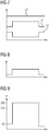
- FIG 5
- ein einzelnes Schaltelement und dessen Beschaltung und
- FIG 6 bis 16
- Zeitdiagramme.
- FIG. 1
- an inverter and a load
- FIG. 2
- a section of
FIG. 1 . - FIG. 3
- a flow chart,
- FIG. 4
- a time diagram,
- FIG. 5
- a single switching element and its wiring and
- FIGS. 6 to 16
- Time charts.
Gemäß
Über den Umrichter 1 wird eine Last 5 gespeist, also mit elektrischer Energie versorgt. Hierbei ist gewährleistet, dass das Anschalten der eingangsseitig des Umrichters 1 anstehenden Spannung U an die Last 5 nicht zu Stromstößen führt, sondern dass Stromanstiege und Stromabfälle geglättet werden. Beispielsweise können zu diesem Zweck zwischen dem Umrichter 1 und der Last 5 Drosseln 6 angeordnet sein. Es sind aber auch andere Ausgestaltungen möglich. Beispielsweise kann, wenn die Last 5 eine elektrische Maschine ist, die nötige Wirkung auch durch die Wicklungen der elektrischen Maschine als solche bewirkt werden.About the
Der Umrichter 1 weist gemäß
Der Umrichter 1 weist eine Steuereinrichtung 8 auf. Die Steuereinrichtung 8 ist mit einem Steuerprogramm 9 programmiert. Das Steuerprogramm 9 umfasst Maschinencode 10, der von der Steuereinrichtung 8 abarbeitbar ist. Die Abarbeitung des Maschinencodes 10 durch die Steuereinrichtung 8 bewirkt, dass die Steuereinrichtung 8 den Umrichter 1 gemäß einem Betriebsverfahren betreibt, das nachstehend näher erläutert wird.The
Gegebenenfalls steuert die Steuereinrichtung 8, wie in
Das erfindungsgemäße Betriebsverfahren wird in Verbindung mit einem einzelnen der Schaltelemente 7 erläutert. Es wird von der Steuereinrichtung 8 jedoch für alle Schaltelemente 7 ausgeführt.The operating method according to the invention is explained in connection with a single one of the
Die Steuereinrichtung 8 betreibt den Umrichter 1 alternativ in einem Normalbetrieb oder in einem Sonderbetrieb.
Im Normalbetrieb nimmt die Steuereinrichtung 8 in einem Schritt S1 einen Stromsollwert I* entgegen. In einem Schritt S2 ermittelt die Steuereinrichtung 8 sodann für die Schaltelemente 7 deren jeweilige Schaltzeitpunkte tij. Die Steuereinrichtung 8 ermittelt also - siehe
Die Schaltelemente 7 werden oftmals pulsweitenmoduliert gesteuert. Pulsweitenmodulation bedeutet, dass die Schaltzeitpunkte tij, derart ermittelt werden, dass in einem fest vorgegebenen Zeitraum - dem Kehrwert der Pulswiederholfrequenz - das entsprechende Schaltelement 7 während eines ersten Teils dieses Zeitraums durchgeschaltet wird und während eines zweiten Teils dieses Zeitraums gesperrt wird, wobei der erste und der zweite Teil zusammen den genannten Zeitraum ergeben. Wenn der erste Teil und der zweite Teil gleich groß sind, spricht man von einem duty cycle von 50 %. Wenn der erste Teil kleiner als der zweite Teil ist, liegt der duty cycle unter 50 %, im umgekehrten Fall über 50 %. Durch die Größe des duty cycle kann eingestellt werden, wie groß der Strom I ist. Die Steuereinrichtung 8 ermittelt somit im Ergebnis anhand des Stromsollwerts I* den erforderlichen duty cycle und bestimmt sodann anhand des duty cycle die Schaltzeitpunkte tij. Der Arbeitstakt kann mit dem Kehrwert der Pulswiederholfrequenz übereinstimmen. Alternativ kann der Arbeitstakt ein Vielfaches - insbesondere ein ganzzahliges Vielfaches des Kehrwerts der Pulswiederholfrequenz sein.The
Im Normalbetrieb nimmt die Steuereinrichtung 8 weiterhin in einem Schritt S3 Soll- oder Istgrößen entgegen. Beispielsweise kann die Steuereinrichtung 8 - siehe
In einem Schritt S5 prüft die Steuereinrichtung 8, ob die ermittelte Sperrschichttemperatur T unterhalb einer oberen Grenztemperatur TGO bleibt. Die obere Grenztemperatur TGO ist in Abhängigkeit von den verwendeten Schaltelementen 7 nach Bedarf bestimmt. Beispielsweise kann sie bei 150 °C liegen.In a step S5, the
Wenn und solange die ermittelte Sperrschichttemperatur T unterhalb der oberen Grenztemperatur TGO bleibt (= JA-Zweig des Schrittes S5), behält die Steuereinrichtung 8 den Normalbetrieb bei. Insbesondere geht die Steuereinrichtung 8 in diesem Fall zu einem Schritt S6 über. Im Schritt S6 steuert die Steuereinrichtung 8 das entsprechende Schaltelement 7 derart an, dass das entsprechende Schaltelement 7 zu den ermittelten Schaltzeitpunkten tij jeweils sperrt oder durchschaltet. Zu jedem Schaltzeitpunkt tij ändert das Schaltelement 7 also seinen Ansteuerzustand. Vom Schritt S6 aus geht die Steuereinrichtung 8 zum Schritt S1 zurück.If and as long as the determined junction temperature T remains below the upper limit temperature TGO (= YES branch of step S5), the
Zum Sperren des Schaltelements 7 schaltet die Steuereinrichtung 8 entsprechend der Darstellung in den
Die in
Die Ausgestaltung der Beschaltung von
Wenn die Steuereinrichtung 8 im Schritt S5 hingegen feststellt, dass die Sperrschichttemperatur T die obere Grenztemperatur TGO erreicht oder gar überschreitet(= NEIN-Zweig des Schrittes S5), geht die Steuereinrichtung 8 in den Sonderbetrieb über. Insbesondere geht die Steuereinrichtung 8 zu einem Schritt S7 oder zu einem Schritt S8 über. Die Schritte S7 und S8 sind in
Im Schritt S7 steuert die Steuereinrichtung 8 - analog zum Schritt S6 - das entsprechende Schaltelement 7 derart an, dass das entsprechende Schaltelement 7 zu den ermittelten Schaltzeitpunkten tij jeweils sperrt oder durchschaltet. Zu jedem Schaltzeitpunkt tij ändert das Schaltelement 7 also seinen Ansteuerzustand.In step S7, the control device 8 - analogous to step S6 - controls the
Zum Sperren des Schaltelements 7 schaltet die Steuereinrichtung 8 - analog zum Schritt S6 - entsprechend der Darstellung in den
Ersichtlich ist das dritte Potenzial P3 größer als das zweite Potenzial P2. Beispielsweise kann das dritte Potenzial P3 entsprechend der Darstellung in
Auch im Schritt S8 steuert die Steuereinrichtung 8 - erneut analog zum Schritt S6 - das entsprechende Schaltelement 7 derart an, dass das entsprechende Schaltelement 7 zu den ermittelten Schaltzeitpunkten tij jeweils sperrt oder durchschaltet. Zu jedem Schaltzeitpunkt tij ändert das Schaltelement 7 also seinen Ansteuerzustand. Zum Sperren des Schaltelements 7 schaltet die Steuereinrichtung 8 - erneut analog zum Schritt S6 - entsprechend der Darstellung in den
Gemäß der Darstellung in
Der Unterschied des Schrittes S8 zum Schritt S7 besteht also darin, dass die Steuereinrichtung 5 im Schritt S7 zum Durchschalten des jeweiligen Schaltelements 7 ausschließlich das dritte Potenzial P3 an die Steuerelektrode 11 des jeweiligen Schaltelements 7 anschaltet, während die Steuereinrichtung 5 im Schritt S8 das dritte Potenzial P3 nur temporär und im übrigen das zweite Potenzial P2 an die Steuerelektrode 11 des jeweiligen Schaltelements 7 anschaltet. Hierbei wird im Rahmen des Schrittes S8 zum Durchschalten des jeweiligen Schaltelements 7 zunächst zum jeweiligen Schaltzeitpunkt tij das zweite Potenzial P2 und erst danach das dritte Potenzial P3 an die Steuerelektrode 11 des jeweiligen Schaltelements 7 angeschaltet.The difference of step S8 to step S7 is thus that the
Der Zeitraum T1, während dessen im Rahmen des Schrittes S8 das zweite Potenzial P2 an die Steuerelektrode 11 des jeweiligen Schaltelements 7 angeschaltet wird, sollte kleiner als der Zeitraum T2 sein, während dessen im Rahmen des Schrittes S8 das dritte Potenzial P3 an die Steuerelektrode 11 des jeweiligen Schaltelements 7 angeschaltet wird. Wenn mit ![]()
![]()
Vom Schritt S7 bzw. S8 geht die Steuereinrichtung 8 zu einem Schritt S9 über. Im Schritt S9 prüft die Steuereinrichtung 8, ob die ermittelte Sperrschichttemperatur T unter eine untere Grenztemperatur TGU sinkt. Die untere Grenztemperatur TGU kann nach Bedarf bestimmt sein. Sie muss aber unter der oberen Grenztemperatur TGO liegen. Beispielsweise kann die untere Grenztemperatur TGU bei 130 °C liegen.From the step S7 or S8, the
Wenn und solange die ermittelte Sperrschichttemperatur T oberhalb der unteren Grenztemperatur TGU bleibt (= NEIN-Zweig des Schrittes S9), behält die Steuereinrichtung 8 den Sonderbetrieb bei. Insbesondere geht die Steuereinrichtung 8 in diesem Fall zu einem Schritt S10 über. Anderenfalls - also im JA-Zweig des Schrittes S9 - geht die Steuereinrichtung 8 zum Schritt S1 und damit in den Normalbetrieb über.If and as long as the determined junction temperature T remains above the lower limit temperature TGU (= NO branch of step S9), the
Im Schritt S10 nimmt die Steuereinrichtung 8 einen Stromsollwert I* entgegen. In einem nachfolgenden Schritt S11 ermittelt die Steuereinrichtung 8 für die Schaltelemente 7 deren jeweilige Schaltzeitpunkte tij. Sodann nimmt die Steuereinrichtung 8 in einem Schritt S12 Soll- oder Istgrößen entgegen und leitet daraus einem Schritt S13 die Sperrschichttemperatur T des jeweiligen Schaltelements 7 ab. Die Schritte S10 bis S13 korrespondieren inhaltlich mit den Schritten S1 bis S4 des Normalbetriebs. Der Unterschied besteht darin, dass im Schritt S13 der Ermittlung der Sperrschichttemperatur T gegebenenfalls anstelle des zweiten Potenzials P2 das dritte Potenzial P3 und die daraus resultierende Änderung der Durchlassspannung UD des jeweiligen Schaltelements 7 zugrunde gelegt wird.In step S10, the
In einem Schritt S14 prüft die Steuereinrichtung 8, ob die ermittelte Sperrschichttemperatur T die obere Grenztemperatur TGO erreicht oder gar überschreitet. Wenn dies der Fall ist (= JA-Zweig des Schrittes S14), geht die Steuereinrichtung 8 zu einem Schritt S15 über. Im Schritt S15 ermittelt die Steuereinrichtung 8 die Schaltzeitpunkte tij neu. Die Ermittlung des Schrittes S15 ist derart, dass der der Last 5 zugeführte Strom (genauer: im Regelfall die Phasenströme Ik) kleiner als der Stromsollwert I* ist. Im Falle einer Pulsweitenmodulation kann die Steuereinrichtung 8 die Schaltzeitpunkte tij beispielsweise auf Basis eines duty cycle unterhalb des duty cycle bestimmen, der zum Erreichen des Stromsollwerts I* erforderlich ist. Anderenfalls, also im NEIN-Zweig des Schrittes S14, überspringt die Steuereinrichtung 8 den Schritt S15. In diesem Fall geht die Steuereinrichtung 8 direkt zum Schritt S7 bzw. zum Schritt S8 über. Sie behält also in diesem Fall die im Schritt S11 ermittelten Schaltzeitpunkte tij unverändert bei.In a step S14, the
Die Darstellung des Schrittes S14 in
Es ist weiterhin möglich, dass die Steuereinrichtung 8 im Schritt S14 prüft, ob die Sperrschichttemperatur T im Sonderbetrieb zunächst abgesunken ist und erst danach, also nach dem Absinken, erneut die obere Grenztemperatur TGO erneut erreicht oder überschreitet. Auch in diesem Fall geht die Steuereinrichtung 8 vom Schritt S14 zum Schritt S15 über, gegebenenfalls sogar innerhalb der Wartezeit.It is also possible that the
Aus den obigen Ausführungen ist ersichtlich, dass die Steuereinrichtung 8 die Schritte S1 bis S15 zyklisch ausführt. In der Regel erfolgt eine getaktete Ausführung, dass also die Steuereinrichtung 8 mit einem Arbeitstakt jeweils einen der Schritte S1 bzw. S10 und die jeweils darauffolgenden Schritte S2 bis S6 bzw. S11 bis S15 sowie S7 bis S9 ausführt. Der Arbeitstakt liegt in der Regel im Mikrosekundenbereich, in manchen Fällen auch im Bereich weniger Millisekunden.From the above, it can be seen that the
Im Rahmen der obigen Ausführungen ist weiterhin vorgesehen, dass die Steuereinrichtung 8 in jedem Arbeitstakt vom Normalbetrieb in den Sonderbetrieb oder umgekehrt wechseln kann. Es ist jedoch möglich, bei einem Wechsel jeweils eine Sperre zu setzen, so dass nicht sofort wieder in den ursprünglichen Betrieb zurück gewechselt werden kann. Die Sperre kann beispielsweise für eine vorbestimmte Zeit - beispielsweise im einstelligen Sekundenbereich - oder für eine vorbestimmte Anzahl von Arbeitstakten gesetzt sein.In the context of the above statements, it is further provided that the
Im Rahmen der bisherigen Erläuterungen - insbesondere der Ausgestaltung gemäß
Die erfindungsgemäße Vorgehensweise wird kurz nochmals in Verbindung mit den
Gemäß den
Zusammengefasst betrifft die vorliegende Erfindung somit folgenden Sachverhalt:
Eine Steuereinrichtung 8 eines Umrichters 1 nimmt getaktet jeweils einen Stromsollwert I* entgegen und ermittelt Schaltzeitpunkte tij für Schaltelemente 7 des Umrichters 1, so dass der Umrichter 1 einer Last 5 einen mit dem Stromsollwert I* korrespondierenden Strom I zuführt. Die Steuereinrichtung 8 nimmt Soll- oder Istgrößen Ik - entgegen und leitet daraus eine Sperrschichttemperatur T der Schaltelemente 7 ab. Die Steuereinrichtung 8 bleibt in einem Normalbetrieb, solange die Sperrschichttemperatur T unterhalb einer Grenztemperatur TGO bleibt. Anderenfalls wechselt sie in den Sonderbetrieb. Die Steuereinrichtung 8 bleibt im Sonderbetrieb, solange die Sperrschichttemperatur T oberhalb einer unteren Grenztemperatur TGO bleibt. Anderenfalls wechselt sie in den Normalbetrieb. Wenn die Sperrschichttemperatur T im Sonderbetrieb die obere Grenztemperatur TGO für längere Zeit erreicht oder überschreitet und/oder nach einem Absinken erneut erreicht oder überschreitet, modifiziert die Steuereinrichtung 8 die Schaltzeitpunkte tij, so dass der der Last 5 zugeführte Strom I kleiner als der Stromsollwert I* ist. In beiden Modi sperrt die Steuereinrichtung 8 die Schaltelemente 7 zu den ermittelten Schaltzeitpunkten tij jeweils bzw. schaltet sie durch. Zum Sperren schaltet die Steuereinrichtung 8 in beiden Modi ein erstes Potenzial P1 an eine Steuerelektrode 11 des jeweiligen Schaltelements 7 an, zum Durchschalten im Normalbetrieb ein zweites Potenzial P2 und im Sonderbetrieb zumindest temporär ein drittes Potenzial P3 und im übrigen das zweite Potenzial P2. Die Differenz des dritten Potenzials P3 zum ersten Potenzial P1 ist größer als die Differenz des zweiten Potenzials P2 zum ersten Potenzial P1.In summary, the present invention thus relates to the following facts:
A
Die vorliegende Erfindung weist viele Vorteile auf. Insbesondere können die in den Schaltelementen 7 auftretenden Verluste temporär reduziert werden und dadurch temporär eine höhere Ausgangsleistung des Umrichters 1 erreicht werden. Dadurch ist ein Betrieb mit erhöhtem Strombedarf für längere Zeit möglich. Dennoch wird die Lebensdauer des Umrichters 1 nicht oder nur in vernachlässigbarem Umfang reduziert.The present invention has many advantages. In particular, the losses occurring in the
Obwohl die Erfindung im Detail durch das bevorzugte Ausführungsbeispiel näher illustriert und beschrieben wurde, so ist die Erfindung nicht durch die offenbarten Beispiele eingeschränkt und andere Variationen können vom Fachmann hieraus abgeleitet werden, ohne den Schutzumfang der Erfindung zu verlassen.Although the invention has been further illustrated and described in detail by the preferred embodiment, the invention is not limited by the disclosed examples, and other variations can be derived therefrom by those skilled in the art without departing from the scope of the invention.
Claims (11)
dadurch gekennzeichnet,
dass die Steuereinrichtung (8) im Sonderbetrieb zum Durchschalten des jeweiligen Schaltelements (7) ausschließlich das dritte Potenzial (P3) an die Steuerelektrode (11) des jeweiligen Schaltelements (7) anschaltet.Operating method according to claim 1,
characterized,
in that the control device (8) exclusively switches on the third potential (P3) to the control electrode (11) of the respective switching element (7) in the special mode for switching through the respective switching element (7).
dadurch gekennzeichnet,
dass die Steuereinrichtung (8) im Sonderbetrieb zum Durchschalten des jeweiligen Schaltelements (7) zunächst zum jeweiligen Schaltzeitpunkt (tij) das zweite Potenzial (P2) und erst danach das dritte Potenzial (P3) an die Steuerelektrode (11) des jeweiligen Schaltelements (7) anschaltet.Operating method according to claim 1,
characterized,
that the control device (8) in the special mode for switching through the respective switching element (7) first to the respective switching time (tij) the second potential (P2) and only then the third potential (P3) to the control electrode (11) of the respective switching element (7) turns.
dadurch gekennzeichnet,
dass, bezogen auf den jeweiligen Zeitraum (T1+T2), zu dem das jeweilige Schaltelement (7) durchgeschaltet ist, der Anteil, zu dem die Steuereinrichtung (8) das dritte Potenzial (P3) an die Steuerelektrode (11) des jeweiligen Schaltelements (7) anschaltet, größer als der Anteil ist, zu dem die Steuereinrichtung (8) das zweite Potenzial (P2) an die Steuerelektrode (11) des jeweiligen Schaltelements (7) anschaltet.Operating method according to claim 3,
characterized,
that , based on the respective period (T1 + T2), to which the respective switching element (7) is turned on, the proportion, too wherein the control device (8) switches on the third potential (P3) to the control electrode (11) of the respective switching element (7) is greater than the proportion to which the control device (8) applies the second potential (P2) to the control electrode (11 ) of the respective switching element (7).
dadurch gekennzeichnet,
dass, bezogen auf das erste Potenzial (P1), das dritte Potenzial (P3) um mindestens 10 % größer als das zweite Potenzial (P2) ist.Operating method according to one of the above claims,
characterized,
that , based on the first potential (P1), the third potential (P3) is at least 10% greater than the second potential (P2).
dadurch gekennzeichnet,
dass, bezogen auf das erste Potenzial (P1), das dritte Potenzial (P3) um maximal 100 % größer als das zweite Potenzial (P2) ist.Operating method according to one of the above claims,
characterized,
that , based on the first potential (P1), the third potential (P3) is at most 100% greater than the second potential (P2).
dadurch gekennzeichnet,
dass das dritte Potenzial (P3) um 3 V bis 10 V größer als das zweite Potenzial (P2) ist.Operating method according to one of the above claims,
characterized,
that the third potential (P3) to 10 V is greater than the second potential (P2) to 3V.
dadurch gekennzeichnet,
dass das zweite Potenzial (P2) um 8 V bis 30 V größer als das erste Potenzial (P1) ist.Operating method according to one of the above claims,
characterized,
that the second potential (P2) is greater than the first potential (P1) at 8 V to 30 V.
Priority Applications (1)
| Application Number | Priority Date | Filing Date | Title |
|---|---|---|---|
| EP18174871.6A EP3576270A1 (en) | 2018-05-29 | 2018-05-29 | Inverter operation with increased gate driving voltage at high junction temperatures |
Applications Claiming Priority (1)
| Application Number | Priority Date | Filing Date | Title |
|---|---|---|---|
| EP18174871.6A EP3576270A1 (en) | 2018-05-29 | 2018-05-29 | Inverter operation with increased gate driving voltage at high junction temperatures |
Publications (1)
| Publication Number | Publication Date |
|---|---|
| EP3576270A1 true EP3576270A1 (en) | 2019-12-04 |
Family
ID=62492431
Family Applications (1)
| Application Number | Title | Priority Date | Filing Date |
|---|---|---|---|
| EP18174871.6A Withdrawn EP3576270A1 (en) | 2018-05-29 | 2018-05-29 | Inverter operation with increased gate driving voltage at high junction temperatures |
Country Status (1)
| Country | Link |
|---|---|
| EP (1) | EP3576270A1 (en) |
Citations (5)
| Publication number | Priority date | Publication date | Assignee | Title |
|---|---|---|---|---|
| DE102007004006A1 (en) * | 2006-03-23 | 2007-10-11 | Hitachi, Ltd. | Driver circuit for semiconductor switching element with a wide gap |
| DE112014001238T5 (en) * | 2013-09-25 | 2016-01-14 | Fuji Electric Co., Ltd. | Insulated gate semiconductor device |
| DE102016201923A1 (en) * | 2016-02-09 | 2017-08-10 | Siemens Aktiengesellschaft | Robust current limit for an electric drive |
| EP3206286A1 (en) * | 2016-02-10 | 2017-08-16 | GE Energy Power Conversion Technology Ltd | Gatespannungsübersteuerung für das schalten von stossströmen in igbt schaltern |
| EP3280052A1 (en) * | 2016-08-01 | 2018-02-07 | GE Energy Power Conversion Technology Ltd | Method and device for driving a voltage-controlled turn-off power semiconductor switch |
-
2018
- 2018-05-29 EP EP18174871.6A patent/EP3576270A1/en not_active Withdrawn
Patent Citations (5)
| Publication number | Priority date | Publication date | Assignee | Title |
|---|---|---|---|---|
| DE102007004006A1 (en) * | 2006-03-23 | 2007-10-11 | Hitachi, Ltd. | Driver circuit for semiconductor switching element with a wide gap |
| DE112014001238T5 (en) * | 2013-09-25 | 2016-01-14 | Fuji Electric Co., Ltd. | Insulated gate semiconductor device |
| DE102016201923A1 (en) * | 2016-02-09 | 2017-08-10 | Siemens Aktiengesellschaft | Robust current limit for an electric drive |
| EP3206286A1 (en) * | 2016-02-10 | 2017-08-16 | GE Energy Power Conversion Technology Ltd | Gatespannungsübersteuerung für das schalten von stossströmen in igbt schaltern |
| EP3280052A1 (en) * | 2016-08-01 | 2018-02-07 | GE Energy Power Conversion Technology Ltd | Method and device for driving a voltage-controlled turn-off power semiconductor switch |
Similar Documents
| Publication | Publication Date | Title |
|---|---|---|
| EP0630853B1 (en) | Hydraulic lifting equipment for battery-propelled handling trucks or the like | |
| EP3280052B1 (en) | Method and device for driving a voltage-controlled turn-off power semiconductor switch | |
| EP3022836B1 (en) | Overvoltage protection for active rectifiers in the event of load shedding | |
| DE102011002674B4 (en) | Circuit and method for de-exciting an excitation coil | |
| EP0291803A2 (en) | Drive pulse circuitry for semiconductor switches | |
| DE112017005404T5 (en) | DC-DC converter | |
| EP3915127B1 (en) | Direct current circuit breaker device | |
| EP2899879B1 (en) | Method for operation and device for controlling a rotating brushless electrical machine | |
| DE102017204091A1 (en) | Switching device for switching an electrical excitation current for an electric machine with a rotor | |
| DE10236872B4 (en) | Circuit arrangement for controllable power supply, in particular circuit arrangement for dimming of light emitting diode arrangements | |
| EP3576270A1 (en) | Inverter operation with increased gate driving voltage at high junction temperatures | |
| EP1063772A1 (en) | Half-bridge driver circuit | |
| DE102018213130A1 (en) | Electrical vehicle electrical system and motor vehicle with such an electrical system | |
| EP3695500B1 (en) | Intermediate circuit converter with targeted coupling with at least one other intermediate circuit converter | |
| DE102004042256A1 (en) | Direct voltage link circuit e.g. for printing machine, has DC link voltage dropped across series-circuit of ohmic resistor and DC link capacitor | |
| DE102008040724A1 (en) | Electrical consumer e.g. starter motor, starting current limiting method for internal combustion engine of motor vehicle, involves operating switch in clocked manner to limit starting current of electrical consumer | |
| EP2182625A1 (en) | Method for operating a frequency converter, computer program to implement such a method and data medium and computer system, especially frequency converter on which such a computer program is saved or loaded | |
| EP0988482A1 (en) | Electromagnetic actuator | |
| DE2731501B2 (en) | Control arrangement for a direct current motor operated with series-circuit-shunt changeover | |
| DE102016011335A1 (en) | Switching arrangement for a battery arrangement of a motor vehicle, and method for operating a switching arrangement for a battery assembly of a motor vehicle | |
| DE102020204338B4 (en) | Triggering device with intelligent control for actuating a switching device and method for operating such a triggering device | |
| DE3928281A1 (en) | ARRANGEMENT FOR GENERATING CURRENT PULSES IN A SPECIFIC SHAPE IN AN INDUCTIVE CONSUMER | |
| DE102022203730A1 (en) | Device and method for providing a control signal for pulse width modulation, power converter and electrical drive system | |
| DE102009043553A1 (en) | Switching arrangement for phase exact switching of alternating voltage, has relay with switching contact lying in load current cycle, where load current cycle has pair of connections | |
| DE10115326B4 (en) | Method for controlling a resonant circuit inverter, resonant circuit inverter and controller |
Legal Events
| Date | Code | Title | Description |
|---|---|---|---|
| PUAI | Public reference made under article 153(3) epc to a published international application that has entered the european phase |
Free format text: ORIGINAL CODE: 0009012 |
|
| AK | Designated contracting states |
Kind code of ref document: A1 Designated state(s): AL AT BE BG CH CY CZ DE DK EE ES FI FR GB GR HR HU IE IS IT LI LT LU LV MC MK MT NL NO PL PT RO RS SE SI SK SM TR |
|
| AX | Request for extension of the european patent |
Extension state: BA ME |
|
| STAA | Information on the status of an ep patent application or granted ep patent |
Free format text: STATUS: THE APPLICATION IS DEEMED TO BE WITHDRAWN |
|
| 18D | Application deemed to be withdrawn |
Effective date: 20200605 |