EP3576266A1 - Rotary electric machine - Google Patents
Rotary electric machine Download PDFInfo
- Publication number
- EP3576266A1 EP3576266A1 EP19177038.7A EP19177038A EP3576266A1 EP 3576266 A1 EP3576266 A1 EP 3576266A1 EP 19177038 A EP19177038 A EP 19177038A EP 3576266 A1 EP3576266 A1 EP 3576266A1
- Authority
- EP
- European Patent Office
- Prior art keywords
- rotor
- magnetic pole
- electric machine
- rotary electric
- section
- Prior art date
- Legal status (The legal status is an assumption and is not a legal conclusion. Google has not performed a legal analysis and makes no representation as to the accuracy of the status listed.)
- Withdrawn
Links
Images


Classifications
-
- H—ELECTRICITY
- H02—GENERATION; CONVERSION OR DISTRIBUTION OF ELECTRIC POWER
- H02K—DYNAMO-ELECTRIC MACHINES
- H02K19/00—Synchronous motors or generators
- H02K19/02—Synchronous motors
- H02K19/10—Synchronous motors for multi-phase current
- H02K19/103—Motors having windings on the stator and a variable reluctance soft-iron rotor without windings
-
- F—MECHANICAL ENGINEERING; LIGHTING; HEATING; WEAPONS; BLASTING
- F02—COMBUSTION ENGINES; HOT-GAS OR COMBUSTION-PRODUCT ENGINE PLANTS
- F02N—STARTING OF COMBUSTION ENGINES; STARTING AIDS FOR SUCH ENGINES, NOT OTHERWISE PROVIDED FOR
- F02N11/00—Starting of engines by means of electric motors
- F02N11/04—Starting of engines by means of electric motors the motors being associated with current generators
-
- F—MECHANICAL ENGINEERING; LIGHTING; HEATING; WEAPONS; BLASTING
- F02—COMBUSTION ENGINES; HOT-GAS OR COMBUSTION-PRODUCT ENGINE PLANTS
- F02N—STARTING OF COMBUSTION ENGINES; STARTING AIDS FOR SUCH ENGINES, NOT OTHERWISE PROVIDED FOR
- F02N15/00—Other power-operated starting apparatus; Component parts, details, or accessories, not provided for in, or of interest apart from groups F02N5/00 - F02N13/00
- F02N15/006—Assembling or mounting of starting devices
-
- H—ELECTRICITY
- H02—GENERATION; CONVERSION OR DISTRIBUTION OF ELECTRIC POWER
- H02K—DYNAMO-ELECTRIC MACHINES
- H02K1/00—Details of the magnetic circuit
- H02K1/06—Details of the magnetic circuit characterised by the shape, form or construction
- H02K1/12—Stationary parts of the magnetic circuit
-
- H—ELECTRICITY
- H02—GENERATION; CONVERSION OR DISTRIBUTION OF ELECTRIC POWER
- H02K—DYNAMO-ELECTRIC MACHINES
- H02K1/00—Details of the magnetic circuit
- H02K1/06—Details of the magnetic circuit characterised by the shape, form or construction
- H02K1/22—Rotating parts of the magnetic circuit
-
- H—ELECTRICITY
- H02—GENERATION; CONVERSION OR DISTRIBUTION OF ELECTRIC POWER
- H02K—DYNAMO-ELECTRIC MACHINES
- H02K1/00—Details of the magnetic circuit
- H02K1/06—Details of the magnetic circuit characterised by the shape, form or construction
- H02K1/22—Rotating parts of the magnetic circuit
- H02K1/24—Rotor cores with salient poles ; Variable reluctance rotors
-
- H—ELECTRICITY
- H02—GENERATION; CONVERSION OR DISTRIBUTION OF ELECTRIC POWER
- H02K—DYNAMO-ELECTRIC MACHINES
- H02K19/00—Synchronous motors or generators
- H02K19/16—Synchronous generators
- H02K19/22—Synchronous generators having windings each turn of which co-operates alternately with poles of opposite polarity, e.g. heteropolar generators
- H02K19/24—Synchronous generators having windings each turn of which co-operates alternately with poles of opposite polarity, e.g. heteropolar generators with variable-reluctance soft-iron rotors without winding
-
- H—ELECTRICITY
- H02—GENERATION; CONVERSION OR DISTRIBUTION OF ELECTRIC POWER
- H02K—DYNAMO-ELECTRIC MACHINES
- H02K21/00—Synchronous motors having permanent magnets; Synchronous generators having permanent magnets
- H02K21/02—Details
- H02K21/04—Windings on magnets for additional excitation ; Windings and magnets for additional excitation
- H02K21/046—Windings on magnets for additional excitation ; Windings and magnets for additional excitation with rotating permanent magnets and stationary field winding
- H02K21/048—Rotor of the claw pole type
-
- H—ELECTRICITY
- H02—GENERATION; CONVERSION OR DISTRIBUTION OF ELECTRIC POWER
- H02K—DYNAMO-ELECTRIC MACHINES
- H02K21/00—Synchronous motors having permanent magnets; Synchronous generators having permanent magnets
- H02K21/12—Synchronous motors having permanent magnets; Synchronous generators having permanent magnets with stationary armatures and rotating magnets
- H02K21/14—Synchronous motors having permanent magnets; Synchronous generators having permanent magnets with stationary armatures and rotating magnets with magnets rotating within the armatures
-
- H—ELECTRICITY
- H02—GENERATION; CONVERSION OR DISTRIBUTION OF ELECTRIC POWER
- H02K—DYNAMO-ELECTRIC MACHINES
- H02K21/00—Synchronous motors having permanent magnets; Synchronous generators having permanent magnets
- H02K21/38—Synchronous motors having permanent magnets; Synchronous generators having permanent magnets with rotating flux distributors, and armatures and magnets both stationary
- H02K21/44—Synchronous motors having permanent magnets; Synchronous generators having permanent magnets with rotating flux distributors, and armatures and magnets both stationary with armature windings wound upon the magnets
-
- H—ELECTRICITY
- H02—GENERATION; CONVERSION OR DISTRIBUTION OF ELECTRIC POWER
- H02K—DYNAMO-ELECTRIC MACHINES
- H02K3/00—Details of windings
- H02K3/04—Windings characterised by the conductor shape, form or construction, e.g. with bar conductors
- H02K3/12—Windings characterised by the conductor shape, form or construction, e.g. with bar conductors arranged in slots
-
- H—ELECTRICITY
- H02—GENERATION; CONVERSION OR DISTRIBUTION OF ELECTRIC POWER
- H02K—DYNAMO-ELECTRIC MACHINES
- H02K5/00—Casings; Enclosures; Supports
- H02K5/04—Casings or enclosures characterised by the shape, form or construction thereof
- H02K5/16—Means for supporting bearings, e.g. insulating supports or means for fitting bearings in the bearing-shields
- H02K5/173—Means for supporting bearings, e.g. insulating supports or means for fitting bearings in the bearing-shields using bearings with rolling contact, e.g. ball bearings
-
- H—ELECTRICITY
- H02—GENERATION; CONVERSION OR DISTRIBUTION OF ELECTRIC POWER
- H02K—DYNAMO-ELECTRIC MACHINES
- H02K2201/00—Specific aspects not provided for in the other groups of this subclass relating to the magnetic circuits
- H02K2201/03—Machines characterised by aspects of the air-gap between rotor and stator
Definitions
- the present invention relates to a brushless winding field type rotary electric machine disposed around the outer periphery of a rotary member.
- a rotary electric machine for supplying a magnetic flux from a field coil 102 that is stationary with respect to a rotor 101 is proposed.
- a stator 103 is disposed on the radial outside of a rotor 101.
- a power supply device required for magnetizing the rotor 101 that is, a slip ring using the so-called brushes, can be abolished.
- This type of rotary electric machine is a brushless winding field type rotary electric machine 110.
- a first air gap 111 is provided between the stator 103 and the rotor 101, and a second air gap 112 is provided between a field coil 102 and the rotor 101. Both the air gaps extend along the axial direction of a rotation shaft 107.
- Patent Document 2 proposes a structure in which a rotary electric machine is disposed around the outer periphery of a starting device.
- the rotary electric machine having this structure is connected to an engine, whereby the rotary electric machine can start the engine and can function as a generator during vehicle traveling. Consequently, the starter and the alternator required for conventional vehicles can be abolished.
- An object of the present invention is thus to provide a rotary electric machine capable of enhancing the degree of freedom in design and improving the output performance of the rotary electric machine by solving the above-mentioned problems.
- the present invention features a brushless winding field type rotary electric machine positioned between a rotary member and a stationary case, being equipped with:
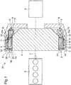
- the rotary electric machine is a brushless winding field type rotary electric machine 10 that is disposed between an engine 8 and a transmission 9 along a rotation shaft 7 and positioned between a stationary case 5 containing a starting device 4 and the starting device 4.
- This rotary electric machine 10 is equipped with at least a stator 3, a field coil 2 and a rotor 1.
- the stator 3 is unrotatably fixed to and held in the stationary case 5, is constituted of a cylindrical member having a plurality of slots in which an AC coil 14 is wound, is provided with the AC coil 14 inside, and generates a rotating magnetic field by the AC current flowing in the AC coil 14.
- the field coil 2 is disposed while being shifted from the stator 3 and the rotor 1 along the rotation shaft 7, is fixed to and held in the stationary case 5 on the transmission 9 side of the stator 3, and is excited by a DC current.
- a field core 6 has the field coil 2 inside.
- the field coil 2 may be disposed while being shifted from the stator 3 and the rotor 1 along the rotation shaft 7 to the engine 8 side of the stator 3 via a second air gap 12, instead of the transmission 9 side of the stator 3, as shown in the region 89 indicated by a dashed line in Fig. 1 .
- the rotor 1 is disposed so as to be fixed to the outer periphery of the starting device 4.
- the outer peripheral face of the rotor 1 is opposed to the inner peripheral face of the stator 3, and the end face on the transmission 9 side of the rotor 1 is opposed to the end face on the engine 8 side of the field coil 2.
- the rotor 1 is held so as to be rotatable with respect to the stator 3 and the field coil 2 around the rotation shaft 7.
- a first air gap 11 is formed between the stator 3 and the rotor 1, thereby delivering a magnetic flux between the stator 3 and the rotor 1.
- the first air gap 11 is a gap extending along the axial direction of the rotation shaft 7 between the inner peripheral face of the stator 3 and the outer peripheral face of the rotor 1.
- the second air gap 12 is formed between the field core 6 and the rotor 1, thereby delivering the magnetic flux between the field coil 2 and the rotor 1. More specifically, the second air gap 12 has an air gap 12A formed between the field core 6 and the second magnet pole 22 of the rotor 1 and an air gap 12B formed between the field core 6 and the first magnetic pole 21 of the rotor 1. In other words, the air gap 12A is formed between the field core 6 and the radially inner portion of the portion on the field core 6 side of the rotor 1. The air gap 12B is formed between the field core 6 and the radially outer portion 210 of the portion on the field core 6 side of the rotor 1. The air gap 12A is formed so as to be perpendicular to the axial direction of the rotation shaft 7.
- the air gap 12B is formed so as to be inclined with respect to the axial direction of the rotation shaft 7. More specifically, the air gap 12B is composed of a first vertical section 121 being perpendicular to the axial direction of the rotation shaft 7, an inclined section 122 inclined at an inclination angle ⁇ with respect to the axial direction of the rotation shaft 7, and a second vertical section 123 being perpendicular to the axial direction of the rotation shaft 7.
- the first vertical section 121, the inclined section 122 and the second vertical section 123 are formed so as to be continuous.
- the inclined section 122 is inclined gradually from the side of the engine 8 to the side of the transmission 9 as the inclined section 122 extends from the inside to the outside in the radial direction.
- the radially outer portion 210 on the field core 6 side of the rotor 1 is positioned on the radially outer side than the field core 6.
- the inclination angle ⁇ is preferably in a range of 10 to 25 degrees.
- the gap widths of the first vertical section 121, the inclined section 122 and the second vertical section 123 are nearly the same.
- the radially outside portion of the portion on the field core 6 side of the rotor 1 has a beak shape in a vertical cross section protruding toward the field core 6, and the portion on the rotor 1 side of the field core 6 has such a convex shape so as to get into the beak of the rotor 1.
- the rotor 1 is configured by combining the first magnetic pole 21, the second magnet pole 22 and a magnetic pole holding member 23.
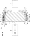
- the sectional view taken on the line A-A in Fig. 4 corresponds to a sectional view showing the rotary electric machine 10, the starting device 4, etc. shown at the center of Fig. 1 .
- the first magnetic pole 21 is made from a soft magnetic material, such as iron, and has a plurality of pawl sections 21b having, for example, a rectangular thin-plate shape, and protruding from a first annular section 21a in the axial direction of the rotation shaft 7.
- the pawl sections 21b are disposed at constant intervals, for example, at equal intervals, in the circumferential direction, and the lengths of all the pawl sections 21b in the axial direction of the rotation shaft 7 are the same.
- the outer peripheral faces of the respective pawl sections 21b are disposed along the outer peripheral face of the first annular section 21a. Even in the case that the first magnetic pole 21 is combined with the second magnet pole 22, the pawl sections 21b do not make contact with the second magnet pole 22, and a radial clearance 16 is formed in the radial direction.
- the second magnetic pole 22 is made from a soft magnetic material, such as iron, and is disposed so that the radial clearance 16 ( Fig. 1 ) is provided on the inside of the first annular section 21a.
- the second magnetic pole 22 has a plurality of convex sections 22b having, for example, a rectangular plate shape, the convex sections radially protruding and being disposed while having circumferential clearances 17 in the circumferential direction on the outer peripheral face of a second annular section 22a that is disposed so as to be partially overlapped with the first annular section 21a.
- the convex sections 22b are also disposed at constant intervals, for example, at equal intervals, in the circumferential direction, and the radial heights of all the convex sections 22b are the same.
- the lengths of all the convex sections 22b in the axial direction of the rotation shaft 7 are the same and shorter than the length of the pawl section 21b.
- the outer peripheral faces of the respective convex sections 22b are disposed on a circle that has the same center as the center of the rotation axis of the rotor 1.
- Each convex section 22b extends to the edge on the engine 8 side of the second annular section 22a and is formed into a second tip end engagement section 22c.
- each convex section 22b does not extend to the edge on the transmission 9 side of the second annular section 22a, and an annular fitting section 22d being narrow in width and not having the convex sections 22b is formed.
- the first magnetic pole 21 and the second magnet pole 22 are assembled by moving the first magnetic pole 21 to the second magnet pole 22 in the axial direction and by inserting each pawl section 21b of the first magnetic pole 21 into the intermediate section of the circumferential clearance 17 between the adjacent convex sections 22b so that the pawl sections 21b and the convex sections 22b are disposed alternately in the circumferential direction.
- the assembling is performed so that the first annular section 21a of the first magnetic pole 21 can be disposed on the outside of the fitting section 22d while the radial clearance 16 is provided therebetween.
- an axial clearance 19 is provided between each convex section 22b and the first annular section 21a
- the circumferential clearance 17 is provided in the circumferential direction between each pawl section 21b and each convex section 22b of the second magnet pole 22, and the radial clearance 16 is also provided in the radial direction.
- the magnetic pole holding member 23 is further provided in order to fix the first magnetic pole 21 and the second magnet pole 22 in this state.
- the magnetic pole holding member 23 is an annular member made from a nonmagnetic material, such as aluminum or austenitic stainless steel, and has a fitting section 23a into which the first tip end engagement sections 21c of the pawl sections 21b of the first magnetic pole 21 are fitted and fixed and the second tip end engagement sections 22c of the convex sections 22b of the second magnet pole 22 are fitted and fixed, for example, on the outer peripheral side.
- the first tip end engagement sections 21c and the second tip end engagement sections 22c are fitted into the fitting section 23a and then fixed, for example, by bolt fastening, shrink fitting or brazing, whereby the first magnetic pole 21 and the second magnet pole 22 are fixed and held by the magnetic pole holding member 23 in a noncontact state.
- the first tip end engagement section 21c of the pawl section 21b of the first magnetic pole 21 and the second tip end engagement section 22c of the convex section 22b of the second magnet pole 22 are each, as a specific example, formed into a step section, and the step section is fitted into the engagement concave section of the fitting section 23a, thereby being held so as to be fixed in the radial direction.
- the second tip end engagement section 22c is disposed, as an example, at the tip end of the convex section 22b, the second tip end engagement section 22c may be disposed at the tip end of the second annular section 22a.
- a field coil magnetic flux 15 is generated.
- the field coil magnetic flux 15 is formed by starting from the field core 6 and returning to the field core 6 via the second air gap 12 (the air gap 12B), the first magnetic pole 21 of the rotor 1, the first air gap 11, the stator 3, the first air gap 11, the second magnetic pole 22 of the rotor 1, and the second air gap 12 (the air gap 12A) .
- the field coil magnetic flux 15 is generated, whereby the first magnetic pole 21 and the second magnetic pole 22 are magnetized to, for example, an N pole and an S pole, respectively.
- the stator 3 is magnetized by driving an inverter, not shown, and by applying a three-phase AC current to the stator 3, and a current is applied to the field coil 2.
- the first magnetic pole 21 and the second magnetic pole 22 of the rotor 1 are excited by applying the current to the field coil 2.
- the rotor 1 starts rotating with respect to the stator 3, and an electromotive force having an induction voltage is generated in the stator 3.
- the induction voltage increases as the rotation speed of the rotor 1 increases.
- the rotation speed reaches an initial-explosion rotation speed that is lower than the idling rotation speed corresponding to the idling of the engine 8 and the starting of the engine 8 is completed.
- the driving of the inverter is stopped.
- the operation mode of the rotary electric machine 10 is automatically shifted to a power generation mode in which the rotary electric machine 10 operates as a generator to perform a power generation function so that the induction voltage is maintained at a predetermined induction voltage (required voltage).
- the exciting current is adjusted so that the induction voltage becomes constant at the predetermined induction voltage.
- the exciting current is adjusted so that the magnetization force of the rotor decreases as the rotation speed increases, thereby making the induction voltage constant.
- the lead angle of the three-phase AC current is adjusted by the inverter so that the induction voltage becomes constant at the predetermined induction voltage.
- the adjustment may be made by combining the above-mentioned two methods. With this control, when the rotor 1 is rotated, the rotary electric machine 10 functions as a generator.
- the rotary electric machine 10 can start the engine and can function as a generator during vehicle traveling by connecting the rotary electric machine 10 to the engine 8.
- permanent magnets 27 are disposed inside the rotor 1 in the configuration according to the first embodiment.
- the permanent magnets 27 having, for example, a rectangular plate shape, are provided at the same circumferential positions as those of the respective pawl sections 21b of the first magnetic pole 21 and on the inner diameter sides of the respective pawl sections 21b of the first magnetic pole 21 and on the outer diameter side of the second annular section 22a of the second magnetic pole 22 so as to be held between the inner peripheral faces of the respective pawl sections 21b and the outer peripheral face of the second annular section 22a.
- the magnetic flux 28 of the permanent magnet 27 is formed between each pawl section 21b of the first magnetic pole 21 and each convex section 22b of the second magnet pole 22.
- the permanent magnet 27 is a magnet mainly made from neodymium or a magnet mainly made from ferrite. More specifically, various kinds of permanent magnets, such as SmCo magnets, AlNiCo magnets or neodymium bonded magnets, can be used as the permanent magnets 27. Each permanent magnet 27 is disposed on the whole inner face of each pawl section 21b or part thereof.
- the magnetic flux 28 of the permanent magnet 27 can be used in addition to the magnetic flux generated in the rotor 1 by the field coil 2, whereby the output performance of the rotary electric machine can be improved. Furthermore, since the permanent magnets 27 are pressed and held with the pawl sections 21b, the strength of the permanent magnets 27 against a centrifugal force can be reinforced, and the deformation of the permanent magnets 27 due to the centrifugal force can be prevented, whereby the centrifugal strength at high speed rotation can be improved.
- the present invention is useful as a rotary electric machine for wide and general use in driving and power generating apparatuses, thereby having a high industrial applicability.
Landscapes
- Engineering & Computer Science (AREA)
- Power Engineering (AREA)
- Chemical & Material Sciences (AREA)
- Combustion & Propulsion (AREA)
- Mechanical Engineering (AREA)
- General Engineering & Computer Science (AREA)
- Synchronous Machinery (AREA)
- Iron Core Of Rotating Electric Machines (AREA)
Abstract
Description
- The present invention relates to a brushless winding field type rotary electric machine disposed around the outer periphery of a rotary member.
- As shown in
Fig. 8 (b) showing a conventional example (refer to Patent Document 1), a rotary electric machine for supplying a magnetic flux from afield coil 102 that is stationary with respect to arotor 101 is proposed. Astator 103 is disposed on the radial outside of arotor 101. With this structure, a power supply device required for magnetizing therotor 101, that is, a slip ring using the so-called brushes, can be abolished. This type of rotary electric machine is a brushless winding field type rotaryelectric machine 110. Afirst air gap 111 is provided between thestator 103 and therotor 101, and asecond air gap 112 is provided between afield coil 102 and therotor 101. Both the air gaps extend along the axial direction of arotation shaft 107. - Furthermore,
Patent Document 2 proposes a structure in which a rotary electric machine is disposed around the outer periphery of a starting device. The rotary electric machine having this structure is connected to an engine, whereby the rotary electric machine can start the engine and can function as a generator during vehicle traveling. Consequently, the starter and the alternator required for conventional vehicles can be abolished. -
- [Patent Document 1]
JP 3445492 B1 - [Patent Document 2]
JP 2010-516558 T - In the case that an attempt is made to dispose the brushless winding field type rotary
electric machine 110 around the outer periphery of astarting device 104 as shown inFig. 8(b) by combining the structures disclosed in these two Patent Documents, in the combination of the structures disclosed in the two Patent Documents, the three members, i.e., thestator 103 to be fixed to astationary case 105, therotor 101, and thefield coil 102 are disposed coaxially and on different diameters with therotation shaft 107 in a narrow space between the inner peripheral side of thestationary case 105 and the outer peripheral side of thestarting device 104. Hence, there is a strict restriction on the volume to be occupied by the rotaryelectric machine 110, whereby there are problems that the degree of freedom in design is limited and the output performance of the rotaryelectric machine 110 is limited. - An object of the present invention is thus to provide a rotary electric machine capable of enhancing the degree of freedom in design and improving the output performance of the rotary electric machine by solving the above-mentioned problems.
- The present invention features a brushless winding field type rotary electric machine positioned between a rotary member and a stationary case, being equipped with:
- a stator held in the stationary case and internally equipped with an AC coil for generating a rotating magnetic field by an AC current,
- a field core held in the stationary case and internally equipped with a field coil excited by a DC current,
- a rotor disposed around the outer periphery of the rotary member and held so as to be rotatable with respect to the stator and the field coil,
- a first air gap formed between the stator and the rotor, thereby delivering a magnetic flux between the stator and the rotor, and
- a second air gap formed between the field core and the rotor, thereby delivering a magnetic flux between the field coil and the rotor, wherein
- the field coil of the field core is disposed in parallel with the rotor in the axial direction of the rotation shaft of the rotary member via the second air gap, and
- the second air gap has an inclined section inclined with respect to the axial direction of the rotation shaft between the field core and at least the radially outside portion of the portion on the field core side of the rotor so that the radially outer portion of the rotor is positioned on the radially outer side than the field core.
- With the present invention, the following effects can be exerted.
- (a) Since the rotor and only either one of the stator and the field coil are disposed in a narrow space between the inner peripheral side of the stationary case and the outer peripheral side of the rotary member, the two members may merely be disposed coaxially and on different diameters with the rotation shaft. Consequently, the degree of freedom in design is enhanced and the output performance of the rotary electric machine can be improved.
- (b) Since the second air gap has the inclined section, the efficiency of the rotary electric machine can be improved, and an axial force can be reduced.
- (c) Since the radially outside portion on the field core side of the rotor is positioned on the radially outer side than the field core by virtue of the inclined section of the second air gap, the portion on the field core side of the rotor can be prevented from being expanded in diameter by a centrifugal force and from interfering with the field core.
-
-
Fig. 1 is a view showing a vertical cross section of a rotary electric machine according to a first embodiment of the present invention and also showing the arrangement relationship among the rotary electric machine, an engine and a transmission. -
Fig. 2 is a vertically sectional enlarged partial view showing the rotary electric machine shown inFig. 1 . -
Fig. 3 is a vertically sectional perspective partial view showing the rotary electric machine shown inFig. 1 . -
Fig. 4 is a front view showing the rotary electric machine according to the first embodiment, as viewed from the transmission side. -
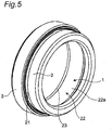
Fig. 5 is a perspective view showing the rotary electric machine according to the first embodiment. -
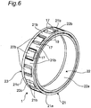
Fig. 6 is a perspective view showing the rotor of the rotary electric machine according to the first embodiment. -
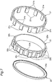
Fig. 7 is an exploded perspective view showing the rotor of the rotary electric machine according to the first embodiment. -
Figs. 8 (a) and 8 (b) are views showing the comparison between a member arrangement configuration according to the first embodiment and a member arrangement configuration according to the conventional example. -
Fig. 9 is a view showing a vertical cross section of a rotary electric machine according to a second embodiment of the present invention and also showing the arrangement relationship among the rotary electric machine, an engine and a transmission. -
Fig. 10 is a partial front view showing the rotary electric machine according to the second embodiment. -
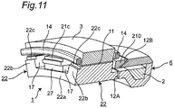
Fig. 11 is a vertically sectional perspective partial view showing the rotary electric machine according to the second embodiment, a magnetic pole holding member being not shown. - Embodiments of the present invention will be described below in detail referring to the accompanying drawings.
- As shown in
Figs. 1 to 3 , the rotary electric machine according to this embodiment is a brushless winding field type rotaryelectric machine 10 that is disposed between anengine 8 and atransmission 9 along arotation shaft 7 and positioned between astationary case 5 containing astarting device 4 and thestarting device 4. This rotaryelectric machine 10 is equipped with at least astator 3, afield coil 2 and arotor 1. - The
stator 3 is unrotatably fixed to and held in thestationary case 5, is constituted of a cylindrical member having a plurality of slots in which anAC coil 14 is wound, is provided with theAC coil 14 inside, and generates a rotating magnetic field by the AC current flowing in theAC coil 14. - The
field coil 2 is disposed while being shifted from thestator 3 and therotor 1 along therotation shaft 7, is fixed to and held in thestationary case 5 on thetransmission 9 side of thestator 3, and is excited by a DC current. Afield core 6 has thefield coil 2 inside. However, thefield coil 2 may be disposed while being shifted from thestator 3 and therotor 1 along therotation shaft 7 to theengine 8 side of thestator 3 via asecond air gap 12, instead of thetransmission 9 side of thestator 3, as shown in theregion 89 indicated by a dashed line inFig. 1 . - The
rotor 1 is disposed so as to be fixed to the outer periphery of thestarting device 4. The outer peripheral face of therotor 1 is opposed to the inner peripheral face of thestator 3, and the end face on thetransmission 9 side of therotor 1 is opposed to the end face on theengine 8 side of thefield coil 2. Therotor 1 is held so as to be rotatable with respect to thestator 3 and thefield coil 2 around therotation shaft 7. - A
first air gap 11 is formed between thestator 3 and therotor 1, thereby delivering a magnetic flux between thestator 3 and therotor 1. Thefirst air gap 11 is a gap extending along the axial direction of therotation shaft 7 between the inner peripheral face of thestator 3 and the outer peripheral face of therotor 1. - The
second air gap 12 is formed between thefield core 6 and therotor 1, thereby delivering the magnetic flux between thefield coil 2 and therotor 1. More specifically, thesecond air gap 12 has anair gap 12A formed between thefield core 6 and thesecond magnet pole 22 of therotor 1 and anair gap 12B formed between thefield core 6 and the firstmagnetic pole 21 of therotor 1. In other words, theair gap 12A is formed between thefield core 6 and the radially inner portion of the portion on thefield core 6 side of therotor 1. Theair gap 12B is formed between thefield core 6 and the radiallyouter portion 210 of the portion on thefield core 6 side of therotor 1. Theair gap 12A is formed so as to be perpendicular to the axial direction of therotation shaft 7. Theair gap 12B is formed so as to be inclined with respect to the axial direction of therotation shaft 7. More specifically, theair gap 12B is composed of a firstvertical section 121 being perpendicular to the axial direction of therotation shaft 7, aninclined section 122 inclined at an inclination angle α with respect to the axial direction of therotation shaft 7, and a secondvertical section 123 being perpendicular to the axial direction of therotation shaft 7. The firstvertical section 121, theinclined section 122 and the secondvertical section 123 are formed so as to be continuous. Furthermore, theinclined section 122 is inclined gradually from the side of theengine 8 to the side of thetransmission 9 as theinclined section 122 extends from the inside to the outside in the radial direction. Hence, the radiallyouter portion 210 on thefield core 6 side of therotor 1 is positioned on the radially outer side than thefield core 6. The inclination angle α is preferably in a range of 10 to 25 degrees. The gap widths of the firstvertical section 121, theinclined section 122 and the secondvertical section 123 are nearly the same. - Since the above-mentioned
second air gap 12 is formed between thefield core 6 and therotor 1, the radially outside portion of the portion on thefield core 6 side of therotor 1 has a beak shape in a vertical cross section protruding toward thefield core 6, and the portion on therotor 1 side of thefield core 6 has such a convex shape so as to get into the beak of therotor 1. - On the other hand, as shown in
Figs. 4 to 7 , therotor 1 is configured by combining the firstmagnetic pole 21, thesecond magnet pole 22 and a magneticpole holding member 23. The sectional view taken on the line A-A inFig. 4 corresponds to a sectional view showing the rotaryelectric machine 10, the startingdevice 4, etc. shown at the center ofFig. 1 . - The first
magnetic pole 21 is made from a soft magnetic material, such as iron, and has a plurality ofpawl sections 21b having, for example, a rectangular thin-plate shape, and protruding from a firstannular section 21a in the axial direction of therotation shaft 7. Thepawl sections 21b are disposed at constant intervals, for example, at equal intervals, in the circumferential direction, and the lengths of all thepawl sections 21b in the axial direction of therotation shaft 7 are the same. The outer peripheral faces of therespective pawl sections 21b are disposed along the outer peripheral face of the firstannular section 21a. Even in the case that the firstmagnetic pole 21 is combined with thesecond magnet pole 22, thepawl sections 21b do not make contact with thesecond magnet pole 22, and aradial clearance 16 is formed in the radial direction. - The second
magnetic pole 22 is made from a soft magnetic material, such as iron, and is disposed so that the radial clearance 16 (Fig. 1 ) is provided on the inside of the firstannular section 21a. The secondmagnetic pole 22 has a plurality ofconvex sections 22b having, for example, a rectangular plate shape, the convex sections radially protruding and being disposed while havingcircumferential clearances 17 in the circumferential direction on the outer peripheral face of a secondannular section 22a that is disposed so as to be partially overlapped with the firstannular section 21a. Theconvex sections 22b are also disposed at constant intervals, for example, at equal intervals, in the circumferential direction, and the radial heights of all theconvex sections 22b are the same. The lengths of all theconvex sections 22b in the axial direction of therotation shaft 7 are the same and shorter than the length of thepawl section 21b. The outer peripheral faces of the respectiveconvex sections 22b are disposed on a circle that has the same center as the center of the rotation axis of therotor 1. Eachconvex section 22b extends to the edge on theengine 8 side of the secondannular section 22a and is formed into a second tipend engagement section 22c. On the other hand, on thetransmission 9 side of the secondannular section 22a, eachconvex section 22b does not extend to the edge on thetransmission 9 side of the secondannular section 22a, and an annularfitting section 22d being narrow in width and not having theconvex sections 22b is formed. The firstmagnetic pole 21 and thesecond magnet pole 22 are assembled by moving the firstmagnetic pole 21 to thesecond magnet pole 22 in the axial direction and by inserting eachpawl section 21b of the firstmagnetic pole 21 into the intermediate section of thecircumferential clearance 17 between the adjacentconvex sections 22b so that thepawl sections 21b and theconvex sections 22b are disposed alternately in the circumferential direction. At this time, the assembling is performed so that the firstannular section 21a of the firstmagnetic pole 21 can be disposed on the outside of thefitting section 22d while theradial clearance 16 is provided therebetween. In the assembled state, as shown inFig. 6 , anaxial clearance 19 is provided between eachconvex section 22b and the firstannular section 21a, thecircumferential clearance 17 is provided in the circumferential direction between eachpawl section 21b and eachconvex section 22b of thesecond magnet pole 22, and theradial clearance 16 is also provided in the radial direction. Hence, the firstmagnetic pole 21 and thesecond magnet pole 22 are maintained in a noncontact state. The magneticpole holding member 23 is further provided in order to fix the firstmagnetic pole 21 and thesecond magnet pole 22 in this state. - The magnetic
pole holding member 23 is an annular member made from a nonmagnetic material, such as aluminum or austenitic stainless steel, and has afitting section 23a into which the first tipend engagement sections 21c of thepawl sections 21b of the firstmagnetic pole 21 are fitted and fixed and the second tipend engagement sections 22c of theconvex sections 22b of thesecond magnet pole 22 are fitted and fixed, for example, on the outer peripheral side. The first tipend engagement sections 21c and the second tipend engagement sections 22c are fitted into thefitting section 23a and then fixed, for example, by bolt fastening, shrink fitting or brazing, whereby the firstmagnetic pole 21 and thesecond magnet pole 22 are fixed and held by the magneticpole holding member 23 in a noncontact state. - The first tip
end engagement section 21c of thepawl section 21b of the firstmagnetic pole 21 and the second tipend engagement section 22c of theconvex section 22b of thesecond magnet pole 22 are each, as a specific example, formed into a step section, and the step section is fitted into the engagement concave section of thefitting section 23a, thereby being held so as to be fixed in the radial direction. Although the second tipend engagement section 22c is disposed, as an example, at the tip end of theconvex section 22b, the second tipend engagement section 22c may be disposed at the tip end of the secondannular section 22a. With this configuration, when the firstmagnetic pole 21 and thesecond magnet pole 22 are magnetized by making a magnetic flux flow from thefield coil 2, a magnetic flux short-circuit is prevented by the magneticpole holding member 23 made from a nonmagnetic material, whereby efficient magnetization can be performed and the firstmagnetic pole 21 and thesecond magnet pole 22 can be held mechanically by the magneticpole holding member 23. Moreover, since the first tipend engagement sections 21c of thepawl sections 21b of the firstmagnetic pole 21 are fitted and fixed to thefitting section 23a of the magneticpole holding member 23, the expansion of thepawl sections 21b due to a rotational centrifugal force can be suppressed, whereby the rotational strength can be improved. - In the rotary
electric machine 10 configured as described above, when thefield coil 2 is energized, a field coilmagnetic flux 15 is generated. The field coilmagnetic flux 15 is formed by starting from thefield core 6 and returning to thefield core 6 via the second air gap 12 (theair gap 12B), the firstmagnetic pole 21 of therotor 1, thefirst air gap 11, thestator 3, thefirst air gap 11, the secondmagnetic pole 22 of therotor 1, and the second air gap 12 (theair gap 12A) . At this time, for example, when a DC current is applied to thefield coil 2, the field coilmagnetic flux 15 is generated, whereby the firstmagnetic pole 21 and the secondmagnetic pole 22 are magnetized to, for example, an N pole and an S pole, respectively. - With the rotary
electric machine 10 configured as described above, a case in which a starting function is performed by using the rotaryelectric machine 10 as a starter will be described first. On the basis of a command for starting theengine 8, thestator 3 is magnetized by driving an inverter, not shown, and by applying a three-phase AC current to thestator 3, and a current is applied to thefield coil 2. The firstmagnetic pole 21 and the secondmagnetic pole 22 of therotor 1 are excited by applying the current to thefield coil 2. As a result, therotor 1 starts rotating with respect to thestator 3, and an electromotive force having an induction voltage is generated in thestator 3. - After that, the induction voltage increases as the rotation speed of the
rotor 1 increases. When the rotation speed reaches an initial-explosion rotation speed that is lower than the idling rotation speed corresponding to the idling of theengine 8 and the starting of theengine 8 is completed, the driving of the inverter is stopped. And then, the operation mode of the rotaryelectric machine 10 is automatically shifted to a power generation mode in which the rotaryelectric machine 10 operates as a generator to perform a power generation function so that the induction voltage is maintained at a predetermined induction voltage (required voltage). - In this power generation mode, when the
field coil 2 continues to be excited, the exciting current is adjusted so that the induction voltage becomes constant at the predetermined induction voltage. The exciting current is adjusted so that the magnetization force of the rotor decreases as the rotation speed increases, thereby making the induction voltage constant. Furthermore, in the case that thefield coil 2 is not excited, the lead angle of the three-phase AC current is adjusted by the inverter so that the induction voltage becomes constant at the predetermined induction voltage. Moreover, the adjustment may be made by combining the above-mentioned two methods. With this control, when therotor 1 is rotated, the rotaryelectric machine 10 functions as a generator. - As a result, the rotary
electric machine 10 can start the engine and can function as a generator during vehicle traveling by connecting the rotaryelectric machine 10 to theengine 8. - Next, working effects exerted by this embodiment will be described.
- (1) With this embodiment, since the
field coil 2 is shifted with respect to thestator 3 and therotor 1 in the axial direction of therotation shaft 7 as shown inFig. 8(a) , the following effects can be exerted.
First, in the conventional example, as shown inFig. 8(b) , the rotaryelectric machine 110 is disposed on the radial outside of the startingdevice 104, and the three members, i.e., thestator 103, therotor 101 and thefield coil 102, are disposed in the space between thestationary case 105 and the startingdevice 104 inward from the outside in the radial direction. In this case, if the number of turns of thefield coil 102 is increased to make the magnetic flux of the field coil larger, the radial thickness of the field coil becomes larger and the field coil cannot be inserted into the space, whereby the magnetic flux cannot be made larger.
On the other hand, in this embodiment, as shown inFig. 8(a) , thefield coil 2 is disposed in parallel with thestator 3 and therotor 1 while being shifted in the axial direction of therotation shaft 7. With this configuration, only the two members, i.e., thestator 3 and therotor 1, are provided on the radial outside of the startingdevice 4, whereby the disposition space for thefield coil 2 is not required on the radial outside of the startingdevice 4. Therefore, the outer radial dimension of the startingdevice 4 becomes smaller by at least the amount of the disposition space for thefield coil 2, or the thickness of thestator 3 or therotor 1 can be increased by the amount of the disposition space, whereby the area around the outer periphery of the startingdevice 4 can be utilized effectively. Furthermore, since thefield coil 2 is disposed at a position shifted from thestator 3 and therotor 1 in the axial direction, the radial thickness of thefield coil 2 can be increased and the magnetic flux of thefield coil 2 can be made larger without considering the spaces for thestator 3 and therotor 1. Consequently, the degree of freedom in design can be increased.
In addition, in such a radial disposition as shown inFig. 8(b) showing the conventional example, the concentricity (the adjustment of concentric positions) between therotor 101 on the rotation side and thefield coil 102 on the stationary side is strict. However, in the case that thefield coil 2 is shifted in the axial direction as shown inFig. 8 (b) showing this embodiment, the concentricity between therotor 1 on the rotation side and thefield coil 2 on the stationary side is not required to be adjusted so strictly as in the configuration shown inFig. 8 (b) .
Furthermore, in the configuration shown inFig. 8 (a) showing this embodiment, since thefield coil 2 can be disposed in the space either on the side of theengine 8 or on the side of thetransmission 9 in the axial direction of therotor 1, the space can be utilized effectively.
Moreover, in this embodiment, since the rotaryelectric machine 10 is disposed so that therotor 1 of the rotaryelectric machine 10 is connected to the startingdevice 4 serving as a synchronous rotation member synchronously rotating with the output shaft (the rotation shaft) 7 of theengine 8 and so that the center axis of the output shaft of theengine 8 serves as the rotation axis of therotor 1, the rotation drive force of the rotaryelectric machine 10 can be transmitted securely to theengine 8 even during a cold period, and theengine 8 can be started securely during the cold period.
Hence, with this embodiment, since therotor 1 and only either one of thestator 3 and thefield coil 2 are disposed in the narrow space between the inner peripheral side of thestationary case 5 and the outer peripheral side of the startingdevice 4, the two members may merely be disposed coaxially and on different diameters with therotation shaft 7, whereby the degree of freedom in design is enhanced and the output performance of the rotaryelectric machine 10 can be improved. - (2) With this embodiment, since the
second air gap 12 has theinclined section 122, the following effects can be exerted.
First, in the case that thesecond air gap 12 between therotor 1 and thefield coil 2 is formed so as to be perpendicular to the axial direction of therotation shaft 7 as in the conventional example, the following problems may occur.- (a) Since the cross-sectional area of the air gap is small, magnetic resistance rises, and the field current required for the rotor field may become large.
- (b) An electromagnetic attraction force is generated in the axial direction, and a large axial force may be exerted to the bearings (not shown) for holding the starting
device 4. - (c) In the cross section, the effective magnetic path width of the
second air gap 12 is nearly equal to the thickness of thefield core 6 and the thickness of the magnetic pole. What's more, when thefield core 6 is excited, an electromotive force is exerted between thefield core 6 and therotor 1, and the electromotive force entirely acts as an axial force.
second air gap 12 has theinclined section 122, the effective magnetic path width of thesecond air gap 12 can be increased in comparison with the conventional example. Furthermore, since the electromagnetic attraction force is dispersed not only to an axial force but also to a radial force, the axial force in this embodiment can be reduced in comparison with the conventional example. In other words, the electromagnetic attraction force in the axial direction is reduced, whereby the axial force exerted to the bearings can be reduced. Consequently, the drag torque of the rotary electric machine is reduced, whereby vehicle fuel consumption can be improved.
Furthermore, in this embodiment, since thesecond air gap 12 has theinclined section 122, the cross-sectional area of thesecond air gap 12 can be increased, whereby the magnetic resistance can be lowered and the field current can be reduced. Consequently, the efficiency of the rotaryelectric machine 10 is improved and vehicle fuel consumption can be further improved. - (3) In this embodiment, since the
air gap 12B of thesecond air gap 12 has theinclined section 122, the radially outsideportion 210 of the portion on thefield core 6 side of therotor 1 has a beak shape in a vertical cross section protruding toward thefield core 6, and the portion on therotor 1 side of thefield core 6 has such a convex shape in a vertical cross section so as to get into the beak of therotor 1. Hence, even if the radially outsideportion 210 on thefield core 6 side of therotor 1 expands to the outside in the radial direction due to the centrifugal force generated by rotation, the radially outsideportion 210 does not make contact with thefield core 6. In other words, the portion on thefield core 6 side of therotor 1 can be prevented from being expanded in diameter by a centrifugal force and from interfering with thefield core 6. - As shown in
Figs. 9 to 11 , in this embodiment,permanent magnets 27 are disposed inside therotor 1 in the configuration according to the first embodiment. - More specifically, the
permanent magnets 27 having, for example, a rectangular plate shape, are provided at the same circumferential positions as those of therespective pawl sections 21b of the firstmagnetic pole 21 and on the inner diameter sides of therespective pawl sections 21b of the firstmagnetic pole 21 and on the outer diameter side of the secondannular section 22a of the secondmagnetic pole 22 so as to be held between the inner peripheral faces of therespective pawl sections 21b and the outer peripheral face of the secondannular section 22a. With this disposition, as shown inFig. 10 , themagnetic flux 28 of thepermanent magnet 27 is formed between eachpawl section 21b of the firstmagnetic pole 21 and eachconvex section 22b of thesecond magnet pole 22. - The
permanent magnet 27 is a magnet mainly made from neodymium or a magnet mainly made from ferrite. More specifically, various kinds of permanent magnets, such as SmCo magnets, AlNiCo magnets or neodymium bonded magnets, can be used as thepermanent magnets 27. Eachpermanent magnet 27 is disposed on the whole inner face of eachpawl section 21b or part thereof. - With this configuration, the
magnetic flux 28 of thepermanent magnet 27 can be used in addition to the magnetic flux generated in therotor 1 by thefield coil 2, whereby the output performance of the rotary electric machine can be improved. Furthermore, since thepermanent magnets 27 are pressed and held with thepawl sections 21b, the strength of thepermanent magnets 27 against a centrifugal force can be reinforced, and the deformation of thepermanent magnets 27 due to the centrifugal force can be prevented, whereby the centrifugal strength at high speed rotation can be improved. -
- (a) The
air gap 12B may merely have theinclined section 122 and may not be required to have one or both of the firstvertical section 121 and the secondvertical section 123. - (b) The
air gap 12A may be formed so as to be inclined with respect to the axial direction of therotation shaft 7. The direction of the inclination is preferably a direction along which the inclination is formed from the side of theengine 8 to the side of thetransmission 9 as the inclination extends from the inside to the outside in the radial direction. With this configuration, even if the radially inside portion of therotor 1 expands to the outside in the radial direction due to the centrifugal force generated by rotation, the radially inside portion does not make contact with thefield core 6. The direction of the inclination may be a direction along which the inclination is formed from the side of thetransmission 9 to the side of theengine 8 as the inclination extends from the inside to the outside in the radial direction. - (c) The rotary
electric machine 10 may be disposed around the outer periphery of a rotary member other than the startingdevice 4. Examples of the other rotary members include a flywheel and a drive plate in a driving system. - By an appropriate combination of embodiments or modifications arbitrarily selected from the above-mentioned various embodiments or modifications, the respective effects of the embodiments or the modifications can be exerted. Furthermore, a combination of embodiments, a combination of working examples, or a combination of an embodiment and a working example is possible. Moreover, a combination of features of different embodiments or different working examples is also possible.
- The present invention is useful as a rotary electric machine for wide and general use in driving and power generating apparatuses, thereby having a high industrial applicability.
-
- 1:
- rotor
- 2:
- field coil
- 3:
- stator
- 4:
- starting device (rotation member)
- 5:
- stationary case
- 6:
- field core
- 7:
- rotation shaft
- 8:
- engine
- 9:
- transmission
- 10:
- rotary electric machine
- 11:
- first air gap
- 12:
- second air gap
- 122:
- inclined section
- 14:
- AC coil
- 21:
- first magnetic pole
- 21a:
- first annular section
- 21b:
- pawl section
- 21c:
- first tip end engagement section
- 210:
- (radially outer) portion
- 22:
- second magnetic pole
- 22a:
- second annular section
- 22b:
- convex section
- 22c:
- second tip end engagement section
- 22d:
- fitting section
- 23:
- magnetic pole holding member
- 23a:
- fitting section
- 27:
- permanent magnet
Claims (11)
- A brushless winding field type rotary electric machine (10) positioned between a rotary member and a stationary case (5), comprising:a stator (3) held in the stationary case (5) and internally equipped with an AC coil (14) for generating a rotating magnetic field by an AC current,a field core (6) held in the stationary case (5) and internally equipped with a field coil (2) excited by a DC current,a rotor (1) disposed around the outer periphery of the rotary member and held so as to be rotatable with respect to the stator (3) and the field coil (2),a first air gap (11) formed between the stator (3) and the rotor (1), thereby delivering a magnetic flux between the stator (3) and the rotor (1), anda second air gap (12) formed between the field core (6) and the rotor (1), thereby delivering a magnetic flux between the field coil (2) and the rotor (1), whereinthe field coil (2) of the field core (6) is disposed in parallel with the rotor (1) in the axial direction of the rotation shaft (7) of the rotary member via the second air gap (12), andthe second air gap (12) has an inclined section (122) inclined with respect to the axial direction of the rotation shaft (7) between the field core (6) and at least the radially outside portion of the portion on the field core (6) side of the rotor (1) so that the radially outer portion of the rotor (1) is positioned on the radially outer side than the field core (6).
- The rotary electric machine according to claim 1, wherein the radially outside portion of the portion on the field core (6) side of the rotor (1) has a beak shape in a vertical cross section protruding toward the field core (6), and
the portion on the rotor (1) side of the field core (6) has such a convex shape in a vertical cross section so as to get into the beak of the rotor (1). - The rotary electric machine according to claim 1 or 2, wherein
the second air gap (12) is equipped with the inclined section (122) and a vertical section formed so as to continue to the inclined section (122) and to be perpendicular to the rotation shaft (7). - The rotary electric machine according to any one of claims 1 to 3, wherein
the inclination angle of the inclined section (122) of the second air gap (12) is in a range of 10 to 25 degrees with respect to the axial direction of the rotation shaft (7). - The rotary electric machine according to any one of claims 1 to 4, wherein
the rotor (1) comprises:a first magnetic pole (21) having a plurality of pawl sections (21b) protruding from a first annular section (21a) in the axial direction of the rotation shaft (7),a second magnetic pole (22) being disposed so that a radial clearance is provided on the inside of the first annular section (21a) and having a plurality of convex sections (22b), the convex sections (22b) radially protruding and being disposed while having circumferential clearances in the circumferential direction on the outer peripheral face of a second annular section (22a) that is disposed so as to be partially overlapped with the first annular section (21a), andan annular magnetic pole holding member (23) having a fitting section (23a) into which the pawl sections (21b) of the first magnetic pole (21) and the convex sections (22b) of the second magnet pole (22) are fitted and fixed, whereinthe pawl sections (21b) of the first magnetic pole (21) are inserted into the clearances between the convex sections (22b) of the second magnet pole (22) such that the pawl sections (21b) of the first magnetic pole (21) and the convex sections (22b) of the second magnet pole (22) are disposed alternately in the circumferential direction, whereby the first magnetic pole (21) and the second magnet pole (22) are fitted and fixed to the magnetic pole holding member (23) without making contact with each other. - The rotary electric machine according to claim 5, wherein
the first tip end engagement sections (21c) of the pawl sections (21b) of the first magnetic pole (21) are fitted into the fitting section (23a) disposed on the outer peripheral side of the magnetic pole holding member (23), thereby being held so as to be fixed in the radial direction, and the second tip end engagement sections (22c) of the second magnet pole (22) are fitted into the fitting section (23a) of the magnetic pole holding member (23), thereby being held so as to be fixed in the radial direction. - The rotary electric machine according to claim 5 or 6, wherein
the magnetic pole holding member (23) is made from a nonmagnetic material. - The rotary electric machine according to any one of claims 5 to 7, wherein
each of the first magnetic pole (21) and the second magnet pole (22) is made from a soft magnetic material. - The rotary electric machine according to any one of claims 5 to 8, further comprising:
permanent magnets (27) provided at the same circumferential positions as those of the respective pawl sections (21b) of the first magnetic pole (21) and on the inner diameter side of the first magnetic pole (21) and on the outer diameter side of the second annular section (22a) of the second magnetic pole (22). - The rotary electric machine according to claim 9, wherein the permanent magnets (27) are mainly made from neodymium.
- The rotary electric machine according to claim 9, wherein the permanent magnets (27) are mainly made from ferrite.
Applications Claiming Priority (1)
| Application Number | Priority Date | Filing Date | Title |
|---|---|---|---|
| JP2018105415A JP7141250B2 (en) | 2018-05-31 | 2018-05-31 | Rotating electric machine |
Publications (1)
| Publication Number | Publication Date |
|---|---|
| EP3576266A1 true EP3576266A1 (en) | 2019-12-04 |
Family
ID=66676248
Family Applications (1)
| Application Number | Title | Priority Date | Filing Date |
|---|---|---|---|
| EP19177038.7A Withdrawn EP3576266A1 (en) | 2018-05-31 | 2019-05-28 | Rotary electric machine |
Country Status (4)
| Country | Link |
|---|---|
| US (1) | US10923970B2 (en) |
| EP (1) | EP3576266A1 (en) |
| JP (1) | JP7141250B2 (en) |
| CN (1) | CN110556992A (en) |
Citations (4)
| Publication number | Priority date | Publication date | Assignee | Title |
|---|---|---|---|---|
| US5929541A (en) * | 1996-11-26 | 1999-07-27 | Kinsiro Naito | Synchronous machine |
| US20020047433A1 (en) * | 1998-05-01 | 2002-04-25 | Tokuzou Sekiyama | Thrust-controllable rotary synchronous machine |
| JP3445492B2 (en) | 1998-05-25 | 2003-09-08 | 三菱電機株式会社 | Claw pole type brushless generator |
| JP2010516558A (en) | 2007-01-29 | 2010-05-20 | ルーク ラメレン ウント クツプルングスバウ ベタイリグングス コマンディートゲゼルシャフト | Powertrain with wet starting clutch for hybrid use |
Family Cites Families (14)
| Publication number | Priority date | Publication date | Assignee | Title |
|---|---|---|---|---|
| JP3464077B2 (en) * | 1995-05-30 | 2003-11-05 | 株式会社エヌエスエンジニアリング | Synchronous machine |
| US6794790B2 (en) * | 2002-03-20 | 2004-09-21 | Denso Corporation | Rotary electric machine |
| JP3829742B2 (en) | 2002-03-20 | 2006-10-04 | 株式会社デンソー | Rotating electric machine |
| US7129611B2 (en) * | 2003-05-22 | 2006-10-31 | Ut-Battelle Llc | Method and radial gap machine for high strength undiffused brushless operation |
| US6972504B1 (en) * | 2004-05-18 | 2005-12-06 | Ut-Battelle Llc | Permanent magnet machine and method with reluctance poles for high strength undiffused brushless operation |
| US8330319B2 (en) * | 2008-11-20 | 2012-12-11 | UT Batelle, LLC | Substantially parallel flux uncluttered rotor machines |
| CN102655363B (en) * | 2011-03-02 | 2014-11-26 | 株式会社丰田自动织机 | Rotary electric machine |
| CN102315739B (en) * | 2011-08-26 | 2013-02-06 | 北京航空航天大学 | Hybrid excitation generator |
| JP5673640B2 (en) * | 2012-02-29 | 2015-02-18 | アイシン・エィ・ダブリュ株式会社 | Hybrid excitation type rotating electric machine |
| US10270306B2 (en) * | 2014-01-29 | 2019-04-23 | Denso Corporation | Motor and rotor |
| JP6614986B2 (en) | 2016-02-02 | 2019-12-04 | 株式会社エクセディ | Power transmission device with rotating electric machine |
| JP7133970B2 (en) * | 2018-04-27 | 2022-09-09 | 株式会社エクセディ | Rotating electric machine |
| JP7144966B2 (en) * | 2018-04-27 | 2022-09-30 | 株式会社エクセディ | Rotating electric machine |
| JP7101531B2 (en) * | 2018-04-27 | 2022-07-15 | 株式会社エクセディ | Rotating electric machine |
-
2018
- 2018-05-31 JP JP2018105415A patent/JP7141250B2/en active Active
-
2019
- 2019-05-10 US US16/408,892 patent/US10923970B2/en active Active
- 2019-05-27 CN CN201910445796.4A patent/CN110556992A/en active Pending
- 2019-05-28 EP EP19177038.7A patent/EP3576266A1/en not_active Withdrawn
Patent Citations (4)
| Publication number | Priority date | Publication date | Assignee | Title |
|---|---|---|---|---|
| US5929541A (en) * | 1996-11-26 | 1999-07-27 | Kinsiro Naito | Synchronous machine |
| US20020047433A1 (en) * | 1998-05-01 | 2002-04-25 | Tokuzou Sekiyama | Thrust-controllable rotary synchronous machine |
| JP3445492B2 (en) | 1998-05-25 | 2003-09-08 | 三菱電機株式会社 | Claw pole type brushless generator |
| JP2010516558A (en) | 2007-01-29 | 2010-05-20 | ルーク ラメレン ウント クツプルングスバウ ベタイリグングス コマンディートゲゼルシャフト | Powertrain with wet starting clutch for hybrid use |
Also Published As
| Publication number | Publication date |
|---|---|
| US20190372407A1 (en) | 2019-12-05 |
| JP7141250B2 (en) | 2022-09-22 |
| CN110556992A (en) | 2019-12-10 |
| US10923970B2 (en) | 2021-02-16 |
| JP2019213292A (en) | 2019-12-12 |
Similar Documents
| Publication | Publication Date | Title |
|---|---|---|
| US10985638B2 (en) | Rotary electric machine | |
| US10848041B2 (en) | Rotating electric machine | |
| US10923970B2 (en) | Rotary electric machine having magnetic flux supplied from a field coil | |
| JP7215917B2 (en) | Rotating electric machine | |
| US11146138B2 (en) | Rotating electrical machine | |
| US10886799B2 (en) | Rotary electric machine | |
| EP3562008B1 (en) | Rotational electric machine | |
| EP3561290B1 (en) | Rotational electric machine | |
| JP4556408B2 (en) | Claw pole type rotating machine | |
| CN110417156B (en) | Rotary electric machine | |
| US10840786B2 (en) | Rotary electric machine having magnetic flux supplied from a field coil | |
| CN110417222B (en) | Rotary electric machine | |
| CN217036862U (en) | Rotor of rotating electric machine | |
| JP2010029038A (en) | Rotary electrical machine |
Legal Events
| Date | Code | Title | Description |
|---|---|---|---|
| PUAI | Public reference made under article 153(3) epc to a published international application that has entered the european phase |
Free format text: ORIGINAL CODE: 0009012 |
|
| AK | Designated contracting states |
Kind code of ref document: A1 Designated state(s): AL AT BE BG CH CY CZ DE DK EE ES FI FR GB GR HR HU IE IS IT LI LT LU LV MC MK MT NL NO PL PT RO RS SE SI SK SM TR |
|
| AX | Request for extension of the european patent |
Extension state: BA ME |
|
| 17P | Request for examination filed |
Effective date: 20200127 |
|
| RBV | Designated contracting states (corrected) |
Designated state(s): AL AT BE BG CH CY CZ DE DK EE ES FI FR GB GR HR HU IE IS IT LI LT LU LV MC MK MT NL NO PL PT RO RS SE SI SK SM TR |
|
| GRAP | Despatch of communication of intention to grant a patent |
Free format text: ORIGINAL CODE: EPIDOSNIGR1 |
|
| STAA | Information on the status of an ep patent application or granted ep patent |
Free format text: STATUS: GRANT OF PATENT IS INTENDED |
|
| RIC1 | Information provided on ipc code assigned before grant |
Ipc: H02K 19/24 20060101ALI20200708BHEP Ipc: H02K 21/44 20060101ALI20200708BHEP Ipc: H02K 19/10 20060101AFI20200708BHEP Ipc: H02K 21/04 20060101ALI20200708BHEP |
|
| INTG | Intention to grant announced |
Effective date: 20200723 |
|
| 18D | Application deemed to be withdrawn |
Effective date: 20201203 |