EP3576238A1 - A cable gland - Google Patents
A cable gland Download PDFInfo
- Publication number
- EP3576238A1 EP3576238A1 EP19176752.4A EP19176752A EP3576238A1 EP 3576238 A1 EP3576238 A1 EP 3576238A1 EP 19176752 A EP19176752 A EP 19176752A EP 3576238 A1 EP3576238 A1 EP 3576238A1
- Authority
- EP
- European Patent Office
- Prior art keywords
- cable
- gland
- gland body
- locking
- annular member
- Prior art date
- Legal status (The legal status is an assumption and is not a legal conclusion. Google has not performed a legal analysis and makes no representation as to the accuracy of the status listed.)
- Granted
Links
Images


Classifications
-
- H—ELECTRICITY
- H02—GENERATION; CONVERSION OR DISTRIBUTION OF ELECTRIC POWER
- H02G—INSTALLATION OF ELECTRIC CABLES OR LINES, OR OF COMBINED OPTICAL AND ELECTRIC CABLES OR LINES
- H02G15/00—Cable fittings
- H02G15/013—Sealing means for cable inlets
-
- G—PHYSICS
- G02—OPTICS
- G02B—OPTICAL ELEMENTS, SYSTEMS OR APPARATUS
- G02B6/00—Light guides; Structural details of arrangements comprising light guides and other optical elements, e.g. couplings
- G02B6/44—Mechanical structures for providing tensile strength and external protection for fibres, e.g. optical transmission cables
- G02B6/4439—Auxiliary devices
- G02B6/4471—Terminating devices ; Cable clamps
-
- H—ELECTRICITY
- H02—GENERATION; CONVERSION OR DISTRIBUTION OF ELECTRIC POWER
- H02G—INSTALLATION OF ELECTRIC CABLES OR LINES, OR OF COMBINED OPTICAL AND ELECTRIC CABLES OR LINES
- H02G15/00—Cable fittings
- H02G15/007—Devices for relieving mechanical stress
-
- H—ELECTRICITY
- H02—GENERATION; CONVERSION OR DISTRIBUTION OF ELECTRIC POWER
- H02G—INSTALLATION OF ELECTRIC CABLES OR LINES, OR OF COMBINED OPTICAL AND ELECTRIC CABLES OR LINES
- H02G15/00—Cable fittings
- H02G15/02—Cable terminations
- H02G15/04—Cable-end sealings
-
- H—ELECTRICITY
- H02—GENERATION; CONVERSION OR DISTRIBUTION OF ELECTRIC POWER
- H02G—INSTALLATION OF ELECTRIC CABLES OR LINES, OR OF COMBINED OPTICAL AND ELECTRIC CABLES OR LINES
- H02G3/00—Installations of electric cables or lines or protective tubing therefor in or on buildings, equivalent structures or vehicles
- H02G3/02—Details
- H02G3/06—Joints for connecting lengths of protective tubing or channels, to each other or to casings, e.g. to distribution boxes; Ensuring electrical continuity in the joint
- H02G3/0616—Joints for connecting tubing to casing
- H02G3/0625—Joints for connecting tubing to casing with means for preventing disengagement of conductors
- H02G3/0675—Joints for connecting tubing to casing with means for preventing disengagement of conductors with bolts operating in a direction parallel to the conductors
Definitions
- the present invention relates to the field of equipment and components for the insertion of optical cables in optical network closures, e.g. into an optical joint closure, optical network terminal, FTTA Hybrid distribution box or others optical junction boxes.
- the present invention relates to a cable gland.
- optical cables enter into optical network closures through cable glands, which are intended to provide a safe mechanical connection of the cable to the optical network closure.
- the cable contains a strength member configured to be fixed on the cable gland in order to secure the cable to the connection box.
- the hybrid cables such as those used in Fiber To The Antenna (FTTA) applications, do not contain the additional strength member as a standard optical fibre cable.
- the cable gland should secure the cable to the connection box without the strength member.
- a sufficient clamping force is required between the cable gland and the cable.
- US 6487344 discloses a watertight inlet device for inserting a cable containing optical fibers into a chamber or a container, e.g. into a splice box.
- the device includes a metal solepiece for securing the strength members of the optical cable, and which plugs into and fixes to a tubular sealing body equipped with an external O-ring gasket and having its rear portion shaped to form a sealing stuffing box on the outer sheath of the cable.
- the rear of the nut of the stuffing box receives a clamp for retaining the cable.
- EP 2902827 discloses a cable gland adapted to be secured to an optical joint closure.
- the cable gland comprises a central body longitudinally extended between a first end and a second end and configured for receiving a cable passing through these ends, wherein when the body is partially inserted in the optical joint closure, the first end is positioned inside the inner volume of the optical joint closure and the second end is positioned outside the optical joint closure, and a cable securing assembly configured to cooperate with the first end so that the cable securing assembly is attachable to the central body in order to retain and secure said optical cable.
- WO 2018047107 discloses a cable gland device for the electric interconnection of electric cables comprises.
- the cable gland comprises a first body made of an electrically insulating material having a first passage channel of an electric cable and a first tightening means of the electric cable inside the first passage channel.
- the cable gland further comprises a second body made of an electrically insulating material which comprises a second passage channel of the electric cable and is couplable to the first body for the activation of the first tightening means.
- the second body comprises the second tightening means of the electric cable inside the second passage channel.
- the Applicant has tackled the problem of providing a cable gland capable of tightening a cable without the strength member and providing a firm and reliable engagement between the cable and the gland, avoiding torsion or movements of the cable relative to the cable gland.
- the Applicant has found that providing a tightening element for a cable surrounded by a gland body and a locking arrangement for axially locking the tightening element and the gland body, a firm and reliable engagement between the cable and the gland is assured, reducing or avoiding any relative movement of the cable gland and cable.
- the present invention relates to a cable gland for securing a cable to a box, the cable gland comprising a tightening element configured to surround the cable, the tightening element having at least two connecting ends mutually approachable to tighten the tightening element on the cable, a gland body extending along an axial direction between a first end and a second end, the gland body defining a passing through channel extending along the axial direction between the first end and the second end and configured to receive the cable passing through the first and second ends, the gland body surrounding at least partially the tightening element, the cable gland comprises a first locking arrangement configured to lock along the axial direction the gland body relative to the tightening element, wherein the tightening element comprises first friction members configured to engage the cable.
- the tightening element has an outer surface facing the gland body and an inner surface facing the cable, the first friction members project from the inner surface.
- the first locking arrangement comprises a first locking element and a second locking element
- the first locking element of the first locking arrangement comprises a protrusion
- the second locking element of the first locking arrangement comprises a seat configured to receive and engage with the protrusion to axially lock the gland body relative to the tightening element.
- the first locking element of the first locking arrangement is associated with the tightening element and the second locking element of the first locking arrangement is associated with the gland body.
- the first locking arrangement is arranged at the first end of the gland body.
- the tightening element comprises a first semi annular member and a second semi annular member and connecting elements for mutually connecting the first and second semi annular members and tightening the tightening element on the cable.
- each first and second semi annular member has two connecting ends, the connecting ends of the first semi annular member are configured to be approached to the connecting ends of the second semi annular member through the connecting elements to tighten the tightening element on the cable.
- a seal is configured to surround the cable, the gland body at least partially surrounding the seal at the second end.
- annular member is arranged at the second end and is configured to surround and engage the cable, the annular member surrounds at least partially the gland body at the second end, a second locking arrangement is provided and configured to lock along the axial direction the gland body relative to the annular member.
- the annular member comprises second friction members configured to engage the cable.
- the second locking arrangement comprises a first locking element and a second locking element
- the first locking element of the second locking arrangement comprises a protrusion
- the second locking element of the second locking arrangement comprises a seat configured to receive and engage with the protrusion to axially lock the gland body relative to the annular member.
- the first locking element of the second locking arrangement is associated with the gland body and the second locking element of the second locking arrangement is associated with the annular member.
- the second locking arrangement is arranged at the second end of the gland body.
- the gland body comprises a heat-shrinkable sleeve surrounding at least partially the gland body at the first end and the cable.
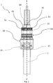
- the Figure 1 shows a cable gland 1 adapted to secure a cable 2 to a connection or distribution box 28.
- the cable 2 can be an electric cable, a hybrid cable or an optical fibre cable.
- the cable gland 1 comprises a tightening element 10 and a gland body 20.
- the tightening element 10 is associated to the gland body 20 and is configured to surround the cable 2 and to be tightened on the cable 2.
- the tightening element 10 comprises a first semi annular member 16 and a second semi annular member 17 and connecting elements 18 for mutually connecting the first semi annular member 16 and the second semi annular members 17, thereby tightening the tightening element 10 on the cable 2.
- first semi annular member 16 has two connecting ends 11, 12 and the second semi annular member 17 has two connecting ends 13, 14.
- the connecting ends 11, 12 of the first semi annular member 16 are configured to be approached to the connecting ends 13, 14 of the second semi annular member 17 through the connecting elements 18 to tighten the tightening element 10 on the cable 2. Therefore, approaching the connecting ends 11, 12, 13, 14 of the tightening element 10 increases the tightening of the tightening element 10 on the cable 2.
- the connecting elements 18 comprise fastening screws (not shown) passing through holes (not shown) formed in the semi annular members 16, 17.
- the connecting elements 18 allow to adjust the compression exerted on the cable 2 by the tightening element 10 and, therefore, to adjust the tightening of the tightening element 10 on the cable 2.
- the tightening element 10 has an outer surface 10a facing the gland body 20 and an inner surface 10b facing the cable 2.
- the inner surface 10b comprises friction members 15 configured to increase the grip of the tightening element 10 on the cable 2.
- the friction members 15 are protrusions projecting from the inner surface 10b of the tightening element 10 towards the cable 2.
- the gland body 20 is shaped so as to mutually approach and keep mutually approached the connecting ends 11, 12, 13, 14 of the tightening element 10 and thereby tightening the tightening element 10 on the cable 2.
- the inner surface 10b of the gland body 20 may be tapered so that the tapered inner surface 10b forces the connecting ends 11, 12, 13, 14 to mutually approach and tighten the tightening element 10 on the cable 2.
- the gland body 20 extends along an axial direction X-X between a first end 21 and a second end 22 opposed to the first end 21.
- the gland body 20 comprises a connecting portion 26 configured to connect the gland body 20 with a box 28, such as a distribution box, or to an optical joint closure.
- a box 28 such as a distribution box, or to an optical joint closure.
- the gland body 20 has an outer surface 20a and an opposite inner surface 20b facing the tightening element 10, in particular the outer surface 10b of the tightening element 10.
- the gland body 20 defines a passing through channel 23 extending between the first end 21 and the second end 22 along the axial direction X-X.
- the passing through channel 23 is configured to receive the cable 2 passing through the first end 21 and the second end 22.
- the gland body 20 at least partially surrounds the tightening element 10, preferably at the first end 21.
- the tightening element 10 is therefore arranged in the passing through channel 23.
- the gland body 20 completely surrounds the tightening element 10.
- the cable gland 1 comprises a first locking arrangement 30 configured to axially lock the tightening element 10 relative to the gland body 20. Thanks to this arrangement 30, the tightening element 10 is firmly attached to the gland body 20 and assures a firm and reliable engagement between the cable 2 and the gland body 20.
- the first locking arrangements 30 is preferably arranged at the first end 21 of the gland body 20.
- the first locking arrangement 30 comprises a first locking element 31 and a second locking element 32.
- the first locking element 31 is associated with the tightening element 10 and the second locking element 32 is associated with the gland body 20.
- the first locking element 31 is associated with the gland body 20 and the second locking element 32 is associated with the tightening element 10.
- the first locking element 31 and the second locking element 32 are configured to engage in order to lock the tightening element 10 relative to gland body 20.
- the first locking element 31 comprises a protrusion 33 and the second locking element 32 of the first locking arrangement 30 comprises a seat 34 configured to receive and engage with the protrusion 33 to axially lock the gland body 20 relative to the tightening element 10.
- the seat 34 comprises a first seat portion 35 extending along the axial direction X-X and configured to receive the protrusion and a second seat portion 36, joined to the first seat portion 35 and extending annularly along a direction perpendicular to the axial direction X-X to hold the protrusion 33.
- the first seat portion 35 allows an axial translation of the gland body 20 relative to the tightening element 10 while the second seat portion 36 allows lock of the gland body 20 relative to the tightening element 10. This also allows to easily lock and unlock the gland body 20 relative to tightening element 10.
- the first locking arrangement 30 allows a further compression of the tightening element 10 on the cable 2 and so increases the tightening of the cable gland 1 on the cable 2.
- the first locking element 31 comprises two protrusions 33, preferably two pins, projecting from the outer surface 10b of tightening element 10 and the second locking element 33 comprises two seats 34, preferably two slots, at the first end 21 of the gland body 20.
- the cable gland 1 further comprises a seal 24 configured to surround the cable 2 and arranged in the passing through channel 23 at the second end 22.
- the gland body 10 at least partially surrounds the seal 24 at the second end 22. Preferably the gland body 10 completely surrounds the seal 24.
- the seal 24 and the passing through channel 23 define an interference fit, so as to better tighten and secure the cable 2.
- the seal 24 has an annular shape and is configured to be mounted inside the passing through channel 23 to surround the cable, thereby providing additional retaining force between the cable 2 and the gland body 20.
- the seal 24 is made of rubber or any other suitable sealing material.
- the cable gland 1 further comprises an annular member 40 which is arranged at the second end 22 and configured to surround and engage the cable 2.
- the annular member 40 surrounds at least partially the gland body 20 at the second end 22.
- a second locking arrangement 50 is provided and configured to lock along the axial direction X-X the gland body 20 relative to the annular member 40.
- the annular member 40 comprises an inner sleeve 42, an outer sleeve 43 and a transverse wall 44 extending between the inner sleeve 42 and outer sleeve 43.
- the inner sleeve 42 engages the cable 2 and, preferably, comprises friction members 41 configured to increase the grip of the annular member 40 on the cable 2.
- the cable gland 1 comprises a second locking arrangement 50 configured to axially lock the gland body 20 relative to the annular member 40.
- the second locking arrangement 50 is located at the second end 22 of the gland body 20. Thanks to this second locking arrangement 50, the seal 24 is firmly held inside the gland body 20 and the annular member 40 avoids torsion and movements of the cable 2 relative to the cable gland 20.
- the second locking arrangement 50 is preferably arranged at the second end 22 of the gland body 20.
- the second locking arrangement 50 comprises a first locking element 51 and a second locking element 52.
- the first locking element 51 is associated with the gland body 20 and the second locking element 52 is associated with the annular member 40.
- the first locking element 51 is associated with the annular member 40 and the second locking element 52 is associated with the gland body 20.
- the first locking element 51 and the second locking element 52 are configured to engage in order to lock the annular member relative to gland body 20.
- the first locking element 51 comprises a protrusion 53 and the second locking element 52 comprises a seat 54 configured to receive and engage with the protrusion 53 to axially lock the gland body 20 relative to the annular member 40.
- the seat 54 comprises a first seat portion 55 extending along the axial direction X-X and configured to receive the protrusion 53 and a second seat portion 56, joined to the first seat portion 55 and extending annularly along a direction perpendicular to the axial direction X-X to hold the protrusion 53.
- the first seat portion 55 allows an axial translation of the annular member 50 relative to the gland body 20 while the second seat portion 56 allows axial lock of the annular member 40 relative to the gland body 20. This also allows to easily lock and unlock the gland body 20 relative to annular member 40.
- the second locking arrangement 50 allows a further compression of the seal 24 on the cable 2 and so increases the tightening and seal of the cable gland 1 on the cable 2.
- the first locking element 51 of the second locking arrangement 50 comprises two protrusions 53, preferably two pins, projecting from the outer surface 10b of the gland body 10 at the second end 22 and the second locking element 52 of the second locking arrangement 50 comprises two seats 54, preferably two lots, formed in the outer sleeve 43.
- the cable gland 1 comprises a heat-shrinkable sleeve 25 surrounding at least partially the gland body 20, at the first end 21, and the cable 2.
- the heat-shrinkable sleeve 25 is configured to protect the cable gland 2 against water or solids.
- the heat-shrinkable sleeve 25 increases the tightening force between the gland body 20 and the tightening element 10, reducing relative torsion between the gland body 20, the tightening element 10 and the cable 2.
- the cable gland 1 is assembled by mounting each component on an end of the cable 2.
- the heat-shrinkable sleeve 25 is mounted firstly, then the tightening element 10, the gland body 20, the seal 24 and the annular member 40.
- the tightening element 10 is tightened on the cable 2 by means of the fastening screws.
- the cable gland 20 is mounted on the tightening element 10 and tightening is obtained through the tapered inner surface 20b of the gland body 20.
- the gland body 20 is then locked relative to the tightening element 10 through the first locking arrangement 30. Then, preferably, the heat-shrinkable sleeve 25 is moved along the axial direction X-X towards the gland body 20 in order to cover the gland body 20 and the heat-shrinkable sleeve 25 is shrunk around the cable gland 20 by a heat treatment.
- further seals 27 are positioned between the cable gland 1 and the box 28 in order to protect the box 28 and the cable gland 1 against water flow or other type intrusions.
Landscapes
- Physics & Mathematics (AREA)
- General Physics & Mathematics (AREA)
- Optics & Photonics (AREA)
- Engineering & Computer Science (AREA)
- Architecture (AREA)
- Civil Engineering (AREA)
- Structural Engineering (AREA)
- Cable Accessories (AREA)
- Installation Of Indoor Wiring (AREA)
- Insulated Conductors (AREA)
- Superconductors And Manufacturing Methods Therefor (AREA)
Abstract
Description
- The present invention relates to the field of equipment and components for the insertion of optical cables in optical network closures, e.g. into an optical joint closure, optical network terminal, FTTA Hybrid distribution box or others optical junction boxes. In particular, the present invention relates to a cable gland.
- Typically, optical cables enter into optical network closures through cable glands, which are intended to provide a safe mechanical connection of the cable to the optical network closure.
- In order to avoid that external forces may cause the cable to be disconnected from the optical network closure, a strength member is required. Specifically, the cable contains a strength member configured to be fixed on the cable gland in order to secure the cable to the connection box.
- Frequently, the hybrid cables, such as those used in Fiber To The Antenna (FTTA) applications, do not contain the additional strength member as a standard optical fibre cable. With these hybrid cables, the cable gland should secure the cable to the connection box without the strength member. In particular, in order to avoid the cable retraction, a sufficient clamping force is required between the cable gland and the cable.
-
US 6487344 discloses a watertight inlet device for inserting a cable containing optical fibers into a chamber or a container, e.g. into a splice box. The device includes a metal solepiece for securing the strength members of the optical cable, and which plugs into and fixes to a tubular sealing body equipped with an external O-ring gasket and having its rear portion shaped to form a sealing stuffing box on the outer sheath of the cable. The rear of the nut of the stuffing box receives a clamp for retaining the cable. Once the device has been fitted, the resulting assembly is inserted into the inlet passageway until it abuts against a shoulder in the passageway. Then only the head of the securing solepiece and a groove in the body project inside the container, the groove then receiving a key or fork for retaining the assembly. -
EP 2902827 discloses a cable gland adapted to be secured to an optical joint closure. The cable gland comprises a central body longitudinally extended between a first end and a second end and configured for receiving a cable passing through these ends, wherein when the body is partially inserted in the optical joint closure, the first end is positioned inside the inner volume of the optical joint closure and the second end is positioned outside the optical joint closure, and a cable securing assembly configured to cooperate with the first end so that the cable securing assembly is attachable to the central body in order to retain and secure said optical cable. -
WO 2018047107 discloses a cable gland device for the electric interconnection of electric cables comprises. The cable gland comprises a first body made of an electrically insulating material having a first passage channel of an electric cable and a first tightening means of the electric cable inside the first passage channel. The cable gland further comprises a second body made of an electrically insulating material which comprises a second passage channel of the electric cable and is couplable to the first body for the activation of the first tightening means. Specifically, the second body comprises the second tightening means of the electric cable inside the second passage channel. - The Applicant has tackled the problem of providing a cable gland capable of tightening a cable without the strength member and providing a firm and reliable engagement between the cable and the gland, avoiding torsion or movements of the cable relative to the cable gland.
- The Applicant has found that providing a tightening element for a cable surrounded by a gland body and a locking arrangement for axially locking the tightening element and the gland body, a firm and reliable engagement between the cable and the gland is assured, reducing or avoiding any relative movement of the cable gland and cable.
- Therefore, the present invention relates to a cable gland for securing a cable to a box, the cable gland comprising a tightening element configured to surround the cable, the tightening element having at least two connecting ends mutually approachable to tighten the tightening element on the cable, a gland body extending along an axial direction between a first end and a second end, the gland body defining a passing through channel extending along the axial direction between the first end and the second end and configured to receive the cable passing through the first and second ends, the gland body surrounding at least partially the tightening element, the cable gland comprises a first locking arrangement configured to lock along the axial direction the gland body relative to the tightening element, wherein the tightening element comprises first friction members configured to engage the cable.
- Preferably, the tightening element has an outer surface facing the gland body and an inner surface facing the cable, the first friction members project from the inner surface.
- Preferably, the first locking arrangement comprises a first locking element and a second locking element, the first locking element of the first locking arrangement comprises a protrusion and the second locking element of the first locking arrangement comprises a seat configured to receive and engage with the protrusion to axially lock the gland body relative to the tightening element.
- Preferably, the first locking element of the first locking arrangement is associated with the tightening element and the second locking element of the first locking arrangement is associated with the gland body.
- Preferably, the first locking arrangement is arranged at the first end of the gland body.
- Preferably, the tightening element comprises a first semi annular member and a second semi annular member and connecting elements for mutually connecting the first and second semi annular members and tightening the tightening element on the cable.
- Preferably, each first and second semi annular member has two connecting ends, the connecting ends of the first semi annular member are configured to be approached to the connecting ends of the second semi annular member through the connecting elements to tighten the tightening element on the cable.
- Preferably, a seal is configured to surround the cable, the gland body at least partially surrounding the seal at the second end.
- Preferably, an annular member is arranged at the second end and is configured to surround and engage the cable, the annular member surrounds at least partially the gland body at the second end, a second locking arrangement is provided and configured to lock along the axial direction the gland body relative to the annular member.
- Preferably, the annular member comprises second friction members configured to engage the cable.
- Preferably, the second locking arrangement comprises a first locking element and a second locking element, the first locking element of the second locking arrangement comprises a protrusion and the second locking element of the second locking arrangement comprises a seat configured to receive and engage with the protrusion to axially lock the gland body relative to the annular member.
- Preferably, the first locking element of the second locking arrangement is associated with the gland body and the second locking element of the second locking arrangement is associated with the annular member.
- Preferably, the second locking arrangement is arranged at the second end of the gland body.
- Preferably, the gland body comprises a heat-shrinkable sleeve surrounding at least partially the gland body at the first end and the cable.
- The present invention will now be described in more detail hereinafter with reference to the accompanying drawings, in which some embodiments of the invention are shown.
-
FIG. 1 is a schematic view of a cable gland in an assembled configuration on a cable according to one embodiment of the present invention, -
FIG. 2 is a first section view of the cable gland ofFIG. 1 , -
FIG. 3 is an exploded view of the cable gland of theFIG. 1 , -
FIG. 4 is a second section view of the cable gland ofFIG. 1 , -
FIG. 5 is a front view of a component of the cable gland ofFIG.1 , -
FIG. 6 is a top view of the component ofFIG. 5 -
FIG. 7 is schematic view of the cable glandFIG. 1 in an assembled configuration when connected to a connection box. - The
Figure 1 shows acable gland 1 adapted to secure acable 2 to a connection ordistribution box 28. Thecable 2 can be an electric cable, a hybrid cable or an optical fibre cable. - The
cable gland 1 comprises a tighteningelement 10 and agland body 20. - The tightening
element 10 is associated to thegland body 20 and is configured to surround thecable 2 and to be tightened on thecable 2. - According to the one embodiment, the tightening
element 10 comprises a first semiannular member 16 and a second semiannular member 17 and connectingelements 18 for mutually connecting the first semiannular member 16 and the second semiannular members 17, thereby tightening the tighteningelement 10 on thecable 2. - In particular, the first semi
annular member 16 has two connectingends annular member 17 has two connectingends - The connecting
ends annular member 16 are configured to be approached to the connectingends annular member 17 through the connectingelements 18 to tighten thetightening element 10 on thecable 2. Therefore, approaching the connectingends element 10 increases the tightening of the tighteningelement 10 on thecable 2. - Preferably, the connecting
elements 18 comprise fastening screws (not shown) passing through holes (not shown) formed in the semiannular members - Advantageously, the connecting
elements 18 allow to adjust the compression exerted on thecable 2 by the tighteningelement 10 and, therefore, to adjust the tightening of the tighteningelement 10 on thecable 2. - The tightening
element 10 has anouter surface 10a facing thegland body 20 and aninner surface 10b facing thecable 2. - The
inner surface 10b comprisesfriction members 15 configured to increase the grip of the tighteningelement 10 on thecable 2. Preferably thefriction members 15 are protrusions projecting from theinner surface 10b of the tighteningelement 10 towards thecable 2. - Approaching the
connecting ends element 10 allows theprotrusions 15 to act on the outer surface of thecable 2 and increases the gripping force of the tighteningelement 10 on thecable 2, thereby avoiding torsion and movements of thecable 2 relative to the tighteningelement 10. - According to an alternative embodiment, the
gland body 20 is shaped so as to mutually approach and keep mutually approached the connectingends element 10 and thereby tightening the tighteningelement 10 on thecable 2. For example, theinner surface 10b of thegland body 20 may be tapered so that the taperedinner surface 10b forces the connectingends element 10 on thecable 2. - The
gland body 20 extends along an axial direction X-X between afirst end 21 and asecond end 22 opposed to thefirst end 21. - Preferably, the
gland body 20 comprises a connectingportion 26 configured to connect thegland body 20 with abox 28, such as a distribution box, or to an optical joint closure. - The
gland body 20 has an outer surface 20a and an opposite inner surface 20b facing the tighteningelement 10, in particular theouter surface 10b of the tighteningelement 10. - The
gland body 20 defines a passing throughchannel 23 extending between thefirst end 21 and thesecond end 22 along the axial direction X-X. The passing throughchannel 23 is configured to receive thecable 2 passing through thefirst end 21 and thesecond end 22. - The
gland body 20 at least partially surrounds the tighteningelement 10, preferably at thefirst end 21. The tighteningelement 10 is therefore arranged in the passing throughchannel 23. - Preferably, the
gland body 20 completely surrounds the tighteningelement 10. - The
cable gland 1 comprises afirst locking arrangement 30 configured to axially lock the tighteningelement 10 relative to thegland body 20. Thanks to thisarrangement 30, the tighteningelement 10 is firmly attached to thegland body 20 and assures a firm and reliable engagement between thecable 2 and thegland body 20. - The
first locking arrangements 30 is preferably arranged at thefirst end 21 of thegland body 20. - The
first locking arrangement 30 comprises afirst locking element 31 and asecond locking element 32. In the embodiment shown in the figures, thefirst locking element 31 is associated with the tighteningelement 10 and thesecond locking element 32 is associated with thegland body 20. Alternatively, thefirst locking element 31 is associated with thegland body 20 and thesecond locking element 32 is associated with the tighteningelement 10. - The
first locking element 31 and thesecond locking element 32 are configured to engage in order to lock the tighteningelement 10 relative togland body 20. - Preferably, the
first locking element 31 comprises aprotrusion 33 and thesecond locking element 32 of thefirst locking arrangement 30 comprises aseat 34 configured to receive and engage with theprotrusion 33 to axially lock thegland body 20 relative to the tighteningelement 10. In particular, theseat 34 comprises afirst seat portion 35 extending along the axial direction X-X and configured to receive the protrusion and asecond seat portion 36, joined to thefirst seat portion 35 and extending annularly along a direction perpendicular to the axial direction X-X to hold theprotrusion 33. Thefirst seat portion 35 allows an axial translation of thegland body 20 relative to the tighteningelement 10 while thesecond seat portion 36 allows lock of thegland body 20 relative to the tighteningelement 10. This also allows to easily lock and unlock thegland body 20 relative to tighteningelement 10. - Advantageously, the
first locking arrangement 30 allows a further compression of the tighteningelement 10 on thecable 2 and so increases the tightening of thecable gland 1 on thecable 2. - According to the embodiment shown in the figures, the
first locking element 31 comprises twoprotrusions 33, preferably two pins, projecting from theouter surface 10b of tighteningelement 10 and thesecond locking element 33 comprises twoseats 34, preferably two slots, at thefirst end 21 of thegland body 20. - The
cable gland 1 further comprises aseal 24 configured to surround thecable 2 and arranged in the passing throughchannel 23 at thesecond end 22. - The
gland body 10 at least partially surrounds theseal 24 at thesecond end 22. Preferably thegland body 10 completely surrounds theseal 24. - Preferably, the
seal 24 and the passing throughchannel 23 define an interference fit, so as to better tighten and secure thecable 2. - Preferably, the
seal 24 has an annular shape and is configured to be mounted inside the passing throughchannel 23 to surround the cable, thereby providing additional retaining force between thecable 2 and thegland body 20. - Preferably, the
seal 24 is made of rubber or any other suitable sealing material. - The
cable gland 1 further comprises anannular member 40 which is arranged at thesecond end 22 and configured to surround and engage thecable 2. - The
annular member 40 surrounds at least partially thegland body 20 at thesecond end 22. - A
second locking arrangement 50 is provided and configured to lock along the axial direction X-X thegland body 20 relative to theannular member 40. - According to one embodiment, the
annular member 40 comprises aninner sleeve 42, anouter sleeve 43 and atransverse wall 44 extending between theinner sleeve 42 andouter sleeve 43. - The
inner sleeve 42 engages thecable 2 and, preferably, comprisesfriction members 41 configured to increase the grip of theannular member 40 on thecable 2. - The
cable gland 1 comprises asecond locking arrangement 50 configured to axially lock thegland body 20 relative to theannular member 40. Thesecond locking arrangement 50 is located at thesecond end 22 of thegland body 20. Thanks to thissecond locking arrangement 50, theseal 24 is firmly held inside thegland body 20 and theannular member 40 avoids torsion and movements of thecable 2 relative to thecable gland 20. - The
second locking arrangement 50 is preferably arranged at thesecond end 22 of thegland body 20. - The
second locking arrangement 50 comprises afirst locking element 51 and asecond locking element 52. In the embodiment shown in the figures, thefirst locking element 51 is associated with thegland body 20 and thesecond locking element 52 is associated with theannular member 40. Alternatively, thefirst locking element 51 is associated with theannular member 40 and thesecond locking element 52 is associated with thegland body 20. - The
first locking element 51 and thesecond locking element 52 are configured to engage in order to lock the annular member relative togland body 20. - Preferably, the
first locking element 51 comprises aprotrusion 53 and thesecond locking element 52 comprises aseat 54 configured to receive and engage with theprotrusion 53 to axially lock thegland body 20 relative to theannular member 40. In particular, theseat 54 comprises afirst seat portion 55 extending along the axial direction X-X and configured to receive theprotrusion 53 and asecond seat portion 56, joined to thefirst seat portion 55 and extending annularly along a direction perpendicular to the axial direction X-X to hold theprotrusion 53. Thefirst seat portion 55 allows an axial translation of theannular member 50 relative to thegland body 20 while thesecond seat portion 56 allows axial lock of theannular member 40 relative to thegland body 20. This also allows to easily lock and unlock thegland body 20 relative toannular member 40. - Advantageously, the
second locking arrangement 50 allows a further compression of theseal 24 on thecable 2 and so increases the tightening and seal of thecable gland 1 on thecable 2. - According to one embodiment, the
first locking element 51 of thesecond locking arrangement 50 comprises twoprotrusions 53, preferably two pins, projecting from theouter surface 10b of thegland body 10 at thesecond end 22 and thesecond locking element 52 of thesecond locking arrangement 50 comprises twoseats 54, preferably two lots, formed in theouter sleeve 43. - According to one embodiment, the
cable gland 1 comprises a heat-shrinkable sleeve 25 surrounding at least partially thegland body 20, at thefirst end 21, and thecable 2. The heat-shrinkable sleeve 25 is configured to protect thecable gland 2 against water or solids. - Advantageously, the heat-
shrinkable sleeve 25 increases the tightening force between thegland body 20 and the tighteningelement 10, reducing relative torsion between thegland body 20, the tighteningelement 10 and thecable 2. - The
cable gland 1 is assembled by mounting each component on an end of thecable 2. Preferably the heat-shrinkable sleeve 25 is mounted firstly, then the tighteningelement 10, thegland body 20, theseal 24 and theannular member 40. - After the heat-
shrinkable sleeve 25 is mounted, the tighteningelement 10 is tightened on thecable 2 by means of the fastening screws. Alternatively, thecable gland 20 is mounted on the tighteningelement 10 and tightening is obtained through the tapered inner surface 20b of thegland body 20. - The
gland body 20 is then locked relative to the tighteningelement 10 through thefirst locking arrangement 30. Then, preferably, the heat-shrinkable sleeve 25 is moved along the axial direction X-X towards thegland body 20 in order to cover thegland body 20 and the heat-shrinkable sleeve 25 is shrunk around thecable gland 20 by a heat treatment. - Then the
seal 24 is inserted with interference inside thegland body 20 at thesecond end 22 and theannular member 40 is mutually locked relative to thegland body 20 at thesecond end 22. Finally, the assembledcable gland 1 is connected to thebox 28 through the connectingportion 26. - Preferably, further seals 27 are positioned between the
cable gland 1 and thebox 28 in order to protect thebox 28 and thecable gland 1 against water flow or other type intrusions.
Claims (14)
- A cable gland (1) for securing a cable (2) to a box (28), the cable gland (1) comprising:- a tightening element (10) configured to surround the cable (2), the tightening element (10) having at least two connecting ends (11,12,13,14) mutually approachable to tighten the tightening element (10) on the cable (2),- a gland body (20) extending along an axial direction (X-X) between a first end (21) and a second end (22), the gland body (20) defining a passing through channel (23) extending along the axial direction (X-X) between the first end (21) and the second end (22) and configured to receive the cable (2) passing through the first and second ends (21,22), the gland body (20) surrounding at least partially the tightening element (10),the cable gland (1) comprises a first locking arrangement (30) configured to lock along the axial direction (X-X) the gland body (20) relative to the tightening element (10),
wherein- the tightening element (10) comprises first friction members (15) configured to engage the cable (2). - The cable gland (1) according to claim 1, wherein:- the tightening element (10) has an outer surface (10a) facing the gland body (20) and an inner surface (10b) facing the cable (2);- the first friction members (15) project from the inner surface (10b).
- The cable gland (1) according to claim 1 or 2, wherein:- the first locking arrangement (30) comprises a first locking element (31) and a second locking element (32),- the first locking element (31) of the first locking arrangement (30) comprises a protrusion (33) and the second locking element (32) of the first locking arrangement (30) comprises a seat (34) configured to receive and engage with the protrusion (33) to axially lock the gland body (20) relative to the tightening element (10).
- The cable gland (1) according to claim 3, wherein:- the first locking element (31) of the first locking arrangement (30) is associated with the tightening element (10) and the second locking element (32) of the first locking arrangement (30) is associated with the gland body (20).
- The cable gland (1) according to anyone of claims 1 to 4, wherein the first locking arrangement (30) is arranged at the first end (21) of the gland body (20).
- The cable gland (1) according to anyone of claims 1 to 5, wherein the tightening element (10) comprises a first semi annular member (16) and a second semi annular member (17) and connecting elements (18) for mutually connecting the first (16) and second semi annular members (17) and tightening the tightening element (10) on the cable (2).
- The cable gland (1) according to claim 6, wherein each first (16) and second semi annular member (17) has two connecting ends (11, 12, 13, 14), the connecting ends (11, 12) of the first semi annular member (16) are configured to be approached to the connecting ends (13, 14) of the second semi annular member (17) through the connecting elements (18) to tighten the tightening element (10) on the cable (2).
- The cable gland (1) according to any of claims 1 to 7, wherein a seal (24) is configured to surround the cable (2), the gland body (10) at least partially surrounding the seal (24) at the second end (22).
- The cable gland (1) according to any claims 1 to 8, wherein:- an annular member (40) is arranged at the second end (22) and is configured to surround and engage the cable (2),- the annular member (40) surrounds at least partially the gland body (20) at the second end (22),- a second locking arrangement (50) is provided and configured to lock along the axial direction (X-X) the gland body (20) relative to the annular member (40).
- The cable gland (1) according to claim 9, wherein the annular member (40) comprises second friction members (41) configured to engage the cable (2).
- The cable gland (1) according to claim 9 or 10, wherein:- the second locking arrangement (50) comprises a first locking element (51) and a second locking element (52),- the first locking element (51) of the second locking arrangement (50) comprises a protrusion (53) and the second locking element (52) of the second locking arrangement (50) comprises a seat (54) configured to receive and engage with the protrusion (53) to axially lock the gland body (20) relative to the annular member (40).
- The cable gland (1) according to claim 11, wherein:- the first locking element (51) of the second locking arrangement (50) is associated with the gland body (20) and the second locking element (52) of the second locking arrangement (50) is associated with the annular member (40).
- The cable gland (1) according to anyone of claims 9 to 12, wherein the second locking arrangement (50) is arranged at the second end (22) of the gland body (20).
- The cable gland (1) according to anyone of claims 1 to 13, wherein the gland body (20) comprises a heat-shrinkable sleeve (25) surrounding at least partially the gland body (20) at the first end (21) and the cable (2).
Applications Claiming Priority (1)
| Application Number | Priority Date | Filing Date | Title |
|---|---|---|---|
| IT102018000005960A IT201800005960A1 (en) | 2018-06-01 | 2018-06-01 | Cable gland |
Publications (3)
| Publication Number | Publication Date |
|---|---|
| EP3576238A1 true EP3576238A1 (en) | 2019-12-04 |
| EP3576238B1 EP3576238B1 (en) | 2023-07-05 |
| EP3576238C0 EP3576238C0 (en) | 2023-07-05 |
Family
ID=63312368
Family Applications (1)
| Application Number | Title | Priority Date | Filing Date |
|---|---|---|---|
| EP19176752.4A Active EP3576238B1 (en) | 2018-06-01 | 2019-05-27 | A cable gland |
Country Status (6)
| Country | Link |
|---|---|
| US (1) | US11502497B2 (en) |
| EP (1) | EP3576238B1 (en) |
| AU (1) | AU2019203690B2 (en) |
| ES (1) | ES2959693T3 (en) |
| IT (1) | IT201800005960A1 (en) |
| PL (1) | PL3576238T3 (en) |
Citations (7)
| Publication number | Priority date | Publication date | Assignee | Title |
|---|---|---|---|---|
| DE10027486A1 (en) * | 2000-06-02 | 2001-12-13 | Rapp Wildner Heike | Cable bush system penetrating casing walls, comprises snap-in outer sleeve, cone plug and split bush with variable opening |
| US6487344B1 (en) | 1998-08-04 | 2002-11-26 | Pouyet S.A. | Optical fiber cable inlet device |
| WO2015068581A1 (en) * | 2013-11-06 | 2015-05-14 | 住友電装株式会社 | Wire harness |
| EP2902827A1 (en) | 2014-02-03 | 2015-08-05 | Prysmian S.p.A. | Cable gland |
| US9312672B2 (en) * | 2013-09-26 | 2016-04-12 | Panduit Corp. | Threaded sleeve compressed split cable gland |
| WO2018047107A1 (en) | 2016-09-09 | 2018-03-15 | Techno Group S.R.L. | Cable gland device for the electric interconnection of electric cables |
| US20180109093A1 (en) * | 2016-10-18 | 2018-04-19 | CAPE Industries, LLC | Cable gland and method and apparatus for earthing a cable |
Family Cites Families (8)
| Publication number | Priority date | Publication date | Assignee | Title |
|---|---|---|---|---|
| US4842364A (en) * | 1988-10-11 | 1989-06-27 | Jack Moon Co. Ltd., Taiwan | Fiber optic cable innerduct plug and assembly |
| US6268565B1 (en) * | 1999-12-06 | 2001-07-31 | Avaya Technology Corp. | Cable seal for submerged enclosures |
| US6462275B1 (en) * | 1999-12-17 | 2002-10-08 | Avaya Technology Corp. | Cable sealing device and system |
| US8967556B2 (en) * | 2012-03-13 | 2015-03-03 | Newfrey Llc | Two shot tube retention clip with resilient living hinge |
| US9510491B2 (en) * | 2014-02-17 | 2016-11-29 | Lear Corporation | Electromagnetic shield termination device |
| US9461401B2 (en) * | 2014-12-22 | 2016-10-04 | Selvin Kao | Electrical plugs with integrated strain relief and method of manufacture |
| EP3093929A1 (en) * | 2015-05-15 | 2016-11-16 | ERICH JAEGER GmbH + Co. KG | Strain relief element for a cable and plug with strain relief element |
| US10094491B1 (en) * | 2017-10-17 | 2018-10-09 | Wanho T Manufacturing Co., Ltd. | Organizing device for cable and wire |
-
2018
- 2018-06-01 IT IT102018000005960A patent/IT201800005960A1/en unknown
-
2019
- 2019-05-27 PL PL19176752.4T patent/PL3576238T3/en unknown
- 2019-05-27 AU AU2019203690A patent/AU2019203690B2/en active Active
- 2019-05-27 EP EP19176752.4A patent/EP3576238B1/en active Active
- 2019-05-27 ES ES19176752T patent/ES2959693T3/en active Active
- 2019-05-29 US US16/424,770 patent/US11502497B2/en active Active
Patent Citations (7)
| Publication number | Priority date | Publication date | Assignee | Title |
|---|---|---|---|---|
| US6487344B1 (en) | 1998-08-04 | 2002-11-26 | Pouyet S.A. | Optical fiber cable inlet device |
| DE10027486A1 (en) * | 2000-06-02 | 2001-12-13 | Rapp Wildner Heike | Cable bush system penetrating casing walls, comprises snap-in outer sleeve, cone plug and split bush with variable opening |
| US9312672B2 (en) * | 2013-09-26 | 2016-04-12 | Panduit Corp. | Threaded sleeve compressed split cable gland |
| WO2015068581A1 (en) * | 2013-11-06 | 2015-05-14 | 住友電装株式会社 | Wire harness |
| EP2902827A1 (en) | 2014-02-03 | 2015-08-05 | Prysmian S.p.A. | Cable gland |
| WO2018047107A1 (en) | 2016-09-09 | 2018-03-15 | Techno Group S.R.L. | Cable gland device for the electric interconnection of electric cables |
| US20180109093A1 (en) * | 2016-10-18 | 2018-04-19 | CAPE Industries, LLC | Cable gland and method and apparatus for earthing a cable |
Also Published As
| Publication number | Publication date |
|---|---|
| PL3576238T3 (en) | 2023-12-11 |
| AU2019203690A1 (en) | 2019-12-19 |
| US20190372329A1 (en) | 2019-12-05 |
| ES2959693T3 (en) | 2024-02-27 |
| US11502497B2 (en) | 2022-11-15 |
| BR102019011034A2 (en) | 2019-12-03 |
| EP3576238B1 (en) | 2023-07-05 |
| EP3576238C0 (en) | 2023-07-05 |
| AU2019203690B2 (en) | 2024-09-19 |
| IT201800005960A1 (en) | 2019-12-01 |
Similar Documents
| Publication | Publication Date | Title |
|---|---|---|
| EP3353868B1 (en) | Cable gland assembly | |
| US10061091B2 (en) | Cable sealing device, cable termination and attaching device | |
| US8556649B2 (en) | Fixing device for fixing a cable at a housing feed-through | |
| US6113429A (en) | Plug-type coupling for sheathed electrical cables | |
| PL196633B1 (en) | Leak-tight light-fibre cable bushing assembly | |
| KR102290813B1 (en) | Enclosure for connector on cable | |
| US20200076175A1 (en) | Holding Device for Holding a Shielded Cable | |
| US5315489A (en) | Pressure clamp for telecommunications closure | |
| KR20000076339A (en) | External ground isolation connector for cable splice closures | |
| EP3576238B1 (en) | A cable gland | |
| WO2018148814A1 (en) | Connector for an optical fibre cable and jaw for an optical fibre cable | |
| JPH0568926B2 (en) | ||
| GB2178909A (en) | Cable barrier gland | |
| KR20150004828A (en) | Quick one-way connection system | |
| KR20220125264A (en) | Clamping devices for cable connector assemblies | |
| KR102606711B1 (en) | cable connector assembly | |
| EP3608698B1 (en) | A gland for securing tubes or cables | |
| EP2355285A1 (en) | Cable sealing and retaining device and cable connection | |
| BR102019011034B1 (en) | CABLE GLAND FOR ATTACHING A CABLE TO A BOX | |
| AU773336B2 (en) | Electrical cable gland | |
| GB1603523A (en) | Cable glands | |
| KR100261761B1 (en) | Distribution optical junction box | |
| RU2174274C2 (en) | External-ground-circuit isolating connector for cable-joint sheaths |
Legal Events
| Date | Code | Title | Description |
|---|---|---|---|
| PUAI | Public reference made under article 153(3) epc to a published international application that has entered the european phase |
Free format text: ORIGINAL CODE: 0009012 |
|
| STAA | Information on the status of an ep patent application or granted ep patent |
Free format text: STATUS: THE APPLICATION HAS BEEN PUBLISHED |
|
| AK | Designated contracting states |
Kind code of ref document: A1 Designated state(s): AL AT BE BG CH CY CZ DE DK EE ES FI FR GB GR HR HU IE IS IT LI LT LU LV MC MK MT NL NO PL PT RO RS SE SI SK SM TR |
|
| AX | Request for extension of the european patent |
Extension state: BA ME |
|
| STAA | Information on the status of an ep patent application or granted ep patent |
Free format text: STATUS: REQUEST FOR EXAMINATION WAS MADE |
|
| 17P | Request for examination filed |
Effective date: 20200527 |
|
| RBV | Designated contracting states (corrected) |
Designated state(s): AL AT BE BG CH CY CZ DE DK EE ES FI FR GB GR HR HU IE IS IT LI LT LU LV MC MK MT NL NO PL PT RO RS SE SI SK SM TR |
|
| STAA | Information on the status of an ep patent application or granted ep patent |
Free format text: STATUS: EXAMINATION IS IN PROGRESS |
|
| 17Q | First examination report despatched |
Effective date: 20200907 |
|
| REG | Reference to a national code |
Ref country code: DE Ref legal event code: R079 Ref document number: 602019032002 Country of ref document: DE Free format text: PREVIOUS MAIN CLASS: H02G0015040000 Ipc: H02G0015007000 |
|
| GRAP | Despatch of communication of intention to grant a patent |
Free format text: ORIGINAL CODE: EPIDOSNIGR1 |
|
| STAA | Information on the status of an ep patent application or granted ep patent |
Free format text: STATUS: GRANT OF PATENT IS INTENDED |
|
| RIC1 | Information provided on ipc code assigned before grant |
Ipc: H02G 3/06 20060101ALI20220922BHEP Ipc: H02G 15/013 20060101ALI20220922BHEP Ipc: H02G 15/007 20060101AFI20220922BHEP |
|
| INTG | Intention to grant announced |
Effective date: 20221013 |
|
| GRAS | Grant fee paid |
Free format text: ORIGINAL CODE: EPIDOSNIGR3 |
|
| GRAA | (expected) grant |
Free format text: ORIGINAL CODE: 0009210 |
|
| STAA | Information on the status of an ep patent application or granted ep patent |
Free format text: STATUS: THE PATENT HAS BEEN GRANTED |
|
| AK | Designated contracting states |
Kind code of ref document: B1 Designated state(s): AL AT BE BG CH CY CZ DE DK EE ES FI FR GB GR HR HU IE IS IT LI LT LU LV MC MK MT NL NO PL PT RO RS SE SI SK SM TR |
|
| REG | Reference to a national code |
Ref country code: CH Ref legal event code: EP |
|
| REG | Reference to a national code |
Ref country code: AT Ref legal event code: REF Ref document number: 1585706 Country of ref document: AT Kind code of ref document: T Effective date: 20230715 |
|
| REG | Reference to a national code |
Ref country code: DE Ref legal event code: R096 Ref document number: 602019032002 Country of ref document: DE |
|
| REG | Reference to a national code |
Ref country code: IE Ref legal event code: FG4D |
|
| U01 | Request for unitary effect filed |
Effective date: 20230719 |
|
| U07 | Unitary effect registered |
Designated state(s): AT BE BG DE DK EE FI FR IT LT LU LV MT NL PT SE SI Effective date: 20230725 |
|
| REG | Reference to a national code |
Ref country code: LT Ref legal event code: MG9D |
|
| PG25 | Lapsed in a contracting state [announced via postgrant information from national office to epo] |
Ref country code: GR Free format text: LAPSE BECAUSE OF FAILURE TO SUBMIT A TRANSLATION OF THE DESCRIPTION OR TO PAY THE FEE WITHIN THE PRESCRIBED TIME-LIMIT Effective date: 20231006 |
|
| PG25 | Lapsed in a contracting state [announced via postgrant information from national office to epo] |
Ref country code: IS Free format text: LAPSE BECAUSE OF FAILURE TO SUBMIT A TRANSLATION OF THE DESCRIPTION OR TO PAY THE FEE WITHIN THE PRESCRIBED TIME-LIMIT Effective date: 20231105 |
|
| PG25 | Lapsed in a contracting state [announced via postgrant information from national office to epo] |
Ref country code: RS Free format text: LAPSE BECAUSE OF FAILURE TO SUBMIT A TRANSLATION OF THE DESCRIPTION OR TO PAY THE FEE WITHIN THE PRESCRIBED TIME-LIMIT Effective date: 20230705 Ref country code: NO Free format text: LAPSE BECAUSE OF FAILURE TO SUBMIT A TRANSLATION OF THE DESCRIPTION OR TO PAY THE FEE WITHIN THE PRESCRIBED TIME-LIMIT Effective date: 20231005 Ref country code: IS Free format text: LAPSE BECAUSE OF FAILURE TO SUBMIT A TRANSLATION OF THE DESCRIPTION OR TO PAY THE FEE WITHIN THE PRESCRIBED TIME-LIMIT Effective date: 20231105 Ref country code: HR Free format text: LAPSE BECAUSE OF FAILURE TO SUBMIT A TRANSLATION OF THE DESCRIPTION OR TO PAY THE FEE WITHIN THE PRESCRIBED TIME-LIMIT Effective date: 20230705 Ref country code: GR Free format text: LAPSE BECAUSE OF FAILURE TO SUBMIT A TRANSLATION OF THE DESCRIPTION OR TO PAY THE FEE WITHIN THE PRESCRIBED TIME-LIMIT Effective date: 20231006 |
|
| REG | Reference to a national code |
Ref country code: ES Ref legal event code: FG2A Ref document number: 2959693 Country of ref document: ES Kind code of ref document: T3 Effective date: 20240227 |
|
| REG | Reference to a national code |
Ref country code: DE Ref legal event code: R097 Ref document number: 602019032002 Country of ref document: DE |
|
| PG25 | Lapsed in a contracting state [announced via postgrant information from national office to epo] |
Ref country code: SM Free format text: LAPSE BECAUSE OF FAILURE TO SUBMIT A TRANSLATION OF THE DESCRIPTION OR TO PAY THE FEE WITHIN THE PRESCRIBED TIME-LIMIT Effective date: 20230705 Ref country code: RO Free format text: LAPSE BECAUSE OF FAILURE TO SUBMIT A TRANSLATION OF THE DESCRIPTION OR TO PAY THE FEE WITHIN THE PRESCRIBED TIME-LIMIT Effective date: 20230705 Ref country code: CZ Free format text: LAPSE BECAUSE OF FAILURE TO SUBMIT A TRANSLATION OF THE DESCRIPTION OR TO PAY THE FEE WITHIN THE PRESCRIBED TIME-LIMIT Effective date: 20230705 Ref country code: SK Free format text: LAPSE BECAUSE OF FAILURE TO SUBMIT A TRANSLATION OF THE DESCRIPTION OR TO PAY THE FEE WITHIN THE PRESCRIBED TIME-LIMIT Effective date: 20230705 |
|
| PLBE | No opposition filed within time limit |
Free format text: ORIGINAL CODE: 0009261 |
|
| STAA | Information on the status of an ep patent application or granted ep patent |
Free format text: STATUS: NO OPPOSITION FILED WITHIN TIME LIMIT |
|
| 26N | No opposition filed |
Effective date: 20240408 |
|
| U20 | Renewal fee for the european patent with unitary effect paid |
Year of fee payment: 6 Effective date: 20240528 |
|
| REG | Reference to a national code |
Ref country code: CH Ref legal event code: PL |
|
| PG25 | Lapsed in a contracting state [announced via postgrant information from national office to epo] |
Ref country code: MC Free format text: LAPSE BECAUSE OF FAILURE TO SUBMIT A TRANSLATION OF THE DESCRIPTION OR TO PAY THE FEE WITHIN THE PRESCRIBED TIME-LIMIT Effective date: 20230705 |
|
| PG25 | Lapsed in a contracting state [announced via postgrant information from national office to epo] |
Ref country code: MC Free format text: LAPSE BECAUSE OF FAILURE TO SUBMIT A TRANSLATION OF THE DESCRIPTION OR TO PAY THE FEE WITHIN THE PRESCRIBED TIME-LIMIT Effective date: 20230705 Ref country code: CH Free format text: LAPSE BECAUSE OF NON-PAYMENT OF DUE FEES Effective date: 20240531 |
|
| PG25 | Lapsed in a contracting state [announced via postgrant information from national office to epo] |
Ref country code: IE Free format text: LAPSE BECAUSE OF NON-PAYMENT OF DUE FEES Effective date: 20240527 |
|
| U20 | Renewal fee for the european patent with unitary effect paid |
Year of fee payment: 7 Effective date: 20250527 |
|
| PGFP | Annual fee paid to national office [announced via postgrant information from national office to epo] |
Ref country code: PL Payment date: 20250508 Year of fee payment: 7 |
|
| PGFP | Annual fee paid to national office [announced via postgrant information from national office to epo] |
Ref country code: ES Payment date: 20250602 Year of fee payment: 7 Ref country code: GB Payment date: 20250527 Year of fee payment: 7 |
|
| PG25 | Lapsed in a contracting state [announced via postgrant information from national office to epo] |
Ref country code: HU Free format text: LAPSE BECAUSE OF FAILURE TO SUBMIT A TRANSLATION OF THE DESCRIPTION OR TO PAY THE FEE WITHIN THE PRESCRIBED TIME-LIMIT; INVALID AB INITIO Effective date: 20190527 |
|
| PG25 | Lapsed in a contracting state [announced via postgrant information from national office to epo] |
Ref country code: CY Free format text: LAPSE BECAUSE OF FAILURE TO SUBMIT A TRANSLATION OF THE DESCRIPTION OR TO PAY THE FEE WITHIN THE PRESCRIBED TIME-LIMIT; INVALID AB INITIO Effective date: 20190527 |