EP3576235A1 - Function unit interlock mechanism - Google Patents
Function unit interlock mechanism Download PDFInfo
- Publication number
- EP3576235A1 EP3576235A1 EP17894478.1A EP17894478A EP3576235A1 EP 3576235 A1 EP3576235 A1 EP 3576235A1 EP 17894478 A EP17894478 A EP 17894478A EP 3576235 A1 EP3576235 A1 EP 3576235A1
- Authority
- EP
- European Patent Office
- Prior art keywords
- functional unit
- removal
- handle
- operation handle
- passing
- Prior art date
- Legal status (The legal status is an assumption and is not a legal conclusion. Google has not performed a legal analysis and makes no representation as to the accuracy of the status listed.)
- Granted
Links
Images



Classifications
-
- H—ELECTRICITY
- H02—GENERATION; CONVERSION OR DISTRIBUTION OF ELECTRIC POWER
- H02B—BOARDS, SUBSTATIONS OR SWITCHING ARRANGEMENTS FOR THE SUPPLY OR DISTRIBUTION OF ELECTRIC POWER
- H02B11/00—Switchgear having carriage withdrawable for isolation
- H02B11/12—Switchgear having carriage withdrawable for isolation with isolation by horizontal withdrawal
- H02B11/127—Withdrawal mechanism
- H02B11/133—Withdrawal mechanism with interlock
-
- H—ELECTRICITY
- H02—GENERATION; CONVERSION OR DISTRIBUTION OF ELECTRIC POWER
- H02B—BOARDS, SUBSTATIONS OR SWITCHING ARRANGEMENTS FOR THE SUPPLY OR DISTRIBUTION OF ELECTRIC POWER
- H02B1/00—Frameworks, boards, panels, desks, casings; Details of substations or switching arrangements
- H02B1/26—Casings; Parts thereof or accessories therefor
- H02B1/30—Cabinet-type casings; Parts thereof or accessories therefor
- H02B1/32—Mounting of devices therein
- H02B1/34—Racks
- H02B1/36—Racks with withdrawable units
Definitions
- the present invention relates to interlock mechanisms of functional units and, more particularly, relates to an interlock mechanism suitable for an operation handle mechanism of a wiring circuit breaker which is for safely putting in and out a functional unit in a motor control center.
- JEM-1195 JEM Standards: Standards of the Japan Electrical Manufacturers' Association
- a functional unit of a motor control center is one circuit constituent unit of a motor control center equipped with devices of a main circuit and an auxiliary circuit which are necessary for performing a predetermined function.
- a wiring circuit breaker is equipped in the functional unit.
- An operation handle which has an interlock function in order that the functional unit cannot be inserted and removed when the wiring circuit breaker is in ON state, is attached to the wiring circuit breaker.
- the functional unit performs insertion and removal operation by means of "the principle of leverage" by a dedicated insertion and removal handle, for excessive force is needed in engaging or tripping each other's connection sections when circuit connection of the functional unit and the motor control center main body panel is contact connection.
- a control center in Patent Document 1 includes: an operation handle 102 which is for manually switching ON and OFF states of a wiring circuit breaker; an operation handle mechanism 103 having the operation handle 102; an insertion and removal handle's insertion opening 104 into which an insertion and removal handle is for being inserted; and an insertion prevention plate 105 coupled to the operation handle mechanism 103 to prevent the insertion and removal handle from being inserted into the functional unit, in a motor control center which is housed on a partition plate 101 of a functional unit housing space of a motor control center main body panel and is provided with a functional unit equipped with the wiring circuit breaker.
- the insertion prevention plate 105 descends so as to block a part of the insertion and removal handle's insertion opening 104 in conjunction with the operation handle mechanism 103 as shown in Fig. 18 when the wiring circuit breaker is in ON state, that is, the operation handle 102 is located at ON position, and is to prevent the insertion and removal handle from being inserted into the insertion and removal handle's insertion opening 104.
- the insertion and removal handle 106 can be inserted into the insertion and removal handle's insertion opening 104, for the insertion prevention plate 105 ascends, as shown in Fig. 19 .
- the insertion and removal handle 106 is composed of a first projection body 107, a second projection body 108, and a flat plate 109, which fulfill the role of a fulcrum and the point of lever where force is applied. As shown in Fig. 19 , the insertion and removal handle 106 is composed of a first projection body 107, a second projection body 108, and a flat plate 109, which fulfill the role of a fulcrum and the point of lever where force is applied. As shown in Fig.
- the second projection body 108 is fitted into a second projection body engagement elongated hole 111 provided in an inserting and removing metal fitting of functional unit constituent components and the first projection body 107 is fitted into a first projection body engagement hole 110 provided in the partition elongated plate 101 of the functional unit housing space of the motor control center main body panel, whereby the insertion and removal handle 106 is engaged with the second projection body engagement elongated hole 111 and the first projection body engagement elongated hole 110 and it becomes a state where insertion and removal operation can be performed.
- the control center in Patent Document 1 is such that, in a state where the insertion and removal handle 106 is inserted in the insertion and removal handle's insertion opening 104, even if the operation handle 102 is attempted to be operated to ON position by rotating in the right direction, the insertion prevention plate 105 coupled to the operation handle mechanism 103 comes in contact with the insertion and removal handle 106 and ON operation of the wiring circuit breaker cannot be performed.
- Patent Document 1 International Unexamined Patent Publication No. WO 2016/157989
- the insertion and removal handle 106 is structured such that the first projection body 107 and the second projection body 108 project downward from the flat plate. Furthermore, as shown in Fig. 19 , the insertion and removal handle 106 is inserted into the insertion and removal handle's insertion opening 104 from the front direction of the functional unit and then, the first projection body 107 needs to be fitted downward into the first projection body engagement elongated hole 110 and the second projection body 108 needs to be fitted downward into the second projection body engagement elongated hole 111.
- the insertion and removal handle 106 descends downward by an engagement margin for engagement and there generates a gap corresponding to the engagement margin between the insertion prevention plate 105 and the insertion and removal handle 106 at the time when the wiring circuit breaker is in OFF state; and thus, as shown in Fig. 21 , the operation handle 102 rotates to some extent in a direction in which the wiring circuit breaker is in ON state until the insertion prevention plate 105 coupled to the operation handle mechanism 103 comes in contact with the insertion and removal handle 106 in a state where the insertion and removal handle 106 is inserted in the insertion and removal handle's insertion opening 104.
- the wiring circuit breaker is likely to be in ON state in a state where the insertion and removal handle 106 is inserted in the insertion and removal handle's insertion opening 104 depending on the structure of functional units of diversion destinations; for example, a functional unit with a structure that needs to elongate the amount of vertical movement of the insertion prevention plate 105 at the time when the operation handle 102 is rotationally operated; or a functional unit other than the functional unit with the structure cited as an example in Patent Document 1, for instance, it is necessary to use the insertion and removal handle with the first projection body 107 or the second projection body 108 whose vertical dimension is long; or in the case of diverting the above-mentioned interlock structure for the insertion and removal handle.
- An object of the present invention is to obtain an interlock mechanism that can prevent a wiring circuit breaker from being in ON state in a state where an insertion and removal handle is inserted in an insertion and removal handle's insertion opening when an interlock mechanism of a functional unit is diverted by a functional unit with a different structure.
- an interlock mechanism of a functional unit including: an insertion and removal handle's insertion opening which is provided in a functional unit and into which an insertion and removal handle that inserts and removes the functional unit is for being inserted, the functional unit being housed on a partition plate of a functional unit housing space in a control center and being equipped with a wiring circuit breaker; and an insertion and removal prevention body which prevents the insertion and removal handle from being inserted into the insertion and removal handle's insertion opening when an operation handle mechanism that turns ON and OFF the wiring circuit breaker is in ON state.
- the interlock mechanism of the functional unit includes a passing-block body which is movably provided with respect to the insertion and removal prevention body in conjunction with the operation handle mechanism coupled to an operation handle that switches ON and OFF states of the wiring circuit breaker; and the passing-block body is prevented from being moved according to the position of the insertion and removal prevention body.
- a functional unit in various functional units with different structures, not only a functional unit can be prevented from being inserted and removed in ON state of the wiring circuit breaker, but also the operation handle is prevented from being moved in a direction in which the wiring circuit breaker is in ON state in a state where the insertion and removal handle is inserted in the insertion and removal handle's insertion opening and the wiring circuit breaker can be reliably prevented from being in ON state.
- Fig. 1 is a front view of a functional unit 10 which is housed on a partition plate 11 of a functional unit housing space provided in a motor control center main body panel and is equipped with a wiring circuit breaker and a functional unit interlock mechanism.
- Fig. 2 is a cross section taken along the line Z-Z of Fig. 1 .
- Fig. 3 is a cross section taken along the line Y1-Y1 of Fig. 1 .
- Fig. 4 is a cross section taken along the line Y2-Y2 of Fig. 1 .
- the functional unit interlock mechanism is structured such that a left passing-block joint 19 serving as a left passing-block body and a right passing-block joint 20 serving as a right passing-block body are attached to an operation handle mechanism 17 having an operation handle 18 which is for manually switching ON and OFF states of the wiring circuit breaker.
- a guidance metal fitting 22 is arranged at a position passing through a guidance elongated hole 21 provided on each of the left passing-block joint 19 and the right passing-block joint 20.
- a front plate 12 having an insertion and removal handle's insertion opening 13 into which an insertion and removal handle is for being inserted into and removed from the functional unit 10, is attached on the front of the functional unit 10.
- the insertion and removal handle is accessible to the inside of the functional unit 10 from only the insertion and removal handle's insertion opening 13.
- An insertion and removal prevention plate 14 serving as an insertion and removal prevention body slidably operable in the front horizontal direction is supported by a supporting metal fitting 15 on the deep side of the insertion and removal handle's insertion opening 13.
- the supporting metal fitting 15 is fixed to a fixing metal fitting 16.
- the fixing metal fitting 16 is fixed to a bottom plate 23 of the functional unit 10.
- An insertion and removal chamber casing 24 which is for protecting the inside of the functional unit 10 from the insertion and removal handle that is to be inserted into the insertion and removal handle's insertion opening 13, is attached on the further deep side; and the guidance metal fitting 22 is attached to the insertion and removal chamber casing 24.
- Fig. 10 is a top view of a functional unit 10 at the time when the functional unit 10 in which the wiring circuit breaker is in ON state is inserted from the outside of the control center main body panel.
- Fig. 11 is a sectional view taken along the line Y1-Y1 in Fig. 10 .
- Fig. 12 is a sectional view taken along the line Y2-Y2 in Fig. 10 .
- Fig. 13 is a top view of the functional unit in a state where the functional unit 10 is further inserted to the control center main body panel side from a stopped position of the above-mentioned insertion operation and a circuit connection section 25 on the control center main body panel side serving as the control center main body side and a circuit connection section 26 on the functional unit side are not completely engaged.
- Fig. 14 is a sectional view taken along the line Y1-Y1 in Fig. 13 .
- Fig. 15 is a sectional view taken along the line Y2-Y2 of Fig. 13 .
- the insertion and removal prevention plate 14 in a state where the wiring circuit breaker is in OFF state and the insertion and removal prevention plate 14 is slid in the front left direction so that the insertion and removal handle's insertion opening 13 becomes an opened state, the insertion and removal prevention plate 14 is located at a position where a descending route of the left passing-block joint 19 is blocked at a contact portion A shown in Fig. 2 and Fig. 3 ; and accordingly, even if the operation handle 18 is attempted to be rotated so that the wiring circuit breaker is in ON state, the left passing-block joint 19 is prevented from being moved by the insertion and removal prevention plate 14 and the wiring circuit breaker cannot be in ON state.
- the left passing-block joint 19 immediately comes in contact with the insertion and removal prevention plate 14; and thus, the amount of rotation of the operation handle 18 at the time when the wiring circuit breaker is attempted to be in ON state in a state where the insertion and removal handle's insertion opening 13 is opened and the insertion and removal handle is capable of being inserted into the insertion and removal handle's insertion opening 13.
- Fig. 5 is a front view of the functional unit 10 in a state where the wiring circuit breaker is in OFF state and the insertion and removal prevention plate 14 is slid in the front right direction so that the insertion and removal handle's insertion opening 13 is closed; and Fig. 6 shows a cross section taken along the line Z-Z of Fig. 5 .
- the insertion and removal prevention plate 14 is located at a position where the descending route of the left passing-block joint 19 is avoided at a contact portion A shown in Fig. 5 ; and thus, a mechanism is provided such that, in this state, if the operation handle 18 is rotated in a direction where the wiring circuit breaker is from OFF state to ON state as shown in Fig. 7, Fig. 8 , and Fig. 9 , the left passing-block joint 19 and the right passing-block joint 20 descend and the wiring circuit breaker is in ON state.
- the left passing-block joint 19 is located at a position where a sliding route of the insertion and removal prevention plate 14 is blocked and the left passing-block joint 19 and the insertion and removal prevention plate 14 are arranged so as to reduce the gap therebetween, whereby even if the insertion and removal prevention plate 14 is attempted to be slid in the front left direction so that the insertion and removal handle's insertion opening 13 is opened, the insertion and removal prevention plate 14 immediately comes in contact with the left passing-block joint 19 and the insertion and removal handle can be prevented from being inserted into the insertion and removal handle's insertion opening 13 in a state where the wiring circuit breaker is in ON state.
- the functional unit 10 When it is desired to remove the functional unit 10 by putting the wiring circuit breaker from ON state to OFF state, the functional unit 10 can be removed by operating in a procedure opposite to the one described above. Moreover, the left passing-block joint 19 and the right passing-block joint 20 are stably operated by the guidance metal fitting 22.
- the insertion and removal prevention plate 14 covers more than half of the insertion and removal handle's insertion opening 13, it becomes more easily understandable than the prior art as to whether it is in an insertable and removable state or not.
- Fig. 10 As shown in Fig. 10 , Fig. 11, and Fig. 12 , it is structured such that when the wiring circuit breaker is in ON state and the functional unit 10 is inserted from the outside of the control center main body panel, the plate thickness surfaces of the left passing-block joint 19 and the right passing-block joint 20 come in contact with the partition plate 11 so that the distance between the circuit connection section 25 on the control center main body panel side and the circuit connection section 26 on the functional unit side is equal to or larger than a necessary electrical insulation distance, that is, so that the insertion operation of the functional unit 10 is stopped at a position that satisfies equal to or more than this electrical insulation distance.
- Embodiment 1 when the wiring circuit breaker is in OFF state, the insertion and removal handle is capable of being inserted into the insertion and removal handle's insertion opening 13, the wiring circuit breaker cannot be in ON state, and the amount of rotation of the operation handle 18 at the time when the wiring circuit breaker is in ON state is suppressed.
- the insertion and removal handle is prevented from being inserted into the insertion and removal handle's insertion opening 13. Furthermore, the left passing-block joint 19 and the right passing-block joint 20 are stably operated by the guidance metal fitting 22.
- the insertion operation of the functional unit 10 is stopped at the position where the distance between the circuit connection section 25 on the control center main body panel side and the circuit connection section 26 on the functional unit side is equal to or more than the necessary electrical insulation distance.
- the wiring circuit breaker is not in ON state in the state where the wiring circuit breaker is in OFF state, the functional unit is further inserted to the control center main body panel side from the position where the above-mentioned insertion operation is stopped, and the circuit connection section 25 on the control center main body panel side and the circuit connection section 26 on the functional unit side are not completely engaged.
- Embodiment 2 of the present invention will be described by using Fig. 16 and Fig. 17 .
- Basic configurations and operational advantages are the same as the configurations and the operational advantages in the above-described Embodiment 1; however, as shown in Fig. 16 , a pad 27 is provided on a partition plate 11.
- the amount of rotation of the operation handle 18 can be more suppressed as compared to the state of Fig. 14 and Fig. 15 , as shown in Fig. 16 and Fig. 17 .
- the present invention can freely combine the respective embodiments and appropriately modify and/or omit the respective embodiments, within the scope of the present invention.
Landscapes
- Engineering & Computer Science (AREA)
- Power Engineering (AREA)
- Breakers (AREA)
- Trip Switchboards (AREA)
Abstract
Description
- The present invention relates to interlock mechanisms of functional units and, more particularly, relates to an interlock mechanism suitable for an operation handle mechanism of a wiring circuit breaker which is for safely putting in and out a functional unit in a motor control center.
- JEM-1195 (JEM Standards: Standards of the Japan Electrical Manufacturers' Association) provides that a functional unit of a motor control center is one circuit constituent unit of a motor control center equipped with devices of a main circuit and an auxiliary circuit which are necessary for performing a predetermined function. For the purpose of safely cutting off current during short circuit, ordinarily, a wiring circuit breaker is equipped in the functional unit. An operation handle, which has an interlock function in order that the functional unit cannot be inserted and removed when the wiring circuit breaker is in ON state, is attached to the wiring circuit breaker.
- Ordinarily, the functional unit performs insertion and removal operation by means of "the principle of leverage" by a dedicated insertion and removal handle, for excessive force is needed in engaging or tripping each other's connection sections when circuit connection of the functional unit and the motor control center main body panel is contact connection.
- As shown in
Fig. 18 , a control center in Patent Document 1 includes: anoperation handle 102 which is for manually switching ON and OFF states of a wiring circuit breaker; anoperation handle mechanism 103 having theoperation handle 102; an insertion and removal handle's insertion opening 104 into which an insertion and removal handle is for being inserted; and aninsertion prevention plate 105 coupled to theoperation handle mechanism 103 to prevent the insertion and removal handle from being inserted into the functional unit, in a motor control center which is housed on apartition plate 101 of a functional unit housing space of a motor control center main body panel and is provided with a functional unit equipped with the wiring circuit breaker. Theinsertion prevention plate 105 descends so as to block a part of the insertion and removal handle'sinsertion opening 104 in conjunction with theoperation handle mechanism 103 as shown inFig. 18 when the wiring circuit breaker is in ON state, that is, theoperation handle 102 is located at ON position, and is to prevent the insertion and removal handle from being inserted into the insertion and removal handle'sinsertion opening 104. When the wiring circuit breaker is in OFF state, the insertion andremoval handle 106 can be inserted into the insertion and removal handle'sinsertion opening 104, for theinsertion prevention plate 105 ascends, as shown inFig. 19 . - As shown in
Fig. 19 , the insertion andremoval handle 106 is composed of afirst projection body 107, asecond projection body 108, and aflat plate 109, which fulfill the role of a fulcrum and the point of lever where force is applied. As shown inFig. 20 , thesecond projection body 108 is fitted into a second projection body engagementelongated hole 111 provided in an inserting and removing metal fitting of functional unit constituent components and thefirst projection body 107 is fitted into a first projectionbody engagement hole 110 provided in the partitionelongated plate 101 of the functional unit housing space of the motor control center main body panel, whereby the insertion andremoval handle 106 is engaged with the second projection body engagement elongatedhole 111 and the first projection body engagement elongatedhole 110 and it becomes a state where insertion and removal operation can be performed. - Furthermore, as shown in
Fig. 21 , the control center in Patent Document 1 is such that, in a state where the insertion andremoval handle 106 is inserted in the insertion and removal handle'sinsertion opening 104, even if theoperation handle 102 is attempted to be operated to ON position by rotating in the right direction, theinsertion prevention plate 105 coupled to theoperation handle mechanism 103 comes in contact with the insertion andremoval handle 106 and ON operation of the wiring circuit breaker cannot be performed. - Patent Document 1: International Unexamined Patent Publication No.
WO 2016/157989 - In the hitherto known control center, as shown in
Fig. 19 , the insertion andremoval handle 106 is structured such that thefirst projection body 107 and thesecond projection body 108 project downward from the flat plate. Furthermore, as shown inFig. 19 , the insertion andremoval handle 106 is inserted into the insertion and removal handle's insertion opening 104 from the front direction of the functional unit and then, thefirst projection body 107 needs to be fitted downward into the first projection body engagementelongated hole 110 and thesecond projection body 108 needs to be fitted downward into the second projection body engagementelongated hole 111. Accordingly, the insertion andremoval handle 106 descends downward by an engagement margin for engagement and there generates a gap corresponding to the engagement margin between theinsertion prevention plate 105 and the insertion andremoval handle 106 at the time when the wiring circuit breaker is in OFF state; and thus, as shown inFig. 21 , theoperation handle 102 rotates to some extent in a direction in which the wiring circuit breaker is in ON state until theinsertion prevention plate 105 coupled to theoperation handle mechanism 103 comes in contact with the insertion andremoval handle 106 in a state where the insertion andremoval handle 106 is inserted in the insertion and removal handle'sinsertion opening 104. - The wiring circuit breaker is likely to be in ON state in a state where the insertion and
removal handle 106 is inserted in the insertion and removal handle'sinsertion opening 104 depending on the structure of functional units of diversion destinations; for example, a functional unit with a structure that needs to elongate the amount of vertical movement of theinsertion prevention plate 105 at the time when theoperation handle 102 is rotationally operated; or a functional unit other than the functional unit with the structure cited as an example in Patent Document 1, for instance, it is necessary to use the insertion and removal handle with thefirst projection body 107 or thesecond projection body 108 whose vertical dimension is long; or in the case of diverting the above-mentioned interlock structure for the insertion and removal handle. - An object of the present invention is to obtain an interlock mechanism that can prevent a wiring circuit breaker from being in ON state in a state where an insertion and removal handle is inserted in an insertion and removal handle's insertion opening when an interlock mechanism of a functional unit is diverted by a functional unit with a different structure.
- According to the present invention, there is provided an interlock mechanism of a functional unit, including: an insertion and removal handle's insertion opening which is provided in a functional unit and into which an insertion and removal handle that inserts and removes the functional unit is for being inserted, the functional unit being housed on a partition plate of a functional unit housing space in a control center and being equipped with a wiring circuit breaker; and an insertion and removal prevention body which prevents the insertion and removal handle from being inserted into the insertion and removal handle's insertion opening when an operation handle mechanism that turns ON and OFF the wiring circuit breaker is in ON state. The interlock mechanism of the functional unit includes a passing-block body which is movably provided with respect to the insertion and removal prevention body in conjunction with the operation handle mechanism coupled to an operation handle that switches ON and OFF states of the wiring circuit breaker; and the passing-block body is prevented from being moved according to the position of the insertion and removal prevention body.
- According to the present invention, in various functional units with different structures, not only a functional unit can be prevented from being inserted and removed in ON state of the wiring circuit breaker, but also the operation handle is prevented from being moved in a direction in which the wiring circuit breaker is in ON state in a state where the insertion and removal handle is inserted in the insertion and removal handle's insertion opening and the wiring circuit breaker can be reliably prevented from being in ON state.
-
-
Fig. 1 is a front view showing a functional unit and an interlock mechanism in Embodiment 1 according to the present invention; -
Fig. 2 is a sectional view taken along the line Z-Z inFig. 1 ; -
Fig. 3 is a sectional view taken along the line Y1-Y1 inFig. 1 ; -
Fig. 4 is a sectional view taken along the line Y2-Y2 inFig. 1 ; -
Fig. 5 is a front view showing other state of the functional unit and the interlock mechanism in Embodiment 1 according to the present invention; -
Fig. 6 is a sectional view taken along the line Z-Z inFig. 5 ; -
Fig. 7 is a front view showing other state of the functional unit and the interlock mechanism in Embodiment 1 according to the present invention; -
Fig. 8 is a sectional view taken along the line Y1-Y1 inFig. 7 ; -
Fig. 9 is a sectional view taken along the line Y2-Y2 inFig. 7 ; -
Fig. 10 is a top view of the functional unit showing other state of the functional unit in Embodiment 1 according to the present invention; -
Fig. 11 is a sectional view taken along the line Y1-Y1 inFig. 10 ; -
Fig. 12 is a sectional view taken along the line Y2-Y2 inFig. 10 ; -
Fig. 13 is a top view of the functional unit showing other state of the functional unit in Embodiment 1 according to the present invention; -
Fig. 14 is a sectional view taken along the line Y1-Y1 inFig. 13 ; -
Fig. 15 is a sectional view taken along the line Y2-Y2 inFig. 13 ; -
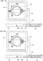
Fig. 16 is a sectional view showing a left side cross section of a functional unit in Embodiment 2 according to the present invention; -
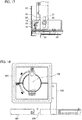
Fig. 17 is a sectional view showing a right side cross section of the functional unit in Embodiment 2 according to the present invention; -
Fig. 18 is a partially front view showing a part of a functional unit related to a prior art and shows a situation of an insertion and removal prevention plate and an insertion and removal handle's insertion opening when a wiring circuit breaker is in ON state; -
Fig. 19 is a front view showing a part of the functional unit related to the prior art and shows a situation where the insertion and removal handle is inserted into the insertion and removal handle's insertion opening when the wiring circuit breaker is in OFF state; -
Fig. 20 is a partially front view showing a situation where the insertion and removal handle is engaged with a partition plate from the state ofFig. 19 ; and -
Fig. 21 is a front view showing a part of the functional unit related to the prior art and shows the positional relationship of an insertion and removal prevention plate and the insertion and removal handle at the time when an operation handle is operated from the state ofFig. 20 . - Embodiments of the present invention will be described with reference to drawings; and the same reference numerals as those shown in the respective drawings represent identical or corresponding elements.
- Embodiment 1 in the present invention will be described by using
Fig. 1 to Fig. 15 .Fig. 1 is a front view of afunctional unit 10 which is housed on apartition plate 11 of a functional unit housing space provided in a motor control center main body panel and is equipped with a wiring circuit breaker and a functional unit interlock mechanism.Fig. 2 is a cross section taken along the line Z-Z ofFig. 1 .Fig. 3 is a cross section taken along the line Y1-Y1 ofFig. 1 .Fig. 4 is a cross section taken along the line Y2-Y2 ofFig. 1 . - The functional unit interlock mechanism is structured such that a left passing-
block joint 19 serving as a left passing-block body and a right passing-block joint 20 serving as a right passing-block body are attached to anoperation handle mechanism 17 having anoperation handle 18 which is for manually switching ON and OFF states of the wiring circuit breaker. Aguidance metal fitting 22 is arranged at a position passing through a guidanceelongated hole 21 provided on each of the left passing-block joint 19 and the right passing-block joint 20. Afront plate 12 having an insertion and removal handle's insertion opening 13 into which an insertion and removal handle is for being inserted into and removed from thefunctional unit 10, is attached on the front of thefunctional unit 10. The insertion and removal handle is accessible to the inside of thefunctional unit 10 from only the insertion and removal handle's insertion opening 13. An insertion andremoval prevention plate 14 serving as an insertion and removal prevention body slidably operable in the front horizontal direction is supported by a supportingmetal fitting 15 on the deep side of the insertion and removal handle'sinsertion opening 13. The supportingmetal fitting 15 is fixed to a fixingmetal fitting 16. The fixingmetal fitting 16 is fixed to abottom plate 23 of thefunctional unit 10. An insertion andremoval chamber casing 24 which is for protecting the inside of thefunctional unit 10 from the insertion and removal handle that is to be inserted into the insertion and removal handle'sinsertion opening 13, is attached on the further deep side; and theguidance metal fitting 22 is attached to the insertion andremoval chamber casing 24. -
Fig. 10 is a top view of afunctional unit 10 at the time when thefunctional unit 10 in which the wiring circuit breaker is in ON state is inserted from the outside of the control center main body panel.Fig. 11 is a sectional view taken along the line Y1-Y1 inFig. 10 .Fig. 12 is a sectional view taken along the line Y2-Y2 inFig. 10 .Fig. 13 is a top view of the functional unit in a state where thefunctional unit 10 is further inserted to the control center main body panel side from a stopped position of the above-mentioned insertion operation and acircuit connection section 25 on the control center main body panel side serving as the control center main body side and acircuit connection section 26 on the functional unit side are not completely engaged.Fig. 14 is a sectional view taken along the line Y1-Y1 inFig. 13 .Fig. 15 is a sectional view taken along the line Y2-Y2 ofFig. 13 . - As shown in
Fig. 1 , in a state where the wiring circuit breaker is in OFF state and the insertion andremoval prevention plate 14 is slid in the front left direction so that the insertion and removal handle'sinsertion opening 13 becomes an opened state, the insertion andremoval prevention plate 14 is located at a position where a descending route of the left passing-block joint 19 is blocked at a contact portion A shown inFig. 2 andFig. 3 ; and accordingly, even if the operation handle 18 is attempted to be rotated so that the wiring circuit breaker is in ON state, the left passing-block joint 19 is prevented from being moved by the insertion andremoval prevention plate 14 and the wiring circuit breaker cannot be in ON state. Additionally, by reducing the gap between the left passing-block joint 19 and the insertion andremoval prevention plate 14 shown in the contact portion A ofFig. 3 , if the operation handle 18 is attempted to be rotated, the left passing-block joint 19 immediately comes in contact with the insertion andremoval prevention plate 14; and thus, the amount of rotation of the operation handle 18 at the time when the wiring circuit breaker is attempted to be in ON state in a state where the insertion and removal handle'sinsertion opening 13 is opened and the insertion and removal handle is capable of being inserted into the insertion and removal handle'sinsertion opening 13. -
Fig. 5 is a front view of thefunctional unit 10 in a state where the wiring circuit breaker is in OFF state and the insertion andremoval prevention plate 14 is slid in the front right direction so that the insertion and removal handle'sinsertion opening 13 is closed; andFig. 6 shows a cross section taken along the line Z-Z ofFig. 5 . The insertion andremoval prevention plate 14 is located at a position where the descending route of the left passing-block joint 19 is avoided at a contact portion A shown inFig. 5 ; and thus, a mechanism is provided such that, in this state, if the operation handle 18 is rotated in a direction where the wiring circuit breaker is from OFF state to ON state as shown inFig. 7, Fig. 8 , andFig. 9 , the left passing-block joint 19 and the right passing-block joint 20 descend and the wiring circuit breaker is in ON state. - In this state, the left passing-block joint 19 is located at a position where a sliding route of the insertion and
removal prevention plate 14 is blocked and the left passing-block joint 19 and the insertion andremoval prevention plate 14 are arranged so as to reduce the gap therebetween, whereby even if the insertion andremoval prevention plate 14 is attempted to be slid in the front left direction so that the insertion and removal handle'sinsertion opening 13 is opened, the insertion andremoval prevention plate 14 immediately comes in contact with the left passing-block joint 19 and the insertion and removal handle can be prevented from being inserted into the insertion and removal handle'sinsertion opening 13 in a state where the wiring circuit breaker is in ON state. When it is desired to remove thefunctional unit 10 by putting the wiring circuit breaker from ON state to OFF state, thefunctional unit 10 can be removed by operating in a procedure opposite to the one described above. Moreover, the left passing-block joint 19 and the right passing-block joint 20 are stably operated by theguidance metal fitting 22. - Moreover, since the insertion and
removal prevention plate 14 covers more than half of the insertion and removal handle'sinsertion opening 13, it becomes more easily understandable than the prior art as to whether it is in an insertable and removable state or not. - As shown in
Fig. 10 ,Fig. 11, and Fig. 12 , it is structured such that when the wiring circuit breaker is in ON state and thefunctional unit 10 is inserted from the outside of the control center main body panel, the plate thickness surfaces of the left passing-block joint 19 and the right passing-block joint 20 come in contact with thepartition plate 11 so that the distance between thecircuit connection section 25 on the control center main body panel side and thecircuit connection section 26 on the functional unit side is equal to or larger than a necessary electrical insulation distance, that is, so that the insertion operation of thefunctional unit 10 is stopped at a position that satisfies equal to or more than this electrical insulation distance. - As shown in
Fig. 13, Fig. 14 , andFig. 15 , it is structured such that the lower ends of the left passing-block joint 19 and the right passing-block joint 20 come in contact with thepartition plate 11 and the operation handle 18 cannot be rotated after the lower ends come in contact with thepartition plate 11 so that the wiring circuit breaker is not in ON state in a state where the wiring circuit breaker is in OFF state, the functional unit is further inserted to the control center main body panel side from a position where the above-mentioned insertion operation is stopped, and thecircuit connection section 25 on the control center main body panel side and thecircuit connection section 26 on the functional unit side are not completely engaged. - As described above, in Embodiment 1, when the wiring circuit breaker is in OFF state, the insertion and removal handle is capable of being inserted into the insertion and removal handle's
insertion opening 13, the wiring circuit breaker cannot be in ON state, and the amount of rotation of the operation handle 18 at the time when the wiring circuit breaker is in ON state is suppressed. When the wiring circuit breaker is in ON state, the insertion and removal handle is prevented from being inserted into the insertion and removal handle'sinsertion opening 13. Furthermore, the left passing-block joint 19 and the right passing-block joint 20 are stably operated by theguidance metal fitting 22. Additionally, when thefunctional unit 10 is inserted from the outside of the control center main body panel in a state where the wiring circuit breaker is in ON state, the insertion operation of thefunctional unit 10 is stopped at the position where the distance between thecircuit connection section 25 on the control center main body panel side and thecircuit connection section 26 on the functional unit side is equal to or more than the necessary electrical insulation distance. In addition, the wiring circuit breaker is not in ON state in the state where the wiring circuit breaker is in OFF state, the functional unit is further inserted to the control center main body panel side from the position where the above-mentioned insertion operation is stopped, and thecircuit connection section 25 on the control center main body panel side and thecircuit connection section 26 on the functional unit side are not completely engaged. - Embodiment 2 of the present invention will be described by using
Fig. 16 andFig. 17 . Basic configurations and operational advantages are the same as the configurations and the operational advantages in the above-described Embodiment 1; however, as shown inFig. 16 , apad 27 is provided on apartition plate 11. - When in the state of
Fig. 13, Fig. 14 , andFig. 15 , as shown inFig. 3 and Fig. 4 , the left passing-block joint 19 descends by the distance between thepartition plate 11 and the lower end of the left passing-block joint 19 at the time when the wiring circuit breaker is in OFF, and the right passing-block joint 20 descends by the distance between thepartition plate 11 and the lower end of the right passing-block joint 20 at the time when the wiring circuit breaker is in OFF; and accordingly, the operation handle 18 rotates to some extent. As shown inFig. 16 andFig. 17 , by providing thepad 27 below the left passing-block joint 19 or the right passing-block joint 20, the lower end of the left passing-block joint 19 or the right passing-block joint 20 comes in contact with thepad 27 at an earlier stage; and thus, the amount of rotation of anoperation handle 18 can be suppressed. - As described above, in Embodiment 2, the amount of rotation of the operation handle 18 can be more suppressed as compared to the state of
Fig. 14 andFig. 15 , as shown inFig. 16 andFig. 17 . - The present invention can freely combine the respective embodiments and appropriately modify and/or omit the respective embodiments, within the scope of the present invention.
- 10 Functional unit, 11 Partition plate, 13 Insertion and removal handle's insertion opening, 14 Insertion and removal prevention plate, 17 Operation handle mechanism, 18 Operation handle, 19 Left passing-block joint, 20 Right passing-block joint, 25 Circuit connection section, 26 Circuit connection section, 27 Pad
Claims (7)
- An interlock mechanism of a functional unit, comprising:an insertion and removal handle's insertion opening which is provided in a functional unit and into which an insertion and removal handle that inserts and removes the functional unit is for being inserted, the functional unit being housed on a partition plate of a functional unit housing space in a control center and being equipped with a wiring circuit breaker; andan insertion and removal prevention body which prevents the insertion and removal handle from being inserted into the insertion and removal handle's insertion opening when an operation handle mechanism that turns ON and OFF the wiring circuit breaker is in ON state,wherein the interlock mechanism of the functional unit includes a passing-block body which is movably provided with respect to the insertion and removal prevention body in conjunction with the operation handle mechanism coupled to an operation handle that switches ON and OFF states of the wiring circuit breaker; andthe passing-block body is prevented from being moved according to the position of the insertion and removal prevention body.
- The interlock mechanism of the functional unit according to claim 1,
wherein the passing-block body is prevented from being moved by coming in contact with the insertion and removal prevention body with respect to the operation to the ON position direction of the operation handle when the operation handle is in OFF position state and the insertion and removal prevention body opens the insertion and removal handle's insertion opening. - The interlock mechanism of the functional unit according to claim 1,
wherein the passing-block body is released from movement prevention by the insertion and removal prevention body when the operation handle is in OFF position state and the insertion and removal prevention body is located at a position where the insertion and removal handle is prevented from being inserted. - The interlock mechanism of the functional unit according to claim 1,
wherein the passing-block body is released from movement prevention by the insertion and removal prevention body when the operation handle is in ON position state and the insertion and removal prevention body is located at a position where the insertion and removal handle is prevented from being inserted; and
the removal prevention body is movable in response to the operation to the OFF position of the operation handle. - The interlock mechanism of the functional unit according to claim 1,
wherein the passing-block body is prevented from being moved with a necessary electrical insulation distance between a circuit connection section on the control center main body side and a circuit connection section on the functional unit side by a side portion of the partition plate of the housing space when the operation handle is in ON position state and the functional unit is housed in the control center body. - The interlock mechanism of the functional unit according to claim 5,
wherein the passing-block body is released from movement prevention by the side portion of the partition plate of the housing space and is located on the upper side of the partition plate of the housing space until the circuit connection section on the control center body side and the circuit connection section on the functional unit side are connected and the operation handle is prevented from being moved to ON position when the operation handle is operated from ON position state to OFF position state. - The interlock mechanism of the functional unit according to claim 6,
further comprising a pad which is provided on the upper surface of the partition plate and is arranged between the partition plate and the passing-block body.
Applications Claiming Priority (1)
| Application Number | Priority Date | Filing Date | Title |
|---|---|---|---|
| PCT/JP2017/002996 WO2018138881A1 (en) | 2017-01-27 | 2017-01-27 | Function unit interlock mechanism |
Publications (3)
| Publication Number | Publication Date |
|---|---|
| EP3576235A1 true EP3576235A1 (en) | 2019-12-04 |
| EP3576235A4 EP3576235A4 (en) | 2020-01-08 |
| EP3576235B1 EP3576235B1 (en) | 2021-04-21 |
Family
ID=60265757
Family Applications (1)
| Application Number | Title | Priority Date | Filing Date |
|---|---|---|---|
| EP17894478.1A Active EP3576235B1 (en) | 2017-01-27 | 2017-01-27 | Function unit interlock mechanism |
Country Status (3)
| Country | Link |
|---|---|
| EP (1) | EP3576235B1 (en) |
| JP (1) | JP6227207B1 (en) |
| WO (1) | WO2018138881A1 (en) |
Family Cites Families (8)
| Publication number | Priority date | Publication date | Assignee | Title |
|---|---|---|---|---|
| US2921998A (en) * | 1958-05-02 | 1960-01-19 | Ite Circuit Breaker Ltd | Four position drawout circuit breaker |
| JPS5258433U (en) * | 1975-10-24 | 1977-04-27 | ||
| JPS61269604A (en) * | 1985-05-24 | 1986-11-29 | 株式会社日立製作所 | Input/output chain lock for breaker |
| JPH0638685B2 (en) * | 1987-09-24 | 1994-05-18 | 株式会社戸上電機製作所 | Closed switchboard |
| DE19948697A1 (en) * | 1999-09-30 | 2001-04-05 | Siemens Ag | Device insert with a base plate and a device holder that can be moved relative to it |
| DE102007017463A1 (en) * | 2007-04-10 | 2008-10-16 | Siemens Ag | Device drawer and control cabinet with a large number of device bays |
| KR101194385B1 (en) * | 2012-06-13 | 2012-10-24 | (주)서전기전 | A module type motor control center having a drawing position indicanting lever type device for drawing the unit thereof |
| JP6072998B1 (en) * | 2015-03-30 | 2017-02-01 | 三菱電機株式会社 | Control center |
-
2017
- 2017-01-27 JP JP2017536055A patent/JP6227207B1/en active Active
- 2017-01-27 EP EP17894478.1A patent/EP3576235B1/en active Active
- 2017-01-27 WO PCT/JP2017/002996 patent/WO2018138881A1/en not_active Ceased
Also Published As
| Publication number | Publication date |
|---|---|
| EP3576235B1 (en) | 2021-04-21 |
| WO2018138881A1 (en) | 2018-08-02 |
| JPWO2018138881A1 (en) | 2019-01-31 |
| JP6227207B1 (en) | 2017-11-08 |
| EP3576235A4 (en) | 2020-01-08 |
Similar Documents
| Publication | Publication Date | Title |
|---|---|---|
| EP2228878B1 (en) | Circuit breaker with apparatus for preventing withdrawing or inserting of carriage of circuit breaker | |
| US8854174B2 (en) | Fused disconnect switch with terminal opening cover | |
| JP6764295B2 (en) | Switch gear | |
| EP2372737A1 (en) | Electrical switching apparatus and close latch interlock assembly therefor | |
| US20060118397A1 (en) | Switching apparatus having a withdrawable-part rack and a lockable power circuit breaker | |
| JP4251092B2 (en) | Circuit breaker | |
| EP3576235A1 (en) | Function unit interlock mechanism | |
| US11189994B2 (en) | Circuit breaker | |
| JP2010104080A (en) | Fixing device for drawer-type device | |
| US6479770B2 (en) | Electrical switch | |
| CN104953496A (en) | Interlocking system used for shutters | |
| CN108987194A (en) | The safety device unit of circuit-breaker and circuit-breaker | |
| EP2088610B1 (en) | Containment and segregation compartment for switches and switch untis | |
| EP3280015B1 (en) | Control center | |
| CN101842949A (en) | switchboard | |
| JP4939869B2 (en) | Circuit breaker | |
| KR20100005162U (en) | Handle lock mechanism for mold cased circuit breaker | |
| KR200486587Y1 (en) | Transferring apparatus for vaccum circuit breaker | |
| JP4641008B2 (en) | Circuit breaker | |
| JP2007149586A (en) | Circuit breaker | |
| JP2014056768A (en) | Electromagnetic contactor | |
| EP2015334A2 (en) | Air cicuit breaker having simple detachable structure for over current relay | |
| KR102358058B1 (en) | Terminal cover for circuit breaker | |
| KR100631003B1 (en) | Auxiliary Cover Auto Trip Device of Circuit Breaker | |
| WO2020059001A1 (en) | Switchgear |
Legal Events
| Date | Code | Title | Description |
|---|---|---|---|
| STAA | Information on the status of an ep patent application or granted ep patent |
Free format text: STATUS: THE INTERNATIONAL PUBLICATION HAS BEEN MADE |
|
| PUAI | Public reference made under article 153(3) epc to a published international application that has entered the european phase |
Free format text: ORIGINAL CODE: 0009012 |
|
| STAA | Information on the status of an ep patent application or granted ep patent |
Free format text: STATUS: REQUEST FOR EXAMINATION WAS MADE |
|
| 17P | Request for examination filed |
Effective date: 20190702 |
|
| AK | Designated contracting states |
Kind code of ref document: A1 Designated state(s): AL AT BE BG CH CY CZ DE DK EE ES FI FR GB GR HR HU IE IS IT LI LT LU LV MC MK MT NL NO PL PT RO RS SE SI SK SM TR |
|
| AX | Request for extension of the european patent |
Extension state: BA ME |
|
| A4 | Supplementary search report drawn up and despatched |
Effective date: 20191205 |
|
| RIC1 | Information provided on ipc code assigned before grant |
Ipc: H02B 11/133 20060101AFI20191130BHEP Ipc: H02B 1/36 20060101ALI20191130BHEP |
|
| DAV | Request for validation of the european patent (deleted) | ||
| DAX | Request for extension of the european patent (deleted) | ||
| GRAP | Despatch of communication of intention to grant a patent |
Free format text: ORIGINAL CODE: EPIDOSNIGR1 |
|
| STAA | Information on the status of an ep patent application or granted ep patent |
Free format text: STATUS: GRANT OF PATENT IS INTENDED |
|
| INTG | Intention to grant announced |
Effective date: 20201103 |
|
| GRAS | Grant fee paid |
Free format text: ORIGINAL CODE: EPIDOSNIGR3 |
|
| GRAA | (expected) grant |
Free format text: ORIGINAL CODE: 0009210 |
|
| STAA | Information on the status of an ep patent application or granted ep patent |
Free format text: STATUS: THE PATENT HAS BEEN GRANTED |
|
| AK | Designated contracting states |
Kind code of ref document: B1 Designated state(s): AL AT BE BG CH CY CZ DE DK EE ES FI FR GB GR HR HU IE IS IT LI LT LU LV MC MK MT NL NO PL PT RO RS SE SI SK SM TR |
|
| REG | Reference to a national code |
Ref country code: GB Ref legal event code: FG4D |
|
| REG | Reference to a national code |
Ref country code: CH Ref legal event code: EP |
|
| REG | Reference to a national code |
Ref country code: DE Ref legal event code: R096 Ref document number: 602017037375 Country of ref document: DE Ref country code: IE Ref legal event code: FG4D |
|
| REG | Reference to a national code |
Ref country code: AT Ref legal event code: REF Ref document number: 1385640 Country of ref document: AT Kind code of ref document: T Effective date: 20210515 |
|
| REG | Reference to a national code |
Ref country code: LT Ref legal event code: MG9D |
|
| REG | Reference to a national code |
Ref country code: AT Ref legal event code: MK05 Ref document number: 1385640 Country of ref document: AT Kind code of ref document: T Effective date: 20210421 |
|
| REG | Reference to a national code |
Ref country code: NL Ref legal event code: MP Effective date: 20210421 |
|
| PG25 | Lapsed in a contracting state [announced via postgrant information from national office to epo] |
Ref country code: LT Free format text: LAPSE BECAUSE OF FAILURE TO SUBMIT A TRANSLATION OF THE DESCRIPTION OR TO PAY THE FEE WITHIN THE PRESCRIBED TIME-LIMIT Effective date: 20210421 Ref country code: FI Free format text: LAPSE BECAUSE OF FAILURE TO SUBMIT A TRANSLATION OF THE DESCRIPTION OR TO PAY THE FEE WITHIN THE PRESCRIBED TIME-LIMIT Effective date: 20210421 Ref country code: NL Free format text: LAPSE BECAUSE OF FAILURE TO SUBMIT A TRANSLATION OF THE DESCRIPTION OR TO PAY THE FEE WITHIN THE PRESCRIBED TIME-LIMIT Effective date: 20210421 Ref country code: AT Free format text: LAPSE BECAUSE OF FAILURE TO SUBMIT A TRANSLATION OF THE DESCRIPTION OR TO PAY THE FEE WITHIN THE PRESCRIBED TIME-LIMIT Effective date: 20210421 Ref country code: BG Free format text: LAPSE BECAUSE OF FAILURE TO SUBMIT A TRANSLATION OF THE DESCRIPTION OR TO PAY THE FEE WITHIN THE PRESCRIBED TIME-LIMIT Effective date: 20210721 Ref country code: HR Free format text: LAPSE BECAUSE OF FAILURE TO SUBMIT A TRANSLATION OF THE DESCRIPTION OR TO PAY THE FEE WITHIN THE PRESCRIBED TIME-LIMIT Effective date: 20210421 |
|
| PG25 | Lapsed in a contracting state [announced via postgrant information from national office to epo] |
Ref country code: NO Free format text: LAPSE BECAUSE OF FAILURE TO SUBMIT A TRANSLATION OF THE DESCRIPTION OR TO PAY THE FEE WITHIN THE PRESCRIBED TIME-LIMIT Effective date: 20210721 Ref country code: LV Free format text: LAPSE BECAUSE OF FAILURE TO SUBMIT A TRANSLATION OF THE DESCRIPTION OR TO PAY THE FEE WITHIN THE PRESCRIBED TIME-LIMIT Effective date: 20210421 Ref country code: PT Free format text: LAPSE BECAUSE OF FAILURE TO SUBMIT A TRANSLATION OF THE DESCRIPTION OR TO PAY THE FEE WITHIN THE PRESCRIBED TIME-LIMIT Effective date: 20210823 Ref country code: PL Free format text: LAPSE BECAUSE OF FAILURE TO SUBMIT A TRANSLATION OF THE DESCRIPTION OR TO PAY THE FEE WITHIN THE PRESCRIBED TIME-LIMIT Effective date: 20210421 Ref country code: RS Free format text: LAPSE BECAUSE OF FAILURE TO SUBMIT A TRANSLATION OF THE DESCRIPTION OR TO PAY THE FEE WITHIN THE PRESCRIBED TIME-LIMIT Effective date: 20210421 Ref country code: SE Free format text: LAPSE BECAUSE OF FAILURE TO SUBMIT A TRANSLATION OF THE DESCRIPTION OR TO PAY THE FEE WITHIN THE PRESCRIBED TIME-LIMIT Effective date: 20210421 Ref country code: IS Free format text: LAPSE BECAUSE OF FAILURE TO SUBMIT A TRANSLATION OF THE DESCRIPTION OR TO PAY THE FEE WITHIN THE PRESCRIBED TIME-LIMIT Effective date: 20210821 Ref country code: GR Free format text: LAPSE BECAUSE OF FAILURE TO SUBMIT A TRANSLATION OF THE DESCRIPTION OR TO PAY THE FEE WITHIN THE PRESCRIBED TIME-LIMIT Effective date: 20210722 |
|
| REG | Reference to a national code |
Ref country code: DE Ref legal event code: R097 Ref document number: 602017037375 Country of ref document: DE |
|
| PG25 | Lapsed in a contracting state [announced via postgrant information from national office to epo] |
Ref country code: RO Free format text: LAPSE BECAUSE OF FAILURE TO SUBMIT A TRANSLATION OF THE DESCRIPTION OR TO PAY THE FEE WITHIN THE PRESCRIBED TIME-LIMIT Effective date: 20210421 Ref country code: CZ Free format text: LAPSE BECAUSE OF FAILURE TO SUBMIT A TRANSLATION OF THE DESCRIPTION OR TO PAY THE FEE WITHIN THE PRESCRIBED TIME-LIMIT Effective date: 20210421 Ref country code: DK Free format text: LAPSE BECAUSE OF FAILURE TO SUBMIT A TRANSLATION OF THE DESCRIPTION OR TO PAY THE FEE WITHIN THE PRESCRIBED TIME-LIMIT Effective date: 20210421 Ref country code: SK Free format text: LAPSE BECAUSE OF FAILURE TO SUBMIT A TRANSLATION OF THE DESCRIPTION OR TO PAY THE FEE WITHIN THE PRESCRIBED TIME-LIMIT Effective date: 20210421 Ref country code: SM Free format text: LAPSE BECAUSE OF FAILURE TO SUBMIT A TRANSLATION OF THE DESCRIPTION OR TO PAY THE FEE WITHIN THE PRESCRIBED TIME-LIMIT Effective date: 20210421 Ref country code: EE Free format text: LAPSE BECAUSE OF FAILURE TO SUBMIT A TRANSLATION OF THE DESCRIPTION OR TO PAY THE FEE WITHIN THE PRESCRIBED TIME-LIMIT Effective date: 20210421 Ref country code: ES Free format text: LAPSE BECAUSE OF FAILURE TO SUBMIT A TRANSLATION OF THE DESCRIPTION OR TO PAY THE FEE WITHIN THE PRESCRIBED TIME-LIMIT Effective date: 20210421 |
|
| PLBE | No opposition filed within time limit |
Free format text: ORIGINAL CODE: 0009261 |
|
| STAA | Information on the status of an ep patent application or granted ep patent |
Free format text: STATUS: NO OPPOSITION FILED WITHIN TIME LIMIT |
|
| 26N | No opposition filed |
Effective date: 20220124 |
|
| PG25 | Lapsed in a contracting state [announced via postgrant information from national office to epo] |
Ref country code: IS Free format text: LAPSE BECAUSE OF FAILURE TO SUBMIT A TRANSLATION OF THE DESCRIPTION OR TO PAY THE FEE WITHIN THE PRESCRIBED TIME-LIMIT Effective date: 20210821 Ref country code: AL Free format text: LAPSE BECAUSE OF FAILURE TO SUBMIT A TRANSLATION OF THE DESCRIPTION OR TO PAY THE FEE WITHIN THE PRESCRIBED TIME-LIMIT Effective date: 20210421 |
|
| PG25 | Lapsed in a contracting state [announced via postgrant information from national office to epo] |
Ref country code: IT Free format text: LAPSE BECAUSE OF FAILURE TO SUBMIT A TRANSLATION OF THE DESCRIPTION OR TO PAY THE FEE WITHIN THE PRESCRIBED TIME-LIMIT Effective date: 20210421 |
|
| PG25 | Lapsed in a contracting state [announced via postgrant information from national office to epo] |
Ref country code: MC Free format text: LAPSE BECAUSE OF FAILURE TO SUBMIT A TRANSLATION OF THE DESCRIPTION OR TO PAY THE FEE WITHIN THE PRESCRIBED TIME-LIMIT Effective date: 20210421 |
|
| REG | Reference to a national code |
Ref country code: CH Ref legal event code: PL |
|
| GBPC | Gb: european patent ceased through non-payment of renewal fee |
Effective date: 20220127 |
|
| REG | Reference to a national code |
Ref country code: BE Ref legal event code: MM Effective date: 20220131 |
|
| PG25 | Lapsed in a contracting state [announced via postgrant information from national office to epo] |
Ref country code: LU Free format text: LAPSE BECAUSE OF NON-PAYMENT OF DUE FEES Effective date: 20220127 Ref country code: GB Free format text: LAPSE BECAUSE OF NON-PAYMENT OF DUE FEES Effective date: 20220127 |
|
| PG25 | Lapsed in a contracting state [announced via postgrant information from national office to epo] |
Ref country code: FR Free format text: LAPSE BECAUSE OF NON-PAYMENT OF DUE FEES Effective date: 20220131 Ref country code: BE Free format text: LAPSE BECAUSE OF NON-PAYMENT OF DUE FEES Effective date: 20220131 |
|
| PG25 | Lapsed in a contracting state [announced via postgrant information from national office to epo] |
Ref country code: LI Free format text: LAPSE BECAUSE OF NON-PAYMENT OF DUE FEES Effective date: 20220131 Ref country code: CH Free format text: LAPSE BECAUSE OF NON-PAYMENT OF DUE FEES Effective date: 20220131 |
|
| PG25 | Lapsed in a contracting state [announced via postgrant information from national office to epo] |
Ref country code: IE Free format text: LAPSE BECAUSE OF NON-PAYMENT OF DUE FEES Effective date: 20220127 |
|
| P01 | Opt-out of the competence of the unified patent court (upc) registered |
Effective date: 20230512 |
|
| PG25 | Lapsed in a contracting state [announced via postgrant information from national office to epo] |
Ref country code: MK Free format text: LAPSE BECAUSE OF FAILURE TO SUBMIT A TRANSLATION OF THE DESCRIPTION OR TO PAY THE FEE WITHIN THE PRESCRIBED TIME-LIMIT Effective date: 20210421 Ref country code: CY Free format text: LAPSE BECAUSE OF FAILURE TO SUBMIT A TRANSLATION OF THE DESCRIPTION OR TO PAY THE FEE WITHIN THE PRESCRIBED TIME-LIMIT Effective date: 20210421 |
|
| PG25 | Lapsed in a contracting state [announced via postgrant information from national office to epo] |
Ref country code: HU Free format text: LAPSE BECAUSE OF FAILURE TO SUBMIT A TRANSLATION OF THE DESCRIPTION OR TO PAY THE FEE WITHIN THE PRESCRIBED TIME-LIMIT; INVALID AB INITIO Effective date: 20170127 |
|
| PG25 | Lapsed in a contracting state [announced via postgrant information from national office to epo] |
Ref country code: TR Free format text: LAPSE BECAUSE OF FAILURE TO SUBMIT A TRANSLATION OF THE DESCRIPTION OR TO PAY THE FEE WITHIN THE PRESCRIBED TIME-LIMIT Effective date: 20210421 |
|
| PG25 | Lapsed in a contracting state [announced via postgrant information from national office to epo] |
Ref country code: MT Free format text: LAPSE BECAUSE OF FAILURE TO SUBMIT A TRANSLATION OF THE DESCRIPTION OR TO PAY THE FEE WITHIN THE PRESCRIBED TIME-LIMIT Effective date: 20210421 |
|
| REG | Reference to a national code |
Ref country code: DE Ref legal event code: R084 Ref document number: 602017037375 Country of ref document: DE |
|
| PGFP | Annual fee paid to national office [announced via postgrant information from national office to epo] |
Ref country code: DE Payment date: 20251203 Year of fee payment: 10 |