EP3576116A1 - Magnetic component and switch power supply device - Google Patents
Magnetic component and switch power supply device Download PDFInfo
- Publication number
- EP3576116A1 EP3576116A1 EP19154662.1A EP19154662A EP3576116A1 EP 3576116 A1 EP3576116 A1 EP 3576116A1 EP 19154662 A EP19154662 A EP 19154662A EP 3576116 A1 EP3576116 A1 EP 3576116A1
- Authority
- EP
- European Patent Office
- Prior art keywords
- winding
- column
- primary
- columns
- magnetic component
- Prior art date
- Legal status (The legal status is an assumption and is not a legal conclusion. Google has not performed a legal analysis and makes no representation as to the accuracy of the status listed.)
- Granted
Links
Images




Classifications
-
- H—ELECTRICITY
- H01—ELECTRIC ELEMENTS
- H01F—MAGNETS; INDUCTANCES; TRANSFORMERS; SELECTION OF MATERIALS FOR THEIR MAGNETIC PROPERTIES
- H01F27/00—Details of transformers or inductances, in general
- H01F27/28—Coils; Windings; Conductive connections
- H01F27/32—Insulating of coils, windings, or parts thereof
-
- H—ELECTRICITY
- H01—ELECTRIC ELEMENTS
- H01F—MAGNETS; INDUCTANCES; TRANSFORMERS; SELECTION OF MATERIALS FOR THEIR MAGNETIC PROPERTIES
- H01F38/00—Adaptations of transformers or inductances for specific applications or functions
-
- H—ELECTRICITY
- H01—ELECTRIC ELEMENTS
- H01F—MAGNETS; INDUCTANCES; TRANSFORMERS; SELECTION OF MATERIALS FOR THEIR MAGNETIC PROPERTIES
- H01F27/00—Details of transformers or inductances, in general
- H01F27/24—Magnetic cores
-
- H—ELECTRICITY
- H01—ELECTRIC ELEMENTS
- H01F—MAGNETS; INDUCTANCES; TRANSFORMERS; SELECTION OF MATERIALS FOR THEIR MAGNETIC PROPERTIES
- H01F27/00—Details of transformers or inductances, in general
- H01F27/28—Coils; Windings; Conductive connections
-
- H—ELECTRICITY
- H01—ELECTRIC ELEMENTS
- H01F—MAGNETS; INDUCTANCES; TRANSFORMERS; SELECTION OF MATERIALS FOR THEIR MAGNETIC PROPERTIES
- H01F27/00—Details of transformers or inductances, in general
- H01F27/28—Coils; Windings; Conductive connections
- H01F27/2823—Wires
-
- H—ELECTRICITY
- H01—ELECTRIC ELEMENTS
- H01F—MAGNETS; INDUCTANCES; TRANSFORMERS; SELECTION OF MATERIALS FOR THEIR MAGNETIC PROPERTIES
- H01F27/00—Details of transformers or inductances, in general
- H01F27/28—Coils; Windings; Conductive connections
- H01F27/29—Terminals; Tapping arrangements for signal inductances
-
- H—ELECTRICITY
- H01—ELECTRIC ELEMENTS
- H01F—MAGNETS; INDUCTANCES; TRANSFORMERS; SELECTION OF MATERIALS FOR THEIR MAGNETIC PROPERTIES
- H01F27/00—Details of transformers or inductances, in general
- H01F27/40—Structural association with built-in electric component, e.g. fuse
-
- H—ELECTRICITY
- H02—GENERATION; CONVERSION OR DISTRIBUTION OF ELECTRIC POWER
- H02M—APPARATUS FOR CONVERSION BETWEEN AC AND AC, BETWEEN AC AND DC, OR BETWEEN DC AND DC, AND FOR USE WITH MAINS OR SIMILAR POWER SUPPLY SYSTEMS; CONVERSION OF DC OR AC INPUT POWER INTO SURGE OUTPUT POWER; CONTROL OR REGULATION THEREOF
- H02M3/00—Conversion of DC power input into DC power output
- H02M3/22—Conversion of DC power input into DC power output with intermediate conversion into AC
- H02M3/24—Conversion of DC power input into DC power output with intermediate conversion into AC by static converters
- H02M3/28—Conversion of DC power input into DC power output with intermediate conversion into AC by static converters using discharge tubes with control electrode or semiconductor devices with control electrode to produce the intermediate AC
- H02M3/285—Single converters with a plurality of output stages connected in parallel
-
- H—ELECTRICITY
- H02—GENERATION; CONVERSION OR DISTRIBUTION OF ELECTRIC POWER
- H02M—APPARATUS FOR CONVERSION BETWEEN AC AND AC, BETWEEN AC AND DC, OR BETWEEN DC AND DC, AND FOR USE WITH MAINS OR SIMILAR POWER SUPPLY SYSTEMS; CONVERSION OF DC OR AC INPUT POWER INTO SURGE OUTPUT POWER; CONTROL OR REGULATION THEREOF
- H02M3/00—Conversion of DC power input into DC power output
- H02M3/22—Conversion of DC power input into DC power output with intermediate conversion into AC
- H02M3/24—Conversion of DC power input into DC power output with intermediate conversion into AC by static converters
- H02M3/28—Conversion of DC power input into DC power output with intermediate conversion into AC by static converters using discharge tubes with control electrode or semiconductor devices with control electrode to produce the intermediate AC
- H02M3/325—Conversion of DC power input into DC power output with intermediate conversion into AC by static converters using discharge tubes with control electrode or semiconductor devices with control electrode to produce the intermediate AC using devices of a triode or a transistor type requiring continuous application of a control signal
- H02M3/335—Conversion of DC power input into DC power output with intermediate conversion into AC by static converters using discharge tubes with control electrode or semiconductor devices with control electrode to produce the intermediate AC using devices of a triode or a transistor type requiring continuous application of a control signal using semiconductor devices only
- H02M3/33569—Conversion of DC power input into DC power output with intermediate conversion into AC by static converters using discharge tubes with control electrode or semiconductor devices with control electrode to produce the intermediate AC using devices of a triode or a transistor type requiring continuous application of a control signal using semiconductor devices only having several active switching elements
- H02M3/33576—Conversion of DC power input into DC power output with intermediate conversion into AC by static converters using discharge tubes with control electrode or semiconductor devices with control electrode to produce the intermediate AC using devices of a triode or a transistor type requiring continuous application of a control signal using semiconductor devices only having several active switching elements having at least one active switching element at the secondary side of an isolation transformer
-
- H—ELECTRICITY
- H01—ELECTRIC ELEMENTS
- H01F—MAGNETS; INDUCTANCES; TRANSFORMERS; SELECTION OF MATERIALS FOR THEIR MAGNETIC PROPERTIES
- H01F27/00—Details of transformers or inductances, in general
- H01F27/40—Structural association with built-in electric component, e.g. fuse
- H01F2027/408—Association with diode or rectifier
-
- H—ELECTRICITY
- H01—ELECTRIC ELEMENTS
- H01F—MAGNETS; INDUCTANCES; TRANSFORMERS; SELECTION OF MATERIALS FOR THEIR MAGNETIC PROPERTIES
- H01F38/00—Adaptations of transformers or inductances for specific applications or functions
- H01F2038/006—Adaptations of transformers or inductances for specific applications or functions matrix transformer consisting of several interconnected individual transformers working as a whole
-
- H—ELECTRICITY
- H02—GENERATION; CONVERSION OR DISTRIBUTION OF ELECTRIC POWER
- H02M—APPARATUS FOR CONVERSION BETWEEN AC AND AC, BETWEEN AC AND DC, OR BETWEEN DC AND DC, AND FOR USE WITH MAINS OR SIMILAR POWER SUPPLY SYSTEMS; CONVERSION OF DC OR AC INPUT POWER INTO SURGE OUTPUT POWER; CONTROL OR REGULATION THEREOF
- H02M1/00—Details of apparatus for conversion
- H02M1/0064—Magnetic structures combining different functions, e.g. storage, filtering or transformation
-
- H—ELECTRICITY
- H02—GENERATION; CONVERSION OR DISTRIBUTION OF ELECTRIC POWER
- H02M—APPARATUS FOR CONVERSION BETWEEN AC AND AC, BETWEEN AC AND DC, OR BETWEEN DC AND DC, AND FOR USE WITH MAINS OR SIMILAR POWER SUPPLY SYSTEMS; CONVERSION OF DC OR AC INPUT POWER INTO SURGE OUTPUT POWER; CONTROL OR REGULATION THEREOF
- H02M1/00—Details of apparatus for conversion
- H02M1/0067—Converter structures employing plural converter units, other than for parallel operation of the units on a single load
- H02M1/0074—Plural converter units whose inputs are connected in series
-
- H—ELECTRICITY
- H02—GENERATION; CONVERSION OR DISTRIBUTION OF ELECTRIC POWER
- H02M—APPARATUS FOR CONVERSION BETWEEN AC AND AC, BETWEEN AC AND DC, OR BETWEEN DC AND DC, AND FOR USE WITH MAINS OR SIMILAR POWER SUPPLY SYSTEMS; CONVERSION OF DC OR AC INPUT POWER INTO SURGE OUTPUT POWER; CONTROL OR REGULATION THEREOF
- H02M3/00—Conversion of DC power input into DC power output
- H02M3/22—Conversion of DC power input into DC power output with intermediate conversion into AC
- H02M3/24—Conversion of DC power input into DC power output with intermediate conversion into AC by static converters
- H02M3/28—Conversion of DC power input into DC power output with intermediate conversion into AC by static converters using discharge tubes with control electrode or semiconductor devices with control electrode to produce the intermediate AC
- H02M3/325—Conversion of DC power input into DC power output with intermediate conversion into AC by static converters using discharge tubes with control electrode or semiconductor devices with control electrode to produce the intermediate AC using devices of a triode or a transistor type requiring continuous application of a control signal
- H02M3/335—Conversion of DC power input into DC power output with intermediate conversion into AC by static converters using discharge tubes with control electrode or semiconductor devices with control electrode to produce the intermediate AC using devices of a triode or a transistor type requiring continuous application of a control signal using semiconductor devices only
- H02M3/33569—Conversion of DC power input into DC power output with intermediate conversion into AC by static converters using discharge tubes with control electrode or semiconductor devices with control electrode to produce the intermediate AC using devices of a triode or a transistor type requiring continuous application of a control signal using semiconductor devices only having several active switching elements
Definitions
- the present disclosure relates to a magnetic component and a switch power supply device.
- a turn ratio of primary and secondary sides (N p :N s1 :N s2 ) of the transformer of the LLC resonant circuit is 18:1:1, which can be divided into three sub-transformers of 6:1:1 having primary windings connected in series, and secondary windings connected in parallel. In such way, the same current flows through the primary windings, and the secondary windings are connected in parallel to form a tripled current output.
- the structure of the plurality of sub-transformers can have an effect of parallelizing transmission power, but the plurality of sub-transformers are designed discretely and complicated in structure.
- the key and difficult point of designing and developing the magnetic component is always how to optimize shape of the magnetic core, reduce size and loss of the magnetic core.
- An aspect of the present disclosure is to overcome the deficiency of the prior art, and provides a magnetic component with small size and low loss.
- Another aspect of the present disclosure is to provide a switch power supply device, and optimize design of the magnetic component therein.
- the present disclosure provides a magnetic component including a magnetic core
- the magnetic core includes a first winding column, a second winding column, a third winding column, a first side column, a second side column, and a first cover plate and a second cover plate which are disposed opposite to each other
- the second winding column is disposed between the first winding column and the third winding column
- the first side column and the second side column are disposed respectively outside the first winding column and the third winding column
- the first cover plate and the second cover plate are disposed respectively above and below the first winding column, the second winding column, the third winding column, the first side column and the second side column to form a closed magnetic flux loop
- a magnetic flux of the first winding column and a magnetic flux of the third winding column have a first direction
- a magnetic flux of the second winding column has a second direction opposite to the first direction
- the present disclosure further provides a magnetic component, including: a magnetic core including at least one side column, a first cover plate and a second cover plate which are disposed opposite to each other, wherein at least three winding columns are sequentially arranged, the first cover plate and the second cover plate are disposed respectively above and below the at least three winding columns and the at least one side column to form a closed magnetic flux loop; and at least three windings wound on the at least three winding columns, respectively; wherein magnetic flux direction of the middle winding column in adjacent three winding columns is opposite to magnetic fluxes direction of the other two winding columns in adjacent three winding columns.
- the present disclosure further provides a switch power supply device having a magnetic component as described above, including:
- the present disclosure can effectively reduce the size and loss of the magnetic component.
- electrically couple used in the text, it may refer to that two or more components are directly physically or electrically contacted, or are indirectly physically or electrically contacted.
- electrically couple in series used in the text, it may refer to that two or more components are directly connected in series to be physically or electrically contacted, or are indirectly connected in series to be physically or electrically contacted, and “electrically couple in parallel” may refer to that two or more components are directly connected in parallel to be physically or electrically contacted, or are indirectly connected in parallel to be physically or electrically contacted.
- FIG. 1A illustrates a switch power supply device 10 of the present disclosure.
- the switch power supply device 10 includes a primary circuit 11, an isolation conversion module 12 and a secondary circuit 13.
- the primary circuit 11 receives an input voltage V in , and converts the input voltage V in into a primary voltage.
- a circuit topology of the primary circuit 11 may be a half-bridge, and also may be a full-bridge or other topology.
- the isolation conversion module 12 converts the primary voltage into a secondary voltage, and may includes a first transformer T xa , a second transformer T xb and a third transformer T xc .
- the first transformer T xa includes a first primary winding N pa , a first secondary winding N sla and a second secondary winding N s2a , and a first end of the first primary winding N pa is electrically coupled to one end of the primary circuit 11;
- the second transformer T xb includes a second primary winding N pb , a third secondary winding N s1b and a fourth secondary winding N s2b , and a first end of the second primary winding N pb is electrically coupled to a second end of the first primary winding N pa ;
- the third transformer T xc includes a third primary winding N pc , a fifth secondary winding N s1c and a sixth secondary winding N s2c , a first end of the third primary
- the secondary circuit 13 converts the secondary voltage into an output voltage V o .
- the first secondary winding N sla is connected to the second secondary winding N s2a in series, a first end of the first secondary winding N sla is electrically coupled to a first output terminal P 1 via a first switch transistor S 1 , a second end of the second secondary winding N s2a is electrically coupled to the first output terminal P 1 via a second switch transistor S 2 , and a second end of the first secondary winding N sla and a first end of the second secondary winding N s2a are connected and electrically coupled to a second output terminal P 2 .
- the third secondary winding N s1b is connected to the fourth secondary winding N s2b in series, a first end of the third secondary winding N s1b is electrically coupled to the first output terminal P 1 via a third switch transistor S 3 , a second end of the fourth secondary winding N s2b is electrically coupled to the first output terminal P 1 via a fourth switch transistor S 4 , and a second end of the third secondary winding N s1b and a first end of the fourth secondary winding N s2b are connected and electrically coupled to the second output terminal P 2 .
- the fifth secondary winding N s1c is connected to the sixth secondary winding N s2c in series, a first end of the fifth secondary winding N s1c is electrically coupled to the first output terminal P 1 via a fifth switch transistor S 5 , a second end of the sixth secondary winding N s2 is electrically coupled to the first output terminal P 1 via a sixth switch transistor S 6 , and a second end of the fifth secondary winding N s1c and a first end of the sixth secondary winding N s2 are connected and electrically coupled to the second output terminal P 2 .
- connection manner of the first primary winding N pa , the second primary winding N pb and the third primary winding N pc in the present disclosure may be directly connected in series, as shown in FIG. 1A ; also may be indirectly coupled in series, as shown in FIG. 1B ; also may be directly connected in parallel, as shown in FIG. 1C ; also may be indirectly coupled in parallel, as shown in FIG. 1D .
- These connection manners are not used as a limit to the present disclosure.
- the circuit topology of the input terminal is not limited to the half-bridge or full-bridge shown in the drawings, and also may be other circuit structure.
- the circuit topology of the output terminal may not be limited to half-wave rectification shown in the drawings, and also may be other manners such as full-wave rectification.
- the switch power supply device of the present disclosure may receive an input voltage, for example, an input voltage V in in a range from 300V to 450V, preferably, for example, an input voltage V in in a range from 410V to 450V.
- the switch power supply device of the present disclosure may also receive an input voltage, for example, an input voltage V in in a range from 36V to 72V. They are also not used as a limit to the present disclosure.
- the magnetic component of the present disclosure is introduced below.
- FIG. 2 is a magnetic component in one embodiment of the present disclosure, and illustrates, for example, a schematic diagram of structure of an array transformer 20 consisting of a plurality of transformers of the isolation conversion module 12 and connection of windings thereof in the switch power supply device shown in FIG. 1A .
- the transformer 20 includes a magnetic core 21, and the magnetic core 21 includes a first winding column 211, a second winding column 212, a third winding column 213, a first side column 214, a second side column 215, a first cover plate 216 and a second cover plate 217 opposite to each other.
- the second winding column 212 is between the first winding column 211 and the third winding column 213, the first side column 214 and the second side column 215 are respectively outside the first winding column 211 and the third winding column 213, and the first cover plate 216 and the second cover plate 217 are disposed respectively above and below the first winding column 211, the second winding column 212, the third winding column 213, the first side column 214 and the second side column 215 to form a closed magnetic flux loop.
- a magnetic flux ⁇ a of the first winding column 211 and a magnetic flux ⁇ c of the third winding column 213 have a first direction
- a magnetic flux ⁇ b of the second winding column 212 has a second direction opposite to the first direction.
- the winding N pa , the winding N pb and the winding N pc are connected in series, when a current i p flows through the windings, the magnetic flux ⁇ a of the first winding column 211 and the magnetic flux ⁇ c the third winding column 213 have the same direction, which is shown downwardly in the drawing, and is opposite to the direction of the magnetic flux ⁇ b of the second winding column 212, which is shown upwardly in the drawing.
- the first primary winding N pa , the first secondary winding N sla and the second secondary winding N s2a are wound on the first winding column 211 to form the first transformer T xa
- the second primary winding N pb , the third secondary winding N s1b and the fourth secondary winding N s2b are wound on the second winding column 212 to form the second transformer T xb
- the third primary winding N pc , the fifth secondary winding N s1c and the sixth secondary winding N s2c are wound on the third winding column 213 to form the third transformer T xc .
- first primary winding N pa , the second primary winding N pb and the third primary winding N pc are connected in series.
- currents flowing through the first primary winding N pa , the second primary winding N pb and the third primary winding N pc have the same magnitude and phase.
- FIG. 2 does not show the secondary windings.
- the winding columns also may not have secondary windings, and it is used as an inductor.
- a size of the magnetic core may be effectively reduced by integrating the three transformers into the same magnetic component.
- loss of the magnetic core may be effectively reduced by configuring that magnetic flux direction of the middle winding column in adjacent three winding columns is opposite to magnetic fluxes direction of the other two winding columns in adjacent three winding columns.
- the first primary winding N pa , the second primary winding N pb and the third primary winding N pc may be PCB windings or triple insulated wire windings.
- the number of turns of the primary windings is the same.
- the first secondary winding N s1a , the second secondary winding N s2a , the third secondary winding N s1b , the fourth secondary winding N s2b , the fifth secondary winding N s1c and the sixth secondary winding N s2c may be PCB windings or copper sheet windings.
- the number of turns of each secondary winding may be, for example, one.
- FIG. 3A is a stereoscopic structure diagram of the first magnetic core structure in the present disclosure
- FIG. 3B illustrates an exploded diagram of the magnetic core structure shown in FIG. 3A
- a magnetic core structure 30 of the present disclosure includes a magnetic core 31, besides including a first winding column 311, a second winding column 312, a third winding column 313, a first side column 314 and a second side column 315, it further includes a first cover plate 316 and a second cover plate 317 opposite to each other.
- the first cover plate 316 and the second cover plate 317 are disposed respectively above and below the first winding column 311, the second winding column 312, the third winding column 313, the first side column 314 and the second side column 315 to form a closed magnetic flux loop.
- FIG. 3C illustrates a stereoscopic structure diagram of the magnetic core structure after omitting the first cover plate shown in FIG. 3A
- FIG. 3D illustrates a top view of the magnetic core structure shown in FIG. 3C
- the three winding columns such as, the first winding column 311, the second winding column 312 and the third winding column 313, of the magnetic core structure are sequentially arranged along a horizontal line, and the first side column 314 and the second side column 315 are disposed on both ends of the horizontal line, respectively.
- the magnetic core structure 30 also may only include a single side column which is on one side of the horizontal line.
- FIG. 3E illustrates a top view of the second magnetic core structure of the present disclosure, and it differs from the magnetic core structure shown in FIG. 3D in that the first winding column 311, the second winding column 312 and the third winding column 313 are dislocated at a certain level in relative positions, and a straight line can contact or penetrate through the first winding column 311, and the common straight line also contacts with or penetrates through the second winding column 312, and the common straight line also contacts with or penetrates through the third winding column313, as shown by an imaginary line L in the drawing.
- FIG. 3F illustrates current directions of the windings of the magnetic core structure shown in FIG. 3D , wherein current directions I 1 and I 3 of the first winding column 311 and the third winding column 313 are clockwise directions, and a current direction I 2 of the second winding column 312 is an counterclockwise direction.
- FIG. 3G illustrates that the primary winding of the magnetic core structure shown in FIG. 3D can be formed of only one winding which is wound in a " ⁇ shape".
- a current direction I of the winding surrounding the first winding column 311 and the third winding column 313 is a clockwise direction
- a current direction I of the winding surrounding the second winding column 312 is an counterclockwise direction.
- FIG. 4A is a stereoscopic structure diagram of the third magnetic core structure 40 in the present disclosure. Besides including a first winding column 411, a second winding column 412, a third winding column 413, a first side column 414 and a second side column 415, the magnetic core structure 40 further includes a first cover plate (not shown) and a second cover plate 417 opposite to each other. The first cover plate and the second cover plate 417 are disposed respectively above and below the first winding column 411, the second winding column 412, the third winding column 413, the first side column 414 and the second side column 415 to form a closed magnetic flux loop.
- FIG. 1 is a stereoscopic structure diagram of the third magnetic core structure 40 in the present disclosure.
- the magnetic core structure 40 further includes a first cover plate (not shown) and a second cover plate 417 opposite to each other.
- the first cover plate and the second cover plate 417 are disposed respectively above and below the first winding column 411, the second winding column
- FIG. 4A illustrates a stereoscopic structure diagram of the magnetic core structure 40 after omitting the first cover plate
- FIG. 4B illustrates a top view of the magnetic core structure shown in FIG. 4A , wherein the three winding columns, such as, the first winding column 411, the second winding column 412 and the third winding column 413, of the magnetic core structure are sequentially arranged along a horizontal line, and the first side column 414 and the second side column 415 are disposed on the same side of the horizontal line.
- FIG. 4C illustrates current directions of the windings of the magnetic core structure shown in FIG. 4A .
- Current directions I 1 and I 3 of the first winding column 411 and the third winding column 413 are clockwise directions
- a current direction I 2 of the second winding column 412 is an counterclockwise direction.
- FIG. 5A is a stereoscopic structure diagram of the fourth magnetic core structure in the present disclosure.
- the magnetic core structure 50 further includes a first cover plate (not shown) and a second cover plate 517 opposite to each other.
- the first cover plate and the second cover plate 517 are disposed respectively above and below the first winding column 511, the second winding column 512, the third winding column 513, the first side column 514 and the second side column 515 to form a closed magnetic flux loop.
- FIG. 1 is a stereoscopic structure diagram of the fourth magnetic core structure in the present disclosure.
- the magnetic core structure 50 further includes a first cover plate (not shown) and a second cover plate 517 opposite to each other.
- the first cover plate and the second cover plate 517 are disposed respectively above and below the first winding column 511, the second winding column 512, the third winding column 513, the first side column 514 and the second side column 515 to form a closed magnetic flux loop.
- FIG. 5A illustrates a stereoscopic structure diagram of the magnetic core structure after omitting the first cover plate
- FIG. 5B illustrates a top view of the magnetic core structure shown in FIG. 5A , wherein the three winding columns, such as, the first winding column 511, the second winding column 512 and the third winding column 513, of the magnetic core structure are sequentially arranged along a horizontal line, and the first side column 514 and the second side column 515 are disposed on different sides of the horizontal line, respectively.
- FIG. 5C illustrates current directions of the windings of the magnetic core structure shown in FIG. 5A .
- Current directions of I 1 and I 3 of the first winding column 511 and the third winding column 513 are clockwise directions
- a current direction I 2 of the second winding column 512 is an counterclockwise direction.
- the magnetic core structures shown in FIGS. 3A-3G , 4A-4C and 5A-5C may be used to form the magnetic component shown in FIG. 2 , i.e., a transformer integrated magnetic component (e.g., an array transformer), wherein the primary windings may be a PCB winding, triple insulated wire winding or other type of winding, and the secondary windings may be a PCB winding, a copper sheet winding or other type of winding.
- two secondary windings are wound on each winding column of the magnetic component shown in FIG. 2 , but the disclosure is not limited thereto. In other embodiment, only one secondary winding is wound on each winding column.
- the magnetic component 20 shown in FIG. 2 also may not have secondary windings, and at this time, it may be used as an inductor, i.e., forming an inductor integrated magnetic component.
- FIG. 2 only illustrates a transformer integrated magnetic component with three sub-transformers integrated onto one iron core.
- the present disclosure also may have other variations, such as, a transformer integrated magnetic component formed by integrating more sub-transformers, or such as, an inductor integrated magnetic component only formed by integrating more primary windings (i.e., without secondary windings). They are not used as a limit to the present disclosure.
- FIG. 6A illustrates a structure extending to a plurality of sub-transformers integrated onto one iron core on the basis of FIG. 2 , such as, a transformer integrated magnetic component 60 consisting of four sub-transformers shown in FIG. 6A .
- the transformer integrated magnetic component 60 includes a magnetic core 61, and the magnetic core 61 includes a first side column 615, a first winding column 611, a second winding column 612, a third winding column 613, a fourth winding column 614 and a second side column 616 sequentially arranged in adjacent, and further includes a first cover plate 617 and a second cover plate 618 opposite to each other.
- the first cover plate 617 and the second cover plate 618 are disposed respectively above and below the first winding column 611, the second winding column 612, the third winding column 613, the fourth winding column 614, the first side column 615 and the second side column 616 to form a closed magnetic flux loop.
- Magnetic flux direction of the middle winding column in adjacent three winding columns is opposite to magnetic fluxes direction of the other two winding columns in adjacent three winding columns.
- a magnetic flux ⁇ b of the middle winding column (i.e., the second winding column 612) has a direction opposite to that of magnetic fluxes ⁇ a and ⁇ c of the first winding column 611 and the third winding column 613 on both sides
- a magnetic flux ⁇ c of the middle winding column (i.e., the third winding column 613) has a direction opposite to that of magnetic fluxes ⁇ b and ⁇ d of the second winding column 612 and the fourth winding column 614 on both sides.
- FIG. 6B illustrates a stereoscopic structure diagram of the magnetic core structure after omitting the first cover plate.
- FIG. 6C illustrates a top view of the magnetic core structure shown in FIG. 6B .
- the four winding columns, such as, the first winding column 611, the second winding column 612, the third winding column 613 and the fourth winding column 614, of the magnetic core 61 are sequentially arranged along a horizontal line, and the first side column 615 and the second side column 616 are disposed on both ends of the horizontal line, respectively.
- FIG. 6D illustrates current directions of the windings of the magnetic core structure shown in FIG.
- the primary windings may be PCB or triple insulated wire or other forms of windings
- the secondary windings may be PCB or copper sheet or other forms of windings. It also may not have secondary windings, and at this time, it may be used as an inductor.
- FIGS. 7A and 7B which illustrate a structure of another magnetic component 70 in another embodiment of the present disclosure, and illustrate an embodiment of adding an inductance winding column on the left side of the first side column on the basis of FIG. 2 .
- An inductor winding N r is wound on the inductance winding column to form a resonant inductor Lr of the LLC circuit in FIG. 1A .
- the embodiment is a magnetic integration manner in which the resonant inductor and the transformer share side columns.
- the magnetic component 70 includes a magnetic core 71
- the magnetic core 71 includes an inductance winding column 718, a first side column 714, a first winding column 711, a second winding column 712, a third winding column 713 and a second side column 715 sequentially arranged in adjacent, and further includes a first cover plate 716 and a second cover plate 717 opposite to each other.
- the first cover plate 716 and the second cover plate 717 are disposed respectively above and below the first winding column 711, the second winding column 712, the third winding column 713, the inductance winding column 718, the first side column 714 and the second side column 715 to form a closed magnetic flux loop.
- FIG. 7B illustrates a stereoscopic structure diagram of the magnetic core structure after omitting the first cover plate
- FIG. 7C illustrates a top view of the magnetic core structure shown in FIG. 7B .
- the three winding columns, such as, the first winding column 711, the second winding column 712 and the third winding column 713, of the magnetic core 71 are sequentially arranged along a horizontal line, the first side column 714 and the second side column 715 are disposed on both ends of the horizontal line, respectively, and the inductance winding column 718 is outside one end of the first side column 714. In another embodiment, the inductance winding column 718 also may be outside one end of the second side column 715.
- FIG. 7D illustrates current directions of the windings of the magnetic core structure shown in FIG. 7B .
- Current directions I 1 and I 3 of the first winding column 711 and the third winding column 713 are clockwise directions
- a current direction I 2 of the second winding column 712 is an counterclockwise direction
- a current direction of the winding corresponding to the inductance winding column may be a clockwise direction, and also may be an counterclockwise direction.
- the primary windings may be PCB or triple insulated wire or other forms of windings
- the secondary windings may be PCB or copper sheet or other forms of windings. It also may not have secondary windings, and it is used as an inductor.
- the present disclosure can effectively reduce a size of the magnetic component by integrating a multipath inductor or transformer into the same magnetic component.
- loss of the magnetic core is effectively reduced.
- the shape of the winding columns illustrated above is not limited to a cylinder shown in the drawings, and also may be various shapes, such as, a polygon, a racetrack, an oval and the like. Moreover, in the present disclosure, cross sections of these winding columns are substantially the same, which means a difference within 5%, especially within 3%. As for the same magnetic flux, it means that a difference of magnetic fluxes is no more than 5%, especially no more than 3%.
- inner sides of the first side column and the second side column also may be provided with outer contour corresponding parts (not shown) corresponding to outer contours of the corresponding winding columns, such as, arc concave parts corresponding to outer contours of the cylindrical winding columns.
- An outer side of the first side column or the second side column also may be provided with an inductance outer contour corresponding part corresponding to an outer contour of the corresponding inductance winding column (e.g., please refer to FIGS. 7B and 7C ).
Landscapes
- Engineering & Computer Science (AREA)
- Power Engineering (AREA)
- Coils Of Transformers For General Uses (AREA)
- Dc-Dc Converters (AREA)
- Coils Or Transformers For Communication (AREA)
Abstract
Description
- The present application is based upon and claims priority to Chinese Patent Application No.
201810522699.6, filed on May 28, 2018 - The present disclosure relates to a magnetic component and a switch power supply device.
- In application of low voltage and large current output, it requires to design the transformer in array, and divide it into a plurality of sub-transformer units for combination. For example, in a 3kW server power supply with an input voltage 430V and an output voltage 12V, a turn ratio of primary and secondary sides (Np:Ns1:Ns2) of the transformer of the LLC resonant circuit is 18:1:1, which can be divided into three sub-transformers of 6:1:1 having primary windings connected in series, and secondary windings connected in parallel. In such way, the same current flows through the primary windings, and the secondary windings are connected in parallel to form a tripled current output. The structure of the plurality of sub-transformers can have an effect of parallelizing transmission power, but the plurality of sub-transformers are designed discretely and complicated in structure. The key and difficult point of designing and developing the magnetic component is always how to optimize shape of the magnetic core, reduce size and loss of the magnetic core.
- An aspect of the present disclosure is to overcome the deficiency of the prior art, and provides a magnetic component with small size and low loss.
- Another aspect of the present disclosure is to provide a switch power supply device, and optimize design of the magnetic component therein.
- In order to achieve the above object, the present disclosure provides a magnetic component including a magnetic core, the magnetic core includes a first winding column, a second winding column, a third winding column, a first side column, a second side column, and a first cover plate and a second cover plate which are disposed opposite to each other, wherein the second winding column is disposed between the first winding column and the third winding column, the first side column and the second side column are disposed respectively outside the first winding column and the third winding column, the first cover plate and the second cover plate are disposed respectively above and below the first winding column, the second winding column, the third winding column, the first side column and the second side column to form a closed magnetic flux loop; wherein a magnetic flux of the first winding column and a magnetic flux of the third winding column have a first direction, and a magnetic flux of the second winding column has a second direction opposite to the first direction; in a plane where the magnetic core is located, a straight line contacts with or penetrates through the first winding column, and the common straight line also contacts with or penetrates through the second winding column, and the common straight line also contacts with or penetrates through the third winding column.
- In order to achieve the above object, the present disclosure further provides a magnetic component, including: a magnetic core including at least one side column, a first cover plate and a second cover plate which are disposed opposite to each other, wherein at least three winding columns are sequentially arranged, the first cover plate and the second cover plate are disposed respectively above and below the at least three winding columns and the at least one side column to form a closed magnetic flux loop; and at least three windings wound on the at least three winding columns, respectively; wherein magnetic flux direction of the middle winding column in adjacent three winding columns is opposite to magnetic fluxes direction of the other two winding columns in adjacent three winding columns.
- In order to achieve the above object, the present disclosure further provides a switch power supply device having a magnetic component as described above, including:
- a primary circuit for receiving an input voltage, and converting the input voltage into a primary voltage;
- an isolation conversion module for converting the primary voltage into a secondary voltage, and including: a first transformer including a first primary winding, a first secondary winding and a second secondary winding; a second transformer including a second primary winding, a third secondary winding and a fourth secondary winding; and a third transformer including a third primary winding, a fifth secondary winding and a sixth secondary winding;
- a secondary circuit for converting the secondary voltage into an output voltage;
- wherein the first primary winding, the first secondary winding and the second secondary winding are wound on the first winding column, the second primary winding, the third secondary winding and the fourth secondary winding are wound on the second winding column, and the third primary winding, the fifth secondary winding and the sixth secondary winding are wound on the third winding column.
- By integrating multiple inductors or transformers into the same magnetic component, magnetic flux direction of the middle winding column in adjacent three winding columns is opposite to magnetic fluxes direction of the other two winding columns in adjacent three winding columns, the present disclosure can effectively reduce the size and loss of the magnetic component.
- Additional aspects and advantages of the present disclosure will be partially explained below, and will become partially apparent from the explanation, or may be obtained from practice of the present disclosure.
- Other features and advantages of the present disclosure will become more apparent by explicitly describing exemplary embodiments with reference to the drawings.
-
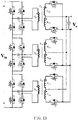
FIG. 1A illustrates a structure diagram of a switch power supply device in one embodiment of the present disclosure, wherein primary windings of a plurality of transformers in an isolation conversion module of the switch power supply device are in a manner of being directly connected in series. -
FIG. 1B illustrates a structure diagram of a switch power supply device in another embodiment of the present disclosure, wherein primary windings of a plurality of transformers in an isolation conversion module of the switch power supply device are in a manner of being indirectly coupled in series. -
FIG. 1C illustrates a structure diagram of a switch power supply device in another embodiment of the present disclosure, wherein primary windings of a plurality of transformers in an isolation conversion module of the switch power supply device are in a manner of being directly connected in parallel. -
FIG. 1D illustrates a structure diagram of a switch power supply device in another embodiment of the present disclosure, wherein primary windings of a plurality of transformers in an isolation conversion module of the switch power supply device are in a manner of being indirectly coupled in parallel. -
FIG. 2 illustrates a connection diagram of windings of the plurality of transformers in the isolation conversion module of the switch power supply device shown inFIG. 1A . -
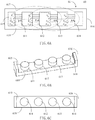
FIG. 3A illustrates a stereoscopic assembly diagram of the first magnetic core structure of the magnetic component of the present disclosure, wherein the magnetic core structure includes a first winding column, a second winding column, a third winding column, a first side column, a second side column, a first cover plate and a second cover plate. -
FIG. 3B illustrates a stereoscopic exploded diagram of the magnetic core structure shown inFIG. 3A . -
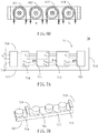
FIG. 3C illustrates a stereoscopic diagram of the magnetic core structure without the first cover plate shown inFIG. 3A . -
FIG. 3D illustrates a top view of the magnetic core structure shown inFIG. 3C . -
FIG. 3E illustrates a top view of the second magnetic core structure of the magnetic component of the present disclosure, wherein in a plane where the magnetic core is located, a common straight line can contact or penestrate through the three winding columns simultaneously. -
FIG. 3F illustrates current directions corresponding to the three winding columns in the magnetic core structure shown inFIG. 3D . -
FIG. 3G illustrates a schematic diagram in which the magnetic core structure shown inFIG. 3D can be connected in a "∞" shape by one winding. -
FIG. 4A illustrates a stereoscopic diagram of the third magnetic core structure of the magnetic component of the present disclosure, wherein the two side columns of the magnetic core structure are not on the same horizontal line as the three winding columns, and the two side columns are on the same side. -
FIG. 4B illustrates a top view of the magnetic core structure shown inFIG. 4A . -
FIG. 4C illustrates current directions corresponding to the three winding columns of the magnetic core structure shown inFIG. 4A . -
FIG. 5A illustrates a stereoscopic diagram of the fourth magnetic core structure of the magnetic component of the present disclosure, wherein the two side columns of the magnetic core structure are not on the same horizontal line as the three winding columns, and the two side columns are on different sides. -
FIG. 5B illustrates a top view of the magnetic core structure shown inFIG. 5A . -
FIG. 5C illustrates current directions corresponding to the three winding columns of the magnetic core structure shown inFIG. 5A . -
FIG. 6A illustrates a schematic diagram of structure of a transformer and connection of windings in another embodiment of the present disclosure, wherein the number of the winding columns is four. -
FIG. 6B illustrates a stereoscopic diagram of the magnetic core structure without the first cover plate of the transformer shown inFIG. 6A . -
FIG. 6C illustrates a top view of the magnetic core structure shown inFIG. 6B . -
FIG. 6D illustrates current directions corresponding to the four winding columns of the magnetic core structure shown inFIG. 6B . -
FIG. 7A illustrates a schematic diagram of the magnetic component adding one inductance winding column on the basis ofFIG. 2 . -
FIG. 7B illustrates a stereoscopic diagram of the magnetic core structure without the first cover plate in the magnetic component shown inFIG. 7A . -
FIG. 7C illustrates a top view of the magnetic core structure shown inFIG. 7B . -
FIG. 7D illustrates current directions corresponding to the three winding columns of the magnetic core structure shown inFIG. 7B . - Now exemplary embodiments are fully described with reference to the drawings. However, the exemplary embodiments can be implemented in various forms, and shall not be understood as a limit to the embodiments described here. On the contrary, these embodiments are provided to allow the present disclosure to be comprehensive and complete, and concept of the exemplary embodiments is fully conveyed to one skilled in the art. The same reference signs in the drawings represent the same or similar structure, so the detailed explanations are omitted.
- When elements/components/the like described and/or illustrated here are introduced, expressions of "one", "first", "the", and "at least one" are used to represent one or more elements/components/the like. The terms "include", "include" and "have" are used to represent an open meaning of including, and refer to that except the listed elements/components/the like, additional elements/components/the like also may exist. The embodiments may use relative expressions, such as, "upper" or "lower", to describe a relative relationship of one assembly relative to another assembly. It can be understood that if the illustrated device reverses to turn upside down, the assembly on an "upper" side will become an assembly on a "lower" side. In addition, the terms "first", "second" and the like in the claims are only used as signs, and do not limit the number of objects.
- As for "electrically couple" used in the text, it may refer to that two or more components are directly physically or electrically contacted, or are indirectly physically or electrically contacted. As for "electrically couple in series" used in the text, it may refer to that two or more components are directly connected in series to be physically or electrically contacted, or are indirectly connected in series to be physically or electrically contacted, and "electrically couple in parallel" may refer to that two or more components are directly connected in parallel to be physically or electrically contacted, or are indirectly connected in parallel to be physically or electrically contacted.
- Please refer to
FIG. 1A , which illustrates a switchpower supply device 10 of the present disclosure. The switchpower supply device 10 includes aprimary circuit 11, anisolation conversion module 12 and asecondary circuit 13. - The
primary circuit 11 receives an input voltage Vin, and converts the input voltage Vin into a primary voltage. A circuit topology of theprimary circuit 11 may be a half-bridge, and also may be a full-bridge or other topology. - The
isolation conversion module 12 converts the primary voltage into a secondary voltage, and may includes a first transformer Txa, a second transformer Txb and a third transformer Txc. The first transformer Txa includes a first primary winding Npa, a first secondary winding Nsla and a second secondary winding Ns2a, and a first end of the first primary winding Npa is electrically coupled to one end of theprimary circuit 11; the second transformer Txb includes a second primary winding Npb, a third secondary winding Ns1b and a fourth secondary winding Ns2b, and a first end of the second primary winding Npb is electrically coupled to a second end of the first primary winding Npa; the third transformer Txc includes a third primary winding Npc, a fifth secondary winding Ns1c and a sixth secondary winding Ns2c, a first end of the third primary winding Npc is electrically coupled to a second end of the second primary winding Npb, and a second end of the third primary winding Npc is electrically coupled to the other end of theprimary circuit 11. - The
secondary circuit 13 converts the secondary voltage into an output voltage Vo. - For example, in the embodiment shown in
FIG. 1A , the first secondary winding Nsla is connected to the second secondary winding Ns2a in series, a first end of the first secondary winding Nsla is electrically coupled to a first output terminal P1 via a first switch transistor S1, a second end of the second secondary winding Ns2a is electrically coupled to the first output terminal P1 via a second switch transistor S2, and a second end of the first secondary winding Nsla and a first end of the second secondary winding Ns2a are connected and electrically coupled to a second output terminal P2. - The third secondary winding Ns1b is connected to the fourth secondary winding Ns2b in series, a first end of the third secondary winding Ns1b is electrically coupled to the first output terminal P1 via a third switch transistor S3, a second end of the fourth secondary winding Ns2b is electrically coupled to the first output terminal P1 via a fourth switch transistor S4, and a second end of the third secondary winding Ns1b and a first end of the fourth secondary winding Ns2b are connected and electrically coupled to the second output terminal P2.
- The fifth secondary winding Ns1c is connected to the sixth secondary winding Ns2c in series, a first end of the fifth secondary winding Ns1c is electrically coupled to the first output terminal P1 via a fifth switch transistor S5, a second end of the sixth secondary winding Ns2 is electrically coupled to the first output terminal P1 via a sixth switch transistor S6, and a second end of the fifth secondary winding Ns1c and a first end of the sixth secondary winding Ns2 are connected and electrically coupled to the second output terminal P2.
- However, it can be understood that a connection manner of the first primary winding Npa, the second primary winding Npb and the third primary winding Npc in the present disclosure may be directly connected in series, as shown in
FIG. 1A ; also may be indirectly coupled in series, as shown inFIG. 1B ; also may be directly connected in parallel, as shown inFIG. 1C ; also may be indirectly coupled in parallel, as shown inFIG. 1D . These connection manners are not used as a limit to the present disclosure. - Furthermore, it can be understood that the circuit topology of the input terminal is not limited to the half-bridge or full-bridge shown in the drawings, and also may be other circuit structure. The circuit topology of the output terminal may not be limited to half-wave rectification shown in the drawings, and also may be other manners such as full-wave rectification. In addition, the switch power supply device of the present disclosure may receive an input voltage, for example, an input voltage Vin in a range from 300V to 450V, preferably, for example, an input voltage Vin in a range from 410V to 450V. Furthermore, the switch power supply device of the present disclosure may also receive an input voltage, for example, an input voltage Vin in a range from 36V to 72V. They are also not used as a limit to the present disclosure.
- The magnetic component of the present disclosure is introduced below.
- Please refer to
FIG. 2 , which is a magnetic component in one embodiment of the present disclosure, and illustrates, for example, a schematic diagram of structure of anarray transformer 20 consisting of a plurality of transformers of theisolation conversion module 12 and connection of windings thereof in the switch power supply device shown inFIG. 1A . In this embodiment, thetransformer 20 includes amagnetic core 21, and themagnetic core 21 includes a first windingcolumn 211, a second windingcolumn 212, a third windingcolumn 213, afirst side column 214, asecond side column 215, afirst cover plate 216 and asecond cover plate 217 opposite to each other. The second windingcolumn 212 is between the first windingcolumn 211 and the third windingcolumn 213, thefirst side column 214 and thesecond side column 215 are respectively outside the first windingcolumn 211 and the third windingcolumn 213, and thefirst cover plate 216 and thesecond cover plate 217 are disposed respectively above and below the first windingcolumn 211, the second windingcolumn 212, the third windingcolumn 213, thefirst side column 214 and thesecond side column 215 to form a closed magnetic flux loop. A magnetic flux Φa of the first windingcolumn 211 and a magnetic flux Φc of the third windingcolumn 213 have a first direction, and a magnetic flux Φb of the second windingcolumn 212 has a second direction opposite to the first direction. For example, inFIG. 2 , the winding Npa, the winding Npb and the winding Npc are connected in series, when a current ip flows through the windings, the magnetic flux Φa of the first windingcolumn 211 and the magnetic flux Φc the third windingcolumn 213 have the same direction, which is shown downwardly in the drawing, and is opposite to the direction of the magnetic flux Φb of the second windingcolumn 212, which is shown upwardly in the drawing. - Referring to
FIG. 1A , the first primary winding Npa, the first secondary winding Nsla and the second secondary winding Ns2a are wound on the first windingcolumn 211 to form the first transformer Txa, the second primary winding Npb, the third secondary winding Ns1b and the fourth secondary winding Ns2b are wound on the second windingcolumn 212 to form the second transformer Txb, and the third primary winding Npc, the fifth secondary winding Ns1c and the sixth secondary winding Ns2c are wound on the third windingcolumn 213 to form the third transformer Txc. Moreover, the first primary winding Npa, the second primary winding Npb and the third primary winding Npc are connected in series. Preferably, currents flowing through the first primary winding Npa, the second primary winding Npb and the third primary winding Npc have the same magnitude and phase.FIG. 2 does not show the secondary windings. In other embodiments, the winding columns also may not have secondary windings, and it is used as an inductor. - As compared to three discrete transformers, a size of the magnetic core may be effectively reduced by integrating the three transformers into the same magnetic component. Moreover, loss of the magnetic core may be effectively reduced by configuring that magnetic flux direction of the middle winding column in adjacent three winding columns is opposite to magnetic fluxes direction of the other two winding columns in adjacent three winding columns.
- According to the embodiment of the present disclosure, the first primary winding Npa, the second primary winding Npb and the third primary winding Npc, for example, may be PCB windings or triple insulated wire windings. Preferably, the number of turns of the primary windings is the same.
- According to the embodiment of the present disclosure, the first secondary winding Ns1a, the second secondary winding Ns2a, the third secondary winding Ns1b, the fourth secondary winding Ns2b, the fifth secondary winding Ns1c and the sixth secondary winding Ns2c, for example, may be PCB windings or copper sheet windings. Preferably, the number of turns of each secondary winding may be, for example, one.
- Referring to
FIGS. 3A-3G ,FIG. 3A is a stereoscopic structure diagram of the first magnetic core structure in the present disclosure, andFIG. 3B illustrates an exploded diagram of the magnetic core structure shown inFIG. 3A . As shown inFIGS. 3A-3B , amagnetic core structure 30 of the present disclosure includes amagnetic core 31, besides including a first windingcolumn 311, a second windingcolumn 312, a third windingcolumn 313, afirst side column 314 and asecond side column 315, it further includes afirst cover plate 316 and asecond cover plate 317 opposite to each other. Thefirst cover plate 316 and thesecond cover plate 317 are disposed respectively above and below the first windingcolumn 311, the second windingcolumn 312, the third windingcolumn 313, thefirst side column 314 and thesecond side column 315 to form a closed magnetic flux loop. - In order to clearly show the three winding columns and the two side columns,
FIG. 3C illustrates a stereoscopic structure diagram of the magnetic core structure after omitting the first cover plate shown inFIG. 3A , andFIG. 3D illustrates a top view of the magnetic core structure shown inFIG. 3C . Preferably, the three winding columns, such as, the first windingcolumn 311, the second windingcolumn 312 and the third windingcolumn 313, of the magnetic core structure are sequentially arranged along a horizontal line, and thefirst side column 314 and thesecond side column 315 are disposed on both ends of the horizontal line, respectively. However, according to other embodiment of the present disclosure, themagnetic core structure 30 also may only include a single side column which is on one side of the horizontal line. -
FIG. 3E illustrates a top view of the second magnetic core structure of the present disclosure, and it differs from the magnetic core structure shown inFIG. 3D in that the first windingcolumn 311, the second windingcolumn 312 and the third windingcolumn 313 are dislocated at a certain level in relative positions, and a straight line can contact or penetrate through the first windingcolumn 311, and the common straight line also contacts with or penetrates through the second windingcolumn 312, and the common straight line also contacts with or penetrates through the third winding column313, as shown by an imaginary line L in the drawing. -
FIG. 3F illustrates current directions of the windings of the magnetic core structure shown inFIG. 3D , wherein current directions I1 and I3 of the first windingcolumn 311 and the third windingcolumn 313 are clockwise directions, and a current direction I2 of the second windingcolumn 312 is an counterclockwise direction. -
FIG. 3G illustrates that the primary winding of the magnetic core structure shown inFIG. 3D can be formed of only one winding which is wound in a "∞ shape". A current direction I of the winding surrounding the first windingcolumn 311 and the third windingcolumn 313 is a clockwise direction, and a current direction I of the winding surrounding the second windingcolumn 312 is an counterclockwise direction. - Referring to
FIGS. 4A, 4B and 4C, FIG. 4A is a stereoscopic structure diagram of the thirdmagnetic core structure 40 in the present disclosure. Besides including a first windingcolumn 411, a second windingcolumn 412, a third windingcolumn 413, afirst side column 414 and asecond side column 415, themagnetic core structure 40 further includes a first cover plate (not shown) and asecond cover plate 417 opposite to each other. The first cover plate and thesecond cover plate 417 are disposed respectively above and below the first windingcolumn 411, the second windingcolumn 412, the third windingcolumn 413, thefirst side column 414 and thesecond side column 415 to form a closed magnetic flux loop.FIG. 4A illustrates a stereoscopic structure diagram of themagnetic core structure 40 after omitting the first cover plate, andFIG. 4B illustrates a top view of the magnetic core structure shown inFIG. 4A , wherein the three winding columns, such as, the first windingcolumn 411, the second windingcolumn 412 and the third windingcolumn 413, of the magnetic core structure are sequentially arranged along a horizontal line, and thefirst side column 414 and thesecond side column 415 are disposed on the same side of the horizontal line.FIG. 4C illustrates current directions of the windings of the magnetic core structure shown inFIG. 4A . Current directions I1 and I3 of the first windingcolumn 411 and the third windingcolumn 413 are clockwise directions, and a current direction I2 of the second windingcolumn 412 is an counterclockwise direction. - Referring to
FIGS. 5A, 5B and 5C, FIG. 5A is a stereoscopic structure diagram of the fourth magnetic core structure in the present disclosure. Besides including a first windingcolumn 511, a second windingcolumn 512, a third windingcolumn 513, afirst side column 514 and asecond side column 515, themagnetic core structure 50 further includes a first cover plate (not shown) and asecond cover plate 517 opposite to each other. The first cover plate and thesecond cover plate 517 are disposed respectively above and below the first windingcolumn 511, the second windingcolumn 512, the third windingcolumn 513, thefirst side column 514 and thesecond side column 515 to form a closed magnetic flux loop.FIG. 5A illustrates a stereoscopic structure diagram of the magnetic core structure after omitting the first cover plate, andFIG. 5B illustrates a top view of the magnetic core structure shown inFIG. 5A , wherein the three winding columns, such as, the first windingcolumn 511, the second windingcolumn 512 and the third windingcolumn 513, of the magnetic core structure are sequentially arranged along a horizontal line, and thefirst side column 514 and thesecond side column 515 are disposed on different sides of the horizontal line, respectively.FIG. 5C illustrates current directions of the windings of the magnetic core structure shown inFIG. 5A . Current directions of I1 and I3 of the first windingcolumn 511 and the third windingcolumn 513 are clockwise directions, and a current direction I2 of the second windingcolumn 512 is an counterclockwise direction. - In one embodiment of the present disclosure, the magnetic core structures shown in
FIGS. 3A-3G ,4A-4C and5A-5C may be used to form the magnetic component shown inFIG. 2 , i.e., a transformer integrated magnetic component (e.g., an array transformer), wherein the primary windings may be a PCB winding, triple insulated wire winding or other type of winding, and the secondary windings may be a PCB winding, a copper sheet winding or other type of winding. Moreover, two secondary windings are wound on each winding column of the magnetic component shown inFIG. 2 , but the disclosure is not limited thereto. In other embodiment, only one secondary winding is wound on each winding column. - In other embodiment of the present disclosure, the
magnetic component 20 shown inFIG. 2 also may not have secondary windings, and at this time, it may be used as an inductor, i.e., forming an inductor integrated magnetic component. - Although
FIG. 2 only illustrates a transformer integrated magnetic component with three sub-transformers integrated onto one iron core. However, it can be understood that the present disclosure also may have other variations, such as, a transformer integrated magnetic component formed by integrating more sub-transformers, or such as, an inductor integrated magnetic component only formed by integrating more primary windings (i.e., without secondary windings). They are not used as a limit to the present disclosure. - Referring to
FIGS. 6A, 6B, 6C and6D ,FIG. 6A illustrates a structure extending to a plurality of sub-transformers integrated onto one iron core on the basis ofFIG. 2 , such as, a transformer integratedmagnetic component 60 consisting of four sub-transformers shown inFIG. 6A . The transformer integratedmagnetic component 60 includes amagnetic core 61, and themagnetic core 61 includes afirst side column 615, a first windingcolumn 611, a second windingcolumn 612, a third windingcolumn 613, a fourth windingcolumn 614 and asecond side column 616 sequentially arranged in adjacent, and further includes afirst cover plate 617 and asecond cover plate 618 opposite to each other. Thefirst cover plate 617 and thesecond cover plate 618 are disposed respectively above and below the first windingcolumn 611, the second windingcolumn 612, the third windingcolumn 613, the fourth windingcolumn 614, thefirst side column 615 and thesecond side column 616 to form a closed magnetic flux loop. Magnetic flux direction of the middle winding column in adjacent three winding columns is opposite to magnetic fluxes direction of the other two winding columns in adjacent three winding columns. For example, in the adjacent first windingcolumn 611, the second windingcolumn 612 and the third windingcolumn 613, a magnetic flux Φb of the middle winding column (i.e., the second winding column 612) has a direction opposite to that of magnetic fluxes Φa and Φc of the first windingcolumn 611 and the third windingcolumn 613 on both sides, and in the adjacent second windingcolumn 612, the third windingcolumn 613 and the fourth windingcolumn 614, a magnetic flux Φc of the middle winding column (i.e., the third winding column 613) has a direction opposite to that of magnetic fluxes Φb and Φd of the second windingcolumn 612 and the fourth windingcolumn 614 on both sides. -
FIG. 6B illustrates a stereoscopic structure diagram of the magnetic core structure after omitting the first cover plate.FIG. 6C illustrates a top view of the magnetic core structure shown inFIG. 6B . The four winding columns, such as, the first windingcolumn 611, the second windingcolumn 612, the third windingcolumn 613 and the fourth windingcolumn 614, of themagnetic core 61 are sequentially arranged along a horizontal line, and thefirst side column 615 and thesecond side column 616 are disposed on both ends of the horizontal line, respectively.FIG. 6D illustrates current directions of the windings of the magnetic core structure shown inFIG. 6B , wherein current directions I1 and I3 of the first windingcolumn 611 and the third windingcolumn 613 are clockwise directions, and current directions I2 and I4 of the second windingcolumn 612 and the fourth windingcolumn 614 are counterclockwise directions. Similarly, in the embodiments shown inFIGS. 6A-6D , the primary windings may be PCB or triple insulated wire or other forms of windings, and the secondary windings may be PCB or copper sheet or other forms of windings. It also may not have secondary windings, and at this time, it may be used as an inductor. - Referring to
FIGS. 7A and 7B , which illustrate a structure of anothermagnetic component 70 in another embodiment of the present disclosure, and illustrate an embodiment of adding an inductance winding column on the left side of the first side column on the basis ofFIG. 2 . An inductor winding Nr is wound on the inductance winding column to form a resonant inductor Lr of the LLC circuit inFIG. 1A . The embodiment is a magnetic integration manner in which the resonant inductor and the transformer share side columns. In this embodiment, themagnetic component 70 includes amagnetic core 71, and themagnetic core 71 includes aninductance winding column 718, afirst side column 714, a first windingcolumn 711, a second windingcolumn 712, a third windingcolumn 713 and asecond side column 715 sequentially arranged in adjacent, and further includes afirst cover plate 716 and asecond cover plate 717 opposite to each other. Thefirst cover plate 716 and thesecond cover plate 717 are disposed respectively above and below the first windingcolumn 711, the second windingcolumn 712, the third windingcolumn 713, theinductance winding column 718, thefirst side column 714 and thesecond side column 715 to form a closed magnetic flux loop. Moreover, directions of magnetic fluxes Φa and Φc on the first windingcolumn 711 and the third windingcolumn 713 are downwardly, a direction of a magnetic flux Φb on the second windingcolumn 712 is upwardly, and a direction of a magnetic flux on theinductance winding column 718 may be upwardly, and also may be downwardly.FIG. 7B illustrates a stereoscopic structure diagram of the magnetic core structure after omitting the first cover plate, andFIG. 7C illustrates a top view of the magnetic core structure shown inFIG. 7B . The three winding columns, such as, the first windingcolumn 711, the second windingcolumn 712 and the third windingcolumn 713, of themagnetic core 71 are sequentially arranged along a horizontal line, thefirst side column 714 and thesecond side column 715 are disposed on both ends of the horizontal line, respectively, and theinductance winding column 718 is outside one end of thefirst side column 714. In another embodiment, theinductance winding column 718 also may be outside one end of thesecond side column 715.FIG. 7D illustrates current directions of the windings of the magnetic core structure shown inFIG. 7B . Current directions I1 and I3 of the first windingcolumn 711 and the third windingcolumn 713 are clockwise directions, a current direction I2 of the second windingcolumn 712 is an counterclockwise direction, and a current direction of the winding corresponding to the inductance winding column may be a clockwise direction, and also may be an counterclockwise direction. Similarly, in the embodiments shown inFIGS. 7A-7D , the primary windings may be PCB or triple insulated wire or other forms of windings, and the secondary windings may be PCB or copper sheet or other forms of windings. It also may not have secondary windings, and it is used as an inductor. - The present disclosure can effectively reduce a size of the magnetic component by integrating a multipath inductor or transformer into the same magnetic component. In addition, by configuring that magnetic flux direction of the middle winding column in adjacent three winding columns is opposite to magnetic fluxes direction of the other two winding columns in adjacent three winding columns, loss of the magnetic core is effectively reduced.
- In the present disclosure, the shape of the winding columns illustrated above is not limited to a cylinder shown in the drawings, and also may be various shapes, such as, a polygon, a racetrack, an oval and the like. Moreover, in the present disclosure, cross sections of these winding columns are substantially the same, which means a difference within 5%, especially within 3%. As for the same magnetic flux, it means that a difference of magnetic fluxes is no more than 5%, especially no more than 3%.
- Furthermore, in the present disclosure, preferably, inner sides of the first side column and the second side column also may be provided with outer contour corresponding parts (not shown) corresponding to outer contours of the corresponding winding columns, such as, arc concave parts corresponding to outer contours of the cylindrical winding columns. An outer side of the first side column or the second side column also may be provided with an inductance outer contour corresponding part corresponding to an outer contour of the corresponding inductance winding column (e.g., please refer to
FIGS. 7B and7C ). - The exemplary embodiments of the present disclosure are specifically illustrated and described above. It shall be understood that the present disclosure is not limited to the disclosed embodiments. On the contrary, the present disclosure is intended to cover various modifications and equivalent arrangements included in the spirit and scope of the appended claims.
Claims (20)
- A magnetic component comprising:a magnetic core, having a first winding column, a second winding column, a third winding column, a first side column, a second side column, and a first cover plate and a second cover plate which are disposed opposite to each other,wherein the second winding column is disposed between the first winding column and the third winding column, the first side column and the second side column are disposed respectively outside the first winding column and the third winding column, the first cover plate and the second cover plate are disposed respectively above and below the first winding column, the second winding column, the third winding column, the first side column and the second side column to form a closed magnetic flux loop;wherein a magnetic flux of the first winding column and a magnetic flux of the third winding column have a first direction, and a magnetic flux of the second winding column has a second direction opposite to the first direction;in a plane where the magnetic core is located, a straight line contacts with or penetrates through the first winding column, and the common straight line also contacts with or penetrates through the second winding column, and the common straight line also contacts with or penetrates through the third winding column.
- The magnetic component of claim 1, further comprising a first winding, a second winding and a third winding, wherein the first winding is wound on the first winding column, the second winding is wound on the second winding column, and the third winding is wound on the third winding column.
- The magnetic component of claim 2, wherein the first winding, the second winding and the third winding are electrically coupled in series or in parallel.
- The magnetic component of claim 2, wherein a current flowing through the first winding and a current flowing through the third winding have a first current direction, and a current flowing through the second winding has a second current direction opposite to the first current direction.
- The magnetic component of claim 4, wherein currents flowing through the first winding, the second winding and the third winding have the same phase.
- The magnetic component of claim 1, wherein the first winding column, the second winding column and the third winding column are sequentially arranged along a horizontal line.
- The magnetic component of claim 6, wherein the first side column and the second side column are disposed on both ends of the horizontal line, respectively, or on the same side of the horizontal line, or on different sides of the horizontal line, respectively.
- The magnetic component of claim 2, wherein the magnetic core further comprises an inductance winding column on which an inductance winding is wound.
- The magnetic component of claim 8, wherein the inductance winding is serially connected to at least one of the first winding, the second winding and the third winding.
- The magnetic component of claim 2, wherein the first winding, the second winding and the third winding are primary windings, and at least one secondary winding is wound on each of the first winding column, the second winding column and the third winding column.
- A magnetic component, comprising:a magnetic core comprising at least three winding columns, at least one side column, a first cover plate and a second cover plate which are disposed opposite to each other, wherein at least three winding columns are sequentially arranged, the first cover plate and the second cover plate are disposed respectively above and below the at least three winding columns and the at least one side column to form a closed magnetic flux loop; andat least three windings wound on the at least three winding columns, respectively;wherein magnetic flux direction of the middle winding column in adjacent three winding columns is opposite to magnetic fluxes direction of the other two winding columns in adjacent three winding columns.
- The magnetic component of claim 11, wherein in a plane where the magnetic core is located, a common straight line contacts or penetrates through each of the at least three winding columns.
- The magnetic component of claim 11, wherein the at least three winding columns are sequentially arranged along a horizontal line.
- The magnetic component of claim 13, wherein the at least one side column comprises a first side column and a second side column which are disposed
on both ends of the horizontal line, respectively;
or on the same side of the horizontal line, and the first side column is adjacent to the winding column located at one end of the at least three winding columns, the second side column is adjacent to the winding column located at the other end of the at least three winding columns;
or on different sides of the horizontal line, respectively, and the first side column is adjacent to the winding column located at one end of the at least three winding columns, the second side column is adjacent to the winding column located at the other end of the at least three winding columns. - The magnetic component of claim 13, wherein the at least one side column is a single side column located on one side of the horizontal line.
- The magnetic component of claim 11, wherein the magnetic core further comprises an inductance winding column on which an inductance winding is wound.
- The magnetic component of claim 11, wherein the magnetic component is a transformer, the at least three windings are primary windings of the transformer, and at least one winding wound on each of the at least three winding columns is a secondary winding of the transformer.
- A switch power supply device having a magnetic component of claim 1, comprising:a primary circuit for receiving an input voltage, and converting the input voltage into a primary voltage;an isolation conversion module for converting the primary voltage into a secondary voltage, comprising:a first transformer comprising a first primary winding, a first secondary winding and a second secondary winding;a second transformer comprising a second primary winding, a third secondary winding and a fourth secondary winding; anda third transformer comprising a third primary winding, a fifth secondary winding and a sixth secondary winding; anda secondary circuit for converting the secondary voltage into an output voltage;wherein the first primary winding, the first secondary winding and the second secondary winding are wound on the first winding column, the second primary winding, the third secondary winding and the fourth secondary winding are wound on the second winding column, and the third primary winding, the fifth secondary winding and the sixth secondary winding are wound on the third winding column.
- The switch power supply device of claim 18,
wherein the first secondary winding is connected to the second secondary winding in series, a first end of the first secondary winding is electrically coupled to a first output terminal via a first switch, a second end of the second secondary winding is electrically coupled to the first output terminal via a second switch, and a second end of the first secondary winding and a first end of the second secondary winding are connected and electrically coupled to a second output terminal;
wherein the third secondary winding is connected to the fourth secondary winding in series, a first end of the third secondary winding is electrically coupled to the first output terminal via a third switch, a second end of the fourth secondary winding is electrically coupled to the first output terminal via a fourth switch, and a second end of the third secondary winding and a first end of the fourth secondary winding are connected and electrically coupled to the second output terminal;
wherein the fifth secondary winding is connected to the sixth secondary winding in series, a first end of the fifth secondary winding is electrically coupled to the first output terminal via a fifth switch, a second end of the sixth secondary winding is electrically coupled to the first output terminal via a sixth switch, and a second end of the fifth secondary winding and a first end of the sixth secondary winding are connected and electrically coupled to the second output terminal; - The switch power supply device of claim 18, wherein:a first end of the first primary winding is electrically coupled to one end of the primary circuit;a first end of the second primary winding is electrically coupled to a second end of the first primary winding; anda first end of the third primary winding is electrically coupled to a second end of the second primary winding, and a second end of the third primary winding is electrically coupled to the other end of the primary circuit.
Applications Claiming Priority (1)
| Application Number | Priority Date | Filing Date | Title |
|---|---|---|---|
| CN201810522699.6A CN108777220B (en) | 2018-05-28 | 2018-05-28 | Magnetic element and switching power supply device |
Publications (2)
| Publication Number | Publication Date |
|---|---|
| EP3576116A1 true EP3576116A1 (en) | 2019-12-04 |
| EP3576116B1 EP3576116B1 (en) | 2023-09-13 |
Family
ID=64027716
Family Applications (1)
| Application Number | Title | Priority Date | Filing Date |
|---|---|---|---|
| EP19154662.1A Active EP3576116B1 (en) | 2018-05-28 | 2019-01-31 | Magnetic component and switch power supply device |
Country Status (5)
| Country | Link |
|---|---|
| US (2) | US11417458B2 (en) |
| EP (1) | EP3576116B1 (en) |
| JP (2) | JP2019208008A (en) |
| CN (1) | CN108777220B (en) |
| TW (1) | TW202004790A (en) |
Cited By (3)
| Publication number | Priority date | Publication date | Assignee | Title |
|---|---|---|---|---|
| CN112104202A (en) * | 2020-02-27 | 2020-12-18 | 台达电子工业股份有限公司 | Power supply module |
| SE2150913A1 (en) * | 2021-07-08 | 2023-01-09 | Zs Electric Ab | A current booster, a printed circuit board comprising said current booster and a test equipment |
| EP4525008A1 (en) * | 2023-09-14 | 2025-03-19 | Proterial, Ltd. | Matrix transformer |
Families Citing this family (33)
| Publication number | Priority date | Publication date | Assignee | Title |
|---|---|---|---|---|
| CN108777220B (en) * | 2018-05-28 | 2022-01-21 | 台达电子工业股份有限公司 | Magnetic element and switching power supply device |
| CN109686538B (en) * | 2018-12-11 | 2020-07-28 | 华为技术有限公司 | Transformer and power supply |
| USD912626S1 (en) | 2019-01-15 | 2021-03-09 | Delta Electronics (Shanghai) Co., Ltd | Magnetic core |
| CN111435625B (en) | 2019-01-15 | 2021-07-06 | 台达电子企业管理(上海)有限公司 | Magnetic device and method of manufacturing the same |
| CN111435624B (en) * | 2019-01-15 | 2021-08-13 | 台达电子企业管理(上海)有限公司 | Magnetic device and method of manufacturing the same |
| CN110460242B (en) * | 2019-09-12 | 2020-11-10 | 台达电子企业管理(上海)有限公司 | Bidirectional isolation type resonant converter |
| US10847297B1 (en) | 2019-10-16 | 2020-11-24 | Hong Kong Applied Science and Technology Research Institute Company, Limited | Low-core-loss transformer with magnetic pillar in center of four corner pillars |
| CN110783073B (en) * | 2019-11-11 | 2023-01-31 | 深圳市西凯士电气有限公司 | A magnetically integrated three-in-one reactor |
| CN113012894B (en) * | 2019-12-20 | 2022-11-08 | 台达电子企业管理(上海)有限公司 | Integrated transformer and power converter |
| KR102796662B1 (en) * | 2020-04-06 | 2025-04-16 | 삼성전자주식회사 | Transformer device and electronic apparatus including this |
| US11711020B2 (en) * | 2020-04-06 | 2023-07-25 | Astec International Limited | Transformers for multiphase power converters |
| EP3907511B1 (en) * | 2020-05-08 | 2024-09-04 | Hamilton Sundstrand Corporation | Radiation hardened magnetic current sensor |
| CN111554493B (en) | 2020-05-25 | 2022-01-25 | 台达电子企业管理(上海)有限公司 | Three-phase transformer assembly and power module |
| CN111554471A (en) * | 2020-05-25 | 2020-08-18 | 台达电子企业管理(上海)有限公司 | Three-phase inductance and power module |
| CN114203414A (en) | 2020-09-17 | 2022-03-18 | 群光电能科技股份有限公司 | Transformer device |
| CN112712980A (en) | 2020-12-24 | 2021-04-27 | 台达电子企业管理(上海)有限公司 | Integrated inductor and power supply module |
| US12494319B2 (en) * | 2021-03-09 | 2025-12-09 | Delta Electronics, Inc. | Magnetic device and power converter with same |
| CN115050556B (en) | 2021-03-09 | 2026-04-14 | 台达电子工业股份有限公司 | Power conversion module and magnetic assembly thereof |
| CN121331614A (en) * | 2021-04-01 | 2026-01-13 | 台达电子工业股份有限公司 | Magnetic components |
| CN113782320B (en) * | 2021-09-22 | 2024-07-12 | 台达电子企业管理(上海)有限公司 | Power conversion circuit |
| CN114242403B (en) * | 2021-11-15 | 2024-06-18 | 南京矽力微电子技术有限公司 | Power converter and inductance structure |
| CN114050025A (en) * | 2021-11-30 | 2022-02-15 | 杭州云电科技能源有限公司 | Magnetic assembly, power module and switching power supply |
| CN114156041B (en) * | 2021-12-07 | 2024-01-12 | 捷蒽迪电子科技(上海)有限公司 | A kind of magnetic core structure and magnetic component |
| CN114244073B (en) * | 2021-12-18 | 2023-07-21 | 北京动力源科技股份有限公司 | Voltage-expanding ring transformer and magnetic integration structure and method of voltage-expanding ring transformer and resonant converter |
| CN115762993A (en) * | 2022-01-13 | 2023-03-07 | 台达电子工业股份有限公司 | Magnetic assembly and electronic device |
| CN116666076A (en) * | 2022-02-18 | 2023-08-29 | 株式会社村田制作所 | Transformer, and method for manufacturing a transformer |
| CN114649952A (en) * | 2022-03-09 | 2022-06-21 | 华为数字能源技术有限公司 | Voltage converter |
| TW202338868A (en) * | 2022-03-22 | 2023-10-01 | 音律電子股份有限公司 | Magnetic assembly |
| EP4318510A1 (en) * | 2022-08-03 | 2024-02-07 | Exxelia | Compact electric transformer with controlled leakage |
| TWI824841B (en) * | 2022-11-23 | 2023-12-01 | 光寶科技股份有限公司 | Magnetic device and llc series resonant converter having the same |
| EP4379759A1 (en) * | 2022-11-29 | 2024-06-05 | Delta Electronics (Thailand) Public Co., Ltd. | Transformer assembly and electric conversion device |
| CN118737646A (en) * | 2023-03-29 | 2024-10-01 | 中兴通讯股份有限公司 | A composite magnetic circuit transformer and a power conversion device |
| WO2025057537A1 (en) * | 2023-09-11 | 2025-03-20 | パナソニックIpマネジメント株式会社 | Transformer and dcdc converter |
Citations (4)
| Publication number | Priority date | Publication date | Assignee | Title |
|---|---|---|---|---|
| EP3054593A1 (en) * | 2013-11-07 | 2016-08-10 | Huawei Technologies Co., Ltd. | Magnetic integrated device and power conversion circuit |
| CN106057402A (en) * | 2016-08-09 | 2016-10-26 | 华为技术有限公司 | Magnetic integrated inductor and magnetic integrated circuit |
| US20170345541A1 (en) * | 2016-05-25 | 2017-11-30 | Delta Electronics (Shanghai) Co., Ltd | Core structure and magnetic device |
| US20170345756A1 (en) * | 2016-05-25 | 2017-11-30 | Delta Electronics (Shanghai) Co., Ltd | Power module and power device |
Family Cites Families (40)
| Publication number | Priority date | Publication date | Assignee | Title |
|---|---|---|---|---|
| US3373347A (en) * | 1965-01-21 | 1968-03-12 | Basic Products Corp | Ac power regulator with magnetic amplifier |
| JPS5246433A (en) | 1975-10-13 | 1977-04-13 | Kyoritsu Denki Kk | Transformer or choke coil |
| US4488136A (en) * | 1981-05-18 | 1984-12-11 | Westinghouse Electric Corp. | Combination transformer with common core portions |
| US4902942A (en) * | 1988-06-02 | 1990-02-20 | General Electric Company | Controlled leakage transformer for fluorescent lamp ballast including integral ballasting inductor |
| CN2140554Y (en) * | 1992-10-17 | 1993-08-18 | 汪明伟 | Dual-purpose 3-phase or single phase transformer |
| JP3122326B2 (en) | 1995-02-21 | 2001-01-09 | 富士電気化学株式会社 | Composite winding parts |
| JP3163318B2 (en) * | 1995-10-24 | 2001-05-08 | 長野日本無線株式会社 | Core for inductive element and inductive element |
| DE19934767A1 (en) * | 1999-07-23 | 2001-01-25 | Philips Corp Intellectual Pty | Magnetic component |
| DE10035634A1 (en) * | 2000-07-21 | 2002-02-07 | Siemens Ag | Superconducting device with inductive current limiter unit using high-Tc superconducting material |
| US7187263B2 (en) | 2003-11-26 | 2007-03-06 | Vlt, Inc. | Printed circuit transformer |
| SE527406C2 (en) * | 2004-05-10 | 2006-02-28 | Forskarpatent I Syd Ab | Method and DC diverter for protection of power system against geomagnetically induced currents |
| CN2727925Y (en) * | 2004-09-20 | 2005-09-21 | 何排枝 | Harmonic elimination voltage transformer |
| JP4335871B2 (en) * | 2005-12-27 | 2009-09-30 | 新電元工業株式会社 | Switching power supply device and surge absorption circuit |
| TWI333639B (en) * | 2006-04-17 | 2010-11-21 | Delta Electronics Inc | Power supply for discharge lamp and the current balance device thereof |
| KR100983033B1 (en) * | 2008-03-17 | 2010-09-17 | 삼성전기주식회사 | Integrated transformer and power supply using the same |
| CN201298441Y (en) * | 2008-10-27 | 2009-08-26 | 魏明 | Voltage stabilizing transformer |
| JP5685815B2 (en) | 2009-03-16 | 2015-03-18 | Tdk株式会社 | Transformer and switching power supply |
| US8339808B2 (en) * | 2009-06-19 | 2012-12-25 | Tdk Corporation | Switching power supply unit |
| JP5391168B2 (en) | 2010-09-03 | 2014-01-15 | 本田技研工業株式会社 | Combined transformer |
| PL221896B1 (en) * | 2011-03-23 | 2016-06-30 | Akademia Górniczo Hutnicza Im Stanisława Staszica W Krakowie | Method for reducing losses in an integrated inductive element and the integrated inductive element |
| JP5830915B2 (en) | 2011-04-26 | 2015-12-09 | 株式会社デンソー | Power conversion circuit |
| US9257910B2 (en) * | 2011-07-07 | 2016-02-09 | Danmarks Tekniske Universitet | Isolated boost flyback power converter |
| JP6088519B2 (en) | 2011-09-13 | 2017-03-01 | デンマークス テクニスケ ウニヴェルシテト | Integrated magnetic components |
| CN103839659A (en) | 2012-11-21 | 2014-06-04 | 台达电子工业股份有限公司 | Magnetic cores, bobbins and transformers |
| EP3120360A1 (en) | 2014-03-19 | 2017-01-25 | Rompower Energy Systems, Inc. | Magnetic structures for low leakage inductance and very high efficiency |
| JP6318874B2 (en) * | 2014-06-03 | 2018-05-09 | 株式会社デンソー | Reactor |
| EP3330981B1 (en) * | 2014-12-03 | 2020-04-29 | Mitsubishi Electric Corporation | Dual-mode choke coil and high-frequency filter using same, and on-board motor integrated electric power steering and on-board charging device |
| GB201603209D0 (en) * | 2016-02-24 | 2016-04-06 | Cooper Technologies Co | PCB transformer |
| CN109075711B (en) | 2016-04-26 | 2021-06-22 | 三菱电机株式会社 | Circuit device for electric power |
| US10504645B2 (en) * | 2016-05-05 | 2019-12-10 | Ut-Battelle, Llc | Gapless core reactor |
| US10074474B2 (en) * | 2016-05-13 | 2018-09-11 | Enphase Energy, Inc. | Matrix planar transformer |
| CN205693566U (en) * | 2016-06-12 | 2016-11-16 | 国网山东省电力公司威海供电公司 | The output circuit of two-way switch power supply |
| CN106057433B (en) * | 2016-06-28 | 2018-03-16 | 华为技术有限公司 | Magnetic integrated device, N phases LLC harmonic conversions circuit and power supply change-over device |
| CN106252041A (en) * | 2016-09-20 | 2016-12-21 | 江苏里尔电子科技有限公司 | Three-phase Width funtion Industrial Frequency Transformer structure |
| CN108022716B (en) | 2016-10-31 | 2021-02-09 | 株式会社田村制作所 | Inductor |
| CN206481223U (en) * | 2016-11-07 | 2017-09-08 | 艾默生网络能源系统北美公司 | A kind of resonant inductance and controlled resonant converter |
| US10003275B2 (en) * | 2016-11-11 | 2018-06-19 | Texas Instruments Incorporated | LLC resonant converter with integrated magnetics |
| US10910140B2 (en) * | 2017-02-03 | 2021-02-02 | Virginia Tech Intellectual Properties, Inc. | Matrix transformer and winding structure |
| CN208433282U (en) * | 2018-05-28 | 2019-01-25 | 台达电子工业股份有限公司 | Magnetic components and switching power supply devices |
| CN108777220B (en) * | 2018-05-28 | 2022-01-21 | 台达电子工业股份有限公司 | Magnetic element and switching power supply device |
-
2018
- 2018-05-28 CN CN201810522699.6A patent/CN108777220B/en active Active
- 2018-07-20 TW TW107125267A patent/TW202004790A/en unknown
- 2018-11-21 US US16/197,385 patent/US11417458B2/en active Active
-
2019
- 2019-01-31 EP EP19154662.1A patent/EP3576116B1/en active Active
- 2019-02-26 JP JP2019033166A patent/JP2019208008A/en active Pending
-
2020
- 2020-10-28 JP JP2020180481A patent/JP7391817B2/en active Active
-
2022
- 2022-07-07 US US17/811,075 patent/US12334249B2/en active Active
Patent Citations (4)
| Publication number | Priority date | Publication date | Assignee | Title |
|---|---|---|---|---|
| EP3054593A1 (en) * | 2013-11-07 | 2016-08-10 | Huawei Technologies Co., Ltd. | Magnetic integrated device and power conversion circuit |
| US20170345541A1 (en) * | 2016-05-25 | 2017-11-30 | Delta Electronics (Shanghai) Co., Ltd | Core structure and magnetic device |
| US20170345756A1 (en) * | 2016-05-25 | 2017-11-30 | Delta Electronics (Shanghai) Co., Ltd | Power module and power device |
| CN106057402A (en) * | 2016-08-09 | 2016-10-26 | 华为技术有限公司 | Magnetic integrated inductor and magnetic integrated circuit |
Cited By (6)
| Publication number | Priority date | Publication date | Assignee | Title |
|---|---|---|---|---|
| CN112104202A (en) * | 2020-02-27 | 2020-12-18 | 台达电子工业股份有限公司 | Power supply module |
| US12507344B2 (en) | 2020-02-27 | 2025-12-23 | Delta Electronics, Inc. | Magnetic assembly and power module with same |
| SE2150913A1 (en) * | 2021-07-08 | 2023-01-09 | Zs Electric Ab | A current booster, a printed circuit board comprising said current booster and a test equipment |
| WO2023282841A1 (en) * | 2021-07-08 | 2023-01-12 | Zs Electric Ab | Current booster |
| SE544970C2 (en) * | 2021-07-08 | 2023-02-14 | Zs Electric Ab | A current booster, a printed circuit board comprising said current booster and a test equipment |
| EP4525008A1 (en) * | 2023-09-14 | 2025-03-19 | Proterial, Ltd. | Matrix transformer |
Also Published As
| Publication number | Publication date |
|---|---|
| JP2021040144A (en) | 2021-03-11 |
| CN108777220A (en) | 2018-11-09 |
| JP2019208008A (en) | 2019-12-05 |
| US11417458B2 (en) | 2022-08-16 |
| US12334249B2 (en) | 2025-06-17 |
| US20220336144A1 (en) | 2022-10-20 |
| EP3576116B1 (en) | 2023-09-13 |
| TW202004790A (en) | 2020-01-16 |
| US20190362885A1 (en) | 2019-11-28 |
| JP7391817B2 (en) | 2023-12-05 |
| CN108777220B (en) | 2022-01-21 |
Similar Documents
| Publication | Publication Date | Title |
|---|---|---|
| US20220336144A1 (en) | Magnetic component and switch power supply device | |
| US8471666B2 (en) | Coil bobbin, coil component and switching power source apparatus | |
| US10381934B2 (en) | Multiple parallel-connected resonant converter, inductor-integrated magnetic element and transformer-integrated magnetic element | |
| TWI594277B (en) | Integrated magnetic component and full wave rectifier converter using the same | |
| US8536967B2 (en) | Coil bobbin, coil component and switching power source apparatus | |
| US11270832B2 (en) | Integrated magnetic device and direct current-direct current converter | |
| JP2000260639A (en) | Coil device and switching power supply device | |
| JP2002057045A (en) | Transformer | |
| JP2015043683A (en) | Power supply | |
| KR20180111462A (en) | Transformer, and manufacturing method of transformer | |
| JP6330311B2 (en) | Winding parts and power supply | |
| JP5414824B2 (en) | Isolated DC-DC converter | |
| JP5598400B2 (en) | Spacers, coils, coil components, and switching power supplies | |
| JP2011134744A (en) | Switching transformer and switching power source | |
| US8912875B1 (en) | Transformer and transformer winding | |
| JP5627725B2 (en) | DC / DC converter | |
| JP6064790B2 (en) | DC-DC converter | |
| JP5461232B2 (en) | Transformer and switching power supply | |
| JP5462663B2 (en) | Transformer and switching power supply | |
| JP5528513B2 (en) | DC / DC converter | |
| JP5705263B2 (en) | Switching power supply | |
| JP2013090363A (en) | Transformer |
Legal Events
| Date | Code | Title | Description |
|---|---|---|---|
| PUAI | Public reference made under article 153(3) epc to a published international application that has entered the european phase |
Free format text: ORIGINAL CODE: 0009012 |
|
| STAA | Information on the status of an ep patent application or granted ep patent |
Free format text: STATUS: REQUEST FOR EXAMINATION WAS MADE |
|
| 17P | Request for examination filed |
Effective date: 20190131 |
|
| AK | Designated contracting states |
Kind code of ref document: A1 Designated state(s): AL AT BE BG CH CY CZ DE DK EE ES FI FR GB GR HR HU IE IS IT LI LT LU LV MC MK MT NL NO PL PT RO RS SE SI SK SM TR |
|
| AX | Request for extension of the european patent |
Extension state: BA ME |
|
| RBV | Designated contracting states (corrected) |
Designated state(s): AL AT BE BG CH CY CZ DE DK EE ES FI FR GB GR HR HU IE IS IT LI LT LU LV MC MK MT NL NO PL PT RO RS SE SI SK SM TR |
|
| STAA | Information on the status of an ep patent application or granted ep patent |
Free format text: STATUS: EXAMINATION IS IN PROGRESS |
|
| 17Q | First examination report despatched |
Effective date: 20211014 |
|
| GRAP | Despatch of communication of intention to grant a patent |
Free format text: ORIGINAL CODE: EPIDOSNIGR1 |
|
| STAA | Information on the status of an ep patent application or granted ep patent |
Free format text: STATUS: GRANT OF PATENT IS INTENDED |
|
| INTG | Intention to grant announced |
Effective date: 20230417 |
|
| GRAS | Grant fee paid |
Free format text: ORIGINAL CODE: EPIDOSNIGR3 |
|
| GRAA | (expected) grant |
Free format text: ORIGINAL CODE: 0009210 |
|
| STAA | Information on the status of an ep patent application or granted ep patent |
Free format text: STATUS: THE PATENT HAS BEEN GRANTED |
|
| AK | Designated contracting states |
Kind code of ref document: B1 Designated state(s): AL AT BE BG CH CY CZ DE DK EE ES FI FR GB GR HR HU IE IS IT LI LT LU LV MC MK MT NL NO PL PT RO RS SE SI SK SM TR |
|
| REG | Reference to a national code |
Ref country code: CH Ref legal event code: EP |
|
| REG | Reference to a national code |
Ref country code: DE Ref legal event code: R096 Ref document number: 602019037194 Country of ref document: DE |
|
| REG | Reference to a national code |
Ref country code: IE Ref legal event code: FG4D |
|
| REG | Reference to a national code |
Ref country code: LT Ref legal event code: MG9D |
|
| REG | Reference to a national code |
Ref country code: NL Ref legal event code: MP Effective date: 20230913 |
|
| PG25 | Lapsed in a contracting state [announced via postgrant information from national office to epo] |
Ref country code: GR Free format text: LAPSE BECAUSE OF FAILURE TO SUBMIT A TRANSLATION OF THE DESCRIPTION OR TO PAY THE FEE WITHIN THE PRESCRIBED TIME-LIMIT Effective date: 20231214 |
|
| PG25 | Lapsed in a contracting state [announced via postgrant information from national office to epo] |
Ref country code: SE Free format text: LAPSE BECAUSE OF FAILURE TO SUBMIT A TRANSLATION OF THE DESCRIPTION OR TO PAY THE FEE WITHIN THE PRESCRIBED TIME-LIMIT Effective date: 20230913 Ref country code: RS Free format text: LAPSE BECAUSE OF FAILURE TO SUBMIT A TRANSLATION OF THE DESCRIPTION OR TO PAY THE FEE WITHIN THE PRESCRIBED TIME-LIMIT Effective date: 20230913 Ref country code: NO Free format text: LAPSE BECAUSE OF FAILURE TO SUBMIT A TRANSLATION OF THE DESCRIPTION OR TO PAY THE FEE WITHIN THE PRESCRIBED TIME-LIMIT Effective date: 20231213 Ref country code: LV Free format text: LAPSE BECAUSE OF FAILURE TO SUBMIT A TRANSLATION OF THE DESCRIPTION OR TO PAY THE FEE WITHIN THE PRESCRIBED TIME-LIMIT Effective date: 20230913 Ref country code: LT Free format text: LAPSE BECAUSE OF FAILURE TO SUBMIT A TRANSLATION OF THE DESCRIPTION OR TO PAY THE FEE WITHIN THE PRESCRIBED TIME-LIMIT Effective date: 20230913 Ref country code: HR Free format text: LAPSE BECAUSE OF FAILURE TO SUBMIT A TRANSLATION OF THE DESCRIPTION OR TO PAY THE FEE WITHIN THE PRESCRIBED TIME-LIMIT Effective date: 20230913 Ref country code: GR Free format text: LAPSE BECAUSE OF FAILURE TO SUBMIT A TRANSLATION OF THE DESCRIPTION OR TO PAY THE FEE WITHIN THE PRESCRIBED TIME-LIMIT Effective date: 20231214 Ref country code: FI Free format text: LAPSE BECAUSE OF FAILURE TO SUBMIT A TRANSLATION OF THE DESCRIPTION OR TO PAY THE FEE WITHIN THE PRESCRIBED TIME-LIMIT Effective date: 20230913 |
|
| REG | Reference to a national code |
Ref country code: AT Ref legal event code: MK05 Ref document number: 1612162 Country of ref document: AT Kind code of ref document: T Effective date: 20230913 |
|
| PG25 | Lapsed in a contracting state [announced via postgrant information from national office to epo] |
Ref country code: NL Free format text: LAPSE BECAUSE OF FAILURE TO SUBMIT A TRANSLATION OF THE DESCRIPTION OR TO PAY THE FEE WITHIN THE PRESCRIBED TIME-LIMIT Effective date: 20230913 |
|
| PG25 | Lapsed in a contracting state [announced via postgrant information from national office to epo] |
Ref country code: IS Free format text: LAPSE BECAUSE OF FAILURE TO SUBMIT A TRANSLATION OF THE DESCRIPTION OR TO PAY THE FEE WITHIN THE PRESCRIBED TIME-LIMIT Effective date: 20240113 |
|
| PG25 | Lapsed in a contracting state [announced via postgrant information from national office to epo] |
Ref country code: AT Free format text: LAPSE BECAUSE OF FAILURE TO SUBMIT A TRANSLATION OF THE DESCRIPTION OR TO PAY THE FEE WITHIN THE PRESCRIBED TIME-LIMIT Effective date: 20230913 |
|
| PG25 | Lapsed in a contracting state [announced via postgrant information from national office to epo] |
Ref country code: ES Free format text: LAPSE BECAUSE OF FAILURE TO SUBMIT A TRANSLATION OF THE DESCRIPTION OR TO PAY THE FEE WITHIN THE PRESCRIBED TIME-LIMIT Effective date: 20230913 |
|
| PG25 | Lapsed in a contracting state [announced via postgrant information from national office to epo] |
Ref country code: SM Free format text: LAPSE BECAUSE OF FAILURE TO SUBMIT A TRANSLATION OF THE DESCRIPTION OR TO PAY THE FEE WITHIN THE PRESCRIBED TIME-LIMIT Effective date: 20230913 Ref country code: RO Free format text: LAPSE BECAUSE OF FAILURE TO SUBMIT A TRANSLATION OF THE DESCRIPTION OR TO PAY THE FEE WITHIN THE PRESCRIBED TIME-LIMIT Effective date: 20230913 Ref country code: IS Free format text: LAPSE BECAUSE OF FAILURE TO SUBMIT A TRANSLATION OF THE DESCRIPTION OR TO PAY THE FEE WITHIN THE PRESCRIBED TIME-LIMIT Effective date: 20240113 Ref country code: ES Free format text: LAPSE BECAUSE OF FAILURE TO SUBMIT A TRANSLATION OF THE DESCRIPTION OR TO PAY THE FEE WITHIN THE PRESCRIBED TIME-LIMIT Effective date: 20230913 Ref country code: EE Free format text: LAPSE BECAUSE OF FAILURE TO SUBMIT A TRANSLATION OF THE DESCRIPTION OR TO PAY THE FEE WITHIN THE PRESCRIBED TIME-LIMIT Effective date: 20230913 Ref country code: CZ Free format text: LAPSE BECAUSE OF FAILURE TO SUBMIT A TRANSLATION OF THE DESCRIPTION OR TO PAY THE FEE WITHIN THE PRESCRIBED TIME-LIMIT Effective date: 20230913 Ref country code: AT Free format text: LAPSE BECAUSE OF FAILURE TO SUBMIT A TRANSLATION OF THE DESCRIPTION OR TO PAY THE FEE WITHIN THE PRESCRIBED TIME-LIMIT Effective date: 20230913 Ref country code: SK Free format text: LAPSE BECAUSE OF FAILURE TO SUBMIT A TRANSLATION OF THE DESCRIPTION OR TO PAY THE FEE WITHIN THE PRESCRIBED TIME-LIMIT Effective date: 20230913 Ref country code: PT Free format text: LAPSE BECAUSE OF FAILURE TO SUBMIT A TRANSLATION OF THE DESCRIPTION OR TO PAY THE FEE WITHIN THE PRESCRIBED TIME-LIMIT Effective date: 20240115 |
|
| PG25 | Lapsed in a contracting state [announced via postgrant information from national office to epo] |
Ref country code: PL Free format text: LAPSE BECAUSE OF FAILURE TO SUBMIT A TRANSLATION OF THE DESCRIPTION OR TO PAY THE FEE WITHIN THE PRESCRIBED TIME-LIMIT Effective date: 20230913 Ref country code: IT Free format text: LAPSE BECAUSE OF FAILURE TO SUBMIT A TRANSLATION OF THE DESCRIPTION OR TO PAY THE FEE WITHIN THE PRESCRIBED TIME-LIMIT Effective date: 20230913 |
|
| REG | Reference to a national code |
Ref country code: DE Ref legal event code: R097 Ref document number: 602019037194 Country of ref document: DE |
|
| PG25 | Lapsed in a contracting state [announced via postgrant information from national office to epo] |
Ref country code: DK Free format text: LAPSE BECAUSE OF FAILURE TO SUBMIT A TRANSLATION OF THE DESCRIPTION OR TO PAY THE FEE WITHIN THE PRESCRIBED TIME-LIMIT Effective date: 20230913 |
|
| PLBE | No opposition filed within time limit |
Free format text: ORIGINAL CODE: 0009261 |
|
| STAA | Information on the status of an ep patent application or granted ep patent |
Free format text: STATUS: NO OPPOSITION FILED WITHIN TIME LIMIT |
|
| PG25 | Lapsed in a contracting state [announced via postgrant information from national office to epo] |
Ref country code: DK Free format text: LAPSE BECAUSE OF FAILURE TO SUBMIT A TRANSLATION OF THE DESCRIPTION OR TO PAY THE FEE WITHIN THE PRESCRIBED TIME-LIMIT Effective date: 20230913 |
|
| 26N | No opposition filed |
Effective date: 20240614 |
|
| PG25 | Lapsed in a contracting state [announced via postgrant information from national office to epo] |
Ref country code: MC Free format text: LAPSE BECAUSE OF FAILURE TO SUBMIT A TRANSLATION OF THE DESCRIPTION OR TO PAY THE FEE WITHIN THE PRESCRIBED TIME-LIMIT Effective date: 20230913 |
|
| PG25 | Lapsed in a contracting state [announced via postgrant information from national office to epo] |
Ref country code: MC Free format text: LAPSE BECAUSE OF FAILURE TO SUBMIT A TRANSLATION OF THE DESCRIPTION OR TO PAY THE FEE WITHIN THE PRESCRIBED TIME-LIMIT Effective date: 20230913 |
|
| REG | Reference to a national code |
Ref country code: CH Ref legal event code: PL |
|
| PG25 | Lapsed in a contracting state [announced via postgrant information from national office to epo] |
Ref country code: LU Free format text: LAPSE BECAUSE OF NON-PAYMENT OF DUE FEES Effective date: 20240131 |
|
| PG25 | Lapsed in a contracting state [announced via postgrant information from national office to epo] |
Ref country code: LU Free format text: LAPSE BECAUSE OF NON-PAYMENT OF DUE FEES Effective date: 20240131 |
|
| PG25 | Lapsed in a contracting state [announced via postgrant information from national office to epo] |
Ref country code: BE Free format text: LAPSE BECAUSE OF NON-PAYMENT OF DUE FEES Effective date: 20240131 |
|
| PG25 | Lapsed in a contracting state [announced via postgrant information from national office to epo] |
Ref country code: CH Free format text: LAPSE BECAUSE OF NON-PAYMENT OF DUE FEES Effective date: 20240131 |
|
| PG25 | Lapsed in a contracting state [announced via postgrant information from national office to epo] |
Ref country code: SI Free format text: LAPSE BECAUSE OF FAILURE TO SUBMIT A TRANSLATION OF THE DESCRIPTION OR TO PAY THE FEE WITHIN THE PRESCRIBED TIME-LIMIT Effective date: 20230913 |
|
| PG25 | Lapsed in a contracting state [announced via postgrant information from national office to epo] |
Ref country code: SI Free format text: LAPSE BECAUSE OF FAILURE TO SUBMIT A TRANSLATION OF THE DESCRIPTION OR TO PAY THE FEE WITHIN THE PRESCRIBED TIME-LIMIT Effective date: 20230913 Ref country code: CH Free format text: LAPSE BECAUSE OF NON-PAYMENT OF DUE FEES Effective date: 20240131 Ref country code: BE Free format text: LAPSE BECAUSE OF NON-PAYMENT OF DUE FEES Effective date: 20240131 |
|
| REG | Reference to a national code |
Ref country code: BE Ref legal event code: MM Effective date: 20240131 |
|
| PG25 | Lapsed in a contracting state [announced via postgrant information from national office to epo] |
Ref country code: BG Free format text: LAPSE BECAUSE OF FAILURE TO SUBMIT A TRANSLATION OF THE DESCRIPTION OR TO PAY THE FEE WITHIN THE PRESCRIBED TIME-LIMIT Effective date: 20230913 |
|
| PG25 | Lapsed in a contracting state [announced via postgrant information from national office to epo] |
Ref country code: BG Free format text: LAPSE BECAUSE OF FAILURE TO SUBMIT A TRANSLATION OF THE DESCRIPTION OR TO PAY THE FEE WITHIN THE PRESCRIBED TIME-LIMIT Effective date: 20230913 |
|
| PG25 | Lapsed in a contracting state [announced via postgrant information from national office to epo] |
Ref country code: IE Free format text: LAPSE BECAUSE OF NON-PAYMENT OF DUE FEES Effective date: 20240131 |
|
| PG25 | Lapsed in a contracting state [announced via postgrant information from national office to epo] |
Ref country code: IE Free format text: LAPSE BECAUSE OF NON-PAYMENT OF DUE FEES Effective date: 20240131 |
|
| PG25 | Lapsed in a contracting state [announced via postgrant information from national office to epo] |
Ref country code: CY Free format text: LAPSE BECAUSE OF FAILURE TO SUBMIT A TRANSLATION OF THE DESCRIPTION OR TO PAY THE FEE WITHIN THE PRESCRIBED TIME-LIMIT; INVALID AB INITIO Effective date: 20190131 |
|
| PG25 | Lapsed in a contracting state [announced via postgrant information from national office to epo] |
Ref country code: HU Free format text: LAPSE BECAUSE OF FAILURE TO SUBMIT A TRANSLATION OF THE DESCRIPTION OR TO PAY THE FEE WITHIN THE PRESCRIBED TIME-LIMIT; INVALID AB INITIO Effective date: 20190131 |
|
| PG25 | Lapsed in a contracting state [announced via postgrant information from national office to epo] |
Ref country code: TR Free format text: LAPSE BECAUSE OF FAILURE TO SUBMIT A TRANSLATION OF THE DESCRIPTION OR TO PAY THE FEE WITHIN THE PRESCRIBED TIME-LIMIT Effective date: 20230913 |
|
| PGFP | Annual fee paid to national office [announced via postgrant information from national office to epo] |
Ref country code: GB Payment date: 20251211 Year of fee payment: 8 |
|
| PGFP | Annual fee paid to national office [announced via postgrant information from national office to epo] |
Ref country code: FR Payment date: 20251128 Year of fee payment: 8 |
|
| PGFP | Annual fee paid to national office [announced via postgrant information from national office to epo] |
Ref country code: DE Payment date: 20251210 Year of fee payment: 8 |