EP3575868A1 - Projektor eines lichtstrahls - Google Patents
Projektor eines lichtstrahls Download PDFInfo
- Publication number
- EP3575868A1 EP3575868A1 EP19175170.0A EP19175170A EP3575868A1 EP 3575868 A1 EP3575868 A1 EP 3575868A1 EP 19175170 A EP19175170 A EP 19175170A EP 3575868 A1 EP3575868 A1 EP 3575868A1
- Authority
- EP
- European Patent Office
- Prior art keywords
- prismatic lens
- light beam
- lens
- optical
- optical body
- Prior art date
- Legal status (The legal status is an assumption and is not a legal conclusion. Google has not performed a legal analysis and makes no representation as to the accuracy of the status listed.)
- Withdrawn
Links
Images




Classifications
-
- G—PHYSICS
- G03—PHOTOGRAPHY; CINEMATOGRAPHY; ANALOGOUS TECHNIQUES USING WAVES OTHER THAN OPTICAL WAVES; ELECTROGRAPHY; HOLOGRAPHY
- G03B—APPARATUS OR ARRANGEMENTS FOR TAKING PHOTOGRAPHS OR FOR PROJECTING OR VIEWING THEM; APPARATUS OR ARRANGEMENTS EMPLOYING ANALOGOUS TECHNIQUES USING WAVES OTHER THAN OPTICAL WAVES; ACCESSORIES THEREFOR
- G03B21/00—Projectors or projection-type viewers; Accessories therefor
- G03B21/14—Details
-
- F—MECHANICAL ENGINEERING; LIGHTING; HEATING; WEAPONS; BLASTING
- F21—LIGHTING
- F21V—FUNCTIONAL FEATURES OR DETAILS OF LIGHTING DEVICES OR SYSTEMS THEREOF; STRUCTURAL COMBINATIONS OF LIGHTING DEVICES WITH OTHER ARTICLES, NOT OTHERWISE PROVIDED FOR
- F21V14/00—Controlling the distribution of the light emitted by adjustment of elements
- F21V14/06—Controlling the distribution of the light emitted by adjustment of elements by movement of refractors
-
- F—MECHANICAL ENGINEERING; LIGHTING; HEATING; WEAPONS; BLASTING
- F21—LIGHTING
- F21S—NON-PORTABLE LIGHTING DEVICES; SYSTEMS THEREOF; VEHICLE LIGHTING DEVICES SPECIALLY ADAPTED FOR VEHICLE EXTERIORS
- F21S10/00—Lighting devices or systems producing a varying lighting effect
-
- F—MECHANICAL ENGINEERING; LIGHTING; HEATING; WEAPONS; BLASTING
- F21—LIGHTING
- F21V—FUNCTIONAL FEATURES OR DETAILS OF LIGHTING DEVICES OR SYSTEMS THEREOF; STRUCTURAL COMBINATIONS OF LIGHTING DEVICES WITH OTHER ARTICLES, NOT OTHERWISE PROVIDED FOR
- F21V13/00—Producing particular characteristics or distribution of the light emitted by means of a combination of elements specified in two or more of main groups F21V1/00 - F21V11/00
- F21V13/12—Combinations of only three kinds of elements
- F21V13/14—Combinations of only three kinds of elements the elements being filters or photoluminescent elements, reflectors and refractors
-
- F—MECHANICAL ENGINEERING; LIGHTING; HEATING; WEAPONS; BLASTING
- F21—LIGHTING
- F21V—FUNCTIONAL FEATURES OR DETAILS OF LIGHTING DEVICES OR SYSTEMS THEREOF; STRUCTURAL COMBINATIONS OF LIGHTING DEVICES WITH OTHER ARTICLES, NOT OTHERWISE PROVIDED FOR
- F21V17/00—Fastening of component parts of lighting devices, e.g. shades, globes, refractors, reflectors, filters, screens, grids or protective cages
- F21V17/02—Fastening of component parts of lighting devices, e.g. shades, globes, refractors, reflectors, filters, screens, grids or protective cages with provision for adjustment
-
- F—MECHANICAL ENGINEERING; LIGHTING; HEATING; WEAPONS; BLASTING
- F21—LIGHTING
- F21V—FUNCTIONAL FEATURES OR DETAILS OF LIGHTING DEVICES OR SYSTEMS THEREOF; STRUCTURAL COMBINATIONS OF LIGHTING DEVICES WITH OTHER ARTICLES, NOT OTHERWISE PROVIDED FOR
- F21V5/00—Refractors for light sources
- F21V5/02—Refractors for light sources of prismatic shape
-
- F—MECHANICAL ENGINEERING; LIGHTING; HEATING; WEAPONS; BLASTING
- F21—LIGHTING
- F21V—FUNCTIONAL FEATURES OR DETAILS OF LIGHTING DEVICES OR SYSTEMS THEREOF; STRUCTURAL COMBINATIONS OF LIGHTING DEVICES WITH OTHER ARTICLES, NOT OTHERWISE PROVIDED FOR
- F21V5/00—Refractors for light sources
- F21V5/04—Refractors for light sources of lens shape
- F21V5/045—Refractors for light sources of lens shape the lens having discontinuous faces, e.g. Fresnel lenses
-
- F—MECHANICAL ENGINEERING; LIGHTING; HEATING; WEAPONS; BLASTING
- F21—LIGHTING
- F21V—FUNCTIONAL FEATURES OR DETAILS OF LIGHTING DEVICES OR SYSTEMS THEREOF; STRUCTURAL COMBINATIONS OF LIGHTING DEVICES WITH OTHER ARTICLES, NOT OTHERWISE PROVIDED FOR
- F21V5/00—Refractors for light sources
- F21V5/04—Refractors for light sources of lens shape
- F21V5/048—Refractors for light sources of lens shape the lens being a simple lens adapted to cooperate with a point-like source for emitting mainly in one direction and having an axis coincident with the main light transmission direction, e.g. convergent or divergent lenses, plano-concave or plano-convex lenses
-
- G—PHYSICS
- G03—PHOTOGRAPHY; CINEMATOGRAPHY; ANALOGOUS TECHNIQUES USING WAVES OTHER THAN OPTICAL WAVES; ELECTROGRAPHY; HOLOGRAPHY
- G03B—APPARATUS OR ARRANGEMENTS FOR TAKING PHOTOGRAPHS OR FOR PROJECTING OR VIEWING THEM; APPARATUS OR ARRANGEMENTS EMPLOYING ANALOGOUS TECHNIQUES USING WAVES OTHER THAN OPTICAL WAVES; ACCESSORIES THEREFOR
- G03B21/00—Projectors or projection-type viewers; Accessories therefor
- G03B21/14—Details
- G03B21/142—Adjusting of projection optics
-
- G—PHYSICS
- G03—PHOTOGRAPHY; CINEMATOGRAPHY; ANALOGOUS TECHNIQUES USING WAVES OTHER THAN OPTICAL WAVES; ELECTROGRAPHY; HOLOGRAPHY
- G03B—APPARATUS OR ARRANGEMENTS FOR TAKING PHOTOGRAPHS OR FOR PROJECTING OR VIEWING THEM; APPARATUS OR ARRANGEMENTS EMPLOYING ANALOGOUS TECHNIQUES USING WAVES OTHER THAN OPTICAL WAVES; ACCESSORIES THEREFOR
- G03B21/00—Projectors or projection-type viewers; Accessories therefor
- G03B21/14—Details
- G03B21/145—Housing details, e.g. position adjustments thereof
-
- G—PHYSICS
- G03—PHOTOGRAPHY; CINEMATOGRAPHY; ANALOGOUS TECHNIQUES USING WAVES OTHER THAN OPTICAL WAVES; ELECTROGRAPHY; HOLOGRAPHY
- G03B—APPARATUS OR ARRANGEMENTS FOR TAKING PHOTOGRAPHS OR FOR PROJECTING OR VIEWING THEM; APPARATUS OR ARRANGEMENTS EMPLOYING ANALOGOUS TECHNIQUES USING WAVES OTHER THAN OPTICAL WAVES; ACCESSORIES THEREFOR
- G03B21/00—Projectors or projection-type viewers; Accessories therefor
- G03B21/14—Details
- G03B21/20—Lamp housings
- G03B21/206—Control of light source other than position or intensity
-
- F—MECHANICAL ENGINEERING; LIGHTING; HEATING; WEAPONS; BLASTING
- F21—LIGHTING
- F21W—INDEXING SCHEME ASSOCIATED WITH SUBCLASSES F21K, F21L, F21S and F21V, RELATING TO USES OR APPLICATIONS OF LIGHTING DEVICES OR SYSTEMS
- F21W2131/00—Use or application of lighting devices or systems not provided for in codes F21W2102/00-F21W2121/00
- F21W2131/40—Lighting for industrial, commercial, recreational or military use
- F21W2131/406—Lighting for industrial, commercial, recreational or military use for theatres, stages or film studios
Definitions
- This invention relates to a projector of a light beam.
- the projector according to this invention is used for lighting television programs, theatrical performances and outdoor or indoor public shows.
- projectors which are able to emit directed light beams, beams modified in amplitude, intensity, colouring and combined with optical effects which are capable of varying the shape of the beam emitted.
- the projector comprises a shell for containing and supporting the components which generate the light beam.
- the shell has a main longitudinal extension along a relative axis of longitudinal extension.
- the shell is, normally, articulated to a support (usually configured in the form of a fork) to be able to rotate about at least a first axis transversal to the its longitudinal axis of extension, whilst the support is configured to be able to rotate about a second axis perpendicular to the axis of longitudinal extension to allow a series of coordinated positions designed to conveniently direct the light beam as a function of the needs of illumination.
- a support usually configured in the form of a fork
- the components of the projector generating the light beam are positioned inside the shell and comprise, at least, in the basic prior art solutions:
- One or more optical bodies may be added to this base structure configured for modifying the type of colour or the shape of the light beam at the outlet from the projector as a function of the operating requirements for the projector.
- the additional optical body(ies) can be inserted inside the shell in various ways.
- the additional optical bodies are associated, that is articulated, to respective supporting arms; each supporting arm can rotate, selectively, between a non-operating position, wherein the corresponding additional optical body is moved away from the first optical body and, therefore, from the light beam, and an operating position close to the first optical body wherein the corresponding additional optical body is positioned along the trajectory of the light beam.
- the supporting arm of the additional optical body is directly articulated to the frame of the projector in a stable position along the extension of the projector.
- the arm is articulated to the first optical body and is always interposed, in its operating configuration, between the first optical body and the outlet lens.
- the additional optical bodies can be interposed, in their operating configuration, between the first optical body or between a further additional body and the outlet lens of the light beam.
- these different solutions involve drawbacks to the operating capacity of the projector.
- a single additional optical body fixed to the frame determines an optical effect which cannot be modified, that is, the outlet angle of the figure obtained is fixed and cannot be modified even by modifying the position of the first optical body.
- the latter again positioned at a fixed distance (centre distance) relative to the optical body to which it is integral and again either downstream or upstream of it relative to the directions of emission of the light beam.
- the fixed centre distance between additional optical body and (again) the first optical body does not allow modification/expansion of the effect which can be obtained from the additional optical body which there would be adjusting the centre distance or modifying the pre-eminence position (relative to the direction of emission of the light beam) between the various optical bodies.
- the aim of this invention is to provide a projector of light beams which overcomes the above-mentioned drawbacks of the prior art.
- the aim of this invention is to provide a projector of light beams which is able to widen the range of optical effects of the projector in a safe and precise manner.
- a further aim of this invention is to provide a projector of light beams which is able to expand its operational functionalities, while maintaining a limited number of components, a constructional simplicity and reduced dimensions of the projector.
- the numeral 1 denotes a projector of light beams according to the invention.
- the projector 1 according to the invention is used professionally for lighting television programs and outdoor or indoor public shows.
- This type of the projector 1 in effect, is structured to be able to emit a beam of light modified in amplitude, intensity, combined with optical effects capable of varying the shape of the beam emitted.
- the projector 1 of a light beam comprises a shell 2 having a first end and a second end joined by a central frame 3 to define an axis X2 of extension of the shell 2.
- the projector 1 also comprises a light source 4 positioned at the first end of the shell 2 and connected to a source of energy 5 (shown here by a block) for emitting a light beam along a trajectory T4 or optical axis of illumination parallel to the axis X2 of extension of the shell 2.
- a source of energy 5 shown here by a block
- the projector 1 comprises an outlet lens 6 of the light beam positioned at the second end of the shell 2.
- the projector comprises a first optical body 7 or zoom for varying the focal length of the light beam, interposed between the light source 4 and the outlet lens 6 and connected internally to the frame 3.
- the first optical body 7 is configured to move, in both directions, along the frame 3 for modifying its position relative to the outlet lens 6 and to the light source 4 along a trajectory parallel to the axis X2 of the shell 2.
- the projector 1 comprises inside the frame 3 a second optical body 8 comprising a first prismatic lens 9 having a first number of twists and turns on at least one relative concave surface for generating a plurality of first optical effects acting on the light beam.
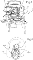
- the second optical body 8 (see also Figures 3 , 5 and 7 ) has an arm 10 for supporting the first prismatic lens 9 articulated to a movement device 11 connected to the frame 3 and configured to rotate the first prismatic lens 9, between several working positions including at least one position of the first prismatic lens 9 close but not coaxial with the trajectory T4 or optical axis of illumination of the light beam, and more positions spaced away from the trajectory T4 or optical axis of illumination of the second prismatic lens 9 in such a way as to create first optical effects which are not in focus; ( figure 3 , 5 and 7 ).
- the projector 1 also comprises a third optical body 12 comprising a second prismatic lens 13, positioned alongside the first prismatic lens 9, having a second number of twists and turns on at least one respective surface for generating a plurality of second optical effects, individually or in combination with the first prismatic lens 9, acting on the light beam.
- a third optical body 12 comprising a second prismatic lens 13, positioned alongside the first prismatic lens 9, having a second number of twists and turns on at least one respective surface for generating a plurality of second optical effects, individually or in combination with the first prismatic lens 9, acting on the light beam.
- the third optical body 12 has an arm 14 for supporting the second prismatic lens 13 articulated to a movement device 15 connected to the frame 3 and configured to rotate the second prismatic lens 13 between several operating positions including at least a position of the second prismatic lens 13 close to but not coaxial with the trajectory T4 or optical axis of illumination of the light beam, and more positions away from the trajectory T4 or optical axis of illumination of the second prismatic lens 9 in such a way as to create second optical effects which are not in focus.
- the projector 1 comprises a control unit 20 in communication with the second 8 and the third 12 optical body and configured for controlling the corresponding devices 11, 15 in such a way as to generate, as required, a plurality of combined optical effects at the outlet maintaining the first 9 or the second lens 13 or in combination of both the lenses in a position again not coaxial, that is to say, not in focus, with the trajectory T4 or optical axis of illumination (see Figures 3 , 5 and from 7 to 9).
- the first prismatic lens 9 has a first number of twists and turns greater than the second number of twists and turns present on the second prismatic lens 13 (see also Figures 8 to 10 ).
- the first prismatic lens 9 has a first number of twists and turns equal to the second number of twists and turns present on the second prismatic lens 13 (this solution being illustrated in Figures 2 , 4 and 6 ).
- the device 11 for moving the first prismatic lens 9 is configured to rotate the first prismatic lens 9 between several operational positions including at least one position of the first prismatic lens 9 close to but not coaxial with the trajectory T4 or optical axis of illumination of the light beam, and more positions outside the axis wherein the first prismatic lens 9 is partly outside the lighting trajectory T4 or optical axis ( Figure 5 ).
- the device 15 for moving the second prismatic lens 13 is configured to rotate the second prismatic lens 13 between several operating positions including at least one position of the second prismatic lens 13 close to but not coaxial with the trajectory T4 or optical axis of illumination of the light beam, and more positions away from the optical axis wherein the second prismatic lens 9 is partly outside the trajectory T4 or optical axis of illumination ( Figure 10 ).
- the devices 11 and 15 for moving the first 9 and the second 13 prismatic lens are programmed to rotate the corresponding first 9 and second 13 prismatic lens in the intermediate operating positions and modify them with a coordinated oscillation between the two prismatic lenses 9, 13 (for example, as illustrated in Figure 10 ) in such a way as to allow dynamic optical effects.
- the devices 11 and 15 for moving the first 9 and second 13 prismatic lens may cause an oscillation with a continuous pendulum movement or rotate and move the corresponding prismatic lens to a new stable angled position as a function of the type of visual effect programmed.
- the movement devices 11 and 15 are in communication with the control unit 20 (illustrated as a block in Figure 1 ) which controls the devices according to the required command (through a software program, for example) sent by the operator.
- the control unit 20 illustrated as a block in Figure 1
- the required command through a software program, for example
- the unit 20 is connected to and also controls the first optical body or zoom 7.
- the device 11 for moving the first prismatic lens 9 comprises a kinematic element 16 configured for the rotation of the first prismatic lens 9 about its own central axis.
- the device 15 for moving the second prismatic lens 13 comprises a kinematic element 17 configured for the rotation of the second prismatic lens 13 about its own central axis.
- Each movement device 11 and 15 comprises a motor-driven axis 11X and 15X on which is articulated the corresponding arm 10 and 14 supporting the prismatic lenses 9 and 13.
- the kinematic means 16 and 17 of rotation of the two prismatic lenses 9 and 13 comprise a cascade of three gear wheels (of which one motor-driven 21 and keyed to the motor-driven axes) and configured to maintain the rotation of the lenses irrespective of the angular position adopted by the lenses.
- the first optical body 7 or zoom for varying the focal length of the light beam is connected to a motor-driven carriage 18 for moving the first optical body 7 along the frame 3.
- the carriage 18 is coupled to a guide 19, extending along the frame 3, in such a way as to allow a plurality of positions of the first optical body 7 along the frame 3 between at least a first position wherein the first optical body 3 is interposed between the light source 4 and the first 9 and second 13 prismatic lens ( Figures 1 , 4 and 6 ) or between the outlet lens 6 and the first 9 and second 13 prismatic lens.
- the first prismatic lens 9 can have a series of twists and turns which are able to duplicate the light beam in twenty-four images arranged in groups on concentric circular rings (see Figures 2 to 10 ).
- the second lens 13 has a series of twists and turns which are able to duplicate the light beam in six images arranged in line on one side or the other (see figures 8 to 10 ).
- the pair of lenses and the above-mentioned features the specific features of the projector increase considerably compared with respect to the traditional solutions thanks to the out of focus positions, that is to say, not in axial alignment with the optical axis.
- the overall size of the projector is reduced also with reference to the quantity of visual effects which can be reproduced with these features.
Landscapes
- Engineering & Computer Science (AREA)
- General Engineering & Computer Science (AREA)
- Physics & Mathematics (AREA)
- General Physics & Mathematics (AREA)
- Optics & Photonics (AREA)
- Non-Portable Lighting Devices Or Systems Thereof (AREA)
- Projection Apparatus (AREA)
- Eye Examination Apparatus (AREA)
Applications Claiming Priority (1)
| Application Number | Priority Date | Filing Date | Title |
|---|---|---|---|
| IT102018000005776A IT201800005776A1 (it) | 2018-05-28 | 2018-05-28 | Proiettore di un fascio luminoso. |
Publications (1)
| Publication Number | Publication Date |
|---|---|
| EP3575868A1 true EP3575868A1 (de) | 2019-12-04 |
Family
ID=63244877
Family Applications (1)
| Application Number | Title | Priority Date | Filing Date |
|---|---|---|---|
| EP19175170.0A Withdrawn EP3575868A1 (de) | 2018-05-28 | 2019-05-17 | Projektor eines lichtstrahls |
Country Status (4)
| Country | Link |
|---|---|
| US (1) | US10955115B2 (de) |
| EP (1) | EP3575868A1 (de) |
| CN (1) | CN110543068A (de) |
| IT (1) | IT201800005776A1 (de) |
Cited By (1)
| Publication number | Priority date | Publication date | Assignee | Title |
|---|---|---|---|---|
| IT202300021735A1 (it) * | 2023-10-18 | 2025-04-18 | Music & Lights S R L | Proiettore di fasci luminosi |
Families Citing this family (5)
| Publication number | Priority date | Publication date | Assignee | Title |
|---|---|---|---|---|
| US10907798B2 (en) * | 2019-06-13 | 2021-02-02 | The Kirlin Company | System and method for adjusting beam size while maintaining beam brightness |
| CN114729738B (zh) * | 2019-11-21 | 2025-01-17 | 三菱电机株式会社 | 照明装置 |
| IT202100000377A1 (it) * | 2021-01-11 | 2022-07-11 | Osram Gmbh | Dispositivo di illuminazione e corrispondente procedimento di azionamento |
| CN116677931A (zh) * | 2023-06-14 | 2023-09-01 | 深圳市联域光电股份有限公司 | 一种led灯 |
| FR3160226B1 (fr) * | 2024-03-18 | 2026-04-17 | Ayrton | Projecteur comprenant au moins un premier et un deuxième dispositif à prisme |
Citations (5)
| Publication number | Priority date | Publication date | Assignee | Title |
|---|---|---|---|---|
| EP1167868A2 (de) * | 2000-06-27 | 2002-01-02 | COEMAR S.p.A. | Scheinwerfer, insbesondere zum Projizieren von Lichtbündeln verschiedener Abmessungen und Farben |
| US20120121244A1 (en) * | 2010-11-15 | 2012-05-17 | Congruent Concepts, LLC | Variable focus illuminator |
| WO2012138770A2 (en) * | 2011-04-04 | 2012-10-11 | Robe Lighting Inc | A dual graphic wheel for an automated luminaire |
| WO2015022644A1 (en) * | 2013-08-12 | 2015-02-19 | Clay Paky S.P.A. | Stage light fixture, in particular multisource stage light fixture |
| EP3056804A1 (de) * | 2015-02-16 | 2016-08-17 | D.T.S. Illuminazione S.r.l. | Projektor von lichtstrahlen |
Family Cites Families (3)
| Publication number | Priority date | Publication date | Assignee | Title |
|---|---|---|---|---|
| US4037097A (en) * | 1975-04-04 | 1977-07-19 | Stillman Allen M | Color changer for spotlights |
| US6971770B2 (en) * | 2001-09-06 | 2005-12-06 | Martin Professional A/S | Lighting apparatus |
| US10724709B2 (en) * | 2014-10-01 | 2020-07-28 | Robe Lighting S.R.O. | Coordinated effects system for an automated luminaire |
-
2018
- 2018-05-28 IT IT102018000005776A patent/IT201800005776A1/it unknown
-
2019
- 2019-05-17 EP EP19175170.0A patent/EP3575868A1/de not_active Withdrawn
- 2019-05-20 US US16/417,060 patent/US10955115B2/en not_active Expired - Fee Related
- 2019-05-27 CN CN201910445177.5A patent/CN110543068A/zh active Pending
Patent Citations (5)
| Publication number | Priority date | Publication date | Assignee | Title |
|---|---|---|---|---|
| EP1167868A2 (de) * | 2000-06-27 | 2002-01-02 | COEMAR S.p.A. | Scheinwerfer, insbesondere zum Projizieren von Lichtbündeln verschiedener Abmessungen und Farben |
| US20120121244A1 (en) * | 2010-11-15 | 2012-05-17 | Congruent Concepts, LLC | Variable focus illuminator |
| WO2012138770A2 (en) * | 2011-04-04 | 2012-10-11 | Robe Lighting Inc | A dual graphic wheel for an automated luminaire |
| WO2015022644A1 (en) * | 2013-08-12 | 2015-02-19 | Clay Paky S.P.A. | Stage light fixture, in particular multisource stage light fixture |
| EP3056804A1 (de) * | 2015-02-16 | 2016-08-17 | D.T.S. Illuminazione S.r.l. | Projektor von lichtstrahlen |
Cited By (2)
| Publication number | Priority date | Publication date | Assignee | Title |
|---|---|---|---|---|
| IT202300021735A1 (it) * | 2023-10-18 | 2025-04-18 | Music & Lights S R L | Proiettore di fasci luminosi |
| EP4542110A1 (de) * | 2023-10-18 | 2025-04-23 | Music & Lights S.r.l. | Projektor für lichtstrahlen |
Also Published As
| Publication number | Publication date |
|---|---|
| CN110543068A (zh) | 2019-12-06 |
| IT201800005776A1 (it) | 2019-11-28 |
| US10955115B2 (en) | 2021-03-23 |
| US20190360665A1 (en) | 2019-11-28 |
Similar Documents
| Publication | Publication Date | Title |
|---|---|---|
| US10955115B2 (en) | Projector of a light beam | |
| EP3056804B1 (de) | Projektor von lichtstrahlen | |
| US4868718A (en) | Forward illumination lighting system for vehicles | |
| EP2443386B1 (de) | Led-lichtemissionsgruppe | |
| EP3112746B1 (de) | Prismeneffektsystem mit mehrregionen-farbfilter und facettenreichem prisma | |
| JPH0584602B2 (de) | ||
| EP3112745B1 (de) | Prismenwirkungssystem für einen beleuchtungskörper mit umgekehrten mehrfachfacettenprismen | |
| HK95690A (en) | Light source with colour filter | |
| WO2015138483A2 (en) | Optical system for an led luminaire | |
| WO2015077384A1 (en) | Luminaire with articulated leds | |
| US20190120447A1 (en) | Light fixture, preferably for stage | |
| US8408755B2 (en) | Stage lighting fixture and method of operating a stage lighting fixture | |
| US6502961B1 (en) | Conical lens array to control projected light beam color, divergence, and shape | |
| WO2011032057A1 (en) | Improved optics for an automated luminaire | |
| US20130058094A1 (en) | Versatile beam and wash optical system for an automated luminaire | |
| US5915823A (en) | Central source light distribution system and components for maintaining beam continuity to adjustably positionable remote illumination directors | |
| CN104395669A (zh) | 用于自动照明器的改进的漫射系统 | |
| JP2007531229A (ja) | 可変ビームを有する投光照明 | |
| EP3135992B1 (de) | Beleuchtungsvorrichtung und szenographischer projektor mit mehreren solcher beleuchtungsvorrichtungen | |
| EP1844262B1 (de) | Optisches system für ein washlight | |
| US20080309888A1 (en) | Stage projector structure | |
| US6508579B1 (en) | Lighting apparatus for illuminating well-defined limited areas | |
| US6161945A (en) | Projector device for a multi-color light beam | |
| JP2018206668A (ja) | 照明装置 | |
| EP3816504B1 (de) | System und verfahren zur erzeugung einer mischlichtverteilung aus led-leuchten |
Legal Events
| Date | Code | Title | Description |
|---|---|---|---|
| PUAI | Public reference made under article 153(3) epc to a published international application that has entered the european phase |
Free format text: ORIGINAL CODE: 0009012 |
|
| AK | Designated contracting states |
Kind code of ref document: A1 Designated state(s): AL AT BE BG CH CY CZ DE DK EE ES FI FR GB GR HR HU IE IS IT LI LT LU LV MC MK MT NL NO PL PT RO RS SE SI SK SM TR |
|
| AX | Request for extension of the european patent |
Extension state: BA ME |
|
| 17P | Request for examination filed |
Effective date: 20200526 |
|
| RBV | Designated contracting states (corrected) |
Designated state(s): AL AT BE BG CH CY CZ DE DK EE ES FI FR GB GR HR HU IE IS IT LI LT LU LV MC MK MT NL NO PL PT RO RS SE SI SK SM TR |
|
| GRAP | Despatch of communication of intention to grant a patent |
Free format text: ORIGINAL CODE: EPIDOSNIGR1 |
|
| STAA | Information on the status of an ep patent application or granted ep patent |
Free format text: STATUS: GRANT OF PATENT IS INTENDED |
|
| RIC1 | Information provided on ipc code assigned before grant |
Ipc: G03B 21/14 20060101AFI20200615BHEP |
|
| INTG | Intention to grant announced |
Effective date: 20200710 |
|
| RIN1 | Information on inventor provided before grant (corrected) |
Inventor name: LATTEO, ELISEO |
|
| 18D | Application deemed to be withdrawn |
Effective date: 20201121 |