EP3575818A1 - Radar device and method for preventing radio wave interference - Google Patents
Radar device and method for preventing radio wave interference Download PDFInfo
- Publication number
- EP3575818A1 EP3575818A1 EP17894640.6A EP17894640A EP3575818A1 EP 3575818 A1 EP3575818 A1 EP 3575818A1 EP 17894640 A EP17894640 A EP 17894640A EP 3575818 A1 EP3575818 A1 EP 3575818A1
- Authority
- EP
- European Patent Office
- Prior art keywords
- radio interference
- pulse pattern
- radio
- radar apparatus
- antenna
- Prior art date
- Legal status (The legal status is an assumption and is not a legal conclusion. Google has not performed a legal analysis and makes no representation as to the accuracy of the status listed.)
- Withdrawn
Links
Images


Classifications
-
- G—PHYSICS
- G01—MEASURING; TESTING
- G01S—RADIO DIRECTION-FINDING; RADIO NAVIGATION; DETERMINING DISTANCE OR VELOCITY BY USE OF RADIO WAVES; LOCATING OR PRESENCE-DETECTING BY USE OF THE REFLECTION OR RERADIATION OF RADIO WAVES; ANALOGOUS ARRANGEMENTS USING OTHER WAVES
- G01S13/00—Systems using the reflection or reradiation of radio waves, e.g. radar systems; Analogous systems using reflection or reradiation of waves whose nature or wavelength is irrelevant or unspecified
- G01S13/02—Systems using reflection of radio waves, e.g. primary radar systems; Analogous systems
- G01S13/06—Systems determining position data of a target
- G01S13/08—Systems for measuring distance only
- G01S13/10—Systems for measuring distance only using transmission of interrupted, pulse modulated waves
- G01S13/22—Systems for measuring distance only using transmission of interrupted, pulse modulated waves using irregular pulse repetition frequency
-
- G—PHYSICS
- G01—MEASURING; TESTING
- G01S—RADIO DIRECTION-FINDING; RADIO NAVIGATION; DETERMINING DISTANCE OR VELOCITY BY USE OF RADIO WAVES; LOCATING OR PRESENCE-DETECTING BY USE OF THE REFLECTION OR RERADIATION OF RADIO WAVES; ANALOGOUS ARRANGEMENTS USING OTHER WAVES
- G01S13/00—Systems using the reflection or reradiation of radio waves, e.g. radar systems; Analogous systems using reflection or reradiation of waves whose nature or wavelength is irrelevant or unspecified
- G01S13/02—Systems using reflection of radio waves, e.g. primary radar systems; Analogous systems
- G01S13/06—Systems determining position data of a target
- G01S13/08—Systems for measuring distance only
- G01S13/10—Systems for measuring distance only using transmission of interrupted, pulse modulated waves
- G01S13/24—Systems for measuring distance only using transmission of interrupted, pulse modulated waves using frequency agility of carrier wave
-
- G—PHYSICS
- G01—MEASURING; TESTING
- G01S—RADIO DIRECTION-FINDING; RADIO NAVIGATION; DETERMINING DISTANCE OR VELOCITY BY USE OF RADIO WAVES; LOCATING OR PRESENCE-DETECTING BY USE OF THE REFLECTION OR RERADIATION OF RADIO WAVES; ANALOGOUS ARRANGEMENTS USING OTHER WAVES
- G01S7/00—Details of systems according to groups G01S13/00, G01S15/00, G01S17/00
- G01S7/02—Details of systems according to groups G01S13/00, G01S15/00, G01S17/00 of systems according to group G01S13/00
- G01S7/023—Interference mitigation, e.g. reducing or avoiding non-intentional interference with other HF-transmitters, base station transmitters for mobile communication or other radar systems, e.g. using electro-magnetic interference [EMI] reduction techniques
-
- G—PHYSICS
- G01—MEASURING; TESTING
- G01S—RADIO DIRECTION-FINDING; RADIO NAVIGATION; DETERMINING DISTANCE OR VELOCITY BY USE OF RADIO WAVES; LOCATING OR PRESENCE-DETECTING BY USE OF THE REFLECTION OR RERADIATION OF RADIO WAVES; ANALOGOUS ARRANGEMENTS USING OTHER WAVES
- G01S7/00—Details of systems according to groups G01S13/00, G01S15/00, G01S17/00
- G01S7/02—Details of systems according to groups G01S13/00, G01S15/00, G01S17/00 of systems according to group G01S13/00
- G01S7/36—Means for anti-jamming, e.g. ECCM, i.e. electronic counter-counter measures
-
- H—ELECTRICITY
- H04—ELECTRIC COMMUNICATION TECHNIQUE
- H04K—SECRET COMMUNICATION; JAMMING OF COMMUNICATION
- H04K3/00—Jamming of communication; Counter-measures
- H04K3/20—Countermeasures against jamming
- H04K3/22—Countermeasures against jamming including jamming detection and monitoring
- H04K3/224—Countermeasures against jamming including jamming detection and monitoring with countermeasures at transmission and/or reception of the jammed signal, e.g. stopping operation of transmitter or receiver, nulling or enhancing transmitted power in direction of or at frequency of jammer
-
- H—ELECTRICITY
- H04—ELECTRIC COMMUNICATION TECHNIQUE
- H04K—SECRET COMMUNICATION; JAMMING OF COMMUNICATION
- H04K3/00—Jamming of communication; Counter-measures
- H04K3/20—Countermeasures against jamming
- H04K3/22—Countermeasures against jamming including jamming detection and monitoring
- H04K3/224—Countermeasures against jamming including jamming detection and monitoring with countermeasures at transmission and/or reception of the jammed signal, e.g. stopping operation of transmitter or receiver, nulling or enhancing transmitted power in direction of or at frequency of jammer
- H04K3/226—Selection of non-jammed channel for communication
-
- G—PHYSICS
- G01—MEASURING; TESTING
- G01S—RADIO DIRECTION-FINDING; RADIO NAVIGATION; DETERMINING DISTANCE OR VELOCITY BY USE OF RADIO WAVES; LOCATING OR PRESENCE-DETECTING BY USE OF THE REFLECTION OR RERADIATION OF RADIO WAVES; ANALOGOUS ARRANGEMENTS USING OTHER WAVES
- G01S13/00—Systems using the reflection or reradiation of radio waves, e.g. radar systems; Analogous systems using reflection or reradiation of waves whose nature or wavelength is irrelevant or unspecified
- G01S13/88—Radar or analogous systems specially adapted for specific applications
- G01S13/95—Radar or analogous systems specially adapted for specific applications for meteorological use
-
- H—ELECTRICITY
- H04—ELECTRIC COMMUNICATION TECHNIQUE
- H04K—SECRET COMMUNICATION; JAMMING OF COMMUNICATION
- H04K2203/00—Jamming of communication; Countermeasures
- H04K2203/30—Jamming or countermeasure characterized by the infrastructure components
- H04K2203/32—Jamming or countermeasure characterized by the infrastructure components including a particular configuration of antennas
-
- H—ELECTRICITY
- H04—ELECTRIC COMMUNICATION TECHNIQUE
- H04K—SECRET COMMUNICATION; JAMMING OF COMMUNICATION
- H04K2203/00—Jamming of communication; Countermeasures
- H04K2203/30—Jamming or countermeasure characterized by the infrastructure components
- H04K2203/36—Jamming or countermeasure characterized by the infrastructure components including means for exchanging jamming data between transmitter and receiver, e.g. in forward or backward direction
-
- Y—GENERAL TAGGING OF NEW TECHNOLOGICAL DEVELOPMENTS; GENERAL TAGGING OF CROSS-SECTIONAL TECHNOLOGIES SPANNING OVER SEVERAL SECTIONS OF THE IPC; TECHNICAL SUBJECTS COVERED BY FORMER USPC CROSS-REFERENCE ART COLLECTIONS [XRACs] AND DIGESTS
- Y02—TECHNOLOGIES OR APPLICATIONS FOR MITIGATION OR ADAPTATION AGAINST CLIMATE CHANGE
- Y02A—TECHNOLOGIES FOR ADAPTATION TO CLIMATE CHANGE
- Y02A90/00—Technologies having an indirect contribution to adaptation to climate change
- Y02A90/10—Information and communication technologies [ICT] supporting adaptation to climate change, e.g. for weather forecasting or climate simulation
Definitions
- An embodiment of the present invention relates to a radar apparatus and a method for avoiding a radio interference.
- a wireless communication device such as a wireless LAN promotes a higher frequency of a use frequency for a purpose of large volume communication.
- use frequency bands of the wireless communication device and a radar apparatus such as a weather radar overlap, and therefore a radio interference is highly likely to occur.
- an access point of the wireless LAN includes a mounted radio interference avoiding function which is generally called DFS (Dynamic Frequency Selection).
- a DFS function is mounted on an access point of a wireless LAN.
- This DFS function determines whether or not a signal received by the access point includes a pulse pattern of a radar apparatus defined in advance.
- the pulse pattern is defined based on parameters such as a pulse width, a pulse repetition frequency (pulse repetition interval) and the number of pulses.
- the DFS function avoids an interference with a transmission pulse signal of the radar apparatus by changing a channel to a channel of another frequency.
- the DFS function interrupts use of the channel of this frequency only for a certain time (e.g., 30 minutes). After the certain time passes, this channel is used again and a radio interference is likely to occur.
- the DFS function of the access point of the wireless LAN is not validated due to some cause, and is likely to cause the radio interference eventually.
- a radar apparatus employs a configuration including a radio interference determining unit, a selecting unit and a transmitting unit.
- the radio interference determining unit is configured to determine whether or not there is a radio interference, based on a radio signal received via an antenna.
- the selecting unit is configured to, when the radio interference determining unit determines that there is the radio interference, select a pulse pattern defined in advance based on an avoiding function of a wireless communication device having the avoiding function of the radio interference.
- the transmitting unit is configured to transmit from the antenna a radio signal matching the pulse pattern selected by the selecting unit.
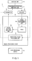
- FIG. 1 is a block diagram illustrating a configuration of a radar apparatus according to the present embodiment.
- a radar apparatus 1 includes an antenna unit 10, a transmission/determination switching unit 11, a transmitter 12, a receiver 13, a signal processing device 14 and a data processing device 19.
- the antenna unit 10 is, for example, a parabolic antenna device or an array antenna device formed by a plurality of antenna elements.
- the transmission/determination switching unit 11 switches transmission/determination processing of a radar signal, and transfers a transmission pulse from the transmitter 12 to the antenna unit 10 or transfers a radio signal received from the antenna unit 10 to the receiver 13.
- the transmitter 12 generates the transmission pulse (radar signal) matching a pulse pattern outputted from the signal processing device 14, and outputs the transmission pulse to the antenna unit 10.
- the signal processing device 14 according to the present embodiment outputs a pulse pattern (referred to as an operational pulse pattern for ease of description in some cases) which is necessary for a normal operation (detection, observation and measurement) for a normal radar operation to the transmitter 12.
- the signal processing device 14 outputs a pulse pattern related to a radio interference avoiding function according to the present embodiment to the transmitter 12, as described below.
- the receiver 13 digitally processes the radio signal received by the antenna unit 10, and outputs the processed received signal to the signal processing device 14.
- the received signal includes not only an echo signal of the transmitted radar signal, but also a radio signal transmitted from a wireless communication device such as a wireless LAN as described below.
- the signal processing device 14 includes an operational pulse processing unit 15 which outputs the operational pulse pattern to the transmitter 12 during transmission, and processes the received signal outputted from the receiver 13 during determination. That is, the operational pulse processing unit 15 processes transmission/received signals which are necessary for the normal operation (detection, observation and measurement) for a normal radar operation.
- the data processing device 19 executes data processing which is necessary for the normal operation (detection, observation and measurement) for the radar operation based on transmission/determination processing of the operational pulse processing unit 15.
- the present embodiment omits description of a configuration and an operation of the operational pulse processing unit 15, and the transmission/determination processing related to the normal operation (detection, observation and measurement) for the radar operation. Furthermore, to distinguish from the transmission/determination processing related to the normal operation for operating the radar, transmission/determination processing will be expressed as the transmission/determination processing on the radio interference avoiding function in some cases.
- the signal processing device 14 includes a pulse pattern selecting unit 16, a table 17 and a radio interference determining unit 18 as components for realizing the radio interference avoiding function.
- the pulse pattern selecting unit 16 outputs the pulse pattern selected from a plurality of pulse patterns defined in advance to the transmitter 12. These pulse patterns are defined separately from the operational pulse pattern used for the normal operation (detection, observation and measurement) for the radar operation.
- a plurality of pulse patterns is selected from a pulse pattern table 170 included in the table 17.
- the table 17 includes the pulse pattern table 170 and a radio interference countermeasure table 171.
- FIG. 2 is a view illustrating one example of the pulse pattern table 170.
- the pulse pattern table 170 includes, for example, pulse patterns of a plurality of types (which is two types of T1 and T2 for ease of description) defined for the weather radar based on, for example, a law and standards of a country.
- the types T1 and T2 are respectively pulse patterns defined by parameters such as pulse widths (PW1 and PW2), pulse repetition frequencies (PRF1 and PRF2), the numbers of pulses (PN1 and PN2) and frequency sweep widths (FW1 and FW2).
- the pulse pattern table 170 can be updated by adding new types of pulse patterns by an online or offline method or changing existing pulse patterns according to, for example, a change in the law or the standards of the country.
- FIG. 3 is a view illustrating one example of the radio interference countermeasure table 171.
- the countermeasure table 171 is a table which records the types T1 and T2 indicating whether or not there is a radio interference, and valid pulse patterns per elevation angle and azimuth angle of an antenna during determination processing on the radio interference avoiding function as described below.
- the radio interference determining unit 18 determines whether or not there is a radio interference with the wireless communication device as described below during determination of the transmission/determination processing on the radio interference avoiding function.
- the present embodiment assumes, for example, the access point of the wireless LAN including a DFS function as the wireless communication device.
- the radio interference determining unit 18 determines that there is the radio interference with the wireless communication device which transmitted the radio signal, when a fluctuation in a distance direction (time direction) of a receiving level of the radio signal received by the antenna is within a predetermined range (the fluctuation is a fixed fluctuation which is impossible in a natural phenomenon) based on the radio signal received by the antenna during reception processing on the radio interference avoiding function.
- the radio interference determining unit 18 determines that there is the radio interference with the wireless communication device which transmitted the radio signal, when the fluctuation of the receiving level at the same distance of a plurality of transmission pulses exceeds the predetermined range (the fluctuation shows a binary change which is impossible in the natural phenomenon).
- FIG. 4 is a flowchart for explaining the operation of the radar apparatus 1.
- the present embodiment omits description of the normal operation (detection, observation and measurement) of the operational pulse processing unit 15 for the radar operation.
- the signal processing device 14 executes transmission/determination processing on the radio interference avoiding function separately from the transmission/determination processing during the normal operation for the radar operation.
- the signal processing device 14 executes determination processing on the radio interference avoiding function (step S1).
- the receiver 13 in the radar apparatus 1 outputs to the signal processing device 14 the received signal obtained by digitally processing the radio signal received by the antenna unit 10.
- the received signal includes a radio signal, too, transmitted from the wireless communication device such as the wireless LAN.
- the radio interference determining unit 18 in the signal processing device 14 executes determination processing of determining whether or not there is a radio interference with the wireless communication device such as the wireless LAN during the determination processing on the radio interference avoiding function (step S2).
- the determination processing can be performed by focusing on a difference between a meteorological echo and a wireless communication signal.
- the radio interference determining unit 18 determines that there is the radio interference.
- the radio interference determining unit 18 sets whether or not there is the radio interference per elevation angle and azimuth angle to the radio interference countermeasure table 171 based on a radio interference decision result.
- the radio interference determining unit 18 determines and sets that there is the radio interference to the countermeasure table 171
- the signal processing device 14 transitions to transmission processing on the radio interference avoiding function (YES in step S3).
- the radio interference determining unit 18 may determine whether or not there is the radio interference for all azimuth angles per elevation angle of the antenna, the signal processing device 14 may transition to transmission processing.
- the signal processing device 14 may transition to the transmission processing.
- the pulse pattern selecting unit 16 selects, for example, the pulse pattern of the type T1 from the pulse pattern table 170 (step S4).
- the pulse pattern selecting unit 16 may select pulse patterns in order from the pulse pattern table 170 or may select a pulse pattern in order from, for example, pulse patterns of a type similar to the parameters of the operational pulse pattern.
- the pulse pattern selecting unit 16 selects, for example, the pulse pattern of the type T1, and outputs the pulse pattern to the transmitter 12.
- the transmitter 12 in the radar apparatus 1 generates a transmission pulse matching the pulse pattern of the type T1, and outputs the transmission pulse to the antenna unit 10.
- the radar apparatus 1 executes transmission processing of transmitting a radio signal matching the transmission pulse from the antenna unit 10 (step S5).
- the signal processing device 14 executes determination processing on the radio interference avoiding function (step S6).
- the radio interference determining unit 18 executes decision processing of determining whether or not there is a radio interference similar to the above (step S7).
- the radio interference determining unit 18 sets information (T1 in this case) indicating that the transmitted pulse pattern of the type T1 is a valid pulse pattern to an item "valid" of the countermeasure table 171 as illustrated in FIG. 3 (NO in step S8, S9). That is, as illustrated in FIG. 3 , information indicating the valid pulse pattern is set per elevation angle and azimuth angle of the antenna during determination to the countermeasure table 171.
- the valid pulse pattern is a pulse pattern which is detected by the DFS function of the access point of the wireless LAN which is the wireless communication device and is a target of radio interference avoiding processing of the DFS function.
- the access point of the wireless LAN detects a radio signal matching the pulse pattern of the type T1 by the DFS function, stops transmission of the radio signal which was determined to cause the radio interference, and changes the frequency of the radio signal by switching a channel.
- the access point of the wireless LAN can eventually recognize the presence of the radar apparatus 1 and avoid the radio interference.
- the signal processing device 14 executes the transmission processing on the radio interference avoiding function matching the valid pulse pattern (type T1 in this case) set to the countermeasure table 171.
- the access point of the wireless LAN is more highly likely to be able to reliably execute radio interference avoid processing by the DFS function, and reliably avoid the radio interference.
- the radio interference determining unit 18 determines the radio interference as "Yes” (YES in step S8), the signal processing device 14 repeats processing from step S4. That is, the pulse pattern selecting unit 16 selects, for example, the pulse pattern of the type T2 from the pulse pattern table 170, and outputs the pulse pattern to the transmitter 12. Similarly, when determining that there is no radio interference, the radio interference determining unit 18 sets information (T2 in this case) indicating that the transmitted pulse pattern of the type T2 is a valid pulse pattern to the item "valid" of the countermeasure table 171 (NO in step S8, S9).
- the radio interference determining unit 18 determines whether or not there is a radio interference during the determination processing on the radio interference avoiding function.
- this decision result shows that there is the radio interference
- the transmission processing on the radio interference avoiding function of transmitting a pulse pattern defined in advance is executed. Consequently, when, for example, the access point of the wireless LAN having the DFS function can detect the pulse pattern by the DFS function, the access point can eventually recognize the presence of the radar apparatus 1 and avoid the radio interference.
- the radio interference avoiding function determines the pulse pattern transmitted during the transmission processing on the radio interference avoiding function as valid
- the pulse pattern can be set as the valid pulse pattern. Consequently, the radar apparatus 1 according to the present embodiment can eventually reliably realize the radio interference avoiding function by transmitting this valid pulse pattern. In this case, the radar apparatus 1 can effectively exhibit the radio interference avoiding function by transmitting the valid pulse pattern per elevation angle and azimuth angle on a regular basis as illustrated in FIG. 3 .
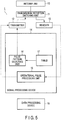
- FIG. 5 is a block diagram illustrating a configuration of the radar apparatus 1 according to the modification of the present embodiment.
- the signal processing device 14 in the radar apparatus 1 according to this modification employs a configuration which includes the pulse pattern selecting unit 16 and the table 17 as components for realizing the radio interference avoiding function and which omits the radio interference determining unit 18 according to the present embodiment.
- the other components are the same as the components of the radar apparatus 1 according to the present embodiment illustrated in FIG. 1 , and therefore description thereof will be omitted.
- the pulse pattern table 170 included in the table 17 may be used, and the countermeasure table 171 may be omitted.
- this modification omits description of the configuration and the operation of the operational pulse processing unit 15, and the transmission/determination processing related to the normal operation (detection, observation and measurement) for the radar operation.
- the radar apparatus 1 By executing transmission processing on the radio interference avoiding function, the radar apparatus 1 according to this modification can eventually increase a probability that it is possible to avoid a radio interference with the wireless communication device such as the access point of the wireless LAN. More specifically, according to the transmission processing on the radio interference avoiding function, the pulse pattern selecting unit 16 selects, for example, the pulse pattern of the type T1 from the pulse pattern table 170, and outputs the pulse pattern to the transmitter 12. The transmitter 12 generates a transmission pulse matching the pulse pattern of the type T1, and outputs the transmission pulse to the antenna unit 10. That is, the radar apparatus 1 executes transmission processing of transmitting a radio signal matching the transmission pulse from the antenna unit 10.
- the access point of the wireless LAN which is the wireless communication device and has the DFS function can receive a radio signal from the radar apparatus 1 by the DFS function, and detect the pulse pattern of the type T1.
- the access point of the wireless LAN recognizes the presence of the radar apparatus 1 and executes processing of avoiding the radio interference.
- the pulse pattern selecting unit 16 in the radar apparatus 1 may alternately select, for example, each pulse pattern of the types T1 and T2 per predetermined period.
- the access point of the wireless LAN having the DFS function can detect the pulse pattern by the DFS function, and execute processing of avoiding the radio interference. Consequently, the access point having the DFS function recognizes the presence of the radar apparatus 1 according to the present embodiment, and eventually increases a probability that the radio interference avoiding function is effectively executed.
- the present embodiment and the modification have described, for example, the access point of the wireless LAN as the wireless communication device, yet are not limited to this and are applicable to various wireless communication devices, too, which are likely to cause a radio interference with the radar apparatus.
- the present embodiment and the modification have described the DFS function as the radio interference avoiding function, yet are not limited to this. Another system may be employed as long as this system has a function of detecting a radio signal of the radar apparatus and stopping use of this frequency.
Landscapes
- Engineering & Computer Science (AREA)
- Radar, Positioning & Navigation (AREA)
- Remote Sensing (AREA)
- Computer Networks & Wireless Communication (AREA)
- Physics & Mathematics (AREA)
- General Physics & Mathematics (AREA)
- Signal Processing (AREA)
- Electromagnetism (AREA)
- Radar Systems Or Details Thereof (AREA)
- Mobile Radio Communication Systems (AREA)
Abstract
Description
- An embodiment of the present invention relates to a radar apparatus and a method for avoiding a radio interference.
- In recent years, a wireless communication device such as a wireless LAN promotes a higher frequency of a use frequency for a purpose of large volume communication. Hence, use frequency bands of the wireless communication device and a radar apparatus such as a weather radar overlap, and therefore a radio interference is highly likely to occur.
- Conventionally, in a case of, for example, the wireless LAN which uses a frequency band of 5 GHz, this frequency band is used by the radar apparatus such as the weather radar is used, and therefore the radio interference is likely to occur. As a countermeasure for avoiding this radio interference, an access point of the wireless LAN includes a mounted radio interference avoiding function which is generally called DFS (Dynamic Frequency Selection).
-
- Patent Literature 1: Jpn. Pat. Appln. KOKAI Publication No.
2012-120033 - Patent Literature 2: Jpn. Pat. Appln. KOKAI Publication No.
2007-274659 - Patent Literature 3: Jpn. Pat. Appln. KOKAI Publication No.
2001-285301 - As a measure for avoiding a radio interference, for example, a DFS function is mounted on an access point of a wireless LAN. This DFS function determines whether or not a signal received by the access point includes a pulse pattern of a radar apparatus defined in advance. The pulse pattern is defined based on parameters such as a pulse width, a pulse repetition frequency (pulse repetition interval) and the number of pulses. When determining (detecting) that the pulse pattern is included, the DFS function avoids an interference with a transmission pulse signal of the radar apparatus by changing a channel to a channel of another frequency. In this regard, when detecting the pulse pattern of the radar apparatus, the DFS function interrupts use of the channel of this frequency only for a certain time (e.g., 30 minutes). After the certain time passes, this channel is used again and a radio interference is likely to occur. Furthermore, the DFS function of the access point of the wireless LAN is not validated due to some cause, and is likely to cause the radio interference eventually.
- It is therefore a task to realize a radar apparatus which can avoid a radio interference with a wireless communication device which has a radio interference avoiding function.
- A radar apparatus according to the present embodiment employs a configuration including a radio interference determining unit, a selecting unit and a transmitting unit. The radio interference determining unit is configured to determine whether or not there is a radio interference, based on a radio signal received via an antenna. The selecting unit is configured to, when the radio interference determining unit determines that there is the radio interference, select a pulse pattern defined in advance based on an avoiding function of a wireless communication device having the avoiding function of the radio interference. The transmitting unit is configured to transmit from the antenna a radio signal matching the pulse pattern selected by the selecting unit.
-
-
FIG. 1 is a block diagram for explaining a configuration of a radar apparatus according to an embodiment. -
FIG. 2 is a view illustrating one example of a pulse pattern table according to the embodiment. -
FIG. 3 is a view illustrating one example of a radio interference countermeasure table according to the embodiment. -
FIG. 4 is a flowchart for explaining an operation of the radar apparatus according to the embodiment. -
FIG. 5 is a block diagram for explaining a modification of the embodiment. - The embodiment will be described below with reference to the drawings.
-
FIG. 1 is a block diagram illustrating a configuration of a radar apparatus according to the present embodiment. As illustrated inFIG. 1 , aradar apparatus 1 includes anantenna unit 10, a transmission/determination switching unit 11, atransmitter 12, areceiver 13, asignal processing device 14 and adata processing device 19. Theantenna unit 10 is, for example, a parabolic antenna device or an array antenna device formed by a plurality of antenna elements. The transmission/determination switching unit 11 switches transmission/determination processing of a radar signal, and transfers a transmission pulse from thetransmitter 12 to theantenna unit 10 or transfers a radio signal received from theantenna unit 10 to thereceiver 13. - The
transmitter 12 generates the transmission pulse (radar signal) matching a pulse pattern outputted from thesignal processing device 14, and outputs the transmission pulse to theantenna unit 10. Thesignal processing device 14 according to the present embodiment outputs a pulse pattern (referred to as an operational pulse pattern for ease of description in some cases) which is necessary for a normal operation (detection, observation and measurement) for a normal radar operation to thetransmitter 12. In addition, thesignal processing device 14 outputs a pulse pattern related to a radio interference avoiding function according to the present embodiment to thetransmitter 12, as described below. - The
receiver 13 digitally processes the radio signal received by theantenna unit 10, and outputs the processed received signal to thesignal processing device 14. The received signal includes not only an echo signal of the transmitted radar signal, but also a radio signal transmitted from a wireless communication device such as a wireless LAN as described below. - The
signal processing device 14 includes an operationalpulse processing unit 15 which outputs the operational pulse pattern to thetransmitter 12 during transmission, and processes the received signal outputted from thereceiver 13 during determination. That is, the operationalpulse processing unit 15 processes transmission/received signals which are necessary for the normal operation (detection, observation and measurement) for a normal radar operation. In the present embodiment, thedata processing device 19 executes data processing which is necessary for the normal operation (detection, observation and measurement) for the radar operation based on transmission/determination processing of the operationalpulse processing unit 15. In addition, the present embodiment omits description of a configuration and an operation of the operationalpulse processing unit 15, and the transmission/determination processing related to the normal operation (detection, observation and measurement) for the radar operation. Furthermore, to distinguish from the transmission/determination processing related to the normal operation for operating the radar, transmission/determination processing will be expressed as the transmission/determination processing on the radio interference avoiding function in some cases. - The
signal processing device 14 according to the present embodiment includes a pulsepattern selecting unit 16, a table 17 and a radiointerference determining unit 18 as components for realizing the radio interference avoiding function. The pulsepattern selecting unit 16 outputs the pulse pattern selected from a plurality of pulse patterns defined in advance to thetransmitter 12. These pulse patterns are defined separately from the operational pulse pattern used for the normal operation (detection, observation and measurement) for the radar operation. A plurality of pulse patterns is selected from a pulse pattern table 170 included in the table 17. The table 17 includes the pulse pattern table 170 and a radio interference countermeasure table 171. -
FIG. 2 is a view illustrating one example of the pulse pattern table 170. As illustrated inFIG. 2 , the pulse pattern table 170 includes, for example, pulse patterns of a plurality of types (which is two types of T1 and T2 for ease of description) defined for the weather radar based on, for example, a law and standards of a country. The types T1 and T2 are respectively pulse patterns defined by parameters such as pulse widths (PW1 and PW2), pulse repetition frequencies (PRF1 and PRF2), the numbers of pulses (PN1 and PN2) and frequency sweep widths (FW1 and FW2). In addition, the pulse pattern table 170 can be updated by adding new types of pulse patterns by an online or offline method or changing existing pulse patterns according to, for example, a change in the law or the standards of the country. -
FIG. 3 is a view illustrating one example of the radio interference countermeasure table 171. As illustrated inFIG. 3 , the countermeasure table 171 is a table which records the types T1 and T2 indicating whether or not there is a radio interference, and valid pulse patterns per elevation angle and azimuth angle of an antenna during determination processing on the radio interference avoiding function as described below. - Back to
FIG. 1 , the radiointerference determining unit 18 determines whether or not there is a radio interference with the wireless communication device as described below during determination of the transmission/determination processing on the radio interference avoiding function. The present embodiment assumes, for example, the access point of the wireless LAN including a DFS function as the wireless communication device. The radiointerference determining unit 18 determines that there is the radio interference with the wireless communication device which transmitted the radio signal, when a fluctuation in a distance direction (time direction) of a receiving level of the radio signal received by the antenna is within a predetermined range (the fluctuation is a fixed fluctuation which is impossible in a natural phenomenon) based on the radio signal received by the antenna during reception processing on the radio interference avoiding function. Alternatively, the radiointerference determining unit 18 determines that there is the radio interference with the wireless communication device which transmitted the radio signal, when the fluctuation of the receiving level at the same distance of a plurality of transmission pulses exceeds the predetermined range (the fluctuation shows a binary change which is impossible in the natural phenomenon). -
FIG. 4 is a flowchart for explaining the operation of theradar apparatus 1. In this regard, as described above, the present embodiment omits description of the normal operation (detection, observation and measurement) of the operationalpulse processing unit 15 for the radar operation. In the present embodiment, thesignal processing device 14 executes transmission/determination processing on the radio interference avoiding function separately from the transmission/determination processing during the normal operation for the radar operation. - As illustrated in
FIG. 4 , thesignal processing device 14 executes determination processing on the radio interference avoiding function (step S1). Thereceiver 13 in theradar apparatus 1 outputs to thesignal processing device 14 the received signal obtained by digitally processing the radio signal received by theantenna unit 10. The received signal includes a radio signal, too, transmitted from the wireless communication device such as the wireless LAN. - The radio
interference determining unit 18 in thesignal processing device 14 executes determination processing of determining whether or not there is a radio interference with the wireless communication device such as the wireless LAN during the determination processing on the radio interference avoiding function (step S2). The determination processing can be performed by focusing on a difference between a meteorological echo and a wireless communication signal. According to a specific determining method, when the fluctuation in the distance direction (time direction) of the receiving level of the radio signal received by the antenna is within the predetermined range (the fluctuation is a fixed fluctuation which is impossible in a natural phenomenon) per elevation angle and azimuth angle of the antenna during determination, the radiointerference determining unit 18 determines that there is the radio interference. Alternatively, there may be means for determining that there is the interference when the fluctuation of the receiving level at the same distance of a plurality of transmission pulses exceeds the predetermined range (the fluctuation shows a binary change which is impossible in the natural phenomenon). - As illustrated in
FIG. 3 , the radiointerference determining unit 18 sets whether or not there is the radio interference per elevation angle and azimuth angle to the radio interference countermeasure table 171 based on a radio interference decision result. In this regard, when the radiointerference determining unit 18 determines and sets that there is the radio interference to the countermeasure table 171, thesignal processing device 14 transitions to transmission processing on the radio interference avoiding function (YES in step S3). In this regard, after the radiointerference determining unit 18 may determine whether or not there is the radio interference for all azimuth angles per elevation angle of the antenna, thesignal processing device 14 may transition to transmission processing. Alternatively, immediately after the radiointerference determining unit 18 determines whether or not there is the radio interference per azimuth angle, thesignal processing device 14 may transition to the transmission processing. - According to the transmission processing on the radio interference avoiding function, the pulse
pattern selecting unit 16 selects, for example, the pulse pattern of the type T1 from the pulse pattern table 170 (step S4). In this case, the pulsepattern selecting unit 16 may select pulse patterns in order from the pulse pattern table 170 or may select a pulse pattern in order from, for example, pulse patterns of a type similar to the parameters of the operational pulse pattern. - The pulse
pattern selecting unit 16 selects, for example, the pulse pattern of the type T1, and outputs the pulse pattern to thetransmitter 12. Thetransmitter 12 in theradar apparatus 1 generates a transmission pulse matching the pulse pattern of the type T1, and outputs the transmission pulse to theantenna unit 10. Thus, theradar apparatus 1 executes transmission processing of transmitting a radio signal matching the transmission pulse from the antenna unit 10 (step S5). - After this transmission processing, the
signal processing device 14 executes determination processing on the radio interference avoiding function (step S6). The radiointerference determining unit 18 executes decision processing of determining whether or not there is a radio interference similar to the above (step S7). When determining that there is no radio interference, the radiointerference determining unit 18 sets information (T1 in this case) indicating that the transmitted pulse pattern of the type T1 is a valid pulse pattern to an item "valid" of the countermeasure table 171 as illustrated inFIG. 3 (NO in step S8, S9). That is, as illustrated inFIG. 3 , information indicating the valid pulse pattern is set per elevation angle and azimuth angle of the antenna during determination to the countermeasure table 171. - In this regard, the valid pulse pattern is a pulse pattern which is detected by the DFS function of the access point of the wireless LAN which is the wireless communication device and is a target of radio interference avoiding processing of the DFS function. In other words, the access point of the wireless LAN detects a radio signal matching the pulse pattern of the type T1 by the DFS function, stops transmission of the radio signal which was determined to cause the radio interference, and changes the frequency of the radio signal by switching a channel.
- That is, by detecting the valid pulse pattern, the access point of the wireless LAN can eventually recognize the presence of the
radar apparatus 1 and avoid the radio interference. When it was determined that there is the radio interference, thesignal processing device 14 according to the present embodiment executes the transmission processing on the radio interference avoiding function matching the valid pulse pattern (type T1 in this case) set to the countermeasure table 171. Thus, the access point of the wireless LAN is more highly likely to be able to reliably execute radio interference avoid processing by the DFS function, and reliably avoid the radio interference. - In addition, naturally, when the radio
interference determining unit 18 determines the radio interference as "Yes" (YES in step S8), thesignal processing device 14 repeats processing from step S4. That is, the pulsepattern selecting unit 16 selects, for example, the pulse pattern of the type T2 from the pulse pattern table 170, and outputs the pulse pattern to thetransmitter 12. Similarly, when determining that there is no radio interference, the radiointerference determining unit 18 sets information (T2 in this case) indicating that the transmitted pulse pattern of the type T2 is a valid pulse pattern to the item "valid" of the countermeasure table 171 (NO in step S8, S9). - As described above, according to the present embodiment, the radio
interference determining unit 18 determines whether or not there is a radio interference during the determination processing on the radio interference avoiding function. When this decision result shows that there is the radio interference, the transmission processing on the radio interference avoiding function of transmitting a pulse pattern defined in advance is executed. Consequently, when, for example, the access point of the wireless LAN having the DFS function can detect the pulse pattern by the DFS function, the access point can eventually recognize the presence of theradar apparatus 1 and avoid the radio interference. - Furthermore, when the radio interference avoiding function determines the pulse pattern transmitted during the transmission processing on the radio interference avoiding function as valid, the pulse pattern can be set as the valid pulse pattern. Consequently, the
radar apparatus 1 according to the present embodiment can eventually reliably realize the radio interference avoiding function by transmitting this valid pulse pattern. In this case, theradar apparatus 1 can effectively exhibit the radio interference avoiding function by transmitting the valid pulse pattern per elevation angle and azimuth angle on a regular basis as illustrated inFIG. 3 . -
FIG. 5 is a block diagram illustrating a configuration of theradar apparatus 1 according to the modification of the present embodiment. As illustrated inFIG. 5 , thesignal processing device 14 in theradar apparatus 1 according to this modification employs a configuration which includes the pulsepattern selecting unit 16 and the table 17 as components for realizing the radio interference avoiding function and which omits the radiointerference determining unit 18 according to the present embodiment. In addition, the other components are the same as the components of theradar apparatus 1 according to the present embodiment illustrated inFIG. 1 , and therefore description thereof will be omitted. - An operation of the
radar apparatus 1 according to this modification will be described below. In addition, in this modification, the pulse pattern table 170 included in the table 17 may be used, and the countermeasure table 171 may be omitted. Furthermore, similar to the present embodiment, this modification omits description of the configuration and the operation of the operationalpulse processing unit 15, and the transmission/determination processing related to the normal operation (detection, observation and measurement) for the radar operation. - By executing transmission processing on the radio interference avoiding function, the
radar apparatus 1 according to this modification can eventually increase a probability that it is possible to avoid a radio interference with the wireless communication device such as the access point of the wireless LAN. More specifically, according to the transmission processing on the radio interference avoiding function, the pulsepattern selecting unit 16 selects, for example, the pulse pattern of the type T1 from the pulse pattern table 170, and outputs the pulse pattern to thetransmitter 12. Thetransmitter 12 generates a transmission pulse matching the pulse pattern of the type T1, and outputs the transmission pulse to theantenna unit 10. That is, theradar apparatus 1 executes transmission processing of transmitting a radio signal matching the transmission pulse from theantenna unit 10. - In this regard, the access point of the wireless LAN which is the wireless communication device and has the DFS function can receive a radio signal from the
radar apparatus 1 by the DFS function, and detect the pulse pattern of the type T1. When detecting the pulse pattern of the type T1, the access point of the wireless LAN recognizes the presence of theradar apparatus 1 and executes processing of avoiding the radio interference. - In addition, when selecting a pulse pattern from the pulse pattern table 170 during the transmission processing on the radio interference avoiding function, the pulse
pattern selecting unit 16 in theradar apparatus 1 according to the present embodiment may alternately select, for example, each pulse pattern of the types T1 and T2 per predetermined period. - As described above, according to this modification, by executing the transmission processing on the radio interference avoiding function, for example, the access point of the wireless LAN having the DFS function can detect the pulse pattern by the DFS function, and execute processing of avoiding the radio interference. Consequently, the access point having the DFS function recognizes the presence of the
radar apparatus 1 according to the present embodiment, and eventually increases a probability that the radio interference avoiding function is effectively executed. - In addition, the present embodiment and the modification have described, for example, the access point of the wireless LAN as the wireless communication device, yet are not limited to this and are applicable to various wireless communication devices, too, which are likely to cause a radio interference with the radar apparatus. Furthermore, the present embodiment and the modification have described the DFS function as the radio interference avoiding function, yet are not limited to this. Another system may be employed as long as this system has a function of detecting a radio signal of the radar apparatus and stopping use of this frequency.
- Some embodiments of the present invention have been described. However, these embodiments have been presented as exemplary embodiments, and do not intend to limit the scope of the invention. These new embodiments can be carried out as other various embodiments, and can be variously omitted, replaced and changed without departing from the gist of the invention. These embodiment and modification are included in the claims and the gist, and are included within a range equivalent to the invention recited in the claims likewise.
Claims (15)
- A radar apparatus comprising:a radio interference determining unit configured determine whether or not there is a radio interference, based on a radio signal received via an antenna;a selecting unit configured to, when the radio interference determining unit determines that there is the radio interference, select a pulse pattern defined in advance based on an avoiding function of a wireless communication device having the avoiding function of the radio interference; anda transmitting unit configured to transmit from the antenna a radio signal matching the pulse pattern selected by the selecting unit.
- The radar apparatus according to claim 1, further comprising a setting unit configured to, when the radio interference determining unit determines that there is not the radio interference after the radio signal matching the pulse pattern transmitted by the transmitting unit is transmitted, set the pulse pattern as a valid pulse pattern on the avoiding function of the radio interference.
- The radar apparatus according to claim 2, wherein the transmitting unit includes a unit configured to transmit the radio signal matching the valid pulse pattern on a regular basis.
- The radar apparatus according to claim 1, wherein the radio interference determining unit determines whether or not there is the radio interference per elevation angle and azimuth angle of the antenna during the determination.
- The radar apparatus according to claim 4, wherein the transmitting unit transmits the radio signal from the antenna at the elevation angle and the azimuth angle at which the radio interference determining unit has determined that there is the radio interference, the radio signal matching the pulse pattern selected by the selecting unit.
- The radar apparatus according to any one of claims 1 to 5, wherein the selecting unit changes the pulse pattern defined in advance until the radio interference determining unit determines that there is not the radio interference, and outputs the pulse pattern to the transmitting unit.
- The radar apparatus according to any one of claims 1 to 6, further comprising a unit configured to update the pulse pattern defined in advance.
- The radar apparatus according to claim 2, wherein
the radio interference determining unit determines whether or not there is the radio interference per elevation angle and azimuth angle of the antenna during the determination, and
the setting unit the valid pulse pattern per elevation angle and azimuth angle of the antenna. - The radar apparatus according to claim 8, wherein the transmitting unit includes a unit configured to transmit the radio signal matching the valid pulse pattern per elevation angle and azimuth angle of the antenna on a regular basis.
- The radar apparatus according to any one of claims 1 to 9, wherein the pulse pattern defined in advance is a predetermined pulse pattern separately defined from a pulse pattern of transmission processing for operating a radar.
- The radar apparatus according to any one of claims 1 to 10, wherein, during determination processing on the avoiding function of the radio interference, the radio interference determining unit determines a receiving level of the radio signal received via the antenna, and determines whether or not there is the radio interference based on a fluctuation range in a distance direction or a time direction of the receiving level.
- A radar apparatus comprising:a selecting unit configured to select a pulse pattern defined in advance during transmission processing on an avoiding function of a radio interference; anda transmitting unit configured to transmit from an antenna a radio signal matching a pulse pattern selected by the selecting unit.
- The radar apparatus according to claim 12, wherein
during the transmission processing on the avoiding function of the radio interference, the selecting unit sequentially or arbitrarily selects a pulse pattern from a plurality of pulse patterns defined in advance, and
the transmitting unit transmits from the antenna the radio signal matching the pulse pattern selected by the selecting unit. - A method for avoiding a radio interference applied to a radar apparatus, the method comprising:processing of determining whether or not there is a radio interference based on a radio signal received via an antenna;processing of, when determining that there is the radio interference, selecting a pulse pattern defined in advance based on an avoiding function of a wireless communication device having the avoiding function of the radio interference; andprocessing of transmitting from the antenna the radio signal matching the selected pulse pattern.
- The method according to claim 14, further comprising processing of, when the processing of determining whether or not there is the radio interference determines that there is not the radio interference after the transmission of the processing of the transmitting, setting the transmitted pulse pattern as a valid pulse pattern on the avoiding function of the radio interference.
Applications Claiming Priority (2)
| Application Number | Priority Date | Filing Date | Title |
|---|---|---|---|
| JP2017012087 | 2017-01-26 | ||
| PCT/JP2017/039133 WO2018138992A1 (en) | 2017-01-26 | 2017-10-30 | Radar device and method for preventing radio wave interference |
Publications (2)
| Publication Number | Publication Date |
|---|---|
| EP3575818A1 true EP3575818A1 (en) | 2019-12-04 |
| EP3575818A4 EP3575818A4 (en) | 2020-09-30 |
Family
ID=62979250
Family Applications (1)
| Application Number | Title | Priority Date | Filing Date |
|---|---|---|---|
| EP17894640.6A Withdrawn EP3575818A4 (en) | 2017-01-26 | 2017-10-30 | RADAR DEVICE AND METHOD FOR PREVENTING RADAR WAVE INTERFERENCE |
Country Status (7)
| Country | Link |
|---|---|
| US (1) | US11320525B2 (en) |
| EP (1) | EP3575818A4 (en) |
| JP (1) | JP6383134B1 (en) |
| CN (1) | CN109863419B (en) |
| MY (1) | MY193397A (en) |
| TW (1) | TWI662800B (en) |
| WO (1) | WO2018138992A1 (en) |
Cited By (1)
| Publication number | Priority date | Publication date | Assignee | Title |
|---|---|---|---|---|
| NL4000197A (en) * | 2024-09-19 | 2026-04-02 | Mobileye Vision Technologies Ltd | Radar apparatus, system, and method |
Families Citing this family (5)
| Publication number | Priority date | Publication date | Assignee | Title |
|---|---|---|---|---|
| JP6889212B2 (en) * | 2019-08-20 | 2021-06-18 | 東芝インフラシステムズ株式会社 | Analytical equipment, analysis method and radar equipment |
| CN113030974B (en) * | 2019-12-25 | 2024-01-16 | 华为技术有限公司 | Detection signal transmission method, device and storage medium |
| JP7420614B2 (en) * | 2020-03-23 | 2024-01-23 | 古河電気工業株式会社 | Radar device and radar device control method |
| JP7000511B1 (en) | 2020-07-31 | 2022-01-19 | 株式会社東芝 | Radar device and radio interference reduction method |
| KR102387059B1 (en) * | 2021-09-24 | 2022-04-15 | 대한민국 | Apparatus and method for removing noise for weather radar |
Family Cites Families (22)
| Publication number | Priority date | Publication date | Assignee | Title |
|---|---|---|---|---|
| JPS5432091A (en) * | 1977-08-15 | 1979-03-09 | Nec Corp | Radar interference eleimenating system |
| JP2000322696A (en) * | 1999-05-07 | 2000-11-24 | Honda Motor Co Ltd | Platoon running control device |
| JP2001285301A (en) | 2000-03-30 | 2001-10-12 | Japan Radio Co Ltd | Wireless LAN device |
| JP2002139565A (en) * | 2000-11-02 | 2002-05-17 | Toshiba Corp | Radar equipment |
| US7593692B2 (en) * | 2003-09-15 | 2009-09-22 | Broadcom Corporation | Radar detection circuit for a WLAN transceiver |
| US7702044B2 (en) | 2005-12-05 | 2010-04-20 | Marvell World Trade, Ltd. | Radar detection and dynamic frequency selection |
| CN101042435B (en) * | 2006-03-23 | 2011-03-23 | 欧姆龙汽车电子株式会社 | Single pulse radar device |
| JP4344736B2 (en) | 2006-03-31 | 2009-10-14 | 株式会社ルネサステクノロジ | Radar interference detection circuit |
| US7623060B1 (en) * | 2006-06-29 | 2009-11-24 | Marvell International Ltd. | Systems and methods for detecting radar |
| EP2015462A1 (en) * | 2007-06-04 | 2009-01-14 | STMicroelectronics N.V. | Beamforming in UWB with dynamic frequency assignment in a distributed network |
| EP2015459A1 (en) * | 2007-07-12 | 2009-01-14 | STMicroelectronics N.V. | Method for detecting the eventual presence of an interferer, for example a radar signal, adapted to interfere with a wireless device, for example an UWB device, and corresponding device. |
| JP5139788B2 (en) | 2007-12-10 | 2013-02-06 | 日本電気通信システム株式会社 | Wireless device, wireless communication system, control method, and control program |
| JP5355321B2 (en) * | 2009-09-11 | 2013-11-27 | 株式会社東芝 | Interference wave detection apparatus and interference wave detection method |
| JP5284230B2 (en) * | 2009-09-11 | 2013-09-11 | 株式会社東芝 | Weather radar system and its signal processing method |
| JP5204835B2 (en) | 2010-12-02 | 2013-06-05 | 株式会社バッファロー | Wireless LAN apparatus and control method thereof |
| US20160285611A1 (en) * | 2011-08-17 | 2016-09-29 | CBF Networks, Inc. | Radio with oobe victim detection |
| JP6190140B2 (en) * | 2012-06-21 | 2017-08-30 | 古野電気株式会社 | Target detection apparatus and target detection method |
| WO2014125958A1 (en) * | 2013-02-12 | 2014-08-21 | 古野電気株式会社 | Radar device and interference suppression method |
| US9503134B2 (en) * | 2014-04-11 | 2016-11-22 | Qualcomm Incorporated | Methods and apparatus for adapting transmitter configuration for efficient concurrent transmission and radar detection through adaptive self-interference cancellation |
| JP2016173286A (en) * | 2015-03-17 | 2016-09-29 | 日本無線株式会社 | Interference suppression method, interference suppression program and interference suppression device |
| CN104991234B (en) * | 2015-06-29 | 2017-06-27 | 中国船舶重工集团公司第七二四研究所 | Cheating interference method is forwarded during a kind of anti-radar signal high-precision real of normal radar |
| US10598763B2 (en) * | 2016-07-27 | 2020-03-24 | Raytheon Company | System and method for concurrent communication of different signal types by a radar |
-
2017
- 2017-10-25 TW TW106136650A patent/TWI662800B/en active
- 2017-10-30 JP JP2018529194A patent/JP6383134B1/en active Active
- 2017-10-30 EP EP17894640.6A patent/EP3575818A4/en not_active Withdrawn
- 2017-10-30 MY MYPI2019000892A patent/MY193397A/en unknown
- 2017-10-30 CN CN201780050267.3A patent/CN109863419B/en active Active
- 2017-10-30 WO PCT/JP2017/039133 patent/WO2018138992A1/en not_active Ceased
-
2019
- 2019-02-08 US US16/271,097 patent/US11320525B2/en active Active
Cited By (1)
| Publication number | Priority date | Publication date | Assignee | Title |
|---|---|---|---|---|
| NL4000197A (en) * | 2024-09-19 | 2026-04-02 | Mobileye Vision Technologies Ltd | Radar apparatus, system, and method |
Also Published As
| Publication number | Publication date |
|---|---|
| US20190212427A1 (en) | 2019-07-11 |
| TW201828622A (en) | 2018-08-01 |
| TWI662800B (en) | 2019-06-11 |
| MY193397A (en) | 2022-10-11 |
| CN109863419B (en) | 2023-05-30 |
| US11320525B2 (en) | 2022-05-03 |
| CN109863419A (en) | 2019-06-07 |
| JPWO2018138992A1 (en) | 2019-02-14 |
| WO2018138992A1 (en) | 2018-08-02 |
| JP6383134B1 (en) | 2018-08-29 |
| EP3575818A4 (en) | 2020-09-30 |
Similar Documents
| Publication | Publication Date | Title |
|---|---|---|
| US11320525B2 (en) | Radar apparatus and method for avoiding radio interference | |
| US11023799B2 (en) | Mitigating adjacent RFID reader interference | |
| US9952311B2 (en) | Radar apparatus and method of reducing interference | |
| US9223009B1 (en) | Method and system for electromagnetic interference (EMI) mitigation using an auxiliary receiver | |
| US9927518B2 (en) | Apparatus for detecting location information of target | |
| EP3899580B1 (en) | Coordination of wireless communication unit and radar unit in a wireless communication network | |
| EP1933164B1 (en) | Radar device and inter-radar site adjustment method | |
| US20140269384A1 (en) | Through Wall Sensing System Using WiFi/Cellular Radar | |
| JP2016011881A (en) | Interference suppression support device | |
| JP6641024B2 (en) | Radar apparatus and method for avoiding radio interference | |
| KR20180083214A (en) | Wireless data communication apparatus using magnetic field surface wave | |
| EP1908198B1 (en) | Method and apparatus for detection of signal having random characteristics | |
| US10302742B2 (en) | Receiver architecture for increased robustness to radar interference | |
| JP7471955B2 (en) | Radar device and signal processing method | |
| CN116318519B (en) | Radar wave detection method, device, equipment and storage medium | |
| KR101028739B1 (en) | Reception Sensitivity Control Device and Control Method for Multi-channel Reception of Active Array Radar | |
| KR101916170B1 (en) | Radar system and taget detecting method thereof | |
| KR20240085478A (en) | Dual mode mimo antenna system and control method thereof | |
| KR20150064630A (en) | Radar apparatus | |
| JP2002141890A (en) | Communication jammer |
Legal Events
| Date | Code | Title | Description |
|---|---|---|---|
| STAA | Information on the status of an ep patent application or granted ep patent |
Free format text: STATUS: THE INTERNATIONAL PUBLICATION HAS BEEN MADE |
|
| PUAI | Public reference made under article 153(3) epc to a published international application that has entered the european phase |
Free format text: ORIGINAL CODE: 0009012 |
|
| STAA | Information on the status of an ep patent application or granted ep patent |
Free format text: STATUS: REQUEST FOR EXAMINATION WAS MADE |
|
| 17P | Request for examination filed |
Effective date: 20190206 |
|
| AK | Designated contracting states |
Kind code of ref document: A1 Designated state(s): AL AT BE BG CH CY CZ DE DK EE ES FI FR GB GR HR HU IE IS IT LI LT LU LV MC MK MT NL NO PL PT RO RS SE SI SK SM TR |
|
| AX | Request for extension of the european patent |
Extension state: BA ME |
|
| DAV | Request for validation of the european patent (deleted) | ||
| DAX | Request for extension of the european patent (deleted) | ||
| A4 | Supplementary search report drawn up and despatched |
Effective date: 20200901 |
|
| RIC1 | Information provided on ipc code assigned before grant |
Ipc: G01S 7/02 20060101ALI20200826BHEP Ipc: G01S 13/22 20060101ALI20200826BHEP Ipc: G01S 7/36 20060101AFI20200826BHEP Ipc: G01S 13/95 20060101ALI20200826BHEP Ipc: G01S 13/24 20060101ALI20200826BHEP Ipc: H04K 3/00 20060101ALI20200826BHEP |
|
| STAA | Information on the status of an ep patent application or granted ep patent |
Free format text: STATUS: EXAMINATION IS IN PROGRESS |
|
| 17Q | First examination report despatched |
Effective date: 20230721 |
|
| GRAP | Despatch of communication of intention to grant a patent |
Free format text: ORIGINAL CODE: EPIDOSNIGR1 |
|
| STAA | Information on the status of an ep patent application or granted ep patent |
Free format text: STATUS: GRANT OF PATENT IS INTENDED |
|
| INTG | Intention to grant announced |
Effective date: 20241106 |
|
| STAA | Information on the status of an ep patent application or granted ep patent |
Free format text: STATUS: THE APPLICATION IS DEEMED TO BE WITHDRAWN |
|
| 18D | Application deemed to be withdrawn |
Effective date: 20250307 |