EP3575743A1 - Method for measuring the thickness of water on ice - Google Patents
Method for measuring the thickness of water on ice Download PDFInfo
- Publication number
- EP3575743A1 EP3575743A1 EP18744830.3A EP18744830A EP3575743A1 EP 3575743 A1 EP3575743 A1 EP 3575743A1 EP 18744830 A EP18744830 A EP 18744830A EP 3575743 A1 EP3575743 A1 EP 3575743A1
- Authority
- EP
- European Patent Office
- Prior art keywords
- ice
- water
- height
- radiation
- terahertz radiation
- Prior art date
- Legal status (The legal status is an assumption and is not a legal conclusion. Google has not performed a legal analysis and makes no representation as to the accuracy of the status listed.)
- Granted
Links
Images


Classifications
-
- G—PHYSICS
- G01—MEASURING; TESTING
- G01B—MEASURING LENGTH, THICKNESS OR SIMILAR LINEAR DIMENSIONS; MEASURING ANGLES; MEASURING AREAS; MEASURING IRREGULARITIES OF SURFACES OR CONTOURS
- G01B11/00—Measuring arrangements characterised by the use of optical techniques
- G01B11/02—Measuring arrangements characterised by the use of optical techniques for measuring length, width or thickness
- G01B11/06—Measuring arrangements characterised by the use of optical techniques for measuring length, width or thickness for measuring thickness ; e.g. of sheet material
- G01B11/0616—Measuring arrangements characterised by the use of optical techniques for measuring length, width or thickness for measuring thickness ; e.g. of sheet material of coating
- G01B11/0625—Measuring arrangements characterised by the use of optical techniques for measuring length, width or thickness for measuring thickness ; e.g. of sheet material of coating with measurement of absorption or reflection
- G01B11/0633—Measuring arrangements characterised by the use of optical techniques for measuring length, width or thickness for measuring thickness ; e.g. of sheet material of coating with measurement of absorption or reflection using one or more discrete wavelengths
-
- G—PHYSICS
- G01—MEASURING; TESTING
- G01N—INVESTIGATING OR ANALYSING MATERIALS BY DETERMINING THEIR CHEMICAL OR PHYSICAL PROPERTIES
- G01N21/00—Investigating or analysing materials by the use of optical means, i.e. using sub-millimetre waves, infrared, visible or ultraviolet light
- G01N21/17—Systems in which incident light is modified in accordance with the properties of the material investigated
- G01N21/25—Colour; Spectral properties, i.e. comparison of effect of material on the light at two or more different wavelengths or wavelength bands
- G01N21/31—Investigating relative effect of material at wavelengths characteristic of specific elements or molecules, e.g. atomic absorption spectrometry
- G01N21/35—Investigating relative effect of material at wavelengths characteristic of specific elements or molecules, e.g. atomic absorption spectrometry using infrared light
- G01N21/3581—Investigating relative effect of material at wavelengths characteristic of specific elements or molecules, e.g. atomic absorption spectrometry using infrared light using far infrared light; using Terahertz radiation
-
- G—PHYSICS
- G01—MEASURING; TESTING
- G01B—MEASURING LENGTH, THICKNESS OR SIMILAR LINEAR DIMENSIONS; MEASURING ANGLES; MEASURING AREAS; MEASURING IRREGULARITIES OF SURFACES OR CONTOURS
- G01B11/00—Measuring arrangements characterised by the use of optical techniques
- G01B11/02—Measuring arrangements characterised by the use of optical techniques for measuring length, width or thickness
- G01B11/06—Measuring arrangements characterised by the use of optical techniques for measuring length, width or thickness for measuring thickness ; e.g. of sheet material
-
- G—PHYSICS
- G01—MEASURING; TESTING
- G01N—INVESTIGATING OR ANALYSING MATERIALS BY DETERMINING THEIR CHEMICAL OR PHYSICAL PROPERTIES
- G01N21/00—Investigating or analysing materials by the use of optical means, i.e. using sub-millimetre waves, infrared, visible or ultraviolet light
- G01N21/17—Systems in which incident light is modified in accordance with the properties of the material investigated
- G01N21/25—Colour; Spectral properties, i.e. comparison of effect of material on the light at two or more different wavelengths or wavelength bands
- G01N21/31—Investigating relative effect of material at wavelengths characteristic of specific elements or molecules, e.g. atomic absorption spectrometry
- G01N21/35—Investigating relative effect of material at wavelengths characteristic of specific elements or molecules, e.g. atomic absorption spectrometry using infrared light
- G01N21/3563—Investigating relative effect of material at wavelengths characteristic of specific elements or molecules, e.g. atomic absorption spectrometry using infrared light for analysing solids; Preparation of samples therefor
Definitions
- the present disclosure relates to a method of measuring a height of water on ice.
- Patent Literature (PTL) 1 JP 4176586 B
- the above-described technique has a difficulty in distinguishing substances having similar dielectric constants, such as ice and water, for example, and detecting water by distinguishing ice and water that are present on the road surface was difficult.
- ice and water also have similar indices of refraction of light, and hence distinguishing them using visible light is also difficult.
- distinguishing them is difficult even with ultrasonic waves.
- an object of the present disclosure is to provide a method of measuring a height of water on ice which makes measurements of the height of water on ice possible with a simplified procedure.
- a method of measuring a height of water on ice of the present disclosure comprises emitting terahertz radiation having a frequency of 10 THz or less toward a first surface of the ice; and measuring transmitted or reflected radiation of the terahertz radiation to measure the height of the water on the ice from a result of the measurement.
- the term "measuring a height of water on ice” includes obtaining a measurement result of the height of water of zero in the absence of water, and also includes determining the relative relationship of heights and detecting the presence or absence of water on ice, as well as obtaining the value of the height.
- a method of measuring a height of water on ice which makes measurements of the height of water on ice possible with a simplified procedure.
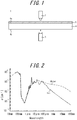
- FIG. 1 is a diagram schematically depicting a water-on-ice height measurement apparatus that can be used for a method of measuring a height of water on ice in accordance with a first embodiment of the present disclosure.
- This apparatus 1 for measuring a height of water on ice includes an emission device 2 that emits terahertz radiation having a frequency of 10 THz or less (preferably, a frequency of 0.1 THz or more and 10 THz or less), and a transmitted radiation measurement device 3 that detects and measures transmitted radiation of the terahertz radiation.
- an emission device 2 that emits terahertz radiation having a frequency of 10 THz or less (preferably, a frequency of 0.1 THz or more and 10 THz or less)
- a transmitted radiation measurement device 3 that detects and measures transmitted radiation of the terahertz radiation.
- the emission device 2 and the transmitted radiation measurement device 3 are disposed so as to face each other, having ice 4 with a first surface 4a and a second surface 4b that is opposite to the first surface 4a interposed therebetween.
- the emission device 2 is disposed outside the ice 4 on the side of the first surface 4a of the ice 4 (above the ice 4 in FIG. 1 )
- the transmitted radiation measurement device 3 is disposed outside the ice 4 on the side of the second surface 4b of the ice 4 (below the ice 4 in FIG. 1 ).
- terahertz radiation having frequency of 10 THz or less (preferably, a frequency of 0.1 THz or more and 10 THz or less) is emitted by the emission device 2 toward the first surface 4a.
- the terahertz radiation passes through water 5 (if present), and then passes through the ice 4, in this order.
- the transmitted radiation of the terahertz radiation is then measured by the transmitted radiation measurement device 3.
- the emission of the terahertz radiation by the emission device 2 and the measurement of the transmitted radiation by the transmitted radiation measurement device 3 are conducted on a line (at a point in plan view) in the depicted example, they may be conducted on a plane or at a point.
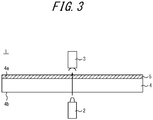
- FIG. 2 is a diagram indicating the relationship between wavelengths of electromagnetic radiation and the absorption properties to ice and water of the electromagnetic radiation (source: The Optical Society of Japan, Japanese Journal of Optics, pp. 485-486, Vol. 36 No. 8 (2007 ), Optical Science and Optical Technology Research Committee).
- source The Optical Society of Japan, Japanese Journal of Optics, pp. 485-486, Vol. 36 No. 8 (2007 ), Optical Science and Optical Technology Research Committee.
- the label “ ⁇ -1 " on the vertical axis indicates the absorptivities of electromagnetic radiation to ice and water.
- the distinguishable differences appear between the absorption properties of electromagnetic radiation of ice and water at wavelengths of terahertz radiation (frequencies of 0.1 THz to 10 THz; i.e., wavelengths of 30 ⁇ m to 3 mm) or longer.
- the intensity of transmitted radiation of the terahertz radiation decreases as water on ice increases.
- the height of the water 5 on the ice 4 can be measured from the above-described measurement result of the transmitted radiation (e.g., the reduction in the intensity thereof).
- a measurement is performed with the method of this embodiment after predetermined time elapses from the initial state where water 5 is absent on the ice 4. If any reduction in the intensity is detected in the measured terahertz radiation (e.g., caused by melting of the ice 4 during the predetermined time), it can be considered that a water film of a certain thickness has been formed. Then, if a similar measurement is performed after the predetermined time and a further reduction is detected in the measured terahertz radiation, it can be considered that the water film has thickened (due to further melting and the like).
- the intensity of terahertz radiation has not demonstrated any reduction after the predetermined time, for example, it can be considered that no water film has been formed (i.e., the height of water is zero).
- the height of water on ice can be measured with a simplified procedure.
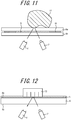
- FIG. 3 is a diagram schematically depicting a water-on-ice height measurement apparatus that can be used for a method of measuring a height of water on ice in accordance with a second embodiment of the present disclosure.
- This measurement apparatus used in the second embodiment is different from that of the first embodiment in that the emission device 2 is disposed outside the ice 4 on the side of the second surface 4b of the ice 4 (below the ice 4 in FIG. 3 ), while the transmitted radiation measurement device 3 is disposed outside the ice 4 on the side of the first surface 4a of the ice 4 (above the ice 4 in FIG. 3 ).
- terahertz radiation having frequency of 10 THz or less (preferably, a frequency of 0.1 THz or more and 10 THz or less) is emitted by the emission device 2 toward the second surface 4b.
- the transmitted radiation of the terahertz radiation is then measured by the transmitted radiation measurement device 3.
- the order of transmissions of the terahertz radiation in the second embodiment is different in that ice 4 is the first and the water 5 (if present) is the next, but the intensity of transmitted radiation of the terahertz radiation reduces as the water 5 increases also in the second embodiment.
- the height of the water on the ice therefore, can be measured with a simplified procedure.
- FIG. 4 is a diagram schematically depicting a water-on-ice height measurement apparatus that can be used for a method of measuring a height of water on ice in accordance with a third embodiment of the present disclosure.
- reflected radiation measurement device 6 is used in place of the transmitted radiation measurement device 3 in the third embodiment, and the third embodiment is different from the first embodiment in that both the emission device 2 and the reflected radiation measurement device 6 are disposed outside the ice 4 on the side of the first surface 4a of the ice 4 (above the ice 4 in FIG. 4 ).
- terahertz radiation having frequency of 10 THz or less (preferably, a frequency of 0.1 THz or more and 10 THz or less) is emitted by the emission device 2 toward the first surface 4a.
- the emitted terahertz radiation passes through water 5 (if present), then enters the ice 4, is reflected by the second surface 4b of the ice 4, and passes through the ice 4 and the water 5 (if present).
- the reflected radiation of the terahertz radiation is then measured by the reflected radiation measurement device 6.
- the intensity of the reflected radiation of the terahertz radiation reduces as the water increases also in the third embodiment.
- the height of the water on the ice therefore, can be measured with a simplified procedure.
- FIG. 5 is a diagram schematically depicting a water-on-ice height measurement apparatus that can be used for a method of measuring a height of water on ice in accordance with a fourth embodiment of the present disclosure.
- the fourth embodiment is different from the third embodiment in that both the emission device 2 and the reflected radiation measurement device 6 are disposed outside the ice 4 on the side of the second surface 4b of the ice 4 (below the ice 4 in FIG. 5 ).
- terahertz radiation having frequency of 10 THz or less (preferably, a frequency of 0.1 THz or more and 10 THz or less) is emitted by the emission device 2 toward the second surface 4b.
- terahertz radiation having frequency of 10 THz or less (preferably, a frequency of 0.1 THz or more and 10 THz or less) is emitted by the emission device 2 toward the second surface 4b.
- the emitted terahertz radiation enters the water 5 from the ice 4, is then reflected by the first surface of the water 5, and passes through the water 5 and the ice 4 again.
- the emitted terahertz radiation would pass through the ice 4 and be reflected by the first surface 4a of the ice 4.
- the reflected radiation of the terahertz radiation is then measured by the radiation measurement device 6.
- the height of the water on the ice can be measured with a simplified procedure similarly to the third embodiment because only the order to pass the ice 4 and the water 5 (if present) is different from that in Example 3.
- the height of the water 5 on the ice 4 can be measured in a simplified manner by emitting terahertz radiation having frequency of 10 THz or less (preferably, a frequency of 0.1 THz or more and 10 THz or less) toward the first surface 4a or the second surface 4b of the ice 4; and measuring the transmitted radiation or reflected radiation of the terahertz radiation to measure the height of the water 5 on the ice 4 from a result of the measurement.
- terahertz radiation is emitted toward the first surface 4a of the ice 4 from outside the side of the second surface 4b of the ice 4, or terahertz radiation is emitted to the first surface 4a from inside the ice 4a, transmitted or reflected radiation of the terahertz radiation is measured to measure the height of the water 5 on the first surface 4a of the ice 4 from a result of the measurement.
- FIGS. 6A and 6B are diagrams schematically depicting a water-on-ice height measurement apparatus used a method of measuring a height of water on ice in accordance with a fourth embodiment of the present disclosure.
- a tire 7 is placed on a first surface 4a of ice 4.
- terahertz radiation is emitted toward the first surface 4a of the ice 4 by the emission device 2 from outside the side of the second surface 4b of the ice 4 (the bottom part of FIG. 6A ) while the tire 7 is placed on the first surface 4a of the ice 4.
- the emitted terahertz radiation passes through the ice 4, then passes through the water 5 (if present), and is reflected by the tire 7.
- the reflected radiation of terahertz radiation passes through water 5 (if present) and the ice 4 in this order.
- the reflected radiation of the terahertz radiation from the tire 7 is then measured by the reflected radiation measurement device 6 to measure the height of the water 5 between the ice 4 and the tire 7 from a result of the measurement.
- the height of the water 5 that is present between the ice 4 and the tire 7 can be measured.
- FIG. 6B is different from FIG. 6A in that a rubber block 8 is placed on a first surface 4a of the ice 4. Similar advantageous effects can be achieved with the rubber block 8 by the similar technique to the technique with the tire 7 in FIG. 6A .
- terahertz radiation is emitted toward the first surface 4a of the ice 4 from outside the side of the second surface 4b of the ice 4 or terahertz radiation is emitted toward the first surface 4a from inside the ice 4 while an object is placed on the first surface 4a of the ice 4, the reflected radiation of the terahertz radiation from the object is measured to measure the height of the water 5 between the ice 4 and the object from a result of the measurement.
- the object is preferably made from a rubber. This is preferred because the height of the water 5 that is present between the ice 4 and the rubber can be measured. Furthermore, in the present disclosure, the object is preferably one of a tire, a rubber block, and a rubber sheet. This is preferred because the height of the water 5 that is present between the ice 4 and one of the tire 7, the rubber block 8, and the rubber sheet can be measured.
- the tire 7 can be displaced relative to the ice 4.
- the above-described measurement may be performed while the ice 4 is being displaced and the tire 7 rotatable about the tire axis is kept at rest. This enables a measurement of the thickness of a water film when the tire 7 rolls on the ice 4.
- the ice 4 may be kept at rest, and the tire 7 may be rotated or displaced such that the tire 7 rolls on the ice 4.
- the tire 7 may be rotated or displaced while the ice 4 is being displaced.
- the emission device 2 and the reflected radiation measurement device 6 may be fixed or may be displaced.
- any of well-known apparatuses may be used to displace or rotate the tire 7, the ice 4, the emission device 2, or the reflected radiation measurement device 6.
- the rubber block 8 may be displaced relative to the ice 4.
- the above-described measurement may be performed while the ice 4 is being displaced and the rubber block 8 is kept at rest. This enables the thickness of water film to be measured when the rubber block 8 moves on the ice 4.
- the ice 4 may be kept at rest, and the rubber block 8 may be displaced.
- the rubber block may be displaced while the ice 4 is being displaced.
- the emission device 2 and the reflected radiation measurement device 6 may be fixed or may be displaced.
- any of well-known apparatuses may be used to displace the rubber block 8, the ice 4, the emission device 2 or the reflected radiation measurement device 6. This is also applicable to the rubber sheet or any other objects.
- FIGS. 7 and 8 are schematic diagrams for illustrating how to obtain the relationship between the height of water and the intensity of transmitted radiation of terahertz radiation in advance.
- transparent plates 9a, 9b transparent to terahertz radiation are disposed so as to face each other, having spacers 10 sandwiched between the transparent plates 9a, 9b.
- the transparent plates 9a, 9b plates made from glass and an acrylic, and a polycarbonate, and plate-like ice are used, for example.
- Air 11 is present inside the space enclosed by the transparent plates 9a, 9b and the spacers 10.
- the terahertz-wave emission device 2 is disposed outside the ice 4 on the side of the transparent plate 9b, and the transmitted radiation measurement device 3 is disposed outside the ice 4 on the side of the transparent plate 9a.
- the emission device 2 may be disposed outside the ice 4 on the side of the transparent plate 9a, and the transmitted radiation measurement device 3 may be disposed outside the ice 4 on the side of the transparent plate 9b.
- Terahertz radiation is then emitted by the emission device 2, and the intensity of transmitted radiation of the terahertz radiation in the absence of water is measured by the transmitted radiation measurement device 3 in advance.
- the space enclosed by the transparent plates 9a, 9b and the spacers 10 is filled with water 5.
- the water 5 is filled to the height equal to the thickness of the spacers 10, and accordingly the height of the water 5 can be adjusted by adjusting the thickness of the spacers 10.
- Terahertz radiation is then emitted by the emission device 2, and the intensity of transmitted radiation of the terahertz radiation is measured by the transmitted radiation measurement device 3 in the presence of water in a known height (the height same as that of the spacers 10). Then, by determining the difference between the intensities of the transmitted radiation of the terahertz radiation in the two cases in FIGS.
- the reduction in the intensity of the transmitted radiation of the terahertz radiation in the presence of the water 5 of the known height can be determined.
- the spacers 10 of different thicknesses may be provided and reductions in the intensity of the transmitted radiation of the terahertz radiation may be determined for various heights of the water 5, from the viewpoint of enhancing the accuracy of measurements of the height of the water 5.
- FIG. 9 is a diagram indicating the relationship between the height of water and a reduction rate of the intensity of transmitted radiation of terahertz radiation.
- the relationship between the height of water and a reduction rate of the intensity of transmitted radiation of terahertz radiation as the one depicted in FIG. 9 can be obtained using the technique depicted in FIGS. 7 and 8 .
- an absolute value of the height of the water 5 on the ice 4 can then be calculated based on an intensity of transmitted radiation of terahertz radiation measured and this relationship.
- FIGS. 10 and 11 are schematic diagrams for illustrating how to obtain the relationship between the height of water and the intensity of reflected radiation of terahertz radiation.
- the transparent plates 9a, 9b transparent to terahertz radiation are disposed so as to face each other, having the spacers 10 sandwiched between the transparent plates 9a, 9b.
- Air 11 is present inside the space enclosed by the transparent plates 9a, 9b and the spacers 10.
- An object 12 is placed on one transparent plate 9a.
- both the terahertz-wave emission device 2 and the reflected radiation measurement device 6 are disposed outside the ice 4 on the side of the transparent plate 9b.
- Terahertz radiation is then emitted by the emission device 2, and the intensity of reflected radiation of the terahertz radiation in the absence of water is measured by the reflected radiation measurement device 6 in advance.
- the space enclosed by the transparent plates 9a, 9b and the spacers 10 is filled with the water 5.
- the water 5 is filled to the height equal to the thickness of the spacers 10, and accordingly the height of the water 5 can be adjusted by adjusting the thickness of the spacers 10.
- Terahertz radiation is then emitted by the emission device 2, and the intensity of reflected radiation of the terahertz radiation is measured by the reflected radiation measurement device 6 in the presence of water of known height (the height same as that of the spacers 10). Then, by determining the difference between the intensities of the reflected radiation of the terahertz radiation in the two cases in FIGS.
- the reduction in the intensity of the reflected radiation of the terahertz radiation reflected by the object 12 in the presence of the water 5 of the known height can be obtained.
- the spacers 10 of different thicknesses may be provided and reductions in the intensity of the reflected radiation of the terahertz radiation may be measured for various heights of the water 5, from the viewpoint of enhancing the accuracy of measurements of the height of the water 5.
- the object 12 is preferably any of objects those used in actual measurements, such as the tire 7 or the rubber block 8 as in the fourth embodiment, for example, and the object 12 preferably has the same surface roughness (this is applicable to examples in FIGS. 7 and 8 ). Note that this technique can be used without the object 12.
- the sum of the thicknesses of the transparent plates 9a, 9b is preferably set to be equal to the thickness of ice 4 in actual measurements.
- the frequency of terahertz radiation is preferably set to be the same as that used in actual measurements.
- the intensity of terahertz radiation preferably is set to be the same as that used in actual measurements.
- Total thickness of transparent plates Thickness of ice used in measurement ⁇ transmittance to ice / transmittance to transparent plate
- an absolute value of the height of the water 5 on the ice 4 can be calculated more easily based on the measured intensity of reflected radiation of terahertz radiation and that relationship.
- terahertz radiation having a frequency of 10 THz or less (preferably, a frequency of 0.1 THz to 10 THz) is emitted toward the first surface 4a of the ice 4 or the second surface 4b of the ice 4, reflected radiation of the terahertz radiation is measured, and an intensity of the reflected radiation is measured to measure the height of the water 5 on the ice 4 from a result of the measurement. This is preferred because the height of water on ice can be calculated more easily.
- the relationship between the height of water 5 and the intensity of transmitted or reflected radiation of terahertz radiation is obtained in advance, by emitting terahertz radiation to water 5 in a known height, and measuring the intensity of transmitted or reflected radiation of the terahertz radiation to measure the height of water 5 on the ice 4 using the relationship obtained in advance.
- This is preferred because an absolute value of the height of the water on ice can be calculated.
- arrival time of reflected radiation is measured to measure the height of water 5 on the ice 4 from the speed of the terahertz radiation and the measured arrival time.
- the height of the water on the ice can also be measured further easily with this method.
- the height of the water 5 can be measured in the example depicted in FIG. 6A by determining the difference between arrival time of reflected radiation from the tire 7 and arrival time of reflected radiation from the first surface 4a of the ice 4. This is preferred because the difference in the arrival time (time until reflected radiation is received) is caused by the difference in the traveling distance.
- measurements are performed by changing frequencies of terahertz radiation such that the measurement result include measurement results of the terahertz radiation of different frequencies. This is preferred because the height of water on ice can be measured more precisely by using the results of multiple frequencies.
- the wavelength of terahertz radiation is preferably selected according to the size of water subjected to a height measurement.
- the frequency of terahertz radiation may be set to about 1 THz.
- terahertz radiation with a higher frequency may be used.
- terahertz radiation with a lower frequency may be used.
- terahertz radiation with a higher frequency may be used to provide a higher resolution.
- terahertz radiation with a higher frequency may be used for measuring the thickness of a water film in the vicinity of a sipe in a block of a tire tread of the tire 7, a block edge, a small area divided by sipes, and the like.
- FIG. 12 is a diagram for illustrating Examples of the present disclosure.
- a studless tire having a tire size of PSR195/65R15 was fabricated.
- a block of a tire tread of this studless tire had a width of 20 mm and a length of 25 mm in top view, the groove depth was 9 mm, the sipe depth was 5 mm, and the sipe width was 0.5 mm.
- the number of sipes is four, and the sipes were arranged at regular intervals of 6.25 mm.
- the tire was cut to the groove depth to obtain a single siped block 13.
- the siped block 13 was placed on plate-like ice 4 in 20 mm thick.
- Example 1 1-THz terahertz radiation was emitted to a point by the emission device 2, and reflected radiation of the terahertz radiation from that point was measured by the reflected radiation measurement device 6.
- Example 2 0.5-THz terahertz radiation was emitted to a point by the emission device 2, and reflected radiation of the terahertz radiation from that point was measured by the reflected radiation measurement device 6.
- Example 3 1-THz terahertz radiation was emitted on a plane by the emission device 2, and reflected radiation of the terahertz radiation on that plane was measured by the reflected radiation measurement device 6.
- Example 1 Intensity of reflected radiation reduced
- Example 2 Intensity of reflected radiation reduced as compared to reduction in Example 1
- Example 3 Intensity of reflected radiation reduced particularly at rear of forward direction of block
- Example 1 As indicated in Table 1, in Conventional Example, no difference was observed between the intensities of emitted light and reflected light, and presence of water was not confirmed. In contrast, in Example 1, the reduction in the intensity of the reflected radiation indicated an increased height of water. Further, in Example 2, the reduction in the intensity of the reflected radiation greater than the reduction in Example 1 indicated a further increase in the height of water as compared to Example 1. Further, in Example 3, the result of the observation on the plane with emitted terahertz radiation at 1 THz indicated that the intensity of the reflected radiation reduced at the particular location of the rear of the forward direction of the block, suggesting that the height of water increased at that location. Because water 5 was absent on the ice 4 at the initial stage in the conditions in Examples 1-3, it is considered that a water film was formed between the ice 4 and the siped block 13 by the slid of the siped block 13 on the ice 4.
- the present disclosure is applicable to determine the thickness of a water film in on-ice behavior tests.
- the present disclosure may be used to determine the thickness of a water film on ice on actual road surfaces.
Landscapes
- Physics & Mathematics (AREA)
- Spectroscopy & Molecular Physics (AREA)
- General Physics & Mathematics (AREA)
- Health & Medical Sciences (AREA)
- Biochemistry (AREA)
- Analytical Chemistry (AREA)
- Chemical & Material Sciences (AREA)
- General Health & Medical Sciences (AREA)
- Life Sciences & Earth Sciences (AREA)
- Immunology (AREA)
- Pathology (AREA)
- Toxicology (AREA)
- Length Measuring Devices By Optical Means (AREA)
- Length-Measuring Devices Using Wave Or Particle Radiation (AREA)
- Length Measuring Devices Characterised By Use Of Acoustic Means (AREA)
Abstract
Description
- The present disclosure relates to a method of measuring a height of water on ice.
- As a technique to measure the height of water on a road surface, a method is known which includes emitting electromagnetic radiation toward the road surface and measuring the height of water on the road surface from the attenuation of the electromagnetic radiation (for example, see Patent Literature 1).
- Patent Literature (PTL) 1:
JP 4176586 B - The above-described technique, however, has a difficulty in distinguishing substances having similar dielectric constants, such as ice and water, for example, and detecting water by distinguishing ice and water that are present on the road surface was difficult. In addition, ice and water also have similar indices of refraction of light, and hence distinguishing them using visible light is also difficult. Furthermore, when a water film on ice is thin, distinguishing them is difficult even with ultrasonic waves.
- In light of such a background, an object of the present disclosure is to provide a method of measuring a height of water on ice which makes measurements of the height of water on ice possible with a simplified procedure.
- The subject matter of the present disclosure is as follows:
A method of measuring a height of water on ice of the present disclosure comprises emitting terahertz radiation having a frequency of 10 THz or less toward a first surface of the ice; and measuring transmitted or reflected radiation of the terahertz radiation to measure the height of the water on the ice from a result of the measurement. - As used therein, the term "measuring a height of water on ice" includes obtaining a measurement result of the height of water of zero in the absence of water, and also includes determining the relative relationship of heights and detecting the presence or absence of water on ice, as well as obtaining the value of the height.
- In accordance with the present disclosure, a method of measuring a height of water on ice is provided which makes measurements of the height of water on ice possible with a simplified procedure.
- In the accompanying drawings:
-
FIG. 1 is a diagram schematically depicting a water-on-ice height measurement apparatus that can be used for a method of measuring a height of water on ice in accordance with a first embodiment of the present disclosure; -
FIG. 2 is a diagram indicating the relationship between wavelengths of electromagnetic radiation and the absorption properties to ice and water of the electromagnetic radiation; -
FIG. 3 is a diagram schematically depicting a water-on-ice height measurement apparatus that can be used for a method of measuring a height of water on ice in accordance with a second embodiment of the present disclosure; -
FIG. 4 is a diagram schematically depicting a water-on-ice height measurement apparatus that can be used for a method of measuring a height of water on ice in accordance with a third embodiment of the present disclosure; -
FIG. 5 is a schematic diagram for illustrating a measurement of a height of water on ice using a water-on-ice height measurement apparatus that can be used for a method of measuring a height of water on ice, in accordance with a fourth embodiment of the present disclosure; -
FIGS. 6A and 6B are diagrams schematically depicting a water-on-ice height measurement apparatus that can be used for a method of measuring a height of water on ice accordance with the fourth embodiment of the present disclosure; -
FIG. 7 is a schematic diagram for illustrating how to obtain the relationship between the height of water and the intensity of transmitted radiation of terahertz radiation in advance; -
FIG. 8 is a schematic diagram for illustrating how to obtain the relationship between the height of water and the intensity of transmitted radiation of terahertz radiation in advance; -
FIG. 9 is a diagram indicating the relationship between the height of water and a reduction rate of the intensity of transmitted radiation of terahertz radiation; -
FIG. 10 is a schematic diagram for illustrating how to obtain the relationship between the height of water and the intensity of reflected radiation of terahertz radiation; -
FIG. 11 is a schematic diagram for illustrating how to obtain the relationship between the height of water and the intensity of reflected radiation of terahertz radiation; and -
FIG. 12 is a diagram for illustrating Examples of the present disclosure. - Hereinafter, embodiments of the present disclosure will be described with reference to the drawings.
-
FIG. 1 is a diagram schematically depicting a water-on-ice height measurement apparatus that can be used for a method of measuring a height of water on ice in accordance with a first embodiment of the present disclosure. Thisapparatus 1 for measuring a height of water on ice includes anemission device 2 that emits terahertz radiation having a frequency of 10 THz or less (preferably, a frequency of 0.1 THz or more and 10 THz or less), and a transmittedradiation measurement device 3 that detects and measures transmitted radiation of the terahertz radiation. In the embodiment depicted inFIG. 1 , theemission device 2 and the transmittedradiation measurement device 3 are disposed so as to face each other, havingice 4 with afirst surface 4a and asecond surface 4b that is opposite to thefirst surface 4a interposed therebetween. In other words, in the embodiment depicted inFIG. 1 , theemission device 2 is disposed outside theice 4 on the side of thefirst surface 4a of the ice 4 (above theice 4 inFIG. 1 ), whereas the transmittedradiation measurement device 3 is disposed outside theice 4 on the side of thesecond surface 4b of the ice 4 (below theice 4 inFIG. 1 ). In the method of the first embodiment, terahertz radiation having frequency of 10 THz or less (preferably, a frequency of 0.1 THz or more and 10 THz or less) is emitted by theemission device 2 toward thefirst surface 4a. The terahertz radiation passes through water 5 (if present), and then passes through theice 4, in this order. The transmitted radiation of the terahertz radiation is then measured by the transmittedradiation measurement device 3. Although the emission of the terahertz radiation by theemission device 2 and the measurement of the transmitted radiation by the transmittedradiation measurement device 3 are conducted on a line (at a point in plan view) in the depicted example, they may be conducted on a plane or at a point. This is also applicable to second to fourth embodiments described below (note that a measurement is performed by the transmittedradiation measurement device 3 in a second embodiment whereas measurements are performed by reflectedradiation measurement device 6 that detects and measures reflected radiation of terahertz radiation in third to fourth embodiments). Note that, when a measurement is performed on a line or on a plane, the measurement may be performed entirely or locally. For example, when the heights are measured entirely, appropriate calculations may be performed, including determining the average, the maximum, or the minimum. -
FIG. 2 is a diagram indicating the relationship between wavelengths of electromagnetic radiation and the absorption properties to ice and water of the electromagnetic radiation (source: The Optical Society of Japan, Japanese Journal of Optics, pp. 485-486, Vol. 36 No. 8 (2007), Optical Science and Optical Technology Research Committee). InFIG. 2 , the label "α-1" on the vertical axis indicates the absorptivities of electromagnetic radiation to ice and water. As depicted inFIG. 2 , while there is no difference in the absorption properties in the wavelength region of 360 nm to 830 nm, which is the wavelength region of visible light, the distinguishable differences appear between the absorption properties of electromagnetic radiation of ice and water at wavelengths of terahertz radiation (frequencies of 0.1 THz to 10 THz; i.e., wavelengths of 30 µm to 3 mm) or longer. In other words, the intensity of transmitted radiation of the terahertz radiation decreases as water on ice increases. Hence, in accordance with the first embodiment, the height of thewater 5 on theice 4 can be measured from the above-described measurement result of the transmitted radiation (e.g., the reduction in the intensity thereof). For example, a measurement is performed with the method of this embodiment after predetermined time elapses from the initial state wherewater 5 is absent on theice 4. If any reduction in the intensity is detected in the measured terahertz radiation (e.g., caused by melting of theice 4 during the predetermined time), it can be considered that a water film of a certain thickness has been formed. Then, if a similar measurement is performed after the predetermined time and a further reduction is detected in the measured terahertz radiation, it can be considered that the water film has thickened (due to further melting and the like). On the other hand, if the intensity of terahertz radiation has not demonstrated any reduction after the predetermined time, for example, it can be considered that no water film has been formed (i.e., the height of water is zero). Thus, in accordance with the method of measuring a height of water on ice of this embodiment, the height of water on ice can be measured with a simplified procedure. -
FIG. 3 is a diagram schematically depicting a water-on-ice height measurement apparatus that can be used for a method of measuring a height of water on ice in accordance with a second embodiment of the present disclosure. This measurement apparatus used in the second embodiment is different from that of the first embodiment in that theemission device 2 is disposed outside theice 4 on the side of thesecond surface 4b of the ice 4 (below theice 4 inFIG. 3 ), while the transmittedradiation measurement device 3 is disposed outside theice 4 on the side of thefirst surface 4a of the ice 4 (above theice 4 inFIG. 3 ). In the second embodiment, terahertz radiation having frequency of 10 THz or less (preferably, a frequency of 0.1 THz or more and 10 THz or less) is emitted by theemission device 2 toward thesecond surface 4b. The transmitted radiation of the terahertz radiation is then measured by the transmittedradiation measurement device 3. The order of transmissions of the terahertz radiation in the second embodiment is different in thatice 4 is the first and the water 5 (if present) is the next, but the intensity of transmitted radiation of the terahertz radiation reduces as thewater 5 increases also in the second embodiment. Similarly to the first embodiment, the height of the water on the ice, therefore, can be measured with a simplified procedure. -
FIG. 4 is a diagram schematically depicting a water-on-ice height measurement apparatus that can be used for a method of measuring a height of water on ice in accordance with a third embodiment of the present disclosure. As depicted inFIG. 4 , reflectedradiation measurement device 6 is used in place of the transmittedradiation measurement device 3 in the third embodiment, and the third embodiment is different from the first embodiment in that both theemission device 2 and the reflectedradiation measurement device 6 are disposed outside theice 4 on the side of thefirst surface 4a of the ice 4 (above theice 4 inFIG. 4 ). In the third embodiment, terahertz radiation having frequency of 10 THz or less (preferably, a frequency of 0.1 THz or more and 10 THz or less) is emitted by theemission device 2 toward thefirst surface 4a. As depicted inFIG. 4 , the emitted terahertz radiation passes through water 5 (if present), then enters theice 4, is reflected by thesecond surface 4b of theice 4, and passes through theice 4 and the water 5 (if present). The reflected radiation of the terahertz radiation is then measured by the reflectedradiation measurement device 6. Although the terahertz radiation passes through theice 4 and the water 5 (if present) twice, the intensity of the reflected radiation of the terahertz radiation reduces as the water increases also in the third embodiment. Similarly to the first embodiment, the height of the water on the ice, therefore, can be measured with a simplified procedure. -
FIG. 5 is a diagram schematically depicting a water-on-ice height measurement apparatus that can be used for a method of measuring a height of water on ice in accordance with a fourth embodiment of the present disclosure. As depicted inFIG. 5 , the fourth embodiment is different from the third embodiment in that both theemission device 2 and the reflectedradiation measurement device 6 are disposed outside theice 4 on the side of thesecond surface 4b of the ice 4 (below theice 4 inFIG. 5 ). In the fourth embodiment, terahertz radiation having frequency of 10 THz or less (preferably, a frequency of 0.1 THz or more and 10 THz or less) is emitted by theemission device 2 toward thesecond surface 4b. As depicted inFIG. 5 , in the presence ofwater 5, the emitted terahertz radiation enters thewater 5 from theice 4, is then reflected by the first surface of thewater 5, and passes through thewater 5 and theice 4 again. Note that, ifwater 5 is not present, the emitted terahertz radiation would pass through theice 4 and be reflected by thefirst surface 4a of theice 4. The reflected radiation of the terahertz radiation is then measured by theradiation measurement device 6. In the fourth embodiment, the height of the water on the ice can be measured with a simplified procedure similarly to the third embodiment because only the order to pass theice 4 and the water 5 (if present) is different from that in Example 3. - As in the first to fourth embodiments, the height of the
water 5 on theice 4 can be measured in a simplified manner by emitting terahertz radiation having frequency of 10 THz or less (preferably, a frequency of 0.1 THz or more and 10 THz or less) toward thefirst surface 4a or thesecond surface 4b of theice 4; and measuring the transmitted radiation or reflected radiation of the terahertz radiation to measure the height of thewater 5 on theice 4 from a result of the measurement. - In the present disclosure, preferably, terahertz radiation is emitted toward the
first surface 4a of theice 4 from outside the side of thesecond surface 4b of theice 4, or terahertz radiation is emitted to thefirst surface 4a from inside theice 4a, transmitted or reflected radiation of the terahertz radiation is measured to measure the height of thewater 5 on thefirst surface 4a of theice 4 from a result of the measurement. -
FIGS. 6A and 6B are diagrams schematically depicting a water-on-ice height measurement apparatus used a method of measuring a height of water on ice in accordance with a fourth embodiment of the present disclosure. InFIG. 6A , atire 7 is placed on afirst surface 4a ofice 4. In the embodiment depicted inFIG. 6A , terahertz radiation is emitted toward thefirst surface 4a of theice 4 by theemission device 2 from outside the side of thesecond surface 4b of the ice 4 (the bottom part ofFIG. 6A ) while thetire 7 is placed on thefirst surface 4a of theice 4. The emitted terahertz radiation passes through theice 4, then passes through the water 5 (if present), and is reflected by thetire 7. The reflected radiation of terahertz radiation passes through water 5 (if present) and theice 4 in this order. The reflected radiation of the terahertz radiation from thetire 7 is then measured by the reflectedradiation measurement device 6 to measure the height of thewater 5 between theice 4 and thetire 7 from a result of the measurement. In accordance with the embodiment depicted inFIG. 6A , the height of thewater 5 that is present between theice 4 and thetire 7 can be measured. -
FIG. 6B is different fromFIG. 6A in that arubber block 8 is placed on afirst surface 4a of theice 4. Similar advantageous effects can be achieved with therubber block 8 by the similar technique to the technique with thetire 7 inFIG. 6A . - In the second and fourth embodiments, similar advantageous effects can be achieved by emitting terahertz radiation to the
first surface 4a of theice 4 from inside theice 4, such as by disposing theemission device 2 inside theice 4. - As in the embodiments depicted in
FIGS. 6A and 6B , in the present disclosure, upon measuring the height of water between an object and ice, preferably, terahertz radiation is emitted toward thefirst surface 4a of theice 4 from outside the side of thesecond surface 4b of theice 4 or terahertz radiation is emitted toward thefirst surface 4a from inside theice 4 while an object is placed on thefirst surface 4a of theice 4, the reflected radiation of the terahertz radiation from the object is measured to measure the height of thewater 5 between theice 4 and the object from a result of the measurement. This is preferred because the height of thewater 5 that is present between theice 4 and the object can be measured. In the present disclosure, the object is preferably made from a rubber. This is preferred because the height of thewater 5 that is present between theice 4 and the rubber can be measured. Furthermore, in the present disclosure, the object is preferably one of a tire, a rubber block, and a rubber sheet. This is preferred because the height of thewater 5 that is present between theice 4 and one of thetire 7, therubber block 8, and the rubber sheet can be measured. - In the embodiment depicted in
FIG. 6A , thetire 7 can be displaced relative to theice 4. For example, the above-described measurement may be performed while theice 4 is being displaced and thetire 7 rotatable about the tire axis is kept at rest. This enables a measurement of the thickness of a water film when thetire 7 rolls on theice 4. As a matter of course, theice 4 may be kept at rest, and thetire 7 may be rotated or displaced such that thetire 7 rolls on theice 4. Alternatively, thetire 7 may be rotated or displaced while theice 4 is being displaced. In any case, theemission device 2 and the reflectedradiation measurement device 6 may be fixed or may be displaced. In these cases, any of well-known apparatuses may be used to displace or rotate thetire 7, theice 4, theemission device 2, or the reflectedradiation measurement device 6. In the embodiment depicted inFIG. 6B , therubber block 8 may be displaced relative to theice 4. For example, the above-described measurement may be performed while theice 4 is being displaced and therubber block 8 is kept at rest. This enables the thickness of water film to be measured when therubber block 8 moves on theice 4. As a matter of course, theice 4 may be kept at rest, and therubber block 8 may be displaced. Alternatively, the rubber block may be displaced while theice 4 is being displaced. In any case, theemission device 2 and the reflectedradiation measurement device 6 may be fixed or may be displaced. In these cases, any of well-known apparatuses may be used to displace therubber block 8, theice 4, theemission device 2 or the reflectedradiation measurement device 6. This is also applicable to the rubber sheet or any other objects. -
FIGS. 7 and 8 are schematic diagrams for illustrating how to obtain the relationship between the height of water and the intensity of transmitted radiation of terahertz radiation in advance. As depicted inFIG. 7 ,transparent plates spacers 10 sandwiched between thetransparent plates transparent plates Air 11 is present inside the space enclosed by thetransparent plates spacers 10. In the illustrated example, the terahertz-wave emission device 2 is disposed outside theice 4 on the side of thetransparent plate 9b, and the transmittedradiation measurement device 3 is disposed outside theice 4 on the side of thetransparent plate 9a. Alternatively, theemission device 2 may be disposed outside theice 4 on the side of thetransparent plate 9a, and the transmittedradiation measurement device 3 may be disposed outside theice 4 on the side of thetransparent plate 9b. Terahertz radiation is then emitted by theemission device 2, and the intensity of transmitted radiation of the terahertz radiation in the absence of water is measured by the transmittedradiation measurement device 3 in advance. - Next, as depicted in
FIG. 8 , the space enclosed by thetransparent plates spacers 10 is filled withwater 5. Thewater 5 is filled to the height equal to the thickness of thespacers 10, and accordingly the height of thewater 5 can be adjusted by adjusting the thickness of thespacers 10. Terahertz radiation is then emitted by theemission device 2, and the intensity of transmitted radiation of the terahertz radiation is measured by the transmittedradiation measurement device 3 in the presence of water in a known height (the height same as that of the spacers 10). Then, by determining the difference between the intensities of the transmitted radiation of the terahertz radiation in the two cases inFIGS. 7 and 8 , the reduction in the intensity of the transmitted radiation of the terahertz radiation in the presence of thewater 5 of the known height can be determined. Note that, preferably, thespacers 10 of different thicknesses may be provided and reductions in the intensity of the transmitted radiation of the terahertz radiation may be determined for various heights of thewater 5, from the viewpoint of enhancing the accuracy of measurements of the height of thewater 5. -
FIG. 9 is a diagram indicating the relationship between the height of water and a reduction rate of the intensity of transmitted radiation of terahertz radiation. As one example, the relationship between the height of water and a reduction rate of the intensity of transmitted radiation of terahertz radiation as the one depicted inFIG. 9 can be obtained using the technique depicted inFIGS. 7 and 8 . In the first and third embodiments, an absolute value of the height of thewater 5 on theice 4 can then be calculated based on an intensity of transmitted radiation of terahertz radiation measured and this relationship. -
FIGS. 10 and11 are schematic diagrams for illustrating how to obtain the relationship between the height of water and the intensity of reflected radiation of terahertz radiation. As depicted inFIG. 10 , thetransparent plates spacers 10 sandwiched between thetransparent plates Air 11 is present inside the space enclosed by thetransparent plates spacers 10. Anobject 12 is placed on onetransparent plate 9a. In the illustrated example, both the terahertz-wave emission device 2 and the reflectedradiation measurement device 6 are disposed outside theice 4 on the side of thetransparent plate 9b. Terahertz radiation is then emitted by theemission device 2, and the intensity of reflected radiation of the terahertz radiation in the absence of water is measured by the reflectedradiation measurement device 6 in advance. - Next, as depicted in
FIG. 11 , the space enclosed by thetransparent plates spacers 10 is filled with thewater 5. Thewater 5 is filled to the height equal to the thickness of thespacers 10, and accordingly the height of thewater 5 can be adjusted by adjusting the thickness of thespacers 10. Terahertz radiation is then emitted by theemission device 2, and the intensity of reflected radiation of the terahertz radiation is measured by the reflectedradiation measurement device 6 in the presence of water of known height (the height same as that of the spacers 10). Then, by determining the difference between the intensities of the reflected radiation of the terahertz radiation in the two cases inFIGS. 10 and11 , the reduction in the intensity of the reflected radiation of the terahertz radiation reflected by theobject 12 in the presence of thewater 5 of the known height can be obtained. Note that, preferably, thespacers 10 of different thicknesses may be provided and reductions in the intensity of the reflected radiation of the terahertz radiation may be measured for various heights of thewater 5, from the viewpoint of enhancing the accuracy of measurements of the height of thewater 5. Theobject 12 is preferably any of objects those used in actual measurements, such as thetire 7 or therubber block 8 as in the fourth embodiment, for example, and theobject 12 preferably has the same surface roughness (this is applicable to examples inFIGS. 7 and 8 ). Note that this technique can be used without theobject 12. In addition, when plate-like ice is used as thetransparent plates transparent plates ice 4 in actual measurements. When objects other than ice are used as thetransparent plates ice 4 and thetransparent plates FIG. 2 , the frequency of terahertz radiation is preferably set to be the same as that used in actual measurements. Similarly, the intensity of terahertz radiation preferably is set to be the same as that used in actual measurements.
- In this manner, the relationship between the height of water and a reduction rate of the intensity of reflected radiation of terahertz radiation can be obtained. In the second, fourth, and fifth embodiments, an absolute value of the height of the
water 5 on theice 4 can be calculated more easily based on the measured intensity of reflected radiation of terahertz radiation and that relationship. - As described above, in the present disclosure, preferably, terahertz radiation having a frequency of 10 THz or less (preferably, a frequency of 0.1 THz to 10 THz) is emitted toward the
first surface 4a of theice 4 or thesecond surface 4b of theice 4, reflected radiation of the terahertz radiation is measured, and an intensity of the reflected radiation is measured to measure the height of thewater 5 on theice 4 from a result of the measurement. This is preferred because the height of water on ice can be calculated more easily. - Further, in the present disclosure, preferably, the relationship between the height of
water 5 and the intensity of transmitted or reflected radiation of terahertz radiation is obtained in advance, by emitting terahertz radiation towater 5 in a known height, and measuring the intensity of transmitted or reflected radiation of the terahertz radiation to measure the height ofwater 5 on theice 4 using the relationship obtained in advance. This is preferred because an absolute value of the height of the water on ice can be calculated. - Alternatively, in the present disclosure, preferably, arrival time of reflected radiation is measured to measure the height of
water 5 on theice 4 from the speed of the terahertz radiation and the measured arrival time. This is preferred because the height of the water on the ice can also be measured further easily with this method. For example, the height of thewater 5 can be measured in the example depicted inFIG. 6A by determining the difference between arrival time of reflected radiation from thetire 7 and arrival time of reflected radiation from thefirst surface 4a of theice 4. This is preferred because the difference in the arrival time (time until reflected radiation is received) is caused by the difference in the traveling distance. - Further, in the present disclosure, preferably, measurements are performed by changing frequencies of terahertz radiation such that the measurement result include measurement results of the terahertz radiation of different frequencies. This is preferred because the height of water on ice can be measured more precisely by using the results of multiple frequencies.
- Here, the minimum measurable height increases as the wavelength of terahertz radiation becomes longer. On the other hand, the difference in absorptivity of terahertz radiation between ice and water increases as the wavelength of terahertz radiation becomes longer, as depicted in
FIG. 2 . Accordingly, in the method of the present disclosure, the wavelength of terahertz radiation is preferably selected according to the size of water subjected to a height measurement. For example, for measuring water of a size of about 0.3 mm, the frequency of terahertz radiation may be set to about 1 THz. For measuring water in a size smaller than this size, terahertz radiation with a higher frequency may be used. For example, for observing the trend on the entire surface, terahertz radiation with a lower frequency may be used. In contrast, for observing details, terahertz radiation with a higher frequency may be used to provide a higher resolution. For example, in the example depicted inFIG. 6A , for measuring the thickness of a water film in the vicinity of a sipe in a block of a tire tread of thetire 7, a block edge, a small area divided by sipes, and the like, terahertz radiation with a higher frequency may be used. -
FIG. 12 is a diagram for illustrating Examples of the present disclosure. A studless tire having a tire size of PSR195/65R15 was fabricated. A block of a tire tread of this studless tire had a width of 20 mm and a length of 25 mm in top view, the groove depth was 9 mm, the sipe depth was 5 mm, and the sipe width was 0.5 mm. The number of sipes is four, and the sipes were arranged at regular intervals of 6.25 mm. The tire was cut to the groove depth to obtain asingle siped block 13. Thesiped block 13 was placed on plate-like ice 4 in 20 mm thick. Room temperature and the temperature of the ice were kept to -2°C, and a 100-N load was applied on thesiped block 13. Initially, thesiped block 13 was pressed against the plate-like ice 4, and then the plate-like ice 4 was displaced at a speed of 10 km/h while thesiped block 13 was kept at rest to slide thesiped block 13 on the plate-like ice 4 for 10 seconds. - As Comparative Example, visible light was emitted from below the plate-
like ice 4 and reflected light was recorded with a video camera. In Example 1, 1-THz terahertz radiation was emitted to a point by theemission device 2, and reflected radiation of the terahertz radiation from that point was measured by the reflectedradiation measurement device 6. In Example 2, 0.5-THz terahertz radiation was emitted to a point by theemission device 2, and reflected radiation of the terahertz radiation from that point was measured by the reflectedradiation measurement device 6. In Example 3, 1-THz terahertz radiation was emitted on a plane by theemission device 2, and reflected radiation of the terahertz radiation on that plane was measured by the reflectedradiation measurement device 6. In Examples 1-3, the intensities of the reflected radiation of the terahertz radiation were measured.[Table 1] Measurement results Comparative Example No difference was observed between intensities of emitted light and reflected light Example 1 Intensity of reflected radiation reduced Example 2 Intensity of reflected radiation reduced as compared to reduction in Example 1 Example 3 Intensity of reflected radiation reduced particularly at rear of forward direction of block - As indicated in Table 1, in Conventional Example, no difference was observed between the intensities of emitted light and reflected light, and presence of water was not confirmed. In contrast, in Example 1, the reduction in the intensity of the reflected radiation indicated an increased height of water. Further, in Example 2, the reduction in the intensity of the reflected radiation greater than the reduction in Example 1 indicated a further increase in the height of water as compared to Example 1. Further, in Example 3, the result of the observation on the plane with emitted terahertz radiation at 1 THz indicated that the intensity of the reflected radiation reduced at the particular location of the rear of the forward direction of the block, suggesting that the height of water increased at that location. Because
water 5 was absent on theice 4 at the initial stage in the conditions in Examples 1-3, it is considered that a water film was formed between theice 4 and thesiped block 13 by the slid of thesiped block 13 on theice 4. - As one example, the present disclosure is applicable to determine the thickness of a water film in on-ice behavior tests. As another example, the present disclosure may be used to determine the thickness of a water film on ice on actual road surfaces.
-
- 1:
- Water-on-ice height measurement apparatus
- 2:
- Emission device
- 3:
- Transmitted radiation measurement device
- 4:
- Ice
- 4a:
- First surface of ice
- 4b:
- Second surface of ice
- 5:
- Water
- 6:
- Reflected radiation measurement device
- 7:
- Tire
- 8:
- Rubber block
- 9a, 9b:
- Transparent plate
- 10:
- Spacer
- 11:
- Air
- 12:
- Object
- 13:
- Siped block
Claims (9)
- A method of measuring a height of water on ice, comprising:
emitting terahertz radiation having a frequency of 10 THz or less toward a first surface of the ice; and measuring transmitted or reflected radiation of the terahertz radiation to measure the height of the water on the ice from a result of the measurement. - The method of measuring a height of water on ice according to claim 1, comprising:emitting the terahertz radiation toward the first surface of the ice from outside the ice on a side of the second surface of the ice, or emitting the terahertz radiation to the first surface from inside the ice; andmeasuring the transmitted or reflected radiation of the terahertz radiation to measure the height of the water on the first surface of the ice from the result of the measurement.
- The method of measuring a height of water on ice according to claim 2, comprising:emitting the terahertz radiation toward the second surface of the ice from outside the ice on the side of the second surface of the ice, or emitting the terahertz radiation to the first surface from inside the ice, while an object is placed on the first surface of the ice; andmeasuring the reflected radiation of the terahertz radiation from the object to measure the height of the water between the ice and the object from the result of the measurement.
- The method of measuring a height of water on ice according to claim 3, wherein the object is made from a rubber.
- The method of measuring a height of water on ice according to claim 4, wherein the object is one of a tire, a rubber block, and a rubber sheet.
- The method of measuring a height of water on ice according to any one of claims 1-5, comprising: emitting terahertz radiation having a frequency of 10 THz or less toward the first surface of the ice or the second surface of the ice; and measuring reflected radiation of the terahertz radiation, and measuring an intensity of the reflected radiation to measure the height of water on the ice from the result of the measurement.
- The method of measuring a height of water on ice according to any one of claims 1-6, comprising:emitting terahertz radiation to water of a known height, and measuring an intensity of transmitted or reflected radiation of the terahertz radiation to obtain a relationship between the height of the water and the intensity of the transmitted or reflected radiation of the terahertz radiation in advance; andmeasuring the height of the water on the ice using the relationship obtained in advance.
- The method of measuring a height of water on ice according to any one of claims 1-5, comprising: measuring arrival time of the reflected radiation to measure the height of the water on the ice from a speed of the terahertz radiation and the measured arrival time.
- The method of measuring a height of water on ice according to any one of claims 1-8, wherein
the method comprises performing the measurement by varying the frequency of terahertz radiation, and
the measurement result comprises measurement results of terahertz radiation of different frequencies.
Applications Claiming Priority (2)
| Application Number | Priority Date | Filing Date | Title |
|---|---|---|---|
| JP2017013671A JP6940953B2 (en) | 2017-01-27 | 2017-01-27 | How to measure the thickness of water on ice |
| PCT/JP2018/001832 WO2018139413A1 (en) | 2017-01-27 | 2018-01-22 | Method for measuring the thickness of water on ice |
Publications (3)
| Publication Number | Publication Date |
|---|---|
| EP3575743A1 true EP3575743A1 (en) | 2019-12-04 |
| EP3575743A4 EP3575743A4 (en) | 2020-11-04 |
| EP3575743B1 EP3575743B1 (en) | 2023-03-08 |
Family
ID=62978457
Family Applications (1)
| Application Number | Title | Priority Date | Filing Date |
|---|---|---|---|
| EP18744830.3A Active EP3575743B1 (en) | 2017-01-27 | 2018-01-22 | Method for measuring the thickness of water on ice |
Country Status (5)
| Country | Link |
|---|---|
| US (1) | US10900893B2 (en) |
| EP (1) | EP3575743B1 (en) |
| JP (1) | JP6940953B2 (en) |
| CN (1) | CN110226077B (en) |
| WO (1) | WO2018139413A1 (en) |
Families Citing this family (11)
| Publication number | Priority date | Publication date | Assignee | Title |
|---|---|---|---|---|
| JP7056905B2 (en) * | 2017-10-27 | 2022-04-19 | 国立研究開発法人宇宙航空研究開発機構 | Monitoring system, information processing method, and program |
| CN109916318B (en) * | 2019-03-19 | 2021-02-19 | 武汉理工大学 | Portable ice and snow sensing device for road surface |
| CN110542387A (en) * | 2019-10-15 | 2019-12-06 | 云南电网有限责任公司电力科学研究院 | insulating material thickness detection method and system based on terahertz propagation characteristics |
| JP7400954B2 (en) * | 2020-04-22 | 2023-12-19 | 日本電信電話株式会社 | Object permittivity measuring device and object thickness measuring device |
| CN111854654B (en) * | 2020-08-19 | 2022-08-26 | 长安大学 | Method for monitoring lake ice thickness based on satellite height measurement echo waveform |
| CN112798621B (en) * | 2020-12-25 | 2021-10-08 | 孟敏 | Icing and dewing detection device and method based on S-shaped microwave transmission line |
| CN113136774B (en) * | 2021-04-25 | 2022-03-25 | 北京理工大学 | Terahertz wave-based road icing condition inspection method |
| KR102491510B1 (en) * | 2022-07-04 | 2023-01-26 | 성풍솔레드 주식회사 | Black ice Prediction Detection System |
| US11874223B1 (en) | 2022-08-30 | 2024-01-16 | The Goodyear Tire & Rubber Company | Terahertz characterization of a multi-layered tire tread |
| CN116735585A (en) * | 2023-05-05 | 2023-09-12 | 北京理工大学 | A laser method for measuring freezing speed |
| CN121297983A (en) * | 2025-10-21 | 2026-01-09 | 浙江亿路益传感器有限公司 | Intelligent liquid level detection method based on terahertz spectral characteristics |
Family Cites Families (20)
| Publication number | Priority date | Publication date | Assignee | Title |
|---|---|---|---|---|
| US4578959A (en) * | 1977-10-28 | 1986-04-01 | Alsenz Richard H | Method and apparatus for detecting and controlling the formation of ice or frost |
| US4797660A (en) * | 1987-03-03 | 1989-01-10 | Rein Jr Robert G | Photoelectric ice accumulation monitor using dual detectors |
| DE4141446C1 (en) * | 1991-12-16 | 1993-02-25 | Ant Nachrichtentechnik Gmbh, 7150 Backnang, De | Measuring thickness of layer of water, snow or ice - evaluating reflected EM radiation directed at inclined angle from above surface e.g. road |
| EP0898148A3 (en) * | 1997-08-20 | 2000-04-26 | DaimlerChrysler AG | Method for the determination of the road surface condition |
| JP4833478B2 (en) * | 1999-12-28 | 2011-12-07 | ピコメトリックス インコーポレイテッド | System and method for monitoring changes in the state of matter by terahertz radiation |
| JP4176586B2 (en) | 2002-08-07 | 2008-11-05 | 名古屋電機工業株式会社 | Road surface condition determination method and apparatus |
| US9909986B2 (en) * | 2003-10-15 | 2018-03-06 | Applied Research And Photonics, Inc. | Thickness determination and layer characterization using terahertz scanning reflectometry |
| JP4846741B2 (en) * | 2008-02-06 | 2011-12-28 | 新日本製鐵株式会社 | Oxide film thickness measuring method and oxide film thickness measuring apparatus |
| JP5572970B2 (en) * | 2009-03-09 | 2014-08-20 | 日産自動車株式会社 | Road surface condition estimating apparatus and method |
| JP5425513B2 (en) * | 2009-04-16 | 2014-02-26 | 株式会社ブリヂストン | Friction tester on ice and friction test method on ice using the same |
| DE102009046390A1 (en) * | 2009-11-04 | 2011-05-05 | Robert Bosch Gmbh | Device for determining humidity or water content in e.g. mucosal sample, has analysis device determining humidity in sample in dependent upon measured intensity of reflected terahertz-signal, which is received by receiving device |
| JP5530327B2 (en) * | 2010-10-06 | 2014-06-25 | 中村科学工業株式会社 | How to remove moisture from plastic materials |
| DE102011100907A1 (en) * | 2011-05-09 | 2012-01-12 | Daimler Ag | Device for determining road condition of roadway located in front of vehicle, comprises imaging sensor for detecting road surface, and evaluation unit for evaluation of image data |
| JP5300915B2 (en) * | 2011-05-12 | 2013-09-25 | 株式会社アドバンテスト | Electromagnetic wave measuring apparatus, measuring method, program, recording medium |
| JP6091880B2 (en) * | 2012-12-19 | 2017-03-08 | 株式会社アドバンテスト | Electromagnetic wave measuring apparatus, measuring method, program, recording medium |
| CN103278083B (en) * | 2013-05-08 | 2015-12-09 | 南京信息工程大学 | GNSS-R sea ice thickness detecting devices is utilized to detect the method for sea ice thickness |
| JP6326729B2 (en) * | 2013-06-13 | 2018-05-23 | 国立研究開発法人宇宙航空研究開発機構 | Snow thickness and snow quality monitoring sensor on road surface and structure surface |
| JP2015087270A (en) * | 2013-10-31 | 2015-05-07 | アンリツ株式会社 | THz BAND INSPECTION DEVICE AND INSPECTION METHOD USING THz BANDS |
| EP2899497B1 (en) * | 2014-01-28 | 2019-03-13 | ABB Schweiz AG | Sensor system and method for characterizing a wet paint layer |
| CN106225664A (en) * | 2016-08-04 | 2016-12-14 | 贵州省交通规划勘察设计研究院股份有限公司 | A kind of pavement track measuring method and system |
-
2017
- 2017-01-27 JP JP2017013671A patent/JP6940953B2/en active Active
-
2018
- 2018-01-22 EP EP18744830.3A patent/EP3575743B1/en active Active
- 2018-01-22 WO PCT/JP2018/001832 patent/WO2018139413A1/en not_active Ceased
- 2018-01-22 CN CN201880008334.XA patent/CN110226077B/en active Active
-
2019
- 2019-07-24 US US16/520,783 patent/US10900893B2/en not_active Expired - Fee Related
Also Published As
| Publication number | Publication date |
|---|---|
| JP6940953B2 (en) | 2021-09-29 |
| US10900893B2 (en) | 2021-01-26 |
| CN110226077B (en) | 2021-10-26 |
| WO2018139413A1 (en) | 2018-08-02 |
| EP3575743B1 (en) | 2023-03-08 |
| US20190346365A1 (en) | 2019-11-14 |
| JP2018119929A (en) | 2018-08-02 |
| CN110226077A (en) | 2019-09-10 |
| EP3575743A4 (en) | 2020-11-04 |
Similar Documents
| Publication | Publication Date | Title |
|---|---|---|
| EP3575743B1 (en) | Method for measuring the thickness of water on ice | |
| JP6868614B2 (en) | How to Characterize Lithium-Containing Glass Chemically Strengthened by Ion Exchange | |
| RU2438116C2 (en) | Installation for manufacture of sheet glass with equipment for measurement of stresses and procedure for control of device for glass drawing and hardening | |
| TWI523819B (en) | Method of producing uniform light transmission fusion drawn glass | |
| US7511807B2 (en) | Method and apparatus for detection of inclusion in glass | |
| US9217714B2 (en) | Reflective surfaces for surface features of an article | |
| KR101436666B1 (en) | A method for quantifying defects in a transparent substrate | |
| CN102538687B (en) | Method and device for measuring shape of moving sample | |
| CN105698985B (en) | One kind being suitable for the physical toughened stress detection device of large format plate glass | |
| CN111954804B (en) | Prism coupling stress meter with wide metering process window | |
| WO2017054773A1 (en) | Glass surface stressmeter and repeatedly tempered glass surface stressmeter | |
| CA2140622A1 (en) | Method and Apparatus for Remote Detection and Thickness Measurement of Solid or Liquid Layer | |
| EP2980554A1 (en) | Method for evaluating optical characteristics of transparent substrate, and optical device | |
| US20210157038A1 (en) | Prism-coupling systems and methods having multiple light sources with different wavelengths | |
| US7268865B2 (en) | Method of detecting foreign objects for display panel fabrication | |
| BR112016016325B1 (en) | INTERMEDIATE LAYER FILM FOR LAMINATED GLASS AND LAMINATED GLASS | |
| CN105378464B (en) | System for manufacturing the method for oozing the mirror matrix blank that titanium tripoli glass is formed for extreme ultraviolet lithography and the position determination for the defects of blank | |
| WO2020156296A1 (en) | Measuring method and device for measuring thickness of substrate | |
| KR101434965B1 (en) | System and method for measuring thickness | |
| US12055378B2 (en) | Thickness measuring device | |
| JP2019074335A (en) | Tire grounding condition evaluation method | |
| US4285745A (en) | Method of determining optical quality of a laminated article | |
| Henriksen et al. | Optical distortions in architectural glass: review of categorization, evaluation and measurement methods: T. Henriksen et al. | |
| US4400089A (en) | Method of and apparatus for determining optical quality of an article | |
| JP5164086B2 (en) | Method and apparatus for detecting distortion of an object |
Legal Events
| Date | Code | Title | Description |
|---|---|---|---|
| STAA | Information on the status of an ep patent application or granted ep patent |
Free format text: STATUS: THE INTERNATIONAL PUBLICATION HAS BEEN MADE |
|
| PUAI | Public reference made under article 153(3) epc to a published international application that has entered the european phase |
Free format text: ORIGINAL CODE: 0009012 |
|
| STAA | Information on the status of an ep patent application or granted ep patent |
Free format text: STATUS: REQUEST FOR EXAMINATION WAS MADE |
|
| 17P | Request for examination filed |
Effective date: 20190709 |
|
| AK | Designated contracting states |
Kind code of ref document: A1 Designated state(s): AL AT BE BG CH CY CZ DE DK EE ES FI FR GB GR HR HU IE IS IT LI LT LU LV MC MK MT NL NO PL PT RO RS SE SI SK SM TR |
|
| AX | Request for extension of the european patent |
Extension state: BA ME |
|
| DAV | Request for validation of the european patent (deleted) | ||
| DAX | Request for extension of the european patent (deleted) | ||
| RIN1 | Information on inventor provided before grant (corrected) |
Inventor name: OHSAWA, YASUO Inventor name: HATANAKA, SHINTARO |
|
| REG | Reference to a national code |
Ref country code: DE Ref legal event code: R079 Ref document number: 602018046975 Country of ref document: DE Free format text: PREVIOUS MAIN CLASS: G01B0015020000 Ipc: G01N0021358100 |
|
| A4 | Supplementary search report drawn up and despatched |
Effective date: 20201002 |
|
| RIC1 | Information provided on ipc code assigned before grant |
Ipc: G01N 21/3581 20140101AFI20200928BHEP Ipc: G01B 11/06 20060101ALI20200928BHEP |
|
| GRAP | Despatch of communication of intention to grant a patent |
Free format text: ORIGINAL CODE: EPIDOSNIGR1 |
|
| STAA | Information on the status of an ep patent application or granted ep patent |
Free format text: STATUS: GRANT OF PATENT IS INTENDED |
|
| INTG | Intention to grant announced |
Effective date: 20220927 |
|
| GRAS | Grant fee paid |
Free format text: ORIGINAL CODE: EPIDOSNIGR3 |
|
| GRAA | (expected) grant |
Free format text: ORIGINAL CODE: 0009210 |
|
| STAA | Information on the status of an ep patent application or granted ep patent |
Free format text: STATUS: THE PATENT HAS BEEN GRANTED |
|
| AK | Designated contracting states |
Kind code of ref document: B1 Designated state(s): AL AT BE BG CH CY CZ DE DK EE ES FI FR GB GR HR HU IE IS IT LI LT LU LV MC MK MT NL NO PL PT RO RS SE SI SK SM TR |
|
| REG | Reference to a national code |
Ref country code: CH Ref legal event code: EP Ref country code: AT Ref legal event code: REF Ref document number: 1552900 Country of ref document: AT Kind code of ref document: T Effective date: 20230315 |
|
| REG | Reference to a national code |
Ref country code: IE Ref legal event code: FG4D |
|
| REG | Reference to a national code |
Ref country code: DE Ref legal event code: R096 Ref document number: 602018046975 Country of ref document: DE |
|
| REG | Reference to a national code |
Ref country code: LT Ref legal event code: MG9D |
|
| P01 | Opt-out of the competence of the unified patent court (upc) registered |
Effective date: 20230526 |
|
| REG | Reference to a national code |
Ref country code: NL Ref legal event code: MP Effective date: 20230308 |
|
| PG25 | Lapsed in a contracting state [announced via postgrant information from national office to epo] |
Ref country code: RS Free format text: LAPSE BECAUSE OF FAILURE TO SUBMIT A TRANSLATION OF THE DESCRIPTION OR TO PAY THE FEE WITHIN THE PRESCRIBED TIME-LIMIT Effective date: 20230308 Ref country code: NO Free format text: LAPSE BECAUSE OF FAILURE TO SUBMIT A TRANSLATION OF THE DESCRIPTION OR TO PAY THE FEE WITHIN THE PRESCRIBED TIME-LIMIT Effective date: 20230608 Ref country code: LV Free format text: LAPSE BECAUSE OF FAILURE TO SUBMIT A TRANSLATION OF THE DESCRIPTION OR TO PAY THE FEE WITHIN THE PRESCRIBED TIME-LIMIT Effective date: 20230308 Ref country code: LT Free format text: LAPSE BECAUSE OF FAILURE TO SUBMIT A TRANSLATION OF THE DESCRIPTION OR TO PAY THE FEE WITHIN THE PRESCRIBED TIME-LIMIT Effective date: 20230308 Ref country code: HR Free format text: LAPSE BECAUSE OF FAILURE TO SUBMIT A TRANSLATION OF THE DESCRIPTION OR TO PAY THE FEE WITHIN THE PRESCRIBED TIME-LIMIT Effective date: 20230308 Ref country code: ES Free format text: LAPSE BECAUSE OF FAILURE TO SUBMIT A TRANSLATION OF THE DESCRIPTION OR TO PAY THE FEE WITHIN THE PRESCRIBED TIME-LIMIT Effective date: 20230308 |
|
| REG | Reference to a national code |
Ref country code: AT Ref legal event code: MK05 Ref document number: 1552900 Country of ref document: AT Kind code of ref document: T Effective date: 20230308 |
|
| PG25 | Lapsed in a contracting state [announced via postgrant information from national office to epo] |
Ref country code: SE Free format text: LAPSE BECAUSE OF FAILURE TO SUBMIT A TRANSLATION OF THE DESCRIPTION OR TO PAY THE FEE WITHIN THE PRESCRIBED TIME-LIMIT Effective date: 20230308 Ref country code: NL Free format text: LAPSE BECAUSE OF FAILURE TO SUBMIT A TRANSLATION OF THE DESCRIPTION OR TO PAY THE FEE WITHIN THE PRESCRIBED TIME-LIMIT Effective date: 20230308 Ref country code: GR Free format text: LAPSE BECAUSE OF FAILURE TO SUBMIT A TRANSLATION OF THE DESCRIPTION OR TO PAY THE FEE WITHIN THE PRESCRIBED TIME-LIMIT Effective date: 20230609 Ref country code: FI Free format text: LAPSE BECAUSE OF FAILURE TO SUBMIT A TRANSLATION OF THE DESCRIPTION OR TO PAY THE FEE WITHIN THE PRESCRIBED TIME-LIMIT Effective date: 20230308 |
|
| PG25 | Lapsed in a contracting state [announced via postgrant information from national office to epo] |
Ref country code: SM Free format text: LAPSE BECAUSE OF FAILURE TO SUBMIT A TRANSLATION OF THE DESCRIPTION OR TO PAY THE FEE WITHIN THE PRESCRIBED TIME-LIMIT Effective date: 20230308 Ref country code: RO Free format text: LAPSE BECAUSE OF FAILURE TO SUBMIT A TRANSLATION OF THE DESCRIPTION OR TO PAY THE FEE WITHIN THE PRESCRIBED TIME-LIMIT Effective date: 20230308 Ref country code: PT Free format text: LAPSE BECAUSE OF FAILURE TO SUBMIT A TRANSLATION OF THE DESCRIPTION OR TO PAY THE FEE WITHIN THE PRESCRIBED TIME-LIMIT Effective date: 20230710 Ref country code: EE Free format text: LAPSE BECAUSE OF FAILURE TO SUBMIT A TRANSLATION OF THE DESCRIPTION OR TO PAY THE FEE WITHIN THE PRESCRIBED TIME-LIMIT Effective date: 20230308 Ref country code: CZ Free format text: LAPSE BECAUSE OF FAILURE TO SUBMIT A TRANSLATION OF THE DESCRIPTION OR TO PAY THE FEE WITHIN THE PRESCRIBED TIME-LIMIT Effective date: 20230308 Ref country code: AT Free format text: LAPSE BECAUSE OF FAILURE TO SUBMIT A TRANSLATION OF THE DESCRIPTION OR TO PAY THE FEE WITHIN THE PRESCRIBED TIME-LIMIT Effective date: 20230308 |
|
| PG25 | Lapsed in a contracting state [announced via postgrant information from national office to epo] |
Ref country code: SK Free format text: LAPSE BECAUSE OF FAILURE TO SUBMIT A TRANSLATION OF THE DESCRIPTION OR TO PAY THE FEE WITHIN THE PRESCRIBED TIME-LIMIT Effective date: 20230308 Ref country code: PL Free format text: LAPSE BECAUSE OF FAILURE TO SUBMIT A TRANSLATION OF THE DESCRIPTION OR TO PAY THE FEE WITHIN THE PRESCRIBED TIME-LIMIT Effective date: 20230308 Ref country code: IS Free format text: LAPSE BECAUSE OF FAILURE TO SUBMIT A TRANSLATION OF THE DESCRIPTION OR TO PAY THE FEE WITHIN THE PRESCRIBED TIME-LIMIT Effective date: 20230708 |
|
| REG | Reference to a national code |
Ref country code: DE Ref legal event code: R097 Ref document number: 602018046975 Country of ref document: DE |
|
| PLBE | No opposition filed within time limit |
Free format text: ORIGINAL CODE: 0009261 |
|
| STAA | Information on the status of an ep patent application or granted ep patent |
Free format text: STATUS: NO OPPOSITION FILED WITHIN TIME LIMIT |
|
| PG25 | Lapsed in a contracting state [announced via postgrant information from national office to epo] |
Ref country code: SI Free format text: LAPSE BECAUSE OF FAILURE TO SUBMIT A TRANSLATION OF THE DESCRIPTION OR TO PAY THE FEE WITHIN THE PRESCRIBED TIME-LIMIT Effective date: 20230308 Ref country code: DK Free format text: LAPSE BECAUSE OF FAILURE TO SUBMIT A TRANSLATION OF THE DESCRIPTION OR TO PAY THE FEE WITHIN THE PRESCRIBED TIME-LIMIT Effective date: 20230308 |
|
| 26N | No opposition filed |
Effective date: 20231211 |
|
| PG25 | Lapsed in a contracting state [announced via postgrant information from national office to epo] |
Ref country code: IT Free format text: LAPSE BECAUSE OF FAILURE TO SUBMIT A TRANSLATION OF THE DESCRIPTION OR TO PAY THE FEE WITHIN THE PRESCRIBED TIME-LIMIT Effective date: 20230308 |
|
| PG25 | Lapsed in a contracting state [announced via postgrant information from national office to epo] |
Ref country code: MC Free format text: LAPSE BECAUSE OF FAILURE TO SUBMIT A TRANSLATION OF THE DESCRIPTION OR TO PAY THE FEE WITHIN THE PRESCRIBED TIME-LIMIT Effective date: 20230308 |
|
| PG25 | Lapsed in a contracting state [announced via postgrant information from national office to epo] |
Ref country code: MC Free format text: LAPSE BECAUSE OF FAILURE TO SUBMIT A TRANSLATION OF THE DESCRIPTION OR TO PAY THE FEE WITHIN THE PRESCRIBED TIME-LIMIT Effective date: 20230308 |
|
| REG | Reference to a national code |
Ref country code: CH Ref legal event code: PL |
|
| PG25 | Lapsed in a contracting state [announced via postgrant information from national office to epo] |
Ref country code: LU Free format text: LAPSE BECAUSE OF NON-PAYMENT OF DUE FEES Effective date: 20240122 |
|
| GBPC | Gb: european patent ceased through non-payment of renewal fee |
Effective date: 20240122 |
|
| PG25 | Lapsed in a contracting state [announced via postgrant information from national office to epo] |
Ref country code: LU Free format text: LAPSE BECAUSE OF NON-PAYMENT OF DUE FEES Effective date: 20240122 |
|
| PG25 | Lapsed in a contracting state [announced via postgrant information from national office to epo] |
Ref country code: GB Free format text: LAPSE BECAUSE OF NON-PAYMENT OF DUE FEES Effective date: 20240122 |
|
| PG25 | Lapsed in a contracting state [announced via postgrant information from national office to epo] |
Ref country code: BE Free format text: LAPSE BECAUSE OF NON-PAYMENT OF DUE FEES Effective date: 20240131 |
|
| PG25 | Lapsed in a contracting state [announced via postgrant information from national office to epo] |
Ref country code: CH Free format text: LAPSE BECAUSE OF NON-PAYMENT OF DUE FEES Effective date: 20240131 |
|
| PG25 | Lapsed in a contracting state [announced via postgrant information from national office to epo] |
Ref country code: GB Free format text: LAPSE BECAUSE OF NON-PAYMENT OF DUE FEES Effective date: 20240122 Ref country code: CH Free format text: LAPSE BECAUSE OF NON-PAYMENT OF DUE FEES Effective date: 20240131 Ref country code: BE Free format text: LAPSE BECAUSE OF NON-PAYMENT OF DUE FEES Effective date: 20240131 |
|
| REG | Reference to a national code |
Ref country code: BE Ref legal event code: MM Effective date: 20240131 |
|
| PG25 | Lapsed in a contracting state [announced via postgrant information from national office to epo] |
Ref country code: BG Free format text: LAPSE BECAUSE OF FAILURE TO SUBMIT A TRANSLATION OF THE DESCRIPTION OR TO PAY THE FEE WITHIN THE PRESCRIBED TIME-LIMIT Effective date: 20230308 |
|
| PG25 | Lapsed in a contracting state [announced via postgrant information from national office to epo] |
Ref country code: BG Free format text: LAPSE BECAUSE OF FAILURE TO SUBMIT A TRANSLATION OF THE DESCRIPTION OR TO PAY THE FEE WITHIN THE PRESCRIBED TIME-LIMIT Effective date: 20230308 |
|
| PG25 | Lapsed in a contracting state [announced via postgrant information from national office to epo] |
Ref country code: IE Free format text: LAPSE BECAUSE OF NON-PAYMENT OF DUE FEES Effective date: 20240122 |
|
| PG25 | Lapsed in a contracting state [announced via postgrant information from national office to epo] |
Ref country code: IE Free format text: LAPSE BECAUSE OF NON-PAYMENT OF DUE FEES Effective date: 20240122 |
|
| PG25 | Lapsed in a contracting state [announced via postgrant information from national office to epo] |
Ref country code: CY Free format text: LAPSE BECAUSE OF FAILURE TO SUBMIT A TRANSLATION OF THE DESCRIPTION OR TO PAY THE FEE WITHIN THE PRESCRIBED TIME-LIMIT; INVALID AB INITIO Effective date: 20180122 |
|
| PG25 | Lapsed in a contracting state [announced via postgrant information from national office to epo] |
Ref country code: HU Free format text: LAPSE BECAUSE OF FAILURE TO SUBMIT A TRANSLATION OF THE DESCRIPTION OR TO PAY THE FEE WITHIN THE PRESCRIBED TIME-LIMIT; INVALID AB INITIO Effective date: 20180122 |
|
| PG25 | Lapsed in a contracting state [announced via postgrant information from national office to epo] |
Ref country code: TR Free format text: LAPSE BECAUSE OF FAILURE TO SUBMIT A TRANSLATION OF THE DESCRIPTION OR TO PAY THE FEE WITHIN THE PRESCRIBED TIME-LIMIT Effective date: 20230308 |
|
| PGFP | Annual fee paid to national office [announced via postgrant information from national office to epo] |
Ref country code: DE Payment date: 20260121 Year of fee payment: 9 |
|
| PGFP | Annual fee paid to national office [announced via postgrant information from national office to epo] |
Ref country code: FR Payment date: 20260123 Year of fee payment: 9 |