EP3575714A1 - Kühlgerät mit einem vakuum-isolationspanel - Google Patents
Kühlgerät mit einem vakuum-isolationspanel Download PDFInfo
- Publication number
- EP3575714A1 EP3575714A1 EP19174357.4A EP19174357A EP3575714A1 EP 3575714 A1 EP3575714 A1 EP 3575714A1 EP 19174357 A EP19174357 A EP 19174357A EP 3575714 A1 EP3575714 A1 EP 3575714A1
- Authority
- EP
- European Patent Office
- Prior art keywords
- refrigerator
- drain line
- working space
- adapter
- space
- Prior art date
- Legal status (The legal status is an assumption and is not a legal conclusion. Google has not performed a legal analysis and makes no representation as to the accuracy of the status listed.)
- Granted
Links
Images

Classifications
-
- F—MECHANICAL ENGINEERING; LIGHTING; HEATING; WEAPONS; BLASTING
- F16—ENGINEERING ELEMENTS AND UNITS; GENERAL MEASURES FOR PRODUCING AND MAINTAINING EFFECTIVE FUNCTIONING OF MACHINES OR INSTALLATIONS; THERMAL INSULATION IN GENERAL
- F16L—PIPES; JOINTS OR FITTINGS FOR PIPES; SUPPORTS FOR PIPES, CABLES OR PROTECTIVE TUBING; MEANS FOR THERMAL INSULATION IN GENERAL
- F16L59/00—Thermal insulation in general
- F16L59/06—Arrangements using an air layer or vacuum
- F16L59/065—Arrangements using an air layer or vacuum using vacuum
-
- F—MECHANICAL ENGINEERING; LIGHTING; HEATING; WEAPONS; BLASTING
- F25—REFRIGERATION OR COOLING; COMBINED HEATING AND REFRIGERATION SYSTEMS; HEAT PUMP SYSTEMS; MANUFACTURE OR STORAGE OF ICE; LIQUEFACTION SOLIDIFICATION OF GASES
- F25D—REFRIGERATORS; COLD ROOMS; ICE-BOXES; COOLING OR FREEZING APPARATUS NOT OTHERWISE PROVIDED FOR
- F25D11/00—Self-contained movable devices, e.g. domestic refrigerators
-
- F—MECHANICAL ENGINEERING; LIGHTING; HEATING; WEAPONS; BLASTING
- F25—REFRIGERATION OR COOLING; COMBINED HEATING AND REFRIGERATION SYSTEMS; HEAT PUMP SYSTEMS; MANUFACTURE OR STORAGE OF ICE; LIQUEFACTION SOLIDIFICATION OF GASES
- F25D—REFRIGERATORS; COLD ROOMS; ICE-BOXES; COOLING OR FREEZING APPARATUS NOT OTHERWISE PROVIDED FOR
- F25D17/00—Arrangements for circulating cooling fluids; Arrangements for circulating gas, e.g. air, within refrigerated spaces
- F25D17/04—Arrangements for circulating cooling fluids; Arrangements for circulating gas, e.g. air, within refrigerated spaces for circulating air, e.g. by convection
- F25D17/06—Arrangements for circulating cooling fluids; Arrangements for circulating gas, e.g. air, within refrigerated spaces for circulating air, e.g. by convection by forced circulation
-
- F—MECHANICAL ENGINEERING; LIGHTING; HEATING; WEAPONS; BLASTING
- F25—REFRIGERATION OR COOLING; COMBINED HEATING AND REFRIGERATION SYSTEMS; HEAT PUMP SYSTEMS; MANUFACTURE OR STORAGE OF ICE; LIQUEFACTION SOLIDIFICATION OF GASES
- F25D—REFRIGERATORS; COLD ROOMS; ICE-BOXES; COOLING OR FREEZING APPARATUS NOT OTHERWISE PROVIDED FOR
- F25D19/00—Arrangement or mounting of refrigeration units with respect to devices or objects to be refrigerated, e.g. infrared detectors
- F25D19/003—Arrangement or mounting of refrigeration units with respect to devices or objects to be refrigerated, e.g. infrared detectors with respect to movable containers
-
- F—MECHANICAL ENGINEERING; LIGHTING; HEATING; WEAPONS; BLASTING
- F25—REFRIGERATION OR COOLING; COMBINED HEATING AND REFRIGERATION SYSTEMS; HEAT PUMP SYSTEMS; MANUFACTURE OR STORAGE OF ICE; LIQUEFACTION SOLIDIFICATION OF GASES
- F25D—REFRIGERATORS; COLD ROOMS; ICE-BOXES; COOLING OR FREEZING APPARATUS NOT OTHERWISE PROVIDED FOR
- F25D21/00—Defrosting; Preventing frosting; Removing condensed or defrost water
- F25D21/14—Collecting or removing condensed and defrost water; Drip trays
-
- F—MECHANICAL ENGINEERING; LIGHTING; HEATING; WEAPONS; BLASTING
- F25—REFRIGERATION OR COOLING; COMBINED HEATING AND REFRIGERATION SYSTEMS; HEAT PUMP SYSTEMS; MANUFACTURE OR STORAGE OF ICE; LIQUEFACTION SOLIDIFICATION OF GASES
- F25D—REFRIGERATORS; COLD ROOMS; ICE-BOXES; COOLING OR FREEZING APPARATUS NOT OTHERWISE PROVIDED FOR
- F25D23/00—General constructional features
- F25D23/06—Walls
-
- F—MECHANICAL ENGINEERING; LIGHTING; HEATING; WEAPONS; BLASTING
- F25—REFRIGERATION OR COOLING; COMBINED HEATING AND REFRIGERATION SYSTEMS; HEAT PUMP SYSTEMS; MANUFACTURE OR STORAGE OF ICE; LIQUEFACTION SOLIDIFICATION OF GASES
- F25D—REFRIGERATORS; COLD ROOMS; ICE-BOXES; COOLING OR FREEZING APPARATUS NOT OTHERWISE PROVIDED FOR
- F25D23/00—General constructional features
- F25D23/06—Walls
- F25D23/061—Walls with conduit means
-
- F—MECHANICAL ENGINEERING; LIGHTING; HEATING; WEAPONS; BLASTING
- F25—REFRIGERATION OR COOLING; COMBINED HEATING AND REFRIGERATION SYSTEMS; HEAT PUMP SYSTEMS; MANUFACTURE OR STORAGE OF ICE; LIQUEFACTION SOLIDIFICATION OF GASES
- F25D—REFRIGERATORS; COLD ROOMS; ICE-BOXES; COOLING OR FREEZING APPARATUS NOT OTHERWISE PROVIDED FOR
- F25D2201/00—Insulation
- F25D2201/10—Insulation with respect to heat
- F25D2201/14—Insulation with respect to heat using subatmospheric pressure
-
- F—MECHANICAL ENGINEERING; LIGHTING; HEATING; WEAPONS; BLASTING
- F25—REFRIGERATION OR COOLING; COMBINED HEATING AND REFRIGERATION SYSTEMS; HEAT PUMP SYSTEMS; MANUFACTURE OR STORAGE OF ICE; LIQUEFACTION SOLIDIFICATION OF GASES
- F25D—REFRIGERATORS; COLD ROOMS; ICE-BOXES; COOLING OR FREEZING APPARATUS NOT OTHERWISE PROVIDED FOR
- F25D23/00—General constructional features
- F25D23/06—Walls
- F25D23/065—Details
- F25D23/066—Liners
-
- F—MECHANICAL ENGINEERING; LIGHTING; HEATING; WEAPONS; BLASTING
- F25—REFRIGERATION OR COOLING; COMBINED HEATING AND REFRIGERATION SYSTEMS; HEAT PUMP SYSTEMS; MANUFACTURE OR STORAGE OF ICE; LIQUEFACTION SOLIDIFICATION OF GASES
- F25D—REFRIGERATORS; COLD ROOMS; ICE-BOXES; COOLING OR FREEZING APPARATUS NOT OTHERWISE PROVIDED FOR
- F25D2321/00—Details or arrangements for defrosting; Preventing frosting; Removing condensed or defrost water, not provided for in other groups of this subclass
- F25D2321/14—Collecting condense or defrost water; Removing condense or defrost water
- F25D2321/144—Collecting condense or defrost water; Removing condense or defrost water characterised by the construction of drip water collection pans
- F25D2321/1441—Collecting condense or defrost water; Removing condense or defrost water characterised by the construction of drip water collection pans inside a refrigerator
-
- F—MECHANICAL ENGINEERING; LIGHTING; HEATING; WEAPONS; BLASTING
- F25—REFRIGERATION OR COOLING; COMBINED HEATING AND REFRIGERATION SYSTEMS; HEAT PUMP SYSTEMS; MANUFACTURE OR STORAGE OF ICE; LIQUEFACTION SOLIDIFICATION OF GASES
- F25D—REFRIGERATORS; COLD ROOMS; ICE-BOXES; COOLING OR FREEZING APPARATUS NOT OTHERWISE PROVIDED FOR
- F25D2321/00—Details or arrangements for defrosting; Preventing frosting; Removing condensed or defrost water, not provided for in other groups of this subclass
- F25D2321/14—Collecting condense or defrost water; Removing condense or defrost water
- F25D2321/146—Collecting condense or defrost water; Removing condense or defrost water characterised by the pipes or pipe connections
-
- F—MECHANICAL ENGINEERING; LIGHTING; HEATING; WEAPONS; BLASTING
- F25—REFRIGERATION OR COOLING; COMBINED HEATING AND REFRIGERATION SYSTEMS; HEAT PUMP SYSTEMS; MANUFACTURE OR STORAGE OF ICE; LIQUEFACTION SOLIDIFICATION OF GASES
- F25D—REFRIGERATORS; COLD ROOMS; ICE-BOXES; COOLING OR FREEZING APPARATUS NOT OTHERWISE PROVIDED FOR
- F25D2400/00—General features of, or devices for refrigerators, cold rooms, ice-boxes, or for cooling or freezing apparatus not covered by any other subclass
- F25D2400/04—Refrigerators with a horizontal mullion
-
- Y—GENERAL TAGGING OF NEW TECHNOLOGICAL DEVELOPMENTS; GENERAL TAGGING OF CROSS-SECTIONAL TECHNOLOGIES SPANNING OVER SEVERAL SECTIONS OF THE IPC; TECHNICAL SUBJECTS COVERED BY FORMER USPC CROSS-REFERENCE ART COLLECTIONS [XRACs] AND DIGESTS
- Y02—TECHNOLOGIES OR APPLICATIONS FOR MITIGATION OR ADAPTATION AGAINST CLIMATE CHANGE
- Y02B—CLIMATE CHANGE MITIGATION TECHNOLOGIES RELATED TO BUILDINGS, e.g. HOUSING, HOUSE APPLIANCES OR RELATED END-USER APPLICATIONS
- Y02B40/00—Technologies aiming at improving the efficiency of home appliances, e.g. induction cooking or efficient technologies for refrigerators, freezers or dish washers
Definitions
- the invention relates to a cooling device according to claim 1.
- it relates to a cooling device with a working space in which the rear side, a cooling element and insulation are arranged.
- a cooling element in particular the evaporator of a heat pump, is provided to cool the work space.
- a collecting container provided to collect condensate water. Even in freezers, it may happen that condensate or condensation water accumulates and must be discharged, e.g. in the case of a no-frost unit in the center or overhead in the device.
- a vacuum insulation panel is arranged outside the cooling element and the working space. This covers at least 50%, in particular at least 60%, in particular at least 80% of the useful space. This is to be understood as meaning that the vacuum insulation panel, when viewed from outside the device, in a projection perpendicular to the vacuum insulation panel, obscures at least 80% of the usable space.
- the vacuum insulation panel covers at least 90% of the usable space, in particular the entire working space.
- This arrangement can be further improved by extending the second section in a corner of the refrigerator.
- the drain line leads to an evaporation tank, which is arranged lower than the usable space.
- the evaporation container is arranged at least partially vertically below the work space.
- the drain line advantageously extends at least partially through the isolation area, i. it is at least partially foamed in the insulation material.
- the drain line can be connected via an adapter with the collecting container. This allows the design to be better adapted to the respective requirements.
- the adapter is made of a softer material than the drain line, so that it can absorb, for example, movements of the drain line, for example in the foaming process, and / or so that the Location of the drain line can be chosen flexibly by the at least partially flexible geometry of the adapter.
- the cooling device has in addition to the first working space a second working space, which is arranged below the first working space.
- the cooling device is configured to cool the second working space to a lower temperature than the first working space. So it can be e.g. be configured to cool the second working space to temperatures below -10 ° C, while it cools the first working space to temperatures between 0 ° C and 10 ° C.
- the vacuum insulation panel can cover at least 50%, in particular at least 60%, in particular at least 80% of both utility rooms, in particular 90% of both utility rooms, especially both utility rooms completely, so that there is a good insulation of the entire rear of the unit.
- the mentioned discharge line can lead past the second working space to below the second working space.
- the drain line is at least over a portion of the height of the second usable space in a corner of the refrigerator, so that it does not freeze even with a very cold second usable space.
- the refrigerator is advantageously a refrigerator and / or a freezer, in particular a household appliance for food or for another refrigerated goods.
- top, bottom, horizontal and vertical refer to the intended orientation of the device in which the door is vertical.
- An “insulation material” is a body having a thermal conductivity of less than 0.1 W / mK, in particular less than 0.05 W / mK.
- the value may even be less than 0.01 W / mK, e.g. at 0.003 - 0.006 W / mK.
- Fig. 1 shows a refrigerator with a housing 1, in which two utility rooms 2a, 2b are arranged. Each usable space 2a, 2b is accessible from the front of the device via a door 3a or 3b.
- suitable cooling elements 4 are provided for cooling the utility rooms 2a. These are e.g. to evaporator of a heat pump cycle.
- the first usable space 2a is a refrigerating compartment having a temperature range of e.g. 0 ° C to 10 ° C and the second usable space 2b as a freezing compartment with a temperature range of e.g. -25 ° C to -10 ° C designed.
- the cooling elements 4 are each preferably arranged on the rear side of their associated useful space 2a, 2b. However, the cooling elements 4 can also be arranged on a side wall and / or on the ceiling of the respective working space 2a, 2b.
- a rear wall element 5 may be provided in front of the cooling element 4 and form a cooling air channel 6, through which air to be cooled from the working space 2a sweeps past the cooling element 4.
- a fan may be provided to convey the air through the cooling air duct 6.
- a collecting container 8 is provided below the cooling element 4 back in the working space.
- the utility rooms 2a, 2b are thermally insulated to the outside.
- vacuum insulation panels 14 (and possibly 16) and, on the other hand, insulating areas 18 foamed with insulating material are provided.
- a vacuum insulation panel 14 is shown on the back of the device and another vacuum insulation panel 16 on the top of the device. Further such panels can be arranged, for example, in the doors 3a, 3b, the side walls of the appliance and below one or both utility rooms 2a, 2b.
- Fig. 2-4 show the structure of the back wall insulation.
- a single vacuum insulation panel 14 is provided for the rear wall. It covers at least 80%, in particular at least 90% of both interior spaces 2a, 2b.
- the space between the vacuum insulation panel 14 and the rear wall of the utility rooms forms part of the mentioned isolation area 18 and can be filled with an insulating material (where there are no other components).
- the mentioned drain line 10 is provided.
- the drain line 10 has a first portion 10 a, which is connected to the collecting container 8. He leads from the drain tank 8 obliquely outward.
- the drain line 10 has a second portion 10b which adjoins the first portion 10a. This runs in a corner 20 of the refrigerator.
- corner is meant a region in which two vertical walls of the device meet, in the present case a side wall 1a and the rear wall 1c.
- the discharge line 10 may have a third section 10c, which adjoins the second section 10b and leads to the evaporation container 22 in the bottom region 12 of the cooling device.
- the first section 10a has the task to lead the water in the region of the first working space 2a to the outside, in the corner 20 of the device.
- it runs completely at a height above the second cooling area 2b in order to prevent freezing of water in this section.
- the discharge line 10 extends downwards over the height of the second work space 2b next to the vacuum insulation panel 14. Since it is not at this point between the vacuum insulation panel 14 and the second space 2b, but (seen from the back) side of the insulation panel 14, the freezing of water in the line can be prevented.
- the drain line 10 at least in the second section 10b, the outer walls 1a and / or 1c touch, which converge in the region of the corner 20, so that its temperature remains high.
- the adjacent vacuum insulation panels 14 of the rear wall 1c and 15 of the side wall 1b do not insulate the second portion 10b from the outside.
- the drain line 10 extends over at least 40%, in particular at least 60%, in particular at least 80%, of the first and / or the second section 10a, 10b stretched, i. grade.
- the drain line 10 may be at least partially foamed in the insulation area 18 in the insulation material or embedded in another way at least from one side. It should therefore have a corresponding temperature resistance and tightness.
- the drain line 10 consists of a tube made of polyethylene or rigid PVC.
- the drain line 10 is connected at a location 26 to the receptacle 8 which is not in the center plane of the apparatus, but closer to one of the two side walls 1a, 1b of the apparatus, namely closer to that side wall 1a along which the second one Section 10b of the drain line runs.
- the path of the water can be shortened and the risk of freezing is reduced.
- the drain line 10 is connected to the collecting container 8 via an adapter 30.
- a possible construction of the adapter 30 results Fig. 5-8 ,
- the adapter 30 is attached to the side of the collecting container 8 to a nozzle 32.
- the nozzle 32 is arranged on the collecting container 8.
- the nozzle 32 may be formed directly on the material of the collecting container 8, or it may e.g. be welded or glued to the collecting container 8.
- the adapter 30 On the side of the drain line 10, the adapter 30 is connected to the first portion 10 a of the drain line.
- the adapter 30 connects the nozzle 32 with the drain line 10.
- the adapter 30 may be connected to the nozzle 32 and / or the drain line 10 by plugging.
- the adapter 30, as in Fig. 8 shown, for example, a first portion 34a and a second portion 34b, which are interconnected via a third portion 34c.
- the first and second sections 34a, 34b each have a cylindrical inner region 36a or 36b whose diameters are matched to the drain line 10 and the nozzle 32, respectively.
- the drain line 10 is connected to the first section, in particular inserted on the first section 34a.
- the nozzle 32 is connected to the second portion 34b, in particular inserted on the second portion 34b.
- the third section 34c may typically be made more flexible than the first and second sections, and allows movements of the drain line 10, e.g. during the foaming of the isolation region 18 to follow better, and the risk of slippage of the hose at its connection is reduced.
- the drain line 10 and the nozzle 32 are held apart from each other by means of the adapter 30, i. they do not reach so far into the third section 34c of the adapter 30 that they would touch. Thus, the movements between the two parts of the adapter 30 can be well received.
- the adapter 30 is made of a thermoplastic material, e.g. made of TPE.
- the adapter 30 made of a softer and / or more elastic material than the drain line 10 and / or the nozzle 32 so that it can better absorb the movements of the drain line 10.
- the adapter 30 absorbs the movement, in particular in section 34c.
- the drain line advantageously passes the vacuum insulation panel. So it does not pass through the vacuum insulation panel, making the manufacture of the panel is simplified.
- the present technique can also be used in devices with only one usable space or with more than two utility rooms.
Landscapes
- Engineering & Computer Science (AREA)
- General Engineering & Computer Science (AREA)
- Mechanical Engineering (AREA)
- Chemical & Material Sciences (AREA)
- Combustion & Propulsion (AREA)
- Physics & Mathematics (AREA)
- Thermal Sciences (AREA)
- Refrigerator Housings (AREA)
- Removal Of Water From Condensation And Defrosting (AREA)
Abstract
Description
- Die Erfindung betrifft ein Kühlgerät gemäss Anspruch 1. Insbesondere betrifft sie ein Kühlgerät mit einem Nutzraum, bei welchem rückseitig ein Kühlelement sowie eine Isolation angeordnet sind.
- Bei Kühlgeräten, insbesondere bei Kühlschränken oder Gefriergeräten, ist ein Kühlelement, insbesondere der Verdampfer einer Wärmepumpe, vorgesehen, um den Nutzraum zu kühlen. Zudem ist bei Nutzräumen, welche mit Temperaturen über dem Gefrierpunkt betrieben werden, im Bereich unterhalb des Kühlelements meist ein Auffangbehälter vorgesehen, um Kondensatwasser aufzufangen. Auch bei Gefriergeräten kann es vorkommen, dass Kondensatwasser oder Tauwasser anfällt und abgeleitet werden muss, z.B. im Falle einer No-Frost Einheit mittig oder obenliegend im Gerät.
- Es stellt sich die Aufgabe, ein Kühlgerät der eingangs genannten Art mit gutem Wirkungsgrad bereitzustellen.
- Diese Aufgabe wird vom Kühlgerät gemäss Anspruch 1 gelöst.
- Demgemäss besitzt das Kühlgerät zumindest die folgenden Komponenten:
- Einen Nutzraum: Im Nutzraum wird das Kühlgut gelagert.
- Ein Kühlelement: Dieses ist an einer Wand des Nutzraums angeordnet und dient der Kühlung des Nutzraums.
- Weiter ist ausserhalb des Kühlelements und des Nutzraums ein Vakuum-Isolationspanel (VIP) angeordnet. Dieses überdeckt mindestens 50%, insbesondere mindestens 60%, insbesondere mindestens 80% des Nutzraums. Dies ist so zu verstehen, dass das Vakuum-Isolationspanel bei Ansicht von aussen auf das Gerät, in einer Projektion senkrecht zum Vakuum-Isolationspanel, mindestens 80% des Nutzraums verdeckt.
- Dem steht die Erkenntnis zugrunde, dass an dieser Stelle eine optimale Isolation des Geräts wichtig ist, da das Kühlelement und somit auch der rückseitige Bereich des Nutzraums sehr kalte Komponenten im System darstellen.
- Mit Vorteil überdeckt das Vakuum-Isolationspanel mindestens 90% des Nutzraums, insbesondere den ganzen Nutzraum.
- Weiter kann das Kühlgerät u.a. folgende Komponenten besitzen:
- Einen Auffangbehälter: Dieser dient dazu, beim Kühlelement auskondensierendes Wasser aufzufangen. Er ist mit Vorteil hinten am Nutzraum angeordnet. Er kann z.B. einstückig in der Wand ausgeformt sein, z.B. als Delle oder Rinne in der Wand.
- Eine Abflussleitung: Diese führt vom Auffangbehälter in einen Aussenbereich des Kühlgeräts. Unter einem "Aussenbereich" ist dabei ein Gerätebereich zu verstehen, der im Gasaustausch mit der Umgebung steht, so dass dorthin gebrachtes Wasser, insbesondere Kondensat oder Tauwasser verdunsten kann.
- Insbesondere kann die Abflussleitung zumindest die folgenden Abschnitte aufweisen:
- Einen ersten Abschnitt: Dieser ist mit dem Auffangbehälter verbunden, z.B. über einen geeigneten Adapter oder durch Kleben,
- Einen zweiten Abschnitt: Der zweite Abschnitt schliesst an den ersten Abschnitt an. Er verläuft, von der Rückseite des Kühlgeräts gesehen, neben dem Vakuum-Isolationspanel nach unten. Mit anderen Worten ist der zweite Abschnitt also nicht durch das Vakuum-Isolationspanel abgedeckt. Dadurch wird die Gefahr, dass dieser Abschnitt vereist, reduziert.
- Diese Anordnung kann weiter dadurch verbessert werden, dass der zweite Abschnitt in einer Ecke des Kühlgeräts verläuft.
- In einem besonders kompakten Aufbau führt die Abflussleitung zu einem Verdunstungsbehälter, der tiefer als der Nutzraum angeordnet ist. Mit Vorteil ist der Verdunstungsbehälter mindestens teilweise vertikal unterhalb des Nutzraums angeordnet.
- Zur Verbesserung der Isolation kann zwischen dem Vakuum-Isolationspanel und dem Nutzraum ein mit einem Isolationsmaterial ausgeschäumter Isolationsbereich angeordnet sein. In diesem Fall verläuft die Abflussleitung mit Vorteil zumindest teilweise durch den Isolationsbereich, d.h. sie ist mindestens teilweise im Isolationsmaterial eingeschäumt.
- Die Abflussleitung kann über einen Adapter mit dem Auffangbehälter verbunden sein. Dadurch kann die Konstruktion den jeweiligen Anforderungen besser angepasst werden.
- Mit Vorteil besteht der Adapter aus einem weicheren Material als die Abflussleitung, so dass er z.B. Bewegungen der Abflussleitung, beispielsweise im Ausschäumprozess, auffangen kann, und/oder so dass die Lage der Abflussleitung durch die wenigstens teilweise flexible Geometrie des Adapters flexibler gewählt werden kann.
- Bevorzugt besitzt das Kühlgerät zusätzlich zum ersten Nutzraum einen zweiten Nutzraum, welcher unterhalb des ersten Nutzraums angeordnet ist.
- Insbesondere ist das Kühlgerät dazu ausgestaltet, den zweiten Nutzraum auf eine tiefere Temperatur zu kühlen als den ersten Nutzraum. So kann es z.B. dazu ausgestaltet sein, den zweiten Nutzraum auf Temperaturen unterhalb von -10°C zu kühlen, während es den ersten Nutzraum auf Temperaturen zwischen 0°C und 10°C kühlt.
- In diesem Fall kann das Vakuum-Isolationspanel mindestens 50%, insbesondere mindestens 60%, insbesondere mindestens 80% beider Nutzräume überdecken, insbesondere 90% beider Nutzräume, insbesondere beide Nutzräume vollständig, so dass sich eine gute Isolation der gesamten Geräterückseite ergibt.
- Die erwähnte Abflussleitung kann dabei am zweiten Nutzraum vorbei bis unterhalb des zweiten Nutzraums führen.
- Vorzugsweise befindet sich die Abflussleitung zumindest über einen Teil der Höhe des zweiten Nutzraums in einer Ecke des Kühlgeräts, so dass sie auch bei einem sehr kalten zweiten Nutzraum nicht einfriert.
- Beim Kühlgerät handelt es sich mit Vorteil um einen Kühlschrank und/oder um ein Gefriergerät, insbesondere um ein Haushaltsgerät für Lebensmittel oder für ein anderes Kühlgut.
- Weitere Ausgestaltungen, Vorteile und Anwendungen der Erfindung ergeben sich aus den abhängigen Ansprüchen und aus der nun folgenden Beschreibung anhand der Figuren. Dabei zeigen:
-
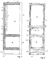
Fig. 1 einen schematischen Schnitt durch ein Kühlgerät mit zwei Nutzräumen, -
Fig. 2 eine Ansicht eines Kühlgeräts von hinten, wobei die äussere Rückwand sowie die thermische Isolation nicht dargestellt sind, -
Fig. 3 das Gerät nachFig. 2 , wobei das Vakuum-Isolationspanel dargestellt ist, -
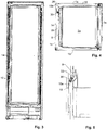
Fig. 4 einen Schnitt entlang Linie IV-IV vonFig. 2 , -
Fig. 5 einen vertikalen Schnitt senkrecht zur Rückwand im Bereich des Auffangbehälters, -
Fig. 6 einen Schnitt durch den Adapter, den Stutzen des Auffangbehälters sowie die Abflussleitung,Fig. 7 eine Ansicht des Adapters und -
Fig. 8 einen Schnitt durch den Adapter. - Die Begriffe "hinten", "Rückseite", "vorne", "Vorderseite" sind so definiert, dass sich die Türe des Kühlgeräts vorne, d.h. auf der Vorderseite befindet, während die hinten am Gerät angeordnete Rückseite die der Türe gegenüber liegende Geräteseite bezeichnet.
- Begriffe wie "oben", "unten", "horizontal" und "vertikal" beziehen sich auf die bestimmungsgemässe Orientierung des Geräts, bei welcher die Türe vertikal verläuft.
- Begriffe wie "innen", "innenseitig", "aussen", "aussenseitig" beziehen sich auf den Nutzraum des Geräts, welcher als das Innere betrachtet wird. Bei einem Bauteil bezeichnet somit "innen" die der Mitte des Nutzraums zugewandte Seite und "aussen" die von der Mitte des Nutzraums abgewandte Seite.
- Ein "Isolationsmaterial" ist ein Körper mit einer Wärmeleitfähigkeit von weniger als 0.1 W/mK, insbesondere von weniger als 0.05 W/mK. Beim Vakuum-Isolationspanelen kann der Wert sogar unter 0.01 W/mK liegen, z.B. bei 0.003 - 0.006 W/mK.
-
Fig. 1 zeigt ein Kühlgerät mit einem Gehäuse 1, in dem zwei Nutzräume 2a, 2b angeordnet sind. Jeder Nutzraum 2a, 2b ist von der Gerätevorderseite her über eine Türe 3a bzw. 3b zugänglich. - Zum Kühlen der Nutzräume 2a, 2b sind geeignete Kühlelemente 4 vorgesehen. Dabei handelt es sich z.B. um Verdampfer eines Wärmepumpenkreislaufs.
- Bevorzugt ist der erste Nutzraum 2a als Kühlfach mit einem Temperaturbereich von z.B. 0°C bis 10°C und der zweite Nutzraum 2b als Tiefkühlfach mit einem Temperaturbereich von z.B. -25°C bis -10°C ausgestaltet.
- Die Kühlelemente 4 sind jeweils bevorzugt an der Rückseite des ihnen zugeordneten Nutzraums 2a, 2b angeordnet. Die Kühlelemente 4 können jedoch auch an einer Seitenwand und/oder an der Decke des jeweiligen Nutzraums 2a, 2b angeordnet sein.
- Wie im Beispiel und nicht einschränkend für den ersten Kühlraum 2a dargestellt, kann vor dem Kühlelement 4 ein Rückwandelement 5 vorgesehen sein und einen Kühlluftkanal 6 bilden, durch welchen zu kühlende Luft vom Nutzraum 2a am Kühlelement 4 vorbei streicht.
- Optional kann ein Ventilator vorgesehen sein, um die Luft durch den Kühlluftkanal 6 zu fördern.
- Beim Kühlen kann aus der Luft Wasser auskondensieren, das sich an der vom Kühlelement 4 gekühlten Fläche niederschlägt. Deshalb ist unterhalb des Kühlelements 4 rückseitig im Nutzraum ein Auffangbehälter 8 vorgesehen.
- Vom Auffangbehälter 8 führt eine gestrichelt dargestellte Abflussleitung 10 in den Bodenbereich 12 des Kühlgeräts und dort zu einem Verdunstungsbehälter 22. Dieser steht mit der Umgebung in Kontakt, so dass das dort aufgefangene Wasser verdunsten kann.
- Die Nutzräume 2a, 2b sind nach aussen thermisch isoliert. Hierzu sind zum einen Vakuum-Isolationspanele 14 (und allenfalls 16) und zum anderen mit Isolationsmaterial ausgeschäumte Isolationsbereiche 18 vorgesehen. In der Ausführung nach
Fig. 1 ist ein Vakuum-Isolationspanel 14 an der Geräterückseite und ein weiteres Vakuum-Isolationspanel 16 an der Geräteoberseite dargestellt. Weitere solche Panele können z.B. in den Türen 3a, 3b, den Seitenwänden des Geräts sowie unterhalb einer oder beider Nutzräume 2a, 2b angeordnet werden. -
Fig. 2 - 4 zeigen den Aufbau der Rückwandisolierung. - Wie ersichtlich, ist ein einziges Vakuum-Isolationspanel 14 für die Rückwand vorgesehen. Es überdeckt mindestens 80%, insbesondere mindestens 90% beider Innenräume 2a, 2b.
- Insbesondere dank der weiter unten beschriebenen Führung der Abflussleitung 10 kann es ohne Durchbrüche ausgestaltet sein.
- Der Zwischenraum zwischen dem Vakuum-Isolationspanel 14 und der Rückwand der Nutzräume bildet Teil des erwähnten Isolationsbereichs 18 und kann (dort, wo sich keine weiteren Komponenten befinden) mit einem Isolationsmaterial ausgeschäumt sein.
- Um das Wasser vom Auffangbehälter 8 abzuführen, ist die erwähnte Abflussleitung 10 vorgesehen.
- Der Verlauf der Abflussleitung ist in
Fig. 2 bis 4 dargestellt. - Die Abflussleitung 10 besitzt einen ersten Abschnitt 10a, der mit dem Auffangbehälter 8 verbunden ist. Er führt vom Abflussbehälter 8 schräg nach aussen.
- Weiter besitzt die Abflussleitung 10 einen zweiten Abschnitt 10b, der sich an den ersten Abschnitt 10a anschliesst. Dieser verläuft in einer Ecke 20 des Kühlgeräts. Unter "Ecke" ist dabei ein Bereich zu verstehen, bei welchem zwei vertikale Wände des Geräts aufeinander treffen, im vorliegenden Fall eine Seitenwand 1a sowie die Rückwand 1c.
- Weiter kann die Abflussleitung 10 einen dritten Abschnitt 10c besitzen, der an den zweiten Abschnitt 10b anschliesst und zum Verdunstungsbehälter 22 im Bodenbereich 12 des Kühlgeräts führt.
- Der erste Abschnitt 10a hat die Aufgabe, das Wasser im Bereich des ersten Nutzraums 2a nach aussen zu führen, in die Ecke 20 des Geräts. Er verläuft mit Vorteil vollständig auf einer Höhe oberhalb des zweiten Kühlbereichs 2b, um ein Gefrieren von Wasser in diesem Abschnitt zu verhindern.
- Im Bereich des zweiten Abschnitts 10b verläuft die Abflussleitung 10 über die Höhe des zweiten Nutzraums 2b neben dem Vakuum-Isolationspanel 14 nach unten. Da sie an dieser Stelle nicht zwischen dem Vakuum-Isolationspanel 14 und dem zweiten Nutzraum 2b verläuft, sondern (von der Rückseite gesehen) seitlich des Isolationspanels 14, kann das Gefrieren von Wasser in der Leitung verhindert werden.
- Wie aus
Fig. 4 ersichtlich, kann die Abflussleitung 10 zumindest im zweiten Abschnitt 10b die Aussenwände 1a und/oder 1c berühren, die im Bereich der Ecke 20 zusammenlaufen, so dass seine Temperatur hoch bleibt. - Die angrenzenden Vakuum-Isolationspanele 14 der Rückwand 1c und 15 der Seitenwand 1b dämmen den zweiten Abschnitt 10b nach aussen nicht ab.
- Mit Vorteil verläuft die Abflussleitung 10 über mindestens 40%, insbesondere mindestens 60%, insbesondere mindestens 80%, des ersten und/oder den zweiten Abschnitt 10a, 10b gestreckt, d.h. grade.
- Die Abflussleitung 10 kann im Isolationsbereich 18 im Isolationsmaterial mindestens teilweise eingeschäumt oder in anderer Weise zumindest von einer Seite eingebettet sein. Sie sollte deshalb eine entsprechende Temperaturbeständigkeit und Dichtigkeit besitzen.
- Beispielsweise besteht die Abflussleitung 10 aus einem Rohr aus Polyethylen oder Hart-PVC.
- Wie aus
Fig. 2 ersichtlich, ist die Abflussleitung 10 an einer Stelle 26 mit dem Auffangbehälter 8 verbunden, die sich nicht in der Mittelebene des Geräts befindet, sondern näher bei einer der beiden Seitenwände 1a, 1b des Geräts, nämlich näher an derjenigen Seitenwand 1a, entlang welcher der zweite Abschnitt 10b der Abflussleitung verläuft. Dadurch kann der Weg des Wassers verkürzt werden und die Gefahr des Einfrierens wird reduziert. - Die Abflussleitung 10 ist mit dem Auffangbehälter 8 über einen Adapter 30 verbunden. Ein möglicher Aufbau des Adapters 30 ergibt sich aus
Fig. 5 - 8 . - Der Adapter 30 ist auf der Seite des Auffangbehälters 8 an einem Stutzen 32 befestigt. Der Stutzen 32 ist am Auffangbehälter 8 angeordnet.
- Der Stutzen 32 kann insbesondere direkt am Material des Auffangbehälters 8 ausgeformt sein, oder er kann z.B. am Auffangbehälter 8 angeschweisst oder angeklebt sein.
- Auf der Seite der Abflussleitung 10 ist der Adapter 30 mit dem ersten Abschnitt 10a der Abflussleitung verbunden.
- Mit anderen Worten verbindet der Adapter 30 den Stutzen 32 mit der Abflussleitung 10.
- Der Adapter 30 kann mit dem Stutzen 32 und/oder der Abflussleitung 10 durch Stecken verbunden sein.
- Hierzu besitzt der Adapter 30, wie in
Fig. 8 gezeigt, z.B. einen ersten Abschnitt 34a und einen zweiten Abschnitt 34b, die über einen dritten Abschnitt 34c miteinander verbunden sind. - Der erste und der zweite Abschnitt 34a, 34b weisen jeweils einen zylindrischen Innenbereich 36a bzw. 36b auf, deren Durchmesser auf die Abflussleitung 10 bzw. den Stutzen 32 abgestimmt sind.
- Die Abflussleitung 10 ist mit dem ersten Abschnitt verbunden, insbesondere am ersten Abschnitt 34a eingesteckt. Der Stutzen 32 ist mit dem zweiten Abschnitt 34b verbunden, insbesondere am zweiten Abschnitt 34b eingesteckt.
- Der dritte Abschnitt 34c kann typischerweise flexibler als der erste und der zweite Abschnitt ausgestaltet sein und erlaubt es, Bewegungen der Abflussleitung 10, z.B. während dem Ausschäumen des Isolationsbereichs 18, besser zu folgen, und die Gefahr eines Verrutschens des Schlauchs an seinem Anschluss wird reduziert.
- Um eine möglichst freie Bewegung zu ermöglichen, werden die Abflussleitung 10 und der Stutzen 32 mittels des Adapters 30 beabstandet voneinander gehalten, d.h. sie reichen nicht so weit in den dritten Abschnitt 34c des Adapters 30 hinein, dass sie sich berühren würden. So können die Bewegungen zwischen den beiden Teilen vom Adapter 30 gut aufgenommen werden.
- Mit Vorteil besteht der Adapter 30 aus einem thermoplastischen Material, z.B. aus TPE.
- Zumindest ist es von Vorteil, wenn der Adapter 30 aus einem weicheren und/oder elastischeren Material besteht als die Abflussleitung 10 und/oder der Stutzen 32, damit er die Bewegungen der Abflussleitung 10 besser aufnehmen kann. Dabei nimmt der Adapter 30 die Bewegung insbesondere im Abschnitt 34c auf.
- Wie ersichtlich, führt die Abflussleitung mit Vorteil am Vakuum-Isolationspanel vorbei. Sie führt also nicht durch das Vakuum-Isolationspanel hindurch, wodurch die Herstellung des Panels vereinfacht wird.
- Die vorliegende Technik kann grundsätzlich auch bei Geräten mit nur einem Nutzraum oder mit mehr als zwei Nutzräumen eingesetzt werden.
- Während in der vorliegenden Anmeldung bevorzugte Ausführungen der Erfindung beschrieben sind, ist klar darauf hinzuweisen, dass die Erfindung nicht auf diese beschränkt ist und in auch anderer Weise innerhalb des Umfangs der folgenden Ansprüche ausgeführt werden kann.
Claims (15)
- Kühlgerät mit
einem ersten Nutzraum (2a),
einem an einer Wand des ersten Nutzraums (2a) angeordneten Kühlelement (4) zum Kühlen des ersten Nutzraums (2a),
dadurch gekennzeichnet, dass ausserhalb des Kühlelements (4) und dem ersten Nutzraum (2a) ein Vakuum-Isolationspanel (14) angeordnet ist, welches mindestens 50%, insbesondere mindestens 60%, insbesondere mindestens 80% des ersten Nutzraums (2a) überdeckt. - Kühlgerät nach Anspruch 1, wobei das Vakuum-Isolationspanel (14) mindestens 90% des ersten Nutzraums (2a) überdeckt, insbesondere den ganzen ersten Nutzraum (2a).
- Kühlgerät nach einem der vorangehenden Ansprüche mit
einem Auffangbehälter (8), um beim Kühlelement (4) auskondensierende Flüssigkeit aufzufangen, und
einer Abflussleitung (10), welche vom Auffangbehälter (8) in einen Aussenbereich des Kühlgeräts führt, und insbesondere wobei der Aussenbereich sich im Bodenbereich (12) des Kühlgeräts befindet. - Kühlgerät nach Anspruch 3, wobei die Abflussleitung (10) aufweist:einen ersten Abschnitt (10a), der mit dem Auffangbehälter (8) verbunden ist,einen zweiten Abschnitt (10b), der an den ersten Abschnitt (10a) anschliesst und, von einer Rückseite des Kühlgeräts gesehen, neben dem Vakuum-Isolationspanel (14) nach unten verläuft,und insbesondere wobei der zweite Abschnitt in einer Ecke (20) des Kühlgeräts verläuft.
- Kühlgerät nach einem der Ansprüche 3 oder 4, wobei die Abflussleitung (10) zu einem Verdunstungsbehälter (22) führt, der tiefer als der erste Nutzraum (2a) angeordnet ist, und insbesondere wobei der Verdunstungsbehälter (22) mindestens teilweise vertikal unterhalb des ersten Nutzraums (2a) angeordnet ist.
- Kühlgerät nach einem der Ansprüche 3 bis 5, wobei zwischen dem Vakuum-Isolationspanel (14) und dem ersten Nutzraum (2a) ein mit einem Isolationsmaterial ausgeschäumter Isolationsbereich (18) angeordnet ist, wobei die Abflussleitung (10) mindestens teilweise im Isolationsmaterial eingeschäumt ist.
- Kühlgerät nach einem der Ansprüche 3 bis 6, wobei die Abflussleitung (10) über einen Adapter (30) mit dem Auffangbehälter (8) verbunden ist.
- Kühlgerät nach Anspruch 7, wobei der Adapter (30) aus einem weicheren Material als die Abflussleitung (10) besteht.
- Kühlgerät nach einem der Ansprüche 7 oder 8, wobei am Auffangbehälter (8) ein Stutzen (32) angeordnet ist, und wobei der Adapter (30) den Stutzen (32) mit der Abflussleitung (10) verbindet, und insbesondere wobei der Adapter (30) mit dem Stutzen und/oder der Abflussleitung (10) durch Stecken verbunden ist.
- Kühlgerät nach Anspruch 9, wobei der Adapter (30) einen ersten Abschnitt (34a), einen zweiten Abschnitt (34b) und einen dritten Abschnitt (34c) aufweist, wobei der erste und der zweite Abschnitt (34a, 34b) über den dritten Abschnitt (34c) verbunden sind,
wobei die Abflussleitung (10) mit dem ersten Abschnitt verbunden ist, insbesondere am ersten Abschnitt (34a) eingesteckt ist, und/oder wobei der Stutzen (32) mit dem zweiten Abschnitt (34b) verbunden ist, insbesondere am zweiten Abschnitt (34b) eingesteckt ist. - Kühlgerät nach einem der Ansprüche 9 oder 10, wobei der der Stutzen (32) und die Abflussleitung (10) mittels dem Adapter (30) beabstandet voneinander gehalten sind.
- Kühlgerät nach einem der vorangehenden Ansprüche mit einem zweiten Nutzraum (2b), welcher unterhalb des ersten Nutzraums (2a) angeordnet ist, und insbesondere wobei das Kühlgerät dazu ausgestaltet ist, den zweiten Nutzraum (2b) auf eine tiefere Temperatur zu kühlen als den ersten Nutzraum (2a), und insbesondere wobei die tiefere Temperatur unter dem Gefrierpunkt liegt.
- Kühlgerät nach Anspruch 12, wobei das Vakuum-Isolationspanel (14) mindestens 80% beider Nutzräume (2a, 2b) überdeckt, insbesondere 90% beider Nutzräume (2a, 2b), insbesondere beide Nutzräume (2a, 2b) vollständig.
- Kühlgerät nach einem der Ansprüche 12 oder 13 und nach einem der Ansprüche 3 bis 11, wobei die Abflussleitung (10) am zweiten Nutzraum (2b) vorbei bis unterhalb des zweiten Nutzraums (2b) führt.
- Kühlgerät nach Anspruch 14, wobei die Abflussleitung (10), von einer Rückseite des Kühlgeräts gesehen, über mindestens einen Teil der Höhe des zweiten Nutzraums (2b) neben dem Vakuum-Isolationspanel (14) nach unten verläuft.
Applications Claiming Priority (1)
| Application Number | Priority Date | Filing Date | Title |
|---|---|---|---|
| CH00682/18A CH713291A2 (de) | 2018-05-29 | 2018-05-29 | Kühlgerät mit Vakuum-Isolationspanel. |
Publications (2)
| Publication Number | Publication Date |
|---|---|
| EP3575714A1 true EP3575714A1 (de) | 2019-12-04 |
| EP3575714B1 EP3575714B1 (de) | 2025-06-25 |
Family
ID=62974851
Family Applications (1)
| Application Number | Title | Priority Date | Filing Date |
|---|---|---|---|
| EP19174357.4A Active EP3575714B1 (de) | 2018-05-29 | 2019-05-14 | Kühlgerät mit einem vakuum-isolationspanel |
Country Status (3)
| Country | Link |
|---|---|
| EP (1) | EP3575714B1 (de) |
| CN (1) | CN110542261A (de) |
| CH (1) | CH713291A2 (de) |
Cited By (1)
| Publication number | Priority date | Publication date | Assignee | Title |
|---|---|---|---|---|
| EP4403854A1 (de) * | 2023-01-20 | 2024-07-24 | Liebherr-Hausgeräte Ochsenhausen GmbH | Kühl- und/oder gefriergerät |
Citations (7)
| Publication number | Priority date | Publication date | Assignee | Title |
|---|---|---|---|---|
| US5251455A (en) * | 1992-08-14 | 1993-10-12 | Whirlpool Corporation | Energy efficient insulation system for refrigerator/freezer |
| JP2004101028A (ja) * | 2002-09-06 | 2004-04-02 | Matsushita Refrig Co Ltd | 冷蔵庫 |
| EP1505359A1 (de) * | 2002-04-22 | 2005-02-09 | Matsushita Refrigeration Company | Kühlschrank |
| DE102007051333A1 (de) * | 2007-10-26 | 2009-04-30 | BSH Bosch und Siemens Hausgeräte GmbH | Kältegerätegehäuse mit Rohrdurchführung |
| WO2015165526A1 (en) * | 2014-04-30 | 2015-11-05 | Arcelik Anonim Sirketi | Improved water drainage assembly for use in a refrigeration appliance |
| DE212014000174U1 (de) * | 2013-08-23 | 2016-04-22 | Panasonic Intellectual Property Management Co., Ltd. | Kühlschrank |
| CH711097A2 (de) * | 2016-09-21 | 2016-11-30 | V Zug Ag | Kühlgerät sowie Tauwasserleitung für ein derartiges Kühlgerät. |
Family Cites Families (9)
| Publication number | Priority date | Publication date | Assignee | Title |
|---|---|---|---|---|
| JP3679934B2 (ja) * | 1998-09-30 | 2005-08-03 | 株式会社東芝 | 冷蔵庫におけるホースの固定構造 |
| JP4576195B2 (ja) * | 2004-10-12 | 2010-11-04 | 日立アプライアンス株式会社 | 真空断熱材、及び真空断熱材を用いた冷蔵庫、並びに真空断熱材の製造方法。 |
| US7047998B2 (en) * | 2004-10-12 | 2006-05-23 | Mckee David | Gravity flow drain extension for a condensation drain line |
| CN101839605A (zh) * | 2010-06-22 | 2010-09-22 | 合肥美的荣事达电冰箱有限公司 | 冰箱及其控制方法 |
| CN102121773A (zh) * | 2011-03-30 | 2011-07-13 | 合肥美的荣事达电冰箱有限公司 | 制冷系统和具有该制冷系统的冰箱 |
| CN103277622A (zh) * | 2013-05-31 | 2013-09-04 | 武科金 | 一种用于水管快速pp接头 |
| CN204226935U (zh) * | 2014-09-23 | 2015-03-25 | 淳安中顺机械科技有限公司 | 一种塑料管件转接头 |
| CN107192196A (zh) * | 2017-06-27 | 2017-09-22 | 青岛海尔股份有限公司 | 冰箱 |
| CN207094028U (zh) * | 2017-08-21 | 2018-03-13 | 吉林喜丰节水科技股份有限公司 | 一种用于地下塑料排水管道的抗压耐腐蚀柔性接头 |
-
2018
- 2018-05-29 CH CH00682/18A patent/CH713291A2/de unknown
-
2019
- 2019-05-14 EP EP19174357.4A patent/EP3575714B1/de active Active
- 2019-05-29 CN CN201910453897.6A patent/CN110542261A/zh active Pending
Patent Citations (7)
| Publication number | Priority date | Publication date | Assignee | Title |
|---|---|---|---|---|
| US5251455A (en) * | 1992-08-14 | 1993-10-12 | Whirlpool Corporation | Energy efficient insulation system for refrigerator/freezer |
| EP1505359A1 (de) * | 2002-04-22 | 2005-02-09 | Matsushita Refrigeration Company | Kühlschrank |
| JP2004101028A (ja) * | 2002-09-06 | 2004-04-02 | Matsushita Refrig Co Ltd | 冷蔵庫 |
| DE102007051333A1 (de) * | 2007-10-26 | 2009-04-30 | BSH Bosch und Siemens Hausgeräte GmbH | Kältegerätegehäuse mit Rohrdurchführung |
| DE212014000174U1 (de) * | 2013-08-23 | 2016-04-22 | Panasonic Intellectual Property Management Co., Ltd. | Kühlschrank |
| WO2015165526A1 (en) * | 2014-04-30 | 2015-11-05 | Arcelik Anonim Sirketi | Improved water drainage assembly for use in a refrigeration appliance |
| CH711097A2 (de) * | 2016-09-21 | 2016-11-30 | V Zug Ag | Kühlgerät sowie Tauwasserleitung für ein derartiges Kühlgerät. |
Cited By (1)
| Publication number | Priority date | Publication date | Assignee | Title |
|---|---|---|---|---|
| EP4403854A1 (de) * | 2023-01-20 | 2024-07-24 | Liebherr-Hausgeräte Ochsenhausen GmbH | Kühl- und/oder gefriergerät |
Also Published As
| Publication number | Publication date |
|---|---|
| CH713291A2 (de) | 2018-07-31 |
| EP3575714B1 (de) | 2025-06-25 |
| CN110542261A (zh) | 2019-12-06 |
Similar Documents
| Publication | Publication Date | Title |
|---|---|---|
| EP3262357A1 (de) | Kältegerät | |
| WO2015128164A1 (de) | Kältegerät | |
| EP3155332B1 (de) | Kühl- und/oder gefriergerät | |
| DE102019202649A1 (de) | Kältegerät | |
| EP2522937A2 (de) | Verdunstungsvorrichtung für ein Einbaukältegerät sowie Einbaukältegerät und Verfahren zum Einbau eines Einbaukältegeräts | |
| EP3575714B1 (de) | Kühlgerät mit einem vakuum-isolationspanel | |
| EP3230664A1 (de) | No-frost-kältegerät | |
| DE102017213972A1 (de) | Kältegerät mit Verdunstungsschale | |
| EP0010181B1 (de) | Absorptionskühlmöbel | |
| CH703730A2 (de) | Haushalts-Kühlgerät mit Wärmepumpe und Peltier-Element. | |
| DE102012018021A1 (de) | Kühl- und/oder Gefriergerät | |
| CH713485A2 (de) | Kühlgerät mit aktiv gekühltem Maschinenraum. | |
| DE3314069A1 (de) | Kuehlaggregat fuer ein geschlossenes geraet, insbesondere fuer einen schaltschrank | |
| EP1132697A2 (de) | Vorrichtung zum Verdunsten von Wasser | |
| DE102010003088A1 (de) | Kältegerät mit Tauwasserverdunster | |
| WO2011020801A1 (de) | Kältegerät mit einem abtauwasserkanal und einem siphon | |
| DE827066C (de) | Kuehlschrank | |
| CH711097B1 (de) | Kühlgerät sowie Tauwasserleitung für ein derartiges Kühlgerät. | |
| WO2016078894A1 (de) | Kältegerät mit einem kaltluftkanal | |
| DE102015006559A1 (de) | Wärmeisoliertes Behältnis | |
| DE102017114588A1 (de) | Kühl- und/oder Gefriergerät | |
| DE102010054450A1 (de) | Kühl- und/oder Gefriergerät | |
| DE102011004107A1 (de) | Haushaltskältegerät mit ungeregelten Expansionsventilen | |
| DE102009002801A1 (de) | Kältegerät, insbesondere Haushaltskältegerät mit einer Tauwasserrinne | |
| DE102022127841A1 (de) | Kühl- und/oder Gefriergerät |
Legal Events
| Date | Code | Title | Description |
|---|---|---|---|
| PUAI | Public reference made under article 153(3) epc to a published international application that has entered the european phase |
Free format text: ORIGINAL CODE: 0009012 |
|
| STAA | Information on the status of an ep patent application or granted ep patent |
Free format text: STATUS: THE APPLICATION HAS BEEN PUBLISHED |
|
| AK | Designated contracting states |
Kind code of ref document: A1 Designated state(s): AL AT BE BG CH CY CZ DE DK EE ES FI FR GB GR HR HU IE IS IT LI LT LU LV MC MK MT NL NO PL PT RO RS SE SI SK SM TR |
|
| AX | Request for extension of the european patent |
Extension state: BA ME |
|
| STAA | Information on the status of an ep patent application or granted ep patent |
Free format text: STATUS: REQUEST FOR EXAMINATION WAS MADE |
|
| 17P | Request for examination filed |
Effective date: 20200604 |
|
| RBV | Designated contracting states (corrected) |
Designated state(s): AL AT BE BG CH CY CZ DE DK EE ES FI FR GB GR HR HU IE IS IT LI LT LU LV MC MK MT NL NO PL PT RO RS SE SI SK SM TR |
|
| STAA | Information on the status of an ep patent application or granted ep patent |
Free format text: STATUS: EXAMINATION IS IN PROGRESS |
|
| 17Q | First examination report despatched |
Effective date: 20210503 |
|
| GRAP | Despatch of communication of intention to grant a patent |
Free format text: ORIGINAL CODE: EPIDOSNIGR1 |
|
| STAA | Information on the status of an ep patent application or granted ep patent |
Free format text: STATUS: GRANT OF PATENT IS INTENDED |
|
| INTG | Intention to grant announced |
Effective date: 20250314 |
|
| GRAS | Grant fee paid |
Free format text: ORIGINAL CODE: EPIDOSNIGR3 |
|
| GRAA | (expected) grant |
Free format text: ORIGINAL CODE: 0009210 |
|
| STAA | Information on the status of an ep patent application or granted ep patent |
Free format text: STATUS: THE PATENT HAS BEEN GRANTED |
|
| P01 | Opt-out of the competence of the unified patent court (upc) registered |
Free format text: CASE NUMBER: APP_20259/2025 Effective date: 20250429 |
|
| AK | Designated contracting states |
Kind code of ref document: B1 Designated state(s): AL AT BE BG CH CY CZ DE DK EE ES FI FR GB GR HR HU IE IS IT LI LT LU LV MC MK MT NL NO PL PT RO RS SE SI SK SM TR |
|
| REG | Reference to a national code |
Ref country code: GB Ref legal event code: FG4D Free format text: NOT ENGLISH |
|
| REG | Reference to a national code |
Ref country code: CH Ref legal event code: EP |
|
| REG | Reference to a national code |
Ref country code: CH Ref legal event code: EP |
|
| REG | Reference to a national code |
Ref country code: IE Ref legal event code: FG4D Free format text: LANGUAGE OF EP DOCUMENT: GERMAN |
|
| REG | Reference to a national code |
Ref country code: DE Ref legal event code: R096 Ref document number: 502019013496 Country of ref document: DE |
|
| PG25 | Lapsed in a contracting state [announced via postgrant information from national office to epo] |
Ref country code: FI Free format text: LAPSE BECAUSE OF FAILURE TO SUBMIT A TRANSLATION OF THE DESCRIPTION OR TO PAY THE FEE WITHIN THE PRESCRIBED TIME-LIMIT Effective date: 20250625 |
|
| REG | Reference to a national code |
Ref country code: LT Ref legal event code: MG9D |
|
| PG25 | Lapsed in a contracting state [announced via postgrant information from national office to epo] |
Ref country code: NO Free format text: LAPSE BECAUSE OF FAILURE TO SUBMIT A TRANSLATION OF THE DESCRIPTION OR TO PAY THE FEE WITHIN THE PRESCRIBED TIME-LIMIT Effective date: 20250925 Ref country code: GR Free format text: LAPSE BECAUSE OF FAILURE TO SUBMIT A TRANSLATION OF THE DESCRIPTION OR TO PAY THE FEE WITHIN THE PRESCRIBED TIME-LIMIT Effective date: 20250926 |
|
| PG25 | Lapsed in a contracting state [announced via postgrant information from national office to epo] |
Ref country code: BG Free format text: LAPSE BECAUSE OF FAILURE TO SUBMIT A TRANSLATION OF THE DESCRIPTION OR TO PAY THE FEE WITHIN THE PRESCRIBED TIME-LIMIT Effective date: 20250625 |
|
| PG25 | Lapsed in a contracting state [announced via postgrant information from national office to epo] |
Ref country code: HR Free format text: LAPSE BECAUSE OF FAILURE TO SUBMIT A TRANSLATION OF THE DESCRIPTION OR TO PAY THE FEE WITHIN THE PRESCRIBED TIME-LIMIT Effective date: 20250625 |
|
| PG25 | Lapsed in a contracting state [announced via postgrant information from national office to epo] |
Ref country code: RS Free format text: LAPSE BECAUSE OF FAILURE TO SUBMIT A TRANSLATION OF THE DESCRIPTION OR TO PAY THE FEE WITHIN THE PRESCRIBED TIME-LIMIT Effective date: 20250925 |
|
| PG25 | Lapsed in a contracting state [announced via postgrant information from national office to epo] |
Ref country code: LV Free format text: LAPSE BECAUSE OF FAILURE TO SUBMIT A TRANSLATION OF THE DESCRIPTION OR TO PAY THE FEE WITHIN THE PRESCRIBED TIME-LIMIT Effective date: 20250625 |
|
| REG | Reference to a national code |
Ref country code: NL Ref legal event code: MP Effective date: 20250625 |
|
| PG25 | Lapsed in a contracting state [announced via postgrant information from national office to epo] |
Ref country code: NL Free format text: LAPSE BECAUSE OF FAILURE TO SUBMIT A TRANSLATION OF THE DESCRIPTION OR TO PAY THE FEE WITHIN THE PRESCRIBED TIME-LIMIT Effective date: 20250625 |
|
| PG25 | Lapsed in a contracting state [announced via postgrant information from national office to epo] |
Ref country code: PT Free format text: LAPSE BECAUSE OF FAILURE TO SUBMIT A TRANSLATION OF THE DESCRIPTION OR TO PAY THE FEE WITHIN THE PRESCRIBED TIME-LIMIT Effective date: 20251027 |
|
| PG25 | Lapsed in a contracting state [announced via postgrant information from national office to epo] |
Ref country code: IS Free format text: LAPSE BECAUSE OF FAILURE TO SUBMIT A TRANSLATION OF THE DESCRIPTION OR TO PAY THE FEE WITHIN THE PRESCRIBED TIME-LIMIT Effective date: 20251025 |
|
| PG25 | Lapsed in a contracting state [announced via postgrant information from national office to epo] |
Ref country code: SM Free format text: LAPSE BECAUSE OF FAILURE TO SUBMIT A TRANSLATION OF THE DESCRIPTION OR TO PAY THE FEE WITHIN THE PRESCRIBED TIME-LIMIT Effective date: 20250625 |
|
| PG25 | Lapsed in a contracting state [announced via postgrant information from national office to epo] |
Ref country code: CZ Free format text: LAPSE BECAUSE OF FAILURE TO SUBMIT A TRANSLATION OF THE DESCRIPTION OR TO PAY THE FEE WITHIN THE PRESCRIBED TIME-LIMIT Effective date: 20250625 |
|
| PG25 | Lapsed in a contracting state [announced via postgrant information from national office to epo] |
Ref country code: PL Free format text: LAPSE BECAUSE OF FAILURE TO SUBMIT A TRANSLATION OF THE DESCRIPTION OR TO PAY THE FEE WITHIN THE PRESCRIBED TIME-LIMIT Effective date: 20250625 |
|
| PG25 | Lapsed in a contracting state [announced via postgrant information from national office to epo] |
Ref country code: EE Free format text: LAPSE BECAUSE OF FAILURE TO SUBMIT A TRANSLATION OF THE DESCRIPTION OR TO PAY THE FEE WITHIN THE PRESCRIBED TIME-LIMIT Effective date: 20250625 |
|
| PG25 | Lapsed in a contracting state [announced via postgrant information from national office to epo] |
Ref country code: SK Free format text: LAPSE BECAUSE OF FAILURE TO SUBMIT A TRANSLATION OF THE DESCRIPTION OR TO PAY THE FEE WITHIN THE PRESCRIBED TIME-LIMIT Effective date: 20250625 |
|
| PG25 | Lapsed in a contracting state [announced via postgrant information from national office to epo] |
Ref country code: ES Free format text: LAPSE BECAUSE OF FAILURE TO SUBMIT A TRANSLATION OF THE DESCRIPTION OR TO PAY THE FEE WITHIN THE PRESCRIBED TIME-LIMIT Effective date: 20250625 |
|
| PG25 | Lapsed in a contracting state [announced via postgrant information from national office to epo] |
Ref country code: DK Free format text: LAPSE BECAUSE OF FAILURE TO SUBMIT A TRANSLATION OF THE DESCRIPTION OR TO PAY THE FEE WITHIN THE PRESCRIBED TIME-LIMIT Effective date: 20250625 |
|
| PLBE | No opposition filed within time limit |
Free format text: ORIGINAL CODE: 0009261 |
|
| STAA | Information on the status of an ep patent application or granted ep patent |
Free format text: STATUS: NO OPPOSITION FILED WITHIN TIME LIMIT |
|
| REG | Reference to a national code |
Ref country code: CH Ref legal event code: L10 Free format text: ST27 STATUS EVENT CODE: U-0-0-L10-L00 (AS PROVIDED BY THE NATIONAL OFFICE) Effective date: 20260507 |