EP3575711A1 - Refrigeration cycle device - Google Patents
Refrigeration cycle device Download PDFInfo
- Publication number
- EP3575711A1 EP3575711A1 EP17894265.2A EP17894265A EP3575711A1 EP 3575711 A1 EP3575711 A1 EP 3575711A1 EP 17894265 A EP17894265 A EP 17894265A EP 3575711 A1 EP3575711 A1 EP 3575711A1
- Authority
- EP
- European Patent Office
- Prior art keywords
- compressor
- passage
- control device
- refrigerant
- refrigeration cycle
- Prior art date
- Legal status (The legal status is an assumption and is not a legal conclusion. Google has not performed a legal analysis and makes no representation as to the accuracy of the status listed.)
- Withdrawn
Links
Images






Classifications
-
- F—MECHANICAL ENGINEERING; LIGHTING; HEATING; WEAPONS; BLASTING
- F25—REFRIGERATION OR COOLING; COMBINED HEATING AND REFRIGERATION SYSTEMS; HEAT PUMP SYSTEMS; MANUFACTURE OR STORAGE OF ICE; LIQUEFACTION SOLIDIFICATION OF GASES
- F25B—REFRIGERATION MACHINES, PLANTS OR SYSTEMS; COMBINED HEATING AND REFRIGERATION SYSTEMS; HEAT PUMP SYSTEMS
- F25B1/00—Compression machines, plants or systems with non-reversible cycle
- F25B1/10—Compression machines, plants or systems with non-reversible cycle with multi-stage compression
-
- F—MECHANICAL ENGINEERING; LIGHTING; HEATING; WEAPONS; BLASTING
- F25—REFRIGERATION OR COOLING; COMBINED HEATING AND REFRIGERATION SYSTEMS; HEAT PUMP SYSTEMS; MANUFACTURE OR STORAGE OF ICE; LIQUEFACTION SOLIDIFICATION OF GASES
- F25B—REFRIGERATION MACHINES, PLANTS OR SYSTEMS; COMBINED HEATING AND REFRIGERATION SYSTEMS; HEAT PUMP SYSTEMS
- F25B49/00—Arrangement or mounting of control or safety devices
- F25B49/02—Arrangement or mounting of control or safety devices for compression type machines, plants or systems
-
- F—MECHANICAL ENGINEERING; LIGHTING; HEATING; WEAPONS; BLASTING
- F25—REFRIGERATION OR COOLING; COMBINED HEATING AND REFRIGERATION SYSTEMS; HEAT PUMP SYSTEMS; MANUFACTURE OR STORAGE OF ICE; LIQUEFACTION SOLIDIFICATION OF GASES
- F25B—REFRIGERATION MACHINES, PLANTS OR SYSTEMS; COMBINED HEATING AND REFRIGERATION SYSTEMS; HEAT PUMP SYSTEMS
- F25B1/00—Compression machines, plants or systems with non-reversible cycle
- F25B1/04—Compression machines, plants or systems with non-reversible cycle with compressor of rotary type
-
- F—MECHANICAL ENGINEERING; LIGHTING; HEATING; WEAPONS; BLASTING
- F25—REFRIGERATION OR COOLING; COMBINED HEATING AND REFRIGERATION SYSTEMS; HEAT PUMP SYSTEMS; MANUFACTURE OR STORAGE OF ICE; LIQUEFACTION SOLIDIFICATION OF GASES
- F25B—REFRIGERATION MACHINES, PLANTS OR SYSTEMS; COMBINED HEATING AND REFRIGERATION SYSTEMS; HEAT PUMP SYSTEMS
- F25B2400/00—Component parts or details not otherwise provided for in this subclass
- F25B2400/04—Refrigeration circuit bypassing means
- F25B2400/0401—Refrigeration circuit bypassing means for compressors
-
- F—MECHANICAL ENGINEERING; LIGHTING; HEATING; WEAPONS; BLASTING
- F25—REFRIGERATION OR COOLING; COMBINED HEATING AND REFRIGERATION SYSTEMS; HEAT PUMP SYSTEMS; MANUFACTURE OR STORAGE OF ICE; LIQUEFACTION SOLIDIFICATION OF GASES
- F25B—REFRIGERATION MACHINES, PLANTS OR SYSTEMS; COMBINED HEATING AND REFRIGERATION SYSTEMS; HEAT PUMP SYSTEMS
- F25B2400/00—Component parts or details not otherwise provided for in this subclass
- F25B2400/07—Details of compressors or related parts
- F25B2400/075—Details of compressors or related parts with parallel compressors
-
- F—MECHANICAL ENGINEERING; LIGHTING; HEATING; WEAPONS; BLASTING
- F25—REFRIGERATION OR COOLING; COMBINED HEATING AND REFRIGERATION SYSTEMS; HEAT PUMP SYSTEMS; MANUFACTURE OR STORAGE OF ICE; LIQUEFACTION SOLIDIFICATION OF GASES
- F25B—REFRIGERATION MACHINES, PLANTS OR SYSTEMS; COMBINED HEATING AND REFRIGERATION SYSTEMS; HEAT PUMP SYSTEMS
- F25B2400/00—Component parts or details not otherwise provided for in this subclass
- F25B2400/13—Economisers
-
- F—MECHANICAL ENGINEERING; LIGHTING; HEATING; WEAPONS; BLASTING
- F25—REFRIGERATION OR COOLING; COMBINED HEATING AND REFRIGERATION SYSTEMS; HEAT PUMP SYSTEMS; MANUFACTURE OR STORAGE OF ICE; LIQUEFACTION SOLIDIFICATION OF GASES
- F25B—REFRIGERATION MACHINES, PLANTS OR SYSTEMS; COMBINED HEATING AND REFRIGERATION SYSTEMS; HEAT PUMP SYSTEMS
- F25B2600/00—Control issues
- F25B2600/02—Compressor control
- F25B2600/025—Compressor control by controlling speed
- F25B2600/0251—Compressor control by controlling speed with on-off operation
-
- F—MECHANICAL ENGINEERING; LIGHTING; HEATING; WEAPONS; BLASTING
- F25—REFRIGERATION OR COOLING; COMBINED HEATING AND REFRIGERATION SYSTEMS; HEAT PUMP SYSTEMS; MANUFACTURE OR STORAGE OF ICE; LIQUEFACTION SOLIDIFICATION OF GASES
- F25B—REFRIGERATION MACHINES, PLANTS OR SYSTEMS; COMBINED HEATING AND REFRIGERATION SYSTEMS; HEAT PUMP SYSTEMS
- F25B2600/00—Control issues
- F25B2600/25—Control of valves
- F25B2600/2501—Bypass valves
-
- F—MECHANICAL ENGINEERING; LIGHTING; HEATING; WEAPONS; BLASTING
- F25—REFRIGERATION OR COOLING; COMBINED HEATING AND REFRIGERATION SYSTEMS; HEAT PUMP SYSTEMS; MANUFACTURE OR STORAGE OF ICE; LIQUEFACTION SOLIDIFICATION OF GASES
- F25B—REFRIGERATION MACHINES, PLANTS OR SYSTEMS; COMBINED HEATING AND REFRIGERATION SYSTEMS; HEAT PUMP SYSTEMS
- F25B2700/00—Sensing or detecting of parameters; Sensors therefor
- F25B2700/19—Pressures
- F25B2700/193—Pressures of the compressor
- F25B2700/1931—Discharge pressures
-
- F—MECHANICAL ENGINEERING; LIGHTING; HEATING; WEAPONS; BLASTING
- F25—REFRIGERATION OR COOLING; COMBINED HEATING AND REFRIGERATION SYSTEMS; HEAT PUMP SYSTEMS; MANUFACTURE OR STORAGE OF ICE; LIQUEFACTION SOLIDIFICATION OF GASES
- F25B—REFRIGERATION MACHINES, PLANTS OR SYSTEMS; COMBINED HEATING AND REFRIGERATION SYSTEMS; HEAT PUMP SYSTEMS
- F25B2700/00—Sensing or detecting of parameters; Sensors therefor
- F25B2700/19—Pressures
- F25B2700/193—Pressures of the compressor
- F25B2700/1933—Suction pressures
-
- F—MECHANICAL ENGINEERING; LIGHTING; HEATING; WEAPONS; BLASTING
- F25—REFRIGERATION OR COOLING; COMBINED HEATING AND REFRIGERATION SYSTEMS; HEAT PUMP SYSTEMS; MANUFACTURE OR STORAGE OF ICE; LIQUEFACTION SOLIDIFICATION OF GASES
- F25B—REFRIGERATION MACHINES, PLANTS OR SYSTEMS; COMBINED HEATING AND REFRIGERATION SYSTEMS; HEAT PUMP SYSTEMS
- F25B2700/00—Sensing or detecting of parameters; Sensors therefor
- F25B2700/21—Temperatures
- F25B2700/2104—Temperatures of an indoor room or compartment
-
- F—MECHANICAL ENGINEERING; LIGHTING; HEATING; WEAPONS; BLASTING
- F25—REFRIGERATION OR COOLING; COMBINED HEATING AND REFRIGERATION SYSTEMS; HEAT PUMP SYSTEMS; MANUFACTURE OR STORAGE OF ICE; LIQUEFACTION SOLIDIFICATION OF GASES
- F25B—REFRIGERATION MACHINES, PLANTS OR SYSTEMS; COMBINED HEATING AND REFRIGERATION SYSTEMS; HEAT PUMP SYSTEMS
- F25B2700/00—Sensing or detecting of parameters; Sensors therefor
- F25B2700/21—Temperatures
- F25B2700/2106—Temperatures of fresh outdoor air
-
- F—MECHANICAL ENGINEERING; LIGHTING; HEATING; WEAPONS; BLASTING
- F25—REFRIGERATION OR COOLING; COMBINED HEATING AND REFRIGERATION SYSTEMS; HEAT PUMP SYSTEMS; MANUFACTURE OR STORAGE OF ICE; LIQUEFACTION SOLIDIFICATION OF GASES
- F25B—REFRIGERATION MACHINES, PLANTS OR SYSTEMS; COMBINED HEATING AND REFRIGERATION SYSTEMS; HEAT PUMP SYSTEMS
- F25B41/00—Fluid-circulation arrangements
- F25B41/40—Fluid line arrangements
- F25B41/42—Arrangements for diverging or converging flows, e.g. branch lines or junctions
Definitions
- the present disclosure relates to a refrigeration cycle device including plural compressors.
- a refrigeration cycle device which includes plural compressors to compress refrigerant.
- a refrigeration cycle device described in Patent Literature 1 includes flow passage switching means for switching a connection state between two compressors to a parallel connection state or a series connection state, the flow passage switching means including six connection ports.
- the refrigeration cycle device connects the two compressors in series by the operation of the flow passage switching means during a cooling operation and constitutes a so-called economizer refrigeration cycle using an intermediate heat exchanger.
- part of a refrigerant flowing on the downstream side of an outdoor heat exchanger is diverted, decompressed by a capillary tube, and then introduced into the intermediate heat exchanger.
- the refrigerant flowing out of the intermediate heat exchanger and a refrigerant discharged from the low-stage side compressor are mixed and flow into the high-stage side compressor. Accordingly, the refrigeration cycle device reduces an enthalpy of the refrigerant to increase a cooling capacity during the cooling operation.
- the refrigeration cycle device connects the two compressors in parallel by the operation of the flow passage switching means during a heating operation.
- the intermediate heat exchanger is used as a mere refrigerant passage.
- Patent Literature 1 JP H09-145189A
- the refrigeration cycle device described in Patent Literature 1 has a complicated structure in which the flow passage switching means switches flow passages connected to the six connection ports. Further, in the refrigeration cycle device, piping for connecting the two compressors, the flow passage switching means, and the outdoor heat exchanger has a complicated configuration.
- the intermediate heat exchanger is fully utilized only when the two compressors are connected in series and used as a mere refrigerant passage when the two compressors are connected in parallel. That is, in the refrigeration cycle device, the intermediate heat exchanger is not effectively utilized.
- the refrigeration cycle device since the refrigeration cycle device includes the first passage, the second passage, and the switching unit for switching the two passages, the refrigeration cycle device is capable of switching a connection state between the first compressor and the second compressor to a series connection state or a parallel connection state.
- the refrigeration cycle device makes it possible to simplify the configuration of the switching unit and the configuration of piping for switching the connection state between the plurality of compressors to a series connection state or a parallel connection state.
- the intermediate heat exchanger exchanges heat between the refrigerant flowing through the third passage on the downstream side relative to the first expansion valve and the refrigerant flowing through the fourth passage on the upstream side relative to the second expansion valve in any of the series connection state and the parallel connection state between the compressors.
- a subcooling degree of the refrigerant flowing through the fourth passage on the downstream side of the intermediate heat exchanger increases.
- the refrigeration cycle device is capable of increasing the cooling capability for cooling air in the space to be cooled by effectively utilizing the intermediate heat exchanger in any of the series connection state and the parallel connection state between the compressors.
- a refrigeration cycle device of the first embodiment is used in a refrigerator which cools air in a freezer as a space to be cooled and has a function of cooling an in-storage temperature of the freezer to a very low temperature, for example, approximately -30°C to -10°C.
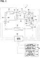
- the refrigeration cycle device 1 includes a first compressor 11, a second compressor 12, a switching unit 13, a condenser 14, a first expansion valve 15, an intermediate heat exchanger 16, a second expansion valve 17, and an evaporator 18 which are connected through, for example, pipes.
- a fluorocarbon refrigerant such as R404A can be employed as a refrigerant circulating through the refrigeration cycle device 1.
- Each component of the refrigeration cycle device 1 is driven and controlled by a control device 20.
- a signal line between the control device 20 and each component is indicated by a broken line.
- the first compressor 11 and the second compressor 12 are both electric compressors.
- Each of the first compressor 11 and the second compressor 12 includes a refrigerant compression mechanism (not illustrated) and an electric motor (not illustrated) for rotating the refrigerant compression mechanism.
- the refrigerant compression mechanism is driven to rotate by the electric motor to compress the refrigerant sucked through a suction port and discharge the refrigerant through a discharge port.
- the refrigerant compression mechanism is a fixed displacement compression mechanism whose discharge capacity is fixed. For example, a rotary or scroll compression mechanism can be employed as the refrigerant compression mechanism.
- the electric motor is driven and controlled by the control device 20.
- a refrigerant discharge amount of each of the first compressor 11 and the second compressor 12 is varied by controlling a rotation speed of the electric motor by the control device 20.
- the switching unit 13 is disposed on the discharge side of the first compressor 11.
- the switching unit 13 of the present embodiment is a flow passage switching valve which includes an inflow port 130, a first outflow port 131, and a second outflow port 132.
- the switching unit 13 interrupts communication between the inflow port 130 and the second outflow port 132.
- the switching unit 13 interrupts communication between the inflow port 130 and the first outflow port 131, the switching unit 13 causes the inflow port 130 and the second outflow port 132 to communicate with each other.
- the switching unit 13 is, for example, a three-way valve.
- the inflow port 130 is connected to a passage on the discharge side of the first compressor 11.
- the first outflow port 131 is connected to a first passage 21, and the second outflow port 132 is connected to a second passage 22.
- the switching unit 13 is capable of switching the flow of the refrigerant discharged from the first compressor 11 to the first passage 21 or the second passage 22.
- the second compressor 12 is disposed on the middle of the second passage 22.
- the second compressor 12 compresses and discharges the refrigerant flowing through the second passage 22.
- a part of the second passage 22 on the discharge side of the second compressor 12, a part of the first passage 21 on the side opposite to the switching unit 13, and a passage on the inlet side of the condenser 14 are connected by a first connector 25 which is a three-way joint. Accordingly, the refrigerant flowing through the first passage 21 or the second passage 22 flows into the condenser 14 via the first connector 25.
- the first passage 21 connects the first outflow port 131 of the switching unit 13 and the first connector 25 to each other.
- the second passage 22 connects the second outflow port 132 of the switching unit 13 and the first connector 25 to each other.
- a second connector 26 which is a three-way joint is disposed between the second outflow port 132 of the switching unit 13 and a suction port of the second compressor 12.
- the second connector 26 connects the second passage 22 and a third passage 23 (described below).
- the second connector 26 connects a part of the second passage 22 on the suction side of the second compressor 12 and a part of the third passage 23 on the downstream side of the intermediate heat exchanger 16.
- the first connector 25 and the second connector 26 may include plural pipes joined together or plural flow passages formed on a metal block or a resin block.
- the condenser 14 is a radiation heat exchanger which exchanges heat between the refrigerant flowing through a refrigerant passage (not illustrated) formed inside the condenser 14 and air outside the freezer (that is, the outside air) to radiate heat of the high-pressure refrigerant to the outside air.
- the high-pressure refrigerant flowing through the refrigerant passage inside the condenser 14 is cooled and condensed by radiating heat to the outside air.
- the flow passage on the outlet side of the condenser 14 is divided into the third passage 23 and a fourth passage 24 by a branch unit 27. That is, the passage on the outlet side of the condenser 14, the third passage 23, and the fourth passage 24 are connected by the branch unit 27 which is a three-way joint. Accordingly, the refrigerant flowing out of the outlet side of the condenser 14 is divided into the third passage 23 and the fourth passage 24.
- the branch unit 27 may include plural pipes joined together or plural flow passages formed on a metal block or a resin block.
- the third passage 23 connects the branch unit 27 and the second connector 26 to each other.
- the fourth passage 24 connects the branch unit 27 and a suction port of the first compressor 11 to each other.
- the first expansion valve 15 for decompressing the refrigerant flowing through the third passage 23 is disposed on the middle of the third passage 23.
- the refrigerant decompressed by the first expansion valve 15 becomes a gas-liquid two-phase state and flows into the intermediate heat exchanger 16. That is, the first expansion valve 15 is disposed on the upstream side of the intermediate heat exchanger 16 on the third passage 23.
- the refrigerant flowing through the fourth passage 24 also flows into the intermediate heat exchanger 16.
- the second expansion valve 17 for decompressing the refrigerant flowing through the fourth passage 24 is disposed on the downstream side of the intermediate heat exchanger 16.
- the first expansion valve 15 and the second expansion valve 17 are flow control valves capable of mechanically or electrically controlling a refrigerant flow rate.
- the first expansion valve 15 changes a valve opening degree by a mechanical mechanism to control the refrigerant flow rate on the basis of the temperature and the pressure of the refrigerant on the outlet side of the intermediate heat exchanger 16.
- the second expansion valve 17 changes a valve opening degree by a mechanical mechanism to control the refrigerant flow rate on the basis of the temperature and the pressure of the refrigerant on the outlet side of the evaporator 18.
- heat is exchanged between the refrigerant flowing through the third passage 23 on the downstream side relative to the first expansion valve 15 and the refrigerant flowing through the fourth passage 24 on the upstream side relative to the second expansion valve 17. That is, in the intermediate heat exchanger 16, heat is exchanged between the refrigerant that has been decompressed by the first expansion valve 15 and brought into a gas-liquid two-phase state on the third passage 23 and the high-temperature and high-pressure refrigerant flowing through the fourth passage 24. Accordingly, a subcooling degree of the refrigerant flowing through the fourth passage 24 increases.
- the intermediate heat exchanger 16 illustrated in FIG. 1 is a counterflow heat exchanger in which a flow direction of the refrigerant flowing through the third passage 23 is opposite to a flow direction of the refrigerant flowing through the fourth passage 24.
- the refrigerant flowing through the third passage 23 and the refrigerant flowing through the fourth passage 24 exchange heat without being mixed.
- the intermediate heat exchanger 16 may be a parallel flow heat exchanger in which the flow direction of the refrigerant flowing through the third passage 23 is the same as the flow direction of the refrigerant flowing through the fourth passage 24.
- the refrigerant flowing through the third passage 23 on the downstream side of the intermediate heat exchanger 16 flows into the second passage 22 through the second connector 26.
- a check valve (not illustrated) may be disposed between the intermediate heat exchanger 16 and the second connector 26 on the third passage 23.
- the refrigerant flowing through the fourth passage 24 on the downstream side of the intermediate heat exchanger 16 is decompressed by the second expansion valve 17 and brought into a gas-liquid two-phase state, and flows into the evaporator 18.
- the evaporator 18 is disposed on the downstream side of the second expansion valve 17 on the fourth passage 24.
- heat is exchanged between the refrigerant that has been decompressed by the second expansion valve 17 and brought into a gas-liquid two-phase state on the fourth passage 24 and air circulating through the freezer as the space to be cooled. Accordingly, air in the space to be cooled is cooled.
- a part of the fourth passage 24 on the downstream side of the evaporator 18 is connected to the suction port of the first compressor 11.
- the refrigerant flowing out of the evaporator 18 toward the first compressor 11 is sucked into the suction port of the first compressor 11.
- the refrigeration cycle device 1 is provided with a plurality of pressure sensors for detecting the pressure of the refrigerant. Specifically, a first pressure sensor 31 is disposed on a part of the second passage 22 on the discharge side of the second compressor 12. The first pressure sensor 31 detects the pressure of the refrigerant discharged from the second compressor 12. The first pressure sensor 31 only needs to be disposed on a passage between the discharge side of the second compressor 12 and the second expansion valve 17.
- a second pressure sensor 32 is disposed on a part of the fourth passage 24 on the downstream side of the evaporator 18.
- the second pressure sensor 32 detects the pressure of the refrigerant decompressed by the second expansion valve 17.
- the second pressure sensor 32 only needs to be disposed on a passage between the downstream side of the second expansion valve 17 and the first compressor 11.
- a third pressure sensor 33 is disposed on a part of the third passage 23 on the downstream side of the intermediate heat exchanger 16.
- the third pressure sensor 33 detects the pressure of the refrigerant decompressed by the first expansion valve 15.
- the third pressure sensor 33 only needs to be disposed on a passage between the downstream side of the first expansion valve 15 and the second compressor 12.
- All detection signals output from the first to third pressure sensors 33 are input to the control device 20.
- the control device 20 includes a microcomputer which includes a CPU and a memory such as a ROM and a RAM, and a peripheral circuit thereof.
- the control device 20 performs various operations and processes in accordance with a control program stored in the memory to control the operation of a device to be controlled which is connected to the output side.
- the memory of the control device 20 includes a non-transitory tangible storage medium.
- a detection signal of an in-storage temperature sensor 34 which detects an air temperature Tfr in the space to be cooled and a detection signal of an outside air temperature sensor 35 which detects the temperature of the outside air which exchanges heat with the high-pressure refrigerant in the condenser 14 are input to the control device 20.
- the control device 20 is electrically connected to an operation panel 36.
- the operation panel 36 is provided with an activation/stop switch 37 which outputs a start request signal or a stop request signal for the freezer and a temperature setting switch 38 for setting a set temperature Tset which is set as a target value for cooling the air temperature in the space to be cooled.
- An operation signal of the activation/stop switch 37 and an operation signal of the temperature setting switch 38 are also input to the control device 20.
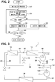
- FIG. 2 is a flowchart illustrating a control process executed by the control device 20.
- the control process is started when the activation/stop switch 37 disposed on the operation panel 36 outputs the start request signal.
- step S10 an initialization process of the control device 20 is performed.
- step S20 the control device 20 reads a detection signal of the in-storage temperature sensor 34, a detection signal of the outside air temperature sensor 35, an operation signal of the temperature setting switch 38, and the like.
- step S30 the control device 20 determines whether the difference between the air temperature Tfr in the space to be cooled and the set temperature Tset is larger than a predetermined temperature Tth.
- the predetermined temperature Tth is appropriately determined in advance by, for example, an experiment and stored in the memory of the control device 20.
- the control device 20 determines that a cool down mode which requires a large cooling capacity should be executed and shifts the process to step S40.
- step S40 the control device 20 drives the switching unit 13 so that communication between the inflow port 130 and the second outflow port 132 of the switching unit 13 is interrupted and the inflow port 130 and the first outflow port 131 communicate with each other. That is, the control device 20 drives the switching unit 13 to bring the first compressor 11 and the second compressor 12 into a parallel connection state.
- the state at this time is illustrated in FIG. 3 .
- a part of the second passage 22 where no refrigerant flows is indicated by a broken line.
- the refrigerant discharged from the first compressor 11 flows to the first passage 21 without flowing to the second passage 22.
- the second compressor 12 which is disposed on the second passage 22 compresses only the refrigerant flowing into the second compressor 12 from the third passage 23.
- the intermediate heat exchanger 16 heat is exchanged between the refrigerant flowing through the third passage 23 and the refrigerant flowing through the fourth passage 24. Accordingly, the subcooling degree of the refrigerant flowing through the fourth passage 24 on the downstream side of the intermediate heat exchanger 16 increases.
- the refrigeration cycle device 1 is capable of increasing the cooling capacity.
- step S30 when the difference between the air temperature Tfr in the space to be cooled and the set temperature Tset is smaller than the predetermined temperature Tth in step S30, the control device 20 determines that an in-range mode which requires fine capacity control rather than a large cooling capacity should be executed. Then, the control device 20 shifts the process to step S50.
- step S50 the control device 20 drives the switching unit 13 so that communication between the inflow port 130 and the first outflow port 131 of the switching unit 13 is interrupted and the inflow port 130 and the second outflow port 132 communicate with each other. That is, the control device 20 brings the first compressor 11 and the second compressor 12 into a series connection state. That sate at this time is illustrated in FIG. 4 . In FIG. 4 , a part of the first passage 21 where no refrigerant flows is indicated by a broken line.
- the refrigerant discharged from the first compressor 11 flows to the second passage 22 without flowing to the first passage 21.
- the second compressor 12 which is disposed on the second passage 22 compresses a mixture of the refrigerant discharged from the first compressor 11 and the refrigerant flowing into the second compressor 12 from the third passage 23.
- the control device 20 controls the first expansion valve 15 so that the pressure of the refrigerant on the downstream side of the first expansion valve 15 on the third passage 23 and the pressure of the refrigerant discharged from the first compressor 11 become equal to or close to each other.
- control device 20 controls the rotation speed of each of the first compressor 11 and the second compressor 12 so that a refrigerant compression ratio by the first compressor 11 and a refrigerant compression ratio by the second compressor 12 become equal to or close to each other.
- the refrigeration cycle device 1 is capable of improving a coefficient of performance (COP).
- step S60 when no stop request signal has been output to the control device 20 from the operation panel 36, the control device 20 returns the process to step S20 after an elapse of a predetermined control period.
- the control device 20 stops the operation of each device to be controlled to stop the entire system of the refrigerator.
- the refrigeration cycle device 1 of the first embodiment described above is capable of exhibiting excellent effects as described below by the above configuration and operation.
- the control device 20 connects the two compressors 11, 12 in series during the in-range mode which does not require a large cooling capacity. Accordingly, it is possible to reduce the refrigerant compression ratio by each of the compressors 11, 12, which improves the refrigerant compression efficiency of each of the compressors 11, 12. Thus, the refrigeration cycle device 1 is capable of improving the coefficient of performance.
- the control device 20 connects the two compressors 11, 12 in parallel during the cool down mode which requires a large cooling capacity. Accordingly, it is possible to increase the subcooling degree of the refrigerant flowing through the fourth passage 24 on the downstream side of the intermediate heat exchanger 16.
- the refrigeration cycle device 1 is capable of increasing the cooling capacity to bring the air temperature Tfr in the space to be cooled close to the set temperature Tset in a short time.
- a second embodiment will be described.
- the operation of the refrigeration cycle device 1 of the first embodiment is modified.
- the other configuration of the second embodiment is similar to the first embodiment. Thus, only a part different from that of the first embodiment will be described.
- FIG. 5 is a flowchart illustrating a control process executed by a control device 20 of the second embodiment.
- the control process is started when a start request signal is output by the activation/stop switch 37 of the operation panel 36.
- step S10 an initialization process of the control device 20 is performed.
- step S21 the control device 20 reads a detection signal of the first pressure sensor 31 and a detection signal of the second pressure sensor 32. Then, the control device 20 calculates the difference between a pressure detected by the detection signal of the first pressure sensor 31 and a pressure detected by the second pressure sensor 32 (hereinbelow, referred to as the "cycle pressure difference ⁇ P").
- step S31 the control device 20 determines whether the cycle pressure difference ⁇ P is smaller than a predetermined pressure Pth.
- the predetermined pressure Pth is appropriately set in advance by, for example, an experiment and stored in the memory of the control device 20.
- the control device 20 shifts the process to step S50.
- step S50 the control device 20 drives the switching unit 13 so that communication between the inflow port 130 and the first outflow port 131 of the switching unit 13 is interrupted and the inflow port 130 and the second outflow port 132 communicate with each other. That is, the control device 20 brings the first compressor 11 and the second compressor 12 into a series connection state.
- FIG. 6 is a Mollier diagram illustrating the behavior of the refrigerant flowing through the refrigeration cycle device 1 when the first compressor 11 and the second compressor 12 are connected in series.
- the cycle pressure difference ⁇ P is indicated by arrow ⁇ P1.
- the control device 20 controls the rotation speed of each of the first compressor 11 and the second compressor 12 so that the refrigerant compression ratio by the first compressor 11 and the refrigerant compression ratio by the second compressor 12 become equal to or close to each other.
- the control device 20 controls the rotation speed of each of the first compressor 11 and the second compressor 12 so that the refrigerant compression ratio by the first compressor 11 and the refrigerant compression ratio by the second compressor 12 become equal to or close to each other.
- FIG. 7 illustrates a state in which the first compressor 11 and the second compressor 12 are connected in series and the cycle pressure difference ⁇ P is small.
- the cycle pressure difference ⁇ P is indicated by arrow ⁇ P2.
- the cycle pressure difference ⁇ P2 illustrated in FIG. 7 is smaller than the cycle pressure difference ⁇ P1 illustrated in FIG. 6 .
- the refrigerant pressure on the downstream side relative to the first expansion valve 15 on the third passage 23 cannot be made lower than the refrigerant pressure on the discharge side of the first compressor 11.
- the cycle pressure difference ⁇ P2 becomes small, it is difficult to increase the subcooling degree of the refrigerant flowing through the fourth passage 24 inside the intermediate heat exchanger 16.
- step S40 the control device 20 drives the switching unit 13 so that communication between the inflow port 130 and the second outflow port 132 of the switching unit 13 is interrupted, and the inflow port 130 and the first outflow port 131 communicate with each other. That is, the control device 20 brings the first compressor 11 and the second compressor 12 into a parallel connection state.
- FIG. 8 is a Mollier diagram illustrating the behavior of the refrigerant flowing through the refrigeration cycle device 1 when the first compressor 11 and the second compressor 12 are connected in parallel.
- the cycle pressure difference ⁇ P is indicated by arrow ⁇ P2.
- the cycle pressure difference ⁇ P2 illustrated in FIG. 7 is equal to the cycle pressure difference ⁇ P2 illustrated in FIG. 8 .
- the control device 20 reduces the pressure of the refrigerant flowing through the third passage 23 inside the intermediate heat exchanger 16 to be lower than the pressure of the refrigerant on the discharge side of the first compressor 11. Accordingly, the control device 20 increases the subcooling degree of the refrigerant flowing through the fourth passage 24 inside the intermediate heat exchanger 16.
- the refrigeration cycle device 1 is capable of maintaining the cooling capability for cooling air in the space to be cooled even when the cycle pressure difference ⁇ P2 is small.
- Step S60 is the same as the process described in the first embodiment. Thus, description thereof will be omitted.
- the control device 20 controls the switching unit 13 so that the refrigerant discharged from the first compressor 11 flows to the second passage 22. Accordingly, the first compressor 11 and the second compressor 12 are connected in series.
- the refrigeration cycle device 1 is capable of improving the refrigerant compression efficiency of each of the two compressors 11, 12 and improving the coefficient of performance of the refrigeration cycle device 1.
- the control device 20 controls the switching unit 13 so that the refrigerant discharged from the first compressor 11 flows to the first passage 21. Accordingly, the first compressor 11 and the second compressor 12 are connected in parallel.
- the refrigeration cycle device 1 is capable of increasing the cooling capability for cooling air in the space to be cooled even when the cycle pressure difference ⁇ P2 is small.
- a third embodiment will be described.
- the third embodiment is an example of the configuration of the compressor included in the refrigeration cycle device 1 described in the first and second embodiments.
- the other configuration is similar to that of the first and second embodiments.
- the configuration of the compressor will be described.
- At least one of a first compressor 11 and a second compressor 12 included in a refrigeration cycle device 1 of the third embodiment is a rotary vane compressor (hereinbelow, referred to as the rotary compressor).
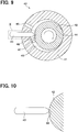
- a rotary compressor 40 includes a cylinder 41 which includes an inner wall having a cylindrical shape, a roller 42 which is disposed inside the cylinder 41, and a vane 43.
- the cylinder 41 and a pump chamber 45 are not illustrated.
- the vane 43 is reciprocatively disposed inside a hole formed on the cylinder 41.
- the vane 43 has a tip 48 which is in sliding contact with an outer wall of the roller 42, the outer wall being located on the outer side in the radial direction, to partition the pump chamber 45 which is formed between an inner wall of the cylinder 41 and the outer wall of the roller 42.
- the roller 42 swingably rotates in such a manner that a sliding contact point 44 between the inner wall of the cylinder 41 and the outer wall of the roller 42 moves in the circumferential direction.
- the sliding contact point 44 between the inner wall of the cylinder 41 and the outer wall of the roller 42 moves by 360°
- the refrigerant is sucked into the pump chamber 45 through a suction port 46.
- the sliding contact point 44 further rotates by 360°
- the refrigerant in the pump chamber 45 is compressed, and the high-pressure refrigerant is discharged through a discharge port 47.
- a pressure difference between the pressure of the refrigerant sucked through the suction port 46 and the pressure of the refrigerant discharged through the discharge port 47 is used as a force that presses the vane 43 against the outer wall of the roller 42 (that is, the back pressure of the vane 43).
- the vane 43 cannot follow the rotation of the roller 42, and a so-called vane jumping phenomenon is prone to occur.
- the pressure of the refrigerant sucked through the suction port 46 is referred to as the suction pressure.
- the pressure of the refrigerant discharged through the discharge port 47 is referred to as the discharge pressure.
- the refrigeration cycle device 1 of the third embodiment connects the first compressor 11 and the second compressor 12 in parallel when the cycle pressure difference ⁇ P is small in a manner similar to the control described in the second embodiment. Accordingly, as compared to a state in which the first compressor 11 and the second compressor 12 are connected in series, it is possible to increase the pressure difference between the suction pressure and the discharge pressure of each of the first compressor 11 and the second compressor 12 to increase the back pressure of the vane 43.
- the rotary compressor 40 when the rotary compressor 40 is employed as each of the first compressor 11 and the second compressor 12, the vane jumping described above is prevented. Thus, it is possible to prevent an increase of noise and prevent a reduction in the efficiency as a compressor.
- a fourth embodiment will be described.
- the fourth embodiment is also an example of the configuration of the compressor included in the refrigeration cycle device 1 described in the first and second embodiments.
- the other configuration is similar to that of the first and second embodiments.
- the configuration of the compressor will be described.
- At least one of a first compressor 11 and a second compressor 12 included in a refrigeration cycle device 1 of the fourth embodiment is a scroll compressor.
- a scroll compressor 50 includes a fixed scroll 51 having a spiral shape and an orbiting scroll 52 having a spiral shape, the orbiting scroll being disposed between wall surfaces of the fixed scroll 51.
- the orbiting scroll 52 swingably rotates in such a manner that a sliding contact point 53 between the fixed scroll 51 and the orbiting scroll 52 moves in the circumferential direction.
- FIG. 13 illustrate a state in which the sliding contact point 53 between the fixed scroll 51 and the orbiting scroll 52 moves by 360° by the operation of the orbiting scroll 52.
- the scroll compressor 50 when the sliding contact point 53 moves by 360°, the refrigerant is sucked into an outer region of a compression chamber, the outer region being located on the outer side in the radial direction, through a suction port 54 which is disposed on the outer side in the radial direction of the fixed scroll 51 and the orbiting scroll 52.
- the outer region of the compression chamber is denoted by ⁇ .
- the refrigerant moves from the intermediate region of the compression chamber to an inner region on the inner side in the radial direction of the intermediate region.
- the inner region of the compression chamber is denoted by ⁇ .
- the capacity of the intermediate region is smaller than the capacity of the outer region, and the capacity of the inner region is smaller than the capacity of the intermediate region.
- the capacity ratio between the capacity of the outer region where the compression of the refrigerant is started and the capacity of the inner region where the refrigerant is discharged from the compression chamber is determined in the capacity of the compression chamber which is formed between the fixed scroll 51 and the orbiting scroll 52.
- the scroll compressor 50 uses the discharge pressure of the refrigerant as a force that presses the fixed scroll 51 and the orbiting scroll 52 against each other in a rotation axis direction (that is, the back pressure of the scroll).
- the back pressure of the scroll is small.
- the refrigerant leakage occurs, specifically, the refrigerant in the compression chamber leaks through a gap between the fixed scroll 51 and the orbiting scroll 52, the compression efficiency of the compressor 50 may be reduced.
- the refrigeration cycle device 1 of the fourth embodiment also connects the first compressor 11 and the second compressor 12 in parallel when the cycle pressure difference ⁇ P is small in a manner similar to the control described in the second embodiment. Accordingly, as compared to a state in which the first compressor 11 and the second compressor 12 are connected in series, it is possible to increase the pressure difference between the suction pressure and the discharge pressure of each of the first compressor 11 and the second compressor 12. Thus, in the refrigeration cycle device 1 of the fourth embodiment, when the scroll compressor 50 is employed as each of the first compressor 11 and the second compressor 12, it is possible to prevent excessive compression and improve the coefficient of performance of the refrigeration cycle device 1.
- a fifth embodiment will be described.
- an example of the operation in the configuration of the refrigeration cycle device 1 described in the first embodiment will be described with reference to a flowchart of FIG. 14 .
- the control process is started when the activation/stop switch 37 disposed on the operation panel 36 outputs the start request signal.
- step S110 an initialization process of the control device 20 is performed.
- step S120 the control device 20 reads a detection signal of the in-storage temperature sensor 34, a detection signal of the outside air temperature sensor 35, and an operation signal of the temperature setting switch 38.
- an air temperature Tfr in the space to be cooled is defined as the in-storage temperature Tfr.
- step S130 the control device 20 determines which mode, the cool down mode or the in-range mode, should be executed. Specifically, the control device 20 determines whether a value obtained by subtracting the set temperature Tset from the in-storage temperature Tfr is larger than a first predetermined temperature t1. When the value obtained by subtracting the set temperature Tset from the in-storage temperature Tfr is larger than the first predetermined temperature t1, the control device 20 determines that the cool down mode which requires a large cooling capacity for cooling the in-storage space should be executed, and shifts the process to step S140.
- the first predetermined temperature t1 described above, and a second predetermined temperature t2 and a third predetermined temperature t3 which are described below are all appropriately set in advance by, for example, an experiment and stored in the memory of the control device 20.
- the first predetermined temperature t1, the second predetermined temperature t2, and the third predetermined temperature t3 may be different values or the same value.
- step S140 the control device 20 drives the switching unit 13 to bring the first compressor 11 and the second compressor 12 into a parallel connection state, and drives the first compressor 11 and the second compressor 12. Accordingly, the refrigeration cycle device 1 is brought into a state illustrated in FIG. 3 .
- the cool down mode is executed, the refrigerant discharged from the first compressor 11 flows to the first passage 21 without flowing to the second passage 22.
- the second compressor 12 which is disposed on the second passage 22 compresses only the refrigerant flowing into the second compressor 12 from the third passage 23.
- the intermediate heat exchanger 16 heat is exchanged between the refrigerant flowing through the third passage 23 and the refrigerant flowing through the fourth passage 24. Accordingly, the subcooling degree of the refrigerant flowing through the fourth passage 24 on the downstream side of the intermediate heat exchanger 16 increases.
- the refrigeration cycle device 1 is capable of increasing the cooling capacity.
- step S150 the control device 20 determines whether a value obtained by subtracting the in-storage temperature Tfr from the set temperature Tset is larger than the second predetermined temperature t2.
- the second predetermined temperature t2 is a value including zero.
- the control device 20 continues driving of the first compressor 11 and the second compressor 12. Thus, cooling of the in-storage space by the cool down mode is continuously executed.
- step S150 when the value obtained by subtracting the in-storage temperature Tfr from the set temperature Tset is larger than the second predetermined temperature t2 in step S150, the control device 20 shifts the process to step S160.
- step S160 the control device 20 stops driving of the first compressor 11 and the second compressor 12. Accordingly, cooling of the in-storage space by the cool down mode is stopped.
- the control device 20 continuously executes cooling of the in-storage space by the cool down mode until the in-storage temperature Tfr becomes the temperature obtained by subtracting the second predetermined temperature t2 from the set temperature Tset. Accordingly, in the control process executed by the control device 20 of the fifth embodiment, it is possible to lower the in-storage temperature Tfr to the set temperature Tset or less in a short time.
- step S170 the control device 20 determines whether the value obtained by subtracting the set temperature Tset from the in-storage temperature Tfr is larger than the third predetermined temperature t3.
- the control device 20 continues the driving stop state of the first compressor 11 and the second compressor 12.
- step S130 the control device 20 determines which mode, the cool down mode or the in-range mode, should be executed again.
- the control device 20 determines that the in-range mode should be executed, and shifts the process to step S180.
- the in-range mode in order to maintain the temperature in the in-storage space within a predetermined temperature range, it is possible to perform fine capacity control.
- step S180 the control device 20 brings the first compressor 11 and the second compressor 12 into a series connection state and drives the first compressor 11 and the second compressor 12. Accordingly, the refrigeration cycle device 1 is brought into a state illustrated in FIG. 4 .
- the refrigerant discharged from the first compressor 11 flows to the second passage 22 without flowing to the first passage 21.
- the second compressor 12 which is disposed on the second passage 22 compresses a mixture of the refrigerant discharged from the first compressor 11 and the refrigerant flowing into the second compressor 12 from the third passage 23.
- the control device 20 controls the rotation speed of each of the first compressor 11 and the second compressor 12 so that the refrigerant compression ratio by the first compressor 11 and the refrigerant compression ratio by the second compressor 12 become equal to or close to each other.
- the refrigeration cycle device 1 is capable of improving the coefficient of performance.
- step S190 the control device 20 determines whether the value obtained by subtracting the in-storage temperature Tfr from the set temperature Tset is larger than the second predetermined temperature t2.
- the control device 20 shifts the process to step S130.
- step S130 the control device 20 determines which mode, the cool down mode or the in-range mode, should be executed again.
- the control device 20 continuously executes the in-range mode.
- step S190 when the value obtained by subtracting the in-storage temperature Tfr from the set temperature Tset is larger than the second predetermined temperature t2 in step S190, the control device 20 shifts the process to step S200.
- step S200 the control device 20 stops driving of the first compressor 11 and the second compressor 12. Accordingly, cooling inside the freezer by the in-range mode is stopped.
- step S210 the control device 20 determines whether the value obtained by subtracting the set temperature Tset from the in-storage temperature Tfr is larger than the third predetermined temperature t3.
- the control device 20 continues the driving stop state of the first compressor 11 and the second compressor 12.
- step S210 when the value obtained by subtracting the set temperature Tset from the in-storage temperature Tfr is larger than the third predetermined temperature t3 in step S210, the control device 20 shifts the process to step S130.
- step S130 the control device 20 determines which mode, the cool down mode or the in-range mode, should be executed again.
- the control process described above is continuously executed until the stop request signal is output to the control device 20 from the operation panel 36.
- the control device 20 stops the operation of each device to be controlled to stop the entire system of the refrigerator.
- the in-storage temperature Tfr is higher than a temperature obtained by adding the first predetermined temperature t1 to the set temperature Tset.
- the control device 20 determines that the value obtained by subtracting the set temperature Tset from the in-storage temperature Tfr is larger than the first predetermined temperature t1, the control device 20 executes the cool down mode. That is, the control device 20 drives the switching unit 13 to bring the first compressor 11 and the second compressor 12 into a parallel connection state and drives the first compressor 11 and the second compressor 12.
- the control device 20 continuously executes cooling inside the freezer by the cool down mode until time T2.
- the in-storage temperature Tfr is a temperature obtained by subtracting the second predetermined temperature t2 from the set temperature Tset.
- the control device 20 determines that the value obtained by subtracting the in-storage temperature Tfr from the set temperature Tset is larger than the second predetermined temperature t2, the control device 20 stops driving of the first compressor 11 and the second compressor 12. That is, a thermostat-off state is established.
- the thermostat-off state continues until time T3.
- the in-storage temperature Tfr is a temperature obtained by adding the second predetermined temperature t2 to the set temperature Tset.
- the control device 20 determines that the value obtained by subtracting the set temperature Tset from the in-storage temperature Tfr is larger than the third predetermined temperature t3, the control device 20 executes the in-range mode. That is, the control device 20 drives the switching unit 13 to bring the first compressor 11 and the second compressor 12 into a series connection state and drives the first compressor 11 and the second compressor 12.
- the control device 20 executes cooling inside the freezer by the in-range mode until time T4.
- the in-storage temperature Tfr is a temperature obtained by subtracting the second predetermined temperature t2 from the set temperature Tset.
- the control device 20 determines that the value obtained by subtracting the in-storage temperature Tfr from the set temperature Tset is larger than the second predetermined temperature t2, the control device 20 stops driving of the first compressor 11 and the second compressor 12. That is, a thermostat-off state is established.
- the in-storage temperature Tfr is higher than a temperature obtained by adding the first predetermined temperature t1 to the set temperature Tset.
- the control device 20 determines that the value obtained by subtracting the set temperature Tset from the in-storage temperature Tfr is larger than the first predetermined temperature t1, the control device 20 executes the cool down mode. That is, the control device 20 drives the switching unit 13 to bring the first compressor 11 and the second compressor 12 into a parallel connection state and drives the first compressor 11 and the second compressor 12.
- the control device 20 executes cooling inside the freezer by the cool down mode until time T11.
- the in-storage temperature Tfr is the temperature obtained by adding the first predetermined temperature t1 to the set temperature Tset.
- the control device 20 executes the in-range mode. That is, the control device 20 drives the switching unit 13 to bring the first compressor 11 and the second compressor 12 into a series connection state and drives the first compressor 11 and the second compressor 12.
- the control device 20 executes cooling inside the freezer by the in-range mode until time T12.
- the in-storage temperature Tfr is a temperature obtained by subtracting the second predetermined temperature t2 from the set temperature Tset.
- the control device 20 stops driving of the first compressor 11 and the second compressor 12. That is, a thermostat-off state is established.
- the transition of the in-storage temperature Tfr and the control process by the control device 20 of the comparative example after time T12 are the same as the transition and the control process after time T2 described in the fifth embodiment.
- the cool down mode is switched to the in-range mode.
- a time required for the in-storage temperature Tfr to become the set temperature Tset or less may become long.
- the control method by the refrigeration cycle device 1 of the fifth embodiment achieves the following effect.
- the control device 20 when the control device 20 executes the cool down mode, the control device 20 drives the first compressor 11 and the second compressor 12 until the in-storage temperature Tfr becomes lower than the value obtained by subtracting the second predetermined temperature t2 from the set temperature Tset. Then, when the in-storage temperature Tfr becomes lower than the value obtained by subtracting the second predetermined temperature t2 from the set temperature Tset, the control device 20 stops driving of the first compressor 11 and the second compressor 12. Accordingly, in the fifth embodiment, it is possible to lower the in-storage temperature Tfr to the set temperature Tset or less in a short time.
- a sixth embodiment will be described.
- the configuration and the operation of the refrigeration cycle device 1 of the first or second embodiment are partially modified.
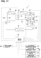
- a refrigeration cycle device 1 of the sixth embodiment includes a vane failure detector 60 for detecting vane failure of the first compressor 11 and the second compressor 12.
- a vane failure detector 60 for detecting vane failure of the first compressor 11 and the second compressor 12.
- a noise measuring instrument which measures noise of the first compressor 11 and the second compressor 12 or a vibration measuring instrument which measure vibrations of the first compressor 11 and the second compressor 12 can be employed as the vane failure detector 60.
- a flow rate measuring instrument which measures a flow rate of a refrigerant circulating through the refrigeration cycle device 1 can also be employed as the vane failure detector 60.
- a signal output from the vane failure detector 60 is transmitted to the control device 20.
- the control device 20 determines whether vane failure is occurring in the first compressor 11 or the second compressor 12 on the basis of the signal.
- the control device 20 when the noise measuring instrument is employed as the vane failure detector 60, the control device 20 is capable of determining occurrence of vane failure when a sound pressure in a predetermined frequency band is larger than a certain sound pressure in noise measured by the noise measuring instrument.
- the control device 20 When the vibration measuring instrument is employed as the vane failure detector 60, the control device 20 is capable of determining occurrence of vane failure when vibration measured by the vibration measuring instrument is larger than a certain amplitude.
- the control device 20 When the flow rate measuring instrument is employed as the vane failure detector 60, the control device 20 is capable of determining occurrence of vane failure when a flow rate of the refrigerant measured by the flow rate measuring instrument is lower than a certain flow rate.
- the predetermined frequency band, the certain sound pressure, the certain amplitude, and the certain flow rate described above are set in advance by, for example, an experiment and stored in the memory of the control device 20.
- FIG. 18 is a flowchart illustrating a control process executed by the control device 20 of the sixth embodiment.
- the control process is started when a start request signal is output by the activation/stop switch 37 of the operation panel 36.
- step S10 an initialization process of the control device 20 is performed.
- step S15 the refrigeration cycle device 1 performs cooling of the in-storage space.
- the first compressor 11 and the second compressor 12 may be connected in parallel when the cool down mode is executed and connected in series when the in-range mode is executed.
- the first compressor 11 and the second compressor 12 may be connected in series when the cycle pressure difference ⁇ P is larger than the predetermined pressure Pth and connected in parallel when the cycle pressure difference ⁇ P is smaller than the predetermined pressure Pth.
- step S25 the control device 20 reads a signal transmitted from the vane failure detector 60.
- step S35 the control device 20 determines whether vane failure is occurring in the first compressor 11 or the second compressor 12 on the basis of the signal. Any of the methods described above can be employed as a method for determining vane failure.
- step S40 the control device 20 causes the switching unit 13 to switch the refrigerant flow passage so that the first compressor 11 and the second compressor 12 are connected in parallel.
- step S55 the control device 20 maintains the switching unit 13 in a current state. That is, when the first compressor 11 and the second compressor 12 are connected in series in the current state, the control device 20 maintains the series connection. Further, when the first compressor 11 and the second compressor 12 are connected in parallel in the current state, the control device 20 maintains the parallel connection.
- Step S60 is the same as the process described in the first embodiment. Thus, description thereof will be omitted.
- control device 20 is capable of directly detecting vane failure of the first compressor 11 or the second compressor 12 by the vane failure detector 60 and coping with the vane failure.
- a seventh embodiment will be described.
- the control process described in the second embodiment will be described in more detail.
- description will be made with reference to the flow chart of FIG. 5 referred to in the second embodiment again.
- the control process of the seventh embodiment is started also when the activation/stop switch 37 of the operation panel 36 outputs a start request signal.
- step S10 an initialization process of the control device 20 is performed.
- step S21 the control device 20 reads a detection signal of the first pressure sensor 31 and a detection signal of the second pressure sensor 32. Then, the control device 20 calculates the difference between a pressure detected by the detection signal of the first pressure sensor 31 and a pressure detected by the second pressure sensor 32, that is, the cycle pressure difference ⁇ P.
- step S31 the control device 20 determines whether the first compressor 11 and the second compressor 12 should be connected in parallel or series according to whether the cycle pressure difference ⁇ P is smaller than the predetermined pressure Pth.
- the control device 20 of the seventh embodiment determines the predetermined pressure Pth on the basis of a rotation speed of the first compressor 11 and a rotation speed of the second compressor 12.
- FIG. 19 illustrates the relationship between the rotation speed of the first compressor 11 and a necessary pressure difference necessary for the first compressor 11 to avoid vane failure.
- the pressure difference necessary for the first compressor 11 to avoid vane failure at a predetermined rotation speed RS1 is referred to as a first necessary pressure difference Pth1.
- the first necessary pressure difference Pth1 corresponding to the rotation speed RS1 increases.
- FIG. 20 illustrates the relationship between the rotation speed of the second compressor 12 and a necessary pressure difference necessary for the second compressor 12 to avoid vane failure.
- the pressure difference necessary for the second compressor 12 to avoid vane failure at a predetermined rotation speed RS2 is referred to as a second necessary pressure difference Pth2.
- the second necessary pressure difference Pth2 corresponding to the rotation speed RS2 increases.
- the relationship between the rotation speed RS1 and the first necessary pressure difference Pth1 of the first compressor 11 and the relationship between the rotation speed RS2 and the second necessary pressure difference Pth2 of the second compressor 12 are set in advance by, for example, an experiment and stored in the memory of the control device 20.
- the control device 20 detects the first necessary pressure difference Pth1 of the first compressor 11 on the basis of the rotation speed RS1 of the first compressor 11.
- the control device 20 detects the second necessary pressure difference Pth2 of the second compressor 12 on the basis of the rotation speed RS2 of the second compressor 12. Then, the control device 20 defines the sum of the first necessary pressure difference Pth1 and the second necessary pressure difference Pth2 as the predetermined pressure Pth.
- step S21 When the cycle pressure difference ⁇ P calculated in step S21 is larger than the predetermined pressure Pth, the control device 20 shifts the process to step S50.
- step S50 the control device 20 drives and controls the switching unit 13 to bring the first compressor 11 and the second compressor 12 into a series connection state.
- step S21 when the cycle pressure difference ⁇ P calculated in step S21 is smaller than the predetermined pressure Pth, the control device 20 shifts the process to step S40.
- step S50 the control device 20 drives and controls the switching unit 13 to bring the first compressor 11 and the second compressor 12 into a parallel connection state.
- Step S60 is the same as the process described in the first embodiment. Thus, description thereof will be omitted.
- the control device 20 determines whether the first compressor 11 and the second compressor 12 should be connected in parallel or series according to whether the cycle pressure difference ⁇ P is smaller than the predetermined pressure Pth. Further, the predetermined pressure Pth is the sum of the first necessary pressure difference Pth1 which is determined on the basis of the rotation speed RS1 of the first compressor 11 and the second necessary pressure difference Pth2 which is determined on the basis of the rotation speed RS2 of the second compressor 12. Accordingly, in the seventh embodiment, it is possible to avoid vane failure of the first compressor 11 and the second compressor 12.
- the first compressor compresses and discharges a refrigerant.
- the switching unit is disposed on a discharge side of the first compressor and switches a flow of the refrigerant discharged from the first compressor to a first passage or a second passage.
- the second compressor is disposed on a middle of the second passage, and compresses and discharges the refrigerant flowing through the second passage.
- the first connector connects a part of the second passage on a discharge side of the second compressor and the first passage.
- the condenser exchanges heat between the refrigerant flowing into the condenser from the first connector and outside air.
- the branch unit divides a flow passage on an outlet side of the condenser to a third passage and a fourth passage.
- the first expansion valve is disposed on a middle of the third passage and decompresses the refrigerant flowing through the third passage.
- the intermediate heat exchanger exchanges heat between the refrigerant flowing through the third passage on a downstream side of the first expansion valve and the refrigerant flowing through the fourth passage.
- the second connector connects a part of the second passage on a suction side of the second compressor and a part of the third passage on a downstream side of the intermediate heat exchanger.
- the second expansion valve is disposed on the downstream side of the intermediate heat exchanger on the fourth passage and decompresses the refrigerant flowing through the fourth passage.
- the evaporator is disposed on a downstream side of the second expansion valve on the fourth passage, exchanges heat between the refrigerant flowing through the fourth passage and air in the space to be cooled, and discharges the refrigerant toward a suction side of the first compressor.
- the refrigeration cycle device further includes a control device that controls the switching unit.
- the control device controls the switching unit so that the refrigerant discharged from the first compressor flows to the second passage when a difference between a set temperature set as a target value for cooling an air temperature in the space to be cooled and the air temperature in the space to be cooled is smaller than a predetermined temperature.
- the control device controls the switching unit so that the refrigerant discharged from the first compressor flows to the first passage when the difference between the air temperature in the space to be cooled and the set temperature is larger than the predetermined temperature.
- the control device when the difference between the air temperature in the space to be cooled and the set temperature is smaller than the predetermined temperature, that is, during an in-range mode which does not require a large cooling capacity, the control device connects the first compressor and the second compressor in series. Accordingly, it is possible to reduce the refrigerant compression ratio by each of the compressors, which improves the refrigerant compression efficiency of each of the first compressor and the second compressor. Thus, the refrigeration cycle device is capable of improving the coefficient of performance.
- the control device connects the first compressor and the second compressor in parallel. Accordingly, it is possible to increase the subcooling degree of the refrigerant flowing through the fourth passage on the downstream side of the intermediate heat exchanger.
- the refrigeration cycle device is capable of increasing the cooling capacity to bring the air temperature in the space to be cooled close to the set temperature in a short time.
- the refrigeration cycle device further includes a control device that controls the switching unit, a first pressure sensor that detects a pressure of the refrigerant from the discharge side of the second compressor to the second expansion valve, and a second pressure sensor that detects a pressure of the refrigerant from the downstream side of the second expansion valve to the first compressor.
- the control device controls the switching unit so that the refrigerant discharged from the first compressor flows to the second passage when a difference between the pressure detected by the first pressure sensor and the pressure detected by the second pressure sensor (that is, the cycle pressure difference) is larger than a predetermined pressure.
- control device controls the switching unit so that the refrigerant discharged from the first compressor flows to the first passage when the difference between the pressure detected by the first pressure sensor and the pressure detected by the second pressure sensor (that is, the cycle pressure difference) is smaller than the predetermined pressure.
- the control device when the cycle pressure difference is larger than the predetermined pressure, the control device connects the first compressor and the second compressor in series. Accordingly, the refrigerant compression efficiency of each of the first compressor and the second compressor is improved.
- the refrigeration cycle device is capable of improving the coefficient of performance.
- the control device connects the first compressor and the second compressor in parallel. Accordingly, it is possible to increase the subcooling degree of the refrigerant flowing through the fourth passage on the downstream side relative to the intermediate heat exchanger by reducing the refrigerant pressure on the downstream side relative to the first expansion valve on the third passage lower than the refrigerant pressure on the discharge side of the first compressor.
- the refrigeration cycle device is capable of increasing the cooling capability for cooling air in the space to be cooled even when the cycle pressure difference is small. In this case, since the cycle pressure difference is small, an increase in the refrigerant compression ratio by each of the first compressor and the second compressor is prevented, and an increase in energy consumption of each of the first compressor and the second compressor is small.
- At least one of the first compressor and the second compressor is a rotary compressor.
- the rotary compressor includes a cylinder including an inner wall having a cylindrical shape, a roller disposed inside the cylinder, and a vane that partitions a pump chamber formed between the inner wall of the cylinder and an outer wall of the roller.
- the roller operates in such a manner that a sliding contact point between the inner wall of the cylinder and the outer wall of the roller moves in a circumferential direction.
- the refrigeration cycle device when the cycle pressure difference is small, is capable of increasing the pressure difference between the suction pressure and the discharge pressure of each of the first compressor and the second compressor by connecting the first compressor and the second compressor in parallel as compared to a state in which the first compressor and the second compressor are connected in series. Accordingly, in the rotary compressor, it is possible to increase the back pressure of the vane, which prevents vane failure. Thus, the refrigeration cycle device is capable of preventing an increase of noise in the rotary compressor and preventing a reduction in the compression efficiency of the rotary compressor.
- At least one of the first compressor and the second compressor is a scroll compressor.
- the scroll compressor includes a fixed scroll having a spiral shape and an orbiting scroll having a spiral shape, the orbiting scroll being disposed between walls of the fixed scroll.
- the orbiting scroll operates in such a manner that a sliding contact point between the fixed scroll and the orbiting scroll moves in a circumferential direction.
- the scroll compressor it is possible to increase the back pressure of the scroll by increasing the pressure difference between the suction pressure and the discharge pressure, which prevents a refrigerant leakage through a gap between the fixed scroll and the orbiting scroll.
- the scroll compressor excessive compression of the refrigerant is prevented by increasing the pressure difference between the suction pressure and the discharge pressure.
- the refrigeration cycle device further includes a control device that controls the switching unit.
- the control device controls the switching unit so that the refrigerant discharged from the first compressor flows to the first passage and drives the first compressor and the second compressor
- the control device continues a current state until the air temperature in the space to be cooled becomes the set temperature or less and then stops driving of the first compressor and the second compressor.
- the refrigeration cycle device is capable of lowering the air temperature in the space to be cooled to the set temperature or less in a short time.
- the refrigeration cycle device further includes a control device that controls the switching unit, and a vane failure detector that detects occurrence of vane failure in the rotary compressor.
- the control device controls the switching unit so that the refrigerant discharged from the first compressor flows to the first passage.
- the refrigeration cycle device is capable of directly detecting vane failure of the first compressor or the second compressor by the vane failure detector and coping with the vane failure.
- the predetermined pressure compared with the cycle pressure difference by the control device is a sum of a first necessary pressure difference determined on the basis of a rotation speed of the first compressor and a second necessary pressure difference determined on the basis of a rotation speed of the second compressor.
- the first necessary pressure difference is set to a larger value as the rotation speed of the first compressor increases.
- the second necessary pressure difference is also set to a larger value as the rotation speed of the second compressor increases.
Landscapes
- Engineering & Computer Science (AREA)
- Physics & Mathematics (AREA)
- Mechanical Engineering (AREA)
- Thermal Sciences (AREA)
- General Engineering & Computer Science (AREA)
- Applications Or Details Of Rotary Compressors (AREA)
- Control Of Positive-Displacement Pumps (AREA)
Abstract
Description
- This application is based on Japanese Patent Application No.
2017-11594 filed on January 25, 2017 2017-199593 filed on October 13, 2017 - The present disclosure relates to a refrigeration cycle device including plural compressors.
- Conventionally, a refrigeration cycle device is known, which includes plural compressors to compress refrigerant.
- A refrigeration cycle device described in
Patent Literature 1 includes flow passage switching means for switching a connection state between two compressors to a parallel connection state or a series connection state, the flow passage switching means including six connection ports. The refrigeration cycle device connects the two compressors in series by the operation of the flow passage switching means during a cooling operation and constitutes a so-called economizer refrigeration cycle using an intermediate heat exchanger. In the economizer refrigeration cycle, part of a refrigerant flowing on the downstream side of an outdoor heat exchanger is diverted, decompressed by a capillary tube, and then introduced into the intermediate heat exchanger. The refrigerant flowing out of the intermediate heat exchanger and a refrigerant discharged from the low-stage side compressor are mixed and flow into the high-stage side compressor. Accordingly, the refrigeration cycle device reduces an enthalpy of the refrigerant to increase a cooling capacity during the cooling operation. - On the other hand, the refrigeration cycle device connects the two compressors in parallel by the operation of the flow passage switching means during a heating operation. At this time, the intermediate heat exchanger is used as a mere refrigerant passage.
- Patent Literature 1 :
JP H09-145189A - However, the refrigeration cycle device described in
Patent Literature 1 has a complicated structure in which the flow passage switching means switches flow passages connected to the six connection ports. Further, in the refrigeration cycle device, piping for connecting the two compressors, the flow passage switching means, and the outdoor heat exchanger has a complicated configuration. - Further, in the refrigeration cycle device described in
Patent Literature 1, the intermediate heat exchanger is fully utilized only when the two compressors are connected in series and used as a mere refrigerant passage when the two compressors are connected in parallel. That is, in the refrigeration cycle device, the intermediate heat exchanger is not effectively utilized. - It is an object of the present disclosure to provide a refrigeration cycle device that makes it possible to simplify a configuration for switching a connection state between a plurality of compressors to a series connection state or a parallel connection state and effectively utilize an intermediate heat exchanger in any connection state.
- According to an aspect of the present disclosure, a refrigeration cycle device that cools air in a space to be cooled includes:
- a first compressor that compresses and discharges a refrigerant;
- a switching unit that is disposed on a discharge side of the first compressor and switches a flow of the refrigerant discharged from the first compressor to a first passage or a second passage;
- a second compressor that is disposed on a middle of the second passage, and compresses and discharges the refrigerant flowing through the second passage;
- a first connector that connects a part of the second passage on a discharge side of the second compressor and the first passage;
- a condenser that exchanges heat between the refrigerant flowing into the condenser from the first connector and outside air;
- a branch unit that divides a flow passage on an outlet side of the condenser to a third passage and a fourth passage;
- a first expansion valve that is disposed on a middle of the third passage and decompresses the refrigerant flowing through the third passage;
- an intermediate heat exchanger that exchanges heat between the refrigerant flowing through the third passage on a downstream side of the first expansion valve and the refrigerant flowing through the fourth passage;
- a second connector that connects a part of the second passage on a suction side of the second compressor and a part of the third passage on a downstream side of the intermediate heat exchanger;
- a second expansion valve that is disposed on the downstream side of the intermediate heat exchanger on the fourth passage and decompresses the refrigerant flowing through the fourth passage; and
- an evaporator that is disposed on a downstream side of the second expansion valve on the fourth passage, exchanges heat between the refrigerant flowing through the fourth passage and air in the space to be cooled, and discharges the refrigerant toward a suction side of the first compressor.
- According to the above configuration, since the refrigeration cycle device includes the first passage, the second passage, and the switching unit for switching the two passages, the refrigeration cycle device is capable of switching a connection state between the first compressor and the second compressor to a series connection state or a parallel connection state. Thus, the refrigeration cycle device makes it possible to simplify the configuration of the switching unit and the configuration of piping for switching the connection state between the plurality of compressors to a series connection state or a parallel connection state.
- Further, in the refrigeration cycle device, the intermediate heat exchanger exchanges heat between the refrigerant flowing through the third passage on the downstream side relative to the first expansion valve and the refrigerant flowing through the fourth passage on the upstream side relative to the second expansion valve in any of the series connection state and the parallel connection state between the compressors. Thus, a subcooling degree of the refrigerant flowing through the fourth passage on the downstream side of the intermediate heat exchanger increases. Thus, the refrigeration cycle device is capable of increasing the cooling capability for cooling air in the space to be cooled by effectively utilizing the intermediate heat exchanger in any of the series connection state and the parallel connection state between the compressors.
-
-
FIG. 1 is a diagram illustrating the configuration of a refrigeration cycle device in a first embodiment. -
FIG. 2 is a flowchart illustrating a control method of the refrigeration cycle device in the first embodiment. -
FIG. 3 is a diagram illustrating a state in which a first compressor and a second compressor are connected in parallel. -
FIG. 4 is a diagram illustrating a state in which the first compressor and the second compressor are connected in series. -
FIG. 5 is a flowchart illustrating a control method of a refrigeration cycle device in a second embodiment. -
FIG. 6 is a Mollier diagram illustrating the behavior of a refrigerant when a first compressor and a second compressor are connected in series. -
FIG. 7 is a Mollier diagram illustrating the behavior of the refrigerant when the first compressor and the second compressor are connected in series in a state in which a cycle pressure difference is small. -
FIG. 8 is a Mollier diagram illustrating the behavior of the refrigerant when the first compressor and the second compressor are connected in parallel in a state in which the cycle pressure difference is small. -
FIG. 9 is a sectional view illustrating the configuration of a rotary compressor included in a refrigeration cycle device in a third embodiment. -
FIG. 10 is an enlarged view of a part X ofFIG. 9 . -
FIG. 11 is a sectional view illustrating the configuration of a scroll compressor included in a refrigeration cycle device in a fourth embodiment. -
FIG. 12 is a sectional view taken along line XII-XII ofFIG. 11 . -
FIG. 13 is an explanatory diagram describing the operation of the scroll compressor. -
FIG. 14 is a flowchart illustrating the operation of a refrigeration cycle device in a fifth embodiment. -
FIG. 15 is a graph illustrating an example of a transition of an in-storage temperature by the operation of the refrigeration cycle device in the fifth embodiment. -
FIG. 16 is a graph illustrating an example of a transition of an in-storage temperature by the operation of a refrigeration cycle device of a comparative example. -
FIG. 17 is a diagram illustrating the configuration of a refrigeration cycle device in a sixth embodiment. -
FIG. 18 is a flowchart illustrating the operation of the refrigeration cycle device in the sixth embodiment. -
FIG. 19 is a graph illustrating the relationship between a rotation speed of a first compressor included in a refrigeration cycle device in a seventh embodiment and a first necessary pressure difference necessary for avoiding vane failure. -
FIG. 20 is a graph illustrating the relationship between a rotation speed of a second compressor included in the refrigeration cycle device in the seventh embodiment and a second necessary pressure difference necessary for avoiding vane failure. - Hereinafter, embodiments will be described according to the drawings. Same or equivalent portions among respective embodiments below are labeled with same reference numerals in the drawings.
- A first embodiment will be described. A refrigeration cycle device of the first embodiment is used in a refrigerator which cools air in a freezer as a space to be cooled and has a function of cooling an in-storage temperature of the freezer to a very low temperature, for example, approximately -30°C to -10°C.
- As illustrated in
FIG. 1 , therefrigeration cycle device 1 includes afirst compressor 11, asecond compressor 12, a switchingunit 13, acondenser 14, afirst expansion valve 15, anintermediate heat exchanger 16, asecond expansion valve 17, and anevaporator 18 which are connected through, for example, pipes. For example, a fluorocarbon refrigerant such as R404A can be employed as a refrigerant circulating through therefrigeration cycle device 1. Each component of therefrigeration cycle device 1 is driven and controlled by acontrol device 20. InFIG. 1 , a signal line between thecontrol device 20 and each component is indicated by a broken line. - The
first compressor 11 and thesecond compressor 12 are both electric compressors. Each of thefirst compressor 11 and thesecond compressor 12 includes a refrigerant compression mechanism (not illustrated) and an electric motor (not illustrated) for rotating the refrigerant compression mechanism. The refrigerant compression mechanism is driven to rotate by the electric motor to compress the refrigerant sucked through a suction port and discharge the refrigerant through a discharge port. The refrigerant compression mechanism is a fixed displacement compression mechanism whose discharge capacity is fixed. For example, a rotary or scroll compression mechanism can be employed as the refrigerant compression mechanism. The electric motor is driven and controlled by thecontrol device 20. A refrigerant discharge amount of each of thefirst compressor 11 and thesecond compressor 12 is varied by controlling a rotation speed of the electric motor by thecontrol device 20. - The switching
unit 13 is disposed on the discharge side of thefirst compressor 11. The switchingunit 13 of the present embodiment is a flow passage switching valve which includes aninflow port 130, afirst outflow port 131, and asecond outflow port 132. When the switchingunit 13 causes theinflow port 130 and thefirst outflow port 131 to communicate with each other, the switchingunit 13 interrupts communication between theinflow port 130 and thesecond outflow port 132. When the switchingunit 13 interrupts communication between theinflow port 130 and thefirst outflow port 131, the switchingunit 13 causes theinflow port 130 and thesecond outflow port 132 to communicate with each other. The switchingunit 13 is, for example, a three-way valve. - The
inflow port 130 is connected to a passage on the discharge side of thefirst compressor 11. Thefirst outflow port 131 is connected to afirst passage 21, and thesecond outflow port 132 is connected to asecond passage 22. Thus, the switchingunit 13 is capable of switching the flow of the refrigerant discharged from thefirst compressor 11 to thefirst passage 21 or thesecond passage 22. - The
second compressor 12 is disposed on the middle of thesecond passage 22. Thesecond compressor 12 compresses and discharges the refrigerant flowing through thesecond passage 22. - A part of the
second passage 22 on the discharge side of thesecond compressor 12, a part of thefirst passage 21 on the side opposite to theswitching unit 13, and a passage on the inlet side of thecondenser 14 are connected by afirst connector 25 which is a three-way joint. Accordingly, the refrigerant flowing through thefirst passage 21 or thesecond passage 22 flows into thecondenser 14 via thefirst connector 25. - In the present embodiment, the
first passage 21 connects thefirst outflow port 131 of the switchingunit 13 and thefirst connector 25 to each other. Thesecond passage 22 connects thesecond outflow port 132 of the switchingunit 13 and thefirst connector 25 to each other. - On the
second passage 22, asecond connector 26 which is a three-way joint is disposed between thesecond outflow port 132 of the switchingunit 13 and a suction port of thesecond compressor 12. Thesecond connector 26 connects thesecond passage 22 and a third passage 23 (described below). Thus, thesecond connector 26 connects a part of thesecond passage 22 on the suction side of thesecond compressor 12 and a part of thethird passage 23 on the downstream side of theintermediate heat exchanger 16. - The
first connector 25 and thesecond connector 26 may include plural pipes joined together or plural flow passages formed on a metal block or a resin block. - The
condenser 14 is a radiation heat exchanger which exchanges heat between the refrigerant flowing through a refrigerant passage (not illustrated) formed inside thecondenser 14 and air outside the freezer (that is, the outside air) to radiate heat of the high-pressure refrigerant to the outside air. The high-pressure refrigerant flowing through the refrigerant passage inside thecondenser 14 is cooled and condensed by radiating heat to the outside air. - The flow passage on the outlet side of the
condenser 14 is divided into thethird passage 23 and afourth passage 24 by abranch unit 27. That is, the passage on the outlet side of thecondenser 14, thethird passage 23, and thefourth passage 24 are connected by thebranch unit 27 which is a three-way joint. Accordingly, the refrigerant flowing out of the outlet side of thecondenser 14 is divided into thethird passage 23 and thefourth passage 24. Thebranch unit 27 may include plural pipes joined together or plural flow passages formed on a metal block or a resin block. - In the present embodiment, the
third passage 23 connects thebranch unit 27 and thesecond connector 26 to each other. Thefourth passage 24 connects thebranch unit 27 and a suction port of thefirst compressor 11 to each other. - The
first expansion valve 15 for decompressing the refrigerant flowing through thethird passage 23 is disposed on the middle of thethird passage 23. The refrigerant decompressed by thefirst expansion valve 15 becomes a gas-liquid two-phase state and flows into theintermediate heat exchanger 16. That is, thefirst expansion valve 15 is disposed on the upstream side of theintermediate heat exchanger 16 on thethird passage 23. - On the other hand, the refrigerant flowing through the
fourth passage 24 also flows into theintermediate heat exchanger 16. On thefourth passage 24, thesecond expansion valve 17 for decompressing the refrigerant flowing through thefourth passage 24 is disposed on the downstream side of theintermediate heat exchanger 16. - The
first expansion valve 15 and thesecond expansion valve 17 are flow control valves capable of mechanically or electrically controlling a refrigerant flow rate. For example, thefirst expansion valve 15 changes a valve opening degree by a mechanical mechanism to control the refrigerant flow rate on the basis of the temperature and the pressure of the refrigerant on the outlet side of theintermediate heat exchanger 16. Thesecond expansion valve 17 changes a valve opening degree by a mechanical mechanism to control the refrigerant flow rate on the basis of the temperature and the pressure of the refrigerant on the outlet side of theevaporator 18. - In the
intermediate heat exchanger 16, heat is exchanged between the refrigerant flowing through thethird passage 23 on the downstream side relative to thefirst expansion valve 15 and the refrigerant flowing through thefourth passage 24 on the upstream side relative to thesecond expansion valve 17. That is, in theintermediate heat exchanger 16, heat is exchanged between the refrigerant that has been decompressed by thefirst expansion valve 15 and brought into a gas-liquid two-phase state on thethird passage 23 and the high-temperature and high-pressure refrigerant flowing through thefourth passage 24. Accordingly, a subcooling degree of the refrigerant flowing through thefourth passage 24 increases. - The
intermediate heat exchanger 16 illustrated inFIG. 1 is a counterflow heat exchanger in which a flow direction of the refrigerant flowing through thethird passage 23 is opposite to a flow direction of the refrigerant flowing through thefourth passage 24. In theintermediate heat exchanger 16, the refrigerant flowing through thethird passage 23 and the refrigerant flowing through thefourth passage 24 exchange heat without being mixed. Theintermediate heat exchanger 16 may be a parallel flow heat exchanger in which the flow direction of the refrigerant flowing through thethird passage 23 is the same as the flow direction of the refrigerant flowing through thefourth passage 24. - The refrigerant flowing through the
third passage 23 on the downstream side of theintermediate heat exchanger 16 flows into thesecond passage 22 through thesecond connector 26. A check valve (not illustrated) may be disposed between theintermediate heat exchanger 16 and thesecond connector 26 on thethird passage 23. - On the other hand, the refrigerant flowing through the
fourth passage 24 on the downstream side of theintermediate heat exchanger 16 is decompressed by thesecond expansion valve 17 and brought into a gas-liquid two-phase state, and flows into theevaporator 18. - The
evaporator 18 is disposed on the downstream side of thesecond expansion valve 17 on thefourth passage 24. In theevaporator 18, heat is exchanged between the refrigerant that has been decompressed by thesecond expansion valve 17 and brought into a gas-liquid two-phase state on thefourth passage 24 and air circulating through the freezer as the space to be cooled. Accordingly, air in the space to be cooled is cooled. A part of thefourth passage 24 on the downstream side of theevaporator 18 is connected to the suction port of thefirst compressor 11. Thus, the refrigerant flowing out of theevaporator 18 toward thefirst compressor 11 is sucked into the suction port of thefirst compressor 11. - The
refrigeration cycle device 1 is provided with a plurality of pressure sensors for detecting the pressure of the refrigerant. Specifically, afirst pressure sensor 31 is disposed on a part of thesecond passage 22 on the discharge side of thesecond compressor 12. Thefirst pressure sensor 31 detects the pressure of the refrigerant discharged from thesecond compressor 12. Thefirst pressure sensor 31 only needs to be disposed on a passage between the discharge side of thesecond compressor 12 and thesecond expansion valve 17. - A
second pressure sensor 32 is disposed on a part of thefourth passage 24 on the downstream side of theevaporator 18. Thesecond pressure sensor 32 detects the pressure of the refrigerant decompressed by thesecond expansion valve 17. Thesecond pressure sensor 32 only needs to be disposed on a passage between the downstream side of thesecond expansion valve 17 and thefirst compressor 11. - A
third pressure sensor 33 is disposed on a part of thethird passage 23 on the downstream side of theintermediate heat exchanger 16. Thethird pressure sensor 33 detects the pressure of the refrigerant decompressed by thefirst expansion valve 15. Thethird pressure sensor 33 only needs to be disposed on a passage between the downstream side of thefirst expansion valve 15 and thesecond compressor 12. - All detection signals output from the first to
third pressure sensors 33 are input to thecontrol device 20. - The
control device 20 includes a microcomputer which includes a CPU and a memory such as a ROM and a RAM, and a peripheral circuit thereof. Thecontrol device 20 performs various operations and processes in accordance with a control program stored in the memory to control the operation of a device to be controlled which is connected to the output side. The memory of thecontrol device 20 includes a non-transitory tangible storage medium. - A detection signal of an in-
storage temperature sensor 34 which detects an air temperature Tfr in the space to be cooled and a detection signal of an outsideair temperature sensor 35 which detects the temperature of the outside air which exchanges heat with the high-pressure refrigerant in thecondenser 14 are input to thecontrol device 20. - The
control device 20 is electrically connected to anoperation panel 36. Theoperation panel 36 is provided with an activation/stop switch 37 which outputs a start request signal or a stop request signal for the freezer and atemperature setting switch 38 for setting a set temperature Tset which is set as a target value for cooling the air temperature in the space to be cooled. An operation signal of the activation/stop switch 37 and an operation signal of thetemperature setting switch 38 are also input to thecontrol device 20. - Hereinbelow, the operation of the
refrigeration cycle device 1 of the first embodiment will be described with reference to a flowchart ofFIG. 2. FIG. 2 is a flowchart illustrating a control process executed by thecontrol device 20. - The control process is started when the activation/
stop switch 37 disposed on theoperation panel 36 outputs the start request signal. First, in step S10, an initialization process of thecontrol device 20 is performed. Next, in step S20, thecontrol device 20 reads a detection signal of the in-storage temperature sensor 34, a detection signal of the outsideair temperature sensor 35, an operation signal of thetemperature setting switch 38, and the like. - Then, in step S30, the
control device 20 determines whether the difference between the air temperature Tfr in the space to be cooled and the set temperature Tset is larger than a predetermined temperature Tth. The predetermined temperature Tth is appropriately determined in advance by, for example, an experiment and stored in the memory of thecontrol device 20. When the difference between the air temperature Tfr in the space to be cooled and the set temperature Tset is larger than the predetermined temperature Tth, thecontrol device 20 determines that a cool down mode which requires a large cooling capacity should be executed and shifts the process to step S40. - In step S40, the
control device 20 drives the switchingunit 13 so that communication between theinflow port 130 and thesecond outflow port 132 of the switchingunit 13 is interrupted and theinflow port 130 and thefirst outflow port 131 communicate with each other. That is, thecontrol device 20 drives the switchingunit 13 to bring thefirst compressor 11 and thesecond compressor 12 into a parallel connection state. The state at this time is illustrated inFIG. 3 . InFIG. 3 , a part of thesecond passage 22 where no refrigerant flows is indicated by a broken line. - In the state in which the
first compressor 11 and thesecond compressor 12 are connected in parallel, the refrigerant discharged from thefirst compressor 11 flows to thefirst passage 21 without flowing to thesecond passage 22. Thus, thesecond compressor 12 which is disposed on thesecond passage 22 compresses only the refrigerant flowing into thesecond compressor 12 from thethird passage 23. In theintermediate heat exchanger 16, heat is exchanged between the refrigerant flowing through thethird passage 23 and the refrigerant flowing through thefourth passage 24. Accordingly, the subcooling degree of the refrigerant flowing through thefourth passage 24 on the downstream side of theintermediate heat exchanger 16 increases. Thus, therefrigeration cycle device 1 is capable of increasing the cooling capacity. - On the other hand, when the difference between the air temperature Tfr in the space to be cooled and the set temperature Tset is smaller than the predetermined temperature Tth in step S30, the
control device 20 determines that an in-range mode which requires fine capacity control rather than a large cooling capacity should be executed. Then, thecontrol device 20 shifts the process to step S50. - In step S50, the
control device 20 drives the switchingunit 13 so that communication between theinflow port 130 and thefirst outflow port 131 of the switchingunit 13 is interrupted and theinflow port 130 and thesecond outflow port 132 communicate with each other. That is, thecontrol device 20 brings thefirst compressor 11 and thesecond compressor 12 into a series connection state. That sate at this time is illustrated inFIG. 4 . InFIG. 4 , a part of thefirst passage 21 where no refrigerant flows is indicated by a broken line. - In the state in which the
first compressor 11 and thesecond compressor 12 are connected in series, the refrigerant discharged from thefirst compressor 11 flows to thesecond passage 22 without flowing to thefirst passage 21. Thus, thesecond compressor 12 which is disposed on thesecond passage 22 compresses a mixture of the refrigerant discharged from thefirst compressor 11 and the refrigerant flowing into thesecond compressor 12 from thethird passage 23. At this time, thecontrol device 20 controls thefirst expansion valve 15 so that the pressure of the refrigerant on the downstream side of thefirst expansion valve 15 on thethird passage 23 and the pressure of the refrigerant discharged from thefirst compressor 11 become equal to or close to each other. Further, thecontrol device 20 controls the rotation speed of each of thefirst compressor 11 and thesecond compressor 12 so that a refrigerant compression ratio by thefirst compressor 11 and a refrigerant compression ratio by thesecond compressor 12 become equal to or close to each other. Thus, it is possible to reduce the refrigerant compression ratio by each of thefirst compressor 11 and thesecond compressor 12, which improves a refrigerant compression efficiency of each of thefirst compressor 11 and thesecond compressor 12. Thus, therefrigeration cycle device 1 is capable of improving a coefficient of performance (COP). - Next, in step S60, when no stop request signal has been output to the
control device 20 from theoperation panel 36, thecontrol device 20 returns the process to step S20 after an elapse of a predetermined control period. On the other hand, when a stop request signal has been output to thecontrol device 20 from theoperation panel 36, thecontrol device 20 stops the operation of each device to be controlled to stop the entire system of the refrigerator. - The
refrigeration cycle device 1 of the first embodiment described above is capable of exhibiting excellent effects as described below by the above configuration and operation. -
- (1) The
refrigeration cycle device 1 of the first embodiment includes the switchingunit 13 which is disposed on the discharge side of thefirst compressor 11 and switches the flow of the refrigerant discharged from thefirst compressor 11 to thefirst passage 21 or thesecond passage 22. Thefirst passage 21 and thesecond passage 22 are connected by thefirst connector 25 which is disposed on the upstream side of thecondenser 14. Thesecond compressor 12 is disposed on the middle of thesecond passage 22. The part of thesecond passage 22 on the suction side of thesecond compressor 12 and the part of thethird passage 23 on the downstream side of theintermediate heat exchanger 16 are connected by thesecond connector 26.
According to the above configuration, since therefrigeration cycle device 1 includes thefirst passage 21, thesecond passage 22, and the switchingunit 13, therefrigeration cycle device 1 is capable of switching a connection state between the twocompressors refrigeration cycle device 1 makes it possible to simplify the configuration of the switchingunit 13 and the configuration of piping for switching the connection state between the twocompressors
Further, in therefrigeration cycle device 1, theintermediate heat exchanger 16 exchanges heat between the refrigerant flowing through thethird passage 23 on the downstream side relative to thefirst expansion valve 15 and the refrigerant flowing through thefourth passage 24 on the upstream side relative to thesecond expansion valve 17 in any of the series connection state and the parallel connection state between the twocompressors fourth passage 24 on the downstream side of theintermediate heat exchanger 16 increases. Thus, therefrigeration cycle device 1 is capable of increasing a cooling capability for cooling air in the space to be cooled by effectively utilizing theintermediate heat exchanger 16 in any of the series connection state and the parallel connection state between thecompressors - (2) In the first embodiment, when the difference between the air temperature Tfr in the space to be cooled and the set temperature Tset is smaller than the predetermined temperature Tth, the
control device 20 controls the switchingunit 13 so that the refrigerant discharged from thefirst compressor 11 flows to thesecond passage 22. When the difference between the air temperature Tfr in the space to be cooled and the set temperature Tset is larger than the predetermined temperature Tth, thecontrol device 20 controls the switchingunit 13 so that the refrigerant discharged from thefirst compressor 11 flows to thefirst passage 21. - According to the above configuration, the
control device 20 connects the twocompressors compressors compressors refrigeration cycle device 1 is capable of improving the coefficient of performance. - On the other hand, the
control device 20 connects the twocompressors fourth passage 24 on the downstream side of theintermediate heat exchanger 16. Thus, therefrigeration cycle device 1 is capable of increasing the cooling capacity to bring the air temperature Tfr in the space to be cooled close to the set temperature Tset in a short time. - A second embodiment will be described. In the second embodiment, the operation of the
refrigeration cycle device 1 of the first embodiment is modified. The other configuration of the second embodiment is similar to the first embodiment. Thus, only a part different from that of the first embodiment will be described. -
FIG. 5 is a flowchart illustrating a control process executed by acontrol device 20 of the second embodiment. - The control process is started when a start request signal is output by the activation/
stop switch 37 of theoperation panel 36. - First, in step S10, an initialization process of the
control device 20 is performed. Next, in step S21, thecontrol device 20 reads a detection signal of thefirst pressure sensor 31 and a detection signal of thesecond pressure sensor 32. Then, thecontrol device 20 calculates the difference between a pressure detected by the detection signal of thefirst pressure sensor 31 and a pressure detected by the second pressure sensor 32 (hereinbelow, referred to as the "cycle pressure difference ΔP"). - Then, in step S31, the
control device 20 determines whether the cycle pressure difference ΔP is smaller than a predetermined pressure Pth. The predetermined pressure Pth is appropriately set in advance by, for example, an experiment and stored in the memory of thecontrol device 20. When the cycle pressure difference ΔP is larger than the predetermined pressure Pth, thecontrol device 20 shifts the process to step S50. - In step S50, the
control device 20 drives the switchingunit 13 so that communication between theinflow port 130 and thefirst outflow port 131 of the switchingunit 13 is interrupted and theinflow port 130 and thesecond outflow port 132 communicate with each other. That is, thecontrol device 20 brings thefirst compressor 11 and thesecond compressor 12 into a series connection state.FIG. 6 is a Mollier diagram illustrating the behavior of the refrigerant flowing through therefrigeration cycle device 1 when thefirst compressor 11 and thesecond compressor 12 are connected in series. InFIG. 6 , the cycle pressure difference ΔP is indicated by arrow ΔP1. - In a state in which the
first compressor 11 and thesecond compressor 12 are connected in series, thecontrol device 20 controls the rotation speed of each of thefirst compressor 11 and thesecond compressor 12 so that the refrigerant compression ratio by thefirst compressor 11 and the refrigerant compression ratio by thesecond compressor 12 become equal to or close to each other. Thus, it is possible to reduce the refrigerant compression ratio by each of thefirst compressor 11 and thesecond compressor 12, which improves a refrigerant compression efficiency of each of thefirst compressor 11 and thesecond compressor 12. -
FIG. 7 illustrates a state in which thefirst compressor 11 and thesecond compressor 12 are connected in series and the cycle pressure difference ΔP is small. InFIG. 7 , the cycle pressure difference ΔP is indicated by arrow ΔP2. The cycle pressure difference ΔP2 illustrated inFIG. 7 is smaller than the cycle pressure difference ΔP1 illustrated inFIG. 6 . In order to mix the refrigerant on the downstream side of theintermediate heat exchanger 16 on thethird passage 23 and the refrigerant on the discharge side of thefirst compressor 11, the refrigerant pressure on the downstream side relative to thefirst expansion valve 15 on thethird passage 23 cannot be made lower than the refrigerant pressure on the discharge side of thefirst compressor 11. Thus, as illustrated inFIG. 7 , when the cycle pressure difference ΔP2 becomes small, it is difficult to increase the subcooling degree of the refrigerant flowing through thefourth passage 24 inside theintermediate heat exchanger 16. - Thus, in the second embodiment, when the cycle pressure difference ΔP is smaller than the predetermined pressure Pth in step S31, the
control device 20 shifts the process to step S40. In step S40, thecontrol device 20 drives the switchingunit 13 so that communication between theinflow port 130 and thesecond outflow port 132 of the switchingunit 13 is interrupted, and theinflow port 130 and thefirst outflow port 131 communicate with each other. That is, thecontrol device 20 brings thefirst compressor 11 and thesecond compressor 12 into a parallel connection state.FIG. 8 is a Mollier diagram illustrating the behavior of the refrigerant flowing through therefrigeration cycle device 1 when thefirst compressor 11 and thesecond compressor 12 are connected in parallel. InFIG. 8 , the cycle pressure difference ΔP is indicated by arrow ΔP2. The cycle pressure difference ΔP2 illustrated inFIG. 7 is equal to the cycle pressure difference ΔP2 illustrated inFIG. 8 . - In the state in which the
first compressor 11 and thesecond compressor 12 are connected in parallel, thecontrol device 20 reduces the pressure of the refrigerant flowing through thethird passage 23 inside theintermediate heat exchanger 16 to be lower than the pressure of the refrigerant on the discharge side of thefirst compressor 11. Accordingly, thecontrol device 20 increases the subcooling degree of the refrigerant flowing through thefourth passage 24 inside theintermediate heat exchanger 16. Thus, therefrigeration cycle device 1 is capable of maintaining the cooling capability for cooling air in the space to be cooled even when the cycle pressure difference ΔP2 is small. - In this case, since the cycle pressure difference ΔP2 is small, an increase in the refrigerant compression ratio by each of the
first compressor 11 and thesecond compressor 12 is prevented. Thus, an increase in energy consumption of each of thefirst compressor 11 and thesecond compressor 12 is small. - When a rotary compression mechanism is employed as each of the
first compressor 11 and thesecond compressor 12, it is possible to prevent a so-called vane jumping phenomenon in which a vane cannot follow the rotation of a roller by connecting thefirst compressor 11 and thesecond compressor 12 in parallel. This will be described in a third embodiment described below. - When a scroll compression mechanism is employed as each of the
first compressor 11 and thesecond compressor 12, it is possible to prevent excessive compression of the refrigerant by connecting thefirst compressor 11 and thesecond compressor 12 in parallel. This will be described in a fourth embodiment described below. - Step S60 is the same as the process described in the first embodiment. Thus, description thereof will be omitted.
- In the second embodiment described above, when the cycle pressure difference ΔP1 is larger than the predetermined pressure Pth, the
control device 20 controls the switchingunit 13 so that the refrigerant discharged from thefirst compressor 11 flows to thesecond passage 22. Accordingly, thefirst compressor 11 and thesecond compressor 12 are connected in series. Thus, therefrigeration cycle device 1 is capable of improving the refrigerant compression efficiency of each of the twocompressors refrigeration cycle device 1. - On the other hand, when the cycle pressure difference ΔP2 is smaller than the predetermined pressure Pth, the
control device 20 controls the switchingunit 13 so that the refrigerant discharged from thefirst compressor 11 flows to thefirst passage 21. Accordingly, thefirst compressor 11 and thesecond compressor 12 are connected in parallel. Thus, therefrigeration cycle device 1 is capable of increasing the cooling capability for cooling air in the space to be cooled even when the cycle pressure difference ΔP2 is small. - A third embodiment will be described. The third embodiment is an example of the configuration of the compressor included in the
refrigeration cycle device 1 described in the first and second embodiments. The other configuration is similar to that of the first and second embodiments. Thus, in the third embodiment, the configuration of the compressor will be described. - At least one of a
first compressor 11 and asecond compressor 12 included in arefrigeration cycle device 1 of the third embodiment is a rotary vane compressor (hereinbelow, referred to as the rotary compressor). As illustrated inFIGS. 9 and 10 , arotary compressor 40 includes acylinder 41 which includes an inner wall having a cylindrical shape, aroller 42 which is disposed inside thecylinder 41, and avane 43. InFIG. 10 , thecylinder 41 and apump chamber 45 are not illustrated. Thevane 43 is reciprocatively disposed inside a hole formed on thecylinder 41. Thevane 43 has atip 48 which is in sliding contact with an outer wall of theroller 42, the outer wall being located on the outer side in the radial direction, to partition thepump chamber 45 which is formed between an inner wall of thecylinder 41 and the outer wall of theroller 42. - In the
rotary compressor 40, theroller 42 swingably rotates in such a manner that a slidingcontact point 44 between the inner wall of thecylinder 41 and the outer wall of theroller 42 moves in the circumferential direction. When the slidingcontact point 44 between the inner wall of thecylinder 41 and the outer wall of theroller 42 moves by 360°, the refrigerant is sucked into thepump chamber 45 through asuction port 46. Then, when the slidingcontact point 44 further rotates by 360°, the refrigerant in thepump chamber 45 is compressed, and the high-pressure refrigerant is discharged through adischarge port 47. - Typically, in the
rotary compressor 40, a pressure difference between the pressure of the refrigerant sucked through thesuction port 46 and the pressure of the refrigerant discharged through thedischarge port 47 is used as a force that presses thevane 43 against the outer wall of the roller 42 (that is, the back pressure of the vane 43). Thus, when theroller 42 rotates at high speed and the pressure difference is low, thevane 43 cannot follow the rotation of theroller 42, and a so-called vane jumping phenomenon is prone to occur. When the vane jumping occurs, noise increases, and an efficiency as a compressor is also reduced, which may result in abnormal wear of theroller 42. In the following description, the pressure of the refrigerant sucked through thesuction port 46 is referred to as the suction pressure. Further, the pressure of the refrigerant discharged through thedischarge port 47 is referred to as the discharge pressure. - Thus, the
refrigeration cycle device 1 of the third embodiment connects thefirst compressor 11 and thesecond compressor 12 in parallel when the cycle pressure difference ΔP is small in a manner similar to the control described in the second embodiment. Accordingly, as compared to a state in which thefirst compressor 11 and thesecond compressor 12 are connected in series, it is possible to increase the pressure difference between the suction pressure and the discharge pressure of each of thefirst compressor 11 and thesecond compressor 12 to increase the back pressure of thevane 43. Thus, in therefrigeration cycle device 1 of the third embodiment, when therotary compressor 40 is employed as each of thefirst compressor 11 and thesecond compressor 12, the vane jumping described above is prevented. Thus, it is possible to prevent an increase of noise and prevent a reduction in the efficiency as a compressor. - A fourth embodiment will be described. The fourth embodiment is also an example of the configuration of the compressor included in the
refrigeration cycle device 1 described in the first and second embodiments. The other configuration is similar to that of the first and second embodiments. Thus, in the fourth embodiment, the configuration of the compressor will be described. - At least one of a
first compressor 11 and asecond compressor 12 included in arefrigeration cycle device 1 of the fourth embodiment is a scroll compressor. As illustrated inFIGS. 11 and 12 , ascroll compressor 50 includes a fixedscroll 51 having a spiral shape and anorbiting scroll 52 having a spiral shape, the orbiting scroll being disposed between wall surfaces of the fixedscroll 51. - In the
scroll compressor 50, the orbitingscroll 52 swingably rotates in such a manner that a slidingcontact point 53 between the fixedscroll 51 and the orbitingscroll 52 moves in the circumferential direction. - (A) to (F) of
FIG. 13 illustrate a state in which the slidingcontact point 53 between the fixedscroll 51 and the orbitingscroll 52 moves by 360° by the operation of the orbitingscroll 52. In thescroll compressor 50, when the slidingcontact point 53 moves by 360°, the refrigerant is sucked into an outer region of a compression chamber, the outer region being located on the outer side in the radial direction, through asuction port 54 which is disposed on the outer side in the radial direction of the fixedscroll 51 and the orbitingscroll 52. In (F) ofFIG. 13 , the outer region of the compression chamber is denoted by α. - Then, when the sliding
contact point 53 further rotates by 360°, the refrigerant moves from the outer region in the radial direction of the compression chamber to an intermediate region on the inner side in the radial direction of the outer region. In (F) ofFIG. 13 , the intermediate region of the compression chamber is denoted by β. - Then, when the sliding
contact point 53 further rotates by 360°, the refrigerant moves from the intermediate region of the compression chamber to an inner region on the inner side in the radial direction of the intermediate region. In (F) ofFIG. 13 , the inner region of the compression chamber is denoted by γ. In the compression chamber, the capacity of the intermediate region is smaller than the capacity of the outer region, and the capacity of the inner region is smaller than the capacity of the intermediate region. - Then, when the orbiting
scroll 52 further rotates by 360°, the refrigerant is discharged from the inner region of the compression chamber through adischarge port 55 which is disposed on the center of the fixedscroll 51. - As described above, in the
scroll compressor 50, the capacity ratio between the capacity of the outer region where the compression of the refrigerant is started and the capacity of the inner region where the refrigerant is discharged from the compression chamber is determined in the capacity of the compression chamber which is formed between the fixedscroll 51 and the orbitingscroll 52. Thus, when the cycle pressure difference ΔP is low, the compression of the refrigerant by the compressor becomes excessive, and an energy loss occurs. - Further, typically, the
scroll compressor 50 uses the discharge pressure of the refrigerant as a force that presses the fixedscroll 51 and the orbitingscroll 52 against each other in a rotation axis direction (that is, the back pressure of the scroll). Thus, when the pressure difference is low, the back pressure of the scroll is small. When a so-called refrigerant leakage occurs, specifically, the refrigerant in the compression chamber leaks through a gap between the fixedscroll 51 and the orbitingscroll 52, the compression efficiency of thecompressor 50 may be reduced. - Thus, the
refrigeration cycle device 1 of the fourth embodiment also connects thefirst compressor 11 and thesecond compressor 12 in parallel when the cycle pressure difference ΔP is small in a manner similar to the control described in the second embodiment. Accordingly, as compared to a state in which thefirst compressor 11 and thesecond compressor 12 are connected in series, it is possible to increase the pressure difference between the suction pressure and the discharge pressure of each of thefirst compressor 11 and thesecond compressor 12. Thus, in therefrigeration cycle device 1 of the fourth embodiment, when thescroll compressor 50 is employed as each of thefirst compressor 11 and thesecond compressor 12, it is possible to prevent excessive compression and improve the coefficient of performance of therefrigeration cycle device 1. - Further, it is possible to increase the back pressure of the scroll by connecting the
first compressor 11 and thesecond compressor 12 in parallel, which prevents a refrigerant leakage through the gap between the fixedscroll 51 and the orbitingscroll 52. Thus, it is possible to prevent a reduction in the compression efficiency of thecompressor 50. - A fifth embodiment will be described. In the fifth embodiment, an example of the operation in the configuration of the
refrigeration cycle device 1 described in the first embodiment will be described with reference to a flowchart ofFIG. 14 . - The control process is started when the activation/
stop switch 37 disposed on theoperation panel 36 outputs the start request signal. First, in step S110, an initialization process of thecontrol device 20 is performed. Next, in step S120, thecontrol device 20 reads a detection signal of the in-storage temperature sensor 34, a detection signal of the outsideair temperature sensor 35, and an operation signal of thetemperature setting switch 38. In the following description, an air temperature Tfr in the space to be cooled, the air temperature Tfr being detected by the in-storage temperature sensor 34, is defined as the in-storage temperature Tfr. - In step S130, the
control device 20 determines which mode, the cool down mode or the in-range mode, should be executed. Specifically, thecontrol device 20 determines whether a value obtained by subtracting the set temperature Tset from the in-storage temperature Tfr is larger than a first predetermined temperature t1. When the value obtained by subtracting the set temperature Tset from the in-storage temperature Tfr is larger than the first predetermined temperature t1, thecontrol device 20 determines that the cool down mode which requires a large cooling capacity for cooling the in-storage space should be executed, and shifts the process to step S140. - The first predetermined temperature t1 described above, and a second predetermined temperature t2 and a third predetermined temperature t3 which are described below are all appropriately set in advance by, for example, an experiment and stored in the memory of the
control device 20. The first predetermined temperature t1, the second predetermined temperature t2, and the third predetermined temperature t3 may be different values or the same value. - In step S140, the
control device 20 drives the switchingunit 13 to bring thefirst compressor 11 and thesecond compressor 12 into a parallel connection state, and drives thefirst compressor 11 and thesecond compressor 12. Accordingly, therefrigeration cycle device 1 is brought into a state illustrated inFIG. 3 . When the cool down mode is executed, the refrigerant discharged from thefirst compressor 11 flows to thefirst passage 21 without flowing to thesecond passage 22. Thus, thesecond compressor 12 which is disposed on thesecond passage 22 compresses only the refrigerant flowing into thesecond compressor 12 from thethird passage 23. In theintermediate heat exchanger 16, heat is exchanged between the refrigerant flowing through thethird passage 23 and the refrigerant flowing through thefourth passage 24. Accordingly, the subcooling degree of the refrigerant flowing through thefourth passage 24 on the downstream side of theintermediate heat exchanger 16 increases. Thus, therefrigeration cycle device 1 is capable of increasing the cooling capacity. - Then, in step S150, the
control device 20 determines whether a value obtained by subtracting the in-storage temperature Tfr from the set temperature Tset is larger than the second predetermined temperature t2. The second predetermined temperature t2 is a value including zero. When the value obtained by subtracting the in-storage temperature Tfr from the set temperature Tset is smaller than the second predetermined temperature t2, thecontrol device 20 continues driving of thefirst compressor 11 and thesecond compressor 12. Thus, cooling of the in-storage space by the cool down mode is continuously executed. - On the other hand, when the value obtained by subtracting the in-storage temperature Tfr from the set temperature Tset is larger than the second predetermined temperature t2 in step S150, the
control device 20 shifts the process to step S160. In step S160, thecontrol device 20 stops driving of thefirst compressor 11 and thesecond compressor 12. Accordingly, cooling of the in-storage space by the cool down mode is stopped. - That is, in the fifth embodiment, the
control device 20 continuously executes cooling of the in-storage space by the cool down mode until the in-storage temperature Tfr becomes the temperature obtained by subtracting the second predetermined temperature t2 from the set temperature Tset. Accordingly, in the control process executed by thecontrol device 20 of the fifth embodiment, it is possible to lower the in-storage temperature Tfr to the set temperature Tset or less in a short time. - Next, in step S170, the
control device 20 determines whether the value obtained by subtracting the set temperature Tset from the in-storage temperature Tfr is larger than the third predetermined temperature t3. When the value obtained by subtracting the set temperature Tset from the in-storage temperature Tfr is smaller than the third predetermined temperature t3, thecontrol device 20 continues the driving stop state of thefirst compressor 11 and thesecond compressor 12. - On the other hand, when the value obtained by subtracting the set temperature Tset from the in-storage temperature Tfr is larger than the third predetermined temperature t3 in step S170, the
control device 20 shifts the process to step S130. In step S130, thecontrol device 20 determines which mode, the cool down mode or the in-range mode, should be executed again. When the value obtained by subtracting the set temperature Tset from the in-storage temperature Tfr is smaller than the first predetermined temperature t1 in step S130, thecontrol device 20 determines that the in-range mode should be executed, and shifts the process to step S180. In the in-range mode, in order to maintain the temperature in the in-storage space within a predetermined temperature range, it is possible to perform fine capacity control. - In step S180, the
control device 20 brings thefirst compressor 11 and thesecond compressor 12 into a series connection state and drives thefirst compressor 11 and thesecond compressor 12. Accordingly, therefrigeration cycle device 1 is brought into a state illustrated inFIG. 4 . When the in-range mode is executed, the refrigerant discharged from thefirst compressor 11 flows to thesecond passage 22 without flowing to thefirst passage 21. Thus, thesecond compressor 12 which is disposed on thesecond passage 22 compresses a mixture of the refrigerant discharged from thefirst compressor 11 and the refrigerant flowing into thesecond compressor 12 from thethird passage 23. At this time, thecontrol device 20 controls the rotation speed of each of thefirst compressor 11 and thesecond compressor 12 so that the refrigerant compression ratio by thefirst compressor 11 and the refrigerant compression ratio by thesecond compressor 12 become equal to or close to each other. Thus, it is possible to reduce the refrigerant compression ratio by each of thefirst compressor 11 and thesecond compressor 12, which improves a refrigerant compression efficiency of each of thefirst compressor 11 and thesecond compressor 12. Thus, therefrigeration cycle device 1 is capable of improving the coefficient of performance. - Then, in step S190, the
control device 20 determines whether the value obtained by subtracting the in-storage temperature Tfr from the set temperature Tset is larger than the second predetermined temperature t2. When the value obtained by subtracting the in-storage temperature Tfr from the set temperature Tset is smaller than the second predetermined temperature t2, thecontrol device 20 shifts the process to step S130. In step S130, thecontrol device 20 determines which mode, the cool down mode or the in-range mode, should be executed again. When the value obtained by subtracting the set temperature Tset from the in-storage temperature Tfr is smaller than the first predetermined temperature t1 in step S130, thecontrol device 20 continuously executes the in-range mode. - On the other hand, when the value obtained by subtracting the in-storage temperature Tfr from the set temperature Tset is larger than the second predetermined temperature t2 in step S190, the
control device 20 shifts the process to step S200. In step S200, thecontrol device 20 stops driving of thefirst compressor 11 and thesecond compressor 12. Accordingly, cooling inside the freezer by the in-range mode is stopped. - Next, in step S210, the
control device 20 determines whether the value obtained by subtracting the set temperature Tset from the in-storage temperature Tfr is larger than the third predetermined temperature t3. When the value obtained by subtracting the set temperature Tset from the in-storage temperature Tfr is smaller than the third predetermined temperature t3, thecontrol device 20 continues the driving stop state of thefirst compressor 11 and thesecond compressor 12. - On the other hand, when the value obtained by subtracting the set temperature Tset from the in-storage temperature Tfr is larger than the third predetermined temperature t3 in step S210, the
control device 20 shifts the process to step S130. In step S130, thecontrol device 20 determines which mode, the cool down mode or the in-range mode, should be executed again. - The control process described above is continuously executed until the stop request signal is output to the
control device 20 from theoperation panel 36. When the stop request signal has been output to thecontrol device 20 from theoperation panel 36, thecontrol device 20 stops the operation of each device to be controlled to stop the entire system of the refrigerator. - An example of a transition of the in-storage temperature Tfr when the
refrigeration cycle device 1 of the fifth embodiment cools the inside of the freezer will be described with reference to a graph ofFIG. 15 . - At time T1 of
FIG. 15 , the in-storage temperature Tfr is higher than a temperature obtained by adding the first predetermined temperature t1 to the set temperature Tset. At this time, when thecontrol device 20 determines that the value obtained by subtracting the set temperature Tset from the in-storage temperature Tfr is larger than the first predetermined temperature t1, thecontrol device 20 executes the cool down mode. That is, thecontrol device 20 drives the switchingunit 13 to bring thefirst compressor 11 and thesecond compressor 12 into a parallel connection state and drives thefirst compressor 11 and thesecond compressor 12. - The
control device 20 continuously executes cooling inside the freezer by the cool down mode until time T2. At time T2, the in-storage temperature Tfr is a temperature obtained by subtracting the second predetermined temperature t2 from the set temperature Tset. When thecontrol device 20 determines that the value obtained by subtracting the in-storage temperature Tfr from the set temperature Tset is larger than the second predetermined temperature t2, thecontrol device 20 stops driving of thefirst compressor 11 and thesecond compressor 12. That is, a thermostat-off state is established. - The thermostat-off state continues until time T3. At time T3, the in-storage temperature Tfr is a temperature obtained by adding the second predetermined temperature t2 to the set temperature Tset. When the
control device 20 determines that the value obtained by subtracting the set temperature Tset from the in-storage temperature Tfr is larger than the third predetermined temperature t3, thecontrol device 20 executes the in-range mode. That is, thecontrol device 20 drives the switchingunit 13 to bring thefirst compressor 11 and thesecond compressor 12 into a series connection state and drives thefirst compressor 11 and thesecond compressor 12. - The
control device 20 executes cooling inside the freezer by the in-range mode until time T4. At time T2, the in-storage temperature Tfr is a temperature obtained by subtracting the second predetermined temperature t2 from the set temperature Tset. When thecontrol device 20 determines that the value obtained by subtracting the in-storage temperature Tfr from the set temperature Tset is larger than the second predetermined temperature t2, thecontrol device 20 stops driving of thefirst compressor 11 and thesecond compressor 12. That is, a thermostat-off state is established. - For a comparison with the control method by the
refrigeration cycle device 1 of the fifth embodiment, an example of a transition of the in-storage temperature Tfr when the inside of the freezer is cooled by a control method by a refrigeration cycle device of a comparative example will be described with reference to a graph ofFIG. 16 . The configuration of the refrigeration cycle device of the comparative example is the same as the configuration of the first embodiment and the fifth embodiment. The configuration and the control method of the refrigeration cycle device of the comparative example are not conventional techniques. - At time T10 of
FIG. 16 , the in-storage temperature Tfr is higher than a temperature obtained by adding the first predetermined temperature t1 to the set temperature Tset. At this time, when thecontrol device 20 determines that the value obtained by subtracting the set temperature Tset from the in-storage temperature Tfr is larger than the first predetermined temperature t1, thecontrol device 20 executes the cool down mode. That is, thecontrol device 20 drives the switchingunit 13 to bring thefirst compressor 11 and thesecond compressor 12 into a parallel connection state and drives thefirst compressor 11 and thesecond compressor 12. - The
control device 20 executes cooling inside the freezer by the cool down mode until time T11. At time T11, the in-storage temperature Tfr is the temperature obtained by adding the first predetermined temperature t1 to the set temperature Tset. At this time, thecontrol device 20 executes the in-range mode. That is, thecontrol device 20 drives the switchingunit 13 to bring thefirst compressor 11 and thesecond compressor 12 into a series connection state and drives thefirst compressor 11 and thesecond compressor 12. - The
control device 20 executes cooling inside the freezer by the in-range mode until time T12. At time T12, the in-storage temperature Tfr is a temperature obtained by subtracting the second predetermined temperature t2 from the set temperature Tset. At this time, thecontrol device 20 stops driving of thefirst compressor 11 and thesecond compressor 12. That is, a thermostat-off state is established. The transition of the in-storage temperature Tfr and the control process by thecontrol device 20 of the comparative example after time T12 are the same as the transition and the control process after time T2 described in the fifth embodiment. - In the control method by the refrigeration cycle device of the comparative example, when the in-storage temperature Tfr becomes the temperature obtained by adding the first predetermined temperature t1 to the set temperature Tset in the middle of executing the cool down mode, the cool down mode is switched to the in-range mode. Thus, in the comparative example, a time required for the in-storage temperature Tfr to become the set temperature Tset or less may become long.
- As compared to the comparative example as described above, the control method by the
refrigeration cycle device 1 of the fifth embodiment achieves the following effect. Specifically, in the fifth embodiment, when thecontrol device 20 executes the cool down mode, thecontrol device 20 drives thefirst compressor 11 and thesecond compressor 12 until the in-storage temperature Tfr becomes lower than the value obtained by subtracting the second predetermined temperature t2 from the set temperature Tset. Then, when the in-storage temperature Tfr becomes lower than the value obtained by subtracting the second predetermined temperature t2 from the set temperature Tset, thecontrol device 20 stops driving of thefirst compressor 11 and thesecond compressor 12. Accordingly, in the fifth embodiment, it is possible to lower the in-storage temperature Tfr to the set temperature Tset or less in a short time. - A sixth embodiment will be described. In the six embodiment, the configuration and the operation of the
refrigeration cycle device 1 of the first or second embodiment are partially modified. - As illustrated in
FIG. 18 , arefrigeration cycle device 1 of the sixth embodiment includes avane failure detector 60 for detecting vane failure of thefirst compressor 11 and thesecond compressor 12. For example, a noise measuring instrument which measures noise of thefirst compressor 11 and thesecond compressor 12 or a vibration measuring instrument which measure vibrations of thefirst compressor 11 and thesecond compressor 12 can be employed as thevane failure detector 60. Alternatively, for example, a flow rate measuring instrument which measures a flow rate of a refrigerant circulating through therefrigeration cycle device 1 can also be employed as thevane failure detector 60. A signal output from thevane failure detector 60 is transmitted to thecontrol device 20. Thecontrol device 20 determines whether vane failure is occurring in thefirst compressor 11 or thesecond compressor 12 on the basis of the signal. - Specifically, when the noise measuring instrument is employed as the
vane failure detector 60, thecontrol device 20 is capable of determining occurrence of vane failure when a sound pressure in a predetermined frequency band is larger than a certain sound pressure in noise measured by the noise measuring instrument. When the vibration measuring instrument is employed as thevane failure detector 60, thecontrol device 20 is capable of determining occurrence of vane failure when vibration measured by the vibration measuring instrument is larger than a certain amplitude. When the flow rate measuring instrument is employed as thevane failure detector 60, thecontrol device 20 is capable of determining occurrence of vane failure when a flow rate of the refrigerant measured by the flow rate measuring instrument is lower than a certain flow rate. The predetermined frequency band, the certain sound pressure, the certain amplitude, and the certain flow rate described above are set in advance by, for example, an experiment and stored in the memory of thecontrol device 20. - Next, the operation of the
refrigeration cycle device 1 of the sixth embodiment will be described with reference to a flowchart ofFIG. 18. FIG. 18 is a flowchart illustrating a control process executed by thecontrol device 20 of the sixth embodiment. The control process is started when a start request signal is output by the activation/stop switch 37 of theoperation panel 36. - First, in step S10, an initialization process of the
control device 20 is performed. Next, in step S15, therefrigeration cycle device 1 performs cooling of the in-storage space. In the cooling operation, as described in the first embodiment or the fifth embodiment, thefirst compressor 11 and thesecond compressor 12 may be connected in parallel when the cool down mode is executed and connected in series when the in-range mode is executed. Alternatively, as described in the second embodiment, thefirst compressor 11 and thesecond compressor 12 may be connected in series when the cycle pressure difference ΔP is larger than the predetermined pressure Pth and connected in parallel when the cycle pressure difference ΔP is smaller than the predetermined pressure Pth. - Then, in step S25, the
control device 20 reads a signal transmitted from thevane failure detector 60. In step S35, thecontrol device 20 determines whether vane failure is occurring in thefirst compressor 11 or thesecond compressor 12 on the basis of the signal. Any of the methods described above can be employed as a method for determining vane failure. - When the
control device 20 determines that vane failure is occurring in thefirst compressor 11 or thesecond compressor 12, thecontrol device 20 shifts the process to step S40. In step S40, thecontrol device 20 causes theswitching unit 13 to switch the refrigerant flow passage so that thefirst compressor 11 and thesecond compressor 12 are connected in parallel. - On the other hand, when the
control device 20 determines that no vane failure is occurring in thefirst compressor 11 or thesecond compressor 12, thecontrol device 20 shifts the process to step S55. In step S55, thecontrol device 20 maintains the switchingunit 13 in a current state. That is, when thefirst compressor 11 and thesecond compressor 12 are connected in series in the current state, thecontrol device 20 maintains the series connection. Further, when thefirst compressor 11 and thesecond compressor 12 are connected in parallel in the current state, thecontrol device 20 maintains the parallel connection. - Step S60 is the same as the process described in the first embodiment. Thus, description thereof will be omitted.
- In the sixth embodiment described above, the
control device 20 is capable of directly detecting vane failure of thefirst compressor 11 or thesecond compressor 12 by thevane failure detector 60 and coping with the vane failure. - A seventh embodiment will be described. In the seventh embodiment, the control process described in the second embodiment will be described in more detail. Thus, in the seventh embodiment, description will be made with reference to the flow chart of
FIG. 5 referred to in the second embodiment again. - The control process of the seventh embodiment is started also when the activation/
stop switch 37 of theoperation panel 36 outputs a start request signal. First, in step S10, an initialization process of thecontrol device 20 is performed. - Next, in step S21, the
control device 20 reads a detection signal of thefirst pressure sensor 31 and a detection signal of thesecond pressure sensor 32. Then, thecontrol device 20 calculates the difference between a pressure detected by the detection signal of thefirst pressure sensor 31 and a pressure detected by thesecond pressure sensor 32, that is, the cycle pressure difference ΔP. - Then, in step S31, the
control device 20 determines whether thefirst compressor 11 and thesecond compressor 12 should be connected in parallel or series according to whether the cycle pressure difference ΔP is smaller than the predetermined pressure Pth. - The
control device 20 of the seventh embodiment determines the predetermined pressure Pth on the basis of a rotation speed of thefirst compressor 11 and a rotation speed of thesecond compressor 12.FIG. 19 illustrates the relationship between the rotation speed of thefirst compressor 11 and a necessary pressure difference necessary for thefirst compressor 11 to avoid vane failure. In the following description, the pressure difference necessary for thefirst compressor 11 to avoid vane failure at a predetermined rotation speed RS1 is referred to as a first necessary pressure difference Pth1. In thefirst compressor 11, as the rotation speed RS1 increases, the first necessary pressure difference Pth1 corresponding to the rotation speed RS1 increases. -
FIG. 20 illustrates the relationship between the rotation speed of thesecond compressor 12 and a necessary pressure difference necessary for thesecond compressor 12 to avoid vane failure. In the following description, the pressure difference necessary for thesecond compressor 12 to avoid vane failure at a predetermined rotation speed RS2 is referred to as a second necessary pressure difference Pth2. Also in thesecond compressor 12, as the rotation speed RS2 increases, the second necessary pressure difference Pth2 corresponding to the rotation speed RS2 increases. The relationship between the rotation speed RS1 and the first necessary pressure difference Pth1 of thefirst compressor 11 and the relationship between the rotation speed RS2 and the second necessary pressure difference Pth2 of thesecond compressor 12 are set in advance by, for example, an experiment and stored in the memory of thecontrol device 20. - The
control device 20 detects the first necessary pressure difference Pth1 of thefirst compressor 11 on the basis of the rotation speed RS1 of thefirst compressor 11. Thecontrol device 20 detects the second necessary pressure difference Pth2 of thesecond compressor 12 on the basis of the rotation speed RS2 of thesecond compressor 12. Then, thecontrol device 20 defines the sum of the first necessary pressure difference Pth1 and the second necessary pressure difference Pth2 as the predetermined pressure Pth. - When the cycle pressure difference ΔP calculated in step S21 is larger than the predetermined pressure Pth, the
control device 20 shifts the process to step S50. In step S50, thecontrol device 20 drives and controls the switchingunit 13 to bring thefirst compressor 11 and thesecond compressor 12 into a series connection state. - On the other hand, when the cycle pressure difference ΔP calculated in step S21 is smaller than the predetermined pressure Pth, the
control device 20 shifts the process to step S40. In step S50, thecontrol device 20 drives and controls the switchingunit 13 to bring thefirst compressor 11 and thesecond compressor 12 into a parallel connection state. Step S60 is the same as the process described in the first embodiment. Thus, description thereof will be omitted. - In the seventh embodiment described above, it is possible to achieve effects similar to the effects of the second embodiment. In the seventh embodiment, the
control device 20 determines whether thefirst compressor 11 and thesecond compressor 12 should be connected in parallel or series according to whether the cycle pressure difference ΔP is smaller than the predetermined pressure Pth. Further, the predetermined pressure Pth is the sum of the first necessary pressure difference Pth1 which is determined on the basis of the rotation speed RS1 of thefirst compressor 11 and the second necessary pressure difference Pth2 which is determined on the basis of the rotation speed RS2 of thesecond compressor 12. Accordingly, in the seventh embodiment, it is possible to avoid vane failure of thefirst compressor 11 and thesecond compressor 12. - It should be appreciated that the present disclosure is not limited to the embodiments described above and can be modified appropriately within the scope of the appended claims. The embodiments above are not irrelevant to one another and can be combined appropriately unless a combination is obviously impossible. In the respective embodiments above, it goes without saying that elements forming the embodiments are not necessarily essential unless specified as being essential or deemed as being apparently essential in principle. In a case where a reference is made to the components of the respective embodiments as to numerical values, such as the number, values, amounts, and ranges, the components are not limited to the numerical values unless specified as being essential or deemed as being apparently essential in principle. Also, in a case where a reference is made to the components of the respective embodiments above as to shapes and positional relations, the components are not limited to the shapes and the positional relations unless explicitly specified or limited to particular shapes and positional relations in principle.
-
- (1) For example, in each of the above embodiments, the switching
unit 13 is described as the flow passage switching valve which includes theinflow port 130, thefirst outflow port 131, and thesecond outflow port 132. On the other hand, in another embodiment, the switchingunit 13 may include a first flow control valve which is disposed on thefirst passage 21 and a second flow control valve which is disposed on thesecond passage 22. The first flow control valve and the second flow control valve are not illustrated. - (2) For example, in each of the above embodiments, the
pressure sensors refrigeration cycle device 1. On the other hand, in another embodiment, temperature sensors may be disposed on thecondenser 14, theintermediate heat exchanger 16, and theevaporator 18, and the pressure of the refrigerant flowing through each part of therefrigeration cycle device 1 may be detected on the basis of temperatures detected by the temperature sensors. The temperature sensors are not illustrated. - According to a first aspect represented by a part or all of the embodiments, a refrigeration cycle device that cools air in a space to be cooled includes a first compressor, a switching unit, a second compressor, a first connector, a condenser, a branch unit, a first expansion valve, an intermediate heat exchanger, a second connector, a second expansion valve, and an evaporator. The first compressor compresses and discharges a refrigerant. The switching unit is disposed on a discharge side of the first compressor and switches a flow of the refrigerant discharged from the first compressor to a first passage or a second passage. The second compressor is disposed on a middle of the second passage, and compresses and discharges the refrigerant flowing through the second passage. The first connector connects a part of the second passage on a discharge side of the second compressor and the first passage. The condenser exchanges heat between the refrigerant flowing into the condenser from the first connector and outside air. The branch unit divides a flow passage on an outlet side of the condenser to a third passage and a fourth passage. The first expansion valve is disposed on a middle of the third passage and decompresses the refrigerant flowing through the third passage. The intermediate heat exchanger exchanges heat between the refrigerant flowing through the third passage on a downstream side of the first expansion valve and the refrigerant flowing through the fourth passage. The second connector connects a part of the second passage on a suction side of the second compressor and a part of the third passage on a downstream side of the intermediate heat exchanger. The second expansion valve is disposed on the downstream side of the intermediate heat exchanger on the fourth passage and decompresses the refrigerant flowing through the fourth passage. The evaporator is disposed on a downstream side of the second expansion valve on the fourth passage, exchanges heat between the refrigerant flowing through the fourth passage and air in the space to be cooled, and discharges the refrigerant toward a suction side of the first compressor.
- According to a second aspect, the refrigeration cycle device further includes a control device that controls the switching unit. The control device controls the switching unit so that the refrigerant discharged from the first compressor flows to the second passage when a difference between a set temperature set as a target value for cooling an air temperature in the space to be cooled and the air temperature in the space to be cooled is smaller than a predetermined temperature. Further, the control device controls the switching unit so that the refrigerant discharged from the first compressor flows to the first passage when the difference between the air temperature in the space to be cooled and the set temperature is larger than the predetermined temperature.
- According to the above configuration, when the difference between the air temperature in the space to be cooled and the set temperature is smaller than the predetermined temperature, that is, during an in-range mode which does not require a large cooling capacity, the control device connects the first compressor and the second compressor in series. Accordingly, it is possible to reduce the refrigerant compression ratio by each of the compressors, which improves the refrigerant compression efficiency of each of the first compressor and the second compressor. Thus, the refrigeration cycle device is capable of improving the coefficient of performance.
- On the other hand, when the difference between the air temperature in the space to be cooled and the set temperature is larger than the predetermined temperature, that is, during a cool down mode which requires a large cooling capacity, the control device connects the first compressor and the second compressor in parallel. Accordingly, it is possible to increase the subcooling degree of the refrigerant flowing through the fourth passage on the downstream side of the intermediate heat exchanger. Thus, the refrigeration cycle device is capable of increasing the cooling capacity to bring the air temperature in the space to be cooled close to the set temperature in a short time.
- According to a third aspect, the refrigeration cycle device further includes a control device that controls the switching unit, a first pressure sensor that detects a pressure of the refrigerant from the discharge side of the second compressor to the second expansion valve, and a second pressure sensor that detects a pressure of the refrigerant from the downstream side of the second expansion valve to the first compressor. The control device controls the switching unit so that the refrigerant discharged from the first compressor flows to the second passage when a difference between the pressure detected by the first pressure sensor and the pressure detected by the second pressure sensor (that is, the cycle pressure difference) is larger than a predetermined pressure. Further, the control device controls the switching unit so that the refrigerant discharged from the first compressor flows to the first passage when the difference between the pressure detected by the first pressure sensor and the pressure detected by the second pressure sensor (that is, the cycle pressure difference) is smaller than the predetermined pressure.
- According to the above configuration, when the cycle pressure difference is larger than the predetermined pressure, the control device connects the first compressor and the second compressor in series. Accordingly, the refrigerant compression efficiency of each of the first compressor and the second compressor is improved. Thus, the refrigeration cycle device is capable of improving the coefficient of performance.
- On the other hand, when the cycle pressure difference is smaller than the predetermined pressure, the control device connects the first compressor and the second compressor in parallel. Accordingly, it is possible to increase the subcooling degree of the refrigerant flowing through the fourth passage on the downstream side relative to the intermediate heat exchanger by reducing the refrigerant pressure on the downstream side relative to the first expansion valve on the third passage lower than the refrigerant pressure on the discharge side of the first compressor. Thus, the refrigeration cycle device is capable of increasing the cooling capability for cooling air in the space to be cooled even when the cycle pressure difference is small. In this case, since the cycle pressure difference is small, an increase in the refrigerant compression ratio by each of the first compressor and the second compressor is prevented, and an increase in energy consumption of each of the first compressor and the second compressor is small.
- According to a fourth aspect, at least one of the first compressor and the second compressor is a rotary compressor. The rotary compressor includes a cylinder including an inner wall having a cylindrical shape, a roller disposed inside the cylinder, and a vane that partitions a pump chamber formed between the inner wall of the cylinder and an outer wall of the roller. In the rotary compressor, the roller operates in such a manner that a sliding contact point between the inner wall of the cylinder and the outer wall of the roller moves in a circumferential direction.
- According to the above configuration, when the cycle pressure difference is small, the refrigeration cycle device is capable of increasing the pressure difference between the suction pressure and the discharge pressure of each of the first compressor and the second compressor by connecting the first compressor and the second compressor in parallel as compared to a state in which the first compressor and the second compressor are connected in series. Accordingly, in the rotary compressor, it is possible to increase the back pressure of the vane, which prevents vane failure. Thus, the refrigeration cycle device is capable of preventing an increase of noise in the rotary compressor and preventing a reduction in the compression efficiency of the rotary compressor.
- According to a fifth aspect, at least one of the first compressor and the second compressor is a scroll compressor. The scroll compressor includes a fixed scroll having a spiral shape and an orbiting scroll having a spiral shape, the orbiting scroll being disposed between walls of the fixed scroll. In the scroll compressor, the orbiting scroll operates in such a manner that a sliding contact point between the fixed scroll and the orbiting scroll moves in a circumferential direction.
- According to the above configuration, in the scroll compressor, it is possible to increase the back pressure of the scroll by increasing the pressure difference between the suction pressure and the discharge pressure, which prevents a refrigerant leakage through a gap between the fixed scroll and the orbiting scroll. Thus, it is possible to prevent a reduction in the compression efficiency of the compressor. Further, in the scroll compressor, excessive compression of the refrigerant is prevented by increasing the pressure difference between the suction pressure and the discharge pressure. Thus, it is possible to improve the coefficient of performance of the
refrigeration cycle device 1. - According to a sixth aspect, the refrigeration cycle device further includes a control device that controls the switching unit. When the control device controls the switching unit so that the refrigerant discharged from the first compressor flows to the first passage and drives the first compressor and the second compressor, the control device continues a current state until the air temperature in the space to be cooled becomes the set temperature or less and then stops driving of the first compressor and the second compressor. According to the above configuration, the refrigeration cycle device is capable of lowering the air temperature in the space to be cooled to the set temperature or less in a short time.
- According to a seventh aspect, the refrigeration cycle device further includes a control device that controls the switching unit, and a vane failure detector that detects occurrence of vane failure in the rotary compressor. When the vane failure detector detects occurrence of vane failure in the rotary compressor, the control device controls the switching unit so that the refrigerant discharged from the first compressor flows to the first passage. According to the above configuration, the refrigeration cycle device is capable of directly detecting vane failure of the first compressor or the second compressor by the vane failure detector and coping with the vane failure.
- According to an eighth aspect, the predetermined pressure compared with the cycle pressure difference by the control device is a sum of a first necessary pressure difference determined on the basis of a rotation speed of the first compressor and a second necessary pressure difference determined on the basis of a rotation speed of the second compressor. The first necessary pressure difference is set to a larger value as the rotation speed of the first compressor increases. The second necessary pressure difference is also set to a larger value as the rotation speed of the second compressor increases. According to the above configuration, the refrigeration cycle device can avoid vane failure in the first compressor and the second compressor.
Claims (8)
- A refrigeration cycle device that cools air in a space to be cooled, the refrigeration cycle device comprising:a first compressor (11) that compresses and discharges a refrigerant;a switching unit (13) that is disposed on a discharge side of the first compressor and switches a flow of the refrigerant discharged from the first compressor to a first passage (21) or a second passage (22);a second compressor (12) that is disposed on a middle of the second passage, and compresses and discharges the refrigerant flowing through the second passage;a first connector (25) that connects a part of the second passage on a discharge side of the second compressor and the first passage;a condenser (14) that exchanges heat between the refrigerant flowing into the condenser from the first connector and outside air;a branch unit (27) that divides a flow passage on an outlet side of the condenser to a third passage (23) and a fourth passage (24);a first expansion valve (15) that is disposed on a middle of the third passage and decompresses the refrigerant flowing through the third passage;an intermediate heat exchanger (16) that exchanges heat between the refrigerant flowing through the third passage on a downstream side of the first expansion valve and the refrigerant flowing through the fourth passage;a second connector (26) that connects a part of the second passage on a suction side of the second compressor and a part of the third passage on a downstream side of the intermediate heat exchanger;a second expansion valve (17) that is disposed on the downstream side of the intermediate heat exchanger on the fourth passage and decompresses the refrigerant flowing through the fourth passage; andan evaporator (18) that is disposed on a downstream side of the second expansion valve on the fourth passage, exchanges heat between the refrigerant flowing through the fourth passage and air in the space to be cooled, and discharges the refrigerant toward a suction side of the first compressor.
- The refrigeration cycle device according to claim 1, further comprising a control device (20) that controls the switching unit, wherein
the control device controls the switching unit so that the refrigerant discharged from the first compressor flows to the second passage when a difference between a set temperature (Tset) set as a target value for cooling an air temperature (Tfr) in the space to be cooled and the air temperature in the space to be cooled is smaller than a predetermined temperature (Tth), and
the control device controls the switching unit so that the refrigerant discharged from the first compressor flows to the first passage when the difference between the air temperature in the space to be cooled and the set temperature is larger than the predetermined temperature. - The refrigeration cycle device according to claim 1 or 2, further comprising:a control device that controls the switching unit;a first pressure sensor (31) that detects a pressure of the refrigerant from the discharge side of the second compressor to the second expansion valve; anda second pressure sensor (32) that detects a pressure of the refrigerant from the downstream side of the second expansion valve to the first compressor, whereinthe control device controls the switching unit so that the refrigerant discharged from the first compressor flows to the second passage when a difference (ΔP) between the pressure detected by the first pressure sensor and the pressure detected by the second pressure sensor is larger than a predetermined pressure (Pth), andthe control device controls the switching unit so that the refrigerant discharged from the first compressor flows to the first passage when the difference between the pressure detected by the first pressure sensor and the pressure detected by the second pressure sensor is smaller than the predetermined pressure.
- The refrigeration cycle device according to any one of claims 1 to 3, wherein
at least one of the first compressor and the second compressor is a rotary compressor (40), the rotary compressor includes:a cylinder (41) including an inner wall having a cylindrical shape;a roller (42) disposed inside the cylinder; anda vane (43) that partitions a pump chamber (45) formed between the inner wall of the cylinder and an outer wall of the roller, andthe roller operates in such a manner that a sliding contact point (44) between the inner wall of the cylinder and the outer wall of the roller moves in a circumferential direction. - The refrigeration cycle device according to any one of claims 1 to 3, wherein
at least one of the first compressor and the second compressor is a scroll compressor (50), the scroll compressor includes:a fixed scroll (51) having a spiral shape; andan orbiting scroll (52) having a spiral shape, the orbiting scroll being disposed between walls of the fixed scroll, andthe orbiting scroll operates in such a manner that a sliding contact point (53) between the fixed scroll and the orbiting scroll moves in a circumferential direction. - The refrigeration cycle device according to claim 1 or 2, further comprising a control device that controls the switching unit, wherein when the control device controls the switching unit so that the refrigerant discharged from the first compressor flows to the first passage and drives the first compressor and the second compressor, the control device continues a current state until the air temperature in the space to be cooled becomes the set temperature or less (Tset - t2), and then stops driving of the first compressor and the second compressor.
- The refrigeration cycle device according to claim 4, further comprising:a control device that controls the switching unit; anda vane failure detector (60) that detects occurrence of vane failure in the rotary compressor, whereinthe control device controls the switching unit so that the refrigerant discharged from the first compressor flows to the first passage when the vane failure detector detects occurrence of vane failure in the rotary compressor.
- The refrigeration cycle device according to claim 3, wherein
the predetermined pressure is a sum of a first necessary pressure difference (Pth1) determined on the basis of a rotation speed of the first compressor and a second necessary pressure difference (Pth2) determined on the basis of a rotation speed of the second compressor,
the first necessary pressure difference is set to a larger value as the rotation speed of the first compressor increases, and
the second necessary pressure difference is set to a larger value as the rotation speed of the second compressor increases.
Applications Claiming Priority (3)
| Application Number | Priority Date | Filing Date | Title |
|---|---|---|---|
| JP2017011594 | 2017-01-25 | ||
| JP2017199593A JP2018119777A (en) | 2017-01-25 | 2017-10-13 | Refrigeration cycle device |
| PCT/JP2017/044010 WO2018139066A1 (en) | 2017-01-25 | 2017-12-07 | Refrigeration cycle device |
Publications (2)
| Publication Number | Publication Date |
|---|---|
| EP3575711A1 true EP3575711A1 (en) | 2019-12-04 |
| EP3575711A4 EP3575711A4 (en) | 2020-01-01 |
Family
ID=63043694
Family Applications (1)
| Application Number | Title | Priority Date | Filing Date |
|---|---|---|---|
| EP17894265.2A Withdrawn EP3575711A4 (en) | 2017-01-25 | 2017-12-07 | Refrigeration cycle device |
Country Status (3)
| Country | Link |
|---|---|
| EP (1) | EP3575711A4 (en) |
| JP (1) | JP2018119777A (en) |
| CN (1) | CN110199161A (en) |
Families Citing this family (3)
| Publication number | Priority date | Publication date | Assignee | Title |
|---|---|---|---|---|
| CN110579064A (en) * | 2019-09-23 | 2019-12-17 | 珠海格力电器股份有限公司 | A refrigeration system and a cold storage containing the same |
| CN113357842B (en) * | 2021-05-28 | 2022-08-09 | 西安交通大学 | CO (carbon monoxide) 2 Transcritical parallel compression refrigeration system and control method |
| CN113586412B (en) * | 2021-09-29 | 2022-01-21 | 三一汽车制造有限公司 | Compressor system, control method and control device thereof and hydrogen station |
Family Cites Families (13)
| Publication number | Priority date | Publication date | Assignee | Title |
|---|---|---|---|---|
| JPS58126668U (en) * | 1982-02-19 | 1983-08-27 | 三菱電機株式会社 | Refrigeration equipment |
| JPS63219891A (en) * | 1987-03-06 | 1988-09-13 | Hitachi Ltd | Rotary compressor rotation speed control method |
| JP2001207983A (en) * | 2000-01-26 | 2001-08-03 | Seiko Seiki Co Ltd | Gas compressor |
| EP1790919A1 (en) * | 2004-09-13 | 2007-05-30 | Daikin Industries, Ltd. | Refrigerating device |
| JP2006105580A (en) * | 2004-09-13 | 2006-04-20 | Daikin Ind Ltd | Refrigerating device |
| JP2008064421A (en) * | 2006-09-11 | 2008-03-21 | Daikin Ind Ltd | Refrigeration equipment |
| DE102010026648B4 (en) * | 2010-07-09 | 2015-12-31 | Gea Grasso Gmbh | Refrigeration system for cooling a container |
| JP5579556B2 (en) * | 2010-09-28 | 2014-08-27 | 三洋電機株式会社 | Cooling system |
| US9360237B2 (en) * | 2011-04-21 | 2016-06-07 | Carrier Corporation | Transcritical refrigerant vapor system with capacity boost |
| JP5510393B2 (en) * | 2011-05-30 | 2014-06-04 | 株式会社デンソー | Multistage compression refrigeration cycle equipment |
| KR102122499B1 (en) * | 2013-07-02 | 2020-06-12 | 엘지전자 주식회사 | A cooling system and a control method the same |
| JP2015048969A (en) * | 2013-08-30 | 2015-03-16 | 株式会社富士通ゼネラル | Heat pump equipment |
| CN205897601U (en) * | 2016-08-03 | 2017-01-18 | 宁夏万仕隆冷冻科技股份有限公司 | List, automatic switchover operation's of doublestage doublestage can be realized and dozen refrigerating unit is joined in marriage |
-
2017
- 2017-10-13 JP JP2017199593A patent/JP2018119777A/en active Pending
- 2017-12-07 EP EP17894265.2A patent/EP3575711A4/en not_active Withdrawn
- 2017-12-07 CN CN201780084431.2A patent/CN110199161A/en active Pending
Also Published As
| Publication number | Publication date |
|---|---|
| JP2018119777A (en) | 2018-08-02 |
| EP3575711A4 (en) | 2020-01-01 |
| CN110199161A (en) | 2019-09-03 |
Similar Documents
| Publication | Publication Date | Title |
|---|---|---|
| US8584487B2 (en) | Refrigerant system with expander speed control | |
| CN103180677B (en) | Two-stage pressure boosting type refrigeration cycle device | |
| EP1826513A1 (en) | Refrigerating air conditioner | |
| JP6447742B2 (en) | Refrigeration cycle equipment | |
| EP3712541B1 (en) | Heat pump system | |
| EP3217115B1 (en) | Air conditioning apparatus | |
| US20070017249A1 (en) | Freezer device | |
| EP3575711A1 (en) | Refrigeration cycle device | |
| JP5734031B2 (en) | Refrigeration air conditioner | |
| JP6443557B2 (en) | Multistage compression refrigeration cycle equipment | |
| JP5383802B2 (en) | Vapor compression cycle equipment | |
| JP6498299B2 (en) | Refrigeration cycle equipment | |
| JP2012207843A (en) | Heat pump apparatus | |
| JP2018132224A (en) | Binary refrigeration system | |
| WO2018139066A1 (en) | Refrigeration cycle device | |
| KR100395920B1 (en) | Control system for starting of air conditioner and control method thereof | |
| KR100373075B1 (en) | Control system for starting of air conditioner and control method thereof | |
| EP3819556B1 (en) | Refrigeration cycle device and method for controlling same | |
| JP4765587B2 (en) | Refrigeration equipment | |
| KR102242775B1 (en) | Air Conditioner and Controlling method for the same | |
| US20230014957A1 (en) | Refrigerant apparatus | |
| KR101579099B1 (en) | Air conditioner | |
| JP2017138096A (en) | Refrigeration cycle equipment | |
| CN118511040A (en) | Refrigeration cycle device | |
| KR20080024378A (en) | Air conditioner |
Legal Events
| Date | Code | Title | Description |
|---|---|---|---|
| PUAI | Public reference made under article 153(3) epc to a published international application that has entered the european phase |
Free format text: ORIGINAL CODE: 0009012 |
|
| 17P | Request for examination filed |
Effective date: 20190704 |
|
| AK | Designated contracting states |
Kind code of ref document: A1 Designated state(s): AL AT BE BG CH CY CZ DE DK EE ES FI FR GB GR HR HU IE IS IT LI LT LU LV MC MK MT NL NO PL PT RO RS SE SI SK SM TR |
|
| AX | Request for extension of the european patent |
Extension state: BA ME |
|
| A4 | Supplementary search report drawn up and despatched |
Effective date: 20191202 |
|
| RIC1 | Information provided on ipc code assigned before grant |
Ipc: F25B 41/00 20060101ALI20191126BHEP Ipc: F25B 1/10 20060101AFI20191126BHEP Ipc: F25B 41/04 20060101ALI20191126BHEP Ipc: F25B 1/04 20060101ALI20191126BHEP Ipc: F25B 49/02 20060101ALI20191126BHEP Ipc: F25B 1/00 20060101ALI20191126BHEP |
|
| 17Q | First examination report despatched |
Effective date: 20191216 |
|
| STAA | Information on the status of an ep patent application or granted ep patent |
Free format text: STATUS: THE APPLICATION HAS BEEN WITHDRAWN |
|
| 18W | Application withdrawn |
Effective date: 20200318 |