EP3575670A1 - Light source module, and illumination device comprising light source module - Google Patents
Light source module, and illumination device comprising light source module Download PDFInfo
- Publication number
- EP3575670A1 EP3575670A1 EP18781536.0A EP18781536A EP3575670A1 EP 3575670 A1 EP3575670 A1 EP 3575670A1 EP 18781536 A EP18781536 A EP 18781536A EP 3575670 A1 EP3575670 A1 EP 3575670A1
- Authority
- EP
- European Patent Office
- Prior art keywords
- light
- source module
- light source
- generating unit
- range
- Prior art date
- Legal status (The legal status is an assumption and is not a legal conclusion. Google has not performed a legal analysis and makes no representation as to the accuracy of the status listed.)
- Granted
Links
Images




Classifications
-
- F—MECHANICAL ENGINEERING; LIGHTING; HEATING; WEAPONS; BLASTING
- F21—LIGHTING
- F21K—NON-ELECTRIC LIGHT SOURCES USING LUMINESCENCE; LIGHT SOURCES USING ELECTROCHEMILUMINESCENCE; LIGHT SOURCES USING CHARGES OF COMBUSTIBLE MATERIAL; LIGHT SOURCES USING SEMICONDUCTOR DEVICES AS LIGHT-GENERATING ELEMENTS; LIGHT SOURCES NOT OTHERWISE PROVIDED FOR
- F21K9/00—Light sources using semiconductor devices as light-generating elements, e.g. using light-emitting diodes [LED] or lasers
- F21K9/60—Optical arrangements integrated in the light source, e.g. for improving the colour rendering index or the light extraction
- F21K9/64—Optical arrangements integrated in the light source, e.g. for improving the colour rendering index or the light extraction using wavelength conversion means distinct or spaced from the light-generating element, e.g. a remote phosphor layer
-
- F—MECHANICAL ENGINEERING; LIGHTING; HEATING; WEAPONS; BLASTING
- F21—LIGHTING
- F21V—FUNCTIONAL FEATURES OR DETAILS OF LIGHTING DEVICES OR SYSTEMS THEREOF; STRUCTURAL COMBINATIONS OF LIGHTING DEVICES WITH OTHER ARTICLES, NOT OTHERWISE PROVIDED FOR
- F21V23/00—Arrangement of electric circuit elements in or on lighting devices
- F21V23/003—Arrangement of electric circuit elements in or on lighting devices the elements being electronics drivers or controllers for operating the light source, e.g. for a LED array
-
- F—MECHANICAL ENGINEERING; LIGHTING; HEATING; WEAPONS; BLASTING
- F21—LIGHTING
- F21V—FUNCTIONAL FEATURES OR DETAILS OF LIGHTING DEVICES OR SYSTEMS THEREOF; STRUCTURAL COMBINATIONS OF LIGHTING DEVICES WITH OTHER ARTICLES, NOT OTHERWISE PROVIDED FOR
- F21V23/00—Arrangement of electric circuit elements in or on lighting devices
- F21V23/02—Arrangement of electric circuit elements in or on lighting devices the elements being transformers, impedances or power supply units, e.g. a transformer with a rectifier
-
- H—ELECTRICITY
- H10—SEMICONDUCTOR DEVICES; ELECTRIC SOLID-STATE DEVICES NOT OTHERWISE PROVIDED FOR
- H10H—INORGANIC LIGHT-EMITTING SEMICONDUCTOR DEVICES HAVING POTENTIAL BARRIERS
- H10H20/00—Individual inorganic light-emitting semiconductor devices having potential barriers, e.g. light-emitting diodes [LED]
- H10H20/80—Constructional details
- H10H20/85—Packages
- H10H20/851—Wavelength conversion means
- H10H20/8511—Wavelength conversion means characterised by their material, e.g. binder
- H10H20/8512—Wavelength conversion materials
- H10H20/8513—Wavelength conversion materials having two or more wavelength conversion materials
-
- H—ELECTRICITY
- H10—SEMICONDUCTOR DEVICES; ELECTRIC SOLID-STATE DEVICES NOT OTHERWISE PROVIDED FOR
- H10H—INORGANIC LIGHT-EMITTING SEMICONDUCTOR DEVICES HAVING POTENTIAL BARRIERS
- H10H20/00—Individual inorganic light-emitting semiconductor devices having potential barriers, e.g. light-emitting diodes [LED]
- H10H20/80—Constructional details
- H10H20/85—Packages
- H10H20/851—Wavelength conversion means
- H10H20/8515—Wavelength conversion means not being in contact with the bodies
-
- F—MECHANICAL ENGINEERING; LIGHTING; HEATING; WEAPONS; BLASTING
- F21—LIGHTING
- F21V—FUNCTIONAL FEATURES OR DETAILS OF LIGHTING DEVICES OR SYSTEMS THEREOF; STRUCTURAL COMBINATIONS OF LIGHTING DEVICES WITH OTHER ARTICLES, NOT OTHERWISE PROVIDED FOR
- F21V29/00—Protecting lighting devices from thermal damage; Cooling or heating arrangements specially adapted for lighting devices or systems
- F21V29/50—Cooling arrangements
- F21V29/70—Cooling arrangements characterised by passive heat-dissipating elements, e.g. heat-sinks
-
- F—MECHANICAL ENGINEERING; LIGHTING; HEATING; WEAPONS; BLASTING
- F21—LIGHTING
- F21Y—INDEXING SCHEME ASSOCIATED WITH SUBCLASSES F21K, F21L, F21S and F21V, RELATING TO THE FORM OR THE KIND OF THE LIGHT SOURCES OR OF THE COLOUR OF THE LIGHT EMITTED
- F21Y2115/00—Light-generating elements of semiconductor light sources
- F21Y2115/10—Light-emitting diodes [LED]
Definitions
- the present invention relates to a light source module and an illuminating device including the light source module.
- LED lighting devices are widely used, and users have higher and higher requirements on a light quality thereof.
- a research on the light quality has focused only on color rendering index (CRI) and cannot reach a deeper level.
- CRI color rendering index
- CRI Ra color rendering evaluation of LED light sources by CRI Ra
- CIE International Commission on Illumination
- IES officially released a new method for evaluating the color rendering capacity of a light source, i.e., IES TM-30-15 IES Method for Evaluating Light Source Color Rendition, on May 18, 2015 .
- Chip packaging manufacturers and chip application manufacturers have also offered products with higher GAI index, higher CQS index, or better TM30-15 index, in addition to the CRI index, one after another. However, a relationship between a specific index and a visual representation of the product still needs to be verified.
- An objective of the present invention is to seek for a LED light source with higher vividness, according to indexes such as CRI, GAI, CQS and TM30-15, so as to solve the above problem.
- the technical solution as adopted by the present invention is to provide a light source module, including:
- light emitted by the light source module further satisfies the condition that: given a same wavelength, a difference A( ⁇ ) between a change rate A1( ⁇ ) of spectral intensities for neighboring wavelengths of a luminescent spectrum of the light source module, and a change rate A2( ⁇ ) of spectral intensities for neighboring wavelengths of a heat dissipation spectrum of Planck blackbody radiation with a color temperature as same as that of the light source module is within the range of [-3.0, 3.0].
- the A( ⁇ ) is within the range of [-1.5, 1.5].
- the half-width of the emission spectrum of the red light is within the range of 70nm to 85nm or the range of 95nm to 105nm.
- the blue light generating unit is a blue LED chip.
- the green light generating unit contains a green fluorophor which absorbs light emitted by the blue light generating unit and emits green light through wavelength conversion.
- the red light generating unit contains a red fluorophor which absorbs light emitted by the blue light generating unit and emits red light through wavelength conversion.
- the blue light generating unit, the green light generating unit and the red light generating unit are integrally packaged, wherein the blue light generating unit is a blue LED, the green light generating unit is a green fluorophor which absorbs light emitted by the blue light generating unit and emits green light through wavelength conversion, and the red light generating unit is a red fluorophor which absorbs light emitted by the blue light generating unit and emits red light through wavelength conversion.
- the green fluorophor is of aluminate system or silicate system or nitride system or oxynitride system or a combination of any two thereof.
- the red fluorophor is of nitride system or silicate system or a combination thereof.
- the horizontal coordinate X is within the range of 0.420 to 0.440
- the longitudinal coordinate Y is within the range of 0.385 to 0.405.
- the horizontal coordinate X is within the range of 0.425 to 0.435
- the longitudinal coordinate Y is within the range of 0.390 to 0.400.
- a color temperature of the light emitted by the light source module is within the range of 2500K to 3600K.
- a color rendering parameter CRI of the light emitted by the light source module is greater than 90.
- a color rendering index Rf of the light emitted by the light source module is greater than 90.
- a color rendering index R9 of the light emitted by the light source module is greater than 70.
- a gamut index Rg of the light emitted by the light source module is greater than 100.
- the present invention further provides an illuminating device, including:
- the illuminating device further includes a controller, the controller is connected to the light source module and configured to adjust the irradiation light emitted by the light source module
- the light source module provided by the present invention has a specific spectral distribution, in which not only an evaluation of illuminating effect under color theory but also an influence of a spectrum on an actual illuminating effect is considered, and meanwhile an impact of a luminous material on the spectrum is also taken into account.
- a light source highly preferred by illuminated objects with high vividness, high color rendering index and high color gamut index can be obtained, and the light source can achieve an effect similar to a ceramic metal halide lamp.
- the light source module provided by the present invention is a warm white light source with a color temperature in the range from 2500K to 3600K, and can be applied in a lighting luminaire 101 illustrated in FIG. 1 for daily lighting.
- the lighting luminaire 101 includes a power driver (not illustrated), a controller 102, a heat dissipation device 103, a lighting module 104 and a lampshade 105, etc.
- the controller may be configured to adjust a light color and a light intensity of the lighting module 104, and the lampshade 105 may be replaced by other optical elements in other embodiments, such as a lens, a diffusion element, a photoconductor or the like, in accordance with the design of the luminaire.
- the heat dissipation device may not be included in the lighting luminaire.
- the light source module 104 includes a blue light generating unit for outputting a blue light component, a green light generating unit for outputting a yellowish-green light component and a red light generating unit for outputting a red light component.
- These light generating units for different colors of light in the light source module 104 may be LED chips or fluorescent materials capable of converting a wavelength of light, or a combination of LED chips and fluorescent materials. Depending on the difference in color of the emitted light, fluorescent powders of different systems may be adopted as the fluorescent material.
- a monochromatic LED chip may be adopted, and the monochromatic LED chip used herein refers to a LED chip which gives out light by directly exciting a semiconductor material and has no fluorophor.
- the blue light generating unit may adopt a mode of a LED chip in cooperation with a fluorophor, that is, the blue light generating unit contains a blue fluorophor which absorbs light emitted by a semiconductor luminous element (LED chip) and emits blue light through wavelength conversion; and the semiconductor luminous element used herein may be a monochromatic LED chip which emits ultraviolet light.
- the red light generating unit is similar to the blue light generating unit, and may adopt a monochromatic LED chip; moreover, in a preferred embodiment, the red light generating unit contains a red fluorophor which absorbs light emitted by a semiconductor luminous element and emits red light through wavelength conversion.
- the green light generating unit includes a green fluorophor which absorbs light emitted by a semiconductor luminous element and emits green light through wavelength conversion.
- the type of the green fluorophor includes aluminate system such as YAG, Ga-YAG, Lu-AG, TbAG and so on, silicate system, nitride system, and nitrogen oxide system.
- the green light generating unit may be excited by a single type of fluorophor to produce green light, and may also be excited by a combination of two types of fluorphors or more, or even a combination of fluorophors with a variety of peak wavelengths.
- these fluorophors are not confined in one element or component; for example, they may be different green fluorophors in two white LEDs, and a spectral intensity in the range from 510nm to 580nm as required can be obtained by superimposing spectrums produced by these fluorophors.
- This combination of fluorophors is not limited to be used in the green light generating unit, and when the blue light generating unit and the red light generating unit contain fluorophors, they may also use fluorophors with various compositions, and these fluorophors may be distributed in different elements or components.
- the red light generating unit and the “green light generating unit” used herein are merely an expression for describing the present invention, and a red fluorophor with a wider emission bandwidth always has part of its energy in a green light domain; in this case, it should be understood that, the red fluorophor partly realizes a function of the red light generating unit and partly contributes to green light emission, that is, the green light generating unit is composed of a green fluorophor and a red fluorophor.
- the design scheme of the light source module 104 is finally determined by designing a specific proportion for different generating units, in combination with data of visual experiments.
- the blue light generating unit 1041 is a blue light LED
- the green light generating unit 1042 is a green fluorescent powder
- the red light generating unit 1043 is a red fluorescent powder
- the light source module 104 is a white light LED chip
- the white light LED chip is packaged and forms a white spectrum with a color temperature in the range between 2500K and 3600K, and both the color rendering parameters CRI, R9, Rf and the color gamut index Rg and the like of the spectrum have higher values.
- a spectral distribution of the light source module 104 has relatively obvious, two spectral emission peaks.
- the first emission peak its wavelength resides between 430nm and 470nm, it is generated by the blue light generating unit, and a half-width of its emission spectrum is in the range of 15nm to 35nm.
- a luminous zone formed by green light generated by the green light generating unit is distributed over a range of 510nm to 580nm, and the spectral distribution of green light is gentle. Taking 5nm as a measuring interval, a relative difference between neighboring spectral intensities within a wavelength width of 5nm is less than 15%.
- the second emission peak its wavelength resides between 620nm and 660nm, it is produced by red fluorescent powders excited by blue light, and a spectral intensity of the second peak is the maximum value in the whole spectrum.
- the peak intensity of blue light, that is, the first peak is 40% to 60% of the peak intensity of red light, that is, the second peak.
- a half-width of an emission spectrum of red fluorescent powders is in the range of 70nm to 105nm, and in a specific embodiment, the half-width of most of the red fluorophors in the present invention falls within following two ranges: 70nm to 85nm, and 95nm to 105nm. As a result, values in these two ranges are more preferred.
- a change rate of spectral intensity for neighboring wavelengths of a luminescent spectrum of the light source module 104 is indicated by A1( ⁇ )
- a change rate of spectral intensity for neighboring wavelengths of a heat radiation spectrum of Planck blackbody radiation having the same color temperature with the light source module 104 is indicted by A2( ⁇ ).
- a difference A( ⁇ ) between A1( ⁇ ) and A2( ⁇ ) falls within the region of [-3.0, 3.0], that is, -3.0 ⁇ A1( ⁇ )-A2( ⁇ ) ⁇ 3.0, and in a more preferred embodiment, -1.5 ⁇ A1( ⁇ )-A2( ⁇ ) ⁇ 1.5.
- a 1 ⁇ P ⁇ ⁇ 100 ⁇ P ⁇ ⁇ V ⁇ ⁇ P ⁇ ⁇ 1 ⁇ 100 ⁇ P ⁇ ⁇ V ⁇ ;
- a 2 ⁇ R ⁇ ⁇ 100 ⁇ R ⁇ ⁇ V ⁇ ⁇ R ⁇ ⁇ 1 ⁇ 100 ⁇ R ⁇ ⁇ V ⁇ , where P( ⁇ ) is the luminescent spectrum of the light source module, R( ⁇ ) is the luminescent spectrum of the heat radiator having the same color temperature with the light source module in the visible light range, and V( ⁇ ) is a luminous efficiency function of a photopic vision spectrum.
- the color rendering parameters CRI, Rf of this spectrum each are no less than 90.0; R9 is no less than 70.0; and the gamut index Rg is no less than 100.0.
- the light source module 104 is provided with: a blue LED chip with a peak wavelength of 450 ⁇ 5nm which is used as a blue light generating unit, a red fluorophor capable of converting part of blue light emitted by the blue light generating unit into red light which is used as a red light generating unit, and a green fluorophor capable of converting part of blue light emitted by the blue light generating unit into green light which is used as a green light generating unit.
- the blue light LED chip is used not only as the blue light generating unit, but also as an excitation light source for the red light generating unit and the green light generating unit.
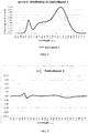
- FIG. 2 is a schematic diagram illustrating the relative spectral energy distribution of Embodiment 1.
- a luminescent peak for forming a first peak in the figure by energy of blue light emitted by the blue light LED chip is at a wavelength of 450nm, and a half-width FWHM is 21.8 ⁇ 5nm (21.8 is a measured value of one light source module, and because a slight divergence may be existed in actually measured values of the half-width for every light source module of the same batch in actual production, there will be a positive/negative range, and the values below follow the same pattern).
- the green fluorophor converts part of blue light emitted by the blue LED chip into green light.
- the red fluorophor (a nitride fluorescent powder for this embodiment) converts part of blue light emitted by the blue LED chip into red light, which forms a second peak in FIG. 2 .
- a luminescent peak is at a wavelength of 635nm, and a half-width FWHM is 83.2 ⁇ 5nm.
- a peak intensity of the first peak is about 47.6% of that of the second peak.
- the distribution of A( ⁇ ) in Embodiment 1 is illustrated in FIG.
- A( ⁇ ) A1( ⁇ )-A2( ⁇ ), and as can be seen from the figure, a value of A( ⁇ ) is in the range between -0.78 and 0.85.
- the light source module 104 is provided with: a blue LED chip with a peak wavelength of 455 ⁇ 5nm which is used as a blue light generating unit, a red fluorophor capable of converting part of blue light emitted by the blue light generating unit into red light which is used as a red light generating unit, and a green fluorophor capable of converting part of blue light emitted by the blue light generating unit into green light which is used as a green light generating unit.
- the blue light LED chip is used not only as the blue light generating unit, but also as an excitation light source for the red light generating unit and the green light generating unit.
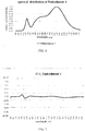
- FIG. 4 is a schematic diagram illustrating the relative spectral energy distribution of Embodiment 2.
- a luminescent peak for forming a first peak in the figure by energy of blue light emitted by the blue light LED chip is at a wavelength of 455nm, and a half-width FWHM is 22.3 ⁇ 5nm.
- the green fluorophor (Ga-YAG in aluminate system for this embodiment) converts part of blue light emitted by the blue LED chip into green light.
- the maximum value of a relative percentile difference between two neighboring spectral intensities with the same wavelength broadband is 0.09.
- the red fluorophor (a nitride fluorescent powder for this embodiment) converts part of blue light emitted by the blue LED chip into red light, which forms a second peak in FIG. 4 .
- a luminescent peak is at a wavelength of 635nm, and a half-width FWHM is 80.0 ⁇ 5nm.
- a peak intensity of the first peak is about 51.6% of that of the second peak.
- the light source module 104 is provided with: a blue LED chip with a peak wavelength of 450 ⁇ 5nm which is used as a blue light generating unit, a red fluorophor capable of converting part of blue light emitted by the blue light generating unit into red light which is used as a red light generating unit, and a green fluorophor capable of converting part of blue light emitted by the blue light generating unit into green light which is used as a green light generating unit.
- the blue light LED chip is used not only as the blue light generating unit, but also as an excitation light source for the red light generating unit and the green light generating unit.
- FIG. 6 is a schematic diagram illustrating the relative spectral energy distribution of Embodiment 3.
- a luminescent peak for forming a first peak in the figure by energy of blue light emitted by the blue light LED chip is at a wavelength of 450nm, and a half-width FWHM is 21.8 ⁇ 5nm.
- the green fluorophor (Lu-AG in aluminate system for this embodiment) converts part of blue light emitted by the blue LED chip into green light.
- the maximum value of a relative percentile difference between two neighboring spectral intensities with the same wavelength broadband is 0.08.
- the red fluorophor (a nitride fluorescent powder for this embodiment) converts part of blue light emitted by the blue LED chip into red light, which forms a second peak in FIG. 6 .
- a luminescent peak is at a wavelength of 635nm, and a half-width FWHM is 80.6 ⁇ 5nm.
- a peak intensity of the first peak is about 52.1% of that of the second peak.
- the light source module 104 is provided with: a blue LED chip with a peak wavelength of 450 ⁇ 5nm which is used as a blue light generating unit, a red fluorophor capable of converting part of blue light emitted by the blue light generating unit into red light which is used as a red light generating unit, and a green fluorophor capable of converting part of blue light emitted by the blue light generating unit into green light which is used as a green light generating unit.
- the blue light LED chip is used not only as the blue light generating unit, but also as an excitation light source for the red light generating unit and the green light generating unit.
- FIG. 8 is a schematic diagram illustrating the relative spectral energy distribution of Embodiment 4.
- a luminescent peak for forming a first peak in the figure by energy of blue light emitted by the blue light LED chip is at a wavelength of 450nm, and a half-width FWHM is 21.8 ⁇ 5nm.
- the green fluorophor (Ga-YAG in aluminate system for this embodiment) converts part of blue light emitted by the blue LED chip into green light.
- the maximum value of a relative percentile difference between two neighboring spectral intensities with the same wavelength broadband is 0.06.
- the red fluorophor (a nitride fluorescent powder for this embodiment) converts part of blue light emitted by the blue LED chip into red light, which forms a second peak in FIG. 8 .
- a luminescent peak is at a wavelength of 640nm, and a half-width FWHM is 96.4 ⁇ 5nm.
- a peak intensity of the first peak is about 50.3% of that of the second peak.
- the light source module 104 is provided with: a blue LED chip with a peak wavelength of 450 ⁇ 5nm which is used as a blue light generating unit, a red fluorophor capable of converting part of blue light emitted by the blue light generating unit into red light which is used as a red light generating unit, and a green fluorophor capable of converting part of blue light emitted by the blue light generating unit into green light which is used as a green light generating unit.
- the blue light LED chip is used not only as the blue light generating unit, but also as an excitation light source for the red light generating unit and the green light generating unit.
- FIG. 10 is a schematic diagram illustrating the relative spectral energy distribution of Embodiment 5.
- a luminescent peak for forming a first peak in the figure by energy of blue light emitted by the blue light LED chip is at a wavelength of 450nm, and a half-width FWHM is 21.8 ⁇ 5nm.
- the green fluorophor converts part of blue light emitted by the blue LED chip into green light. Within the range of 510nm to 580nm, by taking 5nm as a measuring interval, the maximum value of a relative percentile difference between two neighboring spectral intensities with the same wavelength broadband is 0.06.
- the red fluorophor (a nitride fluorescent powder in this embodiment) converts part of blue light emitted by the blue LED chip into red light, which forms a second peak in FIG. 10 .
- a luminescent peak is at a wavelength of 635nm, and a half-width FWHM is 80.0 ⁇ 5nm.
- a peak intensity of the first peak is about 52.1% of that of the second peak.
- the light color of the light source module of the present invention is standard white, and its Duv is in the range between -5 and 5.
Landscapes
- Engineering & Computer Science (AREA)
- General Engineering & Computer Science (AREA)
- Microelectronics & Electronic Packaging (AREA)
- Power Engineering (AREA)
- Physics & Mathematics (AREA)
- Optics & Photonics (AREA)
- Led Device Packages (AREA)
Abstract
Description
- The present invention relates to a light source module and an illuminating device including the light source module.
- With the arrival and development of the third lighting technology revolution, light-emitting diode (LED) lighting devices are widely used, and users have higher and higher requirements on a light quality thereof. For a long time, a research on the light quality has focused only on color rendering index (CRI) and cannot reach a deeper level.
- However, it has been found by the lighting industry that, a color rendering evaluation of LED light sources by CRI Ra is not consistent with a visual experience, and for environments with higher color saturation, CRI values usually are not consistent with the users' visual experience, either. It is also pointed out in a report of CIE (International Commission on Illumination) in 2007 that the CRI Ra is not suitable for evaluation of color rendering property of a LED light source. Organizations such as CIE and IES (Illuminating Engineering Society of North America) have proposed GAI, CQS and other methods for evaluating color rendering capacity of a light source, in succession, so as to supplement the deficiency of CRI. IES officially released a new method for evaluating the color rendering capacity of a light source, i.e., IES TM-30-15 IES Method for Evaluating Light Source Color Rendition, on May 18, 2015. Chip packaging manufacturers and chip application manufacturers have also offered products with higher GAI index, higher CQS index, or better TM30-15 index, in addition to the CRI index, one after another. However, a relationship between a specific index and a visual representation of the product still needs to be verified.
- An objective of the present invention is to seek for a LED light source with higher vividness, according to indexes such as CRI, GAI, CQS and TM30-15, so as to solve the above problem.
- In order to achieve the objective above, the technical solution as adopted by the present invention is to provide a light source module, including:
- a blue light generating unit configured to emit blue light;
- a green light generating unit configured to emit green light; and
- a red light generating unit configured to emit red light, wherein
- for the blue light, a peak wavelength is within the range of 430nm to 470nm, and a half-width of an emission spectrum is within the range of 15nm to 35nm;
- for the red light, a peak wavelength is within the range of 620nm to 660nm, and a half-width of an emission spectrum is within the range of 70nm to 105nm; wherein a peak intensity of the blue light is 40% to 60% of a peak intensity of the red light;
- for the green light, within a spectrum range of 510nm to 580nm, by taking 5nm as a measuring interval, a relative difference of neighboring spectral intensities within a wavelength width of 5nm is less than 15%; and
- irradiation light emitted by the light source module satisfies such a condition in the CIE1931 color coordinate system that, a horizontal coordinate X is within the range of 0.410 to 0.450, and a longitudinal coordinate Y is within the range of 0.375 to 0.415.
- Further, light emitted by the light source module further satisfies the condition that: given a same wavelength, a difference A(λ) between a change rate A1(λ) of spectral intensities for neighboring wavelengths of a luminescent spectrum of the light source module, and a change rate A2(λ) of spectral intensities for neighboring wavelengths of a heat dissipation spectrum of Planck blackbody radiation with a color temperature as same as that of the light source module is within the range of [-3.0, 3.0].
- Further, the A(λ) is within the range of [-1.5, 1.5].
- Further, the half-width of the emission spectrum of the red light is within the range of 70nm to 85nm or the range of 95nm to 105nm.
- Further, the blue light generating unit is a blue LED chip.
- Further, the green light generating unit contains a green fluorophor which absorbs light emitted by the blue light generating unit and emits green light through wavelength conversion.
- Further, the red light generating unit contains a red fluorophor which absorbs light emitted by the blue light generating unit and emits red light through wavelength conversion.
- Further, the blue light generating unit, the green light generating unit and the red light generating unit are integrally packaged, wherein the blue light generating unit is a blue LED, the green light generating unit is a green fluorophor which absorbs light emitted by the blue light generating unit and emits green light through wavelength conversion, and the red light generating unit is a red fluorophor which absorbs light emitted by the blue light generating unit and emits red light through wavelength conversion.
- Further, the green fluorophor is of aluminate system or silicate system or nitride system or oxynitride system or a combination of any two thereof.
- Further, the red fluorophor is of nitride system or silicate system or a combination thereof.
- Further, the horizontal coordinate X is within the range of 0.420 to 0.440, and the longitudinal coordinate Y is within the range of 0.385 to 0.405.
- Further, the horizontal coordinate X is within the range of 0.425 to 0.435, and the longitudinal coordinate Y is within the range of 0.390 to 0.400.
- Further, a color temperature of the light emitted by the light source module is within the range of 2500K to 3600K.
- Further, a color rendering parameter CRI of the light emitted by the light source module is greater than 90.
- Further, a color rendering index Rf of the light emitted by the light source module is greater than 90.
- Further, a color rendering index R9 of the light emitted by the light source module is greater than 70.
- Further, a gamut index Rg of the light emitted by the light source module is greater than 100.
- The present invention further provides an illuminating device, including:
- the light source module described above; and
- a power supply module connected to the light source module and configured to provide the light source module with a working power.
- Further, the illuminating device further includes a controller, the controller is connected to the light source module and configured to adjust the irradiation light emitted by the light source module
- The light source module provided by the present invention has a specific spectral distribution, in which not only an evaluation of illuminating effect under color theory but also an influence of a spectrum on an actual illuminating effect is considered, and meanwhile an impact of a luminous material on the spectrum is also taken into account. Thus, a light source highly preferred by illuminated objects with high vividness, high color rendering index and high color gamut index can be obtained, and the light source can achieve an effect similar to a ceramic metal halide lamp.
- The drawings described herein are intended to provide a further understanding of the present invention and constitute one part thereof. The illustrative embodiments of the present invention and the description thereof are used for explaining the present invention and do not constitute any inappropriate limitation of the present invention.
-
FIG. 1 is a structurally schematic diagram illustrating an illuminating device of the present invention; -
FIG. 2 is a schematic diagram illustrating the relative spectral energy distribution ofEmbodiment 1 of the present invention; -
FIG. 3 is a schematic diagram illustrating the distribution of A (λ) inEmbodiment 1 of the present invention; -
FIG. 4 is a schematic diagram illustrating the relative spectral energy distribution ofEmbodiment 2 of the present invention -
FIG. 5 is a schematic diagram illustrating the distribution of A (λ) inEmbodiment 2 of the present invention; -
FIG. 6 is a schematic diagram illustrating the relative spectral energy distribution ofEmbodiment 3 of the present invention -
FIG. 7 is a schematic diagram illustrating the distribution of A (λ) inEmbodiment 3 of the present invention; -
FIG. 8 is a schematic diagram illustrating the relative spectral energy distribution ofEmbodiment 4 of the present invention -
FIG. 9 is a schematic diagram illustrating the distribution of A (λ) inEmbodiment 4 of the present invention; -
FIG. 10 is a schematic diagram illustrating the relative spectral energy distribution ofEmbodiment 5 of the present invention -
FIG. 11 is a schematic diagram illustrating the distribution of A (λ) inEmbodiment 5 of the present invention; -
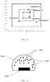
FIG.12 is a schematic diagram illustrating CIE1931 color coordinate ofEmbodiments 1 to 5 of the present invention; and -
FIG.13 is a structurally schematic diagram illustrating a light source module according to the present invention. - A light source module and an illuminating device provided by the present invention will be described further below in connection with accompanying drawings and particular embodiments.
- The light source module provided by the present invention is a warm white light source with a color temperature in the range from 2500K to 3600K, and can be applied in a
lighting luminaire 101 illustrated inFIG. 1 for daily lighting. Thelighting luminaire 101 includes a power driver (not illustrated), acontroller 102, aheat dissipation device 103, alighting module 104 and alampshade 105, etc. The controller may be configured to adjust a light color and a light intensity of thelighting module 104, and thelampshade 105 may be replaced by other optical elements in other embodiments, such as a lens, a diffusion element, a photoconductor or the like, in accordance with the design of the luminaire. The heat dissipation device may not be included in the lighting luminaire. Thelight source module 104 includes a blue light generating unit for outputting a blue light component, a green light generating unit for outputting a yellowish-green light component and a red light generating unit for outputting a red light component. - These light generating units for different colors of light in the
light source module 104 may be LED chips or fluorescent materials capable of converting a wavelength of light, or a combination of LED chips and fluorescent materials. Depending on the difference in color of the emitted light, fluorescent powders of different systems may be adopted as the fluorescent material. For the blue light generating unit, a monochromatic LED chip may be adopted, and the monochromatic LED chip used herein refers to a LED chip which gives out light by directly exciting a semiconductor material and has no fluorophor. In addition, it is also possible for the blue light generating unit to adopt a mode of a LED chip in cooperation with a fluorophor, that is, the blue light generating unit contains a blue fluorophor which absorbs light emitted by a semiconductor luminous element (LED chip) and emits blue light through wavelength conversion; and the semiconductor luminous element used herein may be a monochromatic LED chip which emits ultraviolet light. The red light generating unit is similar to the blue light generating unit, and may adopt a monochromatic LED chip; moreover, in a preferred embodiment, the red light generating unit contains a red fluorophor which absorbs light emitted by a semiconductor luminous element and emits red light through wavelength conversion. And the green light generating unit includes a green fluorophor which absorbs light emitted by a semiconductor luminous element and emits green light through wavelength conversion. The type of the green fluorophor includes aluminate system such as YAG, Ga-YAG, Lu-AG, TbAG and so on, silicate system, nitride system, and nitrogen oxide system. The green light generating unit may be excited by a single type of fluorophor to produce green light, and may also be excited by a combination of two types of fluorphors or more, or even a combination of fluorophors with a variety of peak wavelengths. When it's the case of a combination of several types of fluorophors, these fluorophors are not confined in one element or component; for example, they may be different green fluorophors in two white LEDs, and a spectral intensity in the range from 510nm to 580nm as required can be obtained by superimposing spectrums produced by these fluorophors. This combination of fluorophors is not limited to be used in the green light generating unit, and when the blue light generating unit and the red light generating unit contain fluorophors, they may also use fluorophors with various compositions, and these fluorophors may be distributed in different elements or components. It should be explained that, the "red light generating unit" and the "green light generating unit" used herein are merely an expression for describing the present invention, and a red fluorophor with a wider emission bandwidth always has part of its energy in a green light domain; in this case, it should be understood that, the red fluorophor partly realizes a function of the red light generating unit and partly contributes to green light emission, that is, the green light generating unit is composed of a green fluorophor and a red fluorophor. - The design scheme of the
light source module 104 is finally determined by designing a specific proportion for different generating units, in combination with data of visual experiments. As illustrated in FIG.15, the bluelight generating unit 1041 is a blue light LED, the greenlight generating unit 1042 is a green fluorescent powder, the redlight generating unit 1043 is a red fluorescent powder, and thelight source module 104 is a white light LED chip; the white light LED chip is packaged and forms a white spectrum with a color temperature in the range between 2500K and 3600K, and both the color rendering parameters CRI, R9, Rf and the color gamut index Rg and the like of the spectrum have higher values. Corresponding to the blue light generating unit, the red light generating unit and the green light generating unit, a spectral distribution of thelight source module 104 has relatively obvious, two spectral emission peaks. For the first emission peak, its wavelength resides between 430nm and 470nm, it is generated by the blue light generating unit, and a half-width of its emission spectrum is in the range of 15nm to 35nm. A luminous zone formed by green light generated by the green light generating unit is distributed over a range of 510nm to 580nm, and the spectral distribution of green light is gentle. Taking 5nm as a measuring interval, a relative difference between neighboring spectral intensities within a wavelength width of 5nm is less than 15%. For the second emission peak, its wavelength resides between 620nm and 660nm, it is produced by red fluorescent powders excited by blue light, and a spectral intensity of the second peak is the maximum value in the whole spectrum. The peak intensity of blue light, that is, the first peak, is 40% to 60% of the peak intensity of red light, that is, the second peak. A half-width of an emission spectrum of red fluorescent powders is in the range of 70nm to 105nm, and in a specific embodiment, the half-width of most of the red fluorophors in the present invention falls within following two ranges: 70nm to 85nm, and 95nm to 105nm. As a result, values in these two ranges are more preferred. - As a feature of the present invention, under the same wavelength, a change rate of spectral intensity for neighboring wavelengths of a luminescent spectrum of the
light source module 104 is indicated by A1(λ), and a change rate of spectral intensity for neighboring wavelengths of a heat radiation spectrum of Planck blackbody radiation having the same color temperature with thelight source module 104 is indicted by A2(λ). A difference A(λ) between A1(λ) and A2(λ) falls within the region of [-3.0, 3.0], that is, -3.0≤A1(λ)-A2(λ)≤3.0, and in a more preferred embodiment, -1.5≤A1(λ)-A2(λ)≤1.5. - The term "neighboring" as used herein takes 5nm as a computation interval, that is, when the change rate of spectral intensity for neighboring wavelengths is calculated, an interval of 5nm is taken into account, and particular operational formulas for A1(λ) and A2(λ) are as follows:


- The heat radiation spectrum is calculated according to the Planck blackbody radiation formula, and the computational formulas are as follows:


- A color coordinate scope of the light color of the
light source module 104 is that, x is in the range between 0.410 and 0.450, and y is in the range between 0.375 and 0.415 (x=0.410∼0.450, y=0.375∼0.415); a preferred color coordinate scope is that, x is in the range between 0.420 and 0.440, and y is in the range between 0.385 and 0.405 (x=0.420∼0.440, y=0.385∼0.405); and the most preferred scope is that, x is in the range between 0.425 and 0.435, and y is in the range between 0.390 and 0.400 (x=0.425∼0.435, y=0.390∼0.400). The color rendering parameters CRI, Rf of this spectrum each are no less than 90.0; R9 is no less than 70.0; and the gamut index Rg is no less than 100.0. - Several preferred embodiments of the
light source module 104 will be introduced below. - The
light source module 104 is provided with: a blue LED chip with a peak wavelength of 450 ±5nm which is used as a blue light generating unit, a red fluorophor capable of converting part of blue light emitted by the blue light generating unit into red light which is used as a red light generating unit, and a green fluorophor capable of converting part of blue light emitted by the blue light generating unit into green light which is used as a green light generating unit. In the present embodiment, the blue light LED chip is used not only as the blue light generating unit, but also as an excitation light source for the red light generating unit and the green light generating unit.FIG. 2 is a schematic diagram illustrating the relative spectral energy distribution ofEmbodiment 1. A luminescent peak for forming a first peak in the figure by energy of blue light emitted by the blue light LED chip is at a wavelength of 450nm, and a half-width FWHM is 21.8 ±5nm (21.8 is a measured value of one light source module, and because a slight divergence may be existed in actually measured values of the half-width for every light source module of the same batch in actual production, there will be a positive/negative range, and the values below follow the same pattern). The green fluorophor converts part of blue light emitted by the blue LED chip into green light. Within the range of 510nm to 580nm, by taking 5nm as a measuring interval, the maximum value of a relative percentile difference between two neighboring spectral intensities with the same wavelength broadband is 0.11. The red fluorophor (a nitride fluorescent powder for this embodiment) converts part of blue light emitted by the blue LED chip into red light, which forms a second peak inFIG. 2 . For the second peak, a luminescent peak is at a wavelength of 635nm, and a half-width FWHM is 83.2±5nm. A peak intensity of the first peak is about 47.6% of that of the second peak. The distribution of A(λ) inEmbodiment 1 is illustrated inFIG. 3 , wherein A(λ)=A1(λ)-A2(λ), and as can be seen from the figure, a value of A(λ) is in the range between -0.78 and 0.85. A color coordinate ofEmbodiment 1 is x=0.4337 and y=0.3919 (x=0.4337, y=0. 0.3919), a color temperature is 2964K, color rendering indexes CRI=95.6, R9=95.8, Rf=93.4, and a gamut index Rg=105.6. - The
light source module 104 is provided with: a blue LED chip with a peak wavelength of 455 ±5nm which is used as a blue light generating unit, a red fluorophor capable of converting part of blue light emitted by the blue light generating unit into red light which is used as a red light generating unit, and a green fluorophor capable of converting part of blue light emitted by the blue light generating unit into green light which is used as a green light generating unit. In the present embodiment, the blue light LED chip is used not only as the blue light generating unit, but also as an excitation light source for the red light generating unit and the green light generating unit.FIG. 4 is a schematic diagram illustrating the relative spectral energy distribution ofEmbodiment 2. A luminescent peak for forming a first peak in the figure by energy of blue light emitted by the blue light LED chip is at a wavelength of 455nm, and a half-width FWHM is 22.3±5nm. The green fluorophor (Ga-YAG in aluminate system for this embodiment) converts part of blue light emitted by the blue LED chip into green light. Within the range of 510nm to 580nm, by taking 5nm as a measuring interval, the maximum value of a relative percentile difference between two neighboring spectral intensities with the same wavelength broadband is 0.09. The red fluorophor (a nitride fluorescent powder for this embodiment) converts part of blue light emitted by the blue LED chip into red light, which forms a second peak inFIG. 4 . For the second peak, a luminescent peak is at a wavelength of 635nm, and a half-width FWHM is 80.0±5nm. A peak intensity of the first peak is about 51.6% of that of the second peak. The distribution of A(λ) inEmbodiment 2 is illustrated inFIG. 5 , wherein A(λ)=A1(λ)-A2(λ), and as can be seen from the figure, a value of A(λ) is in the range between -1.16 and 1.40. A color coordinate ofEmbodiment 2 is x=0.4438 and y=0.3835 (x=0.4438, y=0.3835), a color temperature is 2728K, color rendering indexes CRI=90.3, R9=80.9, Rf=91.6, and a gamut index Rg=107.2. - The
light source module 104 is provided with: a blue LED chip with a peak wavelength of 450 ±5nm which is used as a blue light generating unit, a red fluorophor capable of converting part of blue light emitted by the blue light generating unit into red light which is used as a red light generating unit, and a green fluorophor capable of converting part of blue light emitted by the blue light generating unit into green light which is used as a green light generating unit. In the present embodiment, the blue light LED chip is used not only as the blue light generating unit, but also as an excitation light source for the red light generating unit and the green light generating unit.FIG. 6 is a schematic diagram illustrating the relative spectral energy distribution ofEmbodiment 3. A luminescent peak for forming a first peak in the figure by energy of blue light emitted by the blue light LED chip is at a wavelength of 450nm, and a half-width FWHM is 21.8±5nm. The green fluorophor (Lu-AG in aluminate system for this embodiment) converts part of blue light emitted by the blue LED chip into green light. Within the range of 510nm to 580nm, by taking 5nm as a measuring interval, the maximum value of a relative percentile difference between two neighboring spectral intensities with the same wavelength broadband is 0.08. The red fluorophor (a nitride fluorescent powder for this embodiment) converts part of blue light emitted by the blue LED chip into red light, which forms a second peak inFIG. 6 . For the second peak, a luminescent peak is at a wavelength of 635nm, and a half-width FWHM is 80.6±5nm. A peak intensity of the first peak is about 52.1% of that of the second peak. The distribution of A(λ) inEmbodiment 3 is illustrated inFIG. 7 , wherein A(λ)=A1(λ)-A2(λ), and as can be seen from the figure, a value of A(λ) is in the range between -1.11 and 1.15. A color coordinate ofEmbodiment 3 is x=0.4348 and y=0.4014 (x=0.4348, y=0.4014), a color temperature is 3014K, color rendering indexes CRI=96.6, R9=97.5, Rf=95.5, and a gamut index Rg=103.0. - The
light source module 104 is provided with: a blue LED chip with a peak wavelength of 450 ±5nm which is used as a blue light generating unit, a red fluorophor capable of converting part of blue light emitted by the blue light generating unit into red light which is used as a red light generating unit, and a green fluorophor capable of converting part of blue light emitted by the blue light generating unit into green light which is used as a green light generating unit. In the present embodiment, the blue light LED chip is used not only as the blue light generating unit, but also as an excitation light source for the red light generating unit and the green light generating unit.FIG. 8 is a schematic diagram illustrating the relative spectral energy distribution ofEmbodiment 4. A luminescent peak for forming a first peak in the figure by energy of blue light emitted by the blue light LED chip is at a wavelength of 450nm, and a half-width FWHM is 21.8±5nm. The green fluorophor (Ga-YAG in aluminate system for this embodiment) converts part of blue light emitted by the blue LED chip into green light. Within the range of 510nm to 580nm, by taking 5nm as a measuring interval, the maximum value of a relative percentile difference between two neighboring spectral intensities with the same wavelength broadband is 0.06. The red fluorophor (a nitride fluorescent powder for this embodiment) converts part of blue light emitted by the blue LED chip into red light, which forms a second peak inFIG. 8 . For the second peak, a luminescent peak is at a wavelength of 640nm, and a half-width FWHM is 96.4±5nm. A peak intensity of the first peak is about 50.3% of that of the second peak. The distribution of A(λ) inEmbodiment 4 is illustrated inFIG. 9 , wherein A(λ)=A1(λ)-A2(λ), and as can be seen from the figure, a value of A(λ) is in the range between -1.06 and 1.10. A color coordinate ofEmbodiment 4 is x=0.4325 and y=0.4045 (x=0.4325, y=0.4045), a color temperature is 3080K, color rendering indexes CRI=97.3, R9=97.0, Rf=95.5, and a gamut index Rg=103.0. - The
light source module 104 is provided with: a blue LED chip with a peak wavelength of 450 ±5nm which is used as a blue light generating unit, a red fluorophor capable of converting part of blue light emitted by the blue light generating unit into red light which is used as a red light generating unit, and a green fluorophor capable of converting part of blue light emitted by the blue light generating unit into green light which is used as a green light generating unit. In the present embodiment, the blue light LED chip is used not only as the blue light generating unit, but also as an excitation light source for the red light generating unit and the green light generating unit.FIG. 10 is a schematic diagram illustrating the relative spectral energy distribution ofEmbodiment 5. A luminescent peak for forming a first peak in the figure by energy of blue light emitted by the blue light LED chip is at a wavelength of 450nm, and a half-width FWHM is 21.8±5nm. The green fluorophor converts part of blue light emitted by the blue LED chip into green light. Within the range of 510nm to 580nm, by taking 5nm as a measuring interval, the maximum value of a relative percentile difference between two neighboring spectral intensities with the same wavelength broadband is 0.06. The red fluorophor (a nitride fluorescent powder in this embodiment) converts part of blue light emitted by the blue LED chip into red light, which forms a second peak inFIG. 10 . For the second peak, a luminescent peak is at a wavelength of 635nm, and a half-width FWHM is 80.0 ±5nm. A peak intensity of the first peak is about 52.1% of that of the second peak. The distribution of A(λ) inEmbodiment 5 is illustrated inFIG. 11 , wherein A(λ)=A1(λ)-A2(λ), and as can be seen from the figure, a value of A(λ) is in the range between -0.71 and 0.93. A color coordinate ofEmbodiment 5 is x=0.4194 and y=0.3840, a color temperature is 3163K, color rendering indexes CRI=92.4, R9=78.9, Rf=93.8, and a gamut index Rg=104.8. - The light color of the light source module of the present invention is standard white, and its Duv is in the range between -5 and 5.
FIG. 12 illustrates the light color coordinates of thelight source modules 104 inEmbodiments 1 to 5 in the CIE1931 color coordinate system, and it can be found that, these points all fall within such a coordinate scope that x is in the range between 0.410 and 0.450 and y is in the range between 0.375 and 0.415 (x=0.410∼0.450, y=0.375∼0.415). Further, it's found that,Embodiment 1,Embodiment 3 andEmbodiment 4 achieve better effects, and the color coordinate scope of these three embodiments is that, x is in the range between 0.420 and 0.440, and y is in the range between 0.385 and 0.405 (x=0.420∼0.440,y=0.385∼0.405). Moreover, the best scope is that, x is in the range between 0.425 and 0.435, and y is in the range between 0.390 and 0.400 (x=0.425∼0.435, y=0.390∼0.400);Embodiment 1 is just within this best scope. - The objectives, the technical solutions and the beneficial advantages of the present invention have been described in details with reference to the above particular embodiments. It should be understood that, the above are only specific implementations of the present disclosure, and the protection scope of the present disclosure is not limited thereto. Any modifications, substitutions and improvements that easily occur to those skilled in the art within the spirit and principle of the present invention should be fallen within the protection scope of the present invention.
Claims (19)
- A light source module, comprising
a blue light generating unit configured to emit blue light;
a green light generating unit configured to emit green light; and
a red light generating unit configured to emit red light, wherein
for the blue light, a peak wavelength is within the range of 430nm to 470nm, and a half-width of an emission spectrum is within the range of 15nm to 35nm;
for the red light, a peak wavelength is within the range of 620nm to 660nm, and a half-width of an emission spectrum is within the range of 70nm to 105nm; wherein a peak intensity of the blue light is 40% to 60% of a peak intensity of the red light;
for the green light, within a spectrum range of 510nm to 580nm, by taking 5nm as a measuring interval, a relative difference of neighboring spectral intensities within a wavelength width of 5nm is less than 15%; and
irradiation light emitted by the light source module satisfies such a condition in the CIE1931 color coordinate system that, a horizontal coordinate X is within the range of 0.410 to 0.450, and a longitudinal coordinate Y is within the range of 0.375 to 0.415. - The light source module according to claim 1, wherein light emitted by the light source module further satisfies the condition that: given a same wavelength, a difference A(λ) between a change rate A1(λ) of spectral intensities for neighboring wavelengths of a luminescent spectrum of the light source module, and a change rate A2(λ) of spectral intensities for neighboring wavelengths of a heat dissipation spectrum of Planck blackbody radiation with a color temperature as same as that of the light source module is within the range of [-3.0, 3.0].
- The light source module according to claim 2, wherein the A(λ) is within the range of [-1.5, 1.5].
- The light source module according to claim 2, wherein the half-width of the emission spectrum of the red light is within the range of 70nm to 85nm or the range of 95nm to 105nm.
- The light source module according to claim 2, wherein the blue light generating unit is a blue LED chip.
- The light source module according to claim 2, wherein the green light generating unit contains a green fluorophor which absorbs light emitted by the blue light generating unit and emits green light through wavelength conversion.
- The light source module according to claim 2, wherein the red light generating unit contains a red fluorophor which absorbs light emitted by the blue light generating unit and emits red light through wavelength conversion.
- The light source module according to claim 2, wherein the blue light generating unit, the green light generating unit and the red light generating unit are integrally packaged, wherein
the blue light generating unit is a blue LED,
the green light generating unit is a green fluorophor which absorbs light emitted by the blue light generating unit and emits green light through wavelength conversion, and
the red light generating unit is a red fluorophor which absorbs light emitted by the blue light generating unit and emits red light through wavelength conversion. - The light source module according to claim 6 or 8, wherein the green fluorophor is of aluminate system or silicate system or nitride system or oxynitride system or a combination of any two thereof.
- The light source module according to claim 7 or 8, wherein the red fluorophor is of nitride system or silicate system or a combination thereof.
- The light source module according to claim 1, wherein, the horizontal coordinate X is within the range of 0.420 to 0.440, and the longitudinal coordinate Y is within the range of 0.385 to 0.405.
- The light source module according to claim 11, wherein the horizontal coordinate X is within the range of 0.425 to 0.435, and the longitudinal coordinate Y is within the range of 0.390 to 0.400.
- The light source module according to claim 2, wherein a color temperature of the light emitted by the light source module is within the range of 2500K to 3600K.
- The light source module according to claim 2, wherein a color rendering parameter CRI of the light emitted by the light source module is greater than 90.
- The light source module according to claim 2, wherein a color rendering index Rf of the light emitted by the light source module is greater than 90.
- The light source module according to claim 2, wherein a color rendering index R9 of the light emitted by the light source module is greater than 70.
- The light source module according to claim 2, wherein a gamut index Rg of the light emitted by the light source module is greater than 100.
- An illuminating device, comprising
the light source module according to any one of claims 1 to 17; and
a power supply module connected to the light source module and configured to provide the light source module with a working power. - The illuminating device according to claim 18, further comprising a controller, the controller is connected to the light source module and configured to adjust the irradiation light emitted by the light source module.
Applications Claiming Priority (3)
| Application Number | Priority Date | Filing Date | Title |
|---|---|---|---|
| CN201710222531.9A CN106931332A (en) | 2017-04-07 | 2017-04-07 | A kind of light source module and the lighting device including the light source module |
| CN201720356384.XU CN206708776U (en) | 2017-04-07 | 2017-04-07 | A kind of light source module group and the lighting device including the light source module group |
| PCT/CN2018/081969 WO2018184575A1 (en) | 2017-04-07 | 2018-04-04 | Light source module, and illumination device comprising light source module |
Publications (3)
| Publication Number | Publication Date |
|---|---|
| EP3575670A1 true EP3575670A1 (en) | 2019-12-04 |
| EP3575670A4 EP3575670A4 (en) | 2020-09-09 |
| EP3575670B1 EP3575670B1 (en) | 2022-08-10 |
Family
ID=63712391
Family Applications (1)
| Application Number | Title | Priority Date | Filing Date |
|---|---|---|---|
| EP18781536.0A Active EP3575670B1 (en) | 2017-04-07 | 2018-04-04 | Light source module, and illumination device comprising light source module |
Country Status (3)
| Country | Link |
|---|---|
| US (1) | US20200044123A1 (en) |
| EP (1) | EP3575670B1 (en) |
| WO (1) | WO2018184575A1 (en) |
Families Citing this family (2)
| Publication number | Priority date | Publication date | Assignee | Title |
|---|---|---|---|---|
| CN118242570A (en) * | 2024-03-20 | 2024-06-25 | 漳州立达信光电子科技有限公司 | A narrow-band RGBY light source module and lighting device with high color rendering index |
| CN118610347B (en) * | 2024-06-14 | 2024-12-13 | 东莞市立德达光电科技有限公司 | High-color quality parameter spectrum LED light source and preparation method thereof |
Family Cites Families (13)
| Publication number | Priority date | Publication date | Assignee | Title |
|---|---|---|---|---|
| WO2011024818A1 (en) * | 2009-08-26 | 2011-03-03 | 三菱化学株式会社 | Semiconductor white light-emitting device |
| US8643038B2 (en) * | 2010-03-09 | 2014-02-04 | Cree, Inc. | Warm white LEDs having high color rendering index values and related luminophoric mediums |
| JP2012060097A (en) * | 2010-06-25 | 2012-03-22 | Mitsubishi Chemicals Corp | White semiconductor light-emitting device |
| WO2012046288A1 (en) * | 2010-10-04 | 2012-04-12 | 電気化学工業株式会社 | β-SIALON PHOSPHOR, METHOD FOR PRODUCING SAME, AND USE OF SAME |
| JP2013201274A (en) * | 2012-03-23 | 2013-10-03 | Toshiba Lighting & Technology Corp | Luminaire |
| CN104303298B (en) * | 2012-04-06 | 2018-01-19 | 飞利浦照明控股有限公司 | white light emitting module |
| US9406849B2 (en) * | 2012-08-10 | 2016-08-02 | Koninklijke Philips N.V. | Phosphor converted light emitting diode, a lamp and a luminaire |
| US10208943B2 (en) * | 2013-10-28 | 2019-02-19 | GE Lighting Solutions, LLC | Lamps for enhanced optical brightening and color preference |
| CN105737090A (en) * | 2016-02-03 | 2016-07-06 | 欧普照明股份有限公司 | Light source module and lighting device |
| CN105737091B (en) * | 2016-02-03 | 2019-09-27 | 欧普照明股份有限公司 | Light source module and lighting device |
| CN205640712U (en) * | 2016-02-03 | 2016-10-12 | 欧普照明股份有限公司 | Light source module and lighting device |
| CN106931332A (en) * | 2017-04-07 | 2017-07-07 | 欧普照明股份有限公司 | A kind of light source module and the lighting device including the light source module |
| CN206708776U (en) * | 2017-04-07 | 2017-12-05 | 欧普照明股份有限公司 | A kind of light source module group and the lighting device including the light source module group |
-
2018
- 2018-04-04 WO PCT/CN2018/081969 patent/WO2018184575A1/en not_active Ceased
- 2018-04-04 EP EP18781536.0A patent/EP3575670B1/en active Active
-
2019
- 2019-10-07 US US16/594,808 patent/US20200044123A1/en not_active Abandoned
Also Published As
| Publication number | Publication date |
|---|---|
| EP3575670A4 (en) | 2020-09-09 |
| EP3575670B1 (en) | 2022-08-10 |
| WO2018184575A1 (en) | 2018-10-11 |
| US20200044123A1 (en) | 2020-02-06 |
Similar Documents
| Publication | Publication Date | Title |
|---|---|---|
| RU2444813C2 (en) | Light-emitting diode module, light-emitting diode source and light-emitting diode lamp for energy-efficient generation of white light | |
| EP3064039B1 (en) | Lamps for enhanced optical brightening and color preference | |
| EP3346512B1 (en) | Semiconductor light-emitting device, exhibit-irradiating illumination device, meat-irradiating illumination device, vegetable-irradiating illumination device, fresh fish-irradiating illumination device, general-purpose illumination device, and semiconductor light-emitting system | |
| JP2025063100A (en) | Full spectrum white light emitting device | |
| US10701775B2 (en) | Methods for generating melatonin-response-tuned white light with high color rendering | |
| CN112135643A (en) | Multiple light emitters that inactivate microorganisms | |
| CN204387966U (en) | A kind of lighting device and comprise the light fixture of this lighting device | |
| CN114270511A (en) | Full spectrum white light emitting device | |
| EP4151053B1 (en) | Melanopic light system with high cri using cyan direct emitters | |
| CN106931332A (en) | A kind of light source module and the lighting device including the light source module | |
| CN108350354A (en) | Improved white illumination equipment for being sold illumination | |
| WO2021204934A1 (en) | Melanopic light system using cyan pumped white leds | |
| CN206708776U (en) | A kind of light source module group and the lighting device including the light source module group | |
| WO2021007123A1 (en) | Full spectrum white light emitting devices | |
| EP3575670B1 (en) | Light source module, and illumination device comprising light source module | |
| CN105823009B (en) | A kind of lighting device illuminated for fresh meat and the light fixture including the lighting device | |
| US10462870B2 (en) | Light source circuit and illumination apparatus | |
| JP2016517537A (en) | Dimmable light emitting device | |
| CN207247110U (en) | A kind of light source module group and the lighting device including the light source module group | |
| US10465872B2 (en) | Light source module and illuminating device | |
| Le Thi Thuy My et al. | Yellow-green emitting CaGa2S4: Eu2+ phosphor: an application for enhancing the luminous flux of the white light emitting diodes | |
| US11211530B2 (en) | Light source and illumination device including the light source | |
| Huu et al. | Application of green-emitting Sr 3 WO 6: U phosphor to enhance lumen efficiency of WLEDs | |
| Bailey et al. | Achieving high CRI from warm to super white |
Legal Events
| Date | Code | Title | Description |
|---|---|---|---|
| STAA | Information on the status of an ep patent application or granted ep patent |
Free format text: STATUS: THE INTERNATIONAL PUBLICATION HAS BEEN MADE |
|
| PUAI | Public reference made under article 153(3) epc to a published international application that has entered the european phase |
Free format text: ORIGINAL CODE: 0009012 |
|
| STAA | Information on the status of an ep patent application or granted ep patent |
Free format text: STATUS: REQUEST FOR EXAMINATION WAS MADE |
|
| 17P | Request for examination filed |
Effective date: 20190828 |
|
| AK | Designated contracting states |
Kind code of ref document: A1 Designated state(s): AL AT BE BG CH CY CZ DE DK EE ES FI FR GB GR HR HU IE IS IT LI LT LU LV MC MK MT NL NO PL PT RO RS SE SI SK SM TR |
|
| AX | Request for extension of the european patent |
Extension state: BA ME |
|
| DAV | Request for validation of the european patent (deleted) | ||
| DAX | Request for extension of the european patent (deleted) | ||
| A4 | Supplementary search report drawn up and despatched |
Effective date: 20200812 |
|
| RIC1 | Information provided on ipc code assigned before grant |
Ipc: F21V 23/00 20150101ALI20200806BHEP Ipc: F21K 9/64 20160101AFI20200806BHEP Ipc: H01L 33/50 20100101ALI20200806BHEP Ipc: F21Y 115/10 20160101ALI20200806BHEP Ipc: F21K 9/00 20160101ALI20200806BHEP |
|
| STAA | Information on the status of an ep patent application or granted ep patent |
Free format text: STATUS: EXAMINATION IS IN PROGRESS |
|
| 17Q | First examination report despatched |
Effective date: 20210312 |
|
| GRAP | Despatch of communication of intention to grant a patent |
Free format text: ORIGINAL CODE: EPIDOSNIGR1 |
|
| STAA | Information on the status of an ep patent application or granted ep patent |
Free format text: STATUS: GRANT OF PATENT IS INTENDED |
|
| INTG | Intention to grant announced |
Effective date: 20220426 |
|
| RIN1 | Information on inventor provided before grant (corrected) |
Inventor name: QIANG, JIE Inventor name: ZHOU, ZHIXIAN |
|
| GRAS | Grant fee paid |
Free format text: ORIGINAL CODE: EPIDOSNIGR3 |
|
| GRAA | (expected) grant |
Free format text: ORIGINAL CODE: 0009210 |
|
| STAA | Information on the status of an ep patent application or granted ep patent |
Free format text: STATUS: THE PATENT HAS BEEN GRANTED |
|
| AK | Designated contracting states |
Kind code of ref document: B1 Designated state(s): AL AT BE BG CH CY CZ DE DK EE ES FI FR GB GR HR HU IE IS IT LI LT LU LV MC MK MT NL NO PL PT RO RS SE SI SK SM TR |
|
| REG | Reference to a national code |
Ref country code: AT Ref legal event code: REF Ref document number: 1510792 Country of ref document: AT Kind code of ref document: T Effective date: 20220815 Ref country code: CH Ref legal event code: EP |
|
| REG | Reference to a national code |
Ref country code: DE Ref legal event code: R096 Ref document number: 602018039125 Country of ref document: DE |
|
| REG | Reference to a national code |
Ref country code: IE Ref legal event code: FG4D |
|
| REG | Reference to a national code |
Ref country code: NL Ref legal event code: FP |
|
| REG | Reference to a national code |
Ref country code: LT Ref legal event code: MG9D |
|
| PG25 | Lapsed in a contracting state [announced via postgrant information from national office to epo] |
Ref country code: SE Free format text: LAPSE BECAUSE OF FAILURE TO SUBMIT A TRANSLATION OF THE DESCRIPTION OR TO PAY THE FEE WITHIN THE PRESCRIBED TIME-LIMIT Effective date: 20220810 Ref country code: RS Free format text: LAPSE BECAUSE OF FAILURE TO SUBMIT A TRANSLATION OF THE DESCRIPTION OR TO PAY THE FEE WITHIN THE PRESCRIBED TIME-LIMIT Effective date: 20220810 Ref country code: PT Free format text: LAPSE BECAUSE OF FAILURE TO SUBMIT A TRANSLATION OF THE DESCRIPTION OR TO PAY THE FEE WITHIN THE PRESCRIBED TIME-LIMIT Effective date: 20221212 Ref country code: NO Free format text: LAPSE BECAUSE OF FAILURE TO SUBMIT A TRANSLATION OF THE DESCRIPTION OR TO PAY THE FEE WITHIN THE PRESCRIBED TIME-LIMIT Effective date: 20221110 Ref country code: LV Free format text: LAPSE BECAUSE OF FAILURE TO SUBMIT A TRANSLATION OF THE DESCRIPTION OR TO PAY THE FEE WITHIN THE PRESCRIBED TIME-LIMIT Effective date: 20220810 Ref country code: LT Free format text: LAPSE BECAUSE OF FAILURE TO SUBMIT A TRANSLATION OF THE DESCRIPTION OR TO PAY THE FEE WITHIN THE PRESCRIBED TIME-LIMIT Effective date: 20220810 Ref country code: FI Free format text: LAPSE BECAUSE OF FAILURE TO SUBMIT A TRANSLATION OF THE DESCRIPTION OR TO PAY THE FEE WITHIN THE PRESCRIBED TIME-LIMIT Effective date: 20220810 |
|
| REG | Reference to a national code |
Ref country code: AT Ref legal event code: MK05 Ref document number: 1510792 Country of ref document: AT Kind code of ref document: T Effective date: 20220810 |
|
| PG25 | Lapsed in a contracting state [announced via postgrant information from national office to epo] |
Ref country code: PL Free format text: LAPSE BECAUSE OF FAILURE TO SUBMIT A TRANSLATION OF THE DESCRIPTION OR TO PAY THE FEE WITHIN THE PRESCRIBED TIME-LIMIT Effective date: 20220810 Ref country code: IS Free format text: LAPSE BECAUSE OF FAILURE TO SUBMIT A TRANSLATION OF THE DESCRIPTION OR TO PAY THE FEE WITHIN THE PRESCRIBED TIME-LIMIT Effective date: 20221210 Ref country code: HR Free format text: LAPSE BECAUSE OF FAILURE TO SUBMIT A TRANSLATION OF THE DESCRIPTION OR TO PAY THE FEE WITHIN THE PRESCRIBED TIME-LIMIT Effective date: 20220810 Ref country code: GR Free format text: LAPSE BECAUSE OF FAILURE TO SUBMIT A TRANSLATION OF THE DESCRIPTION OR TO PAY THE FEE WITHIN THE PRESCRIBED TIME-LIMIT Effective date: 20221111 |
|
| PG25 | Lapsed in a contracting state [announced via postgrant information from national office to epo] |
Ref country code: SM Free format text: LAPSE BECAUSE OF FAILURE TO SUBMIT A TRANSLATION OF THE DESCRIPTION OR TO PAY THE FEE WITHIN THE PRESCRIBED TIME-LIMIT Effective date: 20220810 Ref country code: RO Free format text: LAPSE BECAUSE OF FAILURE TO SUBMIT A TRANSLATION OF THE DESCRIPTION OR TO PAY THE FEE WITHIN THE PRESCRIBED TIME-LIMIT Effective date: 20220810 Ref country code: ES Free format text: LAPSE BECAUSE OF FAILURE TO SUBMIT A TRANSLATION OF THE DESCRIPTION OR TO PAY THE FEE WITHIN THE PRESCRIBED TIME-LIMIT Effective date: 20220810 Ref country code: DK Free format text: LAPSE BECAUSE OF FAILURE TO SUBMIT A TRANSLATION OF THE DESCRIPTION OR TO PAY THE FEE WITHIN THE PRESCRIBED TIME-LIMIT Effective date: 20220810 Ref country code: CZ Free format text: LAPSE BECAUSE OF FAILURE TO SUBMIT A TRANSLATION OF THE DESCRIPTION OR TO PAY THE FEE WITHIN THE PRESCRIBED TIME-LIMIT Effective date: 20220810 Ref country code: AT Free format text: LAPSE BECAUSE OF FAILURE TO SUBMIT A TRANSLATION OF THE DESCRIPTION OR TO PAY THE FEE WITHIN THE PRESCRIBED TIME-LIMIT Effective date: 20220810 |
|
| REG | Reference to a national code |
Ref country code: DE Ref legal event code: R097 Ref document number: 602018039125 Country of ref document: DE |
|
| PG25 | Lapsed in a contracting state [announced via postgrant information from national office to epo] |
Ref country code: SK Free format text: LAPSE BECAUSE OF FAILURE TO SUBMIT A TRANSLATION OF THE DESCRIPTION OR TO PAY THE FEE WITHIN THE PRESCRIBED TIME-LIMIT Effective date: 20220810 Ref country code: EE Free format text: LAPSE BECAUSE OF FAILURE TO SUBMIT A TRANSLATION OF THE DESCRIPTION OR TO PAY THE FEE WITHIN THE PRESCRIBED TIME-LIMIT Effective date: 20220810 |
|
| PLBE | No opposition filed within time limit |
Free format text: ORIGINAL CODE: 0009261 |
|
| STAA | Information on the status of an ep patent application or granted ep patent |
Free format text: STATUS: NO OPPOSITION FILED WITHIN TIME LIMIT |
|
| PG25 | Lapsed in a contracting state [announced via postgrant information from national office to epo] |
Ref country code: AL Free format text: LAPSE BECAUSE OF FAILURE TO SUBMIT A TRANSLATION OF THE DESCRIPTION OR TO PAY THE FEE WITHIN THE PRESCRIBED TIME-LIMIT Effective date: 20220810 |
|
| 26N | No opposition filed |
Effective date: 20230511 |
|
| PG25 | Lapsed in a contracting state [announced via postgrant information from national office to epo] |
Ref country code: SI Free format text: LAPSE BECAUSE OF FAILURE TO SUBMIT A TRANSLATION OF THE DESCRIPTION OR TO PAY THE FEE WITHIN THE PRESCRIBED TIME-LIMIT Effective date: 20220810 |
|
| REG | Reference to a national code |
Ref country code: CH Ref legal event code: PL |
|
| PG25 | Lapsed in a contracting state [announced via postgrant information from national office to epo] |
Ref country code: LU Free format text: LAPSE BECAUSE OF NON-PAYMENT OF DUE FEES Effective date: 20230404 |
|
| PG25 | Lapsed in a contracting state [announced via postgrant information from national office to epo] |
Ref country code: MC Free format text: LAPSE BECAUSE OF FAILURE TO SUBMIT A TRANSLATION OF THE DESCRIPTION OR TO PAY THE FEE WITHIN THE PRESCRIBED TIME-LIMIT Effective date: 20220810 |
|
| PG25 | Lapsed in a contracting state [announced via postgrant information from national office to epo] |
Ref country code: MC Free format text: LAPSE BECAUSE OF FAILURE TO SUBMIT A TRANSLATION OF THE DESCRIPTION OR TO PAY THE FEE WITHIN THE PRESCRIBED TIME-LIMIT Effective date: 20220810 Ref country code: LI Free format text: LAPSE BECAUSE OF NON-PAYMENT OF DUE FEES Effective date: 20230430 Ref country code: CH Free format text: LAPSE BECAUSE OF NON-PAYMENT OF DUE FEES Effective date: 20230430 |
|
| REG | Reference to a national code |
Ref country code: IE Ref legal event code: MM4A |
|
| PG25 | Lapsed in a contracting state [announced via postgrant information from national office to epo] |
Ref country code: IE Free format text: LAPSE BECAUSE OF NON-PAYMENT OF DUE FEES Effective date: 20230404 |
|
| PG25 | Lapsed in a contracting state [announced via postgrant information from national office to epo] |
Ref country code: IE Free format text: LAPSE BECAUSE OF NON-PAYMENT OF DUE FEES Effective date: 20230404 |
|
| PG25 | Lapsed in a contracting state [announced via postgrant information from national office to epo] |
Ref country code: IT Free format text: LAPSE BECAUSE OF FAILURE TO SUBMIT A TRANSLATION OF THE DESCRIPTION OR TO PAY THE FEE WITHIN THE PRESCRIBED TIME-LIMIT Effective date: 20220810 |
|
| PGFP | Annual fee paid to national office [announced via postgrant information from national office to epo] |
Ref country code: FR Payment date: 20240423 Year of fee payment: 7 |
|
| PGFP | Annual fee paid to national office [announced via postgrant information from national office to epo] |
Ref country code: BE Payment date: 20240415 Year of fee payment: 7 |
|
| PG25 | Lapsed in a contracting state [announced via postgrant information from national office to epo] |
Ref country code: BG Free format text: LAPSE BECAUSE OF FAILURE TO SUBMIT A TRANSLATION OF THE DESCRIPTION OR TO PAY THE FEE WITHIN THE PRESCRIBED TIME-LIMIT Effective date: 20220810 |
|
| PG25 | Lapsed in a contracting state [announced via postgrant information from national office to epo] |
Ref country code: BG Free format text: LAPSE BECAUSE OF FAILURE TO SUBMIT A TRANSLATION OF THE DESCRIPTION OR TO PAY THE FEE WITHIN THE PRESCRIBED TIME-LIMIT Effective date: 20220810 |
|
| PGFP | Annual fee paid to national office [announced via postgrant information from national office to epo] |
Ref country code: NL Payment date: 20250429 Year of fee payment: 8 |
|
| PGFP | Annual fee paid to national office [announced via postgrant information from national office to epo] |
Ref country code: DE Payment date: 20250411 Year of fee payment: 8 |
|
| PGFP | Annual fee paid to national office [announced via postgrant information from national office to epo] |
Ref country code: GB Payment date: 20250417 Year of fee payment: 8 |
|
| PG25 | Lapsed in a contracting state [announced via postgrant information from national office to epo] |
Ref country code: CY Free format text: LAPSE BECAUSE OF FAILURE TO SUBMIT A TRANSLATION OF THE DESCRIPTION OR TO PAY THE FEE WITHIN THE PRESCRIBED TIME-LIMIT; INVALID AB INITIO Effective date: 20180404 |
|
| PG25 | Lapsed in a contracting state [announced via postgrant information from national office to epo] |
Ref country code: HU Free format text: LAPSE BECAUSE OF FAILURE TO SUBMIT A TRANSLATION OF THE DESCRIPTION OR TO PAY THE FEE WITHIN THE PRESCRIBED TIME-LIMIT; INVALID AB INITIO Effective date: 20180404 |
|
| PG25 | Lapsed in a contracting state [announced via postgrant information from national office to epo] |
Ref country code: TR Free format text: LAPSE BECAUSE OF FAILURE TO SUBMIT A TRANSLATION OF THE DESCRIPTION OR TO PAY THE FEE WITHIN THE PRESCRIBED TIME-LIMIT Effective date: 20220810 |
|
| REG | Reference to a national code |
Ref country code: BE Ref legal event code: MM Effective date: 20250430 |
|
| PG25 | Lapsed in a contracting state [announced via postgrant information from national office to epo] |
Ref country code: FR Free format text: LAPSE BECAUSE OF NON-PAYMENT OF DUE FEES Effective date: 20250430 |
|
| PG25 | Lapsed in a contracting state [announced via postgrant information from national office to epo] |
Ref country code: BE Free format text: LAPSE BECAUSE OF NON-PAYMENT OF DUE FEES Effective date: 20250430 |