EP3575640A1 - Compression vulcanization molding mold for rolling bearing seal, and method for manufacturing rolling bearing seal - Google Patents
Compression vulcanization molding mold for rolling bearing seal, and method for manufacturing rolling bearing seal Download PDFInfo
- Publication number
- EP3575640A1 EP3575640A1 EP17894047.4A EP17894047A EP3575640A1 EP 3575640 A1 EP3575640 A1 EP 3575640A1 EP 17894047 A EP17894047 A EP 17894047A EP 3575640 A1 EP3575640 A1 EP 3575640A1
- Authority
- EP
- European Patent Office
- Prior art keywords
- mold
- rolling bearing
- seal
- diameter
- core metal
- Prior art date
- Legal status (The legal status is an assumption and is not a legal conclusion. Google has not performed a legal analysis and makes no representation as to the accuracy of the status listed.)
- Pending
Links
Images





Classifications
-
- B—PERFORMING OPERATIONS; TRANSPORTING
- B29—WORKING OF PLASTICS; WORKING OF SUBSTANCES IN A PLASTIC STATE IN GENERAL
- B29C—SHAPING OR JOINING OF PLASTICS; SHAPING OF MATERIAL IN A PLASTIC STATE, NOT OTHERWISE PROVIDED FOR; AFTER-TREATMENT OF THE SHAPED PRODUCTS, e.g. REPAIRING
- B29C43/00—Compression moulding, i.e. applying external pressure to flow the moulding material; Apparatus therefor
- B29C43/02—Compression moulding, i.e. applying external pressure to flow the moulding material; Apparatus therefor of articles of definite length, i.e. discrete articles
- B29C43/18—Compression moulding, i.e. applying external pressure to flow the moulding material; Apparatus therefor of articles of definite length, i.e. discrete articles incorporating preformed parts or layers, e.g. compression moulding around inserts or for coating articles
-
- B—PERFORMING OPERATIONS; TRANSPORTING
- B29—WORKING OF PLASTICS; WORKING OF SUBSTANCES IN A PLASTIC STATE IN GENERAL
- B29C—SHAPING OR JOINING OF PLASTICS; SHAPING OF MATERIAL IN A PLASTIC STATE, NOT OTHERWISE PROVIDED FOR; AFTER-TREATMENT OF THE SHAPED PRODUCTS, e.g. REPAIRING
- B29C33/00—Moulds or cores; Details thereof or accessories therefor
- B29C33/02—Moulds or cores; Details thereof or accessories therefor with incorporated heating or cooling means
-
- B—PERFORMING OPERATIONS; TRANSPORTING
- B29—WORKING OF PLASTICS; WORKING OF SUBSTANCES IN A PLASTIC STATE IN GENERAL
- B29C—SHAPING OR JOINING OF PLASTICS; SHAPING OF MATERIAL IN A PLASTIC STATE, NOT OTHERWISE PROVIDED FOR; AFTER-TREATMENT OF THE SHAPED PRODUCTS, e.g. REPAIRING
- B29C33/00—Moulds or cores; Details thereof or accessories therefor
- B29C33/12—Moulds or cores; Details thereof or accessories therefor with incorporated means for positioning inserts, e.g. labels
-
- B—PERFORMING OPERATIONS; TRANSPORTING
- B29—WORKING OF PLASTICS; WORKING OF SUBSTANCES IN A PLASTIC STATE IN GENERAL
- B29C—SHAPING OR JOINING OF PLASTICS; SHAPING OF MATERIAL IN A PLASTIC STATE, NOT OTHERWISE PROVIDED FOR; AFTER-TREATMENT OF THE SHAPED PRODUCTS, e.g. REPAIRING
- B29C33/00—Moulds or cores; Details thereof or accessories therefor
- B29C33/42—Moulds or cores; Details thereof or accessories therefor characterised by the shape of the moulding surface, e.g. ribs or grooves
-
- B—PERFORMING OPERATIONS; TRANSPORTING
- B29—WORKING OF PLASTICS; WORKING OF SUBSTANCES IN A PLASTIC STATE IN GENERAL
- B29C—SHAPING OR JOINING OF PLASTICS; SHAPING OF MATERIAL IN A PLASTIC STATE, NOT OTHERWISE PROVIDED FOR; AFTER-TREATMENT OF THE SHAPED PRODUCTS, e.g. REPAIRING
- B29C35/00—Heating, cooling or curing, e.g. crosslinking or vulcanising; Apparatus therefor
- B29C35/02—Heating or curing, e.g. crosslinking or vulcanizing during moulding, e.g. in a mould
-
- B—PERFORMING OPERATIONS; TRANSPORTING
- B29—WORKING OF PLASTICS; WORKING OF SUBSTANCES IN A PLASTIC STATE IN GENERAL
- B29C—SHAPING OR JOINING OF PLASTICS; SHAPING OF MATERIAL IN A PLASTIC STATE, NOT OTHERWISE PROVIDED FOR; AFTER-TREATMENT OF THE SHAPED PRODUCTS, e.g. REPAIRING
- B29C43/00—Compression moulding, i.e. applying external pressure to flow the moulding material; Apparatus therefor
- B29C43/32—Component parts, details or accessories; Auxiliary operations
- B29C43/36—Moulds for making articles of definite length, i.e. discrete articles
-
- B—PERFORMING OPERATIONS; TRANSPORTING
- B29—WORKING OF PLASTICS; WORKING OF SUBSTANCES IN A PLASTIC STATE IN GENERAL
- B29C—SHAPING OR JOINING OF PLASTICS; SHAPING OF MATERIAL IN A PLASTIC STATE, NOT OTHERWISE PROVIDED FOR; AFTER-TREATMENT OF THE SHAPED PRODUCTS, e.g. REPAIRING
- B29C43/00—Compression moulding, i.e. applying external pressure to flow the moulding material; Apparatus therefor
- B29C43/32—Component parts, details or accessories; Auxiliary operations
- B29C43/36—Moulds for making articles of definite length, i.e. discrete articles
- B29C43/38—Moulds for making articles of definite length, i.e. discrete articles with means to avoid flashes
-
- B—PERFORMING OPERATIONS; TRANSPORTING
- B29—WORKING OF PLASTICS; WORKING OF SUBSTANCES IN A PLASTIC STATE IN GENERAL
- B29C—SHAPING OR JOINING OF PLASTICS; SHAPING OF MATERIAL IN A PLASTIC STATE, NOT OTHERWISE PROVIDED FOR; AFTER-TREATMENT OF THE SHAPED PRODUCTS, e.g. REPAIRING
- B29C45/00—Injection moulding, i.e. forcing the required volume of moulding material through a nozzle into a closed mould; Apparatus therefor
- B29C45/17—Component parts, details or accessories; Auxiliary operations
- B29C45/38—Cutting-off equipment for sprues or ingates
-
- F—MECHANICAL ENGINEERING; LIGHTING; HEATING; WEAPONS; BLASTING
- F16—ENGINEERING ELEMENTS AND UNITS; GENERAL MEASURES FOR PRODUCING AND MAINTAINING EFFECTIVE FUNCTIONING OF MACHINES OR INSTALLATIONS; THERMAL INSULATION IN GENERAL
- F16C—SHAFTS; FLEXIBLE SHAFTS; ELEMENTS OR CRANKSHAFT MECHANISMS; ROTARY BODIES OTHER THAN GEARING ELEMENTS; BEARINGS
- F16C19/00—Bearings with rolling contact, for exclusively rotary movement
- F16C19/02—Bearings with rolling contact, for exclusively rotary movement with bearing balls essentially of the same size in one or more circular rows
- F16C19/04—Bearings with rolling contact, for exclusively rotary movement with bearing balls essentially of the same size in one or more circular rows for radial load mainly
- F16C19/06—Bearings with rolling contact, for exclusively rotary movement with bearing balls essentially of the same size in one or more circular rows for radial load mainly with a single row or balls
-
- F—MECHANICAL ENGINEERING; LIGHTING; HEATING; WEAPONS; BLASTING
- F16—ENGINEERING ELEMENTS AND UNITS; GENERAL MEASURES FOR PRODUCING AND MAINTAINING EFFECTIVE FUNCTIONING OF MACHINES OR INSTALLATIONS; THERMAL INSULATION IN GENERAL
- F16C—SHAFTS; FLEXIBLE SHAFTS; ELEMENTS OR CRANKSHAFT MECHANISMS; ROTARY BODIES OTHER THAN GEARING ELEMENTS; BEARINGS
- F16C33/00—Parts of bearings; Special methods for making bearings or parts thereof
- F16C33/72—Sealings
- F16C33/76—Sealings of ball or roller bearings
- F16C33/78—Sealings of ball or roller bearings with a diaphragm, disc, or ring, with or without resilient members
-
- F—MECHANICAL ENGINEERING; LIGHTING; HEATING; WEAPONS; BLASTING
- F16—ENGINEERING ELEMENTS AND UNITS; GENERAL MEASURES FOR PRODUCING AND MAINTAINING EFFECTIVE FUNCTIONING OF MACHINES OR INSTALLATIONS; THERMAL INSULATION IN GENERAL
- F16C—SHAFTS; FLEXIBLE SHAFTS; ELEMENTS OR CRANKSHAFT MECHANISMS; ROTARY BODIES OTHER THAN GEARING ELEMENTS; BEARINGS
- F16C33/00—Parts of bearings; Special methods for making bearings or parts thereof
- F16C33/72—Sealings
- F16C33/76—Sealings of ball or roller bearings
- F16C33/78—Sealings of ball or roller bearings with a diaphragm, disc, or ring, with or without resilient members
- F16C33/7816—Details of the sealing or parts thereof, e.g. geometry, material
- F16C33/7833—Special methods of manufacture
-
- F—MECHANICAL ENGINEERING; LIGHTING; HEATING; WEAPONS; BLASTING
- F16—ENGINEERING ELEMENTS AND UNITS; GENERAL MEASURES FOR PRODUCING AND MAINTAINING EFFECTIVE FUNCTIONING OF MACHINES OR INSTALLATIONS; THERMAL INSULATION IN GENERAL
- F16J—PISTONS; CYLINDERS; SEALINGS
- F16J15/00—Sealings
- F16J15/16—Sealings between relatively-moving surfaces
- F16J15/32—Sealings between relatively-moving surfaces with elastic sealings, e.g. O-rings
- F16J15/3204—Sealings between relatively-moving surfaces with elastic sealings, e.g. O-rings with at least one lip
-
- B—PERFORMING OPERATIONS; TRANSPORTING
- B29—WORKING OF PLASTICS; WORKING OF SUBSTANCES IN A PLASTIC STATE IN GENERAL
- B29C—SHAPING OR JOINING OF PLASTICS; SHAPING OF MATERIAL IN A PLASTIC STATE, NOT OTHERWISE PROVIDED FOR; AFTER-TREATMENT OF THE SHAPED PRODUCTS, e.g. REPAIRING
- B29C43/00—Compression moulding, i.e. applying external pressure to flow the moulding material; Apparatus therefor
- B29C43/32—Component parts, details or accessories; Auxiliary operations
- B29C43/36—Moulds for making articles of definite length, i.e. discrete articles
- B29C2043/3602—Moulds for making articles of definite length, i.e. discrete articles with means for positioning, fastening or clamping the material to be formed or preforms inside the mould
-
- B—PERFORMING OPERATIONS; TRANSPORTING
- B29—WORKING OF PLASTICS; WORKING OF SUBSTANCES IN A PLASTIC STATE IN GENERAL
- B29K—INDEXING SCHEME ASSOCIATED WITH SUBCLASSES B29B, B29C OR B29D, RELATING TO MOULDING MATERIALS OR TO MATERIALS FOR MOULDS, REINFORCEMENTS, FILLERS OR PREFORMED PARTS, e.g. INSERTS
- B29K2105/00—Condition, form or state of moulded material or of the material to be shaped
- B29K2105/24—Condition, form or state of moulded material or of the material to be shaped crosslinked or vulcanised
- B29K2105/246—Uncured, e.g. green
-
- B—PERFORMING OPERATIONS; TRANSPORTING
- B29—WORKING OF PLASTICS; WORKING OF SUBSTANCES IN A PLASTIC STATE IN GENERAL
- B29K—INDEXING SCHEME ASSOCIATED WITH SUBCLASSES B29B, B29C OR B29D, RELATING TO MOULDING MATERIALS OR TO MATERIALS FOR MOULDS, REINFORCEMENTS, FILLERS OR PREFORMED PARTS, e.g. INSERTS
- B29K2705/00—Use of metals, their alloys or their compounds, for preformed parts, e.g. for inserts
-
- B—PERFORMING OPERATIONS; TRANSPORTING
- B29—WORKING OF PLASTICS; WORKING OF SUBSTANCES IN A PLASTIC STATE IN GENERAL
- B29L—INDEXING SCHEME ASSOCIATED WITH SUBCLASS B29C, RELATING TO PARTICULAR ARTICLES
- B29L2031/00—Other particular articles
- B29L2031/26—Sealing devices, e.g. packaging for pistons or pipe joints
Definitions
- the present invention relates to a mold used for performing compression vulcanization molding of a rolling bearing seal, and a method for manufacturing the seal.
- a rolling bearing with a seal may be used which prevents entry of a foreign matter into the bearing by the seal.
- the deterioration in fuel efficiency due to increase in rotation torque by frictional resistance caused by the seal sliding on a seal sliding surface of a rolling bearing should be inhibited.
- various measures for reducing the rotation torque have been devised (see, for example, Patent Literatures 1 to 4).
- a rolling bearing with a seal in Patent Literature 4 has projections on a seal lip portion so that oil passages that allow communication between a bearing internal space and outside are formed between a seal sliding surface and the seal lip portion.
- lubricating oil in the oil passage is drawn to enter between the seal sliding surface and the seal lip portion owing to wedge effect, whereby formation of an oil film therebetween is promoted.
- a compression vulcanization molding mold A' is generally used as shown in a vertical sectional view in FIG. 7A , a major-part enlarged vertical sectional perspective view in FIG. 7B , and a perspective view in FIG. 8 , for example.
- a rolling bearing seal S includes an annular core metal 7 and rubber 8 adhered to the core metal 7 by vulcanization, and the mold A' for performing compression vulcanization molding of the rubber 8 includes a female mold 1 and a male mold 2' which form an annular cavity C for molding the rubber 8.
- the female mold 1 has a guide portion 3 for positioning the core metal 7, and has a rugged shape 4 forming the plurality of projections on a seal lip portion 8A.
- the male mold 2' has an inner-diameter-side burr groove 5' and an outer-diameter-side burr groove 6 respectively at an inner-diameter-side peripheral portion C1 and an outer-diameter-side peripheral portion C2 of the cavity C.
- the burr grooves 5', 6 are grooves (annular recesses) for receiving an extra unvulcanized rubber material leaked from the cavity C during vulcanization.
- a radially outermost portion 5A' of the inner-diameter-side burr groove 5' of the male mold 2' is formed in a rugged shape (corrugated shape) corresponding to the rugged shape 4 of the female mold 1, whereby a radial-direction gap I shown in FIG. 7A and FIG. 7B is formed substantially uniformly over the entire circumference.
- the rugged shape (corrugated shape) of the radially outermost portion 5A' of the inner-diameter-side burr groove 5' formed on the male mold 2' needs to be formed by mechanical working by a machining center or the like, and therefore the cost of the mold increases.
- an object to be achieved by the present invention is to: reduce the cost for manufacturing a mold for performing compression vulcanization molding of a rolling bearing seal having a plurality of projections on a seal lip portion so that oil passages that allow communication between a bearing internal space and outside are formed between a seal sliding surface and the seal lip portion; and improve productivity in manufacturing of the seal.
- a compression vulcanization molding mold for rolling bearing seal is a compression vulcanization molding mold for a rolling bearing seal, which is used for compression vulcanization molding of the rolling bearing seal that separates, from outside, a bearing internal space formed between an inner ring and an outer ring of a rolling bearing.
- the rolling bearing seal includes an annular core metal and rubber adhered to the core metal by vulcanization.
- the rubber includes: a seal lip portion that extends inward in a radial direction from an inner diameter side of the core metal, and slides on a seal sliding surface of the inner ring in a circumferential direction; and an attachment portion that extends outward in the radial direction from an outer diameter side of the core metal, and is attached to the outer ring.
- the seal lip portion has, over an entire circumference in the circumferential direction, a plurality of projections to form, between the seal sliding surface and the seal lip portion, oil passages that allow communication between the bearing internal space and the outside.
- the mold includes: a female mold and a male mold which form an annular cavity for molding the rubber.
- the female mold has a guide portion for positioning the core metal, and a rugged shape forming the projections on the seal lip portion.
- the male mold has an inner-diameter-side burr groove and an outer-diameter-side burr groove respectively at an inner-diameter-side peripheral portion and an outer-diameter-side peripheral portion of the cavity, and a shape of a radially outermost portion of the inner-diameter-side burr groove is formed in a circle.
- the shape of the radially outermost portion of the inner-diameter-side burr groove of the male mold is a circle. Therefore, as compared to the conventional mold in which the radially outermost portion of the inner-diameter-side burr groove of the male mold has a rugged shape (corrugated shape), the shape of the male mold is simplified and thus the cost for manufacturing the mold can be reduced.
- the size of burr to occur is set within a tolerable range, whereby it is possible to form the plurality of projections, from the end of the seal lip portion, over the entire area that can face the seal sliding surface in the radial direction.
- the diameter d (mm) of the circle represented by the shape of the radially outermost portion of the inner-diameter-side burr groove is set within a range of (D - 0.2) ⁇ d ⁇ D relative to a diameter D (mm) of a circle in contact with ends of the projections.
- the diameter d (mm) of the circle represented by the shape of the radially outermost portion of the inner-diameter-side burr groove is set within a range of the above inequality relative to the diameter D (mm) of the circle in contact with the ends of the plurality of projections of the seal lip portion. This enhances reliability of molding of the rubber having the plurality of projections at the end of the seal lip portion in manufacturing of the rolling bearing seal using the compression vulcanization molding mold, because 0.2 (mm) is a burr size within a tolerable range.
- a rolling bearing seal manufacturing method is a rolling bearing seal manufacturing method for performing compression vulcanization molding of a rolling bearing seal using the above compression vulcanization molding mold for rolling bearing seal, the method including: opening the mold and placing the core metal at the guide portion of the female mold; placing an unvulcanized rubber material in the female mold; closing the mold and pressing and heating the mold to vulcanize the rubber material; and opening the mold and taking the rolling bearing seal that is a molded product, out of the mold.
- This manufacturing method uses the above compression vulcanization molding mold for rolling bearing seal, and thus provides the same effects as those of the above compression vulcanization molding mold for rolling bearing seal.
- the direction of the rotation axis of a rolling bearing is referred to as an "axial direction", and a “radial direction” and a “circumferential direction” are defined using the rotation axis as a reference.
- a rolling bearing B with a seal includes: an inner ring 11; an outer ring 12; a plurality of rolling elements 13. which roll between the inner ring 11 and the outer ring 12; a retainer 14 which retains the rolling elements 13 at regular intervals in the circumferential direction; and a pair of rolling bearing seals S separated from each other in the axial direction.
- the seals S provide separation between a bearing internal space G and outside, and lubricating oil is supplied to the bearing internal space G by appropriate means such as grease or oil bath.
- Each of the seals S includes: an annular core metal 7 made of metal, such as a cold rolled steel sheet (SPCC), an electro galvanized steel sheet (SECC), or a stainless steel sheet (SUS); and rubber 8 adhered to the core metal 7 by vulcanization.
- the rubber 8 includes: an annular seal lip portion 8A extending inward in the radial direction from the inner-diameter side of the core metal 7 and to slide on a seal sliding surface F of the inner ring 11 in the circumferential direction; and an attachment portion 8B extending outward in the radial direction from the outer-diameter side of the core metal 8 and to be attached to a seal groove H of the outer ring 12.
- Types of the rolling bearing B with the seal include an inner ring rotation type in which the inner ring 11 rotates, and an outer ring rotation type in which the outer ring 12 rotates.
- the rolling bearing seal S having the seal lip 8A on the inner diameter side and the attachment portion 8B on the outer diameter side is applicable to both of the inner ring rotation type and the outer ring rotation type.
- the rubber 8 of the seal S may be made from a material obtained by appropriately blending one kind or two or more kinds of rubbers such as nitrile rubber (NBR), hydrogenated nitrile rubber (HNBR), acrylic rubber (ACM), ethylene acrylic rubber (AEM), fluororubber (FKM, FPM), and silicone rubber (VQM), as a rubber material having high oil resistance.
- NBR nitrile rubber
- HNBR hydrogenated nitrile rubber
- ACM acrylic rubber
- AEM ethylene acrylic rubber
- FKM, FPM fluororubber
- VQM silicone rubber
- the seal lip portion 8A of the rolling bearing seal S has a plurality of projections 10 to form, between the seal sliding surface F and the seal lip portion 8A, oil passages 9 that allow communication between the bearing internal space G and outside.
- the plurality of projections 10 are formed over the entire circumference in the circumferential direction of the seal lip portion 8A of the rolling bearing seal S.
- the plurality of projections 10 are each formed, from the end of the seal lip portion 8A, over the entire area that can face the seal sliding surface F in the radial direction.
- lubricating oil in the oil passages 9 is drawn to enter between the seal sliding surface F and the seal lip portion 8A owing to wedge effect, whereby formation of an oil film is promoted uniformly over the entire circumference of the seal sliding surface F.
- the plurality of projections 10 provided in the seal lip portion 8A of the rolling bearing seal S according to the present embodiment are formed at regular intervals over the entire circumference in the circumferential direction.
- the present invention is not limited to the case where the plurality of projections 10 are formed at regular intervals over the entire circumference in the circumferential direction. That is, the plurality of projections 10 may be formed at irregular intervals.
- the compression vulcanization molding mold A includes a female mold 1 and a male mold 2 which form an annular cavity C for forming the rubber 8 of the seal S.
- the female mold (a lower mold or a die) 1 has a guide portion 3 for positioning the core metal 7 of the seal S, and has a rugged shape 4 forming the plurality of projections 10, 10, ... on the seal lip portion 8A.
- the male mold (an upper mold or a punch) 2 has an inner-diameter-side burr groove 5 and an outer-diameter-side burr groove 6 respectively at an inner-diameter-side peripheral portion C1 and an outer-diameter-side peripheral portion C2 of the cavity C, and the shape of a radially outermost portion 5A of the inner-diameter-side burr groove 5 is formed to be a circle.
- a diameter d of the circle represented by the shape of the radially outermost portion 5A of the inner-diameter-side burr groove 5 is set to be equal to a diameter D of a circle E (see also FIG. 2B ) in contact with the ends of the plurality of projections 10 of the seal lip portion 8A.
- the diameter d (mm) of the circle represented by the shape of the radially outermost portion 5A of the inner-diameter-side burr groove 5 has only to be set within a range of (D - 0.2) ⁇ d ⁇ D relative to the diameter D (mm) of the circle E in contact with the ends of the plurality of projections 10. Setting the diameter d within the range of the above inequality enhances reliability of molding of the rubber 8 having the plurality of projections at the end of the seal lip portion 8A in manufacturing of the rolling bearing seal S using the compression vulcanization molding mold A, because 0.2 (mm) is a burr size within a tolerable range.
- the core metal 7 is placed at the guide portion 3 of the female mold 1.
- thermosetting resin adhesive agent may be applied to an area of the core metal 7, which is to be in contact with the rubber 8, and indirect vulcanization (crosslinking) adhesion may be performed in a subsequent rubber material vulcanization step.
- indirect vulcanization (crosslinking) adhesion may be performed without application of the adhesive agent, in the subsequent rubber material vulcanization step.
- a rubber sheet which is an unvulcanized rubber material is placed in the female mold 1.
- the volume of the rubber sheet is set to be greater than the volume of the annular cavity C for forming the rubber 8.
- the mold A is closed, and then pressed and heated to vulcanize the rubber sheet. An extra unvulcanized rubber material is leaked out to the burr grooves 5, 6 from split faces (parting line) of the female mold 1 and the male mold 2.
- the mold A is opened and the rolling bearing seal S as a molded product, shown in FIG. 2A and FIG. 4A , is taken out of the mold A.
- the plurality of projections 10 are formed from the end of the seal lip portion 8A over the entire area that can face the seal sliding surface F in the radial direction.
- thin burr occurs between the adjacent projections 10.
- this burr protrudes outward in the axial direction of the rolling bearing B and has a burr size within a tolerable range, so that the burr does not come into contact with the seal sliding surface F as shown in FIG. 3A . Therefore, the burr does not impair the function of the rolling bearing seal S and thus does not cause a problem.
- the shape of the radially outermost portion 5A of the inner-diameter-side burr groove 5 of the male mold 2 is a circle. Therefore, as compared to the conventional mold A' ( FIGS. 7A, 7B , and 8 ) in which the radially outermost portion 5A' of the inner-diameter-side burr groove 5' of the male mold 2' has a rugged shape (corrugated shape), the shape of the male mold 2 is simplified and thus the cost for manufacturing the mold A can be reduced.
- the size of burr to occur is set within a tolerable range, whereby it is possible to form the plurality of projections 10, from the end of the seal lip portion 8A, over the entire area that can face the seal sliding surface F in the radial direction.
Landscapes
- Engineering & Computer Science (AREA)
- Mechanical Engineering (AREA)
- General Engineering & Computer Science (AREA)
- Manufacturing & Machinery (AREA)
- Physics & Mathematics (AREA)
- Health & Medical Sciences (AREA)
- Oral & Maxillofacial Surgery (AREA)
- Thermal Sciences (AREA)
- Sealing With Elastic Sealing Lips (AREA)
- Sealing Of Bearings (AREA)
- Rolling Contact Bearings (AREA)
- Moulds For Moulding Plastics Or The Like (AREA)
Abstract
Description
- The present invention relates to a mold used for performing compression vulcanization molding of a rolling bearing seal, and a method for manufacturing the seal.
- As a rolling bearing used for transmissions of automobiles or the like, a rolling bearing with a seal may be used which prevents entry of a foreign matter into the bearing by the seal. In such rolling bearings with seals, the deterioration in fuel efficiency due to increase in rotation torque by frictional resistance caused by the seal sliding on a seal sliding surface of a rolling bearing should be inhibited. For inhibiting such deterioration, various measures for reducing the rotation torque have been devised (see, for example,
Patent Literatures 1 to 4). - A rolling bearing with a seal in Patent Literature 4 has projections on a seal lip portion so that oil passages that allow communication between a bearing internal space and outside are formed between a seal sliding surface and the seal lip portion. Thus, along with rotation of the bearing, lubricating oil in the oil passage is drawn to enter between the seal sliding surface and the seal lip portion owing to wedge effect, whereby formation of an oil film therebetween is promoted. This results in a state in which the seal lip portion and the seal sliding surface are completely separated from each other by the oil film so as not to be in direct contact with each other (i.e., hydrodynamic lubrication).
- This provides a significant effect of achieving torque reduction and speed increase of the rolling bearing with a seal.
-
- [PTL 1] Japanese patent application publication No.
2013-007463 - [PTL 2]
Japanese patent application publication No. 2016-166654 - [PTL 3]
Japanese patent application publication No. 2016-166655 - [PTL 4] International patent application Publication No. 2016/143786
- In the case of manufacturing a rolling bearing seal having a plurality of projections on a seal lip portion as shown in Patent Literature 4, a compression vulcanization molding mold A' is generally used as shown in a vertical sectional view in
FIG. 7A , a major-part enlarged vertical sectional perspective view inFIG. 7B , and a perspective view inFIG. 8 , for example. - A rolling bearing seal S includes an
annular core metal 7 andrubber 8 adhered to thecore metal 7 by vulcanization, and the mold A' for performing compression vulcanization molding of therubber 8 includes afemale mold 1 and a male mold 2' which form an annular cavity C for molding therubber 8. - The
female mold 1 has aguide portion 3 for positioning thecore metal 7, and has a rugged shape 4 forming the plurality of projections on aseal lip portion 8A. The male mold 2' has an inner-diameter-side burr groove 5' and an outer-diameter-side burr groove 6 respectively at an inner-diameter-side peripheral portion C1 and an outer-diameter-side peripheral portion C2 of the cavity C. - The
burr grooves 5', 6 are grooves (annular recesses) for receiving an extra unvulcanized rubber material leaked from the cavity C during vulcanization. As shown inFIG. 8 , a radiallyoutermost portion 5A' of the inner-diameter-side burr groove 5' of the male mold 2' is formed in a rugged shape (corrugated shape) corresponding to the rugged shape 4 of thefemale mold 1, whereby a radial-direction gap I shown inFIG. 7A and FIG. 7B is formed substantially uniformly over the entire circumference. - In the case of such a compression vulcanization molding mold A', the rugged shape (corrugated shape) of the radially
outermost portion 5A' of the inner-diameter-side burr groove 5' formed on the male mold 2' needs to be formed by mechanical working by a machining center or the like, and therefore the cost of the mold increases. - In addition, in order to form the radial-direction gap I of the rugged shape (corrugated shape) substantially uniformly over the entire circumference, it is necessary to perform alignment (angle matching) of the
female mold 1 and the male mold 2' accurately in the circumferential direction, leading to reduction in productivity. - In view of the above circumstances, an object to be achieved by the present invention is to: reduce the cost for manufacturing a mold for performing compression vulcanization molding of a rolling bearing seal having a plurality of projections on a seal lip portion so that oil passages that allow communication between a bearing internal space and outside are formed between a seal sliding surface and the seal lip portion; and improve productivity in manufacturing of the seal.
- To achieve the above object, a compression vulcanization molding mold for rolling bearing seal according to the present invention is a compression vulcanization molding mold for a rolling bearing seal, which is used for compression vulcanization molding of the rolling bearing seal that separates, from outside, a bearing internal space formed between an inner ring and an outer ring of a rolling bearing. The rolling bearing seal includes an annular core metal and rubber adhered to the core metal by vulcanization. The rubber includes: a seal lip portion that extends inward in a radial direction from an inner diameter side of the core metal, and slides on a seal sliding surface of the inner ring in a circumferential direction; and an attachment portion that extends outward in the radial direction from an outer diameter side of the core metal, and is attached to the outer ring. The seal lip portion has, over an entire circumference in the circumferential direction, a plurality of projections to form, between the seal sliding surface and the seal lip portion, oil passages that allow communication between the bearing internal space and the outside. The mold includes: a female mold and a male mold which form an annular cavity for molding the rubber. The female mold has a guide portion for positioning the core metal, and a rugged shape forming the projections on the seal lip portion. The male mold has an inner-diameter-side burr groove and an outer-diameter-side burr groove respectively at an inner-diameter-side peripheral portion and an outer-diameter-side peripheral portion of the cavity, and a shape of a radially outermost portion of the inner-diameter-side burr groove is formed in a circle.
- In the above configuration, the shape of the radially outermost portion of the inner-diameter-side burr groove of the male mold is a circle. Therefore, as compared to the conventional mold in which the radially outermost portion of the inner-diameter-side burr groove of the male mold has a rugged shape (corrugated shape), the shape of the male mold is simplified and thus the cost for manufacturing the mold can be reduced.
- In addition, the size of burr to occur is set within a tolerable range, whereby it is possible to form the plurality of projections, from the end of the seal lip portion, over the entire area that can face the seal sliding surface in the radial direction.
- Moreover, as compared to the conventional mold in which the radially outermost portion of the inner-diameter-side burr groove of the male mold is formed in a rugged shape (corrugated shape), it is not necessary to perform alignment (angle matching) of the female mold and the male mold accurately in the circumferential direction in order to form the radial-direction gap of the rugged shape (corrugated shape) substantially uniformly over the entire circumference, and therefore productivity can be improved.
- It is preferable that the diameter d (mm) of the circle represented by the shape of the radially outermost portion of the inner-diameter-side burr groove is set within a range of (D - 0.2) ≤ d ≤ D relative to a diameter D (mm) of a circle in contact with ends of the projections.
- In the above configuration, the diameter d (mm) of the circle represented by the shape of the radially outermost portion of the inner-diameter-side burr groove is set within a range of the above inequality relative to the diameter D (mm) of the circle in contact with the ends of the plurality of projections of the seal lip portion. This enhances reliability of molding of the rubber having the plurality of projections at the end of the seal lip portion in manufacturing of the rolling bearing seal using the compression vulcanization molding mold, because 0.2 (mm) is a burr size within a tolerable range.
- A rolling bearing seal manufacturing method according to the present invention is a rolling bearing seal manufacturing method for performing compression vulcanization molding of a rolling bearing seal using the above compression vulcanization molding mold for rolling bearing seal, the method including: opening the mold and placing the core metal at the guide portion of the female mold; placing an unvulcanized rubber material in the female mold; closing the mold and pressing and heating the mold to vulcanize the rubber material; and opening the mold and taking the rolling bearing seal that is a molded product, out of the mold.
- This manufacturing method uses the above compression vulcanization molding mold for rolling bearing seal, and thus provides the same effects as those of the above compression vulcanization molding mold for rolling bearing seal.
- The compression vulcanization molding mold for rolling bearing seal and the rolling bearing seal manufacturing method according to the present invention as described above mainly provide the following effects.
- (1) The shape of the radially outermost portion of the inner-diameter-side burr groove of the male mold is a circle, thereby simplifying the shape of the male mold, and thus reducing the cost for manufacturing the mold.
- (2) Unlike the conventional mold, it is not necessary to align the female mold and the male mold accurately in the circumferential direction, thereby improving the productivity.
-
- [
FIG. 1] FIG. 1 is a major-part enlarged vertical sectional view showing a rolling bearing provided with a rolling bearing seal according to an embodiment of the present invention. - [
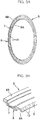
FIG. 2] FIG. 2A is a perspective view of the rolling bearing seal, andFig. 2B is a major-part enlarged vertical sectional perspective view thereof. - [
FIG. 3] FIG. 3A is a major-part enlarged vertical sectional view of a seal lip portion and a seal sliding surface of an inner ring as seen in the radial direction, andFIG. 3B is a major-part enlarged vertical sectional view thereof as seen in the axial direction. - [
FIG. 4] FIG. 4A is a vertical sectional view of a compression vulcanization molding mold for the rolling bearing seal according to the embodiment of the present invention, andFIG. 4B is a major-part enlarged vertical sectional perspective view thereof. - [
FIG. 5] FIG. 5 is a perspective view showing a state in which the compression vulcanization molding mold is opened and a core metal is placed at a guide portion of a female mold. - [
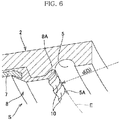
FIG. 6] FIG. 6 is a major-part enlarged perspective view showing a state in which the rolling bearing seal is molded by the compression vulcanization molding mold, while the female mold is not shown. - [
FIG. 7] FIG. 7A is a vertical sectional view of a conventional compression vulcanization molding mold for rolling bearing seal, andFIG. 7B is a major-part enlarged vertical sectional perspective view thereof. - [
FIG. 8] FIG. 8 is a perspective view showing a state in which the conventional compression vulcanization molding mold for rolling bearing seal is opened and a core metal is placed at a guide portion of a female mold. - Next, embodiments of the present invention will be described in detail with reference to the accompanying drawings. Here, the present invention is not limited to embodiments shown in the accompanying drawings, but includes all the embodiments that satisfy requirements described in the claims.
- As used herein, the direction of the rotation axis of a rolling bearing is referred to as an "axial direction", and a "radial direction" and a "circumferential direction" are defined using the rotation axis as a reference.
- As shown in a major-part enlarged vertical sectional view in
FIG. 1 , a rolling bearing B with a seal according to an embodiment of the present invention includes: aninner ring 11; anouter ring 12; a plurality of rollingelements 13. which roll between theinner ring 11 and theouter ring 12; aretainer 14 which retains the rollingelements 13 at regular intervals in the circumferential direction; and a pair of rolling bearing seals S separated from each other in the axial direction. - The seals S provide separation between a bearing internal space G and outside, and lubricating oil is supplied to the bearing internal space G by appropriate means such as grease or oil bath.
- On the external side with respect to the seals S, various foreign matters such as wear powder of a gear or the like, or minute crushed stones, exist depending on a target to which the rolling bearing B with the seal is mounted. Such powdery foreign matters can reach the vicinity of the rolling bearing B by flow of lubricating oil or air. The seals S prevent entry of the foreign matters into the bearing internal space G from outside.
- Each of the seals S includes: an
annular core metal 7 made of metal, such as a cold rolled steel sheet (SPCC), an electro galvanized steel sheet (SECC), or a stainless steel sheet (SUS); andrubber 8 adhered to thecore metal 7 by vulcanization. Therubber 8 includes: an annularseal lip portion 8A extending inward in the radial direction from the inner-diameter side of thecore metal 7 and to slide on a seal sliding surface F of theinner ring 11 in the circumferential direction; and anattachment portion 8B extending outward in the radial direction from the outer-diameter side of thecore metal 8 and to be attached to a seal groove H of theouter ring 12. - Types of the rolling bearing B with the seal include an inner ring rotation type in which the
inner ring 11 rotates, and an outer ring rotation type in which theouter ring 12 rotates. The rolling bearing seal S having theseal lip 8A on the inner diameter side and theattachment portion 8B on the outer diameter side is applicable to both of the inner ring rotation type and the outer ring rotation type. - Here, the
rubber 8 of the seal S may be made from a material obtained by appropriately blending one kind or two or more kinds of rubbers such as nitrile rubber (NBR), hydrogenated nitrile rubber (HNBR), acrylic rubber (ACM), ethylene acrylic rubber (AEM), fluororubber (FKM, FPM), and silicone rubber (VQM), as a rubber material having high oil resistance. - Considering ease of kneading of the rubber material, vulcanization moldability, and adhesion to the
core metal 7, it is also preferable to blend another kind of rubber such as liquid NBR, ethylene propylene rubber (EPDM), natural rubber (NR), isoprene rubber (IR), styrene butadiene rubber (SBR), or butadiene rubber (BR). - As shown in the perspective view in
FIG. 2A , the major-part enlarged vertical sectional perspective view inFIG. 2B , the major-part enlarged vertical sectional view as seen in the radial direction inFIG. 3A , and the major-part enlarged vertical sectional view as seen in the axial direction inFIG. 3B , theseal lip portion 8A of the rolling bearing seal S according to the embodiment of the present invention has a plurality ofprojections 10 to form, between the seal sliding surface F and theseal lip portion 8A,oil passages 9 that allow communication between the bearing internal space G and outside. The plurality ofprojections 10 are formed over the entire circumference in the circumferential direction of theseal lip portion 8A of the rolling bearing seal S. Further, the plurality ofprojections 10 are each formed, from the end of theseal lip portion 8A, over the entire area that can face the seal sliding surface F in the radial direction. Thus, along with rotation of the rolling bearing B, lubricating oil in theoil passages 9 is drawn to enter between the seal sliding surface F and theseal lip portion 8A owing to wedge effect, whereby formation of an oil film is promoted uniformly over the entire circumference of the seal sliding surface F. This results in a state in which theseal lip portion 8A and the seal sliding surface F are completely separated from each other by the oil film so as not to be in direct contact with each other (i.e., hydrodynamic lubrication). - Thus, torque reduction and speed increase of the rolling bearing B with the seal can be achieved.
- The plurality of
projections 10 provided in theseal lip portion 8A of the rolling bearing seal S according to the present embodiment are formed at regular intervals over the entire circumference in the circumferential direction. However, the present invention is not limited to the case where the plurality ofprojections 10 are formed at regular intervals over the entire circumference in the circumferential direction. That is, the plurality ofprojections 10 may be formed at irregular intervals. - Next, a mold A used for compression vulcanization molding of the rolling bearing seal S, and a method for manufacturing the rolling bearing seal S using the mold A, according to the embodiment of the present invention will be described.
- As shown in a vertical sectional view in
FIG. 4A , a major-part enlarged vertical sectional perspective view inFIG. 4B , and a perspective view inFIG. 5 , the compression vulcanization molding mold A includes afemale mold 1 and amale mold 2 which form an annular cavity C for forming therubber 8 of the seal S. - The female mold (a lower mold or a die) 1 has a
guide portion 3 for positioning thecore metal 7 of the seal S, and has a rugged shape 4 forming the plurality ofprojections seal lip portion 8A. - The male mold (an upper mold or a punch) 2 has an inner-diameter-
side burr groove 5 and an outer-diameter-side burr groove 6 respectively at an inner-diameter-side peripheral portion C1 and an outer-diameter-side peripheral portion C2 of the cavity C, and the shape of a radiallyoutermost portion 5A of the inner-diameter-side burr groove 5 is formed to be a circle. - As shown in a major-part enlarged perspective view in
FIG. 6 in which the female mold is not shown, in the present embodiment, a diameter d of the circle represented by the shape of the radiallyoutermost portion 5A of the inner-diameter-side burr groove 5 is set to be equal to a diameter D of a circle E (see alsoFIG. 2B ) in contact with the ends of the plurality ofprojections 10 of theseal lip portion 8A. - It is noted that the diameter d (mm) of the circle represented by the shape of the radially
outermost portion 5A of the inner-diameter-side burr groove 5 has only to be set within a range of (D - 0.2) ≤ d ≤ D relative to the diameter D (mm) of the circle E in contact with the ends of the plurality ofprojections 10. Setting the diameter d within the range of the above inequality enhances reliability of molding of therubber 8 having the plurality of projections at the end of theseal lip portion 8A in manufacturing of the rolling bearing seal S using the compression vulcanization molding mold A, because 0.2 (mm) is a burr size within a tolerable range. - An example of the method for manufacturing the bearing seal S using the compression vulcanization molding mold A will be described.
- First, as shown in
FIG. 5 , in a state in which the mold A is opened, thecore metal 7 is placed at theguide portion 3 of thefemale mold 1. - Before the step of placing the
core metal 7 on thefemale mold 1, a thermosetting resin adhesive agent may be applied to an area of thecore metal 7, which is to be in contact with therubber 8, and indirect vulcanization (crosslinking) adhesion may be performed in a subsequent rubber material vulcanization step. Alternatively, direct vulcanization (crosslinking) adhesion may be performed without application of the adhesive agent, in the subsequent rubber material vulcanization step. - Next, for example, a rubber sheet which is an unvulcanized rubber material is placed in the
female mold 1. The volume of the rubber sheet is set to be greater than the volume of the annular cavity C for forming therubber 8. - Next, as shown in
FIG. 4A , the mold A is closed, and then pressed and heated to vulcanize the rubber sheet. An extra unvulcanized rubber material is leaked out to theburr grooves female mold 1 and themale mold 2. - Next, the mold A is opened and the rolling bearing seal S as a molded product, shown in
FIG. 2A andFIG. 4A , is taken out of the mold A. - In the state where the rolling bearing seal S that is the molded product is taken out of the mold A, the plurality of
projections 10 are formed from the end of theseal lip portion 8A over the entire area that can face the seal sliding surface F in the radial direction. In addition, on the plurality ofprojections 10 at the end of theseal lip portion 8A, thin burr occurs between theadjacent projections 10. However, this burr protrudes outward in the axial direction of the rolling bearing B and has a burr size within a tolerable range, so that the burr does not come into contact with the seal sliding surface F as shown inFIG. 3A . Therefore, the burr does not impair the function of the rolling bearing seal S and thus does not cause a problem. - In the compression vulcanization molding mold A for the rolling bearing seal and the method for manufacturing the rolling bearing seal S, configured as described above, the shape of the radially
outermost portion 5A of the inner-diameter-side burr groove 5 of themale mold 2 is a circle. Therefore, as compared to the conventional mold A' (FIGS. 7A, 7B , and8 ) in which the radiallyoutermost portion 5A' of the inner-diameter-side burr groove 5' of the male mold 2' has a rugged shape (corrugated shape), the shape of themale mold 2 is simplified and thus the cost for manufacturing the mold A can be reduced. - In addition, in the compression vulcanization molding mold A and the method for manufacturing the rolling bearing seal S, configured as described above, the size of burr to occur is set within a tolerable range, whereby it is possible to form the plurality of
projections 10, from the end of theseal lip portion 8A, over the entire area that can face the seal sliding surface F in the radial direction. - Moreover, as compared to the conventional mold A', it is not necessary to perform alignment (angle matching) of the
female mold 1 and themale mold 2 accurately in the circumferential direction, and thus productivity can be improved. -
- 1 female mold (lower mold, die)
- 2, 2' male mold (upper mold, punch)
- 3 guide portion
- 4 rugged shape
- 5, 5' inner-diameter-side burr groove
- 5A, 5A' radially outermost portion
- 6 outer-diameter-side burr groove
- 7 core metal
- 8 rubber
- 8A seal lip portion
- 8B attachment portion
- 9 oil passage
- 10 projection
- 11 inner ring
- 12 outer ring
- 13 rolling element
- 14 retainer
- A, A' compression vulcanization molding mold
- B rolling bearing with seal
- C cavity
- C1 inner-diameter-side peripheral portion
- C2 outer-diameter-side peripheral portion
- D diameter of circle in contact with ends of projections of seal lip portion
- d diameter of circle represented by shape of radially outermost portion of inner-diameter-side burr groove
- E circle in contact with ends of projections of seal lip portion
- F seal sliding surface
- G bearing internal space
- H seal groove
- I radial-direction gap
- S rolling bearing seal
Claims (3)
- A compression vulcanization molding mold for a rolling bearing seal, which is used for compression vulcanization molding of the rolling bearing seal that separates, from outside, a bearing internal space formed between an inner ring and an outer ring of a rolling bearing, wherein
the rolling bearing seal includes an annular core metal and rubber adhered to the core metal by vulcanization,the rubber includes: a seal lip portion that extends inward in a radial direction from an inner diameter side of the core metal, and slides on a seal sliding surface of the inner ring in a circumferential direction; and an attachment portion that extends outward in the radial direction from an outer diameter side of the core metal, and is attached to the outer ring, andthe seal lip portion has, over an entire circumference in the circumferential direction, a plurality of projections to form, between the seal sliding surface and the seal lip portion, oil passages that allow communication between the bearing internal space and the outside,the mold comprising:
a female mold and a male mold which form an annular cavity for molding the rubber, whereinthe female mold has a guide portion for positioning the core metal, and a rugged shape forming the projections on the seal lip portion, andthe male mold has an inner-diameter-side burr groove and an outer-diameter-side burr groove respectively at an inner-diameter-side peripheral portion and an outer-diameter-side peripheral portion of the cavity, and a shape of a radially outermost portion of the inner-diameter-side burr groove is formed in a circle. - The compression vulcanization molding mold for rolling bearing seal, according to claim 1, wherein
a diameter d (mm) of the circle represented by the shape of the radially outermost portion of the inner-diameter-side burr groove is set within a range of (D - 0.2) ≤ d ≤ D relative to a diameter D (mm) of a circle in contact with an end of each of the projections. - A rolling bearing seal manufacturing method for performing compression vulcanization molding of a rolling bearing seal using the compression vulcanization molding mold for rolling bearing seal according to claim 1 or 2, the method comprising:opening the mold and placing the core metal at the guide portion of the female mold;placing an unvulcanized rubber material in the female mold;closing the mold and pressing and heating the mold to vulcanize the rubber material; andopening the mold and taking the rolling bearing seal that is a molded product, out of the mold.
Applications Claiming Priority (2)
| Application Number | Priority Date | Filing Date | Title |
|---|---|---|---|
| JP2017012017A JP6836152B2 (en) | 2017-01-26 | 2017-01-26 | Mold for compression vulcanization of rolling bearing seals and manufacturing method of rolling bearing seals |
| PCT/JP2017/037490 WO2018138981A1 (en) | 2017-01-26 | 2017-10-17 | Compression vulcanization molding mold for rolling bearing seal, and method for manufacturing rolling bearing seal |
Publications (2)
| Publication Number | Publication Date |
|---|---|
| EP3575640A1 true EP3575640A1 (en) | 2019-12-04 |
| EP3575640A4 EP3575640A4 (en) | 2020-10-14 |
Family
ID=62978247
Family Applications (1)
| Application Number | Title | Priority Date | Filing Date |
|---|---|---|---|
| EP17894047.4A Pending EP3575640A4 (en) | 2017-01-26 | 2017-10-17 | PRESSURE VULCANIZATION CASTING FORM FOR ROLLING BEARING SEAL AND PROCESS FOR PRODUCING A ROLLING BEARING SEAL |
Country Status (5)
| Country | Link |
|---|---|
| US (1) | US11440226B2 (en) |
| EP (1) | EP3575640A4 (en) |
| JP (1) | JP6836152B2 (en) |
| CN (1) | CN110168261B (en) |
| WO (1) | WO2018138981A1 (en) |
Families Citing this family (7)
| Publication number | Priority date | Publication date | Assignee | Title |
|---|---|---|---|---|
| WO2020045072A1 (en) * | 2018-08-29 | 2020-03-05 | Nok株式会社 | Seal member manufacturing method and molding mold |
| JP7478411B2 (en) * | 2020-02-17 | 2024-05-07 | 内山工業株式会社 | Mold |
| JP2022189011A (en) * | 2021-06-10 | 2022-12-22 | 株式会社神戸製鋼所 | Mold, apparatus and method for manufacturing metal-resin composite |
| CN113910503B (en) * | 2021-10-20 | 2025-04-29 | 厦门正新橡胶工业有限公司 | A vulcanization mold for tire |
| JP7768821B2 (en) * | 2022-04-11 | 2025-11-12 | 矢崎総業株式会社 | Manufacturing method of molded products |
| WO2024176474A1 (en) * | 2023-02-24 | 2024-08-29 | 株式会社ジェイテクト | Sliding member and rolling bearing |
| CN117261080A (en) * | 2023-10-13 | 2023-12-22 | 新乡航空工业(集团)有限公司 | A leather bowl lip direct vulcanization mold and processing method |
Family Cites Families (28)
| Publication number | Priority date | Publication date | Assignee | Title |
|---|---|---|---|---|
| US3501155A (en) * | 1967-05-22 | 1970-03-17 | Gen Motors Corp | Bi-directional seal |
| US3572732A (en) * | 1969-02-26 | 1971-03-30 | Mather Co | Double load area lip seal |
| US3895814A (en) * | 1971-08-10 | 1975-07-22 | Parker Hannifin Corp | Rotary shaft seal |
| CH567927A5 (en) * | 1974-08-21 | 1975-10-15 | Schiesser Ag | |
| DE2556992C2 (en) * | 1975-12-18 | 1980-04-24 | Goetze Ag, 5093 Burscheid | Shaft seal |
| US4399998A (en) * | 1981-12-28 | 1983-08-23 | The Timken Company | Self-venting seal lip |
| US4770424A (en) * | 1985-12-19 | 1988-09-13 | The Timken Company | Compact labyrinth-type seal |
| FR2636691B1 (en) * | 1988-09-20 | 1994-12-09 | Roulements Soc Nouvelle | BEARING WITH SEAL |
| JP3242517B2 (en) * | 1993-12-29 | 2001-12-25 | 東洋シール工業株式会社 | Bearing sealing plate and method of manufacturing the same |
| US5921555A (en) * | 1997-04-10 | 1999-07-13 | Freudenberg-Nok General Partnership | Uni-directional seal for use on a shaft |
| US6409177B1 (en) * | 1999-08-23 | 2002-06-25 | Freudenberg-Nok General Partnership | Rotary shaft seal |
| JP4461518B2 (en) * | 1999-08-27 | 2010-05-12 | 住友化学株式会社 | Mold for manufacturing thermoplastic resin molded body and method for manufacturing thermoplastic resin molded body |
| JP4419641B2 (en) * | 2004-03-29 | 2010-02-24 | 日産自動車株式会社 | Mounting structure for vehicle headlamps |
| US7563050B2 (en) * | 2004-07-15 | 2009-07-21 | Temper Corporation | Rings for mounting structures to shafts and methods of using such rings |
| US8657299B2 (en) * | 2004-07-15 | 2014-02-25 | John E. Rode | Mounting rings for shafts |
| WO2008059790A1 (en) * | 2006-11-14 | 2008-05-22 | Ntn Corporation | Sealed rolling bearing |
| JP5126999B2 (en) * | 2008-03-13 | 2013-01-23 | 日本バルカー工業株式会社 | Sealing material |
| US8596872B2 (en) * | 2009-10-13 | 2013-12-03 | Amsted Rail Company, Inc. | Roller bearing seal |
| JP2013007463A (en) | 2011-06-27 | 2013-01-10 | Ntn Corp | Bearing with seal |
| CN103620247B (en) * | 2011-06-27 | 2016-08-24 | Ntn株式会社 | Rolling bearing |
| KR102051171B1 (en) * | 2012-06-04 | 2019-12-02 | 테네코 인코퍼레이티드 | Radial shaft seal and assembly therewith |
| JP6522357B2 (en) * | 2015-02-06 | 2019-05-29 | Ntn株式会社 | Rolling bearing |
| WO2016143786A1 (en) * | 2015-03-09 | 2016-09-15 | Ntn株式会社 | Sealed bearing |
| EP3269989B1 (en) | 2015-03-09 | 2021-07-21 | NTN Corporation | Sealed bearing |
| JP2016166654A (en) | 2015-03-10 | 2016-09-15 | Ntn株式会社 | Rolling bearing with seal |
| JP2016166655A (en) | 2015-03-10 | 2016-09-15 | Ntn株式会社 | Rolling bearing with seal |
| JP6609460B2 (en) | 2015-11-13 | 2019-11-20 | 内山工業株式会社 | Manufacturing method of molding die and sealing device |
| JP6789739B2 (en) * | 2016-09-08 | 2020-11-25 | Ntn株式会社 | Bearing with seal |
-
2017
- 2017-01-26 JP JP2017012017A patent/JP6836152B2/en active Active
- 2017-10-17 US US16/479,140 patent/US11440226B2/en active Active
- 2017-10-17 CN CN201780082936.5A patent/CN110168261B/en active Active
- 2017-10-17 EP EP17894047.4A patent/EP3575640A4/en active Pending
- 2017-10-17 WO PCT/JP2017/037490 patent/WO2018138981A1/en not_active Ceased
Also Published As
| Publication number | Publication date |
|---|---|
| US20190351590A1 (en) | 2019-11-21 |
| CN110168261A (en) | 2019-08-23 |
| EP3575640A4 (en) | 2020-10-14 |
| CN110168261B (en) | 2021-05-11 |
| JP6836152B2 (en) | 2021-02-24 |
| WO2018138981A1 (en) | 2018-08-02 |
| JP2018119624A (en) | 2018-08-02 |
| US11440226B2 (en) | 2022-09-13 |
Similar Documents
| Publication | Publication Date | Title |
|---|---|---|
| US11440226B2 (en) | Compression vulcanization molding mold for rolling bearing seal, and method for manufacturing rolling bearing seal | |
| EP3553353B1 (en) | Sliding component | |
| EP1967749B1 (en) | Tapered roller bearing with lubrication | |
| EP2765339A1 (en) | Seal ring | |
| EP3073158B1 (en) | Method for manufacturing sealing device | |
| EP2857703B1 (en) | Outer ring rotation bearing | |
| EP2821661B1 (en) | Sealing device | |
| US11028925B2 (en) | Seal ring | |
| CN106662250A (en) | Sealing device | |
| JP2009092223A (en) | Sealing device for universal joint | |
| CN101868639B (en) | Sealing device, rolling bearing, and rolling bearing for wheel | |
| CN107429844A (en) | Sealing ring | |
| JP5455429B2 (en) | Sealed bearing | |
| EP3822503A1 (en) | Sealing device | |
| EP3385579B1 (en) | Seal device | |
| JP7121135B2 (en) | sealing device | |
| JP2010180983A (en) | Sealing structure and bearing device | |
| US20200340588A1 (en) | Sealing device and method for making slinger | |
| CN107816493B (en) | Universal joint comprising a seal, seal and method for mounting a seal | |
| US11692632B2 (en) | Sealing arrangement for an electric machine, manufacturing method of sealing and sealing method | |
| JP7478411B2 (en) | Mold | |
| US8202006B2 (en) | Sealing device, rolling bearing, and rolling bearing for wheel | |
| US12442449B2 (en) | Bidirectional hydrodynamic rotary seal | |
| US20190178382A1 (en) | Seal ring | |
| JP2012017804A (en) | Tapered roller bearing |
Legal Events
| Date | Code | Title | Description |
|---|---|---|---|
| STAA | Information on the status of an ep patent application or granted ep patent |
Free format text: STATUS: THE INTERNATIONAL PUBLICATION HAS BEEN MADE |
|
| PUAI | Public reference made under article 153(3) epc to a published international application that has entered the european phase |
Free format text: ORIGINAL CODE: 0009012 |
|
| STAA | Information on the status of an ep patent application or granted ep patent |
Free format text: STATUS: REQUEST FOR EXAMINATION WAS MADE |
|
| 17P | Request for examination filed |
Effective date: 20190826 |
|
| AK | Designated contracting states |
Kind code of ref document: A1 Designated state(s): AL AT BE BG CH CY CZ DE DK EE ES FI FR GB GR HR HU IE IS IT LI LT LU LV MC MK MT NL NO PL PT RO RS SE SI SK SM TR |
|
| AX | Request for extension of the european patent |
Extension state: BA ME |
|
| DAV | Request for validation of the european patent (deleted) | ||
| DAX | Request for extension of the european patent (deleted) | ||
| A4 | Supplementary search report drawn up and despatched |
Effective date: 20200914 |
|
| RIC1 | Information provided on ipc code assigned before grant |
Ipc: F16C 33/78 20060101ALI20200908BHEP Ipc: B29C 33/02 20060101ALI20200908BHEP Ipc: B29C 43/36 20060101ALI20200908BHEP Ipc: F16C 19/06 20060101ALI20200908BHEP Ipc: F16J 15/3204 20160101ALI20200908BHEP Ipc: F16J 15/00 20060101AFI20200908BHEP Ipc: B29C 35/02 20060101ALI20200908BHEP |
|
| STAA | Information on the status of an ep patent application or granted ep patent |
Free format text: STATUS: EXAMINATION IS IN PROGRESS |
|
| 17Q | First examination report despatched |
Effective date: 20230206 |