EP3575639A1 - Gearbox system with add-on cooling fin panels - Google Patents
Gearbox system with add-on cooling fin panels Download PDFInfo
- Publication number
- EP3575639A1 EP3575639A1 EP19177684.8A EP19177684A EP3575639A1 EP 3575639 A1 EP3575639 A1 EP 3575639A1 EP 19177684 A EP19177684 A EP 19177684A EP 3575639 A1 EP3575639 A1 EP 3575639A1
- Authority
- EP
- European Patent Office
- Prior art keywords
- gearbox
- cooling fin
- cooling
- fin panel
- housing
- Prior art date
- Legal status (The legal status is an assumption and is not a legal conclusion. Google has not performed a legal analysis and makes no representation as to the accuracy of the status listed.)
- Granted
Links
- 238000001816 cooling Methods 0.000 title claims abstract description 131
- 230000008878 coupling Effects 0.000 claims description 14
- 238000010168 coupling process Methods 0.000 claims description 14
- 238000005859 coupling reaction Methods 0.000 claims description 14
- 229910052782 aluminium Inorganic materials 0.000 claims description 10
- XAGFODPZIPBFFR-UHFFFAOYSA-N aluminium Chemical compound [Al] XAGFODPZIPBFFR-UHFFFAOYSA-N 0.000 claims description 10
- 239000004519 grease Substances 0.000 claims description 4
- 239000003638 chemical reducing agent Substances 0.000 claims description 3
- 238000004519 manufacturing process Methods 0.000 description 6
- 229910001018 Cast iron Inorganic materials 0.000 description 4
- RYGMFSIKBFXOCR-UHFFFAOYSA-N Copper Chemical compound [Cu] RYGMFSIKBFXOCR-UHFFFAOYSA-N 0.000 description 3
- 238000005266 casting Methods 0.000 description 3
- 239000010949 copper Substances 0.000 description 3
- 239000000463 material Substances 0.000 description 3
- 230000008901 benefit Effects 0.000 description 2
- 229910052802 copper Inorganic materials 0.000 description 2
- 229910052751 metal Inorganic materials 0.000 description 2
- 239000002184 metal Substances 0.000 description 2
- 238000000034 method Methods 0.000 description 2
- 238000012986 modification Methods 0.000 description 2
- 230000004048 modification Effects 0.000 description 2
- 229910000755 6061-T6 aluminium alloy Inorganic materials 0.000 description 1
- 229910000838 Al alloy Inorganic materials 0.000 description 1
- 229910000881 Cu alloy Inorganic materials 0.000 description 1
- 238000005299 abrasion Methods 0.000 description 1
- 230000002411 adverse Effects 0.000 description 1
- 229910045601 alloy Inorganic materials 0.000 description 1
- 239000000956 alloy Substances 0.000 description 1
- 230000004075 alteration Effects 0.000 description 1
- 230000000295 complement effect Effects 0.000 description 1
- 238000004512 die casting Methods 0.000 description 1
- 239000000428 dust Substances 0.000 description 1
- -1 e.g. Inorganic materials 0.000 description 1
- 238000005516 engineering process Methods 0.000 description 1
- 238000001125 extrusion Methods 0.000 description 1
- 238000003754 machining Methods 0.000 description 1
- 239000007769 metal material Substances 0.000 description 1
- 230000008569 process Effects 0.000 description 1
- 230000000135 prohibitive effect Effects 0.000 description 1
- 230000001737 promoting effect Effects 0.000 description 1
- 230000003746 surface roughness Effects 0.000 description 1
- XLYOFNOQVPJJNP-UHFFFAOYSA-N water Substances O XLYOFNOQVPJJNP-UHFFFAOYSA-N 0.000 description 1
Images


Classifications
-
- F—MECHANICAL ENGINEERING; LIGHTING; HEATING; WEAPONS; BLASTING
- F16—ENGINEERING ELEMENTS AND UNITS; GENERAL MEASURES FOR PRODUCING AND MAINTAINING EFFECTIVE FUNCTIONING OF MACHINES OR INSTALLATIONS; THERMAL INSULATION IN GENERAL
- F16H—GEARING
- F16H57/00—General details of gearing
- F16H57/04—Features relating to lubrication or cooling or heating
- F16H57/0412—Cooling or heating; Control of temperature
- F16H57/0415—Air cooling or ventilation; Heat exchangers; Thermal insulations
-
- F—MECHANICAL ENGINEERING; LIGHTING; HEATING; WEAPONS; BLASTING
- F16—ENGINEERING ELEMENTS AND UNITS; GENERAL MEASURES FOR PRODUCING AND MAINTAINING EFFECTIVE FUNCTIONING OF MACHINES OR INSTALLATIONS; THERMAL INSULATION IN GENERAL
- F16H—GEARING
- F16H57/00—General details of gearing
- F16H57/04—Features relating to lubrication or cooling or heating
- F16H57/0412—Cooling or heating; Control of temperature
- F16H57/0415—Air cooling or ventilation; Heat exchangers; Thermal insulations
- F16H57/0416—Air cooling or ventilation
-
- F—MECHANICAL ENGINEERING; LIGHTING; HEATING; WEAPONS; BLASTING
- F16—ENGINEERING ELEMENTS AND UNITS; GENERAL MEASURES FOR PRODUCING AND MAINTAINING EFFECTIVE FUNCTIONING OF MACHINES OR INSTALLATIONS; THERMAL INSULATION IN GENERAL
- F16H—GEARING
- F16H57/00—General details of gearing
- F16H57/02—Gearboxes; Mounting gearing therein
- F16H57/031—Gearboxes; Mounting gearing therein characterised by covers or lids for gearboxes
-
- F—MECHANICAL ENGINEERING; LIGHTING; HEATING; WEAPONS; BLASTING
- F28—HEAT EXCHANGE IN GENERAL
- F28F—DETAILS OF HEAT-EXCHANGE AND HEAT-TRANSFER APPARATUS, OF GENERAL APPLICATION
- F28F3/00—Plate-like or laminated elements; Assemblies of plate-like or laminated elements
- F28F3/02—Elements or assemblies thereof with means for increasing heat-transfer area, e.g. with fins, with recesses, with corrugations
- F28F3/04—Elements or assemblies thereof with means for increasing heat-transfer area, e.g. with fins, with recesses, with corrugations the means being integral with the element
- F28F3/048—Elements or assemblies thereof with means for increasing heat-transfer area, e.g. with fins, with recesses, with corrugations the means being integral with the element in the form of ribs integral with the element or local variations in thickness of the element, e.g. grooves, microchannels
-
- F—MECHANICAL ENGINEERING; LIGHTING; HEATING; WEAPONS; BLASTING
- F28—HEAT EXCHANGE IN GENERAL
- F28F—DETAILS OF HEAT-EXCHANGE AND HEAT-TRANSFER APPARATUS, OF GENERAL APPLICATION
- F28F3/00—Plate-like or laminated elements; Assemblies of plate-like or laminated elements
- F28F3/02—Elements or assemblies thereof with means for increasing heat-transfer area, e.g. with fins, with recesses, with corrugations
- F28F3/06—Elements or assemblies thereof with means for increasing heat-transfer area, e.g. with fins, with recesses, with corrugations the means being attachable to the element
-
- F—MECHANICAL ENGINEERING; LIGHTING; HEATING; WEAPONS; BLASTING
- F16—ENGINEERING ELEMENTS AND UNITS; GENERAL MEASURES FOR PRODUCING AND MAINTAINING EFFECTIVE FUNCTIONING OF MACHINES OR INSTALLATIONS; THERMAL INSULATION IN GENERAL
- F16H—GEARING
- F16H57/00—General details of gearing
- F16H57/02—Gearboxes; Mounting gearing therein
- F16H2057/02017—Gearboxes; Mounting gearing therein characterised by special features related to the manufacturing of the gear case, e.g. special adaptations for casting
Definitions
- the present application relates generally to gearbox systems, and more particularly, but not exclusively, to gearbox systems having cooling fins.
- Gearbox systems remain an area of interest. Some existing systems have various shortcomings, drawbacks and disadvantages relative to certain applications. For example, in some gearbox system configurations, the power density of the gearbox may be improved. Accordingly, there remains a need for further contributions in this area of technology.
- One embodiment of the present invention is a unique gearbox system having add-on cooling fin panels.
- Other embodiments include apparatuses, systems, devices, hardware, methods, and combinations for gearbox systems and cooling fin panels. Further embodiments, forms, features, aspects, benefits, and advantages of the present application shall become apparent from the description and figures provided herewith.
- Gearbox system 10 includes a gearbox 12.
- gearbox 12 is a gear reducer, i.e., a speed-reducing gearbox.
- gearbox 12 may be a speed-increasing gearbox. In yet other embodiments gearbox 12 may be another type of gearbox.
- Gearbox 12 includes a housing 14 having external surface 16, a fan or impeller 18, a shroud 20, an input shaft 22 and an output shaft 24.
- housing 14 is a cast housing, e.g., a cast iron housing. In other embodiments, housing 14 may be an aluminum or other casting. In some embodiments, housing 14 may be a machined or welded housing.
- External surface 16 is employed for extracting heat from gearbox 12 through housing 14, i.e., for cooling gearbox 12.
- External surface 16 has a contoured shape 26.
- Contoured shape 26 includes a plurality of flat portions 28, a plurality of curved portions 30, and a plurality of curved portions 32. Curved portions 32 are more gently curved than curved portions 30.
- Fan or impeller 18 is coupled to input shaft 22, and is constructed to generate a cooling airflow 34.
- Fan or impeller 18 may be, for example, a radial or centrifugal fan and/or an axial fan, or an impeller.
- Shroud 20 is constructed to direct cooling airflow 34 from fan or impeller 18 over external surface 16, and over and/or through a plurality of cooling fins 38 (described below).
- Gear reducers and other types of gearboxes may be thermally limited, due to internal power losses (e.g., gear churning, mesh, and bearing drag losses).
- the internal power losses generate heat, which drives up the temperature of the gearbox, which may adversely affect the life of the gearbox under some conditions, and which may limit the power density of the gearbox.
- a scheme to provide or improve gearbox cooling may be employed as an add-on feature.
- Embodiments of the present invention include the use of add-on cooling fin panels 36, which reduce the operating temperatures of gearbox 12, which may permit gearbox 12 to transmit more power and/or torque, and which thus may increase the power density of gearbox 12.
- cooling fins may be formed as part of a cast iron housing
- cast fins typically have a low fin efficiency because the thermal conductivity of cast iron is low, e.g., compared to aluminum or copper.
- it may be undesirably difficult and cost prohibitive to manufacture the slender fins that are preferred using the standard casting processes used to form typical cast gearbox housings.
- some customers prefer gearbox housings without fins.
- gearbox system 10 includes a plurality of add-on cooling fin panels 36 affixed to external surface 16 of housing 14 of gearbox 12.
- Each cooling fin panel 36 includes a plurality of cooling fins 38 extending from a base 40.
- base 40 is defined by the largest dimension(s) of cooling fin panels 36, in order to maximize heat transfer through cooling fin panels 36.
- Cooling fins 38 are of a slender configuration that is unavailable with cast gearbox housings configurations. Cooling fin panels 36 are constructed to transfer heat from external surface 16 of housing 14 by conduction, e.g., though base 40, and to transfer heat to the environment 46 in which gearbox 12 is located by convection, e.g., via cooling fins 38.
- Cooling fin panels 36 are referred to as "add-on" because they are added to gearbox 12, e.g., subsequent to the casting or other manufacture of housing 14, and in some embodiments, subsequent to the manufacture of gearbox 12; and because cooling fin panels 36 are formed to mate with housing 14 and are not formed as part of or integral to housing 14. In some embodiments, cooling fin panels 36 may be added to gearbox 12 during the manufacture of gearbox 12 or added prior to the delivery of gearbox 12 to a customer or end-user. In some embodiments, cooling fin panels 36 may be added to gearbox 12 by the customer or end-user.
- Cooling fin panels 36 are in thermal engagement with external surface 16, and are thermally and mechanically coupled to external surface 16.
- base 40 is in contact with external surface 16 of housing 14 for transferring heat from housing 14 to each cooling fin panel 36.
- cooling fin panels 36 are constructed to match and engage the contoured shape 26 of housing 14.
- base 40 of cooling fin panels 36 may be formed to match and complement the contour of the corresponding flat portions 28, curved portions 30, and/or curved portions 32 of housing 14, e.g., in order to maximize effective thermal contact area between cooling fin panels 36 and housing 14.
- thermal coupling layer 44 disposed between cooling fin panels 36 and external surface 16 of housing 14.
- a thermal coupling layer 44 is in contact with both base 40 of each cooling fin panel 36 and with external surface 16 of housing 14.
- Thermal coupling layer 44 is constructed to thermally couple each respective cooling fin panel 36 with housing 14, and to enhance heat transfer from housing 14 to each respective cooling fin panel 36.
- thermal coupling layer 44 is constructed to increase thermal contact area between external surface 16 and base 40 by filling in gaps between external surface 16 and base 40, e.g., gaps stemming from manufacturing tolerances or other manufacturing variations that otherwise prevent 100% contact engagement between base 40 and external surface 16.
- thermal coupling layer 44 is also or alternatively constructed to increase thermal contact area between external surface 16 and base 40 by filing in and compensating for surface variations or asperities associated with the surface roughness of surface 16 and base 40.
- Thermal coupling layer 44 may be, for example, a thermal grease, a thermal paste, thermal contact pads and/or another layer or other structure constructed and operative to thermally couple cooling fin panels 36 with housing 14, and to enhance conductive heat transfer from housing 14 to each respective cooling fin panel 36, e.g., as described hereinabove.
- Cooling fin panels 36 are formed of a metallic material. Preferably, cooling fin panels 36 are formed of a material having a thermal conductivity as high as or higher than that of the material that forms housing 14. In one non-limiting example, housing 14 is formed of cast iron. In one non-limiting example, cooling fin panels 36 are made of aluminum, e.g., 6061-T6 aluminum. In other embodiments, cooling fin panels 36 may be made of copper or a copper and/or aluminum alloy or another metal or alloy. When made of aluminum, cooling fin panels 36 may be anodized, e.g., for improved convection and for abrasion resistance to dust and debris. Cooling fin panels 36 may be made by die-casting, extrusion, and/or may be made by water jetting or other machining/material removal processes. In some embodiments, cooling fin panels 36 may be in the form of folded sheet metal structures.
- cooling fins 38 are slender, e.g., have a slender aspect ratio, with a pitch-to-height ratio between 0.05 and 0.6. More preferably, the pitch-to-height ratio is approximately 0.2. In other embodiments, cooling fins 38 may have one or more other pitch-to-height ratios. Cooling fins 38 may be rectangular, triangular, or may have another shape such as a pin or cylindrical shape. Cooling fins 38 may be, for example, smooth, or serrated.
- cooling fin panels 36 are releasably attached to housing 14 of gearbox 12, in particular, to external surface 16 of housing 14.
- attachment features 42 may be constructed to affix cooling panels 36 to housing 14 of gearbox 12.
- attachment features 42 may be constructed to releasably affix cooling fin panels 36 to housing 14 of gearbox 12.
- cooling fin panels 36 may be attached to housing 14 via the use of attachment features 42 in the form of fasteners such as screws.
- the fasteners may be unscrewed or otherwise uninstalled, allowing the removal of cooling fin panels 36 from gearbox 12.
- the fasteners or other attachment features 42 may be reusable.
- cooling fins 38 of cooling fin panels 36 may be continuous from one side or end of each cooling fin panel 36 to the other, as illustrated in FIG. 5 .
- each row of fins being subdivided or partitioned into a plurality of fin segments, for instance, four fin segments 38A, 38B, 38C and 38D per fin row as illustrated in FIG. 6 .
- the fin segments can also be staggered, i.e., the fin segments may be shifted slightly up or down during mounting so that the fins of one fin segment line up with the gaps in another fin segment.
- fan or impeller 18 is rotated by shaft 22, and draws in air from the environment 46 in which gearbox 12 is located, and generates cooling airflow 34.
- the air is drawn into, for example, an opening or inlet 48 in shroud 20.
- Shroud 20 directs cooling airflow over and/or through the cooling fins 38 of cooling fin panels 36, extracting heat from gearbox 12 via convection.
- cooling fins 38 maybe shaped to enhance airflow over and/or through cooling fins 38.
- Some embodiments may not include a fan or impeller 18, in which case, the cooling fins 38 may be shaped to promote natural convection.
- Embodiments of the present invention include a gearbox system, comprising: a gearbox having a housing, wherein the housing includes a surface; an add-on cooling fin panel in thermal engagement with the surface, wherein the cooling fin panel includes a plurality of cooling fins; and an attachment feature constructed to affix the cooling fin panel to the gearbox, wherein the cooling fin panel is constructed to transfer heat from the surface to the cooling fin panel by conduction; and wherein the cooling fin panel is configured to transfer heat to an environment in which the gearbox is located by convection.
- the surface has a contoured shape; and wherein the cooling fin panel is constructed to match and engage the contoured shape.
- the cooling fin panel includes a plurality of cooling fins.
- the gearbox system further comprises a thermal coupling layer disposed between the surface and the cooling fin panel.
- the thermal coupling layer is a thermal grease or a thermal paste.
- the attachment feature is a fastener constructed to affix the cooling fin panel to the housing.
- the cooling fin panel is formed of aluminum. In a yet further refinement, the aluminum is anodized.
- the cooling fins have a pitch-to-height ratio in the range of 0.05 and 0.6. In a yet still further refinement, the cooling fins are segmented. In another refinement, the cooling fins are staggered.
- Embodiments of the present invention include a gearbox system, comprising: a reducing gearbox having a housing and a shaft extending from the housing, wherein the housing includes a surface; a fan or impeller coupled to the shaft and constructed to generate a cooling airflow; an add-on cooling fin panel in thermal engagement with the surface, wherein the cooling fin panel includes a plurality of cooling fins; an attachment feature constructed to affix the cooling fin panel to the gearbox; and a shroud constructed to direct the cooling airflow from the fan or impeller over and/or through the plurality of cooling fins, wherein the cooling fin panel is constructed to transfer heat from the surface to the cooling fin panel by conduction; and wherein the cooling fin panel is configured to transfer heat to an environment in which the gearbox is located by convection.
- the surface has a contoured shape; and wherein the cooling fin panel is constructed to match and engage the contoured shape.
- the cooling fin panel includes a plurality of cooling fins.
- the gearbox system further comprises a thermal coupling layer disposed between the surface and the cooling fin panel.
- the thermal coupling layer is a thermal grease or a thermal paste.
- the attachment feature is a fastener constructed to affix the cooling fin panel to the housing.
- the cooling fin panel is formed of aluminum.
- the aluminum is anodized.
- the cooling fins have a pitch-to-height ratio in the range of 0.05 and 0.6.In a yet still further refinement, the cooling fins are segmented.
Landscapes
- Engineering & Computer Science (AREA)
- General Engineering & Computer Science (AREA)
- Mechanical Engineering (AREA)
- Physics & Mathematics (AREA)
- Thermal Sciences (AREA)
- General Details Of Gearings (AREA)
- Cooling Or The Like Of Electrical Apparatus (AREA)
- Cooling Or The Like Of Semiconductors Or Solid State Devices (AREA)
Abstract
Description
- The present application relates generally to gearbox systems, and more particularly, but not exclusively, to gearbox systems having cooling fins.
- Gearbox systems remain an area of interest. Some existing systems have various shortcomings, drawbacks and disadvantages relative to certain applications. For example, in some gearbox system configurations, the power density of the gearbox may be improved. Accordingly, there remains a need for further contributions in this area of technology.
- One embodiment of the present invention is a unique gearbox system having add-on cooling fin panels. Other embodiments include apparatuses, systems, devices, hardware, methods, and combinations for gearbox systems and cooling fin panels. Further embodiments, forms, features, aspects, benefits, and advantages of the present application shall become apparent from the description and figures provided herewith.
- The description herein makes reference to the accompanying drawings wherein like reference numerals refer to like parts throughout the several views, and wherein:
-
FIG. 1 depicts a perspective view illustrating some aspects of a non-limiting example of a gearbox system in accordance with an embodiment of the present invention. -
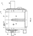
FIG. 2 illustrates a side view of the gearbox system ofFIG. 1 in accordance with an embodiment of the present invention. -
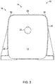
FIG. 3 schematically illustrates an end view of the gearbox system ofFIG. 1 in accordance with an embodiment of the present invention. -
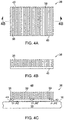
FIGS. 4A-4C schematically illustrate some aspects of a non-limiting example of a cooling fin panel for a gearbox system in accordance with an embodiment of the present invention. -
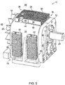
FIG. 5 illustrates some aspects of a non-limiting example of a gearbox system in accordance with an embodiment of the present invention. -
FIG. 6 illustrates some aspects of a non-limiting example of a gearbox system in accordance with an embodiment of the present invention. - For the purposes of promoting an understanding of the principles of the invention, reference will now be made to the embodiments illustrated in the drawings and specific language will be used to describe the same. It will nevertheless be understood that no limitation of the scope of the invention is thereby intended. Any alterations and further modifications in the described embodiments, and any further applications of the principles of the invention as described herein are contemplated as would normally occur to one skilled in the art to which the invention relates. Referring to
FIGS. 1-3 , some aspects of a non-limiting example of agearbox system 10 accordance with an embodiment of the present invention are illustrated. Gearboxsystem 10 includes agearbox 12. In one form, gearbox 12 is a gear reducer, i.e., a speed-reducing gearbox. In other embodiments,gearbox 12 may be a speed-increasing gearbox. In yetother embodiments gearbox 12 may be another type of gearbox. Gearbox 12 includes ahousing 14 havingexternal surface 16, a fan orimpeller 18, ashroud 20, aninput shaft 22 and anoutput shaft 24. In one form,housing 14 is a cast housing, e.g., a cast iron housing. In other embodiments,housing 14 may be an aluminum or other casting. In some embodiments,housing 14 may be a machined or welded housing. -
External surface 16 is employed for extracting heat fromgearbox 12 throughhousing 14, i.e., forcooling gearbox 12.External surface 16 has acontoured shape 26. Contouredshape 26 includes a plurality offlat portions 28, a plurality ofcurved portions 30, and a plurality ofcurved portions 32. Curvedportions 32 are more gently curved thancurved portions 30. - Fan or
impeller 18 is coupled toinput shaft 22, and is constructed to generate acooling airflow 34. Fan orimpeller 18 may be, for example, a radial or centrifugal fan and/or an axial fan, or an impeller. Shroud 20 is constructed to directcooling airflow 34 from fan orimpeller 18 overexternal surface 16, and over and/or through a plurality of cooling fins 38 (described below). - Gear reducers and other types of gearboxes may be thermally limited, due to internal power losses (e.g., gear churning, mesh, and bearing drag losses). The internal power losses generate heat, which drives up the temperature of the gearbox, which may adversely affect the life of the gearbox under some conditions, and which may limit the power density of the gearbox. In order to improve power density, e.g., of existing and of future gearbox designs, a scheme to provide or improve gearbox cooling may be employed as an add-on feature. Embodiments of the present invention include the use of add-on
cooling fin panels 36, which reduce the operating temperatures ofgearbox 12, which may permitgearbox 12 to transmit more power and/or torque, and which thus may increase the power density ofgearbox 12. Although cooling fins may be formed as part of a cast iron housing, cast fins typically have a low fin efficiency because the thermal conductivity of cast iron is low, e.g., compared to aluminum or copper. In addition, it may be undesirably difficult and cost prohibitive to manufacture the slender fins that are preferred using the standard casting processes used to form typical cast gearbox housings. Also, some customers prefer gearbox housings without fins. Thus, it is preferable to have add-on cooling fins so that the same gearbox housing may be used for customers who prefer gearbox housings with fins and for customers who prefer gearbox housings without fins, which may reduce the cost of the gearbox housing. - Referring also to
FIGS. 4A-4C ,gearbox system 10 includes a plurality of add-oncooling fin panels 36 affixed toexternal surface 16 ofhousing 14 ofgearbox 12. Eachcooling fin panel 36 includes a plurality ofcooling fins 38 extending from abase 40. In some embodiments,base 40 is defined by the largest dimension(s) ofcooling fin panels 36, in order to maximize heat transfer throughcooling fin panels 36.Cooling fins 38 are of a slender configuration that is unavailable with cast gearbox housings configurations.Cooling fin panels 36 are constructed to transfer heat fromexternal surface 16 ofhousing 14 by conduction, e.g., thoughbase 40, and to transfer heat to theenvironment 46 in whichgearbox 12 is located by convection, e.g., viacooling fins 38. -
Cooling fin panels 36 are referred to as "add-on" because they are added togearbox 12, e.g., subsequent to the casting or other manufacture ofhousing 14, and in some embodiments, subsequent to the manufacture ofgearbox 12; and because coolingfin panels 36 are formed to mate withhousing 14 and are not formed as part of or integral tohousing 14. In some embodiments, coolingfin panels 36 may be added togearbox 12 during the manufacture ofgearbox 12 or added prior to the delivery ofgearbox 12 to a customer or end-user. In some embodiments, coolingfin panels 36 may be added togearbox 12 by the customer or end-user. -
Cooling fin panels 36 are in thermal engagement withexternal surface 16, and are thermally and mechanically coupled toexternal surface 16. For example,base 40 is in contact withexternal surface 16 ofhousing 14 for transferring heat fromhousing 14 to eachcooling fin panel 36. In some embodiments, coolingfin panels 36 are constructed to match and engage thecontoured shape 26 ofhousing 14. For example,base 40 of coolingfin panels 36 may be formed to match and complement the contour of the correspondingflat portions 28, curvedportions 30, and/orcurved portions 32 ofhousing 14, e.g., in order to maximize effective thermal contact area betweencooling fin panels 36 andhousing 14. - Some embodiments also employ a
thermal coupling layer 44 disposed betweencooling fin panels 36 andexternal surface 16 ofhousing 14. Athermal coupling layer 44 is in contact with bothbase 40 of eachcooling fin panel 36 and withexternal surface 16 ofhousing 14.Thermal coupling layer 44 is constructed to thermally couple each respectivecooling fin panel 36 withhousing 14, and to enhance heat transfer fromhousing 14 to each respectivecooling fin panel 36. In some embodiments,thermal coupling layer 44 is constructed to increase thermal contact area betweenexternal surface 16 andbase 40 by filling in gaps betweenexternal surface 16 andbase 40, e.g., gaps stemming from manufacturing tolerances or other manufacturing variations that otherwise prevent 100% contact engagement betweenbase 40 andexternal surface 16. In some embodiments,thermal coupling layer 44 is also or alternatively constructed to increase thermal contact area betweenexternal surface 16 andbase 40 by filing in and compensating for surface variations or asperities associated with the surface roughness ofsurface 16 andbase 40.Thermal coupling layer 44 may be, for example, a thermal grease, a thermal paste, thermal contact pads and/or another layer or other structure constructed and operative to thermally couple coolingfin panels 36 withhousing 14, and to enhance conductive heat transfer fromhousing 14 to each respectivecooling fin panel 36, e.g., as described hereinabove. - Cooling
fin panels 36 are formed of a metallic material. Preferably, coolingfin panels 36 are formed of a material having a thermal conductivity as high as or higher than that of the material that formshousing 14. In one non-limiting example,housing 14 is formed of cast iron. In one non-limiting example, coolingfin panels 36 are made of aluminum, e.g., 6061-T6 aluminum. In other embodiments, coolingfin panels 36 may be made of copper or a copper and/or aluminum alloy or another metal or alloy. When made of aluminum, coolingfin panels 36 may be anodized, e.g., for improved convection and for abrasion resistance to dust and debris. Coolingfin panels 36 may be made by die-casting, extrusion, and/or may be made by water jetting or other machining/material removal processes. In some embodiments, coolingfin panels 36 may be in the form of folded sheet metal structures. - Preferably, cooling
fins 38 are slender, e.g., have a slender aspect ratio, with a pitch-to-height ratio between 0.05 and 0.6. More preferably, the pitch-to-height ratio is approximately 0.2. In other embodiments, coolingfins 38 may have one or more other pitch-to-height ratios. Coolingfins 38 may be rectangular, triangular, or may have another shape such as a pin or cylindrical shape. Coolingfins 38 may be, for example, smooth, or serrated. - In some embodiments, cooling
fin panels 36 are releasably attached tohousing 14 ofgearbox 12, in particular, toexternal surface 16 ofhousing 14. In one form, attachment features 42 may be constructed to affixcooling panels 36 tohousing 14 ofgearbox 12. In other embodiments, attachment features 42 may be constructed to releasably affix coolingfin panels 36 tohousing 14 ofgearbox 12. For example, in some embodiments, coolingfin panels 36 may be attached tohousing 14 via the use of attachment features 42 in the form of fasteners such as screws. In some embodiments, the fasteners may be unscrewed or otherwise uninstalled, allowing the removal of coolingfin panels 36 fromgearbox 12. In some embodiments, the fasteners or other attachment features 42 may be reusable. - Referring also to
FIGS. 5 and6 , in some embodiments, coolingfins 38 ofcooling fin panels 36 may be continuous from one side or end of each coolingfin panel 36 to the other, as illustrated inFIG. 5 . In other embodiments or may be segmented, e.g., each row of fins being subdivided or partitioned into a plurality of fin segments, for instance, fourfin segments FIG. 6 . The fin segments can also be staggered, i.e., the fin segments may be shifted slightly up or down during mounting so that the fins of one fin segment line up with the gaps in another fin segment. During the operation ofgearbox system 10, fan orimpeller 18 is rotated byshaft 22, and draws in air from theenvironment 46 in whichgearbox 12 is located, and generates coolingairflow 34. The air is drawn into, for example, an opening orinlet 48 inshroud 20.Shroud 20 directs cooling airflow over and/or through the coolingfins 38 ofcooling fin panels 36, extracting heat fromgearbox 12 via convection. In some embodiments, coolingfins 38 maybe shaped to enhance airflow over and/or throughcooling fins 38. Some embodiments may not include a fan orimpeller 18, in which case, the coolingfins 38 may be shaped to promote natural convection. - Embodiments of the present invention include a gearbox system, comprising: a gearbox having a housing, wherein the housing includes a surface; an add-on cooling fin panel in thermal engagement with the surface, wherein the cooling fin panel includes a plurality of cooling fins; and an attachment feature constructed to affix the cooling fin panel to the gearbox, wherein the cooling fin panel is constructed to transfer heat from the surface to the cooling fin panel by conduction; and wherein the cooling fin panel is configured to transfer heat to an environment in which the gearbox is located by convection.
- In a refinement, the surface has a contoured shape; and wherein the cooling fin panel is constructed to match and engage the contoured shape.
In another refinement, the cooling fin panel includes a plurality of cooling fins.
In yet another refinement, the gearbox system further comprises a thermal coupling layer disposed between the surface and the cooling fin panel.In still another refinement, the thermal coupling layer is a thermal grease or a thermal paste.
In yet still another embodiment, the attachment feature is a fastener constructed to affix the cooling fin panel to the housing. In a further embodiment, the cooling fin panel is formed of aluminum. In a yet further refinement, the aluminum is anodized. In a still further refinement, the cooling fins have a pitch-to-height ratio in the range of 0.05 and 0.6. In a yet still further refinement, the cooling fins are segmented.
In another refinement, the cooling fins are staggered. - Embodiments of the present invention include a gearbox system, comprising: a reducing gearbox having a housing and a shaft extending from the housing, wherein the housing includes a surface; a fan or impeller coupled to the shaft and constructed to generate a cooling airflow; an add-on cooling fin panel in thermal engagement with the surface, wherein the cooling fin panel includes a plurality of cooling fins; an attachment feature constructed to affix the cooling fin panel to the gearbox; and a shroud constructed to direct the cooling airflow from the fan or impeller over and/or through the plurality of cooling fins, wherein the cooling fin panel is constructed to transfer heat from the surface to the cooling fin panel by conduction; and wherein the cooling fin panel is configured to transfer heat to an environment in which the gearbox is located by convection.
In a refinement, the surface has a contoured shape; and wherein the cooling fin panel is constructed to match and engage the contoured shape.
In another refinement, the cooling fin panel includes a plurality of cooling fins.
In yet another refinement, the gearbox system further comprises a thermal coupling layer disposed between the surface and the cooling fin panel.
In still another refinement, the thermal coupling layer is a thermal grease or a thermal paste.In yet still another refinement, the attachment feature is a fastener constructed to affix the cooling fin panel to the housing.
In a further refinement, wherein the cooling fin panel is formed of aluminum.
In a yet further refinement, the aluminum is anodized.
In a still further refinement, the cooling fins have a pitch-to-height ratio in the range of 0.05 and 0.6.In a yet still further refinement, the cooling fins are segmented. - While the invention has been illustrated and described in detail in the drawings and foregoing description, the same is to be considered as illustrative and not restrictive in character, it being understood that only the preferred embodiments have been shown and described and that all changes and modifications that come within the spirit of the inventions are desired to be protected. It should be understood that while the use of words such as preferable, preferably, preferred or more preferred utilized in the description above indicate that the feature so described may be more desirable, it nonetheless may not be necessary and embodiments lacking the same may be contemplated as within the scope of the invention, the scope being defined by the claims that follow. In reading the claims, it is intended that when words such as "a," "an," "at least one," or "at least one portion" are used there is no intention to limit the claim to only one item unless specifically stated to the contrary in the claim. When the language "at least a portion" and/or "a portion" is used the item can include a portion and/or the entire item unless specifically stated to the contrary. Unless specified or limited otherwise, the terms "mounted," "connected," "supported," and "coupled" and variations thereof are used broadly and encompass both direct and indirect mountings, connections, supports, and couplings. Further, "connected" and "coupled" are not restricted to physical or mechanical connections or couplings.
Claims (14)
- A gearbox system, comprising:a gearbox having a housing, wherein the housing includes a surface;an add-on cooling fin panel in thermal engagement with the surface, wherein the cooling fin panel includes a plurality of cooling fins; andan attachment feature constructed to affix the cooling fin panel to the gearbox,wherein the cooling fin panel is constructed to transfer heat from the surface to the cooling fin panel by conduction; andwherein the cooling fin panel is configured to transfer heat to an environment in which the gearbox is located by convection.
- The gearbox system of claim 1, wherein the cooling fins have a pitch-to-height ratio in the range of 0.05 and 0.6.
- The gearbox system of claim 1, wherein the cooling fins are segmented.
- A gearbox system, comprising:a gear reducer gearbox having a housing and a shaft extending from the housing, wherein the housing includes a surface;a fan or impeller coupled to the shaft and constructed to generate a cooling airflow;an add-on cooling fin panel in thermal engagement with the surface, wherein the cooling fin panel includes a plurality of cooling fins;an attachment feature constructed to affix the cooling fin panel to the gearbox; anda shroud constructed to direct the cooling airflow from the fan or impeller over and/or through the plurality of cooling fins,wherein the cooling fin panel is constructed to transfer heat from the surface to the cooling fin panel by conduction; andwherein the cooling fin panel is configured to transfer heat to an environment in which the gearbox is located by convection.
- The gearbox system of claim 1 or 4, wherein the surface has a contoured shape; and wherein the cooling fin panel is constructed to match and engage the contoured shape.
- The gearbox system of claim 1 or 4, wherein the cooling fin panel includes a plurality of cooling fins.
- The gearbox system of claim 1 or 4, further comprising a thermal coupling layer disposed between the surface and the cooling fin panel.
- The gearbox system of claim 1 or 4, wherein the thermal coupling layer is a thermal grease or a thermal paste.
- The gearbox system of claim 1 or 4, wherein the attachment feature is a fastener constructed to affix the cooling fin panel to the housing.
- The gearbox system of claim 1 or 4, wherein the cooling fin panel is formed of aluminum.
- The gearbox system of claim 10, wherein the aluminum is anodized.
- The gearbox system of claim 4, wherein the cooling fins have a pitch-to-height ratio in the range of 0.05 and 0.6.
- The gearbox system of claim 4, wherein the cooling fins are segmented.
- The gearbox system of claim 4, wherein the cooling fins are staggered.
Applications Claiming Priority (1)
| Application Number | Priority Date | Filing Date | Title |
|---|---|---|---|
| US15/994,562 US10458534B1 (en) | 2018-05-31 | 2018-05-31 | Gearbox system with add-on cooling fin panels |
Publications (2)
| Publication Number | Publication Date |
|---|---|
| EP3575639A1 true EP3575639A1 (en) | 2019-12-04 |
| EP3575639B1 EP3575639B1 (en) | 2021-09-08 |
Family
ID=66685450
Family Applications (1)
| Application Number | Title | Priority Date | Filing Date |
|---|---|---|---|
| EP19177684.8A Not-in-force EP3575639B1 (en) | 2018-05-31 | 2019-05-31 | Gearbox system with add-on cooling fin panels |
Country Status (2)
| Country | Link |
|---|---|
| US (1) | US10458534B1 (en) |
| EP (1) | EP3575639B1 (en) |
Families Citing this family (7)
| Publication number | Priority date | Publication date | Assignee | Title |
|---|---|---|---|---|
| US11466768B2 (en) | 2018-12-31 | 2022-10-11 | Abb Schweiz Ag | Methods and systems for cooling transmissions |
| US11287025B2 (en) | 2018-12-31 | 2022-03-29 | Abb Schweiz Ag | Cooling units for transmissions |
| CN113614413B (en) * | 2019-03-26 | 2024-02-09 | 索尤若驱动有限及两合公司 | Speed reducer with fan device |
| US11174937B2 (en) * | 2019-09-23 | 2021-11-16 | Abb Schweiz Ag | Speed reducer cooling fins and method of manufacturing |
| WO2021087938A1 (en) * | 2019-11-08 | 2021-05-14 | 南京金崎新能源动力研究院有限公司 | Heat dissipation structure for speed reducer |
| CN112178171B (en) * | 2020-01-06 | 2021-11-23 | 林建国 | Transmission with simple structure and automatic gear shifting device |
| CN113202914A (en) * | 2021-03-26 | 2021-08-03 | 南京德伦重载齿轮箱有限公司 | Safe assembly form of steel tube mill angle gear box and use method thereof |
Citations (4)
| Publication number | Priority date | Publication date | Assignee | Title |
|---|---|---|---|---|
| EP2263025B1 (en) * | 2008-04-04 | 2012-11-14 | SEW-EURODRIVE GmbH & Co. KG | Adapter, transmission and drive |
| EP2687757A1 (en) * | 2006-05-03 | 2014-01-22 | SEW-EURODRIVE GmbH & Co. KG | Cooper for transmission, transmission with cooling device, modular system of transmission cooling devices, and type series of transmissions |
| US8967334B2 (en) * | 2009-03-25 | 2015-03-03 | Sew-Eurodrive Gmbh & Co. Kg | Gear unit at least partially filled with oil |
| DE102015011163A1 (en) * | 2015-04-13 | 2016-10-13 | Sew-Eurodrive Gmbh & Co Kg | Transmission, comprising a shaft, a flange and a housing part |
Family Cites Families (26)
| Publication number | Priority date | Publication date | Assignee | Title |
|---|---|---|---|---|
| US1991618A (en) * | 1930-11-03 | 1935-02-19 | Borg Warner | Radiating type oil pan for internal combustion engines |
| US2583751A (en) * | 1948-10-27 | 1952-01-29 | Falk Corp | Air-cooled gear set |
| DE1283404B (en) * | 1967-02-16 | 1968-11-21 | Philips Patentverwertung Gmbh | Radiator assembly for contact cooling for electrical discharge tubes |
| US3550678A (en) * | 1969-04-01 | 1970-12-29 | United Aircraft Prod | Surface radiator |
| US4022272A (en) * | 1975-11-14 | 1977-05-10 | Chester O. Houston, Jr. | Transmission fluid heat radiator |
| WO1991004427A1 (en) * | 1989-09-23 | 1991-04-04 | Zahnradfabrik Friedrichshafen Ag | Housing for a gearbox |
| US5193415A (en) * | 1991-06-04 | 1993-03-16 | Bruno's Automotive Products Inc. | Continuous radial shield for automatic transmission |
| US5816320A (en) * | 1997-01-10 | 1998-10-06 | J.I.T. Engineering, Inc. | Radiator fin construction |
| US6425293B1 (en) * | 1999-03-13 | 2002-07-30 | Textron Systems Corporation | Sensor plug |
| JP2001098915A (en) * | 1999-09-29 | 2001-04-10 | Fuji Heavy Ind Ltd | Splash lubrication engine |
| FR2807828B1 (en) * | 2000-04-17 | 2002-07-12 | Nordon Cryogenie Snc | CORRUGATED WING WITH PARTIAL OFFSET FOR PLATE HEAT EXCHANGER AND CORRESPONDING PLATE HEAT EXCHANGER |
| JP3757765B2 (en) * | 2000-06-23 | 2006-03-22 | いすゞ自動車株式会社 | Transmission case structure |
| US6919504B2 (en) * | 2002-12-19 | 2005-07-19 | 3M Innovative Properties Company | Flexible heat sink |
| US20060035413A1 (en) * | 2004-01-13 | 2006-02-16 | Cookson Electronics, Inc. | Thermal protection for electronic components during processing |
| DE102004022863B4 (en) * | 2004-05-06 | 2010-08-05 | Sew-Eurodrive Gmbh & Co. Kg | transmission |
| US8410350B2 (en) * | 2006-12-11 | 2013-04-02 | Ns Acquisition Llc | Modular solar panels with heat exchange |
| DE102009014317A1 (en) * | 2009-03-25 | 2010-10-07 | Sew-Eurodrive Gmbh & Co. Kg | transmission |
| DE102009014315B4 (en) * | 2009-03-25 | 2018-01-25 | Sew-Eurodrive Gmbh & Co Kg | transmission |
| DE102009014316B4 (en) * | 2009-03-25 | 2019-03-14 | Sew-Eurodrive Gmbh & Co Kg | transmission |
| US9599406B2 (en) * | 2010-01-27 | 2017-03-21 | Rexnord Industries, Llc | Transmission having a fluid cooling shroud |
| JP6063288B2 (en) * | 2013-02-15 | 2017-01-18 | 住友重機械工業株式会社 | Power transmission device |
| US10058008B2 (en) * | 2013-10-29 | 2018-08-21 | Tai-Her Yang | Temperature control system having adjacently-installed temperature equalizer and heat transfer fluid and application device thereof |
| US20150289850A1 (en) * | 2014-04-15 | 2015-10-15 | Tyco Electronics Corporation | Heat Dissipation Assemblies |
| ES2824260T3 (en) * | 2015-04-23 | 2021-05-11 | Flender Gmbh | Air baffle for a transmission and transmission with an air baffle |
| DE102015215410A1 (en) * | 2015-08-12 | 2017-02-16 | Mahle International Gmbh | Stacking plate heat exchanger, in particular intercooler |
| EP3359902B2 (en) * | 2015-10-08 | 2023-06-28 | Linde GmbH | Method for manufacturing a lamella and a plate heat exchanger with a lamella manufactured by such a method |
-
2018
- 2018-05-31 US US15/994,562 patent/US10458534B1/en not_active Expired - Fee Related
-
2019
- 2019-05-31 EP EP19177684.8A patent/EP3575639B1/en not_active Not-in-force
Patent Citations (4)
| Publication number | Priority date | Publication date | Assignee | Title |
|---|---|---|---|---|
| EP2687757A1 (en) * | 2006-05-03 | 2014-01-22 | SEW-EURODRIVE GmbH & Co. KG | Cooper for transmission, transmission with cooling device, modular system of transmission cooling devices, and type series of transmissions |
| EP2263025B1 (en) * | 2008-04-04 | 2012-11-14 | SEW-EURODRIVE GmbH & Co. KG | Adapter, transmission and drive |
| US8967334B2 (en) * | 2009-03-25 | 2015-03-03 | Sew-Eurodrive Gmbh & Co. Kg | Gear unit at least partially filled with oil |
| DE102015011163A1 (en) * | 2015-04-13 | 2016-10-13 | Sew-Eurodrive Gmbh & Co Kg | Transmission, comprising a shaft, a flange and a housing part |
Also Published As
| Publication number | Publication date |
|---|---|
| US10458534B1 (en) | 2019-10-29 |
| EP3575639B1 (en) | 2021-09-08 |
Similar Documents
| Publication | Publication Date | Title |
|---|---|---|
| US10458534B1 (en) | Gearbox system with add-on cooling fin panels | |
| JP5336618B2 (en) | Gas turbine engine assembly | |
| US20170108291A1 (en) | Plate-like air-cooled engine surface cooler with fluid channel and varying fin geometry | |
| CN208158305U (en) | A kind of novel motor shell | |
| US20210088123A1 (en) | Speed reducer cooling fins and method of manufacturing | |
| CN111622810B (en) | Connection device, gas turbine engine, connection piece and turbine outer ring | |
| CN114337116B (en) | Motor with rotor cooling structure and application thereof | |
| EP2595183B1 (en) | Heat dissipation module | |
| US9754857B2 (en) | Folded fin heat transfer device | |
| CN113098177A (en) | Stator heat dissipation structure for inner rotor motor, inner rotor motor and ducted fan | |
| CN118188055A (en) | Aeroengine director blade structure and aeroengine | |
| CN107172854A (en) | Vehicle-mounted integrated controller cooling system based on plate-fin heat pipe radiator | |
| EP4583648A1 (en) | Heat exchange system and electronic device | |
| CN214314874U (en) | Liquid cooling motor | |
| US20200018558A1 (en) | Mechanical System with Cooling Apparatus | |
| CN221767694U (en) | Heat dissipation structure of permanent magnet synchronous motor rotor assembly | |
| CN211202639U (en) | Bearing internal circulation cooling structure in cooling fan | |
| CN119134753A (en) | Heat dissipation end cover and motor | |
| CN224083923U (en) | Detachable aluminum radiator | |
| RU241141U1 (en) | Gas turbine engine hollow shaft support unit | |
| CN223842190U (en) | Optical module components for servers and servers | |
| CN216362272U (en) | Motor heat dissipation casing | |
| CN216555006U (en) | Needle roller bearing with shell | |
| CN216530968U (en) | Three-phase direct current brushless motor applied to high-temperature environment | |
| CN220068077U (en) | Combined type radiating fin connecting structure |
Legal Events
| Date | Code | Title | Description |
|---|---|---|---|
| PUAI | Public reference made under article 153(3) epc to a published international application that has entered the european phase |
Free format text: ORIGINAL CODE: 0009012 |
|
| STAA | Information on the status of an ep patent application or granted ep patent |
Free format text: STATUS: REQUEST FOR EXAMINATION WAS MADE |
|
| 17P | Request for examination filed |
Effective date: 20190531 |
|
| AK | Designated contracting states |
Kind code of ref document: A1 Designated state(s): AL AT BE BG CH CY CZ DE DK EE ES FI FR GB GR HR HU IE IS IT LI LT LU LV MC MK MT NL NO PL PT RO RS SE SI SK SM TR |
|
| AX | Request for extension of the european patent |
Extension state: BA ME |
|
| STAA | Information on the status of an ep patent application or granted ep patent |
Free format text: STATUS: EXAMINATION IS IN PROGRESS |
|
| 17Q | First examination report despatched |
Effective date: 20210208 |
|
| GRAP | Despatch of communication of intention to grant a patent |
Free format text: ORIGINAL CODE: EPIDOSNIGR1 |
|
| STAA | Information on the status of an ep patent application or granted ep patent |
Free format text: STATUS: GRANT OF PATENT IS INTENDED |
|
| INTG | Intention to grant announced |
Effective date: 20210528 |
|
| GRAS | Grant fee paid |
Free format text: ORIGINAL CODE: EPIDOSNIGR3 |
|
| GRAA | (expected) grant |
Free format text: ORIGINAL CODE: 0009210 |
|
| STAA | Information on the status of an ep patent application or granted ep patent |
Free format text: STATUS: THE PATENT HAS BEEN GRANTED |
|
| AK | Designated contracting states |
Kind code of ref document: B1 Designated state(s): AL AT BE BG CH CY CZ DE DK EE ES FI FR GB GR HR HU IE IS IT LI LT LU LV MC MK MT NL NO PL PT RO RS SE SI SK SM TR |
|
| REG | Reference to a national code |
Ref country code: GB Ref legal event code: FG4D |
|
| REG | Reference to a national code |
Ref country code: CH Ref legal event code: EP Ref country code: AT Ref legal event code: REF Ref document number: 1428870 Country of ref document: AT Kind code of ref document: T Effective date: 20210915 |
|
| REG | Reference to a national code |
Ref country code: DE Ref legal event code: R096 Ref document number: 602019007467 Country of ref document: DE |
|
| REG | Reference to a national code |
Ref country code: IE Ref legal event code: FG4D |
|
| REG | Reference to a national code |
Ref country code: LT Ref legal event code: MG9D |
|
| REG | Reference to a national code |
Ref country code: NL Ref legal event code: MP Effective date: 20210908 |
|
| PG25 | Lapsed in a contracting state [announced via postgrant information from national office to epo] |
Ref country code: ES Free format text: LAPSE BECAUSE OF FAILURE TO SUBMIT A TRANSLATION OF THE DESCRIPTION OR TO PAY THE FEE WITHIN THE PRESCRIBED TIME-LIMIT Effective date: 20210908 Ref country code: FI Free format text: LAPSE BECAUSE OF FAILURE TO SUBMIT A TRANSLATION OF THE DESCRIPTION OR TO PAY THE FEE WITHIN THE PRESCRIBED TIME-LIMIT Effective date: 20210908 Ref country code: RS Free format text: LAPSE BECAUSE OF FAILURE TO SUBMIT A TRANSLATION OF THE DESCRIPTION OR TO PAY THE FEE WITHIN THE PRESCRIBED TIME-LIMIT Effective date: 20210908 Ref country code: SE Free format text: LAPSE BECAUSE OF FAILURE TO SUBMIT A TRANSLATION OF THE DESCRIPTION OR TO PAY THE FEE WITHIN THE PRESCRIBED TIME-LIMIT Effective date: 20210908 Ref country code: LT Free format text: LAPSE BECAUSE OF FAILURE TO SUBMIT A TRANSLATION OF THE DESCRIPTION OR TO PAY THE FEE WITHIN THE PRESCRIBED TIME-LIMIT Effective date: 20210908 Ref country code: BG Free format text: LAPSE BECAUSE OF FAILURE TO SUBMIT A TRANSLATION OF THE DESCRIPTION OR TO PAY THE FEE WITHIN THE PRESCRIBED TIME-LIMIT Effective date: 20211208 Ref country code: NO Free format text: LAPSE BECAUSE OF FAILURE TO SUBMIT A TRANSLATION OF THE DESCRIPTION OR TO PAY THE FEE WITHIN THE PRESCRIBED TIME-LIMIT Effective date: 20211208 Ref country code: HR Free format text: LAPSE BECAUSE OF FAILURE TO SUBMIT A TRANSLATION OF THE DESCRIPTION OR TO PAY THE FEE WITHIN THE PRESCRIBED TIME-LIMIT Effective date: 20210908 |
|
| REG | Reference to a national code |
Ref country code: AT Ref legal event code: MK05 Ref document number: 1428870 Country of ref document: AT Kind code of ref document: T Effective date: 20210908 |
|
| PG25 | Lapsed in a contracting state [announced via postgrant information from national office to epo] |
Ref country code: LV Free format text: LAPSE BECAUSE OF FAILURE TO SUBMIT A TRANSLATION OF THE DESCRIPTION OR TO PAY THE FEE WITHIN THE PRESCRIBED TIME-LIMIT Effective date: 20210908 Ref country code: GR Free format text: LAPSE BECAUSE OF FAILURE TO SUBMIT A TRANSLATION OF THE DESCRIPTION OR TO PAY THE FEE WITHIN THE PRESCRIBED TIME-LIMIT Effective date: 20211209 |
|
| PG25 | Lapsed in a contracting state [announced via postgrant information from national office to epo] |
Ref country code: AT Free format text: LAPSE BECAUSE OF FAILURE TO SUBMIT A TRANSLATION OF THE DESCRIPTION OR TO PAY THE FEE WITHIN THE PRESCRIBED TIME-LIMIT Effective date: 20210908 |
|
| PG25 | Lapsed in a contracting state [announced via postgrant information from national office to epo] |
Ref country code: IS Free format text: LAPSE BECAUSE OF FAILURE TO SUBMIT A TRANSLATION OF THE DESCRIPTION OR TO PAY THE FEE WITHIN THE PRESCRIBED TIME-LIMIT Effective date: 20220108 Ref country code: SM Free format text: LAPSE BECAUSE OF FAILURE TO SUBMIT A TRANSLATION OF THE DESCRIPTION OR TO PAY THE FEE WITHIN THE PRESCRIBED TIME-LIMIT Effective date: 20210908 Ref country code: SK Free format text: LAPSE BECAUSE OF FAILURE TO SUBMIT A TRANSLATION OF THE DESCRIPTION OR TO PAY THE FEE WITHIN THE PRESCRIBED TIME-LIMIT Effective date: 20210908 Ref country code: RO Free format text: LAPSE BECAUSE OF FAILURE TO SUBMIT A TRANSLATION OF THE DESCRIPTION OR TO PAY THE FEE WITHIN THE PRESCRIBED TIME-LIMIT Effective date: 20210908 Ref country code: PT Free format text: LAPSE BECAUSE OF FAILURE TO SUBMIT A TRANSLATION OF THE DESCRIPTION OR TO PAY THE FEE WITHIN THE PRESCRIBED TIME-LIMIT Effective date: 20220110 Ref country code: PL Free format text: LAPSE BECAUSE OF FAILURE TO SUBMIT A TRANSLATION OF THE DESCRIPTION OR TO PAY THE FEE WITHIN THE PRESCRIBED TIME-LIMIT Effective date: 20210908 Ref country code: NL Free format text: LAPSE BECAUSE OF FAILURE TO SUBMIT A TRANSLATION OF THE DESCRIPTION OR TO PAY THE FEE WITHIN THE PRESCRIBED TIME-LIMIT Effective date: 20210908 Ref country code: EE Free format text: LAPSE BECAUSE OF FAILURE TO SUBMIT A TRANSLATION OF THE DESCRIPTION OR TO PAY THE FEE WITHIN THE PRESCRIBED TIME-LIMIT Effective date: 20210908 Ref country code: CZ Free format text: LAPSE BECAUSE OF FAILURE TO SUBMIT A TRANSLATION OF THE DESCRIPTION OR TO PAY THE FEE WITHIN THE PRESCRIBED TIME-LIMIT Effective date: 20210908 Ref country code: AL Free format text: LAPSE BECAUSE OF FAILURE TO SUBMIT A TRANSLATION OF THE DESCRIPTION OR TO PAY THE FEE WITHIN THE PRESCRIBED TIME-LIMIT Effective date: 20210908 |
|
| REG | Reference to a national code |
Ref country code: DE Ref legal event code: R097 Ref document number: 602019007467 Country of ref document: DE |
|
| PLBE | No opposition filed within time limit |
Free format text: ORIGINAL CODE: 0009261 |
|
| STAA | Information on the status of an ep patent application or granted ep patent |
Free format text: STATUS: NO OPPOSITION FILED WITHIN TIME LIMIT |
|
| PG25 | Lapsed in a contracting state [announced via postgrant information from national office to epo] |
Ref country code: DK Free format text: LAPSE BECAUSE OF FAILURE TO SUBMIT A TRANSLATION OF THE DESCRIPTION OR TO PAY THE FEE WITHIN THE PRESCRIBED TIME-LIMIT Effective date: 20210908 |
|
| PGFP | Annual fee paid to national office [announced via postgrant information from national office to epo] |
Ref country code: DE Payment date: 20220519 Year of fee payment: 4 |
|
| 26N | No opposition filed |
Effective date: 20220609 |
|
| PG25 | Lapsed in a contracting state [announced via postgrant information from national office to epo] |
Ref country code: SI Free format text: LAPSE BECAUSE OF FAILURE TO SUBMIT A TRANSLATION OF THE DESCRIPTION OR TO PAY THE FEE WITHIN THE PRESCRIBED TIME-LIMIT Effective date: 20210908 |
|
| REG | Reference to a national code |
Ref country code: CH Ref legal event code: PL |
|
| REG | Reference to a national code |
Ref country code: BE Ref legal event code: MM Effective date: 20220531 |
|
| PG25 | Lapsed in a contracting state [announced via postgrant information from national office to epo] |
Ref country code: MC Free format text: LAPSE BECAUSE OF FAILURE TO SUBMIT A TRANSLATION OF THE DESCRIPTION OR TO PAY THE FEE WITHIN THE PRESCRIBED TIME-LIMIT Effective date: 20210908 Ref country code: LU Free format text: LAPSE BECAUSE OF NON-PAYMENT OF DUE FEES Effective date: 20220531 Ref country code: LI Free format text: LAPSE BECAUSE OF NON-PAYMENT OF DUE FEES Effective date: 20220531 Ref country code: IT Free format text: LAPSE BECAUSE OF FAILURE TO SUBMIT A TRANSLATION OF THE DESCRIPTION OR TO PAY THE FEE WITHIN THE PRESCRIBED TIME-LIMIT Effective date: 20210908 Ref country code: CH Free format text: LAPSE BECAUSE OF NON-PAYMENT OF DUE FEES Effective date: 20220531 |
|
| REG | Reference to a national code |
Ref country code: DE Ref legal event code: R082 Ref document number: 602019007467 Country of ref document: DE Representative=s name: MAIWALD GMBH, DE |
|
| PG25 | Lapsed in a contracting state [announced via postgrant information from national office to epo] |
Ref country code: IE Free format text: LAPSE BECAUSE OF NON-PAYMENT OF DUE FEES Effective date: 20220531 Ref country code: FR Free format text: LAPSE BECAUSE OF NON-PAYMENT OF DUE FEES Effective date: 20220531 |
|
| PG25 | Lapsed in a contracting state [announced via postgrant information from national office to epo] |
Ref country code: BE Free format text: LAPSE BECAUSE OF NON-PAYMENT OF DUE FEES Effective date: 20220531 |
|
| REG | Reference to a national code |
Ref country code: DE Ref legal event code: R119 Ref document number: 602019007467 Country of ref document: DE |
|
| GBPC | Gb: european patent ceased through non-payment of renewal fee |
Effective date: 20230531 |
|
| PG25 | Lapsed in a contracting state [announced via postgrant information from national office to epo] |
Ref country code: HU Free format text: LAPSE BECAUSE OF FAILURE TO SUBMIT A TRANSLATION OF THE DESCRIPTION OR TO PAY THE FEE WITHIN THE PRESCRIBED TIME-LIMIT; INVALID AB INITIO Effective date: 20190531 |
|
| PG25 | Lapsed in a contracting state [announced via postgrant information from national office to epo] |
Ref country code: MK Free format text: LAPSE BECAUSE OF FAILURE TO SUBMIT A TRANSLATION OF THE DESCRIPTION OR TO PAY THE FEE WITHIN THE PRESCRIBED TIME-LIMIT Effective date: 20210908 Ref country code: DE Free format text: LAPSE BECAUSE OF NON-PAYMENT OF DUE FEES Effective date: 20231201 Ref country code: CY Free format text: LAPSE BECAUSE OF FAILURE TO SUBMIT A TRANSLATION OF THE DESCRIPTION OR TO PAY THE FEE WITHIN THE PRESCRIBED TIME-LIMIT Effective date: 20210908 Ref country code: GB Free format text: LAPSE BECAUSE OF NON-PAYMENT OF DUE FEES Effective date: 20230531 |
|
| PG25 | Lapsed in a contracting state [announced via postgrant information from national office to epo] |
Ref country code: TR Free format text: LAPSE BECAUSE OF FAILURE TO SUBMIT A TRANSLATION OF THE DESCRIPTION OR TO PAY THE FEE WITHIN THE PRESCRIBED TIME-LIMIT Effective date: 20210908 |
|
| PG25 | Lapsed in a contracting state [announced via postgrant information from national office to epo] |
Ref country code: MT Free format text: LAPSE BECAUSE OF FAILURE TO SUBMIT A TRANSLATION OF THE DESCRIPTION OR TO PAY THE FEE WITHIN THE PRESCRIBED TIME-LIMIT Effective date: 20210908 |