EP3575564A1 - Intake air delivery system - Google Patents
Intake air delivery system Download PDFInfo
- Publication number
- EP3575564A1 EP3575564A1 EP19163575.4A EP19163575A EP3575564A1 EP 3575564 A1 EP3575564 A1 EP 3575564A1 EP 19163575 A EP19163575 A EP 19163575A EP 3575564 A1 EP3575564 A1 EP 3575564A1
- Authority
- EP
- European Patent Office
- Prior art keywords
- valve
- intake
- seat ring
- engine
- valve seat
- Prior art date
- Legal status (The legal status is an assumption and is not a legal conclusion. Google has not performed a legal analysis and makes no representation as to the accuracy of the status listed.)
- Granted
Links
Images


Classifications
-
- F—MECHANICAL ENGINEERING; LIGHTING; HEATING; WEAPONS; BLASTING
- F01—MACHINES OR ENGINES IN GENERAL; ENGINE PLANTS IN GENERAL; STEAM ENGINES
- F01L—CYCLICALLY OPERATING VALVES FOR MACHINES OR ENGINES
- F01L3/00—Lift-valve, i.e. cut-off apparatus with closure members having at least a component of their opening and closing motion perpendicular to the closing faces; Parts or accessories thereof
- F01L3/06—Valve members or valve-seats with means for guiding or deflecting the medium controlled thereby, e.g. producing a rotary motion of the drawn-in cylinder charge
-
- F—MECHANICAL ENGINEERING; LIGHTING; HEATING; WEAPONS; BLASTING
- F02—COMBUSTION ENGINES; HOT-GAS OR COMBUSTION-PRODUCT ENGINE PLANTS
- F02B—INTERNAL-COMBUSTION PISTON ENGINES; COMBUSTION ENGINES IN GENERAL
- F02B31/00—Modifying induction systems for imparting a rotation to the charge in the cylinder
- F02B31/08—Modifying induction systems for imparting a rotation to the charge in the cylinder having multiple air inlets
-
- Y—GENERAL TAGGING OF NEW TECHNOLOGICAL DEVELOPMENTS; GENERAL TAGGING OF CROSS-SECTIONAL TECHNOLOGIES SPANNING OVER SEVERAL SECTIONS OF THE IPC; TECHNICAL SUBJECTS COVERED BY FORMER USPC CROSS-REFERENCE ART COLLECTIONS [XRACs] AND DIGESTS
- Y02—TECHNOLOGIES OR APPLICATIONS FOR MITIGATION OR ADAPTATION AGAINST CLIMATE CHANGE
- Y02T—CLIMATE CHANGE MITIGATION TECHNOLOGIES RELATED TO TRANSPORTATION
- Y02T10/00—Road transport of goods or passengers
- Y02T10/10—Internal combustion engine [ICE] based vehicles
- Y02T10/12—Improving ICE efficiencies
Definitions
- the present disclosure relates to an intake air delivery system. More particularly, the present disclosure relates to the intake air delivery system associated with an internal combustion engine.
- An internal combustion engine such as a natural gas powered engine, for example, may introduce intake air or a charge air mixture into a cylinder thereof via an intake valve.
- the intake valve may lift with respect to a valve seat in order to provide a varying valve gap for introduction of the intake air or the charge air mixture into the cylinder.
- a flow separation may form in the intake air or the charge air mixture flowing through the valve gap.
- the flow separation may be formed due to deflection of the intake air or the charge air mixture by an edge of a valve seat or a valve seat ring adjacent to the valve gap.
- the flow separation may, in turn, result in formation of a region of increased turbulence and backflow in the valve gap. This region may reduce an effective area of the valve gap resulting in reduced amount of the intake air or the charge air mixture flowing through the valve gap, in turn, reducing performance of the engine.
- U.S. Patent Number 5,074,256 describes a lubricating system for a valve seat of an internal combustion engine.
- the system produces a lubricant oil film on the valve seat of a seat ring.
- At least a part of the seat ring providing a valve seat surface is made of a porous material readily containing lubricant oil.
- An outer cylindrical surface of the seat ring is formed with an annular groove along its circumferential direction.
- a cylinder head to which the seat ring is fastened is formed with an oil passage for feeding lubricant oil to the groove. Feeding of the lubricant oil through the oil passage to the groove causes the valve seat surface to contain lubricant oil.
- the lubricant oil thus contained produces a lubricant oil film on the valve seat surface, which prevents wear in a valve head and the valve seat surface.
- an intake air delivery system for an engine includes a valve seat ring.
- the intake air delivery system includes an intake valve provided in association with the valve seat ring.
- the intake valve is adapted to contact the valve seat ring in a closed position of the intake valve.
- the intake valve is also adapted to provide a valve gap with respect to the valve seat ring in an open position of the intake valve.
- the intake air delivery system also includes at least one bore provided in the valve seat ring.
- the at least one bore is provided in selective fluid communication with the valve gap.
- the intake air delivery system further includes a conduit provided in fluid communication with the at least one bore and a vacuum pump. Each of the conduit and the at least one bore is adapted to provide a suction pressure of the vacuum pump to a portion of the valve gap adjacent to the valve seat ring.
- an engine in another aspect of the present disclosure, includes an engine block and a cylinder head mounted on the engine block.
- the engine also includes a plurality of cylinders provided in the engine block.
- the engine further includes an intake air delivery system.
- the intake air delivery system includes at least one valve seat ring provided in association with each of the plurality of cylinders.
- the intake air delivery system includes an intake valve provided in association with the at least one valve seat ring.
- the intake valve is adapted to contact the at least one valve seat ring in a closed position of the intake valve.
- the intake valve is also adapted to provide a valve gap with respect to the at least one valve seat ring in an open position of the intake valve.
- the intake air delivery system also includes at least one bore provided in the at least one valve seat ring.
- the at least one bore is provided in selective fluid communication with the valve gap.
- the intake air delivery system further includes a conduit provided in fluid communication with the at least one bore and a vacuum pump. Each of the conduit and the at least one bore is adapted to provide a suction pressure of the vacuum pump to a portion of the valve gap adjacent to the at least one valve seat ring.
- a method for limiting a flow separation and a backflow of an intake air through an intake valve of an engine includes providing at least one bore in a valve seat ring associated with the intake valve. The method includes providing fluid communication between the at least one bore and a valve gap associated with the intake valve in an open position of the intake valve. The method includes providing a flow of the intake air through the valve gap. The method includes forming the flow separation and the backflow of the intake air adjacent to the valve seat ring. The method also includes providing a suction pressure in the valve gap adjacent to the valve seat ring through the at least one bore. The method further includes limiting the flow separation and the backflow of the intake air using the suction pressure.
- the engine 100 is an internal combustion engine powered by any fuel known in the art, such as natural gas, gasoline, and/or a combination thereof.
- the engine 100 may be associated with a machine (not shown) including, but not limited to, a locomotive, a marine vessel, a land vehicle, and a power generator.
- the engine 100 and/or the machine may be employed in any industry including, but not limited to, construction, agriculture, forestry, mining, transportation, waste management, aviation, marine, material handling, and power generation.
- the engine 100 includes an engine block 102.
- the engine block 102 may include one or more cylinders 302 (shown in FIG. 3 ) provided therein.
- the cylinders 302 may be arranged in any configuration including, but not limited to, an inline, radial, and "V", among others.
- Each of the cylinders 302 is adapted to receive a piston (not shown) therein.
- the engine 100 also includes a cylinder head 104 mounted on the engine block 102.
- the cylinder head 104 may house one or more components and/or systems (not shown) of the engine 100, such as an intake manifold, an exhaust manifold, a valve train, and sensors, among others.
- the engine 100 may include various other components and/or systems (not shown) including, but not limited to, a crankcase, a fuel system, a cooling system, a lubrication system, a turbocharger, a supercharger, an exhaust gas recirculation system, and peripheries, among others.
- valve seat ring 206 is adapted to be disposed in the cylinder head 104. It should be noted that the engine 100 may include one or more valve seat rings 206 associated with each of the cylinders 302, based on application requirements.
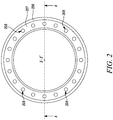
- the valve seat ring 206 includes a substantially circular configuration defining an axis X-X' thereof.
- the valve seat ring 206 includes a circumferential groove 207 provided thereon.
- the valve seat ring 206 also includes a plurality of ring bores 208 provided thereon in association with the circumferential groove 207.
- Each of the plurality of ring bores 208 is disposed circumferentially on the valve seat ring 206 and spaced apart with respect to one another.
- each of the plurality of ring bores 208 is disposed substantially parallel with respect to the axis X-X'. In other embodiments, one or more of the plurality of ring bores 208 may be disposed at any angle with respect to the axis X-X'.
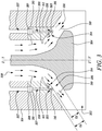
- FIG. 3 an exemplary partial cross-sectional view of the valve seat ring 206 along a section A-A (shown in FIG. 2 ) disposed in the cylinder head 104, and an intake valve 304 associated with the valve seat ring 206 is illustrated.
- the valve seat ring 206 defines a valve seat 303 thereon.
- the intake valve 304 defines a valve axis Y-Y' thereof.
- the intake valve 304 is disposed coaxially with respect to the valve seat ring 206.
- the intake valve 304 is adapted to translate between an open position and a closed position (not shown) along the valve axis Y-Y' with respect to the valve seat ring 206 and the valve seat 303.
- the intake valve 304 is adapted to contact the valve seat ring 206 in the closed position. Also, the intake valve 304 is adapted to provide a valve gap 306 with respect to the valve seat ring 206 in the open position. Further, in the open position of the intake valve 304, the ring bore 208 is adapted to provide fluid communication between the valve gap 306 and a conduit 307 provided in the cylinder head 104. In the closed position of the intake valve 304, the intake valve 304 may contact the valve seat ring 206 and disconnect fluid communication between the ring bore 208 and the valve gap 306.
- intake air flows from an intake manifold 308 in to the respective cylinder 302 via the valve gap 306.
- the intake air in many applications, may include an air-fuel mixture, such as an air-gasoline mixture in case of a gasoline powered engine, an air-gas mixture in case of a natural gas powered engine, and so on, for example.
- the intake air may flow through the valve gap 306 with limited turbulence as shown by arrows 310.
- the valve gap 306 may increase resulting in an increased overall area "OA" of the valve gap 306.
- an edge 312 of the valve seat ring 206 may deflect the intake air flowing through the valve gap 306 in a manner such that a region 314 of flow separation may be formed adjacent to the valve seat ring 206.
- the edge 312 includes a sharply angled configuration. It should be noted that, in other embodiments, the edge 312 may include another angled configuration, such as a beveled configuration, a chamfered configuration, or a curved configuration, such as a filleted configuration, to provide a relatively smooth surface, and so on, based on application requirements.
- the flow separation may be formed due to deflection of the intake air flowing through the valve gap 306 by the intake valve 304. In such a situation, an overall geometry of the intake valve 304 may deflect the intake air away from the intake valve 304. In yet other embodiments, the flow separation may be formed due to a combined effect of the configuration of the edge 312 and the overall geometry of the intake valve 304 and/or the valve gap 306.
- the flow separation of the intake air may further result in increased turbulence and/or backflow of the intake air as shown by arrows 316.
- the region 314, as a result, may reduce an effective area "EA" of the valve gap 306 with respect to the overall area "OA" of the valve gap 306 based on the valve gap 306 exceeding a threshold defined by the valve seat ring 206 and the overall geometry of the intake valve 304.
- the reduced effective area "EA” may result in reduced intake air flow through the valve gap 306 with increase in the valve lift, in turn, reducing an overall performance of the engine 100.
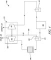
- the intake air delivery system 400 will be hereinafter interchangeably referred to as the "system 400".
- the system 400 includes the intake valve 304 associated with the cylinder 302.
- the intake valve 304 is provided in fluid communication with a compressor section 402 of a turbocharger 404 via an intercooler 406.
- the compressor section 402 of the turbocharger 404 is adapted to receive ambient intake air via an inlet 408 and compress the received intake air to a higher pressure.
- the compressor section 402 of the turbocharger 404 is operably coupled to a turbine section 410 of the turbocharger 404.
- the turbine section 410 is adapted to receive exhaust gas from the cylinder 302 via an exhaust valve 412 associated with the cylinder 302.
- the turbine section 410 is adapted to convert exhaust energy of the exhaust gas to mechanical energy and transfer the mechanical energy to the compressor section 402 of the turbocharger 404.
- the compressed intake air is then cooled in the intercooler 406 downstream of the compressor section 402.
- the intercooler 406 may be any heat exchanger known in the art used for engine applications.
- the intake air is further supplied to the cylinder 302 via the intake valve 304.
- the ring bore 208 associated with the valve seat ring 206 is provided in fluid communication with the inlet 408 of the compressor section 402 of the turbocharger 404 via the conduit 307.
- the conduit 307 and the ring bore 208 may be provided in fluid communication with an inlet of a compressor section of a supercharger (not shown), or an external vacuum pump (not shown), and so on, based on application requirements.
- the conduit 307 and the ring bore 208 may be alternatively provided in fluid communication with ambient air.
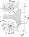
- a suction pressure "SP" of the compressor section 402 is provided to a portion of the valve gap 306 adjacent to the valve seat ring 206. More specifically, referring to FIG. 5 , the suction pressure "SP” is provided in the region 314 adjacent to the valve seat ring 206 via the conduit 307 and the ring bore 208.
- the suction pressure "SP” limits the flow separation and the backflow of the intake air in the region 314. As such, the suction pressure "SP” provides the flow of the intake air through the region 314, in turn, increasing the effective area "EA" of the valve gap 306 up to the overall area "OA" of the valve gap 306.
- the present disclosure relates to a method 600 of working of the intake air delivery system 400.
- a flowchart of the method 600 is illustrated.
- At step 602 at least one bore is provided in the valve seat ring 206 associated with the intake valve 304. More specifically, the conduit 307 is provided in the cylinder head 104 and the ring bore 208 is provided in the valve seat ring 206. The ring bore 208 is axially aligned and in fluid communication with the conduit 307.
- fluid communication is provided between the at least one bore and the valve gap 306 associated with the intake valve 304 in the open position of the intake valve 304. More specifically, fluid communication is provided between the conduit 307, the ring bore 208 and the valve gap 306 in the open position of the intake valve 304.
- the flow of the intake air is provided through the valve gap 306. More specifically, the flow of the intake air is provided through the valve gap 306 in the open position of the intake valve 304, such as during an intake stroke of the engine 100.
- the flow separation and the backflow of the intake air is formed adjacent to the valve seat ring 206. More specifically, the flow separation and the backflow are formed due to deflection of the intake air by the edge 312 of the valve seat ring 206 and/or the overall geometry of the intake valve 304, resulting in the formation of the region 314 of increased turbulence. Also, the flow separation and the resulting backflow and the turbulence is formed based on the valve gap 306 exceeding the threshold.
- the suction pressure "SP” is provided in the valve gap 306 adjacent to the valve seat ring 206 through the at least one bore. More specifically, in the illustrated embodiment, the suction pressure "SP" of the compressor section 402 of the turbocharger 404 is provided adjacent to the valve seat ring 206 through each of the conduit 307 and the ring bore 208. In other embodiments, the suction pressure "SP” may be provided using the supercharger, the external vacuum pump, and so on. At step 612, the flow separation and the backflow of the intake air is limited using the suction pressure "SP".
- the suction pressure "SP" provides to limit formation of the region 314 of the flow separation, the increased turbulence, and the backflow, in turn, increasing the effective area "EA" of the valve gap 306 equal to the overall area "OA” of the valve gap 306. Accordingly, a volume of the intake air may be increased during increasing valve lift of the intake valve 304, thus, improving performance of the engine 100.
- the system 400 provides a simple, efficient, and cost-effective method of limiting the flow separation in the valve gap 306.
- the system 400 employs already available components on the engine 100, such as the turbocharger 404 or the supercharger, in turn, reducing system cost.
- the system 400 may be retrofitted in any engine with little or no modification to the existing system.
Landscapes
- Engineering & Computer Science (AREA)
- Mechanical Engineering (AREA)
- General Engineering & Computer Science (AREA)
- Chemical & Material Sciences (AREA)
- Combustion & Propulsion (AREA)
- Cylinder Crankcases Of Internal Combustion Engines (AREA)
Abstract
Description
- The present disclosure relates to an intake air delivery system. More particularly, the present disclosure relates to the intake air delivery system associated with an internal combustion engine.
- An internal combustion engine, such as a natural gas powered engine, for example, may introduce intake air or a charge air mixture into a cylinder thereof via an intake valve. The intake valve may lift with respect to a valve seat in order to provide a varying valve gap for introduction of the intake air or the charge air mixture into the cylinder. During a relatively higher valve lift, a flow separation may form in the intake air or the charge air mixture flowing through the valve gap.
- In many situations, the flow separation may be formed due to deflection of the intake air or the charge air mixture by an edge of a valve seat or a valve seat ring adjacent to the valve gap. The flow separation may, in turn, result in formation of a region of increased turbulence and backflow in the valve gap. This region may reduce an effective area of the valve gap resulting in reduced amount of the intake air or the charge air mixture flowing through the valve gap, in turn, reducing performance of the engine. Hence, there is a need for an improved system for introduction of the intake air or the charge air mixture into the engine.
-
U.S. Patent Number 5,074,256 describes a lubricating system for a valve seat of an internal combustion engine. The system produces a lubricant oil film on the valve seat of a seat ring. At least a part of the seat ring providing a valve seat surface is made of a porous material readily containing lubricant oil. An outer cylindrical surface of the seat ring is formed with an annular groove along its circumferential direction. A cylinder head to which the seat ring is fastened is formed with an oil passage for feeding lubricant oil to the groove. Feeding of the lubricant oil through the oil passage to the groove causes the valve seat surface to contain lubricant oil. The lubricant oil thus contained produces a lubricant oil film on the valve seat surface, which prevents wear in a valve head and the valve seat surface. - In an aspect of the present disclosure, an intake air delivery system for an engine is provided. The intake air delivery system includes a valve seat ring. The intake air delivery system includes an intake valve provided in association with the valve seat ring. The intake valve is adapted to contact the valve seat ring in a closed position of the intake valve. The intake valve is also adapted to provide a valve gap with respect to the valve seat ring in an open position of the intake valve. The intake air delivery system also includes at least one bore provided in the valve seat ring. The at least one bore is provided in selective fluid communication with the valve gap. The intake air delivery system further includes a conduit provided in fluid communication with the at least one bore and a vacuum pump. Each of the conduit and the at least one bore is adapted to provide a suction pressure of the vacuum pump to a portion of the valve gap adjacent to the valve seat ring.
- In another aspect of the present disclosure, an engine is provided. The engine includes an engine block and a cylinder head mounted on the engine block. The engine also includes a plurality of cylinders provided in the engine block. The engine further includes an intake air delivery system. The intake air delivery system includes at least one valve seat ring provided in association with each of the plurality of cylinders. The intake air delivery system includes an intake valve provided in association with the at least one valve seat ring. The intake valve is adapted to contact the at least one valve seat ring in a closed position of the intake valve. The intake valve is also adapted to provide a valve gap with respect to the at least one valve seat ring in an open position of the intake valve. The intake air delivery system also includes at least one bore provided in the at least one valve seat ring. The at least one bore is provided in selective fluid communication with the valve gap. The intake air delivery system further includes a conduit provided in fluid communication with the at least one bore and a vacuum pump. Each of the conduit and the at least one bore is adapted to provide a suction pressure of the vacuum pump to a portion of the valve gap adjacent to the at least one valve seat ring.
- In yet another aspect of the present disclosure, a method for limiting a flow separation and a backflow of an intake air through an intake valve of an engine is provided. The method includes providing at least one bore in a valve seat ring associated with the intake valve. The method includes providing fluid communication between the at least one bore and a valve gap associated with the intake valve in an open position of the intake valve. The method includes providing a flow of the intake air through the valve gap. The method includes forming the flow separation and the backflow of the intake air adjacent to the valve seat ring. The method also includes providing a suction pressure in the valve gap adjacent to the valve seat ring through the at least one bore. The method further includes limiting the flow separation and the backflow of the intake air using the suction pressure.
- Other features and aspects of this disclosure will be apparent from the following description and the accompanying drawings.
-
-
FIG. 1 is a perspective view of an exemplary engine, according to one embodiment of the present disclosure; -
FIG. 2 is a top view of an exemplary valve seat ring associated with the engine, according to one embodiment of the present disclosure; -
FIG. 3 is a partial cross-sectional view of the valve seat ring along a section A-A (shown inFIG. 2 ), according to one embodiment of the present disclosure; -
FIG. 4 is a schematic representation of an intake air delivery system for the engine, according to one embodiment of the present disclosure; -
FIG. 5 is another partial cross-sectional view of the valve seat ring along the section A-A, according to one embodiment of the present disclosure; and -
FIG. 6 is a flowchart illustrating a method of working of the intake air delivery system ofFIG. 4 , according to one embodiment of the present disclosure. - Wherever possible, the same reference numbers will be used throughout the drawings to refer to the same or the like parts. Referring to
FIG. 1 , anexemplary engine 100 is illustrated. Theengine 100 is an internal combustion engine powered by any fuel known in the art, such as natural gas, gasoline, and/or a combination thereof. In some embodiments, theengine 100 may be associated with a machine (not shown) including, but not limited to, a locomotive, a marine vessel, a land vehicle, and a power generator. Theengine 100 and/or the machine may be employed in any industry including, but not limited to, construction, agriculture, forestry, mining, transportation, waste management, aviation, marine, material handling, and power generation. - The
engine 100 includes anengine block 102. Theengine block 102 may include one or more cylinders 302 (shown inFIG. 3 ) provided therein. Thecylinders 302 may be arranged in any configuration including, but not limited to, an inline, radial, and "V", among others. Each of thecylinders 302 is adapted to receive a piston (not shown) therein. Theengine 100 also includes acylinder head 104 mounted on theengine block 102. Thecylinder head 104 may house one or more components and/or systems (not shown) of theengine 100, such as an intake manifold, an exhaust manifold, a valve train, and sensors, among others. Additionally, theengine 100 may include various other components and/or systems (not shown) including, but not limited to, a crankcase, a fuel system, a cooling system, a lubrication system, a turbocharger, a supercharger, an exhaust gas recirculation system, and peripheries, among others. - Referring to
FIG. 2 , a top view of an exemplaryvalve seat ring 206 is illustrated. Thevalve seat ring 206 is adapted to be disposed in thecylinder head 104. It should be noted that theengine 100 may include one or more valve seat rings 206 associated with each of thecylinders 302, based on application requirements. Thevalve seat ring 206 includes a substantially circular configuration defining an axis X-X' thereof. Thevalve seat ring 206 includes acircumferential groove 207 provided thereon. - The
valve seat ring 206 also includes a plurality of ring bores 208 provided thereon in association with thecircumferential groove 207. Each of the plurality of ring bores 208 is disposed circumferentially on thevalve seat ring 206 and spaced apart with respect to one another. Also, in the illustrated embodiment, each of the plurality of ring bores 208 is disposed substantially parallel with respect to the axis X-X'. In other embodiments, one or more of the plurality of ring bores 208 may be disposed at any angle with respect to the axis X-X'. - Referring to
FIG. 3 , an exemplary partial cross-sectional view of thevalve seat ring 206 along a section A-A (shown inFIG. 2 ) disposed in thecylinder head 104, and anintake valve 304 associated with thevalve seat ring 206 is illustrated. Thevalve seat ring 206 defines avalve seat 303 thereon. Theintake valve 304 defines a valve axis Y-Y' thereof. Theintake valve 304 is disposed coaxially with respect to thevalve seat ring 206. Theintake valve 304 is adapted to translate between an open position and a closed position (not shown) along the valve axis Y-Y' with respect to thevalve seat ring 206 and thevalve seat 303. - Accordingly, the
intake valve 304 is adapted to contact thevalve seat ring 206 in the closed position. Also, theintake valve 304 is adapted to provide avalve gap 306 with respect to thevalve seat ring 206 in the open position. Further, in the open position of theintake valve 304, the ring bore 208 is adapted to provide fluid communication between thevalve gap 306 and aconduit 307 provided in thecylinder head 104. In the closed position of theintake valve 304, theintake valve 304 may contact thevalve seat ring 206 and disconnect fluid communication between the ring bore 208 and thevalve gap 306. - During operation of the
engine 100, in the open position of theintake valve 304, intake air flows from anintake manifold 308 in to therespective cylinder 302 via thevalve gap 306. It should be noted that the intake air, in many applications, may include an air-fuel mixture, such as an air-gasoline mixture in case of a gasoline powered engine, an air-gas mixture in case of a natural gas powered engine, and so on, for example. During a relatively small valve lift, the intake air may flow through thevalve gap 306 with limited turbulence as shown byarrows 310. As the valve lift may increase, thevalve gap 306 may increase resulting in an increased overall area "OA" of thevalve gap 306. - In many situations, an
edge 312 of thevalve seat ring 206 may deflect the intake air flowing through thevalve gap 306 in a manner such that aregion 314 of flow separation may be formed adjacent to thevalve seat ring 206. In the illustrated embodiment, theedge 312 includes a sharply angled configuration. It should be noted that, in other embodiments, theedge 312 may include another angled configuration, such as a beveled configuration, a chamfered configuration, or a curved configuration, such as a filleted configuration, to provide a relatively smooth surface, and so on, based on application requirements. - Also, it should be noted, that in some embodiments, the flow separation may be formed due to deflection of the intake air flowing through the
valve gap 306 by theintake valve 304. In such a situation, an overall geometry of theintake valve 304 may deflect the intake air away from theintake valve 304. In yet other embodiments, the flow separation may be formed due to a combined effect of the configuration of theedge 312 and the overall geometry of theintake valve 304 and/or thevalve gap 306. - The flow separation of the intake air may further result in increased turbulence and/or backflow of the intake air as shown by
arrows 316. Theregion 314, as a result, may reduce an effective area "EA" of thevalve gap 306 with respect to the overall area "OA" of thevalve gap 306 based on thevalve gap 306 exceeding a threshold defined by thevalve seat ring 206 and the overall geometry of theintake valve 304. The reduced effective area "EA" may result in reduced intake air flow through thevalve gap 306 with increase in the valve lift, in turn, reducing an overall performance of theengine 100. - Referring to
FIG. 4 , a schematic representation of an intakeair delivery system 400 for theengine 100 is illustrated. The intakeair delivery system 400 will be hereinafter interchangeably referred to as the "system 400". Thesystem 400 includes theintake valve 304 associated with thecylinder 302. Theintake valve 304 is provided in fluid communication with acompressor section 402 of aturbocharger 404 via anintercooler 406. Thecompressor section 402 of theturbocharger 404 is adapted to receive ambient intake air via aninlet 408 and compress the received intake air to a higher pressure. - The
compressor section 402 of theturbocharger 404 is operably coupled to aturbine section 410 of theturbocharger 404. Theturbine section 410 is adapted to receive exhaust gas from thecylinder 302 via anexhaust valve 412 associated with thecylinder 302. Theturbine section 410 is adapted to convert exhaust energy of the exhaust gas to mechanical energy and transfer the mechanical energy to thecompressor section 402 of theturbocharger 404. The compressed intake air is then cooled in theintercooler 406 downstream of thecompressor section 402. Theintercooler 406 may be any heat exchanger known in the art used for engine applications. The intake air is further supplied to thecylinder 302 via theintake valve 304. - Additionally, the ring bore 208 associated with the
valve seat ring 206 is provided in fluid communication with theinlet 408 of thecompressor section 402 of theturbocharger 404 via theconduit 307. It should be noted that, in other embodiments, theconduit 307 and the ring bore 208 may be provided in fluid communication with an inlet of a compressor section of a supercharger (not shown), or an external vacuum pump (not shown), and so on, based on application requirements. Also, it should be noted that, in some embodiments, such as in a direct injection engine, theconduit 307 and the ring bore 208 may be alternatively provided in fluid communication with ambient air. - Based on the
valve gap 306 exceeding the threshold, a suction pressure "SP" of thecompressor section 402 is provided to a portion of thevalve gap 306 adjacent to thevalve seat ring 206. More specifically, referring toFIG. 5 , the suction pressure "SP" is provided in theregion 314 adjacent to thevalve seat ring 206 via theconduit 307 and the ring bore 208. The suction pressure "SP" limits the flow separation and the backflow of the intake air in theregion 314. As such, the suction pressure "SP" provides the flow of the intake air through theregion 314, in turn, increasing the effective area "EA" of thevalve gap 306 up to the overall area "OA" of thevalve gap 306. - The present disclosure relates to a
method 600 of working of the intakeair delivery system 400. Referring toFIG. 6 , a flowchart of themethod 600 is illustrated. Atstep 602, at least one bore is provided in thevalve seat ring 206 associated with theintake valve 304. More specifically, theconduit 307 is provided in thecylinder head 104 and the ring bore 208 is provided in thevalve seat ring 206. The ring bore 208 is axially aligned and in fluid communication with theconduit 307. - At
step 604, fluid communication is provided between the at least one bore and thevalve gap 306 associated with theintake valve 304 in the open position of theintake valve 304. More specifically, fluid communication is provided between theconduit 307, the ring bore 208 and thevalve gap 306 in the open position of theintake valve 304. Atstep 606, the flow of the intake air is provided through thevalve gap 306. More specifically, the flow of the intake air is provided through thevalve gap 306 in the open position of theintake valve 304, such as during an intake stroke of theengine 100. - At
step 608, the flow separation and the backflow of the intake air is formed adjacent to thevalve seat ring 206. More specifically, the flow separation and the backflow are formed due to deflection of the intake air by theedge 312 of thevalve seat ring 206 and/or the overall geometry of theintake valve 304, resulting in the formation of theregion 314 of increased turbulence. Also, the flow separation and the resulting backflow and the turbulence is formed based on thevalve gap 306 exceeding the threshold. - At
step 610, the suction pressure "SP" is provided in thevalve gap 306 adjacent to thevalve seat ring 206 through the at least one bore. More specifically, in the illustrated embodiment, the suction pressure "SP" of thecompressor section 402 of theturbocharger 404 is provided adjacent to thevalve seat ring 206 through each of theconduit 307 and the ring bore 208. In other embodiments, the suction pressure "SP" may be provided using the supercharger, the external vacuum pump, and so on. Atstep 612, the flow separation and the backflow of the intake air is limited using the suction pressure "SP". - As such, the suction pressure "SP" provides to limit formation of the
region 314 of the flow separation, the increased turbulence, and the backflow, in turn, increasing the effective area "EA" of thevalve gap 306 equal to the overall area "OA" of thevalve gap 306. Accordingly, a volume of the intake air may be increased during increasing valve lift of theintake valve 304, thus, improving performance of theengine 100. Thesystem 400 provides a simple, efficient, and cost-effective method of limiting the flow separation in thevalve gap 306. Thesystem 400 employs already available components on theengine 100, such as theturbocharger 404 or the supercharger, in turn, reducing system cost. Thesystem 400 may be retrofitted in any engine with little or no modification to the existing system. - While aspects of the present disclosure have been particularly shown and described with reference to the embodiments above, it will be understood by those skilled in the art that various additional embodiments may be contemplated by the modification of the disclosed machines, systems and methods without departing from the spirit and scope of the disclosure. Such embodiments should be understood to fall within the scope of the present disclosure as determined based upon the claims and any equivalents thereof.
Claims (15)
- An intake air delivery system (400) for an engine (100), the intake air delivery system (400) comprising:a valve seat ring (206);an intake valve (304) provided in association with the valve seat ring (206), the intake valve (304) adapted to contact the valve seat ring (206) in a closed position of the intake valve (304), the intake valve (304) adapted to provide a valve gap (306) with respect to the valve seat ring (206) in an open position of the intake valve (304);at least one bore (208) provided in the valve seat ring (206), the at least one bore (208) provided in selective fluid communication with the valve gap (306); anda conduit (307) provided in fluid communication with the at least one bore (208) and a vacuum pump, wherein each of the conduit (307) and the at least one bore (208) is adapted to provide a suction pressure of the vacuum pump to a portion of the valve gap (306) adjacent to the valve seat ring (206).
- The intake air delivery system (400) of claim 1, wherein the intake air is an air-fuel mixture.
- The intake air delivery system (400) of claim 1, wherein the conduit (307) is provided in a cylinder head (104) associated with the engine (100).
- The intake air delivery system (400) of claim 1, wherein the at least one bore (208) is provided in fluid communication with the valve gap (306) in the open position of the intake valve (304).
- The intake air delivery system (400) of claim 1, wherein the vacuum pump is a compressor section (402) associated with any one of a supercharger and a turbocharger (404) associated with the engine (100).
- An engine (100) comprising:an engine block (102);a cylinder head (104) mounted on the engine block (102);a plurality of cylinders provided in the engine block (102); andan intake air delivery system (400) comprising:at least one valve seat ring (206) provided in association with each of the plurality of cylinders;an intake valve (304) provided in association with the at least one valve seat ring (206), the intake valve (304) adapted to contact the at least one valve seat ring (206) in a closed position of the intake valve (304), the intake valve (304) adapted to provide a valve gap (306) with respect to the at least one valve seat ring (206) in an open position of the intake valve (304);at least one bore (208) provided in the at least one valve seat ring (206), the at least one bore (208) provided in selective fluid communication with the valve gap (306); anda conduit (307) provided in fluid communication with the at least one bore (208) and a vacuum pump, wherein each of the conduit (307) and the at least one bore (208) is adapted to provide a suction pressure of the vacuum pump to a portion of the valve gap (306) adjacent to the at least one valve seat ring (206).
- The engine (100) of claim 6, wherein the intake air is an air-fuel mixture.
- The engine (100) of claim 6, wherein the conduit (307) is provided in the cylinder head (104).
- The engine (100) of claim 6, wherein the at least one bore (208) is provided in fluid communication with the valve gap (306) in the open position of the intake valve (304).
- The engine (100) of claim 6, wherein the at least one bore (208) includes a plurality of bores (208) disposed adjacent and spaced apart with respect to one another.
- The engine (100) of claim 6, wherein the vacuum pump is a compressor section (402) associated with any one of a supercharger and a turbocharger (404) associated with the engine (100).
- The engine (100) of claim 6 is at least one of a gasoline powered engine (100) and a natural gas powered engine (100).
- A method (600) for limiting a flow separation and a backflow of an intake air through an intake valve (304) of an engine (100), the method (600) comprising:providing at least one bore (208) in a valve seat ring (206) associated with the intake valve (304);providing fluid communication between the at least one bore (208) and a valve gap (306) associated with the intake valve (304) in an open position of the intake valve (304);providing a flow of the intake air through the valve gap (306);forming the flow separation and the backflow of the intake air adjacent to the valve seat ring (206);providing a suction pressure in the valve gap (306) adjacent to the valve seat ring (206) through the at least one bore (208); andlimiting the flow separation and the backflow of the intake air using the suction pressure.
- The method (600) of claim 13, wherein the flow separation is formed based on the valve gap (306) exceeding a threshold defined by the valve seat ring (206) and a geometry of the intake valve (304).
- The method (600) of claim 13, wherein the suction pressure is provided using a compressor section (402) associated with any one of a supercharger and a turbocharger (404) associated with the engine (100).
Applications Claiming Priority (1)
| Application Number | Priority Date | Filing Date | Title |
|---|---|---|---|
| GB1804405.7A GB2572157B (en) | 2018-03-20 | 2018-03-20 | Intake air delivery system |
Publications (2)
| Publication Number | Publication Date |
|---|---|
| EP3575564A1 true EP3575564A1 (en) | 2019-12-04 |
| EP3575564B1 EP3575564B1 (en) | 2021-12-15 |
Family
ID=62017725
Family Applications (1)
| Application Number | Title | Priority Date | Filing Date |
|---|---|---|---|
| EP19163575.4A Active EP3575564B1 (en) | 2018-03-20 | 2019-03-18 | Intake air delivery system |
Country Status (2)
| Country | Link |
|---|---|
| EP (1) | EP3575564B1 (en) |
| GB (1) | GB2572157B (en) |
Citations (3)
| Publication number | Priority date | Publication date | Assignee | Title |
|---|---|---|---|---|
| US4422430A (en) * | 1980-11-28 | 1983-12-27 | Osrodek Badawczo-Rozwojowy Samochodow Malolitrazowych Bosmal | Method and a system for the creation of turbulence and gasification of the air-fuel mixture |
| DE4209684A1 (en) * | 1992-03-25 | 1993-09-30 | Porsche Ag | Device for influencing the flow in gas exchange channels of an internal combustion engine |
| DE19920516A1 (en) * | 1999-05-05 | 2000-11-16 | Daimler Chrysler Ag | Reducing emissions during combustion engine cold starts involves producing vacuum in each inlet channel before inlet valve using vacuum pump to suck up condensed fuel droplets |
Family Cites Families (2)
| Publication number | Priority date | Publication date | Assignee | Title |
|---|---|---|---|---|
| JPS5026903A (en) * | 1973-07-12 | 1975-03-20 | ||
| JPS5821090B2 (en) * | 1977-07-04 | 1983-04-27 | 三菱自動車工業株式会社 | air injection gasoline engine |
-
2018
- 2018-03-20 GB GB1804405.7A patent/GB2572157B/en active Active
-
2019
- 2019-03-18 EP EP19163575.4A patent/EP3575564B1/en active Active
Patent Citations (3)
| Publication number | Priority date | Publication date | Assignee | Title |
|---|---|---|---|---|
| US4422430A (en) * | 1980-11-28 | 1983-12-27 | Osrodek Badawczo-Rozwojowy Samochodow Malolitrazowych Bosmal | Method and a system for the creation of turbulence and gasification of the air-fuel mixture |
| DE4209684A1 (en) * | 1992-03-25 | 1993-09-30 | Porsche Ag | Device for influencing the flow in gas exchange channels of an internal combustion engine |
| DE19920516A1 (en) * | 1999-05-05 | 2000-11-16 | Daimler Chrysler Ag | Reducing emissions during combustion engine cold starts involves producing vacuum in each inlet channel before inlet valve using vacuum pump to suck up condensed fuel droplets |
Also Published As
| Publication number | Publication date |
|---|---|
| EP3575564B1 (en) | 2021-12-15 |
| GB2572157A (en) | 2019-09-25 |
| GB2572157B (en) | 2020-12-09 |
| GB201804405D0 (en) | 2018-05-02 |
Similar Documents
| Publication | Publication Date | Title |
|---|---|---|
| CN106065798B (en) | Crankcase ventilation pressure management system for turbocharged engine | |
| CN101684764B (en) | Resonator and crankcase ventilation system for internal combustion engine | |
| US20090020958A1 (en) | Methods and apparatus for operating an internal combustion engine | |
| EP2182185B1 (en) | Crankcase ventilation system for engine | |
| CN107816397B (en) | Blowby gas treatment device for internal combustion engine with supercharger | |
| US10145277B2 (en) | Crankcase ventilation for turbocharged engine | |
| US20130228150A1 (en) | Rotary, Internal Combustion Engine | |
| US20100313860A1 (en) | Apparatus for removal of oil from positive crankcase ventilation system | |
| US9121330B2 (en) | Porting system for a turbo-charged loop scavenged two-stroked engine | |
| CN105484826A (en) | Crankcase ventilation system | |
| US10746099B1 (en) | Multi-step bore turbocharger | |
| EP3575564B1 (en) | Intake air delivery system | |
| US10113455B2 (en) | Regulator assembly | |
| KR102882667B1 (en) | A piston ring for use in a ring pack in a piston of a large two-stroke turbo-charged uniflow-scavenged internal combustion engine with crossheads | |
| US9964010B2 (en) | Turbocharger actuation shaft exhaust leakage containment method | |
| US20190085743A1 (en) | Throttled pcv system for an engine | |
| US9194327B2 (en) | Cylinder liner with slots | |
| WO2007115170A2 (en) | Methods and apparatus for operating an internal combustion engine | |
| CN120061995A (en) | Valve cover assembly for an internal combustion engine | |
| JP6875871B2 (en) | Blow-by gas device | |
| AU2021329294B2 (en) | Head assembly with rotary valves for an internal combustion engine | |
| KR20140139532A (en) | Charge air guide element for internal combustion engine | |
| EP3714176B1 (en) | Turbocharger for an internal combustion engine | |
| CN107120208A (en) | Cylinder cover sealing gasket for explosive motor | |
| CN217440129U (en) | Supercharged engine crankcase ventilation system |
Legal Events
| Date | Code | Title | Description |
|---|---|---|---|
| PUAI | Public reference made under article 153(3) epc to a published international application that has entered the european phase |
Free format text: ORIGINAL CODE: 0009012 |
|
| STAA | Information on the status of an ep patent application or granted ep patent |
Free format text: STATUS: THE APPLICATION HAS BEEN PUBLISHED |
|
| AK | Designated contracting states |
Kind code of ref document: A1 Designated state(s): AL AT BE BG CH CY CZ DE DK EE ES FI FR GB GR HR HU IE IS IT LI LT LU LV MC MK MT NL NO PL PT RO RS SE SI SK SM TR |
|
| AX | Request for extension of the european patent |
Extension state: BA ME |
|
| STAA | Information on the status of an ep patent application or granted ep patent |
Free format text: STATUS: REQUEST FOR EXAMINATION WAS MADE |
|
| 17P | Request for examination filed |
Effective date: 20200529 |
|
| RBV | Designated contracting states (corrected) |
Designated state(s): AL AT BE BG CH CY CZ DE DK EE ES FI FR GB GR HR HU IE IS IT LI LT LU LV MC MK MT NL NO PL PT RO RS SE SI SK SM TR |
|
| STAA | Information on the status of an ep patent application or granted ep patent |
Free format text: STATUS: EXAMINATION IS IN PROGRESS |
|
| 17Q | First examination report despatched |
Effective date: 20200804 |
|
| 17Q | First examination report despatched |
Effective date: 20201014 |
|
| RIN1 | Information on inventor provided before grant (corrected) |
Inventor name: WILSTERMANN, THOMAS |
|
| GRAP | Despatch of communication of intention to grant a patent |
Free format text: ORIGINAL CODE: EPIDOSNIGR1 |
|
| STAA | Information on the status of an ep patent application or granted ep patent |
Free format text: STATUS: GRANT OF PATENT IS INTENDED |
|
| INTG | Intention to grant announced |
Effective date: 20210708 |
|
| GRAS | Grant fee paid |
Free format text: ORIGINAL CODE: EPIDOSNIGR3 |
|
| GRAA | (expected) grant |
Free format text: ORIGINAL CODE: 0009210 |
|
| STAA | Information on the status of an ep patent application or granted ep patent |
Free format text: STATUS: THE PATENT HAS BEEN GRANTED |
|
| AK | Designated contracting states |
Kind code of ref document: B1 Designated state(s): AL AT BE BG CH CY CZ DE DK EE ES FI FR GB GR HR HU IE IS IT LI LT LU LV MC MK MT NL NO PL PT RO RS SE SI SK SM TR |
|
| REG | Reference to a national code |
Ref country code: GB Ref legal event code: FG4D Ref country code: CH Ref legal event code: EP |
|
| REG | Reference to a national code |
Ref country code: DE Ref legal event code: R096 Ref document number: 602019009994 Country of ref document: DE |
|
| REG | Reference to a national code |
Ref country code: IE Ref legal event code: FG4D |
|
| REG | Reference to a national code |
Ref country code: AT Ref legal event code: REF Ref document number: 1455649 Country of ref document: AT Kind code of ref document: T Effective date: 20220115 |
|
| REG | Reference to a national code |
Ref country code: LT Ref legal event code: MG9D |
|
| REG | Reference to a national code |
Ref country code: NL Ref legal event code: MP Effective date: 20211215 |
|
| PG25 | Lapsed in a contracting state [announced via postgrant information from national office to epo] |
Ref country code: RS Free format text: LAPSE BECAUSE OF FAILURE TO SUBMIT A TRANSLATION OF THE DESCRIPTION OR TO PAY THE FEE WITHIN THE PRESCRIBED TIME-LIMIT Effective date: 20211215 Ref country code: LT Free format text: LAPSE BECAUSE OF FAILURE TO SUBMIT A TRANSLATION OF THE DESCRIPTION OR TO PAY THE FEE WITHIN THE PRESCRIBED TIME-LIMIT Effective date: 20211215 Ref country code: FI Free format text: LAPSE BECAUSE OF FAILURE TO SUBMIT A TRANSLATION OF THE DESCRIPTION OR TO PAY THE FEE WITHIN THE PRESCRIBED TIME-LIMIT Effective date: 20211215 Ref country code: BG Free format text: LAPSE BECAUSE OF FAILURE TO SUBMIT A TRANSLATION OF THE DESCRIPTION OR TO PAY THE FEE WITHIN THE PRESCRIBED TIME-LIMIT Effective date: 20220315 |
|
| REG | Reference to a national code |
Ref country code: AT Ref legal event code: MK05 Ref document number: 1455649 Country of ref document: AT Kind code of ref document: T Effective date: 20211215 |
|
| PG25 | Lapsed in a contracting state [announced via postgrant information from national office to epo] |
Ref country code: SE Free format text: LAPSE BECAUSE OF FAILURE TO SUBMIT A TRANSLATION OF THE DESCRIPTION OR TO PAY THE FEE WITHIN THE PRESCRIBED TIME-LIMIT Effective date: 20211215 Ref country code: NO Free format text: LAPSE BECAUSE OF FAILURE TO SUBMIT A TRANSLATION OF THE DESCRIPTION OR TO PAY THE FEE WITHIN THE PRESCRIBED TIME-LIMIT Effective date: 20220315 Ref country code: LV Free format text: LAPSE BECAUSE OF FAILURE TO SUBMIT A TRANSLATION OF THE DESCRIPTION OR TO PAY THE FEE WITHIN THE PRESCRIBED TIME-LIMIT Effective date: 20211215 Ref country code: HR Free format text: LAPSE BECAUSE OF FAILURE TO SUBMIT A TRANSLATION OF THE DESCRIPTION OR TO PAY THE FEE WITHIN THE PRESCRIBED TIME-LIMIT Effective date: 20211215 Ref country code: GR Free format text: LAPSE BECAUSE OF FAILURE TO SUBMIT A TRANSLATION OF THE DESCRIPTION OR TO PAY THE FEE WITHIN THE PRESCRIBED TIME-LIMIT Effective date: 20220316 |
|
| PG25 | Lapsed in a contracting state [announced via postgrant information from national office to epo] |
Ref country code: NL Free format text: LAPSE BECAUSE OF FAILURE TO SUBMIT A TRANSLATION OF THE DESCRIPTION OR TO PAY THE FEE WITHIN THE PRESCRIBED TIME-LIMIT Effective date: 20211215 |
|
| PG25 | Lapsed in a contracting state [announced via postgrant information from national office to epo] |
Ref country code: SM Free format text: LAPSE BECAUSE OF FAILURE TO SUBMIT A TRANSLATION OF THE DESCRIPTION OR TO PAY THE FEE WITHIN THE PRESCRIBED TIME-LIMIT Effective date: 20211215 Ref country code: SK Free format text: LAPSE BECAUSE OF FAILURE TO SUBMIT A TRANSLATION OF THE DESCRIPTION OR TO PAY THE FEE WITHIN THE PRESCRIBED TIME-LIMIT Effective date: 20211215 Ref country code: RO Free format text: LAPSE BECAUSE OF FAILURE TO SUBMIT A TRANSLATION OF THE DESCRIPTION OR TO PAY THE FEE WITHIN THE PRESCRIBED TIME-LIMIT Effective date: 20211215 Ref country code: PT Free format text: LAPSE BECAUSE OF FAILURE TO SUBMIT A TRANSLATION OF THE DESCRIPTION OR TO PAY THE FEE WITHIN THE PRESCRIBED TIME-LIMIT Effective date: 20220418 Ref country code: ES Free format text: LAPSE BECAUSE OF FAILURE TO SUBMIT A TRANSLATION OF THE DESCRIPTION OR TO PAY THE FEE WITHIN THE PRESCRIBED TIME-LIMIT Effective date: 20211215 Ref country code: EE Free format text: LAPSE BECAUSE OF FAILURE TO SUBMIT A TRANSLATION OF THE DESCRIPTION OR TO PAY THE FEE WITHIN THE PRESCRIBED TIME-LIMIT Effective date: 20211215 Ref country code: CZ Free format text: LAPSE BECAUSE OF FAILURE TO SUBMIT A TRANSLATION OF THE DESCRIPTION OR TO PAY THE FEE WITHIN THE PRESCRIBED TIME-LIMIT Effective date: 20211215 |
|
| PG25 | Lapsed in a contracting state [announced via postgrant information from national office to epo] |
Ref country code: PL Free format text: LAPSE BECAUSE OF FAILURE TO SUBMIT A TRANSLATION OF THE DESCRIPTION OR TO PAY THE FEE WITHIN THE PRESCRIBED TIME-LIMIT Effective date: 20211215 Ref country code: AT Free format text: LAPSE BECAUSE OF FAILURE TO SUBMIT A TRANSLATION OF THE DESCRIPTION OR TO PAY THE FEE WITHIN THE PRESCRIBED TIME-LIMIT Effective date: 20211215 |
|
| REG | Reference to a national code |
Ref country code: DE Ref legal event code: R097 Ref document number: 602019009994 Country of ref document: DE |
|
| PG25 | Lapsed in a contracting state [announced via postgrant information from national office to epo] |
Ref country code: IS Free format text: LAPSE BECAUSE OF FAILURE TO SUBMIT A TRANSLATION OF THE DESCRIPTION OR TO PAY THE FEE WITHIN THE PRESCRIBED TIME-LIMIT Effective date: 20220415 |
|
| PLBE | No opposition filed within time limit |
Free format text: ORIGINAL CODE: 0009261 |
|
| STAA | Information on the status of an ep patent application or granted ep patent |
Free format text: STATUS: NO OPPOSITION FILED WITHIN TIME LIMIT |
|
| PG25 | Lapsed in a contracting state [announced via postgrant information from national office to epo] |
Ref country code: MC Free format text: LAPSE BECAUSE OF FAILURE TO SUBMIT A TRANSLATION OF THE DESCRIPTION OR TO PAY THE FEE WITHIN THE PRESCRIBED TIME-LIMIT Effective date: 20211215 Ref country code: DK Free format text: LAPSE BECAUSE OF FAILURE TO SUBMIT A TRANSLATION OF THE DESCRIPTION OR TO PAY THE FEE WITHIN THE PRESCRIBED TIME-LIMIT Effective date: 20211215 Ref country code: AL Free format text: LAPSE BECAUSE OF FAILURE TO SUBMIT A TRANSLATION OF THE DESCRIPTION OR TO PAY THE FEE WITHIN THE PRESCRIBED TIME-LIMIT Effective date: 20211215 |
|
| REG | Reference to a national code |
Ref country code: CH Ref legal event code: PL |
|
| 26N | No opposition filed |
Effective date: 20220916 |
|
| PG25 | Lapsed in a contracting state [announced via postgrant information from national office to epo] |
Ref country code: SI Free format text: LAPSE BECAUSE OF FAILURE TO SUBMIT A TRANSLATION OF THE DESCRIPTION OR TO PAY THE FEE WITHIN THE PRESCRIBED TIME-LIMIT Effective date: 20211215 |
|
| REG | Reference to a national code |
Ref country code: BE Ref legal event code: MM Effective date: 20220331 |
|
| PG25 | Lapsed in a contracting state [announced via postgrant information from national office to epo] |
Ref country code: LU Free format text: LAPSE BECAUSE OF NON-PAYMENT OF DUE FEES Effective date: 20220318 Ref country code: LI Free format text: LAPSE BECAUSE OF NON-PAYMENT OF DUE FEES Effective date: 20220331 Ref country code: IE Free format text: LAPSE BECAUSE OF NON-PAYMENT OF DUE FEES Effective date: 20220318 Ref country code: FR Free format text: LAPSE BECAUSE OF NON-PAYMENT OF DUE FEES Effective date: 20220331 Ref country code: CH Free format text: LAPSE BECAUSE OF NON-PAYMENT OF DUE FEES Effective date: 20220331 |
|
| PG25 | Lapsed in a contracting state [announced via postgrant information from national office to epo] |
Ref country code: BE Free format text: LAPSE BECAUSE OF NON-PAYMENT OF DUE FEES Effective date: 20220331 |
|
| PG25 | Lapsed in a contracting state [announced via postgrant information from national office to epo] |
Ref country code: IT Free format text: LAPSE BECAUSE OF FAILURE TO SUBMIT A TRANSLATION OF THE DESCRIPTION OR TO PAY THE FEE WITHIN THE PRESCRIBED TIME-LIMIT Effective date: 20211215 |
|
| P01 | Opt-out of the competence of the unified patent court (upc) registered |
Effective date: 20230526 |
|
| GBPC | Gb: european patent ceased through non-payment of renewal fee |
Effective date: 20230318 |
|
| PG25 | Lapsed in a contracting state [announced via postgrant information from national office to epo] |
Ref country code: GB Free format text: LAPSE BECAUSE OF NON-PAYMENT OF DUE FEES Effective date: 20230318 |
|
| PG25 | Lapsed in a contracting state [announced via postgrant information from national office to epo] |
Ref country code: GB Free format text: LAPSE BECAUSE OF NON-PAYMENT OF DUE FEES Effective date: 20230318 |
|
| PG25 | Lapsed in a contracting state [announced via postgrant information from national office to epo] |
Ref country code: MK Free format text: LAPSE BECAUSE OF FAILURE TO SUBMIT A TRANSLATION OF THE DESCRIPTION OR TO PAY THE FEE WITHIN THE PRESCRIBED TIME-LIMIT Effective date: 20211215 Ref country code: CY Free format text: LAPSE BECAUSE OF FAILURE TO SUBMIT A TRANSLATION OF THE DESCRIPTION OR TO PAY THE FEE WITHIN THE PRESCRIBED TIME-LIMIT Effective date: 20211215 |
|
| PG25 | Lapsed in a contracting state [announced via postgrant information from national office to epo] |
Ref country code: HU Free format text: LAPSE BECAUSE OF FAILURE TO SUBMIT A TRANSLATION OF THE DESCRIPTION OR TO PAY THE FEE WITHIN THE PRESCRIBED TIME-LIMIT; INVALID AB INITIO Effective date: 20190318 |
|
| PG25 | Lapsed in a contracting state [announced via postgrant information from national office to epo] |
Ref country code: MT Free format text: LAPSE BECAUSE OF FAILURE TO SUBMIT A TRANSLATION OF THE DESCRIPTION OR TO PAY THE FEE WITHIN THE PRESCRIBED TIME-LIMIT Effective date: 20211215 |
|
| PG25 | Lapsed in a contracting state [announced via postgrant information from national office to epo] |
Ref country code: TR Free format text: LAPSE BECAUSE OF FAILURE TO SUBMIT A TRANSLATION OF THE DESCRIPTION OR TO PAY THE FEE WITHIN THE PRESCRIBED TIME-LIMIT Effective date: 20211215 |
|
| PGFP | Annual fee paid to national office [announced via postgrant information from national office to epo] |
Ref country code: DE Payment date: 20260219 Year of fee payment: 8 |