EP3575545A1 - Ensemble destiné à être utilisé dans un puits de forage et procédé associé - Google Patents
Ensemble destiné à être utilisé dans un puits de forage et procédé associé Download PDFInfo
- Publication number
- EP3575545A1 EP3575545A1 EP18175338.5A EP18175338A EP3575545A1 EP 3575545 A1 EP3575545 A1 EP 3575545A1 EP 18175338 A EP18175338 A EP 18175338A EP 3575545 A1 EP3575545 A1 EP 3575545A1
- Authority
- EP
- European Patent Office
- Prior art keywords
- elements
- assembly
- interior
- passageway
- substance
- Prior art date
- Legal status (The legal status is an assumption and is not a legal conclusion. Google has not performed a legal analysis and makes no representation as to the accuracy of the status listed.)
- Withdrawn
Links
- 238000000034 method Methods 0.000 title claims abstract description 29
- 239000000463 material Substances 0.000 claims abstract description 96
- 239000000126 substance Substances 0.000 claims abstract description 86
- 230000004913 activation Effects 0.000 claims abstract description 64
- 238000004891 communication Methods 0.000 claims abstract description 12
- 230000004044 response Effects 0.000 claims abstract description 12
- 239000012530 fluid Substances 0.000 claims description 166
- 230000004888 barrier function Effects 0.000 claims description 33
- 230000000903 blocking effect Effects 0.000 claims description 21
- 238000004519 manufacturing process Methods 0.000 claims description 16
- 230000006378 damage Effects 0.000 claims description 9
- 230000003213 activating effect Effects 0.000 claims description 8
- 230000008569 process Effects 0.000 claims description 7
- 230000008859 change Effects 0.000 claims description 5
- 238000006243 chemical reaction Methods 0.000 claims description 3
- FAPWRFPIFSIZLT-UHFFFAOYSA-M Sodium chloride Chemical compound [Na+].[Cl-] FAPWRFPIFSIZLT-UHFFFAOYSA-M 0.000 description 16
- 239000000203 mixture Substances 0.000 description 15
- 239000003755 preservative agent Substances 0.000 description 11
- 230000002335 preservative effect Effects 0.000 description 11
- 230000007797 corrosion Effects 0.000 description 10
- 238000005260 corrosion Methods 0.000 description 10
- 239000011780 sodium chloride Substances 0.000 description 10
- XLYOFNOQVPJJNP-UHFFFAOYSA-N water Substances O XLYOFNOQVPJJNP-UHFFFAOYSA-N 0.000 description 9
- 239000008151 electrolyte solution Substances 0.000 description 8
- 239000002253 acid Substances 0.000 description 7
- WCUXLLCKKVVCTQ-UHFFFAOYSA-M Potassium chloride Chemical compound [Cl-].[K+] WCUXLLCKKVVCTQ-UHFFFAOYSA-M 0.000 description 6
- 239000004411 aluminium Substances 0.000 description 6
- 229910052782 aluminium Inorganic materials 0.000 description 6
- XAGFODPZIPBFFR-UHFFFAOYSA-N aluminium Chemical compound [Al] XAGFODPZIPBFFR-UHFFFAOYSA-N 0.000 description 6
- 239000011521 glass Substances 0.000 description 6
- 239000007769 metal material Substances 0.000 description 5
- 239000000376 reactant Substances 0.000 description 5
- 150000003839 salts Chemical class 0.000 description 5
- 229910000838 Al alloy Inorganic materials 0.000 description 4
- GYHNNYVSQQEPJS-UHFFFAOYSA-N Gallium Chemical compound [Ga] GYHNNYVSQQEPJS-UHFFFAOYSA-N 0.000 description 4
- 229910000861 Mg alloy Inorganic materials 0.000 description 4
- 230000008901 benefit Effects 0.000 description 4
- 239000012267 brine Substances 0.000 description 4
- 239000000470 constituent Substances 0.000 description 4
- 239000012153 distilled water Substances 0.000 description 4
- 229910052751 metal Inorganic materials 0.000 description 4
- 239000002184 metal Substances 0.000 description 4
- 229910001092 metal group alloy Inorganic materials 0.000 description 4
- 239000002245 particle Substances 0.000 description 4
- HPALAKNZSZLMCH-UHFFFAOYSA-M sodium;chloride;hydrate Chemical compound O.[Na+].[Cl-] HPALAKNZSZLMCH-UHFFFAOYSA-M 0.000 description 4
- 239000000243 solution Substances 0.000 description 4
- 238000012360 testing method Methods 0.000 description 4
- 239000011248 coating agent Substances 0.000 description 3
- 238000000576 coating method Methods 0.000 description 3
- 230000000593 degrading effect Effects 0.000 description 3
- 229910052733 gallium Inorganic materials 0.000 description 3
- 239000004033 plastic Substances 0.000 description 3
- 229920003023 plastic Polymers 0.000 description 3
- 235000011164 potassium chloride Nutrition 0.000 description 3
- 239000001103 potassium chloride Substances 0.000 description 3
- 239000004215 Carbon black (E152) Substances 0.000 description 2
- 229910000807 Ga alloy Inorganic materials 0.000 description 2
- FYYHWMGAXLPEAU-UHFFFAOYSA-N Magnesium Chemical compound [Mg] FYYHWMGAXLPEAU-UHFFFAOYSA-N 0.000 description 2
- 229920000954 Polyglycolide Polymers 0.000 description 2
- 239000003518 caustics Substances 0.000 description 2
- 230000006866 deterioration Effects 0.000 description 2
- 238000004090 dissolution Methods 0.000 description 2
- 229930195733 hydrocarbon Natural products 0.000 description 2
- 150000002430 hydrocarbons Chemical class 0.000 description 2
- 238000011065 in-situ storage Methods 0.000 description 2
- 150000002500 ions Chemical class 0.000 description 2
- 239000011777 magnesium Substances 0.000 description 2
- 229910052749 magnesium Inorganic materials 0.000 description 2
- 239000012528 membrane Substances 0.000 description 2
- 239000004633 polyglycolic acid Substances 0.000 description 2
- DGAQECJNVWCQMB-PUAWFVPOSA-M Ilexoside XXIX Chemical compound C[C@@H]1CC[C@@]2(CC[C@@]3(C(=CC[C@H]4[C@]3(CC[C@@H]5[C@@]4(CC[C@@H](C5(C)C)OS(=O)(=O)[O-])C)C)[C@@H]2[C@]1(C)O)C)C(=O)O[C@H]6[C@@H]([C@H]([C@@H]([C@H](O6)CO)O)O)O.[Na+] DGAQECJNVWCQMB-PUAWFVPOSA-M 0.000 description 1
- ZLMJMSJWJFRBEC-UHFFFAOYSA-N Potassium Chemical compound [K] ZLMJMSJWJFRBEC-UHFFFAOYSA-N 0.000 description 1
- 230000009471 action Effects 0.000 description 1
- 239000004480 active ingredient Substances 0.000 description 1
- 238000010420 art technique Methods 0.000 description 1
- 230000009286 beneficial effect Effects 0.000 description 1
- 229910010293 ceramic material Inorganic materials 0.000 description 1
- 238000004140 cleaning Methods 0.000 description 1
- 239000008367 deionised water Substances 0.000 description 1
- 229910021641 deionized water Inorganic materials 0.000 description 1
- 230000001419 dependent effect Effects 0.000 description 1
- 238000010790 dilution Methods 0.000 description 1
- 239000012895 dilution Substances 0.000 description 1
- 239000012154 double-distilled water Substances 0.000 description 1
- 238000005553 drilling Methods 0.000 description 1
- 230000000694 effects Effects 0.000 description 1
- 230000003628 erosive effect Effects 0.000 description 1
- 239000002360 explosive Substances 0.000 description 1
- 238000001914 filtration Methods 0.000 description 1
- 238000002955 isolation Methods 0.000 description 1
- 239000007788 liquid Substances 0.000 description 1
- 238000002156 mixing Methods 0.000 description 1
- 230000004048 modification Effects 0.000 description 1
- 238000012986 modification Methods 0.000 description 1
- 229910052700 potassium Inorganic materials 0.000 description 1
- 239000011591 potassium Substances 0.000 description 1
- 230000001681 protective effect Effects 0.000 description 1
Images


Classifications
-
- E—FIXED CONSTRUCTIONS
- E21—EARTH OR ROCK DRILLING; MINING
- E21B—EARTH OR ROCK DRILLING; OBTAINING OIL, GAS, WATER, SOLUBLE OR MELTABLE MATERIALS OR A SLURRY OF MINERALS FROM WELLS
- E21B29/00—Cutting or destroying pipes, packers, plugs or wire lines, located in boreholes or wells, e.g. cutting of damaged pipes, of windows; Deforming of pipes in boreholes or wells; Reconditioning of well casings while in the ground
- E21B29/02—Cutting or destroying pipes, packers, plugs or wire lines, located in boreholes or wells, e.g. cutting of damaged pipes, of windows; Deforming of pipes in boreholes or wells; Reconditioning of well casings while in the ground by explosives or by thermal or chemical means
-
- E—FIXED CONSTRUCTIONS
- E21—EARTH OR ROCK DRILLING; MINING
- E21B—EARTH OR ROCK DRILLING; OBTAINING OIL, GAS, WATER, SOLUBLE OR MELTABLE MATERIALS OR A SLURRY OF MINERALS FROM WELLS
- E21B33/00—Sealing or packing boreholes or wells
- E21B33/10—Sealing or packing boreholes or wells in the borehole
- E21B33/12—Packers; Plugs
- E21B33/1208—Packers; Plugs characterised by the construction of the sealing or packing means
-
- E—FIXED CONSTRUCTIONS
- E21—EARTH OR ROCK DRILLING; MINING
- E21B—EARTH OR ROCK DRILLING; OBTAINING OIL, GAS, WATER, SOLUBLE OR MELTABLE MATERIALS OR A SLURRY OF MINERALS FROM WELLS
- E21B34/00—Valve arrangements for boreholes or wells
- E21B34/06—Valve arrangements for boreholes or wells in wells
- E21B34/063—Valve or closure with destructible element, e.g. frangible disc
Definitions
- the present invention relates to wellbore tubulars, and in particular to opening up channels in such tubulars.
- tubulars of various kinds may be deployed in a wellbore.
- production tubulars may be run.
- tubulars such as those for production may have means installed to block fluid flow through an interior channel of a bore of the tubular. This may for example be desirable when placing a production tubular in a wellbore, as it can facilitate allowing a pressure-test to be performed or pressure built up in the tubular against the blocking element in the channel.
- Pressure activated packers deployed on a tubular may for example require pressure to be built up inside the tubular in order to set the packer.
- the interior may be unblocked and opened up, so as to allow for production, i.e. fluid flow, through the inside of the opened tubular.
- a barrier or blocking element inside a tubular may be opened by lowering a tool to the barrier or element to manipulate or destroy it. This may include opening a valve by use of a valve manipulation tool, drilling through the barrier, pulling the barrier, or similar. It is also known to remove a barrier or blocking element by destroying it in situ without lowering any equipment to the location of the barrier or element. This may be achieved for instance by using a pressure pulse transmitted in fluid in the tubular to break a burst member. Some dissolvable removal techniques are also known.
- the patent publication US2014/332233 A1 describes a dissolvable wellbore isolation device.
- Prior art techniques can suffer from lack of convenience, flexibility, and/or configurability e.g. to adapt their performance for different situations.
- prior solutions based on breaking a burst member can be susceptible to producing debris.
- the debris can provide a handling problem in that further circulation runs in the wellbore may be required for removal of the debris and this can add inconvenience and cost.
- An object of the invention is to remedy or to reduce at least one of the drawbacks of the prior art.
- an assembly for use in a wellbore comprising: a tubular comprising a body having a channel extending between one end of the tubular and another; at least one element or at least one set of elements having an interior which comprises at least one contact surface, wherein one or more of the element or set of elements is coupled to the tubular and is destructible to open up the channel for communication between first and second regions of the channel; and a structure comprising at least one passageway; wherein in an active configuration of the assembly, the passageway is operable for accessing the interior and subjecting the contact surface in the interior to a substance for at least partially destroying the element or set of elements.
- the interior may be separated from the first region of the channel on one side of said element or set of elements and from the second region of the channel on an opposite side of said element or set of elements.
- the elements may be disposed at different positions along the tubular.
- the active configuration may be obtainable in response to at least one activation event.
- the structure and/or passageway may be configured to be activated in response to the activation event for operating the passageway.
- the activation event may comprise at least one change in condition in the wellbore, e.g. a change in condition or character of a fluid in the wellbore.
- the activation event may comprise applying or using fluid in the wellbore to activate the structure for obtaining the active configuration.
- the activation event may comprise applied pressure in the wellbore, e.g. in the tubular.
- the structure may include at least one member which may be removable or destructible in response to the activation event for activating the structure and/or passageway for accessing the interior. The member may be removable or destructible to unblock the passageway.
- the interior may comprise a chamber for containing the substance.
- the substance may access the interior through the passageway.
- the passageway and/or structure may be operable to convey and/or deliver the substance through the passageway to the interior.
- the substance may be transmitted through the passageway into the interior in the active configuration.
- the activation event may be performed to activate the assembly, passageway, and/or structure for operability in the active configuration.
- the passageway and/or structure may be operable to convey matter for obtaining or activating the substance in the interior, e.g. in order to allow the substance to at least partially destroy the element or set of elements through subjecting the contact surface to the substance.
- the element or the one or more of the set of elements may comprise material which may be gradually removable from the element or elements by contact of the substance at the contact surface in the active configuration.
- the element or the one or more of the set of elements may comprise material which may be subject to chemical change or chemical reaction by contact of the substance at the contact surface in the active configuration.
- the element or the one or more of the set of elements may comprise material which may be dissolved, corroded, eroded, and/or degraded by contact of the substance at the contact surface in the active configuration.
- the structure may comprise at least one member arranged for blocking access to the interior, prior to obtaining the active configuration, for brevity termed a "blocking member".
- the blocking member may be removable or destructible in response to the activation event for activating the assembly, structure and/or passageway for accessing the interior.
- the blocking member may comprise or may be a destructible member, e.g. pressure destructible member.
- the pressure-destructible member may comprise a burst member.
- the pressure-destructible member may be designed to break when exposed to a fluid pressure above a certain threshold and/or after being exposed to a certain number of pressure pulses of fluid pressure above a certain threshold. It may comprise a "burst member".
- the burst member may comprise e.g. a ceramic material, a glass material, or any other material suitable for purpose.
- the blocking member may be destructible by applied pressure
- the structure may contain a first material, e.g. a fluid, to be combined with a second material, e.g. a fluid, to produce the substance for at least partially destroying the element or set of elements.
- a first material e.g. a fluid
- a second material e.g. a fluid
- the structure may contain a preserver, e.g. preservative fluid, for hindering the first material to combine with the second material so as not to produce the substance prior to the activation of the structure.
- a preserver e.g. preservative fluid
- the first material may be contained in the interior prior to the activation of the structure.
- the structure may comprise a burst member which may be configured to be burst by applied pressure in the wellbore, to activate the structure.
- the structure may comprise at least one member configured to be removed or destroyed in response to the activation event to open up the passageway for allowing access to the interior.
- the member that may be removed or destroyed to open up the passageway may comprise a blocking member arranged for blocking access to the interior prior to obtaining the active configuration.
- the structure may comprise at least one aperture, port, or gap in a wall of the channel and the passageway may provide the access to the interior through said aperture, port, or gap.
- the passageway may be arranged to communicate between the interior and a region outside the channel.
- the substance may be delivered into the interior from or via an outside of the channel.
- the substance may be delivered into the interior from or via an outside of the tubular, e.g. from an annulus between the tubular and a wall of the of the wellbore.
- the substance may comprise a fluid.
- the substance e.g. the fluid, may be configured for gradually removing, corroding, dissolving, subjecting to chemical change or reaction, eroding, and/or degrading at least part of the material of the element or one or more of the set of elements at the contact surface.
- the substance may typically comprise an electrolyte solution, e.g. saline fluid.
- the electrolyte solution may comprise a solution of potassium chloride or sodium chloride in water.
- the electrolyte solution may thus comprise ions of potassium chloride or sodium chloride.
- the substance, e.g. the fluid may alternatively or in addition comprise an acid.
- the electrolyte solution and/or the acid may be operable to corrode and/or degrade the material at the contact surface.
- the material may comprise a plastics material such as polyglycolic acid, and/or any other material suitable for the purpose.
- the acid and/or electrolyte solution may degrade the plastics material at the contact surface.
- the material may comprise at least one metal; metal alloy; and/or metallic material.
- the metal, metal alloy, and/or metallic material may comprise any one or more of: magnesium; magnesium alloy; aluminium; aluminium alloy; aluminium with gallium; aluminium-gallium alloy.
- the electrolyte solution or the acid or both may corrode and/or degrade the metal, metal alloy, and/or metallic material at the contact surface to destroy the element or one or more of the set of elements.
- the assembly may be configured to provide a certified barrier in the wellbore.
- the element or set of elements in the channel may be arranged to provide a first barrier arrangement and at least one member of the structure comprising the passageway may be configured to provide a second barrier arrangement.
- the tubular may comprise a production tubular.
- the element or any one or more of the set of elements may span a diameter of the channel in the tubular to obtain a seal.
- Elements of the set may be arranged one above the other in the channel, and may be arranged to span the diameter of the channel.
- the elements may thus together separate a region of the channel above (i.e. up hole from) the set of elements from a region below (i.e. downhole from) the set of elements.
- the set of elements may comprise a first element that may be spaced apart from a second element in the channel to provide independently verifiable elements of a barrier. In such an embodiment, the first and second elements may thereby provide a "double barrier" in the channel.
- the first and the second elements may be spaced apart from one another along the channel.
- the interior of the element or set of elements may typically comprise a chamber. Access to the chamber may be obtainable via the passageway upon activation of the structure.
- the substance e.g. fluid e.g. liquid and/or gas, or a gel, may be contained in the chamber and may contact the contact surfaces for destroying the elements upon activation.
- the assembly may have first and second configurations, wherein the active configuration may be the second configuration, and the first configuration may be an inactive configuration.
- the assembly may be moved from the first, inactive configuration to the second, active configuration in response the activation event.
- the interior may contain a preserver, e.g. preserver fluid, in the interior for preserving a condition of the element or set of elements.
- the preserver may contact the contact surfaces material of the contact surfaces of the element or set of elements.
- the preserver may comprise distilled water, deionized water, double distilled water, or any other fluid suitable for the purpose.
- the element or one or more of the set of elements may have an outer surface arranged to contact fluid in the tubular in the first and/or second regions, and the outer surface may comprise a coating to protect the material of the element from deterioration by contact of the fluid in the first and/or second regions.
- the material of any one or more of the destructible element or elements may comprise or consist of a material such as that mentioned anywhere herein above, that may be chosen for its ability to be destroyed, e.g. corrode and/or degrade, upon contact of the substance with the contact surface in the interior upon activation.
- the element or one or more of the set of elements may be corrodibly-destructible. More specifically, the material of the element or one or more of the set of elements may be corrodible for destroying the element or elements, and the fluid may then be corrosive for corroding and/or degrading the material.
- the fluid may typically be saline water and/or an electrolyte solution. More specifically, the fluid may typically comprise a brine with a concentration of sodium or potassium chloride, or ions thereof, in the range up to 30% by volume, such as 3 to 30% by volume, or 10 to 25% by volume.
- the fluid may alternatively or in addition comprise acid.
- the corrodible material may comprise metal, metal alloy, or metallic material as mentioned anywhere herein such as magnesium, magnesium alloy or another metallic material that may corrode by exposure to the substance.
- the corrodible material may comprise a mixture of materials, such as a mixture or alloy of aluminium and/or gallium.
- the material may comprise plastics material such as a polyglycolic acid, and/or any other material suitable for the purpose.
- the blocking member may be mounted in the passageway.
- the passageway may have a diameter significantly smaller than the diameter of the channel through the tubular.
- the passageway may be provided through a port in a wall of the channel. Fluid may enter the interior through the port.
- the blocking member may be disposed in an opening of the port.
- the passageway may be provided in a housing.
- the tubular may include the housing.
- the housing may be located on and/or arranged around an outside of the channel.
- the blocking member may be mounted in the housing.
- the blocking member may comprise a pressure-destructible member which may produce debris upon destruction, the amount of debris may advantageously be limited dependent upon a diameter of the passageway independently of a diameter of the channel. Upon activation, the blocking members may be destroyed.
- the housing may comprise at least one annular or part annular chamber on an outside of a tubular body of the tubular.
- the chamber in the housing may contain, prior to activation, fluid or other matter for use in destroying the element or set of elements in the channel.
- the fluid or other material may be released to be delivered through the passageway into the interior for providing the substance for destroying the elements or set of elements in the channel.
- the passageway may communicate fluid between the first region of the channel and the interior of the element or set of elements. Fluid from the first region may pass through the passageway into the interior.
- the substance for destroying the elements in the channel may then comprise fluid from the first region, e.g. tubing fluid applied through tubing in the first region of the tubular.
- the passageway may extend through the housing on an outside of the channel and/or along the channel.
- the passageway may be unblocked by destroying the at least one blocking member in response to the activation event. This may activate the assembly so as to obtain the active configuration.
- the structure may comprise a collector on an outside of the channel at a lower end of the housing, for receiving and collecting debris produced by destroying the blocking member.
- the structure may comprise a filter for filtering the fluid from the first region. The filter may be arranged at an entrance to the passageway in the housing.
- a corroder or dissolver may be contained in a chamber in the passageway in the housing prior to activation.
- the corroder or dissolver may have a predetermined composition, which may differ from that of the fluid in the first region.
- the corroder or dissolver may be transmitted through the passageway to provide the substance, for destroying the element or set of elements in the channel. This may be beneficial as it may avoid applying a tubing fluid having compositional characteristics suitable for dissolving or corroding the material of the element or set of elements at the contact surface.
- a method of opening up a channel of a tubular in a wellbore comprising the steps of: providing an assembly according to the first aspect of the invention in the wellbore; and performing at least one activation event in the wellbore to activate the assembly, obtaining access to the interior of the element or set of elements through the passageway of the structure, and subjecting the contact surface in the interior to the substance, to destroy the element or set of elements and open up the channel.
- the passageway of the structure may be configured to be opened to connect the first region of the tubing with the interior of the element or set of elements when activated, and the substance may comprise fluid from the first region of tubing.
- the fluid from the first region may exit through an opening through a wall of the channel to be conveyed through the passageway to access the interior.
- the activation event may comprise at least one pressure pulse.
- Performing the activation event may comprise removing at least one blocking member in the passageway of the structure.
- the blocking member may comprise a pressure-destructible member and/or another type of destructible member e.g. destructible by corrosion or dissolving.
- the activation event may take place to initiate the operation of the passageway and/or structure without destroying the element or set of elements in the channel.
- the assembly may be operative for a period of time following its activation during which the element or set of elements in the channel may not yet be destroyed, and the method may further comprise, in said configuration, advancing at least one process for destroying the elements at a rate sufficient to exceed a minimum desired time delay threshold between the activation event and the destruction of the element or set of elements.
- the material of the element or the one or more of the elements may be corrodible or dissolvable by the substance, and the step of subjecting the contact surface to the substance may comprise obtaining contact with the contact surface so as to at least partially corrode or dissolve and/or degrade the material.
- the substance may preferably be a fluid.
- the material or constituent components which is removed from the element or elements from the corrosion or other removal process may combine with the substance which may be circulated out of the wellbore carrying the removed material.
- the method may then further comprise after activation and destruction of the element or set of elements, circulating the substance including the removed material out of the wellbore.
- Such an embodiment can be convenient for removing the material of the element or elements in the channel without leaving behind substantial debris.
- a method of completing a wellbore and producing oil and gas comprising: performing the method according to the second aspect of the invention; and flowing production fluid through the opened channel of the tubular toward surface.
- any of the above aspects of the invention may include further features as described in relation to any other aspect, wherever described herein.
- Features described in one embodiment may be combined in other embodiments.
- a selected feature from a first embodiment that is compatible with the arrangement in a second embodiment may be employed, e.g. as an additional, alternative or optional feature, e.g. inserted or exchanged for a similar or like feature, in the second embodiment to perform (in the second embodiment) in the same or corresponding manner as it does in the first embodiment.
- an assembly 1 for use in a wellbore 3 is generally depicted.
- the assembly 1 includes a set of first and second elements 11, 12 and a tubular 2.
- a tubular body of the tubular 2 has a channel 42 that extends longitudinally between an up-hole end 50 and a downhole end 52 of the tubular 2.
- the first and second elements 11, 12 are mounted to the body of the tubular 2, and the first element 11 is arranged at a location above (i.e. uphole of) the second element 12 along the tubular 2.
- the elements 11, 12 are fixedly attached in place to a wall 43 of the channel 42.
- the body of the tubular 2 has a longitudinal bore 7 defining the channel 42 through the tubular.
- the elements 11, 12 are arranged in the channel 42 so that they separate and seal between an interior 60 of the set of elements 11, 12 and a first region 21 of the channel, and between the interior 60 and a second region 23 of the channel.
- the first and second regions 21, 23 are isolated from one another across the set of elements 11, 12.
- the tubular 2 is a production tubular, e.g. production tubing, as may be inserted in the wellbore to communicate with a hydrocarbon reservoir penetrated by the well. Recovered hydrocarbon fluids from the well may be transmitted to the surface through the inside of the tubular 2 when operating the well.
- production tubular e.g. production tubing
- pressure tests or the like may need to be performed in the well and in the production tubing, such that for a period of time prior to production, the inside of the bore of the tubing may need to incorporate barriers which are certified to be pressure tight (at least up to certain thresholds) against fluids passing along the inside of the bore.
- the elements 11, 12 in Figure 1 can therefore each function to be a barrier in the tubular 2 or serve to be a part of a qualified barrier in the production tubing of a well.
- the assembly 1 includes a structure 70 having a passageway 71 for accessing the interior 60 of the set of elements 11, 12 in the channel 42.
- the first and second elements 11, 12 are destructible by use of a fluid substance 19 in the interior 60.
- the substance is (as is schematically indicated) not yet present in the interior.
- the elements 11, 12 are corrodible by the substance 19.
- the elements 11, 12 have respective contact surfaces 61, 62.
- When contacted by the substance 19, the material of the elements 11, 12 is gradually deteriorated and removed by corrosion such that the elements 11, 12 are destroyed.
- the interior 60 has a hollow chamber for containing the fluid substance. Fluid communication with the interior 60 is obtainable through the passageway 71.
- the configuration illustrated in Figure 1 is a configuration in which the first element 11 and the second element 12 are intact and in place in the channel 43 prior to activation, and prior to opening up the channel 42 to allow production therethrough.
- the material of the elements 11, 12 is unaffected by the contents of the interior 60, and the substance 19 is not yet in contact with the contact surfaces 61, 62.
- the passageway 71 of the structure 70 is to be used in response to an activation event to communicate the substance 19 into the interior 60. Following the activation event, the substance 19 accesses the interior 60 through the passageway 71.
- the activation event permits access for delivering and obtaining the fluid substance 19 in the interior of the set of elements so that they can be destroyed.
- the assembly 1 is in an active configuration after the activation event has been performed.
- the substance 19 (which in Figure 1 is not in use in the interior 60) is allowed to enter the interior through the passageway 71.
- the contact surfaces 61, 62 are subjected to the fluid substance 19 in the interior 60 for destroying the elements 11, 12. Fluid communication access to the interior 60 is obtained through the passageway 71 through the wall 43 of the channel 42.
- the substance 19 is supplied to the interior through the passageway 71.
- the activation event may be performed after pressure testing in order to open up the channel.
- the structure 70 operates to deliver the substance through the passageway 71.
- the first and second elements 11, 12 corrode by exposure to the substance. As a result, the elements degrade such that they are eventually destroyed.
- a time delay is achieved by the assembly 1, so that there is a period of time available between performing the activation event and before the set of elements 11, 12 are destroyed.
- this period of time for example, final operations in the wellbore may be conducted, where the set of elements is required to function to provide a barrier temporarily for only a short extra period of time. This may facilitate efficiency as it may allow operations to continue for a while after the process for destroying the elements has commenced, e.g. while the elements 11, 12 deteriorate in the presence of substance 19.
- the desired time delay is achieved for example by virtue of appropriately configuring any one or more of the following: the thickness of the corrodible material of the elements 11, 12; the size of the space which the substance 19 occupies in the interior 60 (e.g. as determined by the spacing between elements 11, 12); the nature of the structure 70 and passageway 71; the means by which the activation is achieved; and the condition and characteristics of the substance 19 or constituents of the substance 19.
- the elements 11, 12 could be destroyed in other ways.
- the elements 11, 12 are configured to be destructible by dissolving the material of the elements 11, 12 at the contact surfaces 61, 62, using the appropriate substance.
- the substance 19 may then be a dissolver fluid.
- the substance employed in the interior is abrasive and/or wears away or erodes material of the element at the contact surfaces 61, 62. Combinations of these techniques are also possible, where for instance one of the elements 11, 12 or part of one of the elements is destructible by one technique, e.g. corrosion, and the other element or part thereof is destructible by another technique.
- either or both of the elements 11, 12 are both pressure destructible, e.g. pressure destructible glass layers.
- the passageway 71 of the structure may actively communicate fluid to exert pressure against the contact surfaces that destroys the elements 11, 12. Fluid in the interior may thus be pressurised via the passageway 71 to destroy the elements 11, 12.
- the substance itself may be supplied ready-made into the interior through the passageway, as indicated in Figures 1 and 2 .
- the interior 60 before activation contains a first part fluid.
- a second part fluid can then be delivered through passageway 71 and is received in the interior 60 where it reacts with the first part fluid to produce the substance that corrodes the material of the elements 11, 12.
- first and second part fluids may combine so as to react and produce the substance which then passes into interior and corrodes the material of the elements 11, 12 (in other words, the substance is produced from parts before it enters through the passageway).
- the set of elements in other embodiments may have more elements in the channel than just the two elements indicated in Figures 1 and 2 .
- the element 11 or 12 in other variants could be replaced by a series of corrodible and/or dissolvable layer elements.
- One layer element may be corrodible and the next element in succession away from the interior may be erodible or dissolvable.
- the elements in such a series may both be corrodible, but for example at different rates.
- Such configurations may have advantages in the control of time delay between activation and the opening of the channel 42.
- the two destructible elements 11, 12 in the assembly 1 are spaced apart from one another, and can in other embodiments be mounted closer to one another or be spaced apart and mounted to the tubing in a wide range or locations, depending on application.
- the elements can be highly configurable, and some advantageous configurations will be described below in further detail.
- the time it takes to destroy the second element i.e. for the corrosion of the first and second elements 11, 12 to reach a point where the structural integrity of the elements 11, 12 are reduced to a point where they no longer function to isolate fluid may be altered in a variety of ways.
- the material selection, the thickness and the area of exposed corrodible material of the respective elements 11, 12 are all factors that may affect the time it takes to destroy them, as is the type and concentration of the fluid substance 19.
- the material of the elements 11, 12 and the substance 19 may be selected and tailored accordingly to provide a desired performance, e.g. a particular desired time delay.
- the time taken to corrode an amount of corrodible material may depend on several factors, such as the material or materials of an amount of corrodible material, the potency of the substance, e.g. salt concentration of a brine or pH value of an acid, and the area of corrodible material exposed to the substance 19.
- the content of the region of the interior 60 between the first and second elements 11, 12 can therefore be important so as to avoid that the elements 11, 12 corrode inadvertently due to the content in the region 60 before it is desirable to do so, i.e. before activating the structure 70 and delivering the substance 19 through the passageway 71 in the wall.
- the interior 60 contains a preservative fluid for preserving the condition of the material of the elements 11, 12.
- the preservative can be selected also to be reactant or first part fluid contained in the interior 60 which upon receiving a second part fluid from the passageway 71 upon activation can combine with the second part fluid to obtain the substance necessary to corrode the material of the elements 11, 12 in the channel at the contact surfaces 61, 62.
- FIG. 1 and 2 provides a number of operational advantages.
- the provision of corrodible elements 11,12 to remove the barrier in the channel can be useful because as the material of the elements 11, 12 corrodes in the presence of a corrosive fluid (i.e. the substance 19), the material (or constituents thereof) removed from the elements as a product of the corrosion process combine into the corrosive fluid itself, e.g. at molecular scale or as small, low density particles. The removed material or constituents can then be carried in the fluid. This can reduce a potential need for separate cleaning runs to clean the tubing after destruction of the barrier, as the products of the corrosion process can be readily circulated out in fluid form together with the tubing fluid.
- a corrosive fluid i.e. the substance 19
- the material (or constituents thereof) removed from the elements as a product of the corrosion process combine into the corrosive fluid itself, e.g. at molecular scale or as small, low density particles.
- the removed material or constituents can then be carried in
- the material of the elements 11, 12 that corrodes is a magnesium alloy or aluminium with gallium.
- the corrosive fluid is a saline electrolyte solution such as a sodium chloride or potassium solution for corroding the magnesium alloy or aluminium with gallium material.
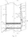
- Figure 3 is an example of an assembly 1 according to another embodiment of the invention, where first and second elements 11, 12 are arranged in the channel 42, and the assembly has activation means 80 in a structure 70 (a wall structure) for activating the assembly. Upon activation, a passageway 71 in the structure 70 is opened for accessing the interior 60 of the set of elements 11, 12. The first and second elements 11, 12 are corrodible, and are shown prior to being destroyed.
- the activation means 80 is in the form of a pressure-destructible member 81 which is disposed in the structure 70 and blocks the passageway 71.
- the structure 70 in this example includes a housing 16 arranged on a periphery of and separate from the main bore 7.
- the pressure-destructible member 81 is therefore disposed on the periphery so that it does not interfere in the main bore 7 itself. Instead, it is mounted in the separate passageway 71 inside the housing 16.
- the passageway 71 in the housing 16 is arranged to connect between the region 21 on an upper side of the element 11 in the channel 43 and the interior 60 of the set of elements in the main bore 7.
- the pressure-destructible member 81 can be destroyed to activate the assembly by applied pressure so that fluid communication between the first region 21 and the interior 60 is obtained via the passageway 71.
- tubing fluid 5 in the region 21 can then pass through the passageway 71 in the wall structure 70 to access the interior 60, where it can come into contact with the contact surfaces 61, 62 of the corrodible elements 11,12 in the main bore 7, thereby causing the elements 11, 12 to corrode and be destroyed such that the main bore 7 between regions 21, 23 is opened up.
- the tubing fluid 5 is brine, which is a mixture of water and salt, comprising in the range of 10-30 mol% salt.
- the salt may typically be sodium chloride, but other salts may also be used.
- the brine is suitable for corroding the material of the elements 11, 12.
- the corrodible elements 11, 12 may be corroded by means of corrosive fluid comprising acid.
- the tubing fluid 5 in the region 21 is used both to destroy the pressure destructible member 81 and the elements 11, 12 (by at least partially dissolving them).
- an activation event takes place, in which the member 81 is destroyed by pressure exerted by the tubing fluid 21 against the upper surface of the member 81 when the pressure exceeds pre-determined pressure threshold.
- the pressure-member 81 can be a so-called burst member, e.g. a glass disc, which breaks when exposed to pressure, e.g. when the pressure reaches a certain threshold or when a certain number of pressure pulses over a certain threshold has been applied to it.
- the tubing fluid 5 can access the interior 60 so as to allow the tubing fluid 5 to come into contact with the corrodible elements 11, 12 in the interior 60.
- the tubing fluid 5 as a result of coming into contact with the elements 11, 12, causes them to corrode.
- the tubing fluid 5 is configured to be exposed to a material of the first and second elements 11, 12 at the contact surfaces 61, 62 so that the material can be corroded by the tubing fluid and the elements 11, 12 destroyed.
- the passageway 71 can be configured somewhat independently from the main bore 7.
- the pressure-destructible member 81 can be located in a position outside of the main bore, so as to reside in a separate passageway 71.
- the inner diameter of the passageway 71 in which the pressure-destructible member 81 is placed, within the housing 16, is smaller than that the main bore of the tubular 2.
- the area blocked by the pressure-destructible member 81 is thus relatively small, which can limit the amount of debris that may result from destroying the pressure-destructible member 81. It can be desirable to minimize the amount of debris left in the wellbore, as debris may be troublesome for well operations.
- the placement in the separate structure of the housing 16 can be useful for reducing the debris impact of pressure-destructible components such as glass burst-discs or the like.
- the structure 70 contains a chamber in which inner and outer sidewalls contain the tubing fluid 5 in the structure 70.
- the tubing fluid 5 penetrates through a port 31 in an inner wall of the bore 7 to enter the structure 70.
- An activation event in the form of applied pressure P1 in the tubing fluid 5, e.g. applied in the region 21, may thus be communicated through the fluid in the structure to exert a force against the pressure destructible member 81 sufficient to break and destroy when required, leading to the delivering of the tubing fluid 5 into the interior 60 and destroying the set of elements 11, 12.
- the first element 11 in the channel 42 has a main body of corrodible material which will corrode upon exposure of the contact surface to the tubing fluid 5 on the underside of the element 11 (when in interior 60), and has a layer of surface coating 131 applied to the main body of corrodible material on the upper side.
- the surface coating 131 is non-reactive, such that it can be exposed to the tubing fluid 5 in the region 21 above the corrodible second barrier 12 without undesired deterioration, and so that the tubing fluid 5 in the region 21 does not come into contact with the corrodible material.
- the chamber in the interior 60 contains a preservative 91 which hinders the dissolution of the material of the elements 11, 12, before desirable to do so. Destruction of the member 81 in the passageway is necessary in order to corrode the elements 11, 12 in the channel 42, since only then can the tubing fluid 5 reach the material of the elements 11, 12 at the contact surfaces 61, 62 to cause them to corrode.
- the preservative 91 preserves a condition of the material of the elements 11, 12, so that the material does not corrode undesirably before the first barrier is destroyed and the tubing fluid 5 can access the region 22.
- the preservative 91 is distilled water. The water fills the chamber in the interior 60 to contact the elements 11, 12. Hence, the corrodible material cannot corrode in the initial configuration as shown in Figure 3 where first and second elements 11, 12 are intact, because of the protective presence of the distilled water.
- the tubing fluid 5 mixes with the distilled water in the interior 60, and the elements 11, 12 are exposed at the contact surfaces to the mixture which is of a composition which causes the corrodible material elements 11, 12 to corrode. In this way, the onset of the process of corroding the elements 11, 12 can be controlled until the proper time.
- the interior 60 contains a reactant for producing a corrosive substance for corroding the material when the tubing fluid 5 accesses the interior and mixes with the reactant.
- the provision of tubing fluid 5 might not on its own be capable of or be sufficient for corroding the material of the elements 11, 12. The reactant does not corrode the material of the elements 11, 12 until the tubing fluid 5 accesses the interior 60.
- the interior contains both a preservative for preserving the material in a configuration prior to activation and a reactant for producing the substance for corroding the material upon mixture with the tubing fluid 5 after activation and when the pressure-destructible member 81 is destroyed.
- the channel 42 will initially be closed between the first and second regions 21, 23, due to the presence of the set of elements 11, 12. This, in effect separates the regions 21, 23, until the elements 11, 12 are destroyed in response to destroying the pressure-destructible member 81.
- the pressure P 1 applied in the region 21 of the tubular, above the elements 11, 12, is increased.
- the pressure P 1 is transmitted to the member 81 and causes it to break.
- the tubing fluid 5 flows and accesses the interior 60 through the passageway 71, and due to its corrosive properties, the tubing fluid 5 corrodes the material of the first and second elements from the interior 60, degrading the elements until they are destroyed.
- the channel 42 is thereby opened up.
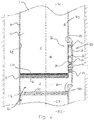
- FIG 4 a variant of the assembly of Figure 3 is depicted where a pressure-communicating device 17 is mounted in the passageway of the structure 70.
- the pressure-communicating device 17 allows fluid and pressure communication into the passageway 71 from the region 21 in the bore 7, but prevents passage for example of particles or debris above a certain size or of undesired composition which may be contained in the fluid in the main bore 7. Such particles are thus prevented from passing through the passageway 71 by the pressure-communicating device 17.
- the tubing fluid 5 which is to be used for corroding the elements 11, 12 can be kept clean so as to ensure it is in good condition.
- Positioning the pressure-communicating device 17 near the port 31 may also prevent any unwanted debris from clogging the passageway 71.
- FIG 5 another variant of the assembly of Figure 3 is depicted.
- the assembly in Figure 5 has the same configuration except that a dedicated, predefined corrosive fluid 18 is contained in the structure 70, separate from the main bore 7.
- the corrosive fluid 18 can be tailored to have properties which are advantageous for controlling corrosion of the elements 11, 12 (when they are to be destroyed). For instance, it may have a particular concentration of active ingredient, a particular volume to correspond with the area of the corrodible material that is to be exposed, or a particular composition.
- the corrosive fluid 18 may thus have a different condition to that of the tubing fluid 5 in the main bore 7, and may be useful for example when it is sought to apply tubing fluid 5 in the main bore 7 of one composition but corrosive fluid 18 of a different composition for corroding the material of the first and second elements 11, 12. This may be useful if the tubing fluid 5 cannot be relied upon to corrode the elements 11, 12 effectively.
- the corrosive fluid 18 interfaces with the tubing fluid 5 in the main bore 7 through the port 31 in the wall of the channel, such that there is pressure communication from the main bore 7 through to the destructible member 81. In this case, the interfacing is through a fluid interface between the corrosive fluid 18 and the tubing fluid 5, although in other variants there may be a membrane (which transmits pressure) interfacing between the tubing fluid 5 and the corrosive fluid 18.
- the pressure of the tubing fluid 5 in the main bore 7 is increased and is transmitted through the corrosive fluid 18 against the pressure-destructible member 81.
- the pressure-destructible member 81 breaks in response to the applied pressure event e.g. when it is sufficiently high or after a certain number of pulses, so as to activate the assembly, obtaining thereby the active configuration.
- the corrosive fluid 18 then travels through the passageway 71 inside the structure 70 and into the interior 60 of the set of elements 11, 12.
- the corrosive fluid 18 enters the interior 60 through a port 32 in the wall of the tubular 2 beneath (i.e.
- an assembly 1 is exemplified where the activation means 80 has a first, pressure destructible member 81 and a second, corrodible member 82.
- the first and second members 81, 82 are spaced apart from one another and provide independent fluid isolating barriers in a double barrier configuration in a wall structure 70 of a tubular body of the tubular 2, separate from the main bore 7. More specifically, the first and second members 81, 82 are both disposed in a passageway 71 within the structure 70, as shown in Figure 6 initially preventing fluid communication through the passageway 71 and into the interior 60.
- the channel 42 has first and second elements 11, 12 arranged therein as described in above described embodiments.
- the wall structure 70 has a dedicated corrosive fluid 18 contained therein in a first section 27 of the structure 70.
- the first section 27 has circumferential sidewalls formed by the tubular 2 and a floor formed by the pressure-destructible member 81, e.g. a glass burst body.
- the wall structure 70 provides a passageway 71 between a port 31 in the wall of the main bore 7 above the element 11 and a port 32 to the interior 60 in the wall of the bore 7 between the elements 11 and 12.
- a pressure-communicating device 17 is also provided in the structure 70, acting as a roof in the first section 27 in which the corrosive fluid 18 is initially contained.
- a dedicated corrosive fluid 18 is provided, once the pressure-destructible first member 81 has been destroyed, the corrosive fluid 18 will travel through the passageway 71 into the second section 29 of the structure to corrode the second member 82. As a result, some tubing fluid 5 from the region 21 in the main bore 7 may pass into the passageway 71 due to pressurisation and penetrate through the pressure-communicating device 17. The pressure-communicating device 17 may then operate to prevent particles from the tubing fluid 5 from entering further into the passageway 71 to help maintain condition of the corrosive fluid 18 in passageway.
- a preservative fluid 91 for preserving the condition of the corrodible second member 82 is contained in the second section 29 of the structure 70, between the first and second members 82, 82.
- the second section 29 comprises a chamber having sidewalls of the housing 16, with the second member 82 providing a floor and the first member 81 providing a roof.
- the first member 81 and the second member 82 of the assembly 1, as well as the pressure-communicating device 17 are located in the housing 16.
- the preservative fluid 91 is a fluid that does not react with the material of the second member 82, to prevent the second member 82 from dissolving in the initial configuration, prior to destroying the members 81, 82.
- the corrosive fluid 18 will mix with the fluid 91.
- the characteristics of the corrosive fluid 18 and the preservative fluid 91 must be such that a mixture of the two will be able to corrode the element 82.
- the pressure-communicating device 17 may therefore preferably be in the form of a piston, a rubber bellow, membrane, or other objects having a pressure-conveying ability.
- the Figure 6 configuration may be advantageous as, prior to any destruction of any of the elements in the channel 42 or members in the passageway 71, the wall structure 70 defines closed chambers in different sections 27, 29 of the structure 70.
- the closed chambers may preferably be small to restrict the volume of the fluid 19 in the two chambers that the corrosive fluid 18 will mix with when destroying them to open up.
- the volume and other characteristics of the corrosive fluid 18 is such that dilution of the corrosive fluid 18 from mixing with the preservative fluid 91, and any fluid in the region 22 does not remove its function as a corrosive, i.e. that the corrosive fluid 18 will still cause second member 82 (and optionally the elements 11, 12) to corrode.
- the volume of fluid contained in the first section 27 may therefore be greater than it appears in Figure 7 , and other similar figures.
- the housing 16 in particular embodiments of the invention may extend circumferentially around the tubular body of the tubing 2 outside the channel 42 in the main bore 7.
- a tubular 2 comprising a tubular body is inserted in a wellbore 8, having an annulus 9 between a wall of the wellbore 8 and an outside of the tubular body.
- the assembly 1 in this example also includes the set of elements 11, 12 disposed in the channel 42 as in examples described above.
- the elements 11, 12 each of them acting as fluid isolators are corrodibly destructible in order to open up the channel 42.
- the first element 11 is mounted to the tubular body in the main bore 7 of the tubing 2, extending across the full diameter of the main bore 7 and isolating the region 23 from the interior 60.
- the second element 12 is mounted to the tubular body in the main bore 7 of the tubing 2, extending across the full diameter of the main bore 7 and isolating the region 21 from the interior 60.
- the assembly 1 includes a structure 70 having a pressure destructible member 81 which is mounted in an entrance of a port 32 in the wall of the tubular body.
- the port 32 provides a passageway 71 for accessing the interior 60 of the set of elements 11, 12.
- the pressure-destructible member 81 in Figure 7 is arranged so as to prevent fluid communication from the annulus 9 into the interior 60 via the port 32
- the pressure of wellbore fluid 10 in the annulus 9 is increased and applied so as to exert a force against the pressure destructible member 81, which is typically a glass burst body, causing it to break. This activates the assembly.
- the fluid 10 from the wellbore annulus enters through the port 32 into the interior 60 of the set of elements 11, 12 and destroys the elements 11, 12 by causing the material of the elements 11, 12 at the contact surfaces to corrode. Over a period of time, the elements 11, 12 degrade to the point where they no longer can function to block the channel 42.
- the channel 42 is opened up between the first and second regions 21, 23.
- the wellbore fluid 10 may thus have characteristics that makes it react with a corrodible material of the elements 11, 12.
- This example can be advantageous in that the pressure P 2 in the wellbore can be applied to destroy the pressure destructible member 81 and then the fluid can destroy the elements 11, 12 in the channel independently of pressure and fluid conditions of the tubing fluid 5.
- the pressure destructible member 82 prevents access to the interior through the port 32.
- a pressure-communicating device 17 may be provided in front of the pressure-destructible barrier 11 on the annulus side.
- the pressure may be applied in the wellbore above a certain threshold or by a plurality of pressure pulses with pressure above a certain threshold.
- Removing the corrodible elements 11, 12 can be done by exposing them to a corrosive substance which acts to corrode a material of the corrodible barrier.
- a pressure-destructible member 81 prevents the corrosive fluid 18 from reaching the corrodibly destructible member 82 or the corrodibly destructible elements 11, 12 in the channel 42, the destruction of these may automatically follow the destruction of the first barrier 11.
- the material of the corrodible member 82 may also be aluminium or aluminium alloy, and the corrosive fluid 18 a saline solution, e.g. a sodium chloride solution, for corroding the aluminium or aluminium alloy.
- a pressure-destructible barrier can also take other forms.
- a pressure sensitive "switch” may be activated by applied pressure and initiate removal of the barrier e.g. by an explosive charge or the like in or near the barrier structure.
- the pressure-destructible member 81 can be replaced by other destructible members that provide for remote activating the structure to open up access to the interior of the elements in the channel 42. Burst members can however be convenient options.
- the pressure-destructible member 81 could for instance be replaced with a destructible member such as dissolvable or corrodible member which may be destroyed, e.g. degraded, by changing the substance of fluid, e.g. in the wellbore, to which a material of the destructible member is exposed to.
- the elements may be destructible by dissolving them. Such further embodiments can for example take the same form as the embodiments described above except that the corrodible elements are dissolvable elements. Any reference to corrosion can thus be replaced with reference to dissolution.
- the elements may be eroded by contact and action of the substance against the contact surfaces.
Landscapes
- Geology (AREA)
- Life Sciences & Earth Sciences (AREA)
- Engineering & Computer Science (AREA)
- Mining & Mineral Resources (AREA)
- Environmental & Geological Engineering (AREA)
- Fluid Mechanics (AREA)
- Physics & Mathematics (AREA)
- General Life Sciences & Earth Sciences (AREA)
- Geochemistry & Mineralogy (AREA)
- Chemical & Material Sciences (AREA)
- Chemical Kinetics & Catalysis (AREA)
- General Chemical & Material Sciences (AREA)
- Detergent Compositions (AREA)
Priority Applications (1)
| Application Number | Priority Date | Filing Date | Title |
|---|---|---|---|
| EP18175338.5A EP3575545A1 (fr) | 2018-05-31 | 2018-05-31 | Ensemble destiné à être utilisé dans un puits de forage et procédé associé |
Applications Claiming Priority (1)
| Application Number | Priority Date | Filing Date | Title |
|---|---|---|---|
| EP18175338.5A EP3575545A1 (fr) | 2018-05-31 | 2018-05-31 | Ensemble destiné à être utilisé dans un puits de forage et procédé associé |
Publications (1)
| Publication Number | Publication Date |
|---|---|
| EP3575545A1 true EP3575545A1 (fr) | 2019-12-04 |
Family
ID=62495618
Family Applications (1)
| Application Number | Title | Priority Date | Filing Date |
|---|---|---|---|
| EP18175338.5A Withdrawn EP3575545A1 (fr) | 2018-05-31 | 2018-05-31 | Ensemble destiné à être utilisé dans un puits de forage et procédé associé |
Country Status (1)
| Country | Link |
|---|---|
| EP (1) | EP3575545A1 (fr) |
Citations (4)
| Publication number | Priority date | Publication date | Assignee | Title |
|---|---|---|---|---|
| US8276670B2 (en) * | 2009-04-27 | 2012-10-02 | Schlumberger Technology Corporation | Downhole dissolvable plug |
| US20140174757A1 (en) * | 2012-08-31 | 2014-06-26 | Halliburton Energy Services, Inc. | Electronic rupture discs for interventionaless barrier plug |
| US20140332233A1 (en) | 2013-05-07 | 2014-11-13 | Halliburton Energy Services, Inc. | Method of removing a dissolvable wellbore isolation device |
| US20160281455A1 (en) * | 2013-03-18 | 2016-09-29 | Tco As | Crushable plug |
-
2018
- 2018-05-31 EP EP18175338.5A patent/EP3575545A1/fr not_active Withdrawn
Patent Citations (4)
| Publication number | Priority date | Publication date | Assignee | Title |
|---|---|---|---|---|
| US8276670B2 (en) * | 2009-04-27 | 2012-10-02 | Schlumberger Technology Corporation | Downhole dissolvable plug |
| US20140174757A1 (en) * | 2012-08-31 | 2014-06-26 | Halliburton Energy Services, Inc. | Electronic rupture discs for interventionaless barrier plug |
| US20160281455A1 (en) * | 2013-03-18 | 2016-09-29 | Tco As | Crushable plug |
| US20140332233A1 (en) | 2013-05-07 | 2014-11-13 | Halliburton Energy Services, Inc. | Method of removing a dissolvable wellbore isolation device |
Similar Documents
| Publication | Publication Date | Title |
|---|---|---|
| US10309183B2 (en) | Internally degradable plugs for downhole use | |
| US9441437B2 (en) | Electronic rupture discs for interventionless barrier plug | |
| RU2372470C2 (ru) | Способ создания временного барьера на пути движения потока (варианты) | |
| US9441446B2 (en) | Electronic rupture discs for interventionaless barrier plug | |
| CA2143349C (fr) | Commande hydraulique pour outils a expansion inseres dans un puits | |
| US5425424A (en) | Casing valve | |
| US3245472A (en) | Duct-forming devices | |
| AU2014346622A1 (en) | Internally degradable plugs for downhole use | |
| US10358892B2 (en) | Sliding sleeve valve with degradable component responsive to material released with operation of the sliding sleeve | |
| OA12336A (en) | Method for treating multiple wellbore intervals. | |
| EA034040B1 (ru) | Выравнивающий давление клапан для инструмента обработки | |
| CA2994780A1 (fr) | Outil de fond de puits | |
| US20110094754A1 (en) | Wellbore treatment apparatus and method | |
| WO2006059066A1 (fr) | Outil de derivation | |
| US11613959B1 (en) | Wiper plug with atmospheric chamber | |
| EP3575545A1 (fr) | Ensemble destiné à être utilisé dans un puits de forage et procédé associé | |
| US20180119508A1 (en) | Degradable elements for downhole applications | |
| US20140069647A1 (en) | Cased Hole Chemical Perforator | |
| EP3085883A1 (fr) | Train d'outils de fond pour bouchon et abandon par agent corrosif | |
| CA3010364C (fr) | Ensemble bouchon de rupture avec piece rapportee d'etranglement, outil de fracturation et procede de fracturation l'utilisant | |
| US20220290040A1 (en) | Using acidic balls for acid stimulation in carbonate reservoirs | |
| US20230304373A1 (en) | Degradable Plug Device For A Pipe | |
| US20230175344A1 (en) | Modified cement plug and methods of use | |
| US11339621B2 (en) | Systems and methods for bonding a downhole tool to a surface within the borehole | |
| WO2023214175A1 (fr) | Procédés d'élimination de bouchons en alliage et de joints annulaires et appareil associé |
Legal Events
| Date | Code | Title | Description |
|---|---|---|---|
| PUAI | Public reference made under article 153(3) epc to a published international application that has entered the european phase |
Free format text: ORIGINAL CODE: 0009012 |
|
| AK | Designated contracting states |
Kind code of ref document: A1 Designated state(s): AL AT BE BG CH CY CZ DE DK EE ES FI FR GB GR HR HU IE IS IT LI LT LU LV MC MK MT NL NO PL PT RO RS SE SI SK SM TR |
|
| AX | Request for extension of the european patent |
Extension state: BA ME |
|
| STAA | Information on the status of an ep patent application or granted ep patent |
Free format text: STATUS: THE APPLICATION IS DEEMED TO BE WITHDRAWN |
|
| 18D | Application deemed to be withdrawn |
Effective date: 20200605 |