EP3575504A1 - Flow channel for an inspection chamber or man-hole - Google Patents
Flow channel for an inspection chamber or man-hole Download PDFInfo
- Publication number
- EP3575504A1 EP3575504A1 EP19176998.3A EP19176998A EP3575504A1 EP 3575504 A1 EP3575504 A1 EP 3575504A1 EP 19176998 A EP19176998 A EP 19176998A EP 3575504 A1 EP3575504 A1 EP 3575504A1
- Authority
- EP
- European Patent Office
- Prior art keywords
- flow channel
- inlet
- outlet
- man
- plates
- Prior art date
- Legal status (The legal status is an assumption and is not a legal conclusion. Google has not performed a legal analysis and makes no representation as to the accuracy of the status listed.)
- Granted
Links
Images





Classifications
-
- E—FIXED CONSTRUCTIONS
- E03—WATER SUPPLY; SEWERAGE
- E03F—SEWERS; CESSPOOLS
- E03F5/00—Sewerage structures
- E03F5/02—Manhole shafts or other inspection chambers; Snow-filling openings; accessories
- E03F5/021—Connection of sewer pipes to manhole shaft
-
- E—FIXED CONSTRUCTIONS
- E03—WATER SUPPLY; SEWERAGE
- E03F—SEWERS; CESSPOOLS
- E03F5/00—Sewerage structures
- E03F5/02—Manhole shafts or other inspection chambers; Snow-filling openings; accessories
-
- B—PERFORMING OPERATIONS; TRANSPORTING
- B29—WORKING OF PLASTICS; WORKING OF SUBSTANCES IN A PLASTIC STATE IN GENERAL
- B29C—SHAPING OR JOINING OF PLASTICS; SHAPING OF MATERIAL IN A PLASTIC STATE, NOT OTHERWISE PROVIDED FOR; AFTER-TREATMENT OF THE SHAPED PRODUCTS, e.g. REPAIRING
- B29C53/00—Shaping by bending, folding, twisting, straightening or flattening; Apparatus therefor
- B29C53/02—Bending or folding
- B29C53/04—Bending or folding of plates or sheets
-
- E—FIXED CONSTRUCTIONS
- E02—HYDRAULIC ENGINEERING; FOUNDATIONS; SOIL SHIFTING
- E02D—FOUNDATIONS; EXCAVATIONS; EMBANKMENTS; UNDERGROUND OR UNDERWATER STRUCTURES
- E02D29/00—Independent underground or underwater structures; Retaining walls
- E02D29/12—Manhole shafts; Other inspection or access chambers; Accessories therefor
-
- E—FIXED CONSTRUCTIONS
- E02—HYDRAULIC ENGINEERING; FOUNDATIONS; SOIL SHIFTING
- E02D—FOUNDATIONS; EXCAVATIONS; EMBANKMENTS; UNDERGROUND OR UNDERWATER STRUCTURES
- E02D29/00—Independent underground or underwater structures; Retaining walls
- E02D29/12—Manhole shafts; Other inspection or access chambers; Accessories therefor
- E02D29/124—Shaft entirely made of synthetic material
-
- E—FIXED CONSTRUCTIONS
- E03—WATER SUPPLY; SEWERAGE
- E03F—SEWERS; CESSPOOLS
- E03F5/00—Sewerage structures
- E03F5/02—Manhole shafts or other inspection chambers; Snow-filling openings; accessories
- E03F5/024—Manhole shafts or other inspection chambers; Snow-filling openings; accessories made of plastic material
-
- E—FIXED CONSTRUCTIONS
- E03—WATER SUPPLY; SEWERAGE
- E03F—SEWERS; CESSPOOLS
- E03F5/00—Sewerage structures
- E03F5/02—Manhole shafts or other inspection chambers; Snow-filling openings; accessories
- E03F5/027—The bottom made of prefabricated segments
Definitions
- the present invention relates to a flow channel for an inspection chamber or man-hole.
- the present invention relates to a use of a flow channel.
- the present invention relates to an inspection chamber or man-hole.
- the present invention relates to a method of manufacturing a flow channel for an inspection chamber or man-hole.
- the present invention relates to a computer readable memory.
- Inspection chambers or man-holes are known by means of which a person can have access to a sewer system, a storm water removal system, a system for processing or transporting liquids, and the like.
- the inspection chambers or man-holes are normally used for providing access to a flow channel for reasons of inspection, maintenance, cleaning, de-clogging, and the like.
- Said inspection chambers or man-holes are typically buried into the ground, for example below the tarmac of a street or below a walkway.
- Conventional systems employed for handling sewage, storm drainage and the like employ vertically oriented inspection chambers or manholes of generally cylindrical shape which are positioned at juncture locations of diverse flow pipes or at positions where flow pipes change their orientation.
- the inspection chambers or man-holes typically include a cover which can be manually removed in order to provide access to a respective inspection chamber or man-hole.
- Each inspection chamber or man-hole comprises at least two flow openings or sewage water openings, i.e. at least one inlet opening for inwardly flowing material and at least one outlet opening for outwardly flowing material.
- An inflow pipe is connected to each inlet opening and an outflow pipe is connected to each outlet opening.
- sewer pipes may be connected to the inspection chamber or man-hole.
- Inflow pipes frequently arrive at different elevations and are frequently of different sizes.
- outflow pipes frequently depart at different elevations and are frequently of different sizes.
- Document US 4867411 A discloses a plurality of invert forming mold members which are bolted together and have their ends received in internal frames provided at adjacent pipe openings in a manhole.
- the mold members are formed of relatively thick and heavy polyurethane and are of U-shaped cross-section.
- a mold supporting plate is provided in each of the internal mounting frames and has an opening configured to matingly receive the endmost mold component.
- the mold components are provided in a variety of linear lengths, angular curved configurations and elevation changing members so that they can be associated to form inverts required for any particular manhole configuration.
- the assembly of mold members is strong and rigid and does not require any additional internal bracing.
- document US 2008/141445 A describes an inspection chamber having a plastic sleeve as well as a plastic base attached to the sleeve and provided with at least two openings to which a pipe can in each case be attached.
- the plastic base has a flow profile which extends between the openings, and is made up of at least two separate base parts which, at the edges thereof facing towards each other, are fixedly attached to one another by means of a joining technique, such as gluing, welding and/or pop rivets.
- document US 2005/161088 A teaches a manhole base or liner for directing the flow of liquid from a manhole inlet opening positioned in one of a plurality of possible locations in a manhole side wall to a manhole outlet opening in the manhole side wall, and a manhole having the base or liner.
- the base or liner includes a perimeter, an upper surface extending to the perimeter, and a liquid flow path formed in the upper surface.
- the liquid flow path has, in series, first and second flow path portions, the first flow path portion defined by a first bottom wall and a pair of spaced apart side by side guide walls extending upwardly from the bottom wall, the guide walls each having a guide wall inner end and a guide wall outer end, the outer ends being located at the perimeter and being spaced apart a greater distance than the distance between the inner ends, the second flow path portion being defined by a second bottom wall, contiguous with the first bottom wall, and a pair of spaced apart side by side channel walls extending upwardly from the second bottom wall, each channel wall having an inner channel wall end and an outer channel wall end, the inner channel wall ends meeting the respective guide wall inner ends, and the outer channel wall ends being located at the perimeter.
- Document EP 1174550 A2 discloses a base element for a manhole shaft.
- the lower section of a shaft using prefabricated parts, has at least two channel segments assembled into an inner body with an outflow connection and at least one inflow connection.
- the inner body, with the component parts fitted together, is embedded into a lower part body with its base and mantle, so that the inflow and outflow connections match up with the inflows and outflows at the lower body.
- a modular system forming an inspection chamber or manhole for a drainage system comprises a base portion, an insert portion adapted to lie at least partly upon said base and having one or more drainage channels fabricated within it, a plurality of support segments of desired arc lengths, the insert portion being supported at its edges between the top of the support segments and a stack of shaft rings, wherein each piece is preformed and the structure is adapted to be assembled in situ and to be connected to the ends of drainage pipes.
- a manhole comprises an access chamber of moulded plastics material with a closed bottom and inlet forming portions spaced around the lower end of the sides of the chamber and an invert-forming insert of moulded plastics material fitting in the bottom of the chamber and having at least one upwardly facing channel forming an invert between two of the inlet forming portions.
- the insert is a tight fit in the chamber bottom with its sides blocking off the unused inlets and is snapped past an inward projection just above the inlets.
- the insert may be either a closed body with a bottom or it may be an open shell reinforced by ribs at locations not bearing invert channels.
- the inlet forming portions may be knock outs in the chamber wall, sealing being effected round a pipe-end inserted in a knocked out hole by means of a grommet or the ends of the outwardly projecting blind spigots may be pierced or cut off to provide access.
- the upper end of the chamber is formed as a socket to receive an extension piece with an outward flange for contacting a manhole cover. Additional socketing extension pieces may be provided between the chamber and extension piece.
- the chamber, extensions and insert may be of octagonal or circular cross-section and the chamber may serve simply as a former surrounded in use by low grade concrete or other settable filler or by a built-up structure.
- Document US 2007/053750 A describes an inspection chamber having a plastic sleeve, a plastic base accommodated in the sleeve and at least two branches connected to the sleeve, which base has a flow profile that extends between the two branches.
- the base is made up of at least two separate base parts that are permanently fixed to one another at their edges facing one another, such as by welding, fusing, gluing and the like.
- JP 6026065 A discloses an invert block structure for a manhole.
- JP 6146313 A teaches an invert block for a man-hole and a driving channel formation method.
- JP 5287766 A describes further an invert manufacturing method of a sewage man-hole. According to the method, concrete is poured into a form consisting of male and female types to form an invert, and precasting the invert takes place at a plant other than a man-hole construction site.
- a flow channel for an inspection chamber or man-hole comprising at least one inlet configured to be coupled to at least one inlet pipe, at least one outlet configured to be coupled to at least one outlet pipe, and wherein the flow channel between the at least one inlet and the at least one outlet is formed by at least one bent plate.
- the plate preferably comprises a weldable material, such as a metal or, in particular, a thermoplastic material. By welding, two or more bent and/or planar plates can be joined to form even complex surface profiles.
- an inspection chamber or man-hole comprising a base, a perimeter wall protruding from the base, a flow channel comprising at least one inlet configured to be coupled to at least one inlet pipe, at least one outlet configured to be coupled to at least one outlet pipe, and wherein the flow channel between the at least one inlet and the at least one outlet is formed by at least one bent plate, and a frame positioned on the base and configured to support the bent plate.
- a method of manufacturing a flow channel for an inspection chamber or man-hole comprising measuring or determining information including at least diameters, orientations and depths of at least two pipes in the ground, cutting of at least one flat plate into a defined shape based on the measured or determined information, and bending the at least one cut plate into a predefined form.
- a non-transitory computer readable memory medium having stored thereon a set of computer readable instructions that, when executed by at least one processor, cause a system to at least receive measured or determined information including diameters, orientations and depths of at least two pipes in the ground, calculate a defined shape for at least one flat plate based on the received information, wherein the flat plate is configured to be bent into a predefined form in order to form a flow channel for an inspection chamber or man-hole, transmit calculated shape data for the at least one flat plate to a CNC machine, and cause the CNC machine to cut the at least one flat plate into the defined shape.
- a flow channel for an inspection chamber or man-hole a use of a flow channel in connection with an inspection chamber or man-hole, an inspection chamber or man-hole, a method of manufacturing a flow channel for an inspection chamber or man-hole, and a computer readable memory are provided.
- Flow channels of different inspection chambers or man-holes are typically not identical, because of varying parameters such as number of inlet pipes, number of outlet pipes, diameter of inlet pipes, diameter of outlet pipes, orientation of inlet pipes, orientation of outlet pipes, depth in the ground of inlet pipes, depth in the ground of outlet pipes, distance between inlet and outlet pipes, depth difference between inlet and outlet pipes, and the like.
- flow channels are provided for different inspection chambers or man-holes having various parameters. Forming of each flow channel can be carried out quickly and easily, for example when building a sewer system or replacing an existing inspection chamber or man-hole by a new one and connecting it with existing pipes in the ground.
- complex flow channels can be formed by a low number of bent plates. For example, only two plates are required to connect two inlet pipes with a single outlet pipe. Even more complex flow channels can be formed with a very low number of plates.
- the flow channels are lightweight and the dimensions can be freely selected. Non-standardized flow channels can be provided. Flow channels for any dimensions of pipes and material of the respective pipes can be provided.
- flat or planar plates can be cut into a defined shape in a plant based on measured or determined information and/or parameters.
- the plates are typically cut into the defined shape based on a computer calculation.
- the shape of the plates is typically calculated based on the measured or determined input data.
- the defined shape of the plates can be automatically calculated by at least one processing core.
- the defined shape of the plates may be provided as CAD data.
- the plate's mechanical dimensions may be defined using CAD software, and then translated into manufacturing directives by CAM software.
- the resulting directives may be transformed into commands necessary for a CNC machine to cut the plates.
- the CNC machine may cut the plates into the defined shape according to the calculated CAD data.
- the flow channels can be formed at the construction site by manually bending the pre-cut plates into a predefined form and welding them together or connecting the bent plates otherwise.
- the plates may also be cut into the defined shape by another device or even manually.
- flow channel means a flow system through which material such as sewage water and storm drainage can flow.
- the channel is configured to be connected to at least one inlet pipe and at least one outlet pipe.
- the channel is configured to be arranged within an inspection chamber or man-hole.
- the channel is open on one side to provide access to the channel.
- the term "inspection chamber” means a structure by means of which a person can have access to a flow channel positioned within said structure.
- the structure comprises a base, a perimeter wall, at least one inlet opening, at least one outlet opening and an access opening.
- a flow channel is further arranged within the structure.
- the structure is dimensioned such that a person cannot completely enter the structure.
- the term "man-hole” means a structure by means of which a person can have access to a flow channel positioned within said structure.
- the structure comprises a base, a perimeter wall, at least one inlet opening, at least one outlet opening and an access opening.
- a flow channel is further arranged within the structure.
- the structure is dimensioned such that a person can completely enter the structure via the access opening. Entering through the access opening may, for example, take place using a ladder.
- FIGURE 1 a schematic perspective view of a flow channel 1 in accordance with at least some embodiments of the present invention is illustrated.
- the flow channel 1 is shown within an inspection chamber 2.
- Such inspection chambers 2 of a sewage system are, for example, located at a distance of about 40 m - 50 m to each other.
- the inspection chambers 2 are typically connected to each other by sewage pipes.
- an inspection chamber 2 comprising a base 8 and a perimeter wall 9 is shown.
- the inspection chamber 2 further includes an inlet opening and an outlet opening in the perimeter wall 9.
- An inlet pipe 5 is coupled to the inspection chamber 2 on one side and an outlet pipe 7 is coupled to the inspection chamber 2 on an opposite side.
- the flow channel 1 comprises an inlet 4 configured to be coupled to the inlet pipe 5.
- the flow channel further comprises an outlet 6 configured to be coupled to the outlet pipe 7.
- the flow channel 1 between the inlet 4 and the outlet 6 is formed by at least one bent plate 3. In FIGURE 1 , the shown flow channel 1 is straight.
- a support frame 10 is arranged on the base 8 of the inspection chamber 2.
- the frame 10 is configured to support the at least one bent plate 3 forming the flow channel 1.
- the plate 3 is bent into a form corresponding to the form of a part of the frame 10.
- the predefined form of the flow channel 1 is achieved by pressing the plate 3 against parts of the frame 10.
- the bent plate 3 may be at least temporarily attached to the frame using attachment means, for example clips, in order to align the at least one plate 3 and the frame 10 for welding the plate 3 and the frame 10 together.
- the thickness of the at least one bent plate 3 is typically in the range between 3 mm and 30 mm, and thus it is possible to bend the at least one plate 3 manually.
- heating of the at least one plate 3 is not required in order to bend the plate into a predefined form.
- the surface of the plate 3 forming the flow channel 1 is smooth, i.e. there are typically no corners, steps, bumps, and the like.
- the flow channel 1 is normally U-shaped.
- Extension plates 11 are further connected to the at least one bent plate 3.
- the extension plates 11 cover the frame 10 and prevent overflowing of material from the flow channel 1.
- the extension plates and the at least one bent plate 3 are welded together or the extension plates 11 are an integral part of the bent plate 3.
- the at least one bent plate 3 and the extension plates 11 are of the same material, for example thermoplastic material, in particular a polyolefin material, such as polyethylene (PE) or polypropylene (PP).
- suitable thermoplastic materials include weldable thermoplastic materials, such as polystyrene (PS), acrylonitrile butadiene styrene (ABS), polyimide (PI) and polyamide (PA) or a thermoset material.
- the extension plates 11 are further fixedly attached to the frame 10.
- the frame 10 may be of the same material as the at least one plate 3 and the extension plates 11. Thus, all parts forming the flow channel 1 can be welded together.
- the flow channel 1 may also be located within a man-hole instead of the inspection chamber 2.
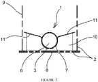
- FIGURE 2 a schematic front view of a flow channel 1 in accordance with at least some embodiments of the present invention is illustrated.
- the flow channel 1 comprises an inlet configured to be coupled to an inlet pipe.
- the flow channel further comprises an outlet 6 configured to be coupled to an outlet pipe 7.
- the flow channel 1 between the inlet 4 and the outlet 6 is formed by a bent plate 3.
- the shown flow channel 1 is straight.
- Extension plates 11 are connected to the bent plate 3.
- the angle between the extension plates 11 and the basis 8 may vary depending on in which country the flow channel 1 is to be installed. Also the distance between the extension plates 11 and the baseline of the bent plate 3 or the lowest point of the plate 3, may vary depending on in which country the flow channel 1 is to be installed. The distance between the extension plates 11 and the baseline of the bent plate 3 or the lowest point of the plate 3 may be, for example, greater than 1/2 of the diameter of the pipe 7.
- FIGURE 3 a schematic side view of a flow channel 1 in accordance with at least some embodiments of the present invention is illustrated.
- the flow channel 1 comprises an inlet 4 configured to be coupled to an inlet pipe 5.
- the flow channel further comprises an outlet 6 configured to be coupled to an outlet pipe 7.
- the flow channel 1 between the inlet 4 and the outlet 6 is formed by a bent plate 3.
- the shown flow channel 1 is straight.
- the inlet 4 and the outlet 6 may be configured to be coupled to pipes 5, 7 having a diameter of 110 mm or greater than 110 mm, for example to pipes 5, 7 having a diameter in the range between 110 mm and 3000 mm.
- FIGURE 4 a schematic perspective view of another flow channel 1 in accordance with at least some embodiments of the present invention is illustrated.
- the flow channel 1 comprises an inlet 4 configured to be coupled to an inlet pipe 5.
- the flow channel further comprises an outlet 6 configured to be coupled to an outlet pipe 7.
- the flow channel 1 between the inlet 4 and the outlet 6 is formed by a plurality of bent plates 3.
- the shown flow channel 1 is not straight.
- the flow channel 1 changes its orientation by about 30 degrees.
- the bent plates 3 are welded together along a welding line 12. Extension plates 11 are further welded to the bent plates 3 as well as to each other on each side of the flow channel 1.
- the orientation of the flow channel 1 changes at the welding line 12. Typically, the orientation changes by 30 degrees or less. Thus, material cannot get stuck and clogging of the flow channel 1 can be avoided.
- the orientation of the first part of the flow channel 1 is identical with the orientation of the inlet pipe 5 and the orientation of the second part of the flow channel 1 is identical with the orientation of the outlet pipe 7.
- the orientation of the flow channel only changes once.
- the orientation of the flow channel can change several times, for instance.
- the orientation of the first part of the flow channel 1 is not identical with the orientation of the inlet pipe 5 and/or the orientation of the second part of the flow channel 1 is not identical with the orientation of the outlet pipe 7.
- adjacent plates 3 may be fixedly attached to each other using adhesive.
- adhesive refers to a material, by means of which plates 3, extension plates 11 and/or the frame 10 can be attached to each other.
- the adhesive used in the embodiments may be, for example, an epoxy.
- the adhesive used is selected in such a way that the adhesive used will have sufficient adhesion to the plates 3, extension plates 11 and/or the frame 10. According to certain embodiments, the adhesive selected has a short hardening time, such as a few seconds or less than a minute at most.
- the adhesive hardens at least partly within this time so that the adhesive will be able to hold the plates 3, extension plates 11 and/or the frame 10 in place.
- the final hardening can take clearly more time and the final hardening can even be planned to take place in connection with later process stages.
- adjacent plates 3, extension plates 11 and/or the frame 10 may be attached to each other by mechanical joints. Adjacent plates may, for example, include tongue and groove joints or other mechanical connections. Adhesive may be additionally used in order to seal the joint to avoid leaking of the flow channel 1.
- the flow channel 1 may also be located within a man-hole instead of the inspection chamber 2.
- FIGURE 5 a schematic front view of another flow channel 1 in accordance with at least some embodiments of the present invention is illustrated.
- the flow channel 1 comprises an inlet 4 configured to be coupled to an inlet pipe 5.
- the flow channel further comprises an outlet 6 configured to be coupled to an outlet pipe 7.
- the flow channel 1 between the inlet 4 and the outlet 6 is formed by bent plates 3.
- the shown flow channel 1 is not straight.
- the flow channel 1 changes its orientation by about 30 degrees.
- FIGURE 6 a schematic side view of another flow channel 1 in accordance with at least some embodiments of the present invention is illustrated.
- the flow channel 1 comprises an inlet 4 configured to be coupled to an inlet pipe 5.
- the flow channel further comprises an outlet 6 configured to be coupled to an outlet pipe 7.
- the flow channel 1 between the inlet 4 and the outlet 6 is formed by bent plates 3.
- the shown flow channel 1 is not straight.
- the flow channel 1 changes its orientation by about 30 degrees at the welding line 12.
- FIGURE 7 a schematic top view of another flow channel 1 in accordance with at least some embodiments of the present invention is illustrated.
- the flow channel 1 comprises an inlet 4 configured to be coupled to an inlet pipe 5.
- the flow channel further comprises an outlet 6 configured to be coupled to an outlet pipe 7.
- the flow channel 1 between the inlet 4 and the outlet 6 is formed by bent plates 3.
- the shown flow channel 1 is not straight.
- the flow channel 1 changes its orientation by about 30 degrees as shown by the angle ⁇ .
- the inlet pipe 5 has a first diameter d 1 and the outlet pipe has a second diameter d 2 .
- the first diameter d 1 and the second diameter d 2 may be identical or different.
- the diameters d 1 , d 2 are identical.
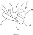
- FIGURE 8 a schematic perspective view of a further flow channel 1 in accordance with at least some embodiments of the present invention is illustrated.
- the flow channel 1 comprises two inlets 4, wherein each inlet 4 is configured to be coupled to a respective inlet pipe 5.
- the flow channel 1 is configured to be coupled to inlet pipes 5 having different orientation.
- the diameters of the inlet pipes 5 may be identical or different according to certain embodiments.
- the flow channel 1 further comprises a single outlet 6 configured to be coupled to an outlet pipe 7, wherein the orientation of the outlet pipe coincides with one of the inlet pipes.
- all pipes 5, 7 may have a different orientation and/or diameter. Additionally, the pipes may arrive and/or depart at different depths in the ground. There is a depth difference between an inlet 4 and an outlet 6 of 1 cm - 2 cm per m length of the flow channel 1, for instance.
- the flow channel 1 between the inlets 4 and the outlet 6 is formed by only two bent plates 3. Within the flow channel 1, a junction is located. Material flowing through the flow channel 1 from the first inlet 4 and from the second inlet 4 can flow towards the outlet 6 from the junction at the welding line 12. In other words, the flows from the first inlet 4 and from the second inlet 4 are combined to be one flow after the junction.
- the flow channel 1 is made by only two bent plates 3.
- the pre-cut plates 3 can be manually bent at the construction site and welded together along welding line 12.
- Extension plates 11 may be additionally welded to the bent plates 3 or be an integral part of the bent plates 3.
- the installation of the flow channel 1 is less time consuming and less labour intensive than e.g. bolting a plurality of U-shaped profiles together.
- FIGURE 9 a schematic front view of a further flow channel 1 in accordance with at least some embodiments of the present invention is illustrated.
- the flow channel 1 comprises two inlets and one outlet 6.
- the flow channel 1 is made by only two bent plates 3.
- FIGURE 10 a schematic top view of two cut plates 3 of a yet further flow channel 1 in accordance with at least some embodiments of the present invention is illustrated.
- Flat plates 3 are cut based on measured or determined information including orientations, diameters and depths in the ground of different pipes.
- the shape of the plates 3 may be defined by a computer calculation based on the measured or determined information. Defined shape data of the plates 3 may then be provided as CAD data.
- the plates 3 may then be cut by a CNC machine into the defined shape.
- a flow channel 1 having two inlets and one outlet can be formed by bending the plates 3 shown in FIGURE 10 against a frame and welding the bent plates 3 together.
- the plates 3 may also be cut by another device, for example a plasma burner, or even manually using a saw.
- the plates 3 may comprise a plurality of grooves in the rear side of the plates 3, i.e. in the side opposite to the side forming the flow channel 1.
- the grooves improve bending of the plates 3 due to locally decreasing the thickness of the plates 3, thus providing some sort of flexibility.
- the grooves may be arranged locally in the rear side, for example only where a small bending radius is required.
- the grooves may also be arranged over the entire rear surface of the plates.
- the grooves may be arranged at identical or varying distances to each other.
- the grooves do not extend to one edge or to the edges of a respective plate 3. Instead, an end of a respective groove is located at a distance of a few millimetres, for example at a distance in the range between 5 mm to 30 mm, from the respective edge of the plate 3.
- welding of two adjacent plates 3 to each other is enhanced, while a sufficient flexibility for bending the plates 3 is still provided.
- the grooves may have identical or different depth, length and/or shape.
- the depth of a groove may be in the range between 10 % and 70 % of the thickness of a respective plate 3, for instance.
- the grooves may have, for example, a depth of 5 mm and the thickness of the plate may be, for example, 10 mm.
- the grooves may be arranged parallel or at an angle to each other.
- the side forming the flow channel is typically smooth.
- At least some embodiments of the present invention find industrial application in forming of a flow channel for an inspection chamber or man-hole as well as in inspection chambers and other subterranean chambers and wells.
Landscapes
- Engineering & Computer Science (AREA)
- Life Sciences & Earth Sciences (AREA)
- Health & Medical Sciences (AREA)
- Hydrology & Water Resources (AREA)
- Public Health (AREA)
- Water Supply & Treatment (AREA)
- Mining & Mineral Resources (AREA)
- General Life Sciences & Earth Sciences (AREA)
- Environmental & Geological Engineering (AREA)
- Paleontology (AREA)
- Civil Engineering (AREA)
- General Engineering & Computer Science (AREA)
- Structural Engineering (AREA)
- Mechanical Engineering (AREA)
- Sewage (AREA)
- Measuring Volume Flow (AREA)
Abstract
Description
- The present invention relates to a flow channel for an inspection chamber or man-hole.
- Further, the present invention relates to a use of a flow channel.
- Yet further, the present invention relates to an inspection chamber or man-hole.
- Furthermore, the present invention relates to a method of manufacturing a flow channel for an inspection chamber or man-hole.
- Additionally, the present invention relates to a computer readable memory.
- Inspection chambers or man-holes are known by means of which a person can have access to a sewer system, a storm water removal system, a system for processing or transporting liquids, and the like. The inspection chambers or man-holes are normally used for providing access to a flow channel for reasons of inspection, maintenance, cleaning, de-clogging, and the like. Said inspection chambers or man-holes are typically buried into the ground, for example below the tarmac of a street or below a walkway. Conventional systems employed for handling sewage, storm drainage and the like employ vertically oriented inspection chambers or manholes of generally cylindrical shape which are positioned at juncture locations of diverse flow pipes or at positions where flow pipes change their orientation. The inspection chambers or man-holes typically include a cover which can be manually removed in order to provide access to a respective inspection chamber or man-hole.
- Each inspection chamber or man-hole comprises at least two flow openings or sewage water openings, i.e. at least one inlet opening for inwardly flowing material and at least one outlet opening for outwardly flowing material. An inflow pipe is connected to each inlet opening and an outflow pipe is connected to each outlet opening.
- Of course, also more than two sewer pipes may be connected to the inspection chamber or man-hole. There may be a plurality of inlet openings and/or a plurality of outlet openings comprised by the inspection chamber or man-hole. Inflow pipes frequently arrive at different elevations and are frequently of different sizes. Also outflow pipes frequently depart at different elevations and are frequently of different sizes.
- When building a sewer system or replacing an existing inspection chamber or man-hole by a new one, it is often not possible to use a standardized inspection chamber or man-hole, because the dimensions of the pipes, the orientations of the pipes and the depths of the pipes in the ground differ on a case by case basis. Therefore, the flow channel within the inspection chamber or man-hole has typically to be adapted accordingly.
- Document
US 4867411 A discloses a plurality of invert forming mold members which are bolted together and have their ends received in internal frames provided at adjacent pipe openings in a manhole. The mold members are formed of relatively thick and heavy polyurethane and are of U-shaped cross-section. A mold supporting plate is provided in each of the internal mounting frames and has an opening configured to matingly receive the endmost mold component. The mold components are provided in a variety of linear lengths, angular curved configurations and elevation changing members so that they can be associated to form inverts required for any particular manhole configuration. The assembly of mold members is strong and rigid and does not require any additional internal bracing. However, a substantial amount of U-shaped members has to be cut into a predetermined form prior to bolting the members together in order to form a flow channel. Therefore, forming of the flow channel requires a substantial number of parts and is time consuming and labour intensive. Due to the high number of U-shaped profiles, there is further a risk that the flow channel will start to leak. - Further, document
US 2008/141445 A describes an inspection chamber having a plastic sleeve as well as a plastic base attached to the sleeve and provided with at least two openings to which a pipe can in each case be attached. The plastic base has a flow profile which extends between the openings, and is made up of at least two separate base parts which, at the edges thereof facing towards each other, are fixedly attached to one another by means of a joining technique, such as gluing, welding and/or pop rivets. - Furthermore, document
US 2005/161088 A teaches a manhole base or liner for directing the flow of liquid from a manhole inlet opening positioned in one of a plurality of possible locations in a manhole side wall to a manhole outlet opening in the manhole side wall, and a manhole having the base or liner. The base or liner includes a perimeter, an upper surface extending to the perimeter, and a liquid flow path formed in the upper surface. The liquid flow path has, in series, first and second flow path portions, the first flow path portion defined by a first bottom wall and a pair of spaced apart side by side guide walls extending upwardly from the bottom wall, the guide walls each having a guide wall inner end and a guide wall outer end, the outer ends being located at the perimeter and being spaced apart a greater distance than the distance between the inner ends, the second flow path portion being defined by a second bottom wall, contiguous with the first bottom wall, and a pair of spaced apart side by side channel walls extending upwardly from the second bottom wall, each channel wall having an inner channel wall end and an outer channel wall end, the inner channel wall ends meeting the respective guide wall inner ends, and the outer channel wall ends being located at the perimeter. - Document
EP 1174550 A2 discloses a base element for a manhole shaft. The lower section of a shaft, using prefabricated parts, has at least two channel segments assembled into an inner body with an outflow connection and at least one inflow connection. The inner body, with the component parts fitted together, is embedded into a lower part body with its base and mantle, so that the inflow and outflow connections match up with the inflows and outflows at the lower body. - Document
WO 93/19258 A1 - Document
GB 1363302 A - Document
US 2007/053750 A describes an inspection chamber having a plastic sleeve, a plastic base accommodated in the sleeve and at least two branches connected to the sleeve, which base has a flow profile that extends between the two branches. The base is made up of at least two separate base parts that are permanently fixed to one another at their edges facing one another, such as by welding, fusing, gluing and the like. - Document
JP 6026065 A JP 6146313 A JP 5287766 A - In view of the foregoing, it would be beneficial to provide a flow channel for various types of inspection chambers or man-holes, wherein forming of the flow channel requires a low number of parts and is less time consuming and less labour intensive.
- The invention is defined by the features of the independent claims. Some specific embodiments are defined in the dependent claims.
- According to a first aspect of the present invention, there is provided a flow channel for an inspection chamber or man-hole, the flow channel comprising at least one inlet configured to be coupled to at least one inlet pipe, at least one outlet configured to be coupled to at least one outlet pipe, and wherein the flow channel between the at least one inlet and the at least one outlet is formed by at least one bent plate. The plate preferably comprises a weldable material, such as a metal or, in particular, a thermoplastic material. By welding, two or more bent and/or planar plates can be joined to form even complex surface profiles.
- Various embodiments of the first aspect may comprise at least one feature from the following bulleted list:
- a first diameter of at least one pipe differs from a second diameter of at least another pipe
- the flow channel between the at least one inlet and the at least one outlet is formed by a plurality of bent plates which are welded together
- the flow channel between the at least one inlet and the at least one outlet is formed by a plurality of bent plates which are attached to each other using adhesive material
- the flow channel between the at least one inlet and the at least one outlet is formed by a plurality of bent plates which are attached to each other using mechanical joints
- the flow channel is straight
- the flow channel is configured to provide a flow connection between at least two pipes having different orientations
- an orientation of the flow channel changes at a welding line between two adjacent welded plates by an angle of 30 degrees or less
- an orientation of the flow channel changes at a position between two adjacent plates by an angle of 30 degrees or less
- the flow channel comprises at least two inlets, wherein each inlet is configured to be coupled to an inlet pipe
- the flow channel comprises at least two outlets, wherein each outlet is configured to be coupled to an outlet pipe
- the flow channel comprises a junction
- the flow channel is configured to be coupled to at least one pipe having a diameter of 110 mm or greater than 110 mm
- the flow channel comprises a support frame
- the flow channel comprises at least one extension plate which is welded to the bent plate or an integral part of the bent plate
- the at least one extension plate is fixedly attached to the frame
- the flow channel comprises at least one attachment means configured to at least temporarily attach the bent plate to the frame
- the at least one bent plate is of thermoplastic material
- the at least one bent plate is of polyethylene or polypropylene
- the at least one bent plate is of thermoset material
- the at least one extension plate is of thermoplastic material
- the at least one extension plate is of polyethylene or polypropylene
- the at least one bent plate is of thermoset material
- a thickness of the at least one bent plate is in the range between 3 mm to 30 mm
- a thickness of the at least one extension plate is in the range between 3 mm to 30 mm
- the at least one bent plate comprises at least two grooves
- According to a second aspect of the present invention, there is provided a use of a flow channel according to any one of claims 1-14 in connection with an inspection chamber or man-hole.
- According to a third aspect of the present invention, there is provided an inspection chamber or man-hole comprising a base, a perimeter wall protruding from the base, a flow channel comprising at least one inlet configured to be coupled to at least one inlet pipe, at least one outlet configured to be coupled to at least one outlet pipe, and wherein the flow channel between the at least one inlet and the at least one outlet is formed by at least one bent plate, and a frame positioned on the base and configured to support the bent plate.
- Various embodiments of the third aspect may comprise at least one feature from the following bulleted list:
- the inspection chamber or man-hole comprises at least one inlet opening configured to be coupled to the at least one inlet pipe
- the inspection chamber or man-hole comprises at least one outlet opening configured to be coupled to the at least one outlet pipe
- the inspection chamber or man-hole comprises an access opening configured to be covered by a cover
- the footprint of the base is greater than the footprint of the perimeter wall
- the base and the perimeter wall are made of thermoplastic material
- the base and the perimeter wall are made of polyethylene or polypropylene
- the flow channel comprises at least one feature laid out in connection with the bulleted list of the first aspect
- According to a fourth aspect of the present invention, there is provided a method of manufacturing a flow channel for an inspection chamber or man-hole, the method comprising measuring or determining information including at least diameters, orientations and depths of at least two pipes in the ground, cutting of at least one flat plate into a defined shape based on the measured or determined information, and bending the at least one cut plate into a predefined form.
- Various embodiments of the fourth aspect may comprise at least one feature from the following bulleted list:
- the method further comprises attaching the at least one bent plate at least temporarily to a frame using attachment means
- the method yet further comprises attaching at least one extension plate to the frame supporting the at least one bent plate
- the at least one extension plate and the at least one bent plate are welded together
- cutting of the at least one flat plate into the defined shape takes place based on a computer calculation
- cutting of the at least one flat plate is carried out by a CNC machine or manually
- the method even further comprises cutting each plate of a plurality of flat plates into a defined shape based on the measured or determined information, bending each plate of the plurality of cut plates into a predefined form, and welding the bent plates together, attaching the bent plates (3) to each other using adhesive material or attaching the bent plates (3) to each other using mechanical joints in order to form the flow channel
- the method comprises providing of at least two grooves on the rear side of the plate
- According to a fifth aspect of the present invention, there is provided a non-transitory computer readable memory medium having stored thereon a set of computer readable instructions that, when executed by at least one processor, cause a system to at least receive measured or determined information including diameters, orientations and depths of at least two pipes in the ground, calculate a defined shape for at least one flat plate based on the received information, wherein the flat plate is configured to be bent into a predefined form in order to form a flow channel for an inspection chamber or man-hole, transmit calculated shape data for the at least one flat plate to a CNC machine, and cause the CNC machine to cut the at least one flat plate into the defined shape.
- Considerable advantages are obtained by means of certain embodiments of the present invention. A flow channel for an inspection chamber or man-hole, a use of a flow channel in connection with an inspection chamber or man-hole, an inspection chamber or man-hole, a method of manufacturing a flow channel for an inspection chamber or man-hole, and a computer readable memory are provided.
- Flow channels of different inspection chambers or man-holes are typically not identical, because of varying parameters such as number of inlet pipes, number of outlet pipes, diameter of inlet pipes, diameter of outlet pipes, orientation of inlet pipes, orientation of outlet pipes, depth in the ground of inlet pipes, depth in the ground of outlet pipes, distance between inlet and outlet pipes, depth difference between inlet and outlet pipes, and the like.
- According to certain embodiments of the present invention, flow channels are provided for different inspection chambers or man-holes having various parameters. Forming of each flow channel can be carried out quickly and easily, for example when building a sewer system or replacing an existing inspection chamber or man-hole by a new one and connecting it with existing pipes in the ground. According to certain embodiments, complex flow channels can be formed by a low number of bent plates. For example, only two plates are required to connect two inlet pipes with a single outlet pipe. Even more complex flow channels can be formed with a very low number of plates. The flow channels are lightweight and the dimensions can be freely selected. Non-standardized flow channels can be provided. Flow channels for any dimensions of pipes and material of the respective pipes can be provided.
- According to certain embodiments, flat or planar plates can be cut into a defined shape in a plant based on measured or determined information and/or parameters. The plates are typically cut into the defined shape based on a computer calculation. The shape of the plates is typically calculated based on the measured or determined input data. In other words, the defined shape of the plates can be automatically calculated by at least one processing core. The defined shape of the plates may be provided as CAD data. The plate's mechanical dimensions may be defined using CAD software, and then translated into manufacturing directives by CAM software. The resulting directives may be transformed into commands necessary for a CNC machine to cut the plates. The CNC machine may cut the plates into the defined shape according to the calculated CAD data. Subsequently, the flow channels can be formed at the construction site by manually bending the pre-cut plates into a predefined form and welding them together or connecting the bent plates otherwise. Of course, the plates may also be cut into the defined shape by another device or even manually.
-
-
FIGURE 1 illustrates a schematic perspective view of a flow channel in accordance with at least some embodiments of the present invention, -
FIGURE 2 illustrates a schematic front view of a flow channel in accordance with at least some embodiments of the present invention, -
FIGURE 3 illustrates a schematic side view of a flow channel in accordance with at least some embodiments of the present invention, -
FIGURE 4 illustrates a schematic perspective view of another flow channel in accordance with at least some embodiments of the present invention, -
FIGURE 5 illustrates a schematic front view of another flow channel in accordance with at least some embodiments of the present invention, -
FIGURE 6 illustrates a schematic side view of another flow channel in accordance with at least some embodiments of the present invention, -
FIGURE 7 illustrates a schematic top view of another flow channel in accordance with at least some embodiments of the present invention, -
FIGURE 8 illustrates a schematic perspective view of a further flow channel in accordance with at least some embodiments of the present invention, -
FIGURE 9 illustrates a schematic front view of a further flow channel in accordance with at least some embodiments of the present invention, and -
FIGURE 10 illustrates a schematic top view of two cut plates of a yet further flow channel in accordance with at least some embodiments of the present invention. - In this document, the term "flow channel" means a flow system through which material such as sewage water and storm drainage can flow. The channel is configured to be connected to at least one inlet pipe and at least one outlet pipe. The channel is configured to be arranged within an inspection chamber or man-hole. The channel is open on one side to provide access to the channel.
- In this document, the term "inspection chamber" means a structure by means of which a person can have access to a flow channel positioned within said structure. The structure comprises a base, a perimeter wall, at least one inlet opening, at least one outlet opening and an access opening. A flow channel is further arranged within the structure. The structure is dimensioned such that a person cannot completely enter the structure.
- In this document, the term "man-hole" means a structure by means of which a person can have access to a flow channel positioned within said structure. The structure comprises a base, a perimeter wall, at least one inlet opening, at least one outlet opening and an access opening. A flow channel is further arranged within the structure. The structure is dimensioned such that a person can completely enter the structure via the access opening. Entering through the access opening may, for example, take place using a ladder.
- In
FIGURE 1 a schematic perspective view of aflow channel 1 in accordance with at least some embodiments of the present invention is illustrated. Theflow channel 1 is shown within aninspection chamber 2.Such inspection chambers 2 of a sewage system are, for example, located at a distance of about 40 m - 50 m to each other. Theinspection chambers 2 are typically connected to each other by sewage pipes. InFIGURE 1 , aninspection chamber 2 comprising abase 8 and aperimeter wall 9 is shown. Theinspection chamber 2 further includes an inlet opening and an outlet opening in theperimeter wall 9. Aninlet pipe 5 is coupled to theinspection chamber 2 on one side and anoutlet pipe 7 is coupled to theinspection chamber 2 on an opposite side. - Within the inspection chamber 2 a
flow channel 1 is arranged. Theflow channel 1 comprises aninlet 4 configured to be coupled to theinlet pipe 5. The flow channel further comprises anoutlet 6 configured to be coupled to theoutlet pipe 7. Theflow channel 1 between theinlet 4 and theoutlet 6 is formed by at least onebent plate 3. InFIGURE 1 , the shownflow channel 1 is straight. - A
support frame 10 is arranged on thebase 8 of theinspection chamber 2. Theframe 10 is configured to support the at least onebent plate 3 forming theflow channel 1. When installing theplate 3, theplate 3 is bent into a form corresponding to the form of a part of theframe 10. In other words, the predefined form of theflow channel 1 is achieved by pressing theplate 3 against parts of theframe 10. Thebent plate 3 may be at least temporarily attached to the frame using attachment means, for example clips, in order to align the at least oneplate 3 and theframe 10 for welding theplate 3 and theframe 10 together. The thickness of the at least onebent plate 3 is typically in the range between 3 mm and 30 mm, and thus it is possible to bend the at least oneplate 3 manually. Typically, heating of the at least oneplate 3 is not required in order to bend the plate into a predefined form. The surface of theplate 3 forming theflow channel 1 is smooth, i.e. there are typically no corners, steps, bumps, and the like. Theflow channel 1 is normally U-shaped. -
Extension plates 11 are further connected to the at least onebent plate 3. Theextension plates 11 cover theframe 10 and prevent overflowing of material from theflow channel 1. The extension plates and the at least onebent plate 3 are welded together or theextension plates 11 are an integral part of thebent plate 3. Typically, the at least onebent plate 3 and theextension plates 11 are of the same material, for example thermoplastic material, in particular a polyolefin material, such as polyethylene (PE) or polypropylene (PP). Other suitable thermoplastic materials include weldable thermoplastic materials, such as polystyrene (PS), acrylonitrile butadiene styrene (ABS), polyimide (PI) and polyamide (PA) or a thermoset material. Theextension plates 11 are further fixedly attached to theframe 10. Also theframe 10 may be of the same material as the at least oneplate 3 and theextension plates 11. Thus, all parts forming theflow channel 1 can be welded together. - After installation of the
flow channel 1 within theinspection chamber 2 and coupling theflow channel 1 to inlet andoutlet pipes inspection chamber 2 along theflow channel 1 as indicated by arrow A. Thepipes flow channel 1. - Of course, the
flow channel 1 may also be located within a man-hole instead of theinspection chamber 2. - In
FIGURE 2 a schematic front view of aflow channel 1 in accordance with at least some embodiments of the present invention is illustrated. Theflow channel 1 comprises an inlet configured to be coupled to an inlet pipe. The flow channel further comprises anoutlet 6 configured to be coupled to anoutlet pipe 7. Theflow channel 1 between theinlet 4 and theoutlet 6 is formed by abent plate 3. InFIGURE 2 , the shownflow channel 1 is straight. -
Extension plates 11 are connected to thebent plate 3. The angle between theextension plates 11 and thebasis 8 may vary depending on in which country theflow channel 1 is to be installed. Also the distance between theextension plates 11 and the baseline of thebent plate 3 or the lowest point of theplate 3, may vary depending on in which country theflow channel 1 is to be installed. The distance between theextension plates 11 and the baseline of thebent plate 3 or the lowest point of theplate 3 may be, for example, greater than 1/2 of the diameter of thepipe 7. - In
FIGURE 3 a schematic side view of aflow channel 1 in accordance with at least some embodiments of the present invention is illustrated. Theflow channel 1 comprises aninlet 4 configured to be coupled to aninlet pipe 5. The flow channel further comprises anoutlet 6 configured to be coupled to anoutlet pipe 7. Theflow channel 1 between theinlet 4 and theoutlet 6 is formed by abent plate 3. InFIGURE 3 , the shownflow channel 1 is straight. Theinlet 4 and theoutlet 6 may be configured to be coupled topipes pipes - In
FIGURE 4 a schematic perspective view of anotherflow channel 1 in accordance with at least some embodiments of the present invention is illustrated. Theflow channel 1 comprises aninlet 4 configured to be coupled to aninlet pipe 5. The flow channel further comprises anoutlet 6 configured to be coupled to anoutlet pipe 7. Theflow channel 1 between theinlet 4 and theoutlet 6 is formed by a plurality ofbent plates 3. InFIGURE 4 , the shownflow channel 1 is not straight. Theflow channel 1 changes its orientation by about 30 degrees. - The
bent plates 3 are welded together along awelding line 12.Extension plates 11 are further welded to thebent plates 3 as well as to each other on each side of theflow channel 1. The orientation of theflow channel 1 changes at thewelding line 12. Typically, the orientation changes by 30 degrees or less. Thus, material cannot get stuck and clogging of theflow channel 1 can be avoided. - The orientation of the first part of the
flow channel 1 is identical with the orientation of theinlet pipe 5 and the orientation of the second part of theflow channel 1 is identical with the orientation of theoutlet pipe 7. In the shownflow channel 1, the orientation of the flow channel only changes once. According to certain embodiments, the orientation of the flow channel can change several times, for instance. According to certain other embodiments, the orientation of the first part of theflow channel 1 is not identical with the orientation of theinlet pipe 5 and/or the orientation of the second part of theflow channel 1 is not identical with the orientation of theoutlet pipe 7. - Other jointing methods than welding can be used in accordance with the present invention in order to connect
adjacent plates 3,extension plates 11 and/or theframe 10 to each other. For example,adjacent plates 3 may be fixedly attached to each other using adhesive. The term adhesive refers to a material, by means of whichplates 3,extension plates 11 and/or theframe 10 can be attached to each other. The adhesive used in the embodiments may be, for example, an epoxy. The adhesive used is selected in such a way that the adhesive used will have sufficient adhesion to theplates 3,extension plates 11 and/or theframe 10. According to certain embodiments, the adhesive selected has a short hardening time, such as a few seconds or less than a minute at most. According to another certain embodiment, the adhesive hardens at least partly within this time so that the adhesive will be able to hold theplates 3,extension plates 11 and/or theframe 10 in place. The final hardening can take clearly more time and the final hardening can even be planned to take place in connection with later process stages. According to other embodiments,adjacent plates 3,extension plates 11 and/or theframe 10 may be attached to each other by mechanical joints. Adjacent plates may, for example, include tongue and groove joints or other mechanical connections. Adhesive may be additionally used in order to seal the joint to avoid leaking of theflow channel 1. - Of course, the
flow channel 1 may also be located within a man-hole instead of theinspection chamber 2. - In
FIGURE 5 a schematic front view of anotherflow channel 1 in accordance with at least some embodiments of the present invention is illustrated. Theflow channel 1 comprises aninlet 4 configured to be coupled to aninlet pipe 5. The flow channel further comprises anoutlet 6 configured to be coupled to anoutlet pipe 7. Theflow channel 1 between theinlet 4 and theoutlet 6 is formed bybent plates 3. InFIGURE 5 , the shownflow channel 1 is not straight. Theflow channel 1 changes its orientation by about 30 degrees. - In
FIGURE 6 a schematic side view of anotherflow channel 1 in accordance with at least some embodiments of the present invention is illustrated. Theflow channel 1 comprises aninlet 4 configured to be coupled to aninlet pipe 5. The flow channel further comprises anoutlet 6 configured to be coupled to anoutlet pipe 7. Theflow channel 1 between theinlet 4 and theoutlet 6 is formed bybent plates 3. InFIGURE 6 , the shownflow channel 1 is not straight. Theflow channel 1 changes its orientation by about 30 degrees at thewelding line 12. - In
FIGURE 7 a schematic top view of anotherflow channel 1 in accordance with at least some embodiments of the present invention is illustrated. Theflow channel 1 comprises aninlet 4 configured to be coupled to aninlet pipe 5. The flow channel further comprises anoutlet 6 configured to be coupled to anoutlet pipe 7. Theflow channel 1 between theinlet 4 and theoutlet 6 is formed bybent plates 3. InFIGURE 7 , the shownflow channel 1 is not straight. Theflow channel 1 changes its orientation by about 30 degrees as shown by the angle α. Theinlet pipe 5 has a first diameter d1 and the outlet pipe has a second diameter d2. The first diameter d1 and the second diameter d2 may be identical or different. Typically, in case that there is only oneinlet pipe 5 and oneoutlet pipe 7, the diameters d1, d2 are identical. - In
FIGURE 8 a schematic perspective view of afurther flow channel 1 in accordance with at least some embodiments of the present invention is illustrated. Theflow channel 1 comprises twoinlets 4, wherein eachinlet 4 is configured to be coupled to arespective inlet pipe 5. Theflow channel 1 is configured to be coupled toinlet pipes 5 having different orientation. The diameters of theinlet pipes 5 may be identical or different according to certain embodiments. Theflow channel 1 further comprises asingle outlet 6 configured to be coupled to anoutlet pipe 7, wherein the orientation of the outlet pipe coincides with one of the inlet pipes. According to certain embodiments, allpipes inlet 4 and anoutlet 6 of 1 cm - 2 cm per m length of theflow channel 1, for instance. - The
flow channel 1 between theinlets 4 and theoutlet 6 is formed by only twobent plates 3. Within theflow channel 1, a junction is located. Material flowing through theflow channel 1 from thefirst inlet 4 and from thesecond inlet 4 can flow towards theoutlet 6 from the junction at thewelding line 12. In other words, the flows from thefirst inlet 4 and from thesecond inlet 4 are combined to be one flow after the junction. - The
flow channel 1 is made by only twobent plates 3. Thepre-cut plates 3 can be manually bent at the construction site and welded together along weldingline 12.Extension plates 11 may be additionally welded to thebent plates 3 or be an integral part of thebent plates 3. The installation of theflow channel 1 is less time consuming and less labour intensive than e.g. bolting a plurality of U-shaped profiles together. - In
FIGURE 9 a schematic front view of afurther flow channel 1 in accordance with at least some embodiments of the present invention is illustrated. Theflow channel 1 comprises two inlets and oneoutlet 6. Theflow channel 1 is made by only twobent plates 3. - In
FIGURE 10 a schematic top view of twocut plates 3 of a yet further flowchannel 1 in accordance with at least some embodiments of the present invention is illustrated.Flat plates 3 are cut based on measured or determined information including orientations, diameters and depths in the ground of different pipes. The shape of theplates 3 may be defined by a computer calculation based on the measured or determined information. Defined shape data of theplates 3 may then be provided as CAD data. Theplates 3 may then be cut by a CNC machine into the defined shape. Aflow channel 1 having two inlets and one outlet can be formed by bending theplates 3 shown inFIGURE 10 against a frame and welding thebent plates 3 together. Of course, theplates 3 may also be cut by another device, for example a plasma burner, or even manually using a saw. - According to certain embodiments, the
plates 3 may comprise a plurality of grooves in the rear side of theplates 3, i.e. in the side opposite to the side forming theflow channel 1. The grooves improve bending of theplates 3 due to locally decreasing the thickness of theplates 3, thus providing some sort of flexibility. The grooves may be arranged locally in the rear side, for example only where a small bending radius is required. Of course, the grooves may also be arranged over the entire rear surface of the plates. The grooves may be arranged at identical or varying distances to each other. - According to certain embodiments, the grooves do not extend to one edge or to the edges of a
respective plate 3. Instead, an end of a respective groove is located at a distance of a few millimetres, for example at a distance in the range between 5 mm to 30 mm, from the respective edge of theplate 3. Thus, welding of twoadjacent plates 3 to each other is enhanced, while a sufficient flexibility for bending theplates 3 is still provided. - The grooves may have identical or different depth, length and/or shape. The depth of a groove may be in the range between 10 % and 70 % of the thickness of a
respective plate 3, for instance. The grooves may have, for example, a depth of 5 mm and the thickness of the plate may be, for example, 10 mm. The grooves may be arranged parallel or at an angle to each other. The side forming the flow channel is typically smooth. - It is to be understood that the embodiments of the invention disclosed are not limited to the particular structures, process steps, or materials disclosed herein, but are extended to equivalents thereof as would be recognized by those ordinarily skilled in the relevant arts. It should also be understood that terminology employed herein is used for the purpose of describing particular embodiments only and is not intended to be limiting.
- Reference throughout this specification to one embodiment or an embodiment means that a particular feature, structure, or characteristic described in connection with the embodiment is included in at least one embodiment of the present invention. Thus, appearances of the phrases "in one embodiment" or "in an embodiment" in various places throughout this specification are not necessarily all referring to the same embodiment. Where reference is made to a numerical value using a term such as, for example, about or substantially, the exact numerical value is also disclosed.
- As used herein, a plurality of items, structural elements, compositional elements, and/or materials may be presented in a common list for convenience. However, these lists should be construed as though each member of the list is individually identified as a separate and unique member. Thus, no individual member of such list should be construed as a de facto equivalent of any other member of the same list solely based on their presentation in a common group without indications to the contrary. In addition, various embodiments and example of the present invention may be referred to herein along with alternatives for the various components thereof. It is understood that such embodiments, examples, and alternatives are not to be construed as de facto equivalents of one another, but are to be considered as separate and autonomous representations of the present invention.
- Furthermore, the described features, structures, or characteristics may be combined in any suitable manner in one or more embodiments. In the above description, numerous specific details are provided, such as examples of lengths, widths, shapes, etc., to provide a thorough understanding of embodiments of the invention. One skilled in the relevant art will recognize, however, that the invention can be practiced without one or more of the specific details, or with other methods, components, materials, etc. In other instances, well-known structures, materials, or operations are not shown or described in detail to avoid obscuring aspects of the invention.
- While the forgoing examples are illustrative of the principles of the present invention in one or more particular applications, it will be apparent to those of ordinary skill in the art that numerous modifications in form, usage and details of implementation can be made without the exercise of inventive faculty, and without departing from the principles and concepts of the invention. Accordingly, it is not intended that the invention be limited, except as by the claims set forth below.
- The verbs "to comprise" and "to include" are used in this document as open limitations that neither exclude nor require the existence of also un-recited features. The features recited in depending claims are mutually freely combinable unless otherwise explicitly stated. Furthermore, it is to be understood that the use of "a" or "an", that is, a singular form, throughout this document does not exclude a plurality.
- At least some embodiments of the present invention find industrial application in forming of a flow channel for an inspection chamber or man-hole as well as in inspection chambers and other subterranean chambers and wells.
-
- CAD
- computer aided design
- CAM
- computer aided manufacturing
- CNC
- computer numerical control
-
- 1
- flow channel
- 2
- inspection chamber
- 3
- plate
- 4
- inlet
- 5
- inlet pipe
- 6
- outlet
- 7
- outlet pipe
- 8
- base
- 9
- perimeter wall
- 10
- frame
- 11
- extension plate
- 12
- welding line
- 13
- cut line
- A
- direction of flow
- d1
- first diameter
- d2
- second diameter
- α
- angle
-
-
US 4867411 A -
US 2008/141445 A -
US 2005/161088 A -
EP 1174550 A2 -
WO 93/19258 A1 -
GB 1363302 A -
US 2007/053750 A -
JP 6026065 -
JP 6146313 -
JP 5287766 A - Non Patent Literature
Claims (15)
- A flow channel (1) for an inspection chamber (2) or man-hole, the flow channel (1) comprising:- at least one inlet (4) configured to be coupled to at least one inlet pipe (5), and- at least one outlet (6) configured to be coupled to at least one outlet pipe (7),- and wherein the flow channel (1) between the at least one inlet (4) and the at least one outlet (6) is formed by at least one bent plate (3).
- The flow channel (1) according to claim 1, wherein a first diameter (d1) of at least one pipe (5, 7) differs from a second diameter (d2) of at least another pipe (5, 7).
- The flow channel (1) according to claim 1 or 2, wherein the flow channel (1) between the at least one inlet (4) and the at least one outlet (6) is formed by a plurality of bent plates (3) which are welded together, attached to each other using adhesive material or attached to each other by mechanical joints.
- The flow channel (1) according to claim 3, wherein an orientation of the flow channel (1) changes at a welding line (12) between two adjacent welded plates (3) or at a position between two adjacent plates (3) by an angle (α) of 30 degrees or less.
- The flow channel (1) according to claim 3 or 4, wherein the flow channel (1) comprises at least two inlets (4), wherein each inlet (4) is configured to be coupled to an inlet pipe (5), and/or at least two outlets (6), wherein each outlet (6) is configured to be coupled to an outlet pipe (5).
- The flow channel (1) according to claim 5, wherein the flow channel (1) comprises a junction.
- The flow channel (1) according to any one of claims 1-6, wherein the flow channel (1) is configured to be coupled to at least one pipe (5, 7) having a diameter of 110 mm or greater than 110 mm.
- The flow channel (1) according to any one of claims 1-7, wherein the flow channel (1) comprises a support frame (10).
- The flow channel (1) according to claim 8, wherein the flow channel (1) comprises at least one extension plate (11) which is welded to the bent plate (3) or an integral part of the bent plate (3).
- The flow channel (1) according to any one of claims 8-90, wherein the flow channel (1) comprises at least one attachment means configured to at least temporarily attach the bent plate (3) to the frame (10).
- The flow channel (1) according to any one of claims 1-10, wherein the at least one bent plate (3) comprises at least two grooves.
- Use of a flow channel (1) according to any one of claims 1-11 in connection with an inspection chamber (2) or man-hole.
- An inspection chamber (2) or man-hole comprising:- a base (8),- a perimeter wall (9) protruding from the base (8),- a flow channel (1) comprising at least one inlet (4) configured to be coupled to at least one inlet pipe (5), at least one outlet (6) configured to be coupled to at least one outlet pipe (7), and wherein the flow channel (1) between the at least one inlet (4) and the at least one outlet (6) is formed by at least one bent plate (3), and- a frame (10) positioned on the base (8) and configured to support the bent plate (3).
- A method of manufacturing a flow channel (1) for an inspection chamber (2) or man-hole, the method comprising:- measuring or determining information including at least diameters, orientations and depths of at least two pipes (5, 7) in the ground,- cutting of at least one flat plate (3) into a defined shape based on the measured or determined information, and- bending the at least one cut plate (3) into a predefined form.
- A non-transitory computer readable memory medium having stored thereon a set of computer readable instructions that, when executed by at least one processor, cause a system to at least:- receive measured or determined information including diameters, orientations and depths of at least two pipes (5, 7) in the ground,- calculate a defined shape for at least one flat plate (3) based on the received information, wherein the flat plate (3) is configured to be bent into a predefined form in order to form a flow channel (1) for an inspection chamber (2) or man-hole,- transmit calculated shape data for the at least one flat plate (3) to a CNC machine, and- cause the CNC machine to cut the at least one flat plate (3) into the defined shape.
Applications Claiming Priority (1)
| Application Number | Priority Date | Filing Date | Title |
|---|---|---|---|
| FI20185502A FI129253B (en) | 2018-06-01 | 2018-06-01 | Flow duct for an inspection chamber or manhole |
Publications (3)
| Publication Number | Publication Date |
|---|---|
| EP3575504A1 true EP3575504A1 (en) | 2019-12-04 |
| EP3575504B1 EP3575504B1 (en) | 2025-12-24 |
| EP3575504C0 EP3575504C0 (en) | 2025-12-24 |
Family
ID=66668828
Family Applications (1)
| Application Number | Title | Priority Date | Filing Date |
|---|---|---|---|
| EP19176998.3A Active EP3575504B1 (en) | 2018-06-01 | 2019-05-28 | Flow channel for an inspection chamber or man-hole |
Country Status (3)
| Country | Link |
|---|---|
| EP (1) | EP3575504B1 (en) |
| FI (1) | FI129253B (en) |
| PL (1) | PL3575504T3 (en) |
Citations (16)
| Publication number | Priority date | Publication date | Assignee | Title |
|---|---|---|---|---|
| GB1363302A (en) | 1972-10-13 | 1974-08-14 | Hepworth Iron Co Ltd | Manholes |
| DE2509909A1 (en) * | 1975-03-07 | 1976-09-16 | Andreas Weiss | Smooth baseplate for rainwater channel inspection shaft - is placed on concrete base and bonded by injected sealing compound |
| JPS5287766A (en) | 1975-11-29 | 1977-07-22 | Koehring Gmbh Bomag Division | Unbalance driving system |
| JPS57151452U (en) * | 1981-03-18 | 1982-09-22 | ||
| JPS6026065A (en) | 1983-07-22 | 1985-02-08 | Yokohama Rubber Co Ltd:The | Silicone-modified acrylic varnish |
| JPS6026065B2 (en) | 1978-06-13 | 1985-06-21 | 黒崎窯業株式会社 | Manufacturing method for basic refractories |
| JPS6146313A (en) | 1984-08-08 | 1986-03-06 | Sumitomo Metal Ind Ltd | Cooling device of thick steel sheet |
| JPS6146313B2 (en) | 1982-08-30 | 1986-10-13 | Matsushita Electric Works Ltd | |
| US4867411A (en) | 1987-08-28 | 1989-09-19 | Valley Blox, Inc. | Manhole invert casting system |
| WO1993019258A1 (en) | 1992-03-19 | 1993-09-30 | Caswick Limited | Manholes and inspection chambers |
| EP1174550A2 (en) | 2000-07-21 | 2002-01-23 | Funke Kunststoffe GmbH | Base element for a manhole shaft |
| US20050161088A1 (en) | 2003-08-13 | 2005-07-28 | John Mokrzycki | Manhole base |
| US20070053750A1 (en) | 2003-09-11 | 2007-03-08 | Pipelife Nederland B.V. | Inspection chamber, as well as set of base parts therefor |
| US20080141445A1 (en) | 2006-12-18 | 2008-06-19 | Pipelife Nederland B.V. | Inspection chamber and method for producing an inspection chamber with base segments |
| EP2295655A2 (en) * | 2009-08-13 | 2011-03-16 | Hegler Plastik GmbH | Shaft, in particular control and rinsing shaft for waste water with a flow channel and board for same |
| CN202577351U (en) * | 2012-03-21 | 2012-12-05 | 常州市河马塑胶有限公司 | Multi-use combined plastic inspection well |
-
2018
- 2018-06-01 FI FI20185502A patent/FI129253B/en active IP Right Grant
-
2019
- 2019-05-28 EP EP19176998.3A patent/EP3575504B1/en active Active
- 2019-05-28 PL PL19176998.3T patent/PL3575504T3/en unknown
Patent Citations (16)
| Publication number | Priority date | Publication date | Assignee | Title |
|---|---|---|---|---|
| GB1363302A (en) | 1972-10-13 | 1974-08-14 | Hepworth Iron Co Ltd | Manholes |
| DE2509909A1 (en) * | 1975-03-07 | 1976-09-16 | Andreas Weiss | Smooth baseplate for rainwater channel inspection shaft - is placed on concrete base and bonded by injected sealing compound |
| JPS5287766A (en) | 1975-11-29 | 1977-07-22 | Koehring Gmbh Bomag Division | Unbalance driving system |
| JPS6026065B2 (en) | 1978-06-13 | 1985-06-21 | 黒崎窯業株式会社 | Manufacturing method for basic refractories |
| JPS57151452U (en) * | 1981-03-18 | 1982-09-22 | ||
| JPS6146313B2 (en) | 1982-08-30 | 1986-10-13 | Matsushita Electric Works Ltd | |
| JPS6026065A (en) | 1983-07-22 | 1985-02-08 | Yokohama Rubber Co Ltd:The | Silicone-modified acrylic varnish |
| JPS6146313A (en) | 1984-08-08 | 1986-03-06 | Sumitomo Metal Ind Ltd | Cooling device of thick steel sheet |
| US4867411A (en) | 1987-08-28 | 1989-09-19 | Valley Blox, Inc. | Manhole invert casting system |
| WO1993019258A1 (en) | 1992-03-19 | 1993-09-30 | Caswick Limited | Manholes and inspection chambers |
| EP1174550A2 (en) | 2000-07-21 | 2002-01-23 | Funke Kunststoffe GmbH | Base element for a manhole shaft |
| US20050161088A1 (en) | 2003-08-13 | 2005-07-28 | John Mokrzycki | Manhole base |
| US20070053750A1 (en) | 2003-09-11 | 2007-03-08 | Pipelife Nederland B.V. | Inspection chamber, as well as set of base parts therefor |
| US20080141445A1 (en) | 2006-12-18 | 2008-06-19 | Pipelife Nederland B.V. | Inspection chamber and method for producing an inspection chamber with base segments |
| EP2295655A2 (en) * | 2009-08-13 | 2011-03-16 | Hegler Plastik GmbH | Shaft, in particular control and rinsing shaft for waste water with a flow channel and board for same |
| CN202577351U (en) * | 2012-03-21 | 2012-12-05 | 常州市河马塑胶有限公司 | Multi-use combined plastic inspection well |
Also Published As
| Publication number | Publication date |
|---|---|
| EP3575504B1 (en) | 2025-12-24 |
| FI129253B (en) | 2021-10-15 |
| EP3575504C0 (en) | 2025-12-24 |
| PL3575504T3 (en) | 2026-04-20 |
| FI20185502A1 (en) | 2019-12-02 |
Similar Documents
| Publication | Publication Date | Title |
|---|---|---|
| US6027283A (en) | End caps for drainage system | |
| EP1499779B1 (en) | Slot drain | |
| US20050025572A1 (en) | Modular trench drain | |
| EP2931631B1 (en) | Modular tanks, method for constructing a modular tank and kit for constructing a modular tank | |
| US11987938B2 (en) | Drainage device and methods for constructing and use | |
| KR200436633Y1 (en) | Prefab Manhole Device | |
| US20110135392A1 (en) | Modular, scalable liquid management system | |
| JP6062386B2 (en) | Vertical conduit | |
| EP3575504B1 (en) | Flow channel for an inspection chamber or man-hole | |
| EP3088617B1 (en) | Wall with a passageway and a method for the production thereof | |
| KR101626775B1 (en) | composite fixing apparatus for duct line | |
| JP7535154B2 (en) | Eccentric increaser and piping structure | |
| EP3550088A2 (en) | Drainage element | |
| KR101616117B1 (en) | A manhole | |
| KR101521419B1 (en) | The variable drainpipe of drain and connecting method of the drainpipe | |
| KR101796825B1 (en) | A wall plate assembly using concrete block | |
| JP2005155122A (en) | Manhole repair body and manhole repair method | |
| KR101496635B1 (en) | Manufacturing method of Assembly type precast manhole | |
| US20210140164A1 (en) | Form for a Plastic Lined Concrete Septic System Distribution Box | |
| JP6921371B2 (en) | Gradient drain | |
| GB2629754A (en) | Access chambers | |
| KR200416955Y1 (en) | Pipe connection device | |
| JP2025125527A (en) | Stormwater drainage fittings, stormwater drainage systems, and buildings | |
| KR101682393B1 (en) | Drain coupling mechanism | |
| EP4090873A1 (en) | Above ground drainage fitting and system, method of making such fitting and kit for assembling a customised above ground drainage fitting, and elements thereof |
Legal Events
| Date | Code | Title | Description |
|---|---|---|---|
| PUAI | Public reference made under article 153(3) epc to a published international application that has entered the european phase |
Free format text: ORIGINAL CODE: 0009012 |
|
| STAA | Information on the status of an ep patent application or granted ep patent |
Free format text: STATUS: THE APPLICATION HAS BEEN PUBLISHED |
|
| AK | Designated contracting states |
Kind code of ref document: A1 Designated state(s): AL AT BE BG CH CY CZ DE DK EE ES FI FR GB GR HR HU IE IS IT LI LT LU LV MC MK MT NL NO PL PT RO RS SE SI SK SM TR |
|
| AX | Request for extension of the european patent |
Extension state: BA ME |
|
| STAA | Information on the status of an ep patent application or granted ep patent |
Free format text: STATUS: REQUEST FOR EXAMINATION WAS MADE |
|
| 17P | Request for examination filed |
Effective date: 20200527 |
|
| RBV | Designated contracting states (corrected) |
Designated state(s): AL AT BE BG CH CY CZ DE DK EE ES FI FR GB GR HR HU IE IS IT LI LT LU LV MC MK MT NL NO PL PT RO RS SE SI SK SM TR |
|
| STAA | Information on the status of an ep patent application or granted ep patent |
Free format text: STATUS: EXAMINATION IS IN PROGRESS |
|
| 17Q | First examination report despatched |
Effective date: 20211013 |
|
| P01 | Opt-out of the competence of the unified patent court (upc) registered |
Effective date: 20230602 |
|
| GRAP | Despatch of communication of intention to grant a patent |
Free format text: ORIGINAL CODE: EPIDOSNIGR1 |
|
| STAA | Information on the status of an ep patent application or granted ep patent |
Free format text: STATUS: GRANT OF PATENT IS INTENDED |
|
| INTG | Intention to grant announced |
Effective date: 20250917 |
|
| GRAS | Grant fee paid |
Free format text: ORIGINAL CODE: EPIDOSNIGR3 |
|
| GRAA | (expected) grant |
Free format text: ORIGINAL CODE: 0009210 |
|
| STAA | Information on the status of an ep patent application or granted ep patent |
Free format text: STATUS: THE PATENT HAS BEEN GRANTED |
|
| P04 | Withdrawal of opt-out of the competence of the unified patent court (upc) registered |
Free format text: CASE NUMBER: UPC_APP_0010088_3575504/2025 Effective date: 20251017 |
|
| AK | Designated contracting states |
Kind code of ref document: B1 Designated state(s): AL AT BE BG CH CY CZ DE DK EE ES FI FR GB GR HR HU IE IS IT LI LT LU LV MC MK MT NL NO PL PT RO RS SE SI SK SM TR |
|
| REG | Reference to a national code |
Ref country code: CH Ref legal event code: F10 Free format text: ST27 STATUS EVENT CODE: U-0-0-F10-F00 (AS PROVIDED BY THE NATIONAL OFFICE) Effective date: 20251224 Ref country code: GB Ref legal event code: FG4D |
|
| REG | Reference to a national code |
Ref country code: DE Ref legal event code: R096 Ref document number: 602019079491 Country of ref document: DE |
|
| U01 | Request for unitary effect filed |
Effective date: 20260105 |
|
| U07 | Unitary effect registered |
Designated state(s): AT BE BG DE DK EE FI FR IT LT LU LV MT NL PT RO SE SI Effective date: 20260112 |
|
| PG25 | Lapsed in a contracting state [announced via postgrant information from national office to epo] |
Ref country code: HR Free format text: LAPSE BECAUSE OF FAILURE TO SUBMIT A TRANSLATION OF THE DESCRIPTION OR TO PAY THE FEE WITHIN THE PRESCRIBED TIME-LIMIT Effective date: 20251224 |
|
| PG25 | Lapsed in a contracting state [announced via postgrant information from national office to epo] |
Ref country code: RS Free format text: LAPSE BECAUSE OF FAILURE TO SUBMIT A TRANSLATION OF THE DESCRIPTION OR TO PAY THE FEE WITHIN THE PRESCRIBED TIME-LIMIT Effective date: 20260324 |