EP3575458A1 - Air spinning machine - Google Patents
Air spinning machine Download PDFInfo
- Publication number
- EP3575458A1 EP3575458A1 EP19177046.0A EP19177046A EP3575458A1 EP 3575458 A1 EP3575458 A1 EP 3575458A1 EP 19177046 A EP19177046 A EP 19177046A EP 3575458 A1 EP3575458 A1 EP 3575458A1
- Authority
- EP
- European Patent Office
- Prior art keywords
- additive
- section
- spinning
- supply
- temperature
- Prior art date
- Legal status (The legal status is an assumption and is not a legal conclusion. Google has not performed a legal analysis and makes no representation as to the accuracy of the status listed.)
- Withdrawn
Links
- 238000009987 spinning Methods 0.000 title claims abstract description 303
- 239000000654 additive Substances 0.000 claims abstract description 415
- 230000000996 additive effect Effects 0.000 claims abstract description 414
- 238000001514 detection method Methods 0.000 claims abstract description 75
- 238000010438 heat treatment Methods 0.000 claims abstract description 47
- 238000009825 accumulation Methods 0.000 claims description 69
- 239000000835 fiber Substances 0.000 claims description 32
- 238000003860 storage Methods 0.000 claims description 28
- 238000011144 upstream manufacturing Methods 0.000 claims description 21
- 239000003595 mist Substances 0.000 claims description 17
- 239000007788 liquid Substances 0.000 claims description 15
- 230000008859 change Effects 0.000 claims description 4
- 230000003287 optical effect Effects 0.000 claims description 4
- 238000005304 joining Methods 0.000 description 15
- 238000004804 winding Methods 0.000 description 12
- 230000005856 abnormality Effects 0.000 description 10
- 230000015572 biosynthetic process Effects 0.000 description 7
- 230000006866 deterioration Effects 0.000 description 7
- 238000012806 monitoring device Methods 0.000 description 7
- 230000000694 effects Effects 0.000 description 6
- 238000001816 cooling Methods 0.000 description 5
- 230000007547 defect Effects 0.000 description 5
- 239000000463 material Substances 0.000 description 5
- 238000009434 installation Methods 0.000 description 4
- 230000002093 peripheral effect Effects 0.000 description 4
- 230000005587 bubbling Effects 0.000 description 3
- 239000013043 chemical agent Substances 0.000 description 3
- 238000005086 pumping Methods 0.000 description 3
- 230000005540 biological transmission Effects 0.000 description 2
- 238000004140 cleaning Methods 0.000 description 2
- 238000005520 cutting process Methods 0.000 description 2
- 230000006872 improvement Effects 0.000 description 2
- 239000002994 raw material Substances 0.000 description 2
- 239000007921 spray Substances 0.000 description 2
- 230000032258 transport Effects 0.000 description 2
- 238000010042 air jet spinning Methods 0.000 description 1
- 230000000844 anti-bacterial effect Effects 0.000 description 1
- 230000003139 buffering effect Effects 0.000 description 1
- 230000015556 catabolic process Effects 0.000 description 1
- 238000006731 degradation reaction Methods 0.000 description 1
- 238000004332 deodorization Methods 0.000 description 1
- 238000009826 distribution Methods 0.000 description 1
- 230000007257 malfunction Effects 0.000 description 1
- 239000012466 permeate Substances 0.000 description 1
- 229920000728 polyester Polymers 0.000 description 1
- 230000002265 prevention Effects 0.000 description 1
- 230000000087 stabilizing effect Effects 0.000 description 1
- 230000003068 static effect Effects 0.000 description 1
- 238000003756 stirring Methods 0.000 description 1
- XLYOFNOQVPJJNP-UHFFFAOYSA-N water Substances O XLYOFNOQVPJJNP-UHFFFAOYSA-N 0.000 description 1
Images

Classifications
-
- D—TEXTILES; PAPER
- D01—NATURAL OR MAN-MADE THREADS OR FIBRES; SPINNING
- D01H—SPINNING OR TWISTING
- D01H1/00—Spinning or twisting machines in which the product is wound-up continuously
- D01H1/11—Spinning by false-twisting
- D01H1/115—Spinning by false-twisting using pneumatic means
-
- D—TEXTILES; PAPER
- D01—NATURAL OR MAN-MADE THREADS OR FIBRES; SPINNING
- D01H—SPINNING OR TWISTING
- D01H13/00—Other common constructional features, details or accessories
- D01H13/28—Heating or cooling arrangements for yarns
-
- D—TEXTILES; PAPER
- D01—NATURAL OR MAN-MADE THREADS OR FIBRES; SPINNING
- D01H—SPINNING OR TWISTING
- D01H13/00—Other common constructional features, details or accessories
- D01H13/30—Moistening, sizing, oiling, waxing, colouring, or drying yarns or the like as incidental measures during spinning or twisting
- D01H13/306—Moistening, sizing, oiling, waxing, colouring, or drying yarns or the like as incidental measures during spinning or twisting by applying fluids, e.g. steam or oiling liquids
-
- D—TEXTILES; PAPER
- D01—NATURAL OR MAN-MADE THREADS OR FIBRES; SPINNING
- D01H—SPINNING OR TWISTING
- D01H4/00—Open-end spinning machines or arrangements for imparting twist to independently moving fibres separated from slivers; Piecing arrangements therefor; Covering endless core threads with fibres by open-end spinning techniques
- D01H4/02—Open-end spinning machines or arrangements for imparting twist to independently moving fibres separated from slivers; Piecing arrangements therefor; Covering endless core threads with fibres by open-end spinning techniques imparting twist by a fluid, e.g. air vortex
Definitions
- the present invention relates to an air spinning machine for spinning while supplying an additive.
- An air spinning machine adapted to supply an additive to a spinning device has been conventionally known.
- the additive is used for preventing oil applied to raw materials from adhering and accumulating inside the spinning device in a case of spinning by using the raw materials such as polyester.
- Patent Document 1 Japanese Patent Application Laid-Open No. 2017-150123 discloses this type of air spinning machine.
- the air spinning machine in Patent Document 1 is configured to supply a certain amount of additive to each spinning unit per unit time via a supply device that is arranged in the vicinity of an inlet of a spinning nozzle of each of the spinning units.
- Patent Document 1 A cleaning effect of an additive changes depending on the temperature. Therefore, the air spinning machine in Patent Document 1 tends to have fluctuate in an effect of which the additive suppresses accumulation of oil depending on an installation environment of the air spinning machine. This leaves room for improvement from the viewpoint of stabilizing a yarn quality.
- the present invention has been made in view of the circumstances described above, and an object of the present invention is to provide an air spinning machine capable of avoiding degradation in a yarn quality due to an installation environment of the air spinning machine.
- an air spinning machine with the following configuration. That is, the air spinning machine includes a plurality of spinning units, at least one additive supply section, an additive supply path, a heating section, a temperature detection section, and a control section.
- Each of the spinning units includes at least a draft device and a spinning device.
- Each of the spinning units forms and winds a yarn.
- the additive supply section is an additive supply source for supplying an additive.
- the additive supply path guides the additive from the additive supply section to between the draft device and the spinning device in each of the spinning units or guides to the spinning device in each of the spinning units.
- the heating section that is provided in the additive supply section heats the additive.
- the temperature detection section that is provided in the additive supply section detects the additive temperature.
- the control section controls an operation of the heating section based on a detection result of the temperature detection section.
- the additive temperature can be appropriately maintained, and thereby an effect of the additive can be stabilized. Therefore, a yarn quality can be satisfactorily maintained.
- the air spinning machine is preferably configured as follows. That is, the air spinning machine includes a storage section.
- the storage section stores a setting addition amount that is preset depending on the type of additive.
- the control section sets the setting addition amount that is obtained from the storage section as a target addition amount of additive to be supplied to between the draft device and the spinning device or to be supplied to the spinning device, based on the type of additive.
- an addition amount can be appropriately and automatically set based on the set or detected additive type.
- the air spinning machine is preferably configured as follows. That is, the air spinning machine includes a storage section.
- the storage section stores a setting temperature that is preset depending on the type of additive.
- the control section sets the setting temperature that is obtained from the storage section as a target temperature of the heating section, based on the type of additive.
- the target temperature with respect to the additive can be appropriately and automatically set.
- the air spinning machine is preferably configured as follows. That is, the air spinning machine includes a storage section.
- the storage section stores a setting temperature that is preset depending on the type of additive and the addition amount.
- the control section sets the setting temperature that is obtained from the storage section as a target temperature of the heating section, based on the type of additive and the addition amount.
- the target temperature with respect to the additive can be more appropriately set by considering the addition amount of additive.
- the air spinning machine is preferably configured as follows. That is, the additive supply section includes an additive accumulation tank for accumulating the additive.
- the additive accumulation tank is commonly provided for the plurality of spinning units.
- the heating section is provided in the additive accumulation tank.
- heating for the additive to be supplied to the plurality of spinning units can be achieved with a simple configuration.
- the temperature detection section that is provided in the additive accumulation tank detects the temperature of the additive inside the additive accumulation tank.
- the temperature of the additive to be supplied to the plurality of spinning units can be recognized with a simple configuration.
- control section preferably controls to stop forming the yarn in a part of or all of the spinning units.
- the air spinning machine is preferably configured as follows. That is, the additive supply path includes a common supply section and a branch supply section.
- the common supply section is commonly provided for the plurality of spinning units.
- the branch supply section is branched from the common supply section to each of the spinning units.
- the additive from the additive supply section is supplied to the common supply section on an upstream side of the branch supply section in each of the spinning units, in an additive flowing direction.
- the air spinning machine is preferably configured as follows. That is, the air spinning machine includes a compressed air supply pipe.
- the compressed air supply pipe supplies a compressed air to each of the spinning units. At least a part of the compressed air supply pipe is included in the additive supply path.
- the additive supply section changes a liquid additive to a misty additive, and supplies the misty additive to the compressed air supply pipe.
- the additive supply path can be formed by the existing pipe, and the configuration of the air spinning machine can be simplified.
- the air spinning machine is preferably configured as follows. That is, the spinning device is an air spinning device adapted to form a yarn by applying twists to a fiber bundle by using a swirling airflow current.
- the compressed air supply pipe supplies the compressed air for generating the swirling airflow current in the air spinning device.
- the additive can be supplied into the air spinning device by using the existing configuration, and the configuration of the air spinning machine can be simplified.
- the air spinning machine can be also configured as follows. That is, the additive supply section includes an additive accumulation tank for accumulating the additive.
- the additive accumulation tank is provided in each of the plurality of spinning units.
- the temperature detection section that is provided in the additive accumulation tank detects the temperature of the additive inside the additive accumulation tank.
- the temperature of the additive accumulated in the additive accumulation tank that is provided in each of the spinning units can be recognized with a simple configuration.
- control section preferably controls to stop forming the yarn in the spinning unit having the temperature detection section.
- the air spinning machine preferably includes an addition amount detection section adapted to detect the addition amount of additive flowing through the additive supply path.
- the addition amount of additive that is supplied to each of the spinning units can be further accurately controlled.
- the addition amount detection section is preferably constituted by an optical sensor.
- the addition amount detection section with high precision can be easily configured.
- the control section preferably controls to stop forming the yarn in a part of or all of the spinning units.
- the air spinning machine is preferably configured as follows. That is, the spinning device is an air spinning device adapted to form a yarn by applying twists to a fiber bundle by using a swirling airflow current.
- the additive supply section supplies the liquid additive to the fiber bundle via an additive supply port that is provided on the upstream side of the air spinning device in a direction to which the fiber bundle travels.
- the liquid additive can be supplied into the air spinning device via the fiber bundle.
- the additive supply section preferably supplies the liquid additive to the fiber bundle via the additive supply port in mist or without mist.
- the additive can be appropriately added to the fiber bundle.
- a condition that the control section controls to start forming the yarn in each of the spinning units after start of the air spinning machine includes the condition that the additive temperature that is detected by the temperature detection section reaches a predetermined temperature.
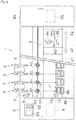
- the fine spinning machine 1 shown in Fig. 1 includes a blower box 80, a motor box 5, a plurality of spinning units 2 arranged side by side, and a yarn joining cart 3.
- a compressed air supply section 65 for supplying a compressed air to each of the spinning units 2 is provided inside the blower box 80.
- a blower (not shown) is arranged in the blower box 80. The blower supplies negative pressure to each of the spinning units 2.
- a common driving source (not shown) for each of the spinning units 2, a central control device 4, a display 51, and an operation unit 52 are arranged in the motor box 5.
- the central control device 4 intensively manages and controls each component of the fine spinning machine 1.
- the central control device 4 is configured as a known computer having a CPU, a ROM, and a RAM, etc. (not shown).
- the central control device 4 is connected to the unit control section 50 (see Fig. 2 ) provided in each of the spinning units 2 via a signal line (not shown).
- the display 51 can display settings for each of the spinning units 2, information on a state of each of the spinning units 2, and the like.
- An operator operates the operation unit 52, and thereby the type and/or addition amount of additive which will be described later, can be set.
- each of the spinning units 2 includes the unit control section 50, the predetermined number (two, four, or eight) of spinning units 2 may share the one unit control section 50.
- each of the spinning units 2 mainly includes a draft device 7, a spinning device 9, a yarn accumulation device 12, and a winding device 13, which are arranged in order from upstream to downstream.
- the terms "upstream” and “downstream” herein refer to upstream and downstream, in a traveling direction of a sliver 15, a fiber bundle 8, and a spun yarn 10, at a time of winding the spun yarn (yarn) 10.
- the draft device 7 is provided near an upper end of a frame 6 of the fine spinning machine 1. As shown in Fig. 2 , the draft device 7 has four pairs of draft rollers, which are a pair of back rollers 16, a pair of third rollers 17, a pair of middle rollers 19, and a pair of front rollers 20, in order from the upstream side. An apron belt 18 is provided with respect to each roller in the pair of middle rollers 19.
- the draft device 7 transports the sliver 15 that is supplied from a sliver case (not shown) while sandwiching the sliver 15 between the rollers included in the pair of draft rollers. Thereby, the sliver 15 is stretched (drafted) to a predetermined fiber amount (or thickness) and the fiber bundle 8 is formed.
- the fiber bundle 8 formed by the draft device 7 is supplied to the spinning device 9.
- the spinning device (air spinning device) 9 includes a fiber guide section (not shown), a spinning chamber, a swirling airflow current generation nozzle, and a hollow guide shaft.
- the fiber guide section guides the fiber bundle 8 supplied from the draft device 7 into the spinning chamber.
- the swirling airflow current generation nozzle is arranged around a path on which the fiber bundle 8 travels.
- the swirling airflow current generation nozzle generates a swirling airflow current inside the spinning chamber by injecting the compressed air. Such swirling airflow current causes each fiber end of the plurality of fibers that constitute the fiber bundle 8 to be inverted and swirled.
- the hollow guide shaft guides the formed spun yarn (yarn) 10 from the inside of the spinning chamber to the outside of the spinning device 9.
- the spinning device 9 forms the spun yarn 10 by applying twists to the fiber bundle 8 that is supplied from the draft device 7 by using the swirling airflow current that is generated by injecting the compressed air from a spinning nozzle into the spinning chamber. Then, the spinning device 9 supplies the spun yarn 10 to the devices in a downstream side.
- the yarn accumulation device 12 is provided downstream of the spinning device 9. As shown in Fig. 2 , the yarn accumulation device 12 includes the yarn accumulation roller 14, and a motor 25 for rotationally driving the yarn accumulation roller 14.
- the yarn accumulation roller 14 temporarily accumulates the spun yarn 10 by winding a certain amount of the spun yarn 10 on an outer peripheral surface thereof.
- the yarn accumulating roller 14 pulls the spun yarn 10 from the spinning device 9 and transports the spun yarn 10 to the downstream side at a predetermined speed by being rotated at a predetermined rotational speed with the spun yarn 10 wound on the outer peripheral surface thereof.
- the yarn accumulating device 12 can temporarily accumulate the spun yarn 10 on the outer peripheral surface of the yarn accumulating roller 14, the yarn accumulating device 12 can function as a kind of buffer of the spun yarn 10.
- the buffering function of the yarn accumulating device 12 avoids troubles (for example, slackening and the like of the spun yarn 10) caused by a mismatch in a spinning speed of the spinning device 9 and a winding speed (a traveling speed of the spun yarn 10 being wound into a package 45 which will be described later) due to some reason.
- a yarn monitoring device 59 is provided between the spinning device 9 and the yarn accumulation device 12.
- the spun yarn 10 that is formed in the spinning device 9 passes through the yarn monitoring device 59 before being wound by the yarn accumulation device 12.
- the yarn monitoring device 59 monitors the quality (thickness and the like) of the traveling spun yarn 10 by using a light transmission sensor, and detects a yarn defect included in the spun yarn 10 (portions having the abnormality in the thickness and the like of the spun yarn 10, and/or foreign matters etc.).
- the yarn monitoring device 59 transmits a yarn defect detection signal to the unit control section 50 when the yarn defect of the spun yarn 10 is detected.
- the yarn monitoring device 59 may monitor the quality of the spun yarn 10 by using a light reflective sensor or capacitance sensor, for example, not limited to the light transmission sensor.
- the unit control section 50 controls to cut the spun yarn 10 by controlling to stop drive of the spinning device 9 and/or the draft device 7, upon receipt of the yarn defect detection signal from the yarn monitoring device 59. That is, the spinning device 9 has the function as a cutting section for cutting the spun yarn 10 when the yarn monitoring device 59 detects the yarn defect.
- the spun yarn 10 may be cut by using a cutter.
- the winding device 13 includes a cradle arm 71, a winding drum 72, and a traverse guide 76.
- the cradle arm 71 is swingably supported around a supporting shaft 73.
- the cradle arm 71 can rotatably support a bobbin 48 (that is, the package 45) for winding the spun yarn 10.
- the winding drum 72 is rotated in contact with the outer peripheral surface of the bobbin 48 or the package 45, and thereby the package 45 is rotationally driven in a winding direction.
- the winding device 13 drives the winding drum 72 by an electric motor (not shown) while causing the traverse guide 76 to reciprocatingly move by using a driving member (not shown). As a result, the spun yarn 10 is wound into the package 45 while being traversed.
- a rail 41 is provided in the frame 6 of the spinning machine 1 along the direction in which the spinning units 2 are arranged side by side.
- the yarn joining cart 3 that is configured to travel on the rail 41 performs a yarn joining work with respect to the spinning unit 2 in which the yarn breakage has occurred.
- the yarn joining cart 3 includes a traveling wheel 42, a yarn joining device 43, a yarn catching section (a suction pipe 44 and a suction mouth 46), and a cart control section 70.
- the suction pipe 44 generates a suction air stream at its tip, which can suck and catch the spun yarn 10 from the spinning device 9.
- the suction mouth 46 generates a suction air stream at its tip, which can suck and catch the spun yarn 10 from the package 45 that is supported by the winding device 13.
- the suction pipe 44 and the suction mouth 46 are swung with the caught spun yarn 10, and thereby guide the spun yarn 10 to a position where the spun yarn 10 can be introduced to the yarn joining device 43.
- the yarn joining device 43 joins the spun yarn 10 from the spinning device 9 that is guided by the suction pipe 44 and the spun yarn 10 from the package 45 that is guided by the suction mouth 46.
- the yarn joining device 43 is a splicer device in which the yarn ends are twisted by using the swirling airflow current.
- the yarn joining device 43 is not limited to the above-described splicer device. For example, a mechanical knotter etc. may be adapted.
- the cart control section 70 is configured as a known computer having a CPU, a ROM, and a RAM, etc. (not shown).
- the cart control section 70 controls the operation of each component included in the yarn joining cart 3, and thereby controls the yarn joining work performed by the yarn joining cart 3.
- the fine spinning machine 1 further includes a compressed air supply device 60 and an additive supply device (additive supply section) 90.
- the compressed air supply device 60 includes a first main pipe (compressed air supply pipe) 61, a second main pipe 62, a first branch pipe 63 and a second branch pipe 64 for the number of spinning units, and a compressed air supply section 65 .
- the compressed air supply section 65 is arranged in a frame end portion, for example.
- the compressed air supply section 65 is constituted by a regulator, for example.
- the compressed air supply section 65 adjusts the pressure of the air pumped by an air pumping device 66 and supplies the compressed air after a pressure adjustment to the first main pipe 61 and the second main pipe 62.
- the air pumping device 66 is constituted by an electric compressor, for example.
- the air pumping device 66 is installed in a factory in which the fine spinning machine 1 is operated.
- the first main pipe 61 and the second main pipe 62 are arranged so as to extend in parallel or substantially in parallel with the direction in which the plurality of spinning units 2 is arranged side by side.
- the first main pipe 61 and the second main pipe 62 are commonly provided for each of the spinning units 2, and guide the compressed air supplied from the compressed air supply section 65 to each of the spinning units 2.
- a first main valve 81 is provided in an end portion in the upstream side of the first main pipe 61, and a second main valve 82 is provided in an end portion in the upstream side of the second main pipe 62.
- the first main valve 81 is located upstream of the first branch pipe 63 that is branched from the first main pipe 61 to each of the spinning units 2.
- the second main valve 82 is located upstream of the second branch pipe 64 that is branched from the second main pipe 62 to each of the spinning units 2.
- the central control device 4 controls opening and closing of the first main valve 81 and the second main valve 82. The operator may manually perform opening and closing of the first main valve 81 and the second main valve 82, not limited to a control by the central control device 4.
- the central control device 4 controls opening and closing of the first main valve 81 and the second main valve 82, which can switch supply/supply stop of the compressed air with respect to each of the spinning units 2 via the first main pipe 61 and the second main pipe 62. Either one of the first main valve 81 and the second main valve 82 is selected and then closed, which can switch the path through which the compressed air that is supplied from the compressed air supply section 65 flows.
- the misty additive is supplied from the additive supply device 90, at a position between the first main valve 81 and the first branch pipe 63 branched toward the spinning unit 2 that is located in the most upstream side in the direction to which the compressed air flows. That is, the compressed air that is distributed and supplied to each of the spinning units 2 via the first main pipe 61 is mixed with the misty additive.
- the additive is not supplied from the additive supply device 90 to the second main pipe 62.
- the compressed air including the misty additive may be referred to as a wet air.
- the compressed air (the air without the additive) that is supplied to each of the spinning units 2 via the second main pipe 62 may be referred to as a dry air.
- the central control device 4 controls opening and closing of the first main valve 81 and the second main valve 82, and thereby the compressed air that is supplied to the spinning device 9 of each of the spinning units 2 can be switched between the wet air and the dry air.
- a chemical agent for preventing accumulation of the oil in the spinning device 9, or water, etc. can be used as the additive to be supplied to the first main pipe 61.
- the chemical agent capable of applying at least one function such as antibacterial action, deodorization, odor-resistant, wax, etc. to the spun yarn 10 can be selected.
- the first branch pipe 63 is provided for each of the spinning units 2 one by one. One end of each first branch pipe 63 is connected to the first main pipe 61, and the other end is connected to the spinning device 9 of each of the spinning units 2. The first branch pipe 63 guides the wet air flowing through the first main pipe 61 to the spinning device 9 of each of the spinning units 2.
- a first supply valve 83 is provided in the first branch pipe 63.
- the first supply valve 83 is constituted by a control valve, for example.
- the first supply valve 83 is controlled by the unit control section 50.
- the unit control section 50 controls opening and closing of the first supply valve 83, which can switch supply/supply stop of the wet air with respect to the spinning device 9.
- the second branch pipe 64 is provided for each of the spinning units 2 one by one. One end of each second branch pipe 64 is connected to the second main pipe 62, and the other end is connected to the spinning device 9 of each of the spinning units 2. The second branch pipe 64 guides the dry air flowing through the second main pipe 62 to the spinning device 9 of each of the spinning units 2.
- a second supply valve 84 is provided in the second branch pipe 64.
- the second supply valve 84 is constituted by the control valve, for example.
- the second supply valve 84 is controlled by the unit control section 50.
- the unit control section 50 controls opening and closing of the second supply valve 84, which can switch supply/supply stop of the dry air with respect to the spinning device 9.
- the operator operates the operation unit 52, which can switch the compressed air supplied to the spinning device 9, either one of the wet air or the dry air.
- the additive supply device 90 functions as a supply source of the additive that is supplied to the fiber bundle 8.
- the additive supply device 90 includes a compressed air inlet tube 91, a pressure adjusting device 92, an additive accumulation tank 93, and an additive supply pipe 94.
- the compressed air inlet tube 91 guides the compressed air flowing through the first main pipe 61 guides to the additive accumulation tank 93.
- One end of the compressed air inlet tube 91 is connected to the first main pipe 61 in a downstream side of the first main valve 81, and the other end is connected to a mist generating nozzle 95 that is provided inside the additive accumulation tank 93.
- the mist generating nozzle 95 is arranged in the liquid additive that is accumulated in the additive accumulation tank 93.
- the mist generating nozzle 95 generates the misty additive (hereinafter, may be referred to as an additive mist) by bubbling the compressed air in the liquid additive.
- the pressure adjusting device 92 adjusts the pressure inside the additive accumulation tank 93 by adjusting the pressure of the compressed air to be introduced into the additive accumulation tank 93.
- the pressure adjusting device 92 can be constituted by a booster regulator and/or an electric compressor, for example.
- the pressure adjusting device 92 is controlled by the central control device 4.
- a booster ratio of the booster regulator may be automatically controlled by the central control device 4 or may be manually switched.
- the additive accumulation tank 93 is a pressure vessel for accumulating the additive.
- the additive accumulation tank 93 includes an accumulation amount detection section 93a for detecting an accumulated amount of additive.
- the liquid additive is accumulated inside the additive accumulation tank 93. Due to the above-described bubbling, the additive mist is filled in the air above a liquid level of the additive inside the additive accumulation tank 93.
- the pressure inside the additive accumulation tank 93 is adjusted higher than the pressure inside the first main pipe 61, and thereby the air including the additive mist is pumped into the first main pipe 61 via the additive supply pipe 94.
- the additive supply pipe 94 guides the additive mist inside the additive accumulation tank 93 to the first main pipe 61.
- One end of the additive supply pipe 94 is inserted into an upper space of the additive accumulation tank 93, and the other end is connected to the first main pipe 61.
- the additive supply pipe 94 is connected to the first main pipe 61.
- a portion where the additive supply pipe 94 is connected to the first main pipe 61 is located downstream of the portion where the compressed air inlet tube 91 is connected to the first main pipe 61, in a direction to which the compressed air flows. This can prevent the additive mist that is supplied into the first main pipe 61 via the additive supply pipe 94 from returning into the additive accumulation tank 93 via the compressed air inlet tube 91.
- a portion where the additive supply pipe 94 is connected to the first main pipe 61 is located upstream of the portion where the first branch pipe 63 that is located in the most upstream side is connected to the first main pipe 61. Accordingly, the additive mist can be distributed and supplied with respect to the first branch pipe 63 in each of the spinning units 2.
- a check valve 96 is preferably provided in the additive supply pipe 94. Accordingly, for example, when the pressure adjusting device 92 has stopped, a backflow of the compressed air that is caused by a pressure drop in the additive accumulation tank 93 can be prevented.
- the additive mist that is supplied into the first main pipe 61 is supplied to the spinning device 9 of each of the spinning units 2 via the first branch pipe 63, together with the compressed air flowing through the first main pipe 61.
- a part of the first main pipe 61 and the first branch pipe 63 are included in an additive supply path for supplying the additive from the additive supply device 90 to the spinning device 9 of each of the spinning units 2.
- a part of the first main pipe 61 (specifically, a portion on the downstream side where the additive supply pipe 94 is connected to the first main pipe 61) is a common portion (a common supply section 86) in the plurality of spinning units 2 of the additive supply path.
- Each of the plurality of first branch pipes 63 that is branched from the common supply section 86 is a branch supply section in the additive supply path.
- a part of a path for supplying the compressed air to the spinning device 9 is used as the additive supply path, and thereby it is unnecessary that the additive supply path is separately provided. This can simplify a configuration of the fine spinning machine 1.
- the central control device 4 adjusts the pressure inside the additive accumulation tank 93 by controlling the pressure adjusting device 92. Accordingly, the amount of additive to be supplied to the first main pipe 61 can be controlled.
- the type and addition amount of additive to be used for spinning is appropriately determined in consideration of needs, etc. required for the yarn.
- the operator appropriately operates the operation unit 52, and thereby the type and addition amount of additive can be set in the central control device 4.
- the central control device 4 may automatically set the addition amount of additive depending on materials of the sliver 15 to be spun.
- the operator manually operates the pressure adjusting device 92 (including a case of switching the booster regulator), the addition amount of additive may be changed.
- the operator may change the type of additive to be accumulated in the additive accumulation tank 93 depending on the materials of the sliver 15 to be spun.
- the central control device 4 includes a storage section 40.
- the storage section 40 stores various setting data relating to a preset additive.
- Such setting data is, for example, the type of additive that is set in association with the materials of the sliver 15, a setting addition amount that is set in association with the type of additive, a setting temperature that is set in association with the type of additive, and the like.
- the setting temperature may be set in association with the type and addition amount of additive.
- the central control device 4 recognizes the setting addition amount that is stored in the storage section 40 as a target addition amount, based on the information inputted by the operator via the operation unit 52 (based on the type of materials of the sliver 15 and/or the type of additive, etc.), and controls the pressure of the compressed air that is supplied by the pressure adjusting device 92.
- an addition amount detection section 97 is provided in the fine spinning machine 1 of this embodiment.
- the addition amount detection section 97 is constituted by an optical sensor, for example.
- the addition amount detection section 97 is arranged in the first main pipe 61.
- a position where the addition amount detection section 97 is arranged in the first main pipe 61 is located downstream of a portion where the additive supply pipe 94 is connected to the first main pipe 61, and located upstream of the portion where the first branch pipe 63 in the most upstream side is connected to the first main pipe 61.
- a transparent section 98 is arranged in a part of the first main pipe 61, and the addition amount detection section 97 is mounted to the outside of the transparent section 98.
- the addition amount detection section 97 may be provided inside the first main pipe 61.
- a detection result of the addition amount detection section 97 is transmitted to the central control device 4.
- the central control device 4 transmits an operation stop command to the unit control section 50 and controls to stop a spinning operation in a part of or all of the spinning units 2. This can prevent deterioration in the yarn quality caused by spinning in a state where the addition amount of additive is excessive or insufficient.
- the fine spinning machine 1 of this embodiment further includes an additive heating section (heating section) 21 and an additive temperature detection section (temperature detection section) 22.
- the additive heating section 21 and the additive temperature detection section 22 are arranged in the additive supply device 90.
- the central control device 4 controls the operation of the additive heating section 21 based on the additive temperature that is detected in the additive temperature detection section 22 during the operation of each of the spinning units 2 (that is, during spinning).
- the additive heating section 21 is constituted by a heating device with a heating function. As shown in Fig. 3 , the additive heating section 21 is mounted to a wall surface of the additive accumulation tank 93, for example. The additive heating section 21 is preferably mounted on an outer wall surface of the additive accumulation tank 93, and mounted near a position where the mist generating nozzle 95 is arranged. This can easily adjust the temperature of the additive mist generated by bubbling.
- the additive heating section 21 may be provided near the additive accumulation tank 93 or inside the additive accumulation tank 93, for example. In this embodiment, although the additive heating section 21 has both functions of heating and cooling, the cooling function may be omitted.
- the additive temperature detection section 22 is constituted by a temperature sensor, for example.
- the additive temperature detection section 22 of this embodiment is mounted to the outer wall surface of the additive accumulation tank 93.
- the additive temperature detection section 22 detects the temperature of a wall portion of the additive accumulation tank 93, and thereby detects the temperature of the additive that is accumulated inside the additive accumulation tank 93, but this is not limited thereto.
- the additive temperature detection section 22 may be provided inside the additive accumulation tank 93.
- a stirring device (not shown) is provided inside the additive accumulation tank 93. Accordingly, the additive can be evenly heated, and thereby fluctuate of the additive temperature inside the additive accumulation tank 93 can be prevented. Therefore, even when the additive temperature detection section 22 is mounted to the outer wall surface of the additive accumulation tank 93, the temperature of the additive that is accumulated inside the additive accumulation tank 93 can be accurately detected.
- the central control device 4 sets a setting temperature that is set in the storage section 40 as a target temperature of the additive heating section 21 based on the type and addition amount of additive that is supplied to each of the spinning units 2, and controls the operation of the additive heating section 21. For example, when the temperature in an installation environment of the fine spinning machine 1 is higher than the target temperature, the additive heating section 21 cools the additive under control of the central control device 4. On the contrary, when the temperature in the installation environment of the fine spinning machine 1 is lower than the target temperature, the additive heating section 21 heats the additive under control of the central control device 4. Accordingly, the additive temperature can be maintained so as to effectively exert detergency.
- the target temperature can be set to an appropriate temperature 20 °C or more and 60° C or less.
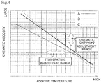
- Fig. 4 is a graph showing a relationship between the temperature and the kinetic viscosity in three types of additives A, B, and C.
- the central control device 4 controls so that the additive temperature is within a temperature range indicated by an outline arrow in the horizontal direction. With this control, the kinetic viscosity of the additive can be maintained within a range indicated by the outline arrow in the vertical direction.
- the kinetic viscosity of the additive is appropriately maintained, which can maintain sprayability and can keep a spray amount (addition amount) of the additive constant. Therefore, fluctuate of the addition amount of additive caused by a change in the kinetic viscosity of the additive can be prevented, and the quality of the spun yarn 10 to be spun can be satisfactorily maintained.
- the range of the kinetic viscosity of the additive is preferably 5 ⁇ 10 -6 or more and 50 ⁇ 10 -6 or less, for example.
- the additive temperature is maintained within a relatively high range, and thereby a low surface tension of the additive can be maintained. This can improve wettability on a contaminated surface, easily permeate the additive such as a cleaning solution, and expect improvement in detergency.
- the central control device 4 In the start of the fine spinning machine 1, when the additive temperature does not reach the predetermined temperature, the central control device 4 does not controls to start operation (spinning) in each of the spinning units 2 and controls that the additive heating section 21 heats the additive.
- the fine spinning machine 1 is powered on and the operator performs a predetermined operation, and then the fine spinning machine 1 is started.
- the central control device 4 immediately starts a temperature control of the additive by the additive heating section 21 and the additive temperature detection section 22. After that, the central control device 4 waits until a predetermined condition (hereinafter, referred to as a spinning start condition) for causing each of the spinning units 2 to start forming the spun yarn 10 is met while continuing the temperature control of the additive.
- a spinning start condition for causing each of the spinning units 2 to start forming the spun yarn 10 is met while continuing the temperature control of the additive.
- the central control device 4 transmits a spinning start enable signal to the unit control section 50 of each of the spinning units 2 and controls to start spinning in each of the spinning units 2.
- the spinning start condition includes a condition that the additive temperature reaches the predetermined temperature near the above-described target temperature. This can prevent forming of the spun yarn 10 with a low quality.
- the spinning start condition may include various conditions that, for example, a warm-up operation of the above-described blower has completed (specifically, a static pressure of the blower is equal to or higher than the predetermined value).
- the central control device 4 monitors the additive temperature that is detected by the additive temperature detection section 22. Accordingly, the central control device 4 determines whether or not the abnormality has occurred in the additive temperature. For example, a malfunction of the additive heating section 21 may cause the abnormality in the temperature.
- the central control device 4 determines that the abnormality has occurred in the additive temperature and transmits an operation stop command to the unit control section 50. As a result, spinning in a part of or all of the spinning units 2 is stopped. As such, when the abnormality has occurred in the additive temperature, spinning can be automatically stopped. Therefore, deterioration in the yarn quality can be prevented.
- the fine spinning machine 1 of this embodiment includes the plurality of spinning units 2, the additive supply device 90, the additive supply path, the additive heating section 21, the additive temperature detection section 22, and the central control device 4.
- Each of the spinning units 2 having at least the draft device 7 and the spinning device 9 forms and winds the spun yarn 10.
- the additive supply device 90 is an additive supply source for supplying the additive.
- the additive supply path guides the additive from the additive supply device 90 to the spinning device 9 in each of the spinning units 2.
- the additive heating section 21 that is provided in the additive supply device 90 heats the additive.
- the additive temperature detection section 22 that is provided in the additive supply device 90 detects the additive temperature.
- the central control device 4 controls the operation of the additive heating section 21 based on the detection result of the additive temperature detection section 22.
- the additive temperature can be appropriately maintained, an effect of which the additive suppresses the accumulation of oil can be stabilized. Therefore, the yarn quality can be satisfactorily maintained.
- the fine spinning machine 1 of this embodiment includes the storage section 40.
- the storage section 40 stores the setting addition amount that is preset depending on the type of additive.
- the central control device 4 sets the setting addition amount that is obtained from the storage section 40 as the target addition amount of the additive to be supplied to the spinning device 9, based on the type of additive.
- the addition amount can be appropriately and automatically set based on the type of set additive or detected additive.
- the fine spinning machine 1 of this embodiment includes the storage section 40.
- the storage section 40 stores the setting temperature that is preset depending on the type of additive.
- the central control device 4 sets the setting temperature that is obtained from the storage section 40 as the target temperature of the additive heating section 21, based on the type of additive.
- the target temperature with respect to the additive can be appropriately and automatically set.
- the fine spinning machine 1 of this embodiment includes the storage section 40.
- the storage section 40 stores the setting temperature that is preset depending on the type and addition amount of additive.
- the central control device 4 sets the setting temperature that is obtained from the storage section 40 as the target temperature of the additive heating section 21, based on the type and addition amount of additive.
- the target temperature with respect to the additive can be further appropriately set by considering the addition amount of additive.
- the additive supply device 90 includes the additive accumulation tank 93 for accumulating the additive.
- the additive supply device 90 is commonly provided for the plurality of spinning units 2.
- the additive heating section 21 is provided in the additive accumulation tank 93.
- heating with respect to the additive to be supplied to the plurality of spinning units 2 can be achieved with a simple configuration.
- the additive temperature detection section 22 that is provided in the additive accumulation tank 93 detects the temperature of the additive inside the additive accumulation tank 93.
- the temperature of the additive to be supplied to the plurality of spinning units 2 can be recognized with a simple configuration.
- the central control device 4 controls to stop forming the spun yarn 10 in a part of or all of the spinning units 2.
- forming of the spun yarn 10 can be automatically stopped when the abnormality has occurred in the additive temperature. Therefore, deterioration in the yarn quality can be prevented.
- the additive supply path includes the common supply section 86 and the first branch pipe 63.
- the common supply section 86 is commonly provided for the plurality of spinning units 2.
- the first branch pipe 63 is branched from the common supply section 86 to each of the spinning units 2.
- the additive from the additive supply device 90 is supplied to the common supply section 86 that is located upstream of each first branch pipe 63 in each of the spinning units 2, in an additive flowing direction.
- the fine spinning machine 1 of this embodiment includes the first main pipe 61.
- the first main pipe 61 supplies the compressed air to each of the spinning units 2.
- a part of the first main pipe 61 is included in the additive supply path.
- the additive supply device 90 changes the liquid additive to a misty additive and then supplies to the first main pipe 61.
- the existing pipe can constitute the additive supply path, and thereby a configuration of the fine spinning machine 1 can be simplified.
- the spinning device 9 is an air spinning device adapted to form the spun yarn 10 by applying twists to the fiber bundle 8 by using the swirling airflow current.
- the first main pipe 61 supplies the compressed air for generating the swirling airflow current in the spinning device 9.
- the additive can be supplied into the spinning device 9 by utilizing the existing configuration, and thereby the configuration of the fine spinning machine 1 can be simplified.
- the fine spinning machine 1 of this embodiment includes the addition amount detection section 97 for detecting the addition amount of additive which flows through the additive supply path.
- the addition amount of additive to be supplied to each of the spinning units 2 can be more accurately controlled.
- the addition amount detection section 97 is constituted by the optical sensor.
- the addition amount detection section 97 with high precision can be easily configured.
- the central control device 4 controls to stop forming the spun yarn 10 in a part of or all of the spinning units 2.
- a condition that the central control device 4 controls to start forming the spun yarn 10 in each of the spinning units 2 after start of the fine spinning machine 1 includes the condition that the additive temperature that is detected by the additive temperature detection section 22 reaches the predetermined temperature.
- formation of the spun yarn 10 is not started when the additive temperature does not reach the predetermined temperature. This can prevent formation of the spun yarn 10 with low quality.
- the additive supply device 90 may be provided for each of the spinning units 2, or may be commonly provided for the plurality of spinning units 2 (but not all of the spinning units 2). In this case, when the additive temperature that is detected by the additive temperature detection section 22 is out of the predetermined range, the central control device 4 controls to stop spinning in the one spinning unit 2 (or the plurality of spinning units 2) corresponding to the additive temperature detection section 22.
- the additive supply device 90 may be covered with a heat-insulating member. Accordingly, energy saving can be achieved.
- the additive supply device 90 may have an overheat prevention device for preventing an excess temperature rise in the additive.
- the temperature of the misty additive may be indirectly adjusted by adjusting the temperature of the compressed air as a carrier of the misty additive.
- a heating and cooling device having a function to heat and cool the compressed air is provided in the first main pipe 61.
- Such heating and cooling device can be installed on the upstream side of a position where the first branch pipe 63 in the most upstream side is connected to the first main pipe 61, in the direction to which the wet air flows, for example.
- the heating and cooling device is also a kind of additive heating section.
- At least one heating section may be provided in the middle of the first main pipe 61 commonly provided for the plurality of spinning units 2.
- the additive temperature detection section 22 may be provided in the additive supply pipe 94, etc.
- the additive temperature detection section 22 is preferably provided between the additive accumulation tank 93 and the check valve 96, in view of a detection accuracy of the additive temperature.
- the additive temperature detection section 22 may be mounted to a portion corresponding to the spinning unit 2 located in the most downstream side, in the direction to which the wet air flows.
- the additive temperature detection section 22 may be mounted to the first branch pipe 63.
- the wet air/dry air may be supplied to each of the spinning units 2 by controlling the operation of the additive supply device 90 and switching supply/supply stop of the additive to the first main pipe 61.
- the second main pipe 62 can be omitted.
- Each downstream portion of the first branch pipe 63 and the second branch pipe 64 may be merged and then connected to the spinning device 9.
- a switching valve is provided in such merged portion, and thereby supply/supply stop of the wet air and the dry air may be switched.
- the additive supply device 90 may mist the liquid additive to be accumulated, by using materials of venturi effect.
- the kinetic viscosity may be changed by adjusting the additive temperature, and then the addition amount may be adjusted by utilizing a change of spray amount depending on the kinetic viscosity.
- the yarn joining device may be provided in each of the spinning units 2.
- the spinning machine 1 is configured as an air jet spinning machine in which the spun yarn 10 travels from bottom to top, with respect to the machine frame of the fine spinning machine 1.
- an additive supply device including the additive accumulation tank 93 and the additive supply pipe may be used.
- an additive supply port is provided in an end portion of the additive supply pipe.
- the additive supply port is arranged near the spinning device 9, in the upstream side of the spinning device 9 in the direction to which the fiber bundle 8 flows, for example. Therefore, the additive is guided to between the draft device 7 and the spinning device 9.
- the additive supply device supplies the liquid additive to the fiber bundle 8 before (immediately before) being introduced into the spinning device 9 via the additive supply port.
- the liquid additive may be sprayed in mist to the fiber bundle 8, or may be applied to the fiber bundle 8 without misting.
- the additive supply pipe is provided separately from pipes (the first main pipe 61 and the second main pipe 62) for supplying the compressed air to each of the spinning units 2.
- the additive supply pipe connects the additive accumulation tank 93 and the additive supply port, and guides the additive from the additive accumulation tank 93 to the additive supply port.
- the first main pipe 61 for supplying the wet air can be omitted.
- the additive can be supplied to the fiber bundle 8 at an arbitrary position between an outlet of the draft device 7 and the outlet of the spinning device 9.
- the outlet of the draft device 7 means the most downstream side portion of the draft device 7 in the direction to which the fiber bundle 8 flows.
- the outlet of the draft device 7 is a portion near a nip point of the pair of front rollers 20.
- the outlet of the spinning device 9 means the most downstream portion of the spinning device 9.
- the central control device 4 controls the additive temperature, and controls spinning/spinning stop in each of the spinning units 2.
- spinning/spinning stop in each of the spinning units 2 may be controlled by a control device other than the central control device 4.
- the central control device 4 may be achieved with one computer, or may be achieved with a number of computers.
Landscapes
- Engineering & Computer Science (AREA)
- Mechanical Engineering (AREA)
- Textile Engineering (AREA)
- Chemical & Material Sciences (AREA)
- Oil, Petroleum & Natural Gas (AREA)
- Spinning Or Twisting Of Yarns (AREA)
Abstract
Description
- The present invention relates to an air spinning machine for spinning while supplying an additive.
- An air spinning machine adapted to supply an additive to a spinning device has been conventionally known. The additive is used for preventing oil applied to raw materials from adhering and accumulating inside the spinning device in a case of spinning by using the raw materials such as polyester.
- Patent Document 1 (Japanese Patent Application Laid-Open No.
2017-150123 - The air spinning machine in
Patent Document 1 is configured to supply a certain amount of additive to each spinning unit per unit time via a supply device that is arranged in the vicinity of an inlet of a spinning nozzle of each of the spinning units. - A cleaning effect of an additive changes depending on the temperature. Therefore, the air spinning machine in
Patent Document 1 tends to have fluctuate in an effect of which the additive suppresses accumulation of oil depending on an installation environment of the air spinning machine. This leaves room for improvement from the viewpoint of stabilizing a yarn quality. - The present invention has been made in view of the circumstances described above, and an object of the present invention is to provide an air spinning machine capable of avoiding degradation in a yarn quality due to an installation environment of the air spinning machine.
- Problems to be solved by the present invention are as described above, and next, means for solving the problems and effects thereof will be described.
- According to an aspect of the present invention, an air spinning machine with the following configuration is provided. That is, the air spinning machine includes a plurality of spinning units, at least one additive supply section, an additive supply path, a heating section, a temperature detection section, and a control section. Each of the spinning units includes at least a draft device and a spinning device. Each of the spinning units forms and winds a yarn. The additive supply section is an additive supply source for supplying an additive. The additive supply path guides the additive from the additive supply section to between the draft device and the spinning device in each of the spinning units or guides to the spinning device in each of the spinning units. The heating section that is provided in the additive supply section heats the additive. The temperature detection section that is provided in the additive supply section detects the additive temperature. The control section controls an operation of the heating section based on a detection result of the temperature detection section.
- Accordingly, the additive temperature can be appropriately maintained, and thereby an effect of the additive can be stabilized. Therefore, a yarn quality can be satisfactorily maintained.
- The air spinning machine is preferably configured as follows. That is, the air spinning machine includes a storage section. The storage section stores a setting addition amount that is preset depending on the type of additive. The control section sets the setting addition amount that is obtained from the storage section as a target addition amount of additive to be supplied to between the draft device and the spinning device or to be supplied to the spinning device, based on the type of additive.
- Accordingly, an addition amount can be appropriately and automatically set based on the set or detected additive type.
- The air spinning machine is preferably configured as follows. That is, the air spinning machine includes a storage section. The storage section stores a setting temperature that is preset depending on the type of additive. The control section sets the setting temperature that is obtained from the storage section as a target temperature of the heating section, based on the type of additive.
- Accordingly, the target temperature with respect to the additive can be appropriately and automatically set.
- The air spinning machine is preferably configured as follows. That is, the air spinning machine includes a storage section. The storage section stores a setting temperature that is preset depending on the type of additive and the addition amount. The control section sets the setting temperature that is obtained from the storage section as a target temperature of the heating section, based on the type of additive and the addition amount.
- Accordingly, the target temperature with respect to the additive can be more appropriately set by considering the addition amount of additive.
- The air spinning machine is preferably configured as follows. That is, the additive supply section includes an additive accumulation tank for accumulating the additive. The additive accumulation tank is commonly provided for the plurality of spinning units. The heating section is provided in the additive accumulation tank.
- Accordingly, heating for the additive to be supplied to the plurality of spinning units can be achieved with a simple configuration.
- In the air spinning machine, it is preferable that the temperature detection section that is provided in the additive accumulation tank detects the temperature of the additive inside the additive accumulation tank.
- Accordingly, the temperature of the additive to be supplied to the plurality of spinning units can be recognized with a simple configuration.
- In the air spinning machine, when the additive temperature that is detected by the temperature detection section is out of a predetermined range, the control section preferably controls to stop forming the yarn in a part of or all of the spinning units.
- Accordingly, formation of the yarn can be automatically stopped when an abnormality has occurred in the additive temperature. Therefore, deterioration in the yarn quality can be prevented.
- The air spinning machine is preferably configured as follows. That is, the additive supply path includes a common supply section and a branch supply section. The common supply section is commonly provided for the plurality of spinning units. The branch supply section is branched from the common supply section to each of the spinning units. The additive from the additive supply section is supplied to the common supply section on an upstream side of the branch supply section in each of the spinning units, in an additive flowing direction.
- Accordingly, a configuration of which the additive is supplied to the plurality of spinning units can be simplified.
- The air spinning machine is preferably configured as follows. That is, the air spinning machine includes a compressed air supply pipe. The compressed air supply pipe supplies a compressed air to each of the spinning units. At least a part of the compressed air supply pipe is included in the additive supply path. The additive supply section changes a liquid additive to a misty additive, and supplies the misty additive to the compressed air supply pipe.
- Accordingly, the additive supply path can be formed by the existing pipe, and the configuration of the air spinning machine can be simplified.
- The air spinning machine is preferably configured as follows. That is, the spinning device is an air spinning device adapted to form a yarn by applying twists to a fiber bundle by using a swirling airflow current. The compressed air supply pipe supplies the compressed air for generating the swirling airflow current in the air spinning device.
- Accordingly, the additive can be supplied into the air spinning device by using the existing configuration, and the configuration of the air spinning machine can be simplified.
- The air spinning machine can be also configured as follows. That is, the additive supply section includes an additive accumulation tank for accumulating the additive. The additive accumulation tank is provided in each of the plurality of spinning units. The temperature detection section that is provided in the additive accumulation tank detects the temperature of the additive inside the additive accumulation tank.
- Accordingly, the temperature of the additive accumulated in the additive accumulation tank that is provided in each of the spinning units can be recognized with a simple configuration.
- In the air spinning machine, when the additive temperature that is detected by the temperature detection section is out of a predetermined range, the control section preferably controls to stop forming the yarn in the spinning unit having the temperature detection section.
- Accordingly, formation of the yarn can be automatically stopped when the abnormality has occurred in the additive temperature. Therefore, deterioration in the yarn quality can be prevented.
- The air spinning machine preferably includes an addition amount detection section adapted to detect the addition amount of additive flowing through the additive supply path.
- Accordingly, the addition amount of additive that is supplied to each of the spinning units can be further accurately controlled.
- In the air spinning machine, the addition amount detection section is preferably constituted by an optical sensor.
- Accordingly, the addition amount detection section with high precision can be easily configured.
- In the air spinning machine, when the difference between the addition amount that is detected by the addition amount detection section and the set target addition amount exceeds a predetermined value, the control section preferably controls to stop forming the yarn in a part of or all of the spinning units.
- Accordingly, when the abnormality has occurred in the addition amount of additive, formation of the yarn can be automatically stopped. Therefore, deterioration in the yarn quality can be prevented.
- The air spinning machine is preferably configured as follows. That is, the spinning device is an air spinning device adapted to form a yarn by applying twists to a fiber bundle by using a swirling airflow current. The additive supply section supplies the liquid additive to the fiber bundle via an additive supply port that is provided on the upstream side of the air spinning device in a direction to which the fiber bundle travels.
- Accordingly, the liquid additive can be supplied into the air spinning device via the fiber bundle.
- In the air spinning machine, the additive supply section preferably supplies the liquid additive to the fiber bundle via the additive supply port in mist or without mist.
- Accordingly, the additive can be appropriately added to the fiber bundle.
- In the air spinning machine, it is preferable that a condition that the control section controls to start forming the yarn in each of the spinning units after start of the air spinning machine includes the condition that the additive temperature that is detected by the temperature detection section reaches a predetermined temperature.
- Accordingly, formation of the yarn is not started when the additive temperature does not reach the predetermined temperature. This can prevent formation of the yarn with low quality.
-
-
Fig. 1 is a plan view showing an overall configuration of a fine spinning machine according to one embodiment of the present invention. -
Fig. 2 is a side view showing a spinning unit and a yarn joining cart. -
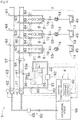
Fig. 3 is a configuration showing an air distribution device and an additive supply device. -
Fig. 4 is a graph showing a relationship between the kinetic viscosity and the temperature of an additive. - Next, a fine spinning machine (air spinning machine) 1 according to one embodiment of the present invention will be described with reference to drawings.
- The
fine spinning machine 1 shown inFig. 1 includes ablower box 80, amotor box 5, a plurality of spinningunits 2 arranged side by side, and ayarn joining cart 3. - A compressed
air supply section 65 for supplying a compressed air to each of thespinning units 2 is provided inside theblower box 80. A blower (not shown) is arranged in theblower box 80. The blower supplies negative pressure to each of thespinning units 2. - A common driving source (not shown) for each of the
spinning units 2, acentral control device 4, adisplay 51, and anoperation unit 52 are arranged in themotor box 5. - The
central control device 4 intensively manages and controls each component of thefine spinning machine 1. Thecentral control device 4 is configured as a known computer having a CPU, a ROM, and a RAM, etc. (not shown). Thecentral control device 4 is connected to the unit control section 50 (seeFig. 2 ) provided in each of thespinning units 2 via a signal line (not shown). Thedisplay 51 can display settings for each of thespinning units 2, information on a state of each of thespinning units 2, and the like. An operator operates theoperation unit 52, and thereby the type and/or addition amount of additive which will be described later, can be set. In this embodiment, although each of thespinning units 2 includes theunit control section 50, the predetermined number (two, four, or eight) of spinningunits 2 may share the oneunit control section 50. - As shown in
Fig. 1 , each of thespinning units 2 mainly includes adraft device 7, aspinning device 9, ayarn accumulation device 12, and a windingdevice 13, which are arranged in order from upstream to downstream. The terms "upstream" and "downstream" herein refer to upstream and downstream, in a traveling direction of asliver 15, afiber bundle 8, and a spunyarn 10, at a time of winding the spun yarn (yarn) 10. - The
draft device 7 is provided near an upper end of aframe 6 of thefine spinning machine 1. As shown inFig. 2 , thedraft device 7 has four pairs of draft rollers, which are a pair ofback rollers 16, a pair of third rollers 17, a pair of middle rollers 19, and a pair of front rollers 20, in order from the upstream side. An apron belt 18 is provided with respect to each roller in the pair of middle rollers 19. - The
draft device 7 transports thesliver 15 that is supplied from a sliver case (not shown) while sandwiching thesliver 15 between the rollers included in the pair of draft rollers. Thereby, thesliver 15 is stretched (drafted) to a predetermined fiber amount (or thickness) and thefiber bundle 8 is formed. Thefiber bundle 8 formed by thedraft device 7 is supplied to thespinning device 9. - The spinning device (air spinning device) 9 includes a fiber guide section (not shown), a spinning chamber, a swirling airflow current generation nozzle, and a hollow guide shaft. The fiber guide section guides the
fiber bundle 8 supplied from thedraft device 7 into the spinning chamber. The swirling airflow current generation nozzle is arranged around a path on which thefiber bundle 8 travels. The swirling airflow current generation nozzle generates a swirling airflow current inside the spinning chamber by injecting the compressed air. Such swirling airflow current causes each fiber end of the plurality of fibers that constitute thefiber bundle 8 to be inverted and swirled. The hollow guide shaft guides the formed spun yarn (yarn) 10 from the inside of the spinning chamber to the outside of thespinning device 9. As such, thespinning device 9 forms the spunyarn 10 by applying twists to thefiber bundle 8 that is supplied from thedraft device 7 by using the swirling airflow current that is generated by injecting the compressed air from a spinning nozzle into the spinning chamber. Then, thespinning device 9 supplies the spunyarn 10 to the devices in a downstream side. - The
yarn accumulation device 12 is provided downstream of thespinning device 9. As shown inFig. 2 , theyarn accumulation device 12 includes theyarn accumulation roller 14, and amotor 25 for rotationally driving theyarn accumulation roller 14. - The
yarn accumulation roller 14 temporarily accumulates the spunyarn 10 by winding a certain amount of the spunyarn 10 on an outer peripheral surface thereof. Theyarn accumulating roller 14 pulls the spunyarn 10 from thespinning device 9 and transports the spunyarn 10 to the downstream side at a predetermined speed by being rotated at a predetermined rotational speed with the spunyarn 10 wound on the outer peripheral surface thereof. - As such, since the
yarn accumulating device 12 can temporarily accumulate the spunyarn 10 on the outer peripheral surface of theyarn accumulating roller 14, theyarn accumulating device 12 can function as a kind of buffer of the spunyarn 10. The buffering function of theyarn accumulating device 12 avoids troubles (for example, slackening and the like of the spun yarn 10) caused by a mismatch in a spinning speed of thespinning device 9 and a winding speed (a traveling speed of the spunyarn 10 being wound into apackage 45 which will be described later) due to some reason. - A
yarn monitoring device 59 is provided between the spinningdevice 9 and theyarn accumulation device 12. The spunyarn 10 that is formed in thespinning device 9 passes through theyarn monitoring device 59 before being wound by theyarn accumulation device 12. - The
yarn monitoring device 59 monitors the quality (thickness and the like) of the traveling spunyarn 10 by using a light transmission sensor, and detects a yarn defect included in the spun yarn 10 (portions having the abnormality in the thickness and the like of the spunyarn 10, and/or foreign matters etc.). Theyarn monitoring device 59 transmits a yarn defect detection signal to theunit control section 50 when the yarn defect of the spunyarn 10 is detected. Theyarn monitoring device 59 may monitor the quality of the spunyarn 10 by using a light reflective sensor or capacitance sensor, for example, not limited to the light transmission sensor. - The
unit control section 50 controls to cut the spunyarn 10 by controlling to stop drive of thespinning device 9 and/or thedraft device 7, upon receipt of the yarn defect detection signal from theyarn monitoring device 59. That is, thespinning device 9 has the function as a cutting section for cutting the spunyarn 10 when theyarn monitoring device 59 detects the yarn defect. The spunyarn 10 may be cut by using a cutter. - The winding
device 13 includes acradle arm 71, a windingdrum 72, and atraverse guide 76. Thecradle arm 71 is swingably supported around a supportingshaft 73. Thecradle arm 71 can rotatably support a bobbin 48 (that is, the package 45) for winding the spunyarn 10. The windingdrum 72 is rotated in contact with the outer peripheral surface of thebobbin 48 or thepackage 45, and thereby thepackage 45 is rotationally driven in a winding direction. The windingdevice 13 drives the windingdrum 72 by an electric motor (not shown) while causing thetraverse guide 76 to reciprocatingly move by using a driving member (not shown). As a result, the spunyarn 10 is wound into thepackage 45 while being traversed. - As shown in
Fig. 1 , arail 41 is provided in theframe 6 of the spinningmachine 1 along the direction in which thespinning units 2 are arranged side by side. Theyarn joining cart 3 that is configured to travel on therail 41 performs a yarn joining work with respect to thespinning unit 2 in which the yarn breakage has occurred. - As shown in
Fig. 1 etc., theyarn joining cart 3 includes a travelingwheel 42, ayarn joining device 43, a yarn catching section (asuction pipe 44 and a suction mouth 46), and acart control section 70. - The
suction pipe 44 generates a suction air stream at its tip, which can suck and catch the spunyarn 10 from thespinning device 9. Thesuction mouth 46 generates a suction air stream at its tip, which can suck and catch the spunyarn 10 from thepackage 45 that is supported by the windingdevice 13. Thesuction pipe 44 and thesuction mouth 46 are swung with the caught spunyarn 10, and thereby guide the spunyarn 10 to a position where the spunyarn 10 can be introduced to theyarn joining device 43. - The
yarn joining device 43 joins the spunyarn 10 from thespinning device 9 that is guided by thesuction pipe 44 and the spunyarn 10 from thepackage 45 that is guided by thesuction mouth 46. In this embodiment, theyarn joining device 43 is a splicer device in which the yarn ends are twisted by using the swirling airflow current. Theyarn joining device 43 is not limited to the above-described splicer device. For example, a mechanical knotter etc. may be adapted. - The
cart control section 70 is configured as a known computer having a CPU, a ROM, and a RAM, etc. (not shown). Thecart control section 70 controls the operation of each component included in theyarn joining cart 3, and thereby controls the yarn joining work performed by theyarn joining cart 3. - Next, a configuration of which the compressed air and the additive are supplied to each of the
spinning units 2, in thefine spinning machine 1, will be detailedly described. - The
fine spinning machine 1 further includes a compressedair supply device 60 and an additive supply device (additive supply section) 90. The compressedair supply device 60 includes a first main pipe (compressed air supply pipe) 61, a secondmain pipe 62, afirst branch pipe 63 and asecond branch pipe 64 for the number of spinning units, and a compressedair supply section 65 . - The compressed
air supply section 65 is arranged in a frame end portion, for example. The compressedair supply section 65 is constituted by a regulator, for example. The compressedair supply section 65 adjusts the pressure of the air pumped by anair pumping device 66 and supplies the compressed air after a pressure adjustment to the firstmain pipe 61 and the secondmain pipe 62. Theair pumping device 66 is constituted by an electric compressor, for example. Theair pumping device 66 is installed in a factory in which thefine spinning machine 1 is operated. - The first
main pipe 61 and the secondmain pipe 62 are arranged so as to extend in parallel or substantially in parallel with the direction in which the plurality of spinningunits 2 is arranged side by side. The firstmain pipe 61 and the secondmain pipe 62 are commonly provided for each of thespinning units 2, and guide the compressed air supplied from the compressedair supply section 65 to each of thespinning units 2. - In the direction to which the compressed air flows, a first
main valve 81 is provided in an end portion in the upstream side of the firstmain pipe 61, and a secondmain valve 82 is provided in an end portion in the upstream side of the secondmain pipe 62. In the firstmain pipe 61, the firstmain valve 81 is located upstream of thefirst branch pipe 63 that is branched from the firstmain pipe 61 to each of thespinning units 2. In the secondmain pipe 62, the secondmain valve 82 is located upstream of thesecond branch pipe 64 that is branched from the secondmain pipe 62 to each of thespinning units 2. Thecentral control device 4 controls opening and closing of the firstmain valve 81 and the secondmain valve 82. The operator may manually perform opening and closing of the firstmain valve 81 and the secondmain valve 82, not limited to a control by thecentral control device 4. - The
central control device 4 controls opening and closing of the firstmain valve 81 and the secondmain valve 82, which can switch supply/supply stop of the compressed air with respect to each of thespinning units 2 via the firstmain pipe 61 and the secondmain pipe 62. Either one of the firstmain valve 81 and the secondmain valve 82 is selected and then closed, which can switch the path through which the compressed air that is supplied from the compressedair supply section 65 flows. - In the first
main pipe 61, the misty additive is supplied from theadditive supply device 90, at a position between the firstmain valve 81 and thefirst branch pipe 63 branched toward thespinning unit 2 that is located in the most upstream side in the direction to which the compressed air flows. That is, the compressed air that is distributed and supplied to each of thespinning units 2 via the firstmain pipe 61 is mixed with the misty additive. On the other hand, the additive is not supplied from theadditive supply device 90 to the secondmain pipe 62. - In the following description, the compressed air including the misty additive may be referred to as a wet air. The compressed air (the air without the additive) that is supplied to each of the
spinning units 2 via the secondmain pipe 62 may be referred to as a dry air. - In the above-described configuration, the
central control device 4 controls opening and closing of the firstmain valve 81 and the secondmain valve 82, and thereby the compressed air that is supplied to thespinning device 9 of each of thespinning units 2 can be switched between the wet air and the dry air. - For example, a chemical agent for preventing accumulation of the oil in the
spinning device 9, or water, etc. can be used as the additive to be supplied to the firstmain pipe 61. In a case of using the chemical agent, the chemical agent capable of applying at least one function such as antibacterial action, deodorization, odor-resistant, wax, etc. to the spunyarn 10 can be selected. - The
first branch pipe 63 is provided for each of thespinning units 2 one by one. One end of eachfirst branch pipe 63 is connected to the firstmain pipe 61, and the other end is connected to thespinning device 9 of each of thespinning units 2. Thefirst branch pipe 63 guides the wet air flowing through the firstmain pipe 61 to thespinning device 9 of each of thespinning units 2. - A
first supply valve 83 is provided in thefirst branch pipe 63. Thefirst supply valve 83 is constituted by a control valve, for example. Thefirst supply valve 83 is controlled by theunit control section 50. Theunit control section 50 controls opening and closing of thefirst supply valve 83, which can switch supply/supply stop of the wet air with respect to thespinning device 9. - The
second branch pipe 64 is provided for each of thespinning units 2 one by one. One end of eachsecond branch pipe 64 is connected to the secondmain pipe 62, and the other end is connected to thespinning device 9 of each of thespinning units 2. Thesecond branch pipe 64 guides the dry air flowing through the secondmain pipe 62 to thespinning device 9 of each of thespinning units 2. - A
second supply valve 84 is provided in thesecond branch pipe 64. Thesecond supply valve 84 is constituted by the control valve, for example. Thesecond supply valve 84 is controlled by theunit control section 50. Theunit control section 50 controls opening and closing of thesecond supply valve 84, which can switch supply/supply stop of the dry air with respect to thespinning device 9. - The operator operates the
operation unit 52, which can switch the compressed air supplied to thespinning device 9, either one of the wet air or the dry air. - The
additive supply device 90 functions as a supply source of the additive that is supplied to thefiber bundle 8. Theadditive supply device 90 includes a compressedair inlet tube 91, apressure adjusting device 92, anadditive accumulation tank 93, and anadditive supply pipe 94. - The compressed
air inlet tube 91 guides the compressed air flowing through the firstmain pipe 61 guides to theadditive accumulation tank 93. One end of the compressedair inlet tube 91 is connected to the firstmain pipe 61 in a downstream side of the firstmain valve 81, and the other end is connected to amist generating nozzle 95 that is provided inside theadditive accumulation tank 93. - The
mist generating nozzle 95 is arranged in the liquid additive that is accumulated in theadditive accumulation tank 93. Themist generating nozzle 95 generates the misty additive (hereinafter, may be referred to as an additive mist) by bubbling the compressed air in the liquid additive. - The
pressure adjusting device 92 adjusts the pressure inside theadditive accumulation tank 93 by adjusting the pressure of the compressed air to be introduced into theadditive accumulation tank 93. Thepressure adjusting device 92 can be constituted by a booster regulator and/or an electric compressor, for example. Thepressure adjusting device 92 is controlled by thecentral control device 4. When thepressure adjusting device 92 includes the booster regulator, a booster ratio of the booster regulator may be automatically controlled by thecentral control device 4 or may be manually switched. - The
additive accumulation tank 93 is a pressure vessel for accumulating the additive. Theadditive accumulation tank 93 includes an accumulationamount detection section 93a for detecting an accumulated amount of additive. As shown inFig. 3 , the liquid additive is accumulated inside theadditive accumulation tank 93. Due to the above-described bubbling, the additive mist is filled in the air above a liquid level of the additive inside theadditive accumulation tank 93. The pressure inside theadditive accumulation tank 93 is adjusted higher than the pressure inside the firstmain pipe 61, and thereby the air including the additive mist is pumped into the firstmain pipe 61 via theadditive supply pipe 94. - The
additive supply pipe 94 guides the additive mist inside theadditive accumulation tank 93 to the firstmain pipe 61. One end of theadditive supply pipe 94 is inserted into an upper space of theadditive accumulation tank 93, and the other end is connected to the firstmain pipe 61. - The
additive supply pipe 94 is connected to the firstmain pipe 61. A portion where theadditive supply pipe 94 is connected to the firstmain pipe 61 is located downstream of the portion where the compressedair inlet tube 91 is connected to the firstmain pipe 61, in a direction to which the compressed air flows. This can prevent the additive mist that is supplied into the firstmain pipe 61 via theadditive supply pipe 94 from returning into theadditive accumulation tank 93 via the compressedair inlet tube 91. - A portion where the
additive supply pipe 94 is connected to the firstmain pipe 61 is located upstream of the portion where thefirst branch pipe 63 that is located in the most upstream side is connected to the firstmain pipe 61. Accordingly, the additive mist can be distributed and supplied with respect to thefirst branch pipe 63 in each of thespinning units 2. - A
check valve 96 is preferably provided in theadditive supply pipe 94. Accordingly, for example, when thepressure adjusting device 92 has stopped, a backflow of the compressed air that is caused by a pressure drop in theadditive accumulation tank 93 can be prevented. - As described above, the additive mist that is supplied into the first
main pipe 61 is supplied to thespinning device 9 of each of thespinning units 2 via thefirst branch pipe 63, together with the compressed air flowing through the firstmain pipe 61. - That is, a part of the first
main pipe 61 and thefirst branch pipe 63 are included in an additive supply path for supplying the additive from theadditive supply device 90 to thespinning device 9 of each of thespinning units 2. - A part of the first main pipe 61(specifically, a portion on the downstream side where the
additive supply pipe 94 is connected to the first main pipe 61) is a common portion (a common supply section 86) in the plurality of spinningunits 2 of the additive supply path. Each of the plurality offirst branch pipes 63 that is branched from thecommon supply section 86 is a branch supply section in the additive supply path. As such, a part of a path for supplying the compressed air to thespinning device 9 is used as the additive supply path, and thereby it is unnecessary that the additive supply path is separately provided. This can simplify a configuration of thefine spinning machine 1. - The
central control device 4 adjusts the pressure inside theadditive accumulation tank 93 by controlling thepressure adjusting device 92. Accordingly, the amount of additive to be supplied to the firstmain pipe 61 can be controlled. - The type and addition amount of additive to be used for spinning is appropriately determined in consideration of needs, etc. required for the yarn. The operator appropriately operates the
operation unit 52, and thereby the type and addition amount of additive can be set in thecentral control device 4. However, thecentral control device 4 may automatically set the addition amount of additive depending on materials of thesliver 15 to be spun. The operator manually operates the pressure adjusting device 92 (including a case of switching the booster regulator), the addition amount of additive may be changed. The operator may change the type of additive to be accumulated in theadditive accumulation tank 93 depending on the materials of thesliver 15 to be spun. - The
central control device 4 includes astorage section 40. Thestorage section 40 stores various setting data relating to a preset additive. Such setting data is, for example, the type of additive that is set in association with the materials of thesliver 15, a setting addition amount that is set in association with the type of additive, a setting temperature that is set in association with the type of additive, and the like. The setting temperature may be set in association with the type and addition amount of additive. - The
central control device 4 recognizes the setting addition amount that is stored in thestorage section 40 as a target addition amount, based on the information inputted by the operator via the operation unit 52 (based on the type of materials of thesliver 15 and/or the type of additive, etc.), and controls the pressure of the compressed air that is supplied by thepressure adjusting device 92. - As shown in
Fig. 3 , an additionamount detection section 97 is provided in thefine spinning machine 1 of this embodiment. The additionamount detection section 97 is constituted by an optical sensor, for example. In this embodiment, the additionamount detection section 97 is arranged in the firstmain pipe 61. A position where the additionamount detection section 97 is arranged in the firstmain pipe 61 is located downstream of a portion where theadditive supply pipe 94 is connected to the firstmain pipe 61, and located upstream of the portion where thefirst branch pipe 63 in the most upstream side is connected to the firstmain pipe 61. - As shown in
Fig. 3 , in this embodiment, atransparent section 98 is arranged in a part of the firstmain pipe 61, and the additionamount detection section 97 is mounted to the outside of thetransparent section 98. However, an arrangement is not limited to this configuration. For example, the additionamount detection section 97 may be provided inside the firstmain pipe 61. - A detection result of the addition
amount detection section 97 is transmitted to thecentral control device 4. When the difference between the addition amount based on the detection result of the additionamount detection section 97 and the target addition amount exceeds a predetermined value, thecentral control device 4 transmits an operation stop command to theunit control section 50 and controls to stop a spinning operation in a part of or all of thespinning units 2. This can prevent deterioration in the yarn quality caused by spinning in a state where the addition amount of additive is excessive or insufficient. - The
fine spinning machine 1 of this embodiment further includes an additive heating section (heating section) 21 and an additive temperature detection section (temperature detection section) 22. Theadditive heating section 21 and the additivetemperature detection section 22 are arranged in theadditive supply device 90. - The
central control device 4 controls the operation of theadditive heating section 21 based on the additive temperature that is detected in the additivetemperature detection section 22 during the operation of each of the spinning units 2 (that is, during spinning). - The
additive heating section 21 is constituted by a heating device with a heating function. As shown inFig. 3 , theadditive heating section 21 is mounted to a wall surface of theadditive accumulation tank 93, for example. Theadditive heating section 21 is preferably mounted on an outer wall surface of theadditive accumulation tank 93, and mounted near a position where themist generating nozzle 95 is arranged. This can easily adjust the temperature of the additive mist generated by bubbling. Theadditive heating section 21 may be provided near theadditive accumulation tank 93 or inside theadditive accumulation tank 93, for example. In this embodiment, although theadditive heating section 21 has both functions of heating and cooling, the cooling function may be omitted. - The additive
temperature detection section 22 is constituted by a temperature sensor, for example. The additivetemperature detection section 22 of this embodiment is mounted to the outer wall surface of theadditive accumulation tank 93. The additivetemperature detection section 22 detects the temperature of a wall portion of theadditive accumulation tank 93, and thereby detects the temperature of the additive that is accumulated inside theadditive accumulation tank 93, but this is not limited thereto. The additivetemperature detection section 22 may be provided inside theadditive accumulation tank 93. - A stirring device (not shown) is provided inside the
additive accumulation tank 93. Accordingly, the additive can be evenly heated, and thereby fluctuate of the additive temperature inside theadditive accumulation tank 93 can be prevented. Therefore, even when the additivetemperature detection section 22 is mounted to the outer wall surface of theadditive accumulation tank 93, the temperature of the additive that is accumulated inside theadditive accumulation tank 93 can be accurately detected. - The
central control device 4 sets a setting temperature that is set in thestorage section 40 as a target temperature of theadditive heating section 21 based on the type and addition amount of additive that is supplied to each of thespinning units 2, and controls the operation of theadditive heating section 21. For example, when the temperature in an installation environment of thefine spinning machine 1 is higher than the target temperature, theadditive heating section 21 cools the additive under control of thecentral control device 4. On the contrary, when the temperature in the installation environment of thefine spinning machine 1 is lower than the target temperature, theadditive heating section 21 heats the additive under control of thecentral control device 4. Accordingly, the additive temperature can be maintained so as to effectively exert detergency. The target temperature can be set to an appropriate temperature 20 °C or more and 60° C or less. -
Fig. 4 is a graph showing a relationship between the temperature and the kinetic viscosity in three types of additives A, B, and C. As the temperature in any type of additive increases, the kinetic viscosity tends to decrease. For example, when the type B of additive is used, thecentral control device 4 controls so that the additive temperature is within a temperature range indicated by an outline arrow in the horizontal direction. With this control, the kinetic viscosity of the additive can be maintained within a range indicated by the outline arrow in the vertical direction. - The kinetic viscosity of the additive is appropriately maintained, which can maintain sprayability and can keep a spray amount (addition amount) of the additive constant. Therefore, fluctuate of the addition amount of additive caused by a change in the kinetic viscosity of the additive can be prevented, and the quality of the spun
yarn 10 to be spun can be satisfactorily maintained. The range of the kinetic viscosity of the additive is preferably 5 × 10⁻⁶ or more and 50 × 10-6 or less, for example. - The additive temperature is maintained within a relatively high range, and thereby a low surface tension of the additive can be maintained. This can improve wettability on a contaminated surface, easily permeate the additive such as a cleaning solution, and expect improvement in detergency.
- Next, other controls performed by the
central control device 4 will be described. - In the start of the
fine spinning machine 1, when the additive temperature does not reach the predetermined temperature, thecentral control device 4 does not controls to start operation (spinning) in each of thespinning units 2 and controls that theadditive heating section 21 heats the additive. - Specifically, the
fine spinning machine 1 is powered on and the operator performs a predetermined operation, and then thefine spinning machine 1 is started. When thefine spinning machine 1 is started, thecentral control device 4 immediately starts a temperature control of the additive by theadditive heating section 21 and the additivetemperature detection section 22. After that, thecentral control device 4 waits until a predetermined condition (hereinafter, referred to as a spinning start condition) for causing each of thespinning units 2 to start forming the spunyarn 10 is met while continuing the temperature control of the additive. When the spinning start condition is met, thecentral control device 4 transmits a spinning start enable signal to theunit control section 50 of each of thespinning units 2 and controls to start spinning in each of thespinning units 2. - The spinning start condition includes a condition that the additive temperature reaches the predetermined temperature near the above-described target temperature. This can prevent forming of the spun
yarn 10 with a low quality. The spinning start condition may include various conditions that, for example, a warm-up operation of the above-described blower has completed (specifically, a static pressure of the blower is equal to or higher than the predetermined value). - For example, when each of the
spinning units 2 performs spinning, thecentral control device 4 monitors the additive temperature that is detected by the additivetemperature detection section 22. Accordingly, thecentral control device 4 determines whether or not the abnormality has occurred in the additive temperature. For example, a malfunction of theadditive heating section 21 may cause the abnormality in the temperature. - When the additive temperature that is detected in the additive
temperature detection section 22 is out of the predetermined range, thecentral control device 4 determines that the abnormality has occurred in the additive temperature and transmits an operation stop command to theunit control section 50. As a result, spinning in a part of or all of thespinning units 2 is stopped. As such, when the abnormality has occurred in the additive temperature, spinning can be automatically stopped. Therefore, deterioration in the yarn quality can be prevented. - As described above, the
fine spinning machine 1 of this embodiment includes the plurality of spinningunits 2, theadditive supply device 90, the additive supply path, theadditive heating section 21, the additivetemperature detection section 22, and thecentral control device 4. Each of thespinning units 2 having at least thedraft device 7 and thespinning device 9 forms and winds the spunyarn 10. Theadditive supply device 90 is an additive supply source for supplying the additive. The additive supply path guides the additive from theadditive supply device 90 to thespinning device 9 in each of thespinning units 2. Theadditive heating section 21 that is provided in theadditive supply device 90 heats the additive. The additivetemperature detection section 22 that is provided in theadditive supply device 90 detects the additive temperature. Thecentral control device 4 controls the operation of theadditive heating section 21 based on the detection result of the additivetemperature detection section 22. - Accordingly, since the additive temperature can be appropriately maintained, an effect of which the additive suppresses the accumulation of oil can be stabilized. Therefore, the yarn quality can be satisfactorily maintained.
- The
fine spinning machine 1 of this embodiment includes thestorage section 40. Thestorage section 40 stores the setting addition amount that is preset depending on the type of additive. Thecentral control device 4 sets the setting addition amount that is obtained from thestorage section 40 as the target addition amount of the additive to be supplied to thespinning device 9, based on the type of additive. - Accordingly, the addition amount can be appropriately and automatically set based on the type of set additive or detected additive.
- The
fine spinning machine 1 of this embodiment includes thestorage section 40. Thestorage section 40 stores the setting temperature that is preset depending on the type of additive. Thecentral control device 4 sets the setting temperature that is obtained from thestorage section 40 as the target temperature of theadditive heating section 21, based on the type of additive. - Accordingly, the target temperature with respect to the additive can be appropriately and automatically set.
- The
fine spinning machine 1 of this embodiment includes thestorage section 40. Thestorage section 40 stores the setting temperature that is preset depending on the type and addition amount of additive. Thecentral control device 4 sets the setting temperature that is obtained from thestorage section 40 as the target temperature of theadditive heating section 21, based on the type and addition amount of additive. - Accordingly, the target temperature with respect to the additive can be further appropriately set by considering the addition amount of additive.
- In the
fine spinning machine 1 of this embodiment, theadditive supply device 90 includes theadditive accumulation tank 93 for accumulating the additive. Theadditive supply device 90 is commonly provided for the plurality of spinningunits 2. Theadditive heating section 21 is provided in theadditive accumulation tank 93. - Accordingly, heating with respect to the additive to be supplied to the plurality of spinning
units 2 can be achieved with a simple configuration. - In the
fine spinning machine 1 of this embodiment, the additivetemperature detection section 22 that is provided in theadditive accumulation tank 93 detects the temperature of the additive inside theadditive accumulation tank 93. - Accordingly, the temperature of the additive to be supplied to the plurality of spinning
units 2 can be recognized with a simple configuration. - In the
fine spinning machine 1 of this embodiment, when the additive temperature that is detected by the additivetemperature detection section 22 is out of the predetermined range, thecentral control device 4 controls to stop forming the spunyarn 10 in a part of or all of thespinning units 2. - Accordingly, forming of the spun
yarn 10 can be automatically stopped when the abnormality has occurred in the additive temperature. Therefore, deterioration in the yarn quality can be prevented. - In the
fine spinning machine 1 of this embodiment, the additive supply path includes thecommon supply section 86 and thefirst branch pipe 63. Thecommon supply section 86 is commonly provided for the plurality of spinningunits 2. Thefirst branch pipe 63 is branched from thecommon supply section 86 to each of thespinning units 2. The additive from theadditive supply device 90 is supplied to thecommon supply section 86 that is located upstream of eachfirst branch pipe 63 in each of thespinning units 2, in an additive flowing direction. - Accordingly, a simple configuration of which the additive is supplied to the plurality of spinning
units 2 can be achieved. - The
fine spinning machine 1 of this embodiment includes the firstmain pipe 61. The firstmain pipe 61 supplies the compressed air to each of thespinning units 2. A part of the firstmain pipe 61 is included in the additive supply path. Theadditive supply device 90 changes the liquid additive to a misty additive and then supplies to the firstmain pipe 61. - Accordingly, the existing pipe can constitute the additive supply path, and thereby a configuration of the
fine spinning machine 1 can be simplified. - In the
fine spinning machine 1 of this embodiment, thespinning device 9 is an air spinning device adapted to form the spunyarn 10 by applying twists to thefiber bundle 8 by using the swirling airflow current. The firstmain pipe 61 supplies the compressed air for generating the swirling airflow current in thespinning device 9. - Accordingly, the additive can be supplied into the
spinning device 9 by utilizing the existing configuration, and thereby the configuration of thefine spinning machine 1 can be simplified. - The
fine spinning machine 1 of this embodiment includes the additionamount detection section 97 for detecting the addition amount of additive which flows through the additive supply path. - Accordingly, the addition amount of additive to be supplied to each of the
spinning units 2 can be more accurately controlled. - In the
fine spinning machine 1 of this embodiment, the additionamount detection section 97 is constituted by the optical sensor. - Accordingly, the addition
amount detection section 97 with high precision can be easily configured. - In the
fine spinning machine 1 of this embodiment, when the difference between the addition amount detected in the additionamount detection section 97 and the set target addition amount exceeds the predetermined value, thecentral control device 4 controls to stop forming the spunyarn 10 in a part of or all of thespinning units 2. - Accordingly, spinning can be automatically stopped when the abnormality has occurred in the addition amount of additive. Therefore, deterioration in the yarn quality can be prevented.
- In the
fine spinning machine 1 of this embodiment, a condition that thecentral control device 4 controls to start forming the spunyarn 10 in each of thespinning units 2 after start of thefine spinning machine 1 includes the condition that the additive temperature that is detected by the additivetemperature detection section 22 reaches the predetermined temperature. - Accordingly, formation of the spun
yarn 10 is not started when the additive temperature does not reach the predetermined temperature. This can prevent formation of the spunyarn 10 with low quality. - Although a preferred embodiment of the present invention has been described above, the above-described configuration can be modified, for example, as follows.
- The
additive supply device 90 may be provided for each of thespinning units 2, or may be commonly provided for the plurality of spinning units 2 (but not all of the spinning units 2). In this case, when the additive temperature that is detected by the additivetemperature detection section 22 is out of the predetermined range, thecentral control device 4 controls to stop spinning in the one spinning unit 2 (or the plurality of spinning units 2) corresponding to the additivetemperature detection section 22. - The
additive supply device 90 may be covered with a heat-insulating member. Accordingly, energy saving can be achieved. - The
additive supply device 90 may have an overheat prevention device for preventing an excess temperature rise in the additive. - The temperature of the misty additive may be indirectly adjusted by adjusting the temperature of the compressed air as a carrier of the misty additive. For example, it is conceivable that a heating and cooling device having a function to heat and cool the compressed air is provided in the first
main pipe 61. Such heating and cooling device can be installed on the upstream side of a position where thefirst branch pipe 63 in the most upstream side is connected to the firstmain pipe 61, in the direction to which the wet air flows, for example. It is conceivable that the heating and cooling device is also a kind of additive heating section. - At least one heating section may be provided in the middle of the first
main pipe 61 commonly provided for the plurality of spinningunits 2. - Instead of the
additive accumulation tank 93, the additivetemperature detection section 22 may be provided in theadditive supply pipe 94, etc. When the additivetemperature detection section 22 is provided in theadditive supply pipe 94, the additivetemperature detection section 22 is preferably provided between theadditive accumulation tank 93 and thecheck valve 96, in view of a detection accuracy of the additive temperature. - In the first
main pipe 61, the additivetemperature detection section 22 may be mounted to a portion corresponding to thespinning unit 2 located in the most downstream side, in the direction to which the wet air flows. The additivetemperature detection section 22 may be mounted to thefirst branch pipe 63. - The wet air/dry air may be supplied to each of the
spinning units 2 by controlling the operation of theadditive supply device 90 and switching supply/supply stop of the additive to the firstmain pipe 61. In this case, the secondmain pipe 62 can be omitted. - Each downstream portion of the
first branch pipe 63 and thesecond branch pipe 64 may be merged and then connected to thespinning device 9. In this case, a switching valve is provided in such merged portion, and thereby supply/supply stop of the wet air and the dry air may be switched. - The
additive supply device 90 may mist the liquid additive to be accumulated, by using materials of venturi effect. - Instead of or in addition to a configuration of which the addition amount is adjusted by controlling the pressure of the compressed air that is supplied by the
pressure adjusting device 92, the kinetic viscosity may be changed by adjusting the additive temperature, and then the addition amount may be adjusted by utilizing a change of spray amount depending on the kinetic viscosity. - Instead of the
yarn joining cart 3, the yarn joining device may be provided in each of thespinning units 2. - The spinning
machine 1 is configured as an air jet spinning machine in which the spunyarn 10 travels from bottom to top, with respect to the machine frame of thefine spinning machine 1. - Instead of the above-described
additive supply device 90, an additive supply device including theadditive accumulation tank 93 and the additive supply pipe may be used. In the additive supply device, an additive supply port is provided in an end portion of the additive supply pipe. The additive supply port is arranged near thespinning device 9, in the upstream side of thespinning device 9 in the direction to which thefiber bundle 8 flows, for example. Therefore, the additive is guided to between thedraft device 7 and thespinning device 9. The additive supply device supplies the liquid additive to thefiber bundle 8 before (immediately before) being introduced into thespinning device 9 via the additive supply port. The liquid additive may be sprayed in mist to thefiber bundle 8, or may be applied to thefiber bundle 8 without misting. The additive supply pipe is provided separately from pipes (the firstmain pipe 61 and the second main pipe 62) for supplying the compressed air to each of thespinning units 2. The additive supply pipe connects theadditive accumulation tank 93 and the additive supply port, and guides the additive from theadditive accumulation tank 93 to the additive supply port. In this configuration, the firstmain pipe 61 for supplying the wet air can be omitted. - The additive can be supplied to the
fiber bundle 8 at an arbitrary position between an outlet of thedraft device 7 and the outlet of thespinning device 9. The outlet of thedraft device 7 means the most downstream side portion of thedraft device 7 in the direction to which thefiber bundle 8 flows. In this embodiment, the outlet of thedraft device 7 is a portion near a nip point of the pair of front rollers 20. The outlet of thespinning device 9 means the most downstream portion of thespinning device 9. - In this embodiment, the
central control device 4 controls the additive temperature, and controls spinning/spinning stop in each of thespinning units 2. However, spinning/spinning stop in each of thespinning units 2 may be controlled by a control device other than thecentral control device 4. Thecentral control device 4 may be achieved with one computer, or may be achieved with a number of computers.
Claims (18)
- An air spinning machine (1) comprising:a plurality of spinning units (2) including at least a draft device (7) and a spinning device (9), the plurality of spinning units adapted to form and wind a yarn;at least one additive supply section (90) that is an additive supply source adapted to supply an additive;an additive supply path adapted to guide the additive from the additive supply section (90) to between the draft device (7) and the spinning device (9) in each of the spinning units (2) or to guide to the spinning device in each of the spinning units (2);a heating section (21) that is provided in the additive supply section (90), the heating section (21) adapted to heat the additive;a temperature detection section (22) that is provided in the additive supply section (90), the temperature detection section (22) adapted to detect an additive temperature; anda control section (50) adapted to control operation of the heating section (21) based on a detection result of the temperature detection section (22).
- The air spinning machine (1) according to claim 1, wherein
a storage section (40) adapted to store a setting addition amount that is preset depending on a type of additive is provided,
the control section (50) is adapted to set the setting addition amount that is obtained from the storage section (40) as a target addition amount of additive to be supplied to between the draft device (7) and the spinning device (9) or supplied to the spinning device (9), based on the type of additive. - The air spinning machine (1) according to claim 1 or 2, wherein
a storage section (40) adapted to store a setting temperature that is preset depending on a type of additive is provided,
the control section (50) is adapted to set the setting temperature that is obtained from the storage section (40) as a target temperature of the heating section (21), based on the type of additive. - The air spinning machine (1) according to claim 1 or 2, wherein
a storage section (40) adapted to store the setting temperature that is preset depending on the type and addition amount of additive is provided,
the control section (50) is adapted to set the setting temperature that is obtained from the storage section (40) based on the type and addition amount of additive, as the target temperature of the heating section (21). - The air spinning machine (1) according to any one of claims 1 to 4, wherein
an additive accumulation tank (93) adapted to accumulate the additive is provided in the additive supply section (90),
the additive accumulation tank (93) is commonly provided for the plurality of spinning units (2),
the heating section (21) is provided in the additive accumulation tank (93). - The air spinning machine (1) according to claim 5, wherein
the temperature detection section (22) is provided in the additive accumulation tank (93), and is adapted to detect the additive temperature inside the additive accumulation tank (93). - The air spinning machine (1) according to any one of claims 1 to 6, wherein
the control section (50) is adapted to control to stop forming the yarn in a part of or all of the spinning units (2) when the additive temperature that is detected by the temperature detection section (22) is out of a predetermined range. - The air spinning machine (1) according to any one of claims 1 to 7, wherein
the additive supply path includes:a common supply section (86) that is commonly provided for the plurality of spinning units (2); andeach of branch supply sections that is branched from the common supply section (86) to each of the spinning units (2), whereinthe additive supply section (90) is adapted to supply the additive to the common supply section (86) in an upstream side of each of the branch supply sections, in an additive flowing direction. - The air spinning machine (1) according to any one of claims 1 to 8, wherein
a compressed air supply pipe (61) adapted to supply a compressed air to each of the spinning units (2) is provided,
at least a part of the compressed air supply pipe (61) constitutes the additive supply path,
the additive supply section (90) is adapted to change a liquid additive to a misty additive and to supply the misty additive to the compressed air supply pipe (61). - The air spinning machine (1) according to claim 9, wherein
the spinning device (9) is an air spinning device adapted to form a yarn by applying twists to a fiber bundle (8) by using a swirling airflow current,
the compressed air supply pipe (93) is adapted to supply the compressed air for generating the swirling airflow current in the air spinning device. - The air spinning machine (1) according to any one of claims 1 to 4, wherein
an additive accumulation tank (93) adapted to accumulate the additive is provided in the additive supply section (90),
the additive accumulation tank (93) is provided in each of the plurality of spinning units (2) respectively,
the temperature detection section (22) is provided in the additive accumulation tank (93) and is adapted to detect the additive temperature inside the additive accumulation tank (93). - The air spinning machine (1) according to claim 11, wherein
the control section (50) is adapted to control to stop forming the yarn in the spinning unit (2) having the temperature detection section (22) when the additive temperature that is detected by the temperature detection section (22) is out of a predetermined range. - The air spinning machine (1) according to any one of claims 1 to 12, wherein
an addition amount detection section (97) adapted to detect the addition amount of additive which flows through the additive supply path is provided. - The air spinning machine (1) according to claim 13, wherein
the addition amount detection section (97) is constituted by an optical sensor. - The air spinning machine (1) according to claim 13 or 14, wherein
the control section (50) is adapted to control to stop forming the yarn in a part of or all of the spinning units (2) when the difference between the addition amount that is detected by the addition amount detection section (97) and the set target addition amount exceeds a predetermined value. - The air spinning machine (1) according to any one of claims 1 to 15, wherein
the spinning device (9) is an air spinning device adapted to form a yarn by applying twists to a fiber bundle (8) by using a swirling airflow current,
the additive supply section (90) is adapted to supply a liquid additive to the fiber bundle (8) via an additive supply port that is provided upstream of the air spinning device, in a direction to which the fiber bundle (8) travels. - The air spinning machine (1) according to claim 16, wherein
the additive supply section (90) is adapted to supply the liquid additive in mist or without misting, to the fiber bundle (8) via the additive supply port. - The air spinning machine (1) according to any one of claims 1 to 17, wherein
the control section (50) is adapted to control to start forming the yarn in each of the spinning units (2) after start of the air spinning machine (1) if a condition is met, wherein the condition includes the condition that the additive temperature that is detected by the temperature detection section (22) reaches a predetermined temperature.
Applications Claiming Priority (1)
| Application Number | Priority Date | Filing Date | Title |
|---|---|---|---|
| JP2018103044A JP2019206779A (en) | 2018-05-30 | 2018-05-30 | Air spinning machine |
Publications (1)
| Publication Number | Publication Date |
|---|---|
| EP3575458A1 true EP3575458A1 (en) | 2019-12-04 |
Family
ID=66668850
Family Applications (1)
| Application Number | Title | Priority Date | Filing Date |
|---|---|---|---|
| EP19177046.0A Withdrawn EP3575458A1 (en) | 2018-05-30 | 2019-05-28 | Air spinning machine |
Country Status (3)
| Country | Link |
|---|---|
| EP (1) | EP3575458A1 (en) |
| JP (1) | JP2019206779A (en) |
| CN (1) | CN110552089B (en) |
Cited By (1)
| Publication number | Priority date | Publication date | Assignee | Title |
|---|---|---|---|---|
| US12421633B2 (en) * | 2022-02-25 | 2025-09-23 | SSM Schärer Schweiter Mettler AG | Device for oiling a moving yarn |
Families Citing this family (1)
| Publication number | Priority date | Publication date | Assignee | Title |
|---|---|---|---|---|
| CN114293297A (en) * | 2022-03-10 | 2022-04-08 | 江苏格颖纺织有限公司 | Spinning system and method for reducing yarn tension fluctuation |
Citations (7)
| Publication number | Priority date | Publication date | Assignee | Title |
|---|---|---|---|---|
| JPS60167941A (en) * | 1984-02-06 | 1985-08-31 | Toyoda Autom Loom Works Ltd | Oiling apparatus in ringless fine spinning frame |
| EP1405938A1 (en) * | 2002-10-05 | 2004-04-07 | Schärer Schweiter Mettler AG | Device for applying a finish to a moving yarn |
| CH707560A1 (en) * | 2013-02-13 | 2014-08-15 | Rieter Ag Maschf | Spinning unit for use in air-jet spinning machine for spinning plastics/cotton fiber composite to produce yarn, has feeding tool for feeding additive to fiber composite and provided between delivery rollers and end of fiber guide element |
| EP2949795A2 (en) * | 2014-05-27 | 2015-12-02 | Murata Machinery, Ltd. | Spinning method, spinning machine, and yarn |
| EP2980285A2 (en) * | 2014-07-30 | 2016-02-03 | Maschinenfabrik Rieter Ag | Spinning station of a jet spinning machine and operation of same |
| CN106435792A (en) * | 2016-12-02 | 2017-02-22 | 吉林省华纺静电材料科技有限公司 | Constant temperature spraying type de-oiling agent device |
| JP2017150123A (en) | 2015-11-25 | 2017-08-31 | マスチネンファブリック ライター アーゲーMaschinenfabrik Rieter Ag | Air spinning machine and method for operating the same |
Family Cites Families (3)
| Publication number | Priority date | Publication date | Assignee | Title |
|---|---|---|---|---|
| JP3341674B2 (en) * | 1998-04-27 | 2002-11-05 | 村田機械株式会社 | Control device for yarn heating heater |
| JP2011084854A (en) * | 2009-09-18 | 2011-04-28 | Murata Machinery Ltd | Spinning machine |
| JP2018076607A (en) * | 2016-11-07 | 2018-05-17 | 村田機械株式会社 | Spinning machine and spinning method |
-
2018
- 2018-05-30 JP JP2018103044A patent/JP2019206779A/en active Pending
-
2019
- 2019-05-07 CN CN201910374811.0A patent/CN110552089B/en active Active
- 2019-05-28 EP EP19177046.0A patent/EP3575458A1/en not_active Withdrawn
Patent Citations (7)
| Publication number | Priority date | Publication date | Assignee | Title |
|---|---|---|---|---|
| JPS60167941A (en) * | 1984-02-06 | 1985-08-31 | Toyoda Autom Loom Works Ltd | Oiling apparatus in ringless fine spinning frame |
| EP1405938A1 (en) * | 2002-10-05 | 2004-04-07 | Schärer Schweiter Mettler AG | Device for applying a finish to a moving yarn |
| CH707560A1 (en) * | 2013-02-13 | 2014-08-15 | Rieter Ag Maschf | Spinning unit for use in air-jet spinning machine for spinning plastics/cotton fiber composite to produce yarn, has feeding tool for feeding additive to fiber composite and provided between delivery rollers and end of fiber guide element |
| EP2949795A2 (en) * | 2014-05-27 | 2015-12-02 | Murata Machinery, Ltd. | Spinning method, spinning machine, and yarn |
| EP2980285A2 (en) * | 2014-07-30 | 2016-02-03 | Maschinenfabrik Rieter Ag | Spinning station of a jet spinning machine and operation of same |
| JP2017150123A (en) | 2015-11-25 | 2017-08-31 | マスチネンファブリック ライター アーゲーMaschinenfabrik Rieter Ag | Air spinning machine and method for operating the same |
| CN106435792A (en) * | 2016-12-02 | 2017-02-22 | 吉林省华纺静电材料科技有限公司 | Constant temperature spraying type de-oiling agent device |
Cited By (1)
| Publication number | Priority date | Publication date | Assignee | Title |
|---|---|---|---|---|
| US12421633B2 (en) * | 2022-02-25 | 2025-09-23 | SSM Schärer Schweiter Mettler AG | Device for oiling a moving yarn |
Also Published As
| Publication number | Publication date |
|---|---|
| CN110552089B (en) | 2023-04-07 |
| JP2019206779A (en) | 2019-12-05 |
| CN110552089A (en) | 2019-12-10 |
Similar Documents
| Publication | Publication Date | Title |
|---|---|---|
| CN108060477B (en) | Spinning machine and spinning method | |
| EP2573017B1 (en) | Yarn winding unit, yarn winding apparatus and spinning machine | |
| EP3269851B1 (en) | Spinning machine | |
| EP3388563B1 (en) | Spinning machine | |
| EP2573223A2 (en) | Pneumatic spinning device, spinning unit, spinning machine, and pneumatic spinning method | |
| EP2573019A2 (en) | Yarn pooling device, spinning unit, and spinning machine | |
| JP2013067874A (en) | Spinning unit and spinning device | |
| CN110552089B (en) | Air spinning machine | |
| CN103014937B (en) | Spinning unit, spinning machine and yarn treatment module | |
| EP3095742A1 (en) | Yarn winding machine | |
| CN111647980B (en) | Air spinning machine | |
| EP3363757B1 (en) | Yarn processing machine | |
| JP2013067873A (en) | Spinning unit and spinning machine | |
| EP3103902B1 (en) | Spinning machine | |
| JP2017071865A (en) | Spinning machine | |
| EP3421650A1 (en) | Air-jet spinning machine | |
| EP3360830A1 (en) | Yarn winding machine | |
| EP2865795A1 (en) | Drafting device and spinning machine | |
| EP3026152A2 (en) | Fiber collecting device, drafting device, and spinning machine | |
| EP3018240A1 (en) | Spinning machine and work carrier | |
| CN113774526B (en) | Air-jet spinning machine | |
| CN114959968A (en) | Spinning machine | |
| JP2024109423A (en) | Air spinning machine, spinning method, and spinning program | |
| JP2021123824A (en) | Air spinning machine | |
| CN115465731A (en) | Yarn Winder |
Legal Events
| Date | Code | Title | Description |
|---|---|---|---|
| PUAI | Public reference made under article 153(3) epc to a published international application that has entered the european phase |
Free format text: ORIGINAL CODE: 0009012 |
|
| AK | Designated contracting states |
Kind code of ref document: A1 Designated state(s): AL AT BE BG CH CY CZ DE DK EE ES FI FR GB GR HR HU IE IS IT LI LT LU LV MC MK MT NL NO PL PT RO RS SE SI SK SM TR |
|
| AX | Request for extension of the european patent |
Extension state: BA ME |
|
| 17P | Request for examination filed |
Effective date: 20200602 |
|
| RBV | Designated contracting states (corrected) |
Designated state(s): AL AT BE BG CH CY CZ DE DK EE ES FI FR GB GR HR HU IE IS IT LI LT LU LV MC MK MT NL NO PL PT RO RS SE SI SK SM TR |
|
| GRAP | Despatch of communication of intention to grant a patent |
Free format text: ORIGINAL CODE: EPIDOSNIGR1 |
|
| INTG | Intention to grant announced |
Effective date: 20200729 |
|
| STAA | Information on the status of an ep patent application or granted ep patent |
Free format text: STATUS: THE APPLICATION HAS BEEN WITHDRAWN |
|
| 18W | Application withdrawn |
Effective date: 20200907 |