EP3575236A1 - Cap and separable laminate container - Google Patents
Cap and separable laminate container Download PDFInfo
- Publication number
- EP3575236A1 EP3575236A1 EP18744266.0A EP18744266A EP3575236A1 EP 3575236 A1 EP3575236 A1 EP 3575236A1 EP 18744266 A EP18744266 A EP 18744266A EP 3575236 A1 EP3575236 A1 EP 3575236A1
- Authority
- EP
- European Patent Office
- Prior art keywords
- cap
- valve body
- displacement
- valve
- contents
- Prior art date
- Legal status (The legal status is an assumption and is not a legal conclusion. Google has not performed a legal analysis and makes no representation as to the accuracy of the status listed.)
- Granted
Links
Images


Classifications
-
- B—PERFORMING OPERATIONS; TRANSPORTING
- B05—SPRAYING OR ATOMISING IN GENERAL; APPLYING FLUENT MATERIALS TO SURFACES, IN GENERAL
- B05B—SPRAYING APPARATUS; ATOMISING APPARATUS; NOZZLES
- B05B11/00—Single-unit hand-held apparatus in which flow of contents is produced by the muscular force of the operator at the moment of use
- B05B11/01—Single-unit hand-held apparatus in which flow of contents is produced by the muscular force of the operator at the moment of use characterised by the means producing the flow
- B05B11/04—Deformable containers producing the flow, e.g. squeeze bottles
- B05B11/047—Deformable containers producing the flow, e.g. squeeze bottles characterised by the outlet or venting means
-
- B—PERFORMING OPERATIONS; TRANSPORTING
- B65—CONVEYING; PACKING; STORING; HANDLING THIN OR FILAMENTARY MATERIAL
- B65D—CONTAINERS FOR STORAGE OR TRANSPORT OF ARTICLES OR MATERIALS, e.g. BAGS, BARRELS, BOTTLES, BOXES, CANS, CARTONS, CRATES, DRUMS, JARS, TANKS, HOPPERS, FORWARDING CONTAINERS; ACCESSORIES, CLOSURES, OR FITTINGS THEREFOR; PACKAGING ELEMENTS; PACKAGES
- B65D47/00—Closures with filling and discharging, or with discharging, devices
- B65D47/04—Closures with discharging devices other than pumps
- B65D47/20—Closures with discharging devices other than pumps comprising hand-operated members for controlling discharge
-
- B—PERFORMING OPERATIONS; TRANSPORTING
- B65—CONVEYING; PACKING; STORING; HANDLING THIN OR FILAMENTARY MATERIAL
- B65D—CONTAINERS FOR STORAGE OR TRANSPORT OF ARTICLES OR MATERIALS, e.g. BAGS, BARRELS, BOTTLES, BOXES, CANS, CARTONS, CRATES, DRUMS, JARS, TANKS, HOPPERS, FORWARDING CONTAINERS; ACCESSORIES, CLOSURES, OR FITTINGS THEREFOR; PACKAGING ELEMENTS; PACKAGES
- B65D1/00—Rigid or semi-rigid containers having bodies formed in one piece, e.g. by casting metallic material, by moulding plastics, by blowing vitreous material, by throwing ceramic material, by moulding pulped fibrous material or by deep-drawing operations performed on sheet material
- B65D1/02—Bottles or similar containers with necks or like restricted apertures, designed for pouring contents
-
- B—PERFORMING OPERATIONS; TRANSPORTING
- B65—CONVEYING; PACKING; STORING; HANDLING THIN OR FILAMENTARY MATERIAL
- B65D—CONTAINERS FOR STORAGE OR TRANSPORT OF ARTICLES OR MATERIALS, e.g. BAGS, BARRELS, BOTTLES, BOXES, CANS, CARTONS, CRATES, DRUMS, JARS, TANKS, HOPPERS, FORWARDING CONTAINERS; ACCESSORIES, CLOSURES, OR FITTINGS THEREFOR; PACKAGING ELEMENTS; PACKAGES
- B65D1/00—Rigid or semi-rigid containers having bodies formed in one piece, e.g. by casting metallic material, by moulding plastics, by blowing vitreous material, by throwing ceramic material, by moulding pulped fibrous material or by deep-drawing operations performed on sheet material
- B65D1/02—Bottles or similar containers with necks or like restricted apertures, designed for pouring contents
- B65D1/0223—Bottles or similar containers with necks or like restricted apertures, designed for pouring contents characterised by shape
- B65D1/023—Neck construction
-
- B—PERFORMING OPERATIONS; TRANSPORTING
- B65—CONVEYING; PACKING; STORING; HANDLING THIN OR FILAMENTARY MATERIAL
- B65D—CONTAINERS FOR STORAGE OR TRANSPORT OF ARTICLES OR MATERIALS, e.g. BAGS, BARRELS, BOTTLES, BOXES, CANS, CARTONS, CRATES, DRUMS, JARS, TANKS, HOPPERS, FORWARDING CONTAINERS; ACCESSORIES, CLOSURES, OR FITTINGS THEREFOR; PACKAGING ELEMENTS; PACKAGES
- B65D41/00—Caps, e.g. crown caps or crown seals, i.e. members having parts arranged for engagement with the external periphery of a neck or wall defining a pouring opening or discharge aperture; Protective cap-like covers for closure members, e.g. decorative covers of metal foil or paper
- B65D41/02—Caps or cap-like covers without lines of weakness, tearing strips, tags, or like opening or removal devices
-
- B—PERFORMING OPERATIONS; TRANSPORTING
- B65—CONVEYING; PACKING; STORING; HANDLING THIN OR FILAMENTARY MATERIAL
- B65D—CONTAINERS FOR STORAGE OR TRANSPORT OF ARTICLES OR MATERIALS, e.g. BAGS, BARRELS, BOTTLES, BOXES, CANS, CARTONS, CRATES, DRUMS, JARS, TANKS, HOPPERS, FORWARDING CONTAINERS; ACCESSORIES, CLOSURES, OR FITTINGS THEREFOR; PACKAGING ELEMENTS; PACKAGES
- B65D47/00—Closures with filling and discharging, or with discharging, devices
- B65D47/04—Closures with discharging devices other than pumps
- B65D47/20—Closures with discharging devices other than pumps comprising hand-operated members for controlling discharge
- B65D47/2018—Closures with discharging devices other than pumps comprising hand-operated members for controlling discharge comprising a valve or like element which is opened or closed by deformation of the container or closure
-
- B—PERFORMING OPERATIONS; TRANSPORTING
- B05—SPRAYING OR ATOMISING IN GENERAL; APPLYING FLUENT MATERIALS TO SURFACES, IN GENERAL
- B05B—SPRAYING APPARATUS; ATOMISING APPARATUS; NOZZLES
- B05B11/00—Single-unit hand-held apparatus in which flow of contents is produced by the muscular force of the operator at the moment of use
- B05B11/0005—Components or details
- B05B11/0027—Means for neutralising the actuation of the sprayer ; Means for preventing access to the sprayer actuation means
- B05B11/0032—Manually actuated means located downstream the discharge nozzle for closing or covering it, e.g. shutters
-
- B—PERFORMING OPERATIONS; TRANSPORTING
- B65—CONVEYING; PACKING; STORING; HANDLING THIN OR FILAMENTARY MATERIAL
- B65D—CONTAINERS FOR STORAGE OR TRANSPORT OF ARTICLES OR MATERIALS, e.g. BAGS, BARRELS, BOTTLES, BOXES, CANS, CARTONS, CRATES, DRUMS, JARS, TANKS, HOPPERS, FORWARDING CONTAINERS; ACCESSORIES, CLOSURES, OR FITTINGS THEREFOR; PACKAGING ELEMENTS; PACKAGES
- B65D2203/00—Decoration means, markings, information elements, contents indicators
- B65D2203/02—Labels
-
- B—PERFORMING OPERATIONS; TRANSPORTING
- B65—CONVEYING; PACKING; STORING; HANDLING THIN OR FILAMENTARY MATERIAL
- B65D—CONTAINERS FOR STORAGE OR TRANSPORT OF ARTICLES OR MATERIALS, e.g. BAGS, BARRELS, BOTTLES, BOXES, CANS, CARTONS, CRATES, DRUMS, JARS, TANKS, HOPPERS, FORWARDING CONTAINERS; ACCESSORIES, CLOSURES, OR FITTINGS THEREFOR; PACKAGING ELEMENTS; PACKAGES
- B65D2547/00—Closures with filling and discharging, or with discharging, devices
- B65D2547/04—Closures with discharging devices other than pumps
- B65D2547/06—Closures with discharging devices other than pumps with pouring spouts ot tubes; with discharge nozzles or passages
- B65D2547/063—Details of spouts
Definitions
- the present invention relates to a cap including a check valve and a delaminatable container including the cap.
- delaminatable containers that include a container body having an outer shell and an inner bag, the inner bag to be shrunk with a decrease in contents.
- a delaminatable container is usually provided with a cap having a check valve as described in PTL 1 and is configured to open the check valve and discharge the contents by squeezing the container body and close the check valve by stopping squeezing.
- the cap in PTL 1 has a risk of degradation of usability due to discharge of more than an expected amount of the contents or occurrence of more than estimated pulsation of the contents depending on the degree of squeezing.
- the present invention has been made in view of such circumstances and is to provide a cap with improved usability.
- the present invention provides a cap comprising a cap body to be fitted to a mouth of a container, wherein the cap is configured to include: a valve seat having a flow aperture; a valve body to be separated from or seated on the valve seat so as to open and close the flow aperture; and a biasing member to bias the valve body in a seating direction, and configured to increase a flow area in which contents flow with an increase in a displacement of the valve body, and the cap further includes a displacement restricting section to restrict the displacement of the valve body.
- the present inventor made an intensive review to find that such a cap as in PTL 1 has a structure to increase the flow area in which the contents flow with an increase in the displacement of the valve body of the check valve, and when the container body is squeezed too strong, the valve body is opened widely to discharge more than an expected amount of the contents or to create more than estimated pulsation of the contents as a result of closing the valve body in reaction to wide opening, causing degradation of usability and thus has come to complete the present invention of restricting the displacement of the valve body.
- the displacement restricting section restricts the displacement of the valve body to be 0.8 times or less a diameter of the flow aperture.
- the displacement restricting section restricts the displacement of the valve body to 1.5 mm or less.
- the displacement restricting section restricts the displacement of the valve body from 0.4 to 0.8 mm.
- the biasing member is formed of a plurality of elastic pieces radially extending from an outer circumferential portion of the valve body.
- the cap body includes: an inner tube section having the valve seat; and a discharge portion mounted to the inner tube section and having an outlet, the inner tube section and the discharge portion forming an intermediate space, and the cap is configured to displace the valve body in the intermediate space.
- the displacement restricting section is formed of a plurality of projections formed on a surface on a side of the intermediate space of the discharge portion.
- the displacement restricting section is formed of a spacer disposed between the discharge portion and the check valve.
- the present invention also provides a delaminatable container including a container body having an outer shell and an inner bag, the inner bag to be shrunk with a decrease in the contents, wherein the cap of any of the above configurations is fitted to a mouth of the container body.
- Embodiments of the present invention are described below. Various characteristics in the embodiments described below may be combined with each other. Each characteristic is independently inventive.
- a delaminatable container 1 in an embodiment of the present invention includes a cap 2 and a container body 3.
- the container body 3 is provided with a valve member 5, a storage portion 7 to store the contents, and a mouth 9 to discharge the contents from the storage portion 7.
- the cap 2 is press fitted, and as illustrated in Fig. 2A , the cap 2 is mounted by engaging an engagement section 9e formed in the mouth 9 of the container body 3 with an engaged section 24e formed in the cap 2.
- the cap 2 may be mounted by threading.
- the container body 3 includes an outer layer 11 and an inner layer 13 in the storage portion 7 and the mouth 9, where the outer layer 11 constitutes an outer shell 12 and the inner layer 13 constitutes an inner bag 14. Due to delamination of the inner layer 13 from the outer layer 11 with a decrease in the contents, the inner bag 14 separates from the outer shell 12 to be shrunk. Preliminary delamination is sometimes performed to delaminate the inner layer 13 from the outer layer 11 before storage of the contents in the storage portion 7. In this case, the inner layer 13 is contacted with the outer layer 11 by blowing air or storing the contents in the storage portion 7 after preliminary delamination. The inner layer 13 then separates from the outer layer 11 with a decrease in the contents. Meanwhile, when preliminary delamination is not performed, the inner layer 13 is delaminated from the outer layer 11 in discharge of the contents to separate from the outer layer 11.
- the valve member 5 is, as illustrated in Figs. 2A and 2B , inserted into a fresh air inlet 15 formed in the storage portion 7 to regulate entrance and exit of air between the outside and a space G between the outer shell 12 and the inner bag 14.
- the configuration examples of the valve member 5 include a configuration where a gap between the valve member 5 and an edge of the fresh air inlet 15 is opened and closed by movement of the valve member 5 for opening and closing of the fresh air inlet 15 by the valve member 5 and a configuration where the valve member 5 itself is provided with a through hole and an on-off valve, which acts to open and close the through hole for opening and closing of the fresh air inlet 15.
- valve member 5 configurations without providing the valve member 5 are allowed to regulate entrance and exit of air by placing a filter on the fresh air inlet 15 or by simply closing the fresh air inlet 15 with a finger or the like for discharging the contents.
- the fresh air inlet 15 may be provided in the mouth 9 to use a cap having a check valve in communication with the fresh air inlet 15.
- the valve member 5 in any of the above configurations is configured to allow compression of the inner bag 14 by closing the fresh air inlet 15 when the outer shell 12 is compressed to introduce fresh air into the space G when the compressive force to the outer shell 12 is released.
- the storage portion 7 is covered with a shrink film after the valve member 5 is mounted. At this point, to avoid interference of the valve member 5 with the shrink film, the valve member 5 is mounted to a valve member mounting recess 7a provided in the. In addition, not to tightly close the valve member mounting recess 7a with the shrink film, an air circulation groove 7b is provided that extends in the direction from the valve member mounting recess 7a to the mouth 9 (refer to Fig. 1 ).
- the outer layer 11 is formed thicker than the inner layer 13 so as to increase the restorability thereof.
- the outer layer 11 is formed of, for example, low-density polyethylene, linear low-density polyethylene, high-density polyethylene, polypropylene, an ethylene-propylene copolymer, or a mixture thereof, or the like.
- the outer layer 11 may have a multilayer structure.
- the inner layer 13 preferably has a multilayer structure.
- Examples of the layer in contact with the outer layer 11 include an EVOH layer 13a of an ethylene-vinyl alcohol copolymer (EVOH) resin, and examples of the layer in contact with the contents include an inner surface layer 13b of polyolefin, such as low-density polyethylene, linear low-density polyethylene, high-density polyethylene, polypropylene, an ethylene-propylene copolymer, and a mixture thereof.
- the adhesion layer 13c is preferably used between the EVOH layer and the inner surface layer.
- the cap 2 in the present embodiment includes, as illustrated in Fig. 2B , a cap body 21 and a cap cover 22, which are formed of a synthetic resin.
- the cap body 21 and the cap cover 22 are connected by a hinge 23 to allow opening and closing of the cap cover 22.
- the cap body 21 is composed of three members of a main cap member 24, a check valve 25, and a discharge member 26 as the discharge portion.
- the synthetic resin to form the check valve 25 is more elastic than the synthetic resin forming the other members.
- the check valve 25 is formed of a polyethylene elastomer and the other members are formed of polypropylene.
- the main cap member 24 is configured with a cylindrical outer tube section 24o, a cylindrical inner tube section 24i concentrically disposed inside the outer tube section 24o, and an annular portion 24r connecting upper ends of the outer tube section 24o and the inner tube section 24i with each other.
- the outer tube section 24o has a lower inner circumferential surface having the engaged section 24e formed to be engaged with the engagement section 9e of the mouth 9.
- the inner tube section 24i has a lower inner circumferential surface, where an annular valve seat 24s is formed that extends diagonally above toward the radial center and has a flow aperture 24h at the center.
- the valve seat 24s has an inner circumferential surface 24s1 in a tapered shape inclined above.
- the inner tube section 24i has an upper inner circumferential surface, where a fitting recess 24f is formed over the entire circumference.
- the check valve 25 is, as illustrated in Figs. 2B and 3A , formed of a valve body 25b, four elastic pieces 25p, and a circular outer frame 25f.
- the valve body 25b is a member in a domical shape having an upwardly curved cross-sectional shape (refer to Fig. 2B ) and having a circular plan view (refer to Fig. 3A ) and has a spherical convexity 25s formed at the center of its upper surface.
- the valve body 25b has an outer circumferential portion 25b1 in a tapered shape inclined below to be seated on the inner circumferential surface 24s 1 of the valve seat 24s and is configured to open and close the flow aperture 24h by the valve body 25b being separated from or seated on the valve seat 24s.
- the flow aperture 24h and the corresponding valve body 25b do not have to be in a circular shape and may be in in a polygonal shape or an annular shape.
- Each elastic piece 25p extends, as illustrated in Fig. 2B , diagonally above in a somewhat curved manner radially from the outer circumferential portion of the valve body 25b and is connected to an upper end of an inner circumferential surface of the outer frame 25f.
- the four elastic pieces 25p are provided every 90° over the entire circumference, and four openings 25o to flow the contents are formed of two of the adjacent elastic pieces 25p, the outer frame 25f, and the valve body 25b.
- the four elastic pieces 25p bias the valve body 25b in the seating direction as the biasing member.
- the number of elastic pieces 25p is not limited to four and may be two, three, five or more. Noted that, to transfer the biasing force to the valve body 25b, the elastic pieces 25p preferably extend radially.
- the outer frame 25f is disposed to abut on an inner wall surface of the inner tube section 24i in an upper area of the valve seat 24s of the main cap member 24.
- the valve body 25b, the elastic pieces 25p, and the outer frame 25f of the check valve 25 are formed integrally as a single piece.
- the discharge member 26 is provided with, as illustrated in Figs. 2B , 3A, and 3B , a tubular support section 26s fitted to the inner tube section 24i of the main cap member 24, a tubular guide section 26g disposed concentrically with the tubular support section 26s and having an outlet 26m, and a sheet disk section 26d integrally connecting the tubular guide section 26g and an upper edge of the tubular support section 26s as a single piece.
- a flange 26b outwardly extending in a radial direction is formed and configured to engage with an inner edge of the annular portion 24r of the main cap member 24.
- the tubular support section 26s has an outer circumferential surface with an annular rib 26r formed over the entire circumference to be fitted to the fitting recess 24f of the main cap member 24.
- a lower surface of the tubular support section 26s abuts on an upper surface of the outer frame 25f of the check valve 25 to fix the check valve 25.
- the valve seat 24s and the inner tube section 24i of the main cap member 24 and the discharge member 26 form an intermediate space S (refer to Fig. 2B ) to allow displacement of the valve body 25b in the intermediate space S.
- the discharge member 26 in the present embodiment is provided with, as illustrated in Figs. 2B and 3B , a plurality of projections 26p protruding toward the valve body 25b in a position facing the valve body 25b on a surface on the intermediate space S side.
- six projections 26p are provided at regular intervals over the entire circumference (refer to Fig. 3B ).
- the projections 26p function as the displacement restricting section to restrict the maximum displacement in the intermediate space S of the valve body 25b of the check valve 25, and for example, preferably restricts the maximum displacement with reference (zero displacement) to the valve body 25b seated on the valve seat 24s to be 0.8 times or less a diameter of the flow aperture 24h (that is, inner diameter of valve seat 24s) and even more preferably to be 0.4 times or less.
- the displacement is preferably restricted to be from 0.01 times to 0.2 times the diameter of the flow aperture 24h, preferably from 0.05 times to 0.1 times, more preferably from 0.06 times to 0.09 times, and even more preferably from 0.07 times to 0.08 times.
- this value is, for example, 0.05, 0.055, 0.06, 0.065, 0.07, 0.075, 0.08, 0.085, 0.09, 0.095, 0.1, 0.2, 0.4, and 0.8 times or it may be in a range between any two values exemplified here.
- Such an actual displacement is preferably 1.5 mm or less, preferably from 0.4 to 0.8 mm, more preferably from 0.5 to 0.7 mm, and even more preferably from 0.65 to 0.75 mm.
- this value is, for example, 0.4, 0.45, 0.5, 0.55, 0.6, 0.65, 0.7, 0.75, and 0.8 mm or it may be in a range between any two values exemplified here.
- the maximum displacement may be reduced by increasing the degree of protrusion of the projections 26p and the maximum displacement may be increased by reducing the degree of protrusion of the projections 26p.
- the number of projections 26p is not limited to six as long as operations of the valve body 25b is restricted, and may be five or less or seven or more. Noted that sufficient gaps are preferably provided between the projections 26p to allow discharge of the contents even when the valve body 25b gets close to or abuts on the projections 26p.
- the cap cover 22 is opened to expose the discharge member 26, the container body 3 is tilted to direct the tubular guide section 26g below, and the storage portion 7 of the container body 3 is squeezed.
- the valve body 25b is lifted from the valve seat 24s due to pressure rise in the storage portion 7 (inner bag 14), causing opening of the check valve 25 to discharge the contents in the storage portion 7 through the flow aperture 24h and the intermediate space S from the outlet 26m.
- the container body 3 is returned to an upright position and the squeezing of the storage portion 7 is stopped, thereby reducing the internal pressure of the storage portion 7 and closing the check valve 25 due to the biasing force of the elastic pieces 25p. Accordingly, an incoming flow of fresh air from the flow aperture 24h into the storage portion 7 (inner bag 14) is prevented, and fresh air thus does not enter the inner bag 14 to inhibit content degradation.
- the valve body 25b When a sudden force happens to be applied without realizing how strong it should be for discharging the contents by squeezing the storage portion 7 of the container body 3, the valve body 25b sometimes moves a lot to discharge more than an expected amount of the contents.
- the cap 2 in the present embodiment has the discharge member 26 provided with the projections 26p to restrict the maximum displacement of the valve body 25b to the predetermined amount described above, thereby preventing opening of the valve body 25b more than necessary to allow improving the usability.
- the projections 26p are integrally formed with the discharge member 26 as a single piece and thus the displacement restricting section is readily configured only by changing the die shape of the discharge member without incorporating another member.
- the cap 2 had the outlet 26m with a diameter of 4.0 mm, the flow aperture 24h (valve body 25b) with a diameter of 8.0 mm.
- the contents were a liquid (soy sauce), and the container body 3 had a volume of 360 ml.
- 11 test subjects performed discharge of the contents (liquid) in the container body 3 twice per subject and evaluated Samples having displacement restricting section (projections 26p) that caused the valve bodies 25b to have the four maximum displacements below and Comparative Example having no displacement restricting section from three perspectives of "whether the contents were discharged in an intended position", “whether the contents were discharged in a satisfactory manner", and "whether the contents were discharged in an appropriate amount".
- the evaluation was made in five grades (from 1 as poor to 5 as good).
- Table 1 shows results of the above tests. Each value in Table 1 was obtained by rounding off an average of the evaluations by the 11 subjects to the first decimal place. As shown in Table 1, from any of the three perspectives, the scores get better with each increase in displacement within the maximum displacement ranging from 0.4 mm to 0.6 mm and the scores for 0.7 mm are somewhat worse than those for 0.6 mm. In comparison with Comparative Example, only for the maximum displacement of 0.4 mm, the results were worse than Comparative Example and the users felt discomfort. This is considered because the amount of discharge was not as much as expected relative to the degree of squeezing.
- the maximum displacement of the valve body 25b is preferably from 0.4 to 0.8 mm, more preferably from 0.5 to 0.7 mm, and even more preferably from 0.55 to 0.65 mm.
- the maximum displacement of the valve body 25b is preferably from 0.05 times to 0.1 times the diameter of the flow aperture 24h, more preferably from 0.06 times to 0.09 times, and even more preferably from 0.07 times to 0.08 times.
Landscapes
- Engineering & Computer Science (AREA)
- Mechanical Engineering (AREA)
- Ceramic Engineering (AREA)
- Closures For Containers (AREA)
- Containers Having Bodies Formed In One Piece (AREA)
Abstract
Description
- The present invention relates to a cap including a check valve and a delaminatable container including the cap.
- Conventionally, delaminatable containers are known that include a container body having an outer shell and an inner bag, the inner bag to be shrunk with a decrease in contents. Such a delaminatable container is usually provided with a cap having a check valve as described in
PTL 1 and is configured to open the check valve and discharge the contents by squeezing the container body and close the check valve by stopping squeezing. - PTL 1:
JP 2013-241197A - However, the cap in
PTL 1 has a risk of degradation of usability due to discharge of more than an expected amount of the contents or occurrence of more than estimated pulsation of the contents depending on the degree of squeezing. - The present invention has been made in view of such circumstances and is to provide a cap with improved usability.
- The present invention provides a cap comprising a cap body to be fitted to a mouth of a container, wherein the cap is configured to include: a valve seat having a flow aperture; a valve body to be separated from or seated on the valve seat so as to open and close the flow aperture; and a biasing member to bias the valve body in a seating direction, and configured to increase a flow area in which contents flow with an increase in a displacement of the valve body, and the cap further includes a displacement restricting section to restrict the displacement of the valve body.
- The present inventor made an intensive review to find that such a cap as in
PTL 1 has a structure to increase the flow area in which the contents flow with an increase in the displacement of the valve body of the check valve, and when the container body is squeezed too strong, the valve body is opened widely to discharge more than an expected amount of the contents or to create more than estimated pulsation of the contents as a result of closing the valve body in reaction to wide opening, causing degradation of usability and thus has come to complete the present invention of restricting the displacement of the valve body. - Various embodiments of the present invention are described below as examples. The embodiments described below may be combined with each other.
- Preferably, the displacement restricting section restricts the displacement of the valve body to be 0.8 times or less a diameter of the flow aperture.
- Preferably, the displacement restricting section restricts the displacement of the valve body to 1.5 mm or less.
- Preferably, the displacement restricting section restricts the displacement of the valve body from 0.4 to 0.8 mm.
- Preferably, the biasing member is formed of a plurality of elastic pieces radially extending from an outer circumferential portion of the valve body.
- Preferably, the cap body includes: an inner tube section having the valve seat; and a discharge portion mounted to the inner tube section and having an outlet, the inner tube section and the discharge portion forming an intermediate space, and the cap is configured to displace the valve body in the intermediate space.
- Preferably, the displacement restricting section is formed of a plurality of projections formed on a surface on a side of the intermediate space of the discharge portion.
- Preferably, the displacement restricting section is formed of a spacer disposed between the discharge portion and the check valve.
- The present invention also provides a delaminatable container including a container body having an outer shell and an inner bag, the inner bag to be shrunk with a decrease in the contents, wherein the cap of any of the above configurations is fitted to a mouth of the container body.
-
-
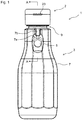
Fig. 1 is a front view of adelaminatable container 1 according to a first embodiment of the present invention. -
Fig. 2A is a cross-sectional view taken along A-A inFig. 1 , andFig. 2B is an enlarged cross-sectional view of acap 2 of thedelaminatable container 1 inFig. 2A and illustrates a state where acap cover 22 is opened. -
Fig. 3A is a front view of acheck valve 25 of thecap 2,Fig. 3B is a perspective view of adischarge member 26 of thecap 2 taken from above, andFig. 3C is a perspective view of thedischarge member 26 taken from below. -
Fig. 4A is an enlarged cross-sectional view of acap 2 according to a modification of the present invention, andFig. 4B is a perspective view illustrating adischarge member 26 and aspacer 27 of thecap 2 inFig. 4A . - Embodiments of the present invention are described below. Various characteristics in the embodiments described below may be combined with each other. Each characteristic is independently inventive.
- As illustrated in
Figs. 1 and2A , adelaminatable container 1 in an embodiment of the present invention includes acap 2 and acontainer body 3. Thecontainer body 3 is provided with avalve member 5, astorage portion 7 to store the contents, and amouth 9 to discharge the contents from thestorage portion 7. In the present embodiment, thecap 2 is press fitted, and as illustrated inFig. 2A , thecap 2 is mounted by engaging anengagement section 9e formed in themouth 9 of thecontainer body 3 with an engagedsection 24e formed in thecap 2. Noted that thecap 2 may be mounted by threading. - As illustrated in
Fig. 2A , thecontainer body 3 includes anouter layer 11 and aninner layer 13 in thestorage portion 7 and themouth 9, where theouter layer 11 constitutes anouter shell 12 and theinner layer 13 constitutes aninner bag 14. Due to delamination of theinner layer 13 from theouter layer 11 with a decrease in the contents, theinner bag 14 separates from theouter shell 12 to be shrunk. Preliminary delamination is sometimes performed to delaminate theinner layer 13 from theouter layer 11 before storage of the contents in thestorage portion 7. In this case, theinner layer 13 is contacted with theouter layer 11 by blowing air or storing the contents in thestorage portion 7 after preliminary delamination. Theinner layer 13 then separates from theouter layer 11 with a decrease in the contents. Meanwhile, when preliminary delamination is not performed, theinner layer 13 is delaminated from theouter layer 11 in discharge of the contents to separate from theouter layer 11. - The
valve member 5 is, as illustrated inFigs. 2A and 2B , inserted into afresh air inlet 15 formed in thestorage portion 7 to regulate entrance and exit of air between the outside and a space G between theouter shell 12 and theinner bag 14. The configuration examples of thevalve member 5 include a configuration where a gap between thevalve member 5 and an edge of thefresh air inlet 15 is opened and closed by movement of thevalve member 5 for opening and closing of thefresh air inlet 15 by thevalve member 5 and a configuration where thevalve member 5 itself is provided with a through hole and an on-off valve, which acts to open and close the through hole for opening and closing of thefresh air inlet 15. In addition, configurations without providing thevalve member 5 are allowed to regulate entrance and exit of air by placing a filter on thefresh air inlet 15 or by simply closing thefresh air inlet 15 with a finger or the like for discharging the contents. Thefresh air inlet 15 may be provided in themouth 9 to use a cap having a check valve in communication with thefresh air inlet 15. - The
valve member 5 in any of the above configurations is configured to allow compression of theinner bag 14 by closing thefresh air inlet 15 when theouter shell 12 is compressed to introduce fresh air into the space G when the compressive force to theouter shell 12 is released. - The
storage portion 7 is covered with a shrink film after thevalve member 5 is mounted. At this point, to avoid interference of thevalve member 5 with the shrink film, thevalve member 5 is mounted to a valvemember mounting recess 7a provided in the. In addition, not to tightly close the valvemember mounting recess 7a with the shrink film, anair circulation groove 7b is provided that extends in the direction from the valvemember mounting recess 7a to the mouth 9 (refer toFig. 1 ). - Regarding the layer structure of the
container body 3, theouter layer 11 is formed thicker than theinner layer 13 so as to increase the restorability thereof. Theouter layer 11 is formed of, for example, low-density polyethylene, linear low-density polyethylene, high-density polyethylene, polypropylene, an ethylene-propylene copolymer, or a mixture thereof, or the like. Theouter layer 11 may have a multilayer structure. Theinner layer 13 preferably has a multilayer structure. Examples of the layer in contact with theouter layer 11 include an EVOH layer 13a of an ethylene-vinyl alcohol copolymer (EVOH) resin, and examples of the layer in contact with the contents include an inner surface layer 13b of polyolefin, such as low-density polyethylene, linear low-density polyethylene, high-density polyethylene, polypropylene, an ethylene-propylene copolymer, and a mixture thereof. The adhesion layer 13c is preferably used between the EVOH layer and the inner surface layer. - Then, referring to
Fig. 2B andFigs. 3A to 3C , thecap 2 is described. Thecap 2 in the present embodiment includes, as illustrated inFig. 2B , acap body 21 and acap cover 22, which are formed of a synthetic resin. Thecap body 21 and thecap cover 22 are connected by ahinge 23 to allow opening and closing of thecap cover 22. Thecap body 21 is composed of three members of amain cap member 24, acheck valve 25, and adischarge member 26 as the discharge portion. The synthetic resin to form thecheck valve 25 is more elastic than the synthetic resin forming the other members. For example, thecheck valve 25 is formed of a polyethylene elastomer and the other members are formed of polypropylene. - The
main cap member 24 is configured with a cylindrical outer tube section 24o, a cylindricalinner tube section 24i concentrically disposed inside the outer tube section 24o, and anannular portion 24r connecting upper ends of the outer tube section 24o and theinner tube section 24i with each other. The outer tube section 24o has a lower inner circumferential surface having the engagedsection 24e formed to be engaged with theengagement section 9e of themouth 9. Theinner tube section 24i has a lower inner circumferential surface, where anannular valve seat 24s is formed that extends diagonally above toward the radial center and has aflow aperture 24h at the center. Thevalve seat 24s has an inner circumferential surface 24s1 in a tapered shape inclined above. Theinner tube section 24i has an upper inner circumferential surface, where afitting recess 24f is formed over the entire circumference. - The
check valve 25 is, as illustrated inFigs. 2B and3A , formed of avalve body 25b, fourelastic pieces 25p, and a circularouter frame 25f. Thevalve body 25b is a member in a domical shape having an upwardly curved cross-sectional shape (refer toFig. 2B ) and having a circular plan view (refer toFig. 3A ) and has aspherical convexity 25s formed at the center of its upper surface. Thevalve body 25b has an outer circumferential portion 25b1 in a tapered shape inclined below to be seated on the innercircumferential surface 24svalve seat 24s and is configured to open and close theflow aperture 24h by thevalve body 25b being separated from or seated on thevalve seat 24s. Theflow aperture 24h and thecorresponding valve body 25b do not have to be in a circular shape and may be in in a polygonal shape or an annular shape. Eachelastic piece 25p extends, as illustrated inFig. 2B , diagonally above in a somewhat curved manner radially from the outer circumferential portion of thevalve body 25b and is connected to an upper end of an inner circumferential surface of theouter frame 25f. The fourelastic pieces 25p are provided every 90° over the entire circumference, and four openings 25o to flow the contents are formed of two of the adjacentelastic pieces 25p, theouter frame 25f, and thevalve body 25b. The fourelastic pieces 25p bias thevalve body 25b in the seating direction as the biasing member. The number ofelastic pieces 25p is not limited to four and may be two, three, five or more. Noted that, to transfer the biasing force to thevalve body 25b, theelastic pieces 25p preferably extend radially. Theouter frame 25f is disposed to abut on an inner wall surface of theinner tube section 24i in an upper area of thevalve seat 24s of themain cap member 24. In the present embodiment, thevalve body 25b, theelastic pieces 25p, and theouter frame 25f of thecheck valve 25 are formed integrally as a single piece. - The
discharge member 26 is provided with, as illustrated inFigs. 2B ,3A, and 3B , atubular support section 26s fitted to theinner tube section 24i of themain cap member 24, atubular guide section 26g disposed concentrically with thetubular support section 26s and having anoutlet 26m, and asheet disk section 26d integrally connecting thetubular guide section 26g and an upper edge of thetubular support section 26s as a single piece. On the upper edge of thetubular support section 26s, aflange 26b outwardly extending in a radial direction is formed and configured to engage with an inner edge of theannular portion 24r of themain cap member 24. Thetubular support section 26s has an outer circumferential surface with anannular rib 26r formed over the entire circumference to be fitted to thefitting recess 24f of themain cap member 24. When themain cap member 24 is fitted to thedischarge member 26, a lower surface of thetubular support section 26s abuts on an upper surface of theouter frame 25f of thecheck valve 25 to fix thecheck valve 25. In this state, thevalve seat 24s and theinner tube section 24i of themain cap member 24 and thedischarge member 26 form an intermediate space S (refer toFig. 2B ) to allow displacement of thevalve body 25b in the intermediate space S. - In addition, the
discharge member 26 in the present embodiment is provided with, as illustrated inFigs. 2B and3B , a plurality ofprojections 26p protruding toward thevalve body 25b in a position facing thevalve body 25b on a surface on the intermediate space S side. In the present embodiment, sixprojections 26p are provided at regular intervals over the entire circumference (refer toFig. 3B ). Theprojections 26p function as the displacement restricting section to restrict the maximum displacement in the intermediate space S of thevalve body 25b of thecheck valve 25, and for example, preferably restricts the maximum displacement with reference (zero displacement) to thevalve body 25b seated on thevalve seat 24s to be 0.8 times or less a diameter of theflow aperture 24h (that is, inner diameter ofvalve seat 24s) and even more preferably to be 0.4 times or less. The displacement is preferably restricted to be from 0.01 times to 0.2 times the diameter of theflow aperture 24h, preferably from 0.05 times to 0.1 times, more preferably from 0.06 times to 0.09 times, and even more preferably from 0.07 times to 0.08 times. Specifically, this value is, for example, 0.05, 0.055, 0.06, 0.065, 0.07, 0.075, 0.08, 0.085, 0.09, 0.095, 0.1, 0.2, 0.4, and 0.8 times or it may be in a range between any two values exemplified here. Such an actual displacement is preferably 1.5 mm or less, preferably from 0.4 to 0.8 mm, more preferably from 0.5 to 0.7 mm, and even more preferably from 0.65 to 0.75 mm. Specifically, this value is, for example, 0.4, 0.45, 0.5, 0.55, 0.6, 0.65, 0.7, 0.75, and 0.8 mm or it may be in a range between any two values exemplified here. Naturally, the maximum displacement may be reduced by increasing the degree of protrusion of theprojections 26p and the maximum displacement may be increased by reducing the degree of protrusion of theprojections 26p. The number ofprojections 26p is not limited to six as long as operations of thevalve body 25b is restricted, and may be five or less or seven or more. Noted that sufficient gaps are preferably provided between theprojections 26p to allow discharge of the contents even when thevalve body 25b gets close to or abuts on theprojections 26p. - Then, operations of the
cap 2 according to the present embodiment are described. - For discharging the contents, the
cap cover 22 is opened to expose thedischarge member 26, thecontainer body 3 is tilted to direct thetubular guide section 26g below, and thestorage portion 7 of thecontainer body 3 is squeezed. Thevalve body 25b is lifted from thevalve seat 24s due to pressure rise in the storage portion 7 (inner bag 14), causing opening of thecheck valve 25 to discharge the contents in thestorage portion 7 through theflow aperture 24h and the intermediate space S from theoutlet 26m. - Then, after a required amount of the contents is discharged, the
container body 3 is returned to an upright position and the squeezing of thestorage portion 7 is stopped, thereby reducing the internal pressure of thestorage portion 7 and closing thecheck valve 25 due to the biasing force of theelastic pieces 25p. Accordingly, an incoming flow of fresh air from theflow aperture 24h into the storage portion 7 (inner bag 14) is prevented, and fresh air thus does not enter theinner bag 14 to inhibit content degradation. - When a sudden force happens to be applied without realizing how strong it should be for discharging the contents by squeezing the
storage portion 7 of thecontainer body 3, thevalve body 25b sometimes moves a lot to discharge more than an expected amount of the contents. There is another problem that squeezing with a weaker force after applying a sudden force causes sudden closing of thevalve body 25b in reaction to wide opening thevalve body 25b due to the biasing force of theelastic pieces 25p and repeating this cycle creates pulsation that results in degradation of usability. However, thecap 2 in the present embodiment has thedischarge member 26 provided with theprojections 26p to restrict the maximum displacement of thevalve body 25b to the predetermined amount described above, thereby preventing opening of thevalve body 25b more than necessary to allow improving the usability. In the present embodiment, theprojections 26p are integrally formed with thedischarge member 26 as a single piece and thus the displacement restricting section is readily configured only by changing the die shape of the discharge member without incorporating another member. - The present invention is allowed to be carried out in the following embodiments.
- Although the
projections 26p formed in thedischarge member 26 are used as the displacement restricting section to restrict the displacement of thevalve body 25b in the above embodiment, the displacement restricting section is not limited to such a configuration. For example, as illustrated inFigs. 4A and 4B , aspacer 27 having a throughhole 27h, as a separate member from thedischarge member 26, is placed on the surface on the intermediate space S side of thedischarge member 26 to configure the displacement restricting section withprojections 27p formed with thespacer 27. Specifically, thespacer 27 has a thinannular portion 27d with an outer diameter approximately identical to the inner diameter of thetubular support section 26s of thedischarge member 26, a plurality ofarms 27a extending from the inner circumferential surface of theannular portion 27d toward the radial center, andprojections 27p axially protruding from the ends of therespective arms 27a. Thearms 27a and theprojections 27p are formed at regular intervals over the entire circumference. Use of thespacer 27 in such a configuration as the displacement restricting section allows restriction of the displacement of thevalve body 25b to improve the usability during discharge of the contents. In addition, by preparing a plurality ofspacers 27 that are different in the length of theprojections 27p and changing thespacer 27 to be mounted to thedischarge member 26 in accordance with the application of the container and the type of contents, thecap 2 with appropriate usability in accordance with intended use is readily manufactured without changing the shapes of the other members. - In addition, as the displacement restricting section to restrict the displacement of the
valve body 25b, projection(s) formed on a surface on thedischarge member 26 side of thevalve body 25b may be used. In this case, the projection on thevalve body 25b side abuts on the surface on the intermediate space S side of thedischarge member 26 to restrict the displacement of thevalve body 25b itself. - The
cap 2 of the present invention may be used for containers other than thedelaminatable container 1, for example, a monolayer container in which the entire container is shrunk with discharge of the contents. - The present invention is described below further in detail using Test Examples. The present invention is, however, not at all limited to Test Examples below. In the following tests, the
cap 2 had theoutlet 26m with a diameter of 4.0 mm, theflow aperture 24h (valve body 25b) with a diameter of 8.0 mm. The contents were a liquid (soy sauce), and thecontainer body 3 had a volume of 360 ml. In the tests, 11 test subjects performed discharge of the contents (liquid) in thecontainer body 3 twice per subject and evaluated Samples having displacement restricting section (projections 26p) that caused thevalve bodies 25b to have the four maximum displacements below and Comparative Example having no displacement restricting section from three perspectives of "whether the contents were discharged in an intended position", "whether the contents were discharged in a satisfactory manner", and "whether the contents were discharged in an appropriate amount". The evaluation was made in five grades (from 1 as poor to 5 as good).Sample 10.4 mm (0.05 times of the flow aperture diameter) Sample 20.5 mm (0.0625 times of the same) Sample 30.6 mm (0.075 times of the same) Sample 4 0.7 mm (0.0875 times of the same) Comparative Example 2.0 mm or more [Table 1] Maximum Displacement of Valve Body 25bDischarged in Intended Position? Discharged in Satisfactory Manner? Discharged in Appropriate Amount? Sample 10.4 mm 2.0 1.5 1.7 Sample 20.5 mm 3.6 3.4 3.5 Sample 30.6 mm 3.8 4.0 4.0 Sample 4 0.7 mm 3.8 3.7 3.7 Comparative Example 2 mm or more 2.2 2.0 2.7 Poor1<2<3<4<5 Good - Table 1 shows results of the above tests. Each value in Table 1 was obtained by rounding off an average of the evaluations by the 11 subjects to the first decimal place. As shown in Table 1, from any of the three perspectives, the scores get better with each increase in displacement within the maximum displacement ranging from 0.4 mm to 0.6 mm and the scores for 0.7 mm are somewhat worse than those for 0.6 mm. In comparison with Comparative Example, only for the maximum displacement of 0.4 mm, the results were worse than Comparative Example and the users felt discomfort. This is considered because the amount of discharge was not as much as expected relative to the degree of squeezing. The above findings indicate that the maximum displacement of the
valve body 25b is preferably from 0.4 to 0.8 mm, more preferably from 0.5 to 0.7 mm, and even more preferably from 0.55 to 0.65 mm. Similarly, the maximum displacement of thevalve body 25b is preferably from 0.05 times to 0.1 times the diameter of theflow aperture 24h, more preferably from 0.06 times to 0.09 times, and even more preferably from 0.07 times to 0.08 times. -
- 1: Delaminatable Container,
- 2: Cap,
- 3: Container Body,
- 5: Valve Member,
- 7: Storage Portion,
- 9: Mouth,
- 15: Fresh Air Inlet,
- 21: Cap Body,
- 24: Main Cap Member,
- 24h: Flow Aperture,
- 24i: Inner Tube Section,
- 24o: Outer Tube Section,
- 24r: Annular Portion,
- 24s: Valve Seat,
- 25: Check Valve, 2
- 5b: Valve Body,
- 25f: Outer Frame,
- 25p: Elastic Piece,
- 26: Discharge Member,
- 26d: Disk Section,
- 26g: Tubular Guide Section,
- 26m: Outlet, 26p: Projection,
- 26s: Tubular Support Section,
- S: Intermediate Space.
Claims (9)
- A cap comprising a cap body to be fitted to a mouth of a container, wherein
the cap is configured to include: a valve seat having a flow aperture; a valve body to be separated from or seated on the valve seat so as to open and close the flow aperture; and a biasing member to bias the valve body in a seating direction, and configured to increase a flow area in which contents flow with an increase in a displacement of the valve body, and
the cap further includes a displacement restricting section to restrict the displacement of the valve body. - The cap of Claim 1, wherein the displacement restricting section restricts the displacement of the valve body to be 0.8 times or less a diameter of the flow aperture.
- The cap of Claim 1, wherein the displacement restricting section restricts the displacement of the valve body to 1.5 mm or less.
- The cap of Claim 1, wherein the displacement restricting section restricts the displacement of the valve body from 0.4 to 0.8 mm.
- The cap of any one of Claims 1 to 4, wherein the biasing member is formed of a plurality of elastic pieces radially extending from an outer circumferential portion of the valve body.
- The cap of any one of Claims 1 to 5, wherein the cap body includes: an inner tube section having the valve seat; and a discharge portion mounted to the inner tube section and having an outlet, the inner tube section and the discharge portion forming an intermediate space, and
the cap is configured to displace the valve body in the intermediate space. - The cap of Claim 6, wherein the displacement restricting section is formed of a plurality of projections formed on a surface on a side of the intermediate space of the discharge portion.
- The cap of Claim 6, wherein the displacement restricting section is formed of a spacer disposed between the discharge portion and the check valve.
- A delaminatable container comprising a container body having an outer shell and an inner bag, the inner bag to be shrunk with a decrease in the contents, wherein
the cap of any one of Claims 1 to 8 is fitted to a mouth of the container body.
Applications Claiming Priority (2)
| Application Number | Priority Date | Filing Date | Title |
|---|---|---|---|
| JP2017014537A JP7092980B2 (en) | 2017-01-30 | 2017-01-30 | Cap and laminated stripping container |
| PCT/JP2018/002523 WO2018139591A1 (en) | 2017-01-30 | 2018-01-26 | Cap and separable laminate container |
Publications (3)
| Publication Number | Publication Date |
|---|---|
| EP3575236A1 true EP3575236A1 (en) | 2019-12-04 |
| EP3575236A4 EP3575236A4 (en) | 2020-02-26 |
| EP3575236B1 EP3575236B1 (en) | 2022-04-06 |
Family
ID=62979449
Family Applications (1)
| Application Number | Title | Priority Date | Filing Date |
|---|---|---|---|
| EP18744266.0A Active EP3575236B1 (en) | 2017-01-30 | 2018-01-26 | Cap and separable laminate container |
Country Status (7)
| Country | Link |
|---|---|
| US (1) | US10954043B2 (en) |
| EP (1) | EP3575236B1 (en) |
| JP (1) | JP7092980B2 (en) |
| KR (1) | KR102570838B1 (en) |
| CN (1) | CN110062739B (en) |
| TW (1) | TWI756344B (en) |
| WO (1) | WO2018139591A1 (en) |
Families Citing this family (22)
| Publication number | Priority date | Publication date | Assignee | Title |
|---|---|---|---|---|
| US10822135B2 (en) * | 2015-12-03 | 2020-11-03 | Kyoraku Co., Ltd. | Delaminatable container |
| CN110382371A (en) * | 2017-03-15 | 2019-10-25 | 京洛株式会社 | Laminated peeling container |
| CN110921090B (en) * | 2018-09-20 | 2022-03-29 | 宏全国际股份有限公司 | Non-return bottle cap and non-return valve thereof |
| WO2021028602A1 (en) * | 2019-08-15 | 2021-02-18 | Obrist Closures Switzerland Gmbh | Closure |
| CN110451071B (en) * | 2019-08-25 | 2021-07-09 | 台州市祥珑食品容器科技股份有限公司 | Bottle cap and packaging bottle |
| US11647860B1 (en) | 2022-05-13 | 2023-05-16 | Sharkninja Operating Llc | Flavored beverage carbonation system |
| US12213617B2 (en) | 2022-05-13 | 2025-02-04 | Sharkninja Operating Llc | Flavored beverage carbonation process |
| US11751585B1 (en) | 2022-05-13 | 2023-09-12 | Sharkninja Operating Llc | Flavored beverage carbonation system |
| US12096880B2 (en) | 2022-05-13 | 2024-09-24 | Sharkninja Operating Llc | Flavorant for beverage carbonation system |
| US12539500B2 (en) | 2022-08-31 | 2026-02-03 | Sharkninja Operating Llc | Additive containers |
| CN115477098B (en) * | 2022-09-27 | 2023-12-01 | 台州市祥珑食品容器科技股份有限公司 | Packaging bottle with collapsible inner bag and manufacturing method of packaging bottle with collapsible inner bag |
| US11738988B1 (en) | 2022-11-17 | 2023-08-29 | Sharkninja Operating Llc | Ingredient container valve control |
| US11745996B1 (en) | 2022-11-17 | 2023-09-05 | Sharkninja Operating Llc | Ingredient containers for use with beverage dispensers |
| US11634314B1 (en) | 2022-11-17 | 2023-04-25 | Sharkninja Operating Llc | Dosing accuracy |
| US12103840B2 (en) | 2022-11-17 | 2024-10-01 | Sharkninja Operating Llc | Ingredient container with sealing valve |
| US12084334B2 (en) | 2022-11-17 | 2024-09-10 | Sharkninja Operating Llc | Ingredient container |
| USD1091308S1 (en) | 2022-12-23 | 2025-09-02 | Sharkninja Operating Llc | Ingredient container |
| USD1092208S1 (en) | 2022-12-23 | 2025-09-09 | Sharkninja Operating Llc | Cap of ingredient container |
| US12116257B1 (en) | 2023-03-22 | 2024-10-15 | Sharkninja Operating Llc | Adapter for beverage dispenser |
| US11871867B1 (en) | 2023-03-22 | 2024-01-16 | Sharkninja Operating Llc | Additive container with bottom cover |
| US11925287B1 (en) | 2023-03-22 | 2024-03-12 | Sharkninja Operating Llc | Additive container with inlet tube |
| US12005408B1 (en) | 2023-04-14 | 2024-06-11 | Sharkninja Operating Llc | Mixing funnel |
Family Cites Families (29)
| Publication number | Priority date | Publication date | Assignee | Title |
|---|---|---|---|---|
| US2128035A (en) * | 1937-05-20 | 1938-08-23 | Harold J Boetel | Collapsible tube or container |
| FR2551030B1 (en) * | 1983-07-15 | 1989-08-18 | Yoshida Industry Co | TUBE CONTAINER FOR CONTAINING SEMI-FLUID MATERIAL |
| US4785978A (en) * | 1987-03-02 | 1988-11-22 | Japan Crown Cork Co., Ltd. | Container closure provided with automatic opening-closing mechanism |
| EP0587556A1 (en) * | 1991-06-07 | 1994-03-23 | 153981 Canada Inc. | Inverted dispenser |
| IT221941Z2 (en) | 1991-10-10 | 1994-12-29 | Sofar Spa | NON-RETURN VALVE CAN BE USED IN PARTICULAR IN A LIQUID PRESSURE DISPENSING CONTAINER |
| EP1873076B1 (en) * | 1994-11-17 | 2012-01-25 | Yoshino Kogyosho Co., Ltd. | Container with pump for discharging bubbles |
| DE10109064A1 (en) * | 2001-02-24 | 2002-09-05 | Beiersdorf Ag | Opening system with back ventilation mechanism |
| US6616012B2 (en) * | 2001-07-27 | 2003-09-09 | Richard C. G. Dark | Fluid dispensing valve and method of use |
| FR2828679B1 (en) * | 2001-08-17 | 2003-10-24 | Cebal | FLEXIBLE TUBE WITH AIR RETURN DISTRIBUTOR HEAD |
| JP2004067099A (en) | 2002-06-10 | 2004-03-04 | Katsutoshi Masuda | Valve mechanism |
| JP2004083013A (en) * | 2002-06-26 | 2004-03-18 | Katsutoshi Masuda | Valve mechanism |
| US7249694B2 (en) * | 2002-07-26 | 2007-07-31 | Masatoshi Masuda | Valve mechanism for tube-type fluid container |
| US6832706B2 (en) * | 2003-01-10 | 2004-12-21 | Alcoa Closure Systems International | Dispensing closure |
| ITMI20030584U1 (en) * | 2003-12-12 | 2005-06-13 | Intercos Italiana | APPLICABLE DEVICE FOR COSMETIC PRODUCTS |
| EP2558380B1 (en) * | 2010-04-12 | 2016-06-01 | Hoffmann Neopac AG | Tube with one-way valve for discharge regulation in tubes and method for manufacturing such a one-way valve |
| US8608034B2 (en) * | 2011-02-18 | 2013-12-17 | Berry Plastics Corporation | Dispensing valve |
| JP5727888B2 (en) * | 2011-02-28 | 2015-06-03 | 株式会社吉野工業所 | Discharge container |
| JP5667010B2 (en) * | 2011-06-09 | 2015-02-12 | 株式会社吉野工業所 | Discharge container |
| BR112014005552A2 (en) * | 2011-09-13 | 2017-03-21 | Aptargroup Inc | distribution valve |
| JP2013241197A (en) * | 2012-05-21 | 2013-12-05 | Daiwa Can Co Ltd | Cap |
| JP6100183B2 (en) * | 2014-02-21 | 2017-03-22 | 株式会社トーヨー工芸工業 | Liquid leak prevention cap for double containers |
| US20170107024A1 (en) * | 2014-03-25 | 2017-04-20 | Guala Pack S.P.A. | Spout for flexible pouch with obturator device |
| KR102110129B1 (en) * | 2014-05-14 | 2020-06-08 | 도쿄 라이트 고교 가부시키가이샤 | Cap |
| JP5963323B2 (en) * | 2014-08-05 | 2016-08-03 | 東京ライト工業株式会社 | cap |
| KR101636820B1 (en) * | 2014-10-27 | 2016-07-07 | 주식회사 아이팩 | Contents of the tube container spill-proof valve |
| JP6478564B2 (en) * | 2014-11-06 | 2019-03-06 | 東京ライト工業株式会社 | Pouring spout |
| JP6602088B2 (en) * | 2015-08-06 | 2019-11-06 | 三笠産業株式会社 | cap |
| US10822135B2 (en) * | 2015-12-03 | 2020-11-03 | Kyoraku Co., Ltd. | Delaminatable container |
| US10781017B2 (en) * | 2016-05-20 | 2020-09-22 | Tokyo Light Industry Co., Ltd. | Cap and discharge container |
-
2017
- 2017-01-30 JP JP2017014537A patent/JP7092980B2/en active Active
-
2018
- 2018-01-23 TW TW107102350A patent/TWI756344B/en active
- 2018-01-26 EP EP18744266.0A patent/EP3575236B1/en active Active
- 2018-01-26 US US16/480,064 patent/US10954043B2/en active Active
- 2018-01-26 WO PCT/JP2018/002523 patent/WO2018139591A1/en not_active Ceased
- 2018-01-26 CN CN201880004968.8A patent/CN110062739B/en active Active
- 2018-01-26 KR KR1020197021177A patent/KR102570838B1/en active Active
Also Published As
| Publication number | Publication date |
|---|---|
| US10954043B2 (en) | 2021-03-23 |
| KR102570838B1 (en) | 2023-08-24 |
| KR20190112722A (en) | 2019-10-07 |
| JP2018122862A (en) | 2018-08-09 |
| EP3575236A4 (en) | 2020-02-26 |
| TWI756344B (en) | 2022-03-01 |
| EP3575236B1 (en) | 2022-04-06 |
| WO2018139591A1 (en) | 2018-08-02 |
| TW201833001A (en) | 2018-09-16 |
| JP7092980B2 (en) | 2022-06-29 |
| CN110062739B (en) | 2023-06-16 |
| CN110062739A (en) | 2019-07-26 |
| US20190375561A1 (en) | 2019-12-12 |
Similar Documents
| Publication | Publication Date | Title |
|---|---|---|
| EP3575236B1 (en) | Cap and separable laminate container | |
| CN109715516B (en) | Discharge container | |
| AU2012333706B2 (en) | Discharge container | |
| CN105228909B (en) | It is laminated bottle | |
| EP3375723B1 (en) | Double-walled container | |
| EP3248895A1 (en) | Delamination container | |
| US10781017B2 (en) | Cap and discharge container | |
| US10723500B2 (en) | Delamination container, method for attaching cap to delamination container, and method for manufacturing delamination container | |
| KR102172655B1 (en) | Elastic member and pump assembly including the same | |
| JP2018122860A (en) | Delamination container | |
| JP2014208546A (en) | Laminated bottle | |
| US20200140156A1 (en) | System and kit for a child resistant sealing can lid | |
| JP6710468B2 (en) | Discharge container | |
| JP7292788B2 (en) | Inverted double container | |
| TWI784106B (en) | Caps and Laminated Stripping Containers | |
| KR102517952B1 (en) | A discharge bottle | |
| JP6896342B2 (en) | Double container cap | |
| JP6578237B2 (en) | Discharge container | |
| JP7031992B2 (en) | Double container cap | |
| JP2018002216A (en) | Container with gas vent mechanism | |
| JP6499942B2 (en) | Stacked bottles | |
| CN210823561U (en) | Sealing assembly for bottled products and bottled products adopting same | |
| JP2002173155A (en) | Circular stopper | |
| JP2019059521A (en) | Discharge container | |
| JP2021006466A (en) | Spouting cap for double container and double container |
Legal Events
| Date | Code | Title | Description |
|---|---|---|---|
| STAA | Information on the status of an ep patent application or granted ep patent |
Free format text: STATUS: THE INTERNATIONAL PUBLICATION HAS BEEN MADE |
|
| PUAI | Public reference made under article 153(3) epc to a published international application that has entered the european phase |
Free format text: ORIGINAL CODE: 0009012 |
|
| STAA | Information on the status of an ep patent application or granted ep patent |
Free format text: STATUS: REQUEST FOR EXAMINATION WAS MADE |
|
| 17P | Request for examination filed |
Effective date: 20190806 |
|
| AK | Designated contracting states |
Kind code of ref document: A1 Designated state(s): AL AT BE BG CH CY CZ DE DK EE ES FI FR GB GR HR HU IE IS IT LI LT LU LV MC MK MT NL NO PL PT RO RS SE SI SK SM TR |
|
| AX | Request for extension of the european patent |
Extension state: BA ME |
|
| A4 | Supplementary search report drawn up and despatched |
Effective date: 20200128 |
|
| RIC1 | Information provided on ipc code assigned before grant |
Ipc: B65D 47/20 20060101AFI20200122BHEP |
|
| DAV | Request for validation of the european patent (deleted) | ||
| DAX | Request for extension of the european patent (deleted) | ||
| STAA | Information on the status of an ep patent application or granted ep patent |
Free format text: STATUS: EXAMINATION IS IN PROGRESS |
|
| 17Q | First examination report despatched |
Effective date: 20210416 |
|
| GRAP | Despatch of communication of intention to grant a patent |
Free format text: ORIGINAL CODE: EPIDOSNIGR1 |
|
| STAA | Information on the status of an ep patent application or granted ep patent |
Free format text: STATUS: GRANT OF PATENT IS INTENDED |
|
| RIC1 | Information provided on ipc code assigned before grant |
Ipc: B05B 11/00 20060101ALI20210924BHEP Ipc: B05B 11/04 20060101ALI20210924BHEP Ipc: B65D 47/20 20060101AFI20210924BHEP |
|
| INTG | Intention to grant announced |
Effective date: 20211103 |
|
| GRAS | Grant fee paid |
Free format text: ORIGINAL CODE: EPIDOSNIGR3 |
|
| GRAA | (expected) grant |
Free format text: ORIGINAL CODE: 0009210 |
|
| STAA | Information on the status of an ep patent application or granted ep patent |
Free format text: STATUS: THE PATENT HAS BEEN GRANTED |
|
| AK | Designated contracting states |
Kind code of ref document: B1 Designated state(s): AL AT BE BG CH CY CZ DE DK EE ES FI FR GB GR HR HU IE IS IT LI LT LU LV MC MK MT NL NO PL PT RO RS SE SI SK SM TR |
|
| REG | Reference to a national code |
Ref country code: GB Ref legal event code: FG4D |
|
| REG | Reference to a national code |
Ref country code: CH Ref legal event code: EP |
|
| REG | Reference to a national code |
Ref country code: AT Ref legal event code: REF Ref document number: 1481151 Country of ref document: AT Kind code of ref document: T Effective date: 20220415 |
|
| REG | Reference to a national code |
Ref country code: IE Ref legal event code: FG4D |
|
| REG | Reference to a national code |
Ref country code: DE Ref legal event code: R096 Ref document number: 602018033396 Country of ref document: DE |
|
| REG | Reference to a national code |
Ref country code: LT Ref legal event code: MG9D |
|
| REG | Reference to a national code |
Ref country code: NL Ref legal event code: MP Effective date: 20220406 |
|
| REG | Reference to a national code |
Ref country code: AT Ref legal event code: MK05 Ref document number: 1481151 Country of ref document: AT Kind code of ref document: T Effective date: 20220406 |
|
| PG25 | Lapsed in a contracting state [announced via postgrant information from national office to epo] |
Ref country code: NL Free format text: LAPSE BECAUSE OF FAILURE TO SUBMIT A TRANSLATION OF THE DESCRIPTION OR TO PAY THE FEE WITHIN THE PRESCRIBED TIME-LIMIT Effective date: 20220406 |
|
| PG25 | Lapsed in a contracting state [announced via postgrant information from national office to epo] |
Ref country code: SE Free format text: LAPSE BECAUSE OF FAILURE TO SUBMIT A TRANSLATION OF THE DESCRIPTION OR TO PAY THE FEE WITHIN THE PRESCRIBED TIME-LIMIT Effective date: 20220406 Ref country code: PT Free format text: LAPSE BECAUSE OF FAILURE TO SUBMIT A TRANSLATION OF THE DESCRIPTION OR TO PAY THE FEE WITHIN THE PRESCRIBED TIME-LIMIT Effective date: 20220808 Ref country code: NO Free format text: LAPSE BECAUSE OF FAILURE TO SUBMIT A TRANSLATION OF THE DESCRIPTION OR TO PAY THE FEE WITHIN THE PRESCRIBED TIME-LIMIT Effective date: 20220706 Ref country code: LT Free format text: LAPSE BECAUSE OF FAILURE TO SUBMIT A TRANSLATION OF THE DESCRIPTION OR TO PAY THE FEE WITHIN THE PRESCRIBED TIME-LIMIT Effective date: 20220406 Ref country code: HR Free format text: LAPSE BECAUSE OF FAILURE TO SUBMIT A TRANSLATION OF THE DESCRIPTION OR TO PAY THE FEE WITHIN THE PRESCRIBED TIME-LIMIT Effective date: 20220406 Ref country code: GR Free format text: LAPSE BECAUSE OF FAILURE TO SUBMIT A TRANSLATION OF THE DESCRIPTION OR TO PAY THE FEE WITHIN THE PRESCRIBED TIME-LIMIT Effective date: 20220707 Ref country code: FI Free format text: LAPSE BECAUSE OF FAILURE TO SUBMIT A TRANSLATION OF THE DESCRIPTION OR TO PAY THE FEE WITHIN THE PRESCRIBED TIME-LIMIT Effective date: 20220406 Ref country code: ES Free format text: LAPSE BECAUSE OF FAILURE TO SUBMIT A TRANSLATION OF THE DESCRIPTION OR TO PAY THE FEE WITHIN THE PRESCRIBED TIME-LIMIT Effective date: 20220406 Ref country code: BG Free format text: LAPSE BECAUSE OF FAILURE TO SUBMIT A TRANSLATION OF THE DESCRIPTION OR TO PAY THE FEE WITHIN THE PRESCRIBED TIME-LIMIT Effective date: 20220706 Ref country code: AT Free format text: LAPSE BECAUSE OF FAILURE TO SUBMIT A TRANSLATION OF THE DESCRIPTION OR TO PAY THE FEE WITHIN THE PRESCRIBED TIME-LIMIT Effective date: 20220406 |
|
| PG25 | Lapsed in a contracting state [announced via postgrant information from national office to epo] |
Ref country code: RS Free format text: LAPSE BECAUSE OF FAILURE TO SUBMIT A TRANSLATION OF THE DESCRIPTION OR TO PAY THE FEE WITHIN THE PRESCRIBED TIME-LIMIT Effective date: 20220406 Ref country code: PL Free format text: LAPSE BECAUSE OF FAILURE TO SUBMIT A TRANSLATION OF THE DESCRIPTION OR TO PAY THE FEE WITHIN THE PRESCRIBED TIME-LIMIT Effective date: 20220406 Ref country code: LV Free format text: LAPSE BECAUSE OF FAILURE TO SUBMIT A TRANSLATION OF THE DESCRIPTION OR TO PAY THE FEE WITHIN THE PRESCRIBED TIME-LIMIT Effective date: 20220406 Ref country code: IS Free format text: LAPSE BECAUSE OF FAILURE TO SUBMIT A TRANSLATION OF THE DESCRIPTION OR TO PAY THE FEE WITHIN THE PRESCRIBED TIME-LIMIT Effective date: 20220806 |
|
| REG | Reference to a national code |
Ref country code: DE Ref legal event code: R097 Ref document number: 602018033396 Country of ref document: DE |
|
| PG25 | Lapsed in a contracting state [announced via postgrant information from national office to epo] |
Ref country code: SM Free format text: LAPSE BECAUSE OF FAILURE TO SUBMIT A TRANSLATION OF THE DESCRIPTION OR TO PAY THE FEE WITHIN THE PRESCRIBED TIME-LIMIT Effective date: 20220406 Ref country code: SK Free format text: LAPSE BECAUSE OF FAILURE TO SUBMIT A TRANSLATION OF THE DESCRIPTION OR TO PAY THE FEE WITHIN THE PRESCRIBED TIME-LIMIT Effective date: 20220406 Ref country code: RO Free format text: LAPSE BECAUSE OF FAILURE TO SUBMIT A TRANSLATION OF THE DESCRIPTION OR TO PAY THE FEE WITHIN THE PRESCRIBED TIME-LIMIT Effective date: 20220406 Ref country code: EE Free format text: LAPSE BECAUSE OF FAILURE TO SUBMIT A TRANSLATION OF THE DESCRIPTION OR TO PAY THE FEE WITHIN THE PRESCRIBED TIME-LIMIT Effective date: 20220406 Ref country code: DK Free format text: LAPSE BECAUSE OF FAILURE TO SUBMIT A TRANSLATION OF THE DESCRIPTION OR TO PAY THE FEE WITHIN THE PRESCRIBED TIME-LIMIT Effective date: 20220406 Ref country code: CZ Free format text: LAPSE BECAUSE OF FAILURE TO SUBMIT A TRANSLATION OF THE DESCRIPTION OR TO PAY THE FEE WITHIN THE PRESCRIBED TIME-LIMIT Effective date: 20220406 |
|
| PLBE | No opposition filed within time limit |
Free format text: ORIGINAL CODE: 0009261 |
|
| STAA | Information on the status of an ep patent application or granted ep patent |
Free format text: STATUS: NO OPPOSITION FILED WITHIN TIME LIMIT |
|
| 26N | No opposition filed |
Effective date: 20230110 |
|
| PG25 | Lapsed in a contracting state [announced via postgrant information from national office to epo] |
Ref country code: AL Free format text: LAPSE BECAUSE OF FAILURE TO SUBMIT A TRANSLATION OF THE DESCRIPTION OR TO PAY THE FEE WITHIN THE PRESCRIBED TIME-LIMIT Effective date: 20220406 |
|
| PG25 | Lapsed in a contracting state [announced via postgrant information from national office to epo] |
Ref country code: SI Free format text: LAPSE BECAUSE OF FAILURE TO SUBMIT A TRANSLATION OF THE DESCRIPTION OR TO PAY THE FEE WITHIN THE PRESCRIBED TIME-LIMIT Effective date: 20220406 |
|
| REG | Reference to a national code |
Ref country code: CH Ref legal event code: PL |
|
| PG25 | Lapsed in a contracting state [announced via postgrant information from national office to epo] |
Ref country code: LU Free format text: LAPSE BECAUSE OF NON-PAYMENT OF DUE FEES Effective date: 20230126 |
|
| REG | Reference to a national code |
Ref country code: BE Ref legal event code: MM Effective date: 20230131 |
|
| PG25 | Lapsed in a contracting state [announced via postgrant information from national office to epo] |
Ref country code: LI Free format text: LAPSE BECAUSE OF NON-PAYMENT OF DUE FEES Effective date: 20230131 Ref country code: CH Free format text: LAPSE BECAUSE OF NON-PAYMENT OF DUE FEES Effective date: 20230131 |
|
| PG25 | Lapsed in a contracting state [announced via postgrant information from national office to epo] |
Ref country code: BE Free format text: LAPSE BECAUSE OF NON-PAYMENT OF DUE FEES Effective date: 20230131 |
|
| PG25 | Lapsed in a contracting state [announced via postgrant information from national office to epo] |
Ref country code: IT Free format text: LAPSE BECAUSE OF FAILURE TO SUBMIT A TRANSLATION OF THE DESCRIPTION OR TO PAY THE FEE WITHIN THE PRESCRIBED TIME-LIMIT Effective date: 20220406 Ref country code: IE Free format text: LAPSE BECAUSE OF NON-PAYMENT OF DUE FEES Effective date: 20230126 |
|
| PGFP | Annual fee paid to national office [announced via postgrant information from national office to epo] |
Ref country code: GB Payment date: 20240123 Year of fee payment: 7 |
|
| PGFP | Annual fee paid to national office [announced via postgrant information from national office to epo] |
Ref country code: FR Payment date: 20240122 Year of fee payment: 7 |
|
| PG25 | Lapsed in a contracting state [announced via postgrant information from national office to epo] |
Ref country code: MC Free format text: LAPSE BECAUSE OF FAILURE TO SUBMIT A TRANSLATION OF THE DESCRIPTION OR TO PAY THE FEE WITHIN THE PRESCRIBED TIME-LIMIT Effective date: 20220406 |
|
| PG25 | Lapsed in a contracting state [announced via postgrant information from national office to epo] |
Ref country code: MC Free format text: LAPSE BECAUSE OF FAILURE TO SUBMIT A TRANSLATION OF THE DESCRIPTION OR TO PAY THE FEE WITHIN THE PRESCRIBED TIME-LIMIT Effective date: 20220406 |
|
| PG25 | Lapsed in a contracting state [announced via postgrant information from national office to epo] |
Ref country code: BG Free format text: LAPSE BECAUSE OF FAILURE TO SUBMIT A TRANSLATION OF THE DESCRIPTION OR TO PAY THE FEE WITHIN THE PRESCRIBED TIME-LIMIT Effective date: 20220406 |
|
| PG25 | Lapsed in a contracting state [announced via postgrant information from national office to epo] |
Ref country code: BG Free format text: LAPSE BECAUSE OF FAILURE TO SUBMIT A TRANSLATION OF THE DESCRIPTION OR TO PAY THE FEE WITHIN THE PRESCRIBED TIME-LIMIT Effective date: 20220406 |
|
| PG25 | Lapsed in a contracting state [announced via postgrant information from national office to epo] |
Ref country code: CY Free format text: LAPSE BECAUSE OF FAILURE TO SUBMIT A TRANSLATION OF THE DESCRIPTION OR TO PAY THE FEE WITHIN THE PRESCRIBED TIME-LIMIT; INVALID AB INITIO Effective date: 20180126 |
|
| PG25 | Lapsed in a contracting state [announced via postgrant information from national office to epo] |
Ref country code: HU Free format text: LAPSE BECAUSE OF FAILURE TO SUBMIT A TRANSLATION OF THE DESCRIPTION OR TO PAY THE FEE WITHIN THE PRESCRIBED TIME-LIMIT; INVALID AB INITIO Effective date: 20180126 |
|
| GBPC | Gb: european patent ceased through non-payment of renewal fee |
Effective date: 20250126 |
|
| PG25 | Lapsed in a contracting state [announced via postgrant information from national office to epo] |
Ref country code: GB Free format text: LAPSE BECAUSE OF NON-PAYMENT OF DUE FEES Effective date: 20250126 |
|
| PG25 | Lapsed in a contracting state [announced via postgrant information from national office to epo] |
Ref country code: FR Free format text: LAPSE BECAUSE OF NON-PAYMENT OF DUE FEES Effective date: 20250131 |
|
| PG25 | Lapsed in a contracting state [announced via postgrant information from national office to epo] |
Ref country code: TR Free format text: LAPSE BECAUSE OF FAILURE TO SUBMIT A TRANSLATION OF THE DESCRIPTION OR TO PAY THE FEE WITHIN THE PRESCRIBED TIME-LIMIT Effective date: 20220406 |
|
| PGFP | Annual fee paid to national office [announced via postgrant information from national office to epo] |
Ref country code: DE Payment date: 20260121 Year of fee payment: 9 |