EP3575178A1 - Obstacle deflector for a rail vehicle - Google Patents
Obstacle deflector for a rail vehicle Download PDFInfo
- Publication number
- EP3575178A1 EP3575178A1 EP18305679.5A EP18305679A EP3575178A1 EP 3575178 A1 EP3575178 A1 EP 3575178A1 EP 18305679 A EP18305679 A EP 18305679A EP 3575178 A1 EP3575178 A1 EP 3575178A1
- Authority
- EP
- European Patent Office
- Prior art keywords
- obstacle
- support member
- obstacle deflector
- deflector
- carbodyshell
- Prior art date
- Legal status (The legal status is an assumption and is not a legal conclusion. Google has not performed a legal analysis and makes no representation as to the accuracy of the status listed.)
- Granted
Links
Images



Classifications
-
- B—PERFORMING OPERATIONS; TRANSPORTING
- B61—RAILWAYS
- B61F—RAIL VEHICLE SUSPENSIONS, e.g. UNDERFRAMES, BOGIES OR ARRANGEMENTS OF WHEEL AXLES; RAIL VEHICLES FOR USE ON TRACKS OF DIFFERENT WIDTH; PREVENTING DERAILING OF RAIL VEHICLES; WHEEL GUARDS, OBSTRUCTION REMOVERS OR THE LIKE FOR RAIL VEHICLES
- B61F19/00—Wheel guards; Bumpers; Obstruction removers or the like
- B61F19/04—Bumpers or like collision guards
Definitions
- the present invention relates to an obstacle deflector for a rail vehicle.
- An obstacle deflector for a rail vehicle also known as snowplough or pilot, is a device which is usually placed at the front end of a carbodyshell of a rail vehicle, such as a train, and is arranged to deflect possible obstacles present on the railway track that might otherwise derail the train when the latter is travelling along the track. Obstacles should be deflected as early as possible because otherwise they might damage the train, thus resulting in unnecessary maintenance costs.
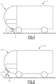
- Figure 1 shows a schematic lateral view of a train 1 having an obstacle deflector 2 which is fixed to the front end of its carbodyshell 4 and is capable of performing the primary task of removing obstacles from the railway track, thus protecting the train 1 from derailment.
- this obstacle deflector 2 is not capable of protecting the carbodyshell 4 from damages, because it happens quite frequently that obstacles firstly hit the cover panel of the carbodyshell 4 and only later they are pushed away by the obstacle deflector 2.
- an obstacle deflector designed according to the EN 15227 standard has usually to be installed in longitudinal direction behind or in a back position below the energy absorber elements, also known as energy dissipation devices, which are fixed, in known manner, to the front end of the carbodyshell 4 and are arranged to absorb the impact energy in case of impacts with obstacles which may be present on the path of the train 1.
- energy absorber elements also known as energy dissipation devices
- the obstacle deflector 2 is usually placed behind them because otherwise, due to the fact that it is a fixed element, in case of crash events it would restrain the energy absorber elements, not allowing their proper functioning.
- the obstacle deflector of the present invention is capable of both removing obstacles present on a railway track and protecting the carbodyshell of a train without requiring modifications to the energy absorber elements usually present on the front end of a carbodyshell of a train.
- the obstacle deflector of the present invention thanks to the fact that of being movable, can be placed in front of the energy absorbers because during a crash scenario it is arranged to slide back without affecting the operation of the energy absorbers.
- the obstacle deflector according to the present invention has the same functionalities as any other fixed mounted deflector of the prior art according to the EN 15227 standard.
- Figure 2 shows a schematic lateral view of a train 10 having an obstacle deflector 12 fixed to the front end of its carbodyshell 14 in a forward position with respect to the prior art, so that obstacles first collide with the obstacle deflector 12 and then are moved away from the railway track.
- the obstacle deflector 12 is mounted in an extended position so as to project forward beyond energy absorber elements of the train 10: when an obstacle approaches the train 10, it firstly impacts the obstacle deflector 12.
- the obstacle deflector 12 pushes the obstacle away from the railway track, otherwise, it moves to a retracted position wherein it does no more project beyond the energy absorber elements.
- Figure 3 shows a lateral view of the train 10 with its obstacle deflector 12 placed under energy absorber elements 22, and another opposed train 10' with its obstacle deflector 12' placed under its energy absorber elements 22'.
- the respective obstacle deflectors 12 and 12' move from the extended position shown in figure 3 , wherein they project beyond the corresponding energy absorber elements 22 an 22', to the retracted position, wherein they do not project beyond the corresponding energy absorber elements 22 an 22', as disclosed herein below in detail.
- the obstacle deflector 12 In order to withstand accidents with obstacles having an impact force level below a threshold, for example equal to 300kN, as indicated in the scenarios disclosed in the EN 15227 standard, the obstacle deflector 12 is positioned, as above indicated, so as to project beyond the energy absorber elements 22, while having at the same time the stability and stiffness required by EN 15227 standard. The obstacle deflector 12 is however able to move backwards to the retracted position if the impact force level exceeds said threshold.
- a threshold for example equal to 300kN
- the obstacle deflector 12 of the present invention includes a support member 18 having a buckling-free system, for example a sledge 16 (e.g. a Coradia LINT, a light regional train of Alstom TD), and a shield element 20 fixed to a front end 16a of the sledge 16.
- the sledge 16 is carried by the support member 18 so as to be slideably movable with respect to the support member 18 between a first position represented on figures 4 and 5 , the above-cited extended position, and a second position represented on figure 6 , the above-cited retracted position.
- the sledge 16 and the shield 20 together form a sub-assembly 17, movable with respect to support member 18.
- the support member 18 is arranged to be fixed at a proximal end 18a to a front end of the carbodyshell 14 of the train 10.
- the sledge 16 is arranged to slide between the extended position, wherein the shield element 20 is spaced from a distal end 18b of the support member 18 and is arranged to push away obstacles placed in front of the train 10, and the retracted position, wherein the shield element 20 is in contact with such distal end 18b of the support member 18.
- the sub-assembly 17, and thus the sledge 16 can slide into the lower area of the grp part of the carbodyshell 14, thus moving from the extended position to the retracted position.
- the sledge 16 and the support member 18 are connected by tearing elements 21, such as breakable screws, one of which is represented in an exploded position on figure 5 .
- tearing elements 21 such as breakable screws, one of which is represented in an exploded position on figure 5 .
- Two energy absorber elements 22, placed side by side above the obstacle deflector 12, are arranged to be fixed at a proximal end 22a to the carbodyshell 14 of the train 10 without being in contact with the obstacle deflector 12, and the shield element 20 is mounted so that, in the extended position, it project forwards beyond distal ends 22b of the energy absorber elements 22. In the retracted position, the shield element 20 does not project anymore beyond the distal end 22b of the energy absorber elements 22, so that it does not interfere with an obstacle if this obstacle interacts with the energy absorber elements 22.
- Energy absorber elements 22 are distributed on either sides of a central longitudinal axis X14 of carbodyshell 14. For the sake of simplicity energy absorber elements 22 are not represented on figures 5 and 6 .
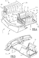
- Figure 5 is a further perspective view of the obstacle deflector 12 of figure 4 with its sub-assembly 17 in the extended position; while figure 6 is a perspective view of the obstacle deflector 12 of figure 4 with its sub-assembly 17 in the retracted position.
- Figure 7 is a perspective view of an alternative embodiment of the obstacle deflector 12 of the present invention which includes two lateral rods 24 and a supporting member or box 26 arranged to host said rods 24.
- Two energy absorber elements 22 are distributed on either sides of a central longitudinal axis X14 or carbodyshell 14. For the sake of simplicity energy absorber elements 22 are not represented on figures 8 and 9 .
- tearing elements 21 are screws or bolts.
- the shield element 20 is fixed to a front end 24a of the rods 24.
- the rods 24 are arranged to slide between the extended position, wherein the shield element 20 is spaced from a distal end 26b of the supporting member 26 and is arranged to push away obstacles placed in front of the train 10, and the retracted position, wherein the shield element 20 is in contact with such distal end 26b of the supporting member 26.
- Figure 8 is a further perspective view of the obstacle deflector 12 of figure 7 with its sub-assembly 17 in the extended position
- figure 9 is a perspective view of the obstacle deflector 12 of figure 7 with its sub-assembly 17 in the retracted position.
- the obstacle deflector 12 comprises also an anticlimber known per se, in order to avoid to slide vertically when compressed to the retracted position and to remain in a horizontal position.
- the tearing elements 21 break and the sub-assembly 17 moves from the extended position to the retracted position.
- the tearing elements 21 such as the above cited bolts or screws are common elements which shall break in a controlled manner.
- the tearing elements 21 have to break at the predefined impact force level threshold.
- the threshold of the impact force is higher than the level of forces occurring during one impact against a big obstacle, and therefore higher than the requirements provided by the fourth scenario of the EN15227 standard.
- the obstacle deflector 12 can remain in its retracted position without losing its functionality while, in an alternative embodiment, it is locked in the retracted position so as not to slide, but after a crash this should not be a real problem anymore.
Landscapes
- Engineering & Computer Science (AREA)
- Mechanical Engineering (AREA)
- Vibration Dampers (AREA)
Abstract
Description
- The present invention relates to an obstacle deflector for a rail vehicle.
- An obstacle deflector for a rail vehicle, also known as snowplough or pilot, is a device which is usually placed at the front end of a carbodyshell of a rail vehicle, such as a train, and is arranged to deflect possible obstacles present on the railway track that might otherwise derail the train when the latter is travelling along the track. Obstacles should be deflected as early as possible because otherwise they might damage the train, thus resulting in unnecessary maintenance costs.
-
Figure 1 shows a schematic lateral view of a train 1 having an obstacle deflector 2 which is fixed to the front end of its carbodyshell 4 and is capable of performing the primary task of removing obstacles from the railway track, thus protecting the train 1 from derailment. However, this obstacle deflector 2 is not capable of protecting the carbodyshell 4 from damages, because it happens quite frequently that obstacles firstly hit the cover panel of the carbodyshell 4 and only later they are pushed away by the obstacle deflector 2. - In fact, an obstacle deflector designed according to the EN 15227 standard has usually to be installed in longitudinal direction behind or in a back position below the energy absorber elements, also known as energy dissipation devices, which are fixed, in known manner, to the front end of the carbodyshell 4 and are arranged to absorb the impact energy in case of impacts with obstacles which may be present on the path of the train 1.
- In order to guarantee the proper functioning of these energy absorber elements, the obstacle deflector 2 is usually placed behind them because otherwise, due to the fact that it is a fixed element, in case of crash events it would restrain the energy absorber elements, not allowing their proper functioning.
- As a result, the front end of the carbodyshell of the train 1, with its grp (glass reinforced plastic) structure and equipment, remains unprotected.
- It is therefore an object of the present invention to provide an obstacle deflector for a rail vehicle which is capable of both removing obstacles from the railway track and protecting the carbodyshell of the train from impacts with these obstacles, thus overcoming the limitations of the prior art solutions.
- This and other objects are fully achieved by virtue of an obstacle deflector for a rail vehicle having the characteristics defined in independent claim 1.
- Preferred embodiments of the invention are specified in the dependent claims, whose subject-matter is to be understood as forming an integral part of the present description.
- Further characteristics and advantages of the present invention will become apparent from the following description, provided merely by way of a non-limiting example, with reference to the enclosed drawings, in which:
-
Figure 1 shows a schematic lateral view of a train having an obstacle deflector according to the prior art; -
Figure 2 shows a schematic lateral view of a train having an obstacle deflector according to the present invention; -
Figure 3 shows a lateral view of the train offigure 2 with its obstacle deflector; -
Figure 4 shows a perspective view of an obstacle deflector according to the present invention; -
Figure 5 shows a perspective view of the obstacle deflector offigure 4 in an extended position, when seen in a direction different from the one offigure 4 ; -
Figure 6 shows a perspective view of the obstacle deflector offigure 5 in a retracted position, when seen in the same direction as infigure 4 ; -
Figure 7 shows a perspective view of an alternative embodiment of the obstacle deflector according to the present invention; -
Figure 8 shows a perspective view of the obstacle deflector offigure 7 in an extended position, when seen in a direction different from the one offigure 7 ; and -
Figure 9 shows a perspective view of the obstacle deflector offigure 8 in a retracted position, when seen in the same direction as infigure 7 . - Briefly, the obstacle deflector of the present invention is capable of both removing obstacles present on a railway track and protecting the carbodyshell of a train without requiring modifications to the energy absorber elements usually present on the front end of a carbodyshell of a train.
- The obstacle deflector of the present invention, thanks to the fact that of being movable, can be placed in front of the energy absorbers because during a crash scenario it is arranged to slide back without affecting the operation of the energy absorbers.
- The obstacle deflector according to the present invention has the same functionalities as any other fixed mounted deflector of the prior art according to the EN 15227 standard.
-
Figure 2 shows a schematic lateral view of atrain 10 having anobstacle deflector 12 fixed to the front end of itscarbodyshell 14 in a forward position with respect to the prior art, so that obstacles first collide with theobstacle deflector 12 and then are moved away from the railway track. - The
obstacle deflector 12 is mounted in an extended position so as to project forward beyond energy absorber elements of the train 10: when an obstacle approaches thetrain 10, it firstly impacts theobstacle deflector 12. - If the level of the impact force between the obstacle and the
obstacle deflector 12 itself is below a predetermined threshold, theobstacle deflector 12 pushes the obstacle away from the railway track, otherwise, it moves to a retracted position wherein it does no more project beyond the energy absorber elements. -
Figure 3 shows a lateral view of thetrain 10 with itsobstacle deflector 12 placed underenergy absorber elements 22, and another opposed train 10' with its obstacle deflector 12' placed under its energy absorber elements 22'. - In case of crash between the two
trains 10 and 10', therespective obstacle deflectors 12 and 12' move from the extended position shown infigure 3 , wherein they project beyond the correspondingenergy absorber elements 22 an 22', to the retracted position, wherein they do not project beyond the correspondingenergy absorber elements 22 an 22', as disclosed herein below in detail. - In order to withstand accidents with obstacles having an impact force level below a threshold, for example equal to 300kN, as indicated in the scenarios disclosed in the EN 15227 standard, the
obstacle deflector 12 is positioned, as above indicated, so as to project beyond the energy absorberelements 22, while having at the same time the stability and stiffness required by EN 15227 standard. Theobstacle deflector 12 is however able to move backwards to the retracted position if the impact force level exceeds said threshold. - With reference to
figure 4 theobstacle deflector 12 of the present invention includes asupport member 18 having a buckling-free system, for example a sledge 16 (e.g. a Coradia LINT, a light regional train of Alstom TD), and ashield element 20 fixed to afront end 16a of thesledge 16. Thesledge 16 is carried by thesupport member 18 so as to be slideably movable with respect to thesupport member 18 between a first position represented onfigures 4 and 5 , the above-cited extended position, and a second position represented onfigure 6 , the above-cited retracted position. Thesledge 16 and theshield 20 together form asub-assembly 17, movable with respect to supportmember 18. - The
support member 18 is arranged to be fixed at aproximal end 18a to a front end of thecarbodyshell 14 of thetrain 10. - The
sledge 16 is arranged to slide between the extended position, wherein theshield element 20 is spaced from adistal end 18b of thesupport member 18 and is arranged to push away obstacles placed in front of thetrain 10, and the retracted position, wherein theshield element 20 is in contact with suchdistal end 18b of thesupport member 18. - In case of a crash force exceeding the threshold, the
sub-assembly 17, and thus thesledge 16, can slide into the lower area of the grp part of thecarbodyshell 14, thus moving from the extended position to the retracted position. - In order to allow this sliding movement of the
sub-assembly 17, thesledge 16 and thesupport member 18 are connected bytearing elements 21, such as breakable screws, one of which is represented in an exploded position onfigure 5 . This allowssledge 16 to slide with respect to supportmember 18, from the extended position offigures 4 and 5 , to the retracted position offigure 6 , when thetearing elements 21 are broken due to an impact force of an obstacle on theshield element 20 exceeding the threshold of the impact force. - Two energy absorber
elements 22, placed side by side above theobstacle deflector 12, are arranged to be fixed at aproximal end 22a to thecarbodyshell 14 of thetrain 10 without being in contact with theobstacle deflector 12, and theshield element 20 is mounted so that, in the extended position, it project forwards beyonddistal ends 22b of theenergy absorber elements 22. In the retracted position, theshield element 20 does not project anymore beyond thedistal end 22b of theenergy absorber elements 22, so that it does not interfere with an obstacle if this obstacle interacts with theenergy absorber elements 22. -
Energy absorber elements 22 are distributed on either sides of a central longitudinal axis X14 ofcarbodyshell 14. For the sake of simplicityenergy absorber elements 22 are not represented onfigures 5 and6 . -
Figure 5 is a further perspective view of theobstacle deflector 12 offigure 4 with itssub-assembly 17 in the extended position; whilefigure 6 is a perspective view of theobstacle deflector 12 offigure 4 with itssub-assembly 17 in the retracted position. -
Figure 7 is a perspective view of an alternative embodiment of theobstacle deflector 12 of the present invention which includes twolateral rods 24 and a supporting member orbox 26 arranged to host saidrods 24. Twoenergy absorber elements 22 are distributed on either sides of a central longitudinal axis X14 orcarbodyshell 14. For the sake of simplicityenergy absorber elements 22 are not represented onfigures 8 and 9 . - The
shield element 20 and therods 24 together form asub-assembly 17, movable with respect to supportmember 18. Preferably,tearing elements 21 are screws or bolts. - The
shield element 20 is fixed to afront end 24a of therods 24. - The
rods 24 are arranged to slide between the extended position, wherein theshield element 20 is spaced from adistal end 26b of the supportingmember 26 and is arranged to push away obstacles placed in front of thetrain 10, and the retracted position, wherein theshield element 20 is in contact with suchdistal end 26b of the supportingmember 26. -
Figure 8 is a further perspective view of theobstacle deflector 12 offigure 7 with itssub-assembly 17 in the extended position, whilefigure 9 is a perspective view of theobstacle deflector 12 offigure 7 with itssub-assembly 17 in the retracted position. - Advantageously, in one embodiment and/or the other, the
obstacle deflector 12 comprises also an anticlimber known per se, in order to avoid to slide vertically when compressed to the retracted position and to remain in a horizontal position. - In all embodiments, when the impact force level exceeds the above cited threshold, the
tearing elements 21 break and thesub-assembly 17 moves from the extended position to the retracted position. - The
tearing elements 21 such as the above cited bolts or screws are common elements which shall break in a controlled manner. In particular, thetearing elements 21 have to break at the predefined impact force level threshold. - Preferably, the threshold of the impact force is higher than the level of forces occurring during one impact against a big obstacle, and therefore higher than the requirements provided by the fourth scenario of the EN15227 standard.
- The
obstacle deflector 12 can remain in its retracted position without losing its functionality while, in an alternative embodiment, it is locked in the retracted position so as not to slide, but after a crash this should not be a real problem anymore. - Clearly, the principle of the invention remaining the same, the embodiments and the details of production can be varied considerably from what has been described and illustrated purely by way of non-limiting example, without departing from the scope of protection of the present invention as defined by the attached claims.
Claims (8)
- Obstacle deflector (12) for a rail vehicle (10) having a carbodyshell (14) with a front end, the obstacle deflector (12) comprising:- a support member (18, 26) arranged to be fixed at a proximate end (18a) to the a front end of the carbodyshell (14);- a moving element (16, 24) supported by said support member (18, 26) so as to be slideably movable with respect to the support member (18, 26);- a shield element (20) fixed to a front end (16a, 24a) the moving element (16, 24); wherein the moving element (16, 24) is arranged to move between:- an extended position, wherein the shield element (20) is spaced from a distal end (18b, 26b) of the support member (18, 26) and is arranged to push away an obstacle placed in front of the rail vehicle (10); and- a retracted position, wherein the shield element (20) is in contact with the distal end (18b, 26b) of the support member (18) and is arranged not to push away said obstacle.
- The obstacle deflector (12) of claim 1, wherein:in the extended position, the shield element (20) is arranged to project forward beyond a distal end (22b) of energy absorber elements (22) fixed to the front end of the carbodyshell (14); andin the retracted position, the shield element (20) is arranged not to project beyond the distal end (22b) of the energy absorber elements (22).
- The obstacle deflector (12) of claim 1 or 2, wherein the moving element (16, 24) is arranged to move from the extended position to the retracted position when the force of an impact between an obstacle and the shield element (20) exceeds a predetermined threshold.
- The obstacle deflector (12) of claim 2, wherein one of said energy absorber elements (22) is placed on the moving element (16, 24) between two portions (19) of the support member (18).
- The obstacle deflector (12) of any of the preceding claims, wherein the moving element is a sledge (16).
- The obstacle deflector (12) of any of the preceding claims, wherein the moving element is formed by two lateral rods (24).
- The obstacle deflector (12) of claim 6, wherein the support member (26) is a supporting box (26) arranged to host said lateral rods (24).
- The obstacle deflector (12) of any of the preceding claims, wherein the moving element (16, 24) and the shield element (20) together form a sub-assembly (17) movable with respect to the support member (18, 26).
Priority Applications (2)
| Application Number | Priority Date | Filing Date | Title |
|---|---|---|---|
| PL18305679T PL3575178T3 (en) | 2018-06-01 | 2018-06-01 | Obstacle deflector for a rail vehicle |
| EP18305679.5A EP3575178B1 (en) | 2018-06-01 | 2018-06-01 | Obstacle deflector for a rail vehicle |
Applications Claiming Priority (1)
| Application Number | Priority Date | Filing Date | Title |
|---|---|---|---|
| EP18305679.5A EP3575178B1 (en) | 2018-06-01 | 2018-06-01 | Obstacle deflector for a rail vehicle |
Publications (2)
| Publication Number | Publication Date |
|---|---|
| EP3575178A1 true EP3575178A1 (en) | 2019-12-04 |
| EP3575178B1 EP3575178B1 (en) | 2021-08-04 |
Family
ID=62567576
Family Applications (1)
| Application Number | Title | Priority Date | Filing Date |
|---|---|---|---|
| EP18305679.5A Active EP3575178B1 (en) | 2018-06-01 | 2018-06-01 | Obstacle deflector for a rail vehicle |
Country Status (2)
| Country | Link |
|---|---|
| EP (1) | EP3575178B1 (en) |
| PL (1) | PL3575178T3 (en) |
Cited By (1)
| Publication number | Priority date | Publication date | Assignee | Title |
|---|---|---|---|---|
| EP4464569A1 (en) | 2023-05-16 | 2024-11-20 | ALSTOM Holdings | Rail sweeper for a rail vehicle and rail vehicle comprising said rail sweeper |
Citations (5)
| Publication number | Priority date | Publication date | Assignee | Title |
|---|---|---|---|---|
| DE121726C (en) * | ||||
| DE166218C (en) * | 1904-02-14 | 1905-12-11 | Ludwig Quolilin | TRAM PROTECTION DEVICE THAT CAN BE RELEASED BY THE OBSTACLE, BY ENEN PRESS PISTON |
| FR467678A (en) * | 1914-01-24 | 1914-06-17 | John Henry Ferguson | Improvements to body-picking baskets |
| US3848914A (en) * | 1971-12-15 | 1974-11-19 | Sperry Rand Corp | Motor shiftable shock absorbing bumper |
| DE102015205283A1 (en) * | 2015-03-24 | 2016-09-29 | Bombardier Transportation Gmbh | Front arrangement of a rail vehicle and method for operating and producing the rail vehicle |
-
2018
- 2018-06-01 PL PL18305679T patent/PL3575178T3/en unknown
- 2018-06-01 EP EP18305679.5A patent/EP3575178B1/en active Active
Patent Citations (5)
| Publication number | Priority date | Publication date | Assignee | Title |
|---|---|---|---|---|
| DE121726C (en) * | ||||
| DE166218C (en) * | 1904-02-14 | 1905-12-11 | Ludwig Quolilin | TRAM PROTECTION DEVICE THAT CAN BE RELEASED BY THE OBSTACLE, BY ENEN PRESS PISTON |
| FR467678A (en) * | 1914-01-24 | 1914-06-17 | John Henry Ferguson | Improvements to body-picking baskets |
| US3848914A (en) * | 1971-12-15 | 1974-11-19 | Sperry Rand Corp | Motor shiftable shock absorbing bumper |
| DE102015205283A1 (en) * | 2015-03-24 | 2016-09-29 | Bombardier Transportation Gmbh | Front arrangement of a rail vehicle and method for operating and producing the rail vehicle |
Cited By (1)
| Publication number | Priority date | Publication date | Assignee | Title |
|---|---|---|---|---|
| EP4464569A1 (en) | 2023-05-16 | 2024-11-20 | ALSTOM Holdings | Rail sweeper for a rail vehicle and rail vehicle comprising said rail sweeper |
Also Published As
| Publication number | Publication date |
|---|---|
| PL3575178T3 (en) | 2022-01-10 |
| EP3575178B1 (en) | 2021-08-04 |
Similar Documents
| Publication | Publication Date | Title |
|---|---|---|
| KR101053878B1 (en) | Road Shock Absorber | |
| US10518789B2 (en) | Coupling assembly and rail vehicle having same | |
| TWI515135B (en) | Chassis and vehicle having the same | |
| US20080250965A1 (en) | Rail car collision system | |
| EP3575178B1 (en) | Obstacle deflector for a rail vehicle | |
| KR20150145367A (en) | Bumper stiffener apparatus for vehicle | |
| KR20150111765A (en) | Vehicle impact absorb device for crash barrier | |
| US9611601B1 (en) | Crash absorbing guardrail panel assembly | |
| RU2668011C1 (en) | Railway transport, in particular, locomotive | |
| US9802628B2 (en) | Anti-climbing protection apparatus for a rail vehicle | |
| KR20160030670A (en) | Shock-absorbing apparatus for guard rail end | |
| US7946745B2 (en) | System for mounting a headlight on a motor vehicle and a motor vehicle comprising such a system | |
| KR101644909B1 (en) | Vehicle impact absorb device for crash barrier | |
| EP3660219B1 (en) | End terminal for a safety guardrail | |
| KR20160004718A (en) | Shock-absorbing apparatus for guard rail end | |
| EP4464569A1 (en) | Rail sweeper for a rail vehicle and rail vehicle comprising said rail sweeper | |
| KR101447906B1 (en) | Shock reliever for road | |
| KR100556234B1 (en) | Vehicle shock absorbing device installed inside the tunnel | |
| KR101773835B1 (en) | Shock-absorbing apparatus for guard rail end | |
| KR100889943B1 (en) | Shock Absorption Facility Using Cutting Energy | |
| KR101535235B1 (en) | Guard rails taht can be a shock absorption through the plastic doformation and elasic doformation | |
| KR101351445B1 (en) | a buffer for collision | |
| AR109956A1 (en) | COUPLER AND RAILWAY VEHICLE ASSEMBLY THAT HAS IT | |
| KR200350738Y1 (en) | Shock absorption apparatus of vehicle for tunnel | |
| KR20160029447A (en) | Support reinforcing apparatus for guardrail post |
Legal Events
| Date | Code | Title | Description |
|---|---|---|---|
| PUAI | Public reference made under article 153(3) epc to a published international application that has entered the european phase |
Free format text: ORIGINAL CODE: 0009012 |
|
| STAA | Information on the status of an ep patent application or granted ep patent |
Free format text: STATUS: THE APPLICATION HAS BEEN PUBLISHED |
|
| STAA | Information on the status of an ep patent application or granted ep patent |
Free format text: STATUS: REQUEST FOR EXAMINATION WAS MADE |
|
| AK | Designated contracting states |
Kind code of ref document: A1 Designated state(s): AL AT BE BG CH CY CZ DE DK EE ES FI FR GB GR HR HU IE IS IT LI LT LU LV MC MK MT NL NO PL PT RO RS SE SI SK SM TR |
|
| AX | Request for extension of the european patent |
Extension state: BA ME |
|
| 17P | Request for examination filed |
Effective date: 20191119 |
|
| RBV | Designated contracting states (corrected) |
Designated state(s): AL AT BE BG CH CY CZ DE DK EE ES FI FR GB GR HR HU IE IS IT LI LT LU LV MC MK MT NL NO PL PT RO RS SE SI SK SM TR |
|
| STAA | Information on the status of an ep patent application or granted ep patent |
Free format text: STATUS: EXAMINATION IS IN PROGRESS |
|
| 17Q | First examination report despatched |
Effective date: 20200714 |
|
| GRAP | Despatch of communication of intention to grant a patent |
Free format text: ORIGINAL CODE: EPIDOSNIGR1 |
|
| STAA | Information on the status of an ep patent application or granted ep patent |
Free format text: STATUS: GRANT OF PATENT IS INTENDED |
|
| INTG | Intention to grant announced |
Effective date: 20210331 |
|
| GRAS | Grant fee paid |
Free format text: ORIGINAL CODE: EPIDOSNIGR3 |
|
| GRAA | (expected) grant |
Free format text: ORIGINAL CODE: 0009210 |
|
| STAA | Information on the status of an ep patent application or granted ep patent |
Free format text: STATUS: THE PATENT HAS BEEN GRANTED |
|
| AK | Designated contracting states |
Kind code of ref document: B1 Designated state(s): AL AT BE BG CH CY CZ DE DK EE ES FI FR GB GR HR HU IE IS IT LI LT LU LV MC MK MT NL NO PL PT RO RS SE SI SK SM TR |
|
| REG | Reference to a national code |
Ref country code: GB Ref legal event code: FG4D |
|
| REG | Reference to a national code |
Ref country code: AT Ref legal event code: REF Ref document number: 1416704 Country of ref document: AT Kind code of ref document: T Effective date: 20210815 |
|
| REG | Reference to a national code |
Ref country code: CH Ref legal event code: EP |
|
| REG | Reference to a national code |
Ref country code: DE Ref legal event code: R096 Ref document number: 602018021157 Country of ref document: DE |
|
| REG | Reference to a national code |
Ref country code: IE Ref legal event code: FG4D |
|
| REG | Reference to a national code |
Ref country code: LT Ref legal event code: MG9D |
|
| REG | Reference to a national code |
Ref country code: NL Ref legal event code: MP Effective date: 20210804 |
|
| REG | Reference to a national code |
Ref country code: AT Ref legal event code: MK05 Ref document number: 1416704 Country of ref document: AT Kind code of ref document: T Effective date: 20210804 |
|
| PG25 | Lapsed in a contracting state [announced via postgrant information from national office to epo] |
Ref country code: LT Free format text: LAPSE BECAUSE OF FAILURE TO SUBMIT A TRANSLATION OF THE DESCRIPTION OR TO PAY THE FEE WITHIN THE PRESCRIBED TIME-LIMIT Effective date: 20210804 Ref country code: AT Free format text: LAPSE BECAUSE OF FAILURE TO SUBMIT A TRANSLATION OF THE DESCRIPTION OR TO PAY THE FEE WITHIN THE PRESCRIBED TIME-LIMIT Effective date: 20210804 Ref country code: BG Free format text: LAPSE BECAUSE OF FAILURE TO SUBMIT A TRANSLATION OF THE DESCRIPTION OR TO PAY THE FEE WITHIN THE PRESCRIBED TIME-LIMIT Effective date: 20211104 Ref country code: NO Free format text: LAPSE BECAUSE OF FAILURE TO SUBMIT A TRANSLATION OF THE DESCRIPTION OR TO PAY THE FEE WITHIN THE PRESCRIBED TIME-LIMIT Effective date: 20211104 Ref country code: PT Free format text: LAPSE BECAUSE OF FAILURE TO SUBMIT A TRANSLATION OF THE DESCRIPTION OR TO PAY THE FEE WITHIN THE PRESCRIBED TIME-LIMIT Effective date: 20211206 Ref country code: ES Free format text: LAPSE BECAUSE OF FAILURE TO SUBMIT A TRANSLATION OF THE DESCRIPTION OR TO PAY THE FEE WITHIN THE PRESCRIBED TIME-LIMIT Effective date: 20210804 Ref country code: FI Free format text: LAPSE BECAUSE OF FAILURE TO SUBMIT A TRANSLATION OF THE DESCRIPTION OR TO PAY THE FEE WITHIN THE PRESCRIBED TIME-LIMIT Effective date: 20210804 Ref country code: HR Free format text: LAPSE BECAUSE OF FAILURE TO SUBMIT A TRANSLATION OF THE DESCRIPTION OR TO PAY THE FEE WITHIN THE PRESCRIBED TIME-LIMIT Effective date: 20210804 Ref country code: SE Free format text: LAPSE BECAUSE OF FAILURE TO SUBMIT A TRANSLATION OF THE DESCRIPTION OR TO PAY THE FEE WITHIN THE PRESCRIBED TIME-LIMIT Effective date: 20210804 Ref country code: RS Free format text: LAPSE BECAUSE OF FAILURE TO SUBMIT A TRANSLATION OF THE DESCRIPTION OR TO PAY THE FEE WITHIN THE PRESCRIBED TIME-LIMIT Effective date: 20210804 |
|
| PG25 | Lapsed in a contracting state [announced via postgrant information from national office to epo] |
Ref country code: LV Free format text: LAPSE BECAUSE OF FAILURE TO SUBMIT A TRANSLATION OF THE DESCRIPTION OR TO PAY THE FEE WITHIN THE PRESCRIBED TIME-LIMIT Effective date: 20210804 Ref country code: GR Free format text: LAPSE BECAUSE OF FAILURE TO SUBMIT A TRANSLATION OF THE DESCRIPTION OR TO PAY THE FEE WITHIN THE PRESCRIBED TIME-LIMIT Effective date: 20211105 |
|
| PG25 | Lapsed in a contracting state [announced via postgrant information from national office to epo] |
Ref country code: NL Free format text: LAPSE BECAUSE OF FAILURE TO SUBMIT A TRANSLATION OF THE DESCRIPTION OR TO PAY THE FEE WITHIN THE PRESCRIBED TIME-LIMIT Effective date: 20210804 |
|
| PG25 | Lapsed in a contracting state [announced via postgrant information from national office to epo] |
Ref country code: DK Free format text: LAPSE BECAUSE OF FAILURE TO SUBMIT A TRANSLATION OF THE DESCRIPTION OR TO PAY THE FEE WITHIN THE PRESCRIBED TIME-LIMIT Effective date: 20210804 |
|
| REG | Reference to a national code |
Ref country code: DE Ref legal event code: R097 Ref document number: 602018021157 Country of ref document: DE |
|
| PG25 | Lapsed in a contracting state [announced via postgrant information from national office to epo] |
Ref country code: SM Free format text: LAPSE BECAUSE OF FAILURE TO SUBMIT A TRANSLATION OF THE DESCRIPTION OR TO PAY THE FEE WITHIN THE PRESCRIBED TIME-LIMIT Effective date: 20210804 Ref country code: SK Free format text: LAPSE BECAUSE OF FAILURE TO SUBMIT A TRANSLATION OF THE DESCRIPTION OR TO PAY THE FEE WITHIN THE PRESCRIBED TIME-LIMIT Effective date: 20210804 Ref country code: RO Free format text: LAPSE BECAUSE OF FAILURE TO SUBMIT A TRANSLATION OF THE DESCRIPTION OR TO PAY THE FEE WITHIN THE PRESCRIBED TIME-LIMIT Effective date: 20210804 Ref country code: EE Free format text: LAPSE BECAUSE OF FAILURE TO SUBMIT A TRANSLATION OF THE DESCRIPTION OR TO PAY THE FEE WITHIN THE PRESCRIBED TIME-LIMIT Effective date: 20210804 Ref country code: CZ Free format text: LAPSE BECAUSE OF FAILURE TO SUBMIT A TRANSLATION OF THE DESCRIPTION OR TO PAY THE FEE WITHIN THE PRESCRIBED TIME-LIMIT Effective date: 20210804 Ref country code: AL Free format text: LAPSE BECAUSE OF FAILURE TO SUBMIT A TRANSLATION OF THE DESCRIPTION OR TO PAY THE FEE WITHIN THE PRESCRIBED TIME-LIMIT Effective date: 20210804 |
|
| PLBE | No opposition filed within time limit |
Free format text: ORIGINAL CODE: 0009261 |
|
| STAA | Information on the status of an ep patent application or granted ep patent |
Free format text: STATUS: NO OPPOSITION FILED WITHIN TIME LIMIT |
|
| 26N | No opposition filed |
Effective date: 20220506 |
|
| PG25 | Lapsed in a contracting state [announced via postgrant information from national office to epo] |
Ref country code: IT Free format text: LAPSE BECAUSE OF FAILURE TO SUBMIT A TRANSLATION OF THE DESCRIPTION OR TO PAY THE FEE WITHIN THE PRESCRIBED TIME-LIMIT Effective date: 20210804 |
|
| PG25 | Lapsed in a contracting state [announced via postgrant information from national office to epo] |
Ref country code: SI Free format text: LAPSE BECAUSE OF FAILURE TO SUBMIT A TRANSLATION OF THE DESCRIPTION OR TO PAY THE FEE WITHIN THE PRESCRIBED TIME-LIMIT Effective date: 20210804 |
|
| PG25 | Lapsed in a contracting state [announced via postgrant information from national office to epo] |
Ref country code: MC Free format text: LAPSE BECAUSE OF FAILURE TO SUBMIT A TRANSLATION OF THE DESCRIPTION OR TO PAY THE FEE WITHIN THE PRESCRIBED TIME-LIMIT Effective date: 20210804 |
|
| REG | Reference to a national code |
Ref country code: CH Ref legal event code: PL |
|
| REG | Reference to a national code |
Ref country code: BE Ref legal event code: MM Effective date: 20220630 |
|
| GBPC | Gb: european patent ceased through non-payment of renewal fee |
Effective date: 20220601 |
|
| PG25 | Lapsed in a contracting state [announced via postgrant information from national office to epo] |
Ref country code: LU Free format text: LAPSE BECAUSE OF NON-PAYMENT OF DUE FEES Effective date: 20220601 Ref country code: LI Free format text: LAPSE BECAUSE OF NON-PAYMENT OF DUE FEES Effective date: 20220630 Ref country code: IE Free format text: LAPSE BECAUSE OF NON-PAYMENT OF DUE FEES Effective date: 20220601 Ref country code: CH Free format text: LAPSE BECAUSE OF NON-PAYMENT OF DUE FEES Effective date: 20220630 |
|
| PG25 | Lapsed in a contracting state [announced via postgrant information from national office to epo] |
Ref country code: GB Free format text: LAPSE BECAUSE OF NON-PAYMENT OF DUE FEES Effective date: 20220601 Ref country code: BE Free format text: LAPSE BECAUSE OF NON-PAYMENT OF DUE FEES Effective date: 20220630 |
|
| P01 | Opt-out of the competence of the unified patent court (upc) registered |
Effective date: 20230823 |
|
| PG25 | Lapsed in a contracting state [announced via postgrant information from national office to epo] |
Ref country code: HU Free format text: LAPSE BECAUSE OF FAILURE TO SUBMIT A TRANSLATION OF THE DESCRIPTION OR TO PAY THE FEE WITHIN THE PRESCRIBED TIME-LIMIT; INVALID AB INITIO Effective date: 20180601 |
|
| PG25 | Lapsed in a contracting state [announced via postgrant information from national office to epo] |
Ref country code: MK Free format text: LAPSE BECAUSE OF FAILURE TO SUBMIT A TRANSLATION OF THE DESCRIPTION OR TO PAY THE FEE WITHIN THE PRESCRIBED TIME-LIMIT Effective date: 20210804 Ref country code: CY Free format text: LAPSE BECAUSE OF FAILURE TO SUBMIT A TRANSLATION OF THE DESCRIPTION OR TO PAY THE FEE WITHIN THE PRESCRIBED TIME-LIMIT Effective date: 20210804 |
|
| PG25 | Lapsed in a contracting state [announced via postgrant information from national office to epo] |
Ref country code: TR Free format text: LAPSE BECAUSE OF FAILURE TO SUBMIT A TRANSLATION OF THE DESCRIPTION OR TO PAY THE FEE WITHIN THE PRESCRIBED TIME-LIMIT Effective date: 20210804 |
|
| PG25 | Lapsed in a contracting state [announced via postgrant information from national office to epo] |
Ref country code: MT Free format text: LAPSE BECAUSE OF FAILURE TO SUBMIT A TRANSLATION OF THE DESCRIPTION OR TO PAY THE FEE WITHIN THE PRESCRIBED TIME-LIMIT Effective date: 20210804 |
|
| PGFP | Annual fee paid to national office [announced via postgrant information from national office to epo] |
Ref country code: DE Payment date: 20250618 Year of fee payment: 8 Ref country code: PL Payment date: 20250522 Year of fee payment: 8 |
|
| PGFP | Annual fee paid to national office [announced via postgrant information from national office to epo] |
Ref country code: FR Payment date: 20250625 Year of fee payment: 8 |