EP3575154A1 - Interior construction device - Google Patents
Interior construction device Download PDFInfo
- Publication number
- EP3575154A1 EP3575154A1 EP19176087.5A EP19176087A EP3575154A1 EP 3575154 A1 EP3575154 A1 EP 3575154A1 EP 19176087 A EP19176087 A EP 19176087A EP 3575154 A1 EP3575154 A1 EP 3575154A1
- Authority
- EP
- European Patent Office
- Prior art keywords
- door
- unit
- interior
- fitting device
- interior fitting
- Prior art date
- Legal status (The legal status is an assumption and is not a legal conclusion. Google has not performed a legal analysis and makes no representation as to the accuracy of the status listed.)
- Granted
Links
- 238000010276 construction Methods 0.000 title claims description 13
- 238000000034 method Methods 0.000 claims description 32
- 238000006073 displacement reaction Methods 0.000 claims description 7
- 230000008878 coupling Effects 0.000 description 28
- 238000010168 coupling process Methods 0.000 description 28
- 238000005859 coupling reaction Methods 0.000 description 28
- 238000000926 separation method Methods 0.000 description 10
- 230000007246 mechanism Effects 0.000 description 8
- 230000001419 dependent effect Effects 0.000 description 4
- 239000000463 material Substances 0.000 description 3
- 239000002184 metal Substances 0.000 description 3
- 239000002023 wood Substances 0.000 description 3
- 239000011111 cardboard Substances 0.000 description 2
- 238000006243 chemical reaction Methods 0.000 description 2
- 239000011521 glass Substances 0.000 description 2
- 239000000123 paper Substances 0.000 description 2
- 239000004033 plastic Substances 0.000 description 2
- 239000000725 suspension Substances 0.000 description 2
- 239000004753 textile Substances 0.000 description 2
- 230000001960 triggered effect Effects 0.000 description 2
- 230000000694 effects Effects 0.000 description 1
- 239000012535 impurity Substances 0.000 description 1
- 238000009434 installation Methods 0.000 description 1
- 238000004519 manufacturing process Methods 0.000 description 1
- 238000012986 modification Methods 0.000 description 1
- 230000004048 modification Effects 0.000 description 1
- 238000005406 washing Methods 0.000 description 1
Images


Classifications
-
- B—PERFORMING OPERATIONS; TRANSPORTING
- B60—VEHICLES IN GENERAL
- B60R—VEHICLES, VEHICLE FITTINGS, OR VEHICLE PARTS, NOT OTHERWISE PROVIDED FOR
- B60R15/00—Arrangements or adaptations of sanitation devices
Definitions
- the invention relates to an interior fitting device according to the preamble of claim 1, and a method according to the preamble of claim 19.
- An interior fitting device having at least one door unit, which comprises at least one first door element and at least one second door element, has already been proposed.
- the object of the invention is in particular to provide a generic device with improved properties in terms of flexibility, in particular with respect to a room layout.
- the object is achieved by the features of claim 1, while advantageous embodiments and modifications of the invention can be taken from the dependent claims.
- the invention is based on an interior fitting device for a motor vehicle, which is optionally provided for at least partially separating a first space area and a second space area of the vehicle, with at least one movable door unit, which is movable from at least one first door position in at least one second door position and which has at least one first door element and at least one second door element which is at least indirectly coupled to the first door element.
- the second door member in the first door position, is immovably fixed relative to the first door member and in the second door position, the second door member is movable relative to the first door member.
- a flexibility of a room layout can be improved.
- a User comfort especially in terms of a sense of space can be achieved, as is the case for example with a hotel suite.
- both a particularly advantageous accessibility and a separation of spatial areas can be achieved with each other.
- a particularly compact arrangement can be provided and thus a space can be reduced.
- An "interior fitting device” for a caravan is to be understood in particular to mean a device which is provided for interior fitting of a caravan.
- the interior fitting device is in particular a functional component, in particular a construction and / or functional component, of an interior construction.
- the interior construction device can form an interior construction at least partially, preferably at least to a large extent and particularly preferably completely.
- provided is intended to be understood in particular specially programmed, designed and / or equipped.
- the fact that an object is intended for a specific function should in particular mean that the object fulfills and / or executes this specific function in at least one application and / or operating state.
- a “caravan” is to be understood in particular a motorhome, a caravan and / or a van.
- a "room area” is to be understood in particular as meaning a sanitary area, in particular a shower area and / or washing area, a sleeping area, a living area, a kitchen area and / or a dining area.
- the first room area is a sanitary area.
- the sanitary area advantageously comprises at least one toilet and / or a washbasin.
- the second room area is a sleeping area and comprises at least one bed, preferably a double bed.
- An "at least partial separation" of a first spatial region and a second spatial region should in particular be understood to mean that a passage between at least the first spatial region and the second spatial region forms at least partially, preferably at least to a large extent and particularly preferably completely.
- the interior fitting device is provided for at least a majority, and particularly preferably complete, optional separation of the spatial area.
- Under a "door unit” should in this Connection should be understood in particular a unit which is provided for an optional at least partially closing or opening of at least one passage between at least two separable space regions.
- the door unit preferably comprises at least two, preferably at least three and particularly preferably a plurality of door elements.
- the door unit comprises at most three and preferably at most two door elements.
- the door unit comprises exactly two door elements.
- a "door element” is to be understood in this context, in particular a door leaf, a grid and / or a pleated.
- the door element is at least partially made of wood, a metal sheet, a plastic, glass, paper, cardboard and / or a textile material.
- a base area of the first door element is in particular at least substantially identical to a base area of the second door element.
- at least substantially is to be understood in this context in particular that a deviation from a predetermined value, in particular less than 25%, preferably less than 10% and more preferably less than 5% of the predetermined value deviates.
- a base area of the first door element may be larger and preferably substantially larger than a base area of the second door element.
- substantially greater is meant in particular at least 25%, preferably 35% and more preferably at least 45% greater.
- the first door element and the second door element are preferably arranged relative to each other such that an outer side of the first door element faces the second space area, an inner side of the first door element faces the first space area, an outer side of the second door element faces the first space area, an inner side of the first door element second door member facing the second space portion and / or the inside of the first door member facing the inside of the second door member.
- a door position of the door unit is to be understood in particular as meaning a special position of the door unit.
- two objects are coupled at least indirectly
- the door elements are in particular coupled to one another in a movable manner, at least in a first door position and at least one second door position to be arranged.
- a "door position” is to be understood in particular a special position of a first door element relative to a second door element of the door unit to each other.
- the door unit has at least one coupling unit, in particular for the at least indirect coupling of the first door element and the second door element.
- the coupling unit is at least partially disposed between the first door element and the second door element and preferably at their respective inner sides.
- the coupling unit has, in particular, at least one first coupling element and at least one second coupling element, which corresponds to the first coupling element.
- the first coupling element is arranged in particular on the first door element, in particular its inside.
- the second coupling element is in particular the second door element, in particular the inside, arranged.
- the coupling elements are preferably designed as interlocking pull-out rails, preferably telescopic pull-out rails.
- the coupling unit may have further coupling elements, which are arranged at least between the first and the second coupling element, for example, to telescopically enlarge an extension length of the door elements to each other.
- the door elements are arranged one behind the other and fixed immovably to each other.
- the first door element and the second door element are at least partially shifted from each other.
- the door unit, in particular the second door element preferably forms a sliding door in relation to the first door element. It is also conceivable that the second door element to the first door member could be rotatable and / or pivotable to each other.
- the door unit is provided to release the room areas in the first door position and to at least partially separate the first room area from the second room area in the second door position.
- the door unit In the first door position, the door unit is arranged in particular in a vicinity of an interior wall of the interior fitting device. Preferably, the door unit rests at least indirectly on the interior wall.
- the door unit In the second door position, the door unit is preferably outside the vicinity of the interior wall arranged.
- a "near zone" of an object should in particular be understood as a region which is defined by a maximum distance to this object of at most 30 cm, preferably at most 20 cm and particularly preferably at most 10 cm.
- the door unit can be transferred from the first door position into the second door position by at least one displacement of the door unit in a direction transverse to its main extension plane.
- a "main plane of extension" of an object should be understood in particular to mean a plane which is parallel to a largest side surface of a smallest imaginary cuboid which just completely surrounds the structural unit, and in particular runs through the center of the cuboid.
- transverse it is preferable to mean different from at least substantially parallel.
- "transverse” should be understood to mean at least substantially perpendicular.
- At least substantially parallel should be understood here in particular an alignment of a direction relative to a reference direction, in particular in a plane, wherein the direction and the reference direction an angle of 0 °, in particular taking into account a maximum deviation of less than 8 °, advantageously less than 5 °, and more preferably less than 2 °.
- the term "at least substantially perpendicular” is to be understood here as meaning in particular an alignment of a direction relative to a reference direction, in particular in a plane, the direction and the reference direction being at an angle of 90 °, in particular taking into account a maximum deviation of less than 8 °, advantageously less than 5 °, and more preferably less than 2 °.
- the door unit be oriented from the first door position into the second door position by at least pivoting the door unit about a pivot axis which is at least substantially parallel to its main extension plane, in particular its main extension direction and preferably in the first door position of the door unit , is convertible.
- a "main extension direction" of an object should be understood to mean, in particular, a direction which runs parallel to a longest edge of a smallest geometric cuboid which just completely encloses the object.
- the door unit can be transferred in particular by a combination of a displacement and a pivoting movement in the second door position.
- the interior fitting device comprises at least one guide unit which is provided for guiding the door unit, wherein the guide unit comprises at least a first guide element and at least one second guide element, which are mutually parallel or at an angle to each other.
- the guide unit comprises at least a first guide element and at least one second guide element, which are mutually parallel or at an angle to each other.
- the main directions of extension of the guide elements are arranged parallel to each other or at an angle.
- the guide elements preferably have an orientation to one another, which is different from an at least substantially perpendicular orientation.
- the guide elements in particular the main directions of extension of the guide elements, preferably form an angle with one another which is at most 30 °, preferably at most 25 °, more preferably at most 20 ° and very particularly preferably at most 15 °.
- the guide unit in particular the guide elements, at least partially disposed on an interior ceiling, such as a canopy, and / or integrated into this.
- guide elements in particular additional guide elements, could be arranged and / or integrated on an interior design floor.
- the guide elements are preferably designed as guide rails.
- the guide unit is in particular arranged at least partially on the door unit, in particular an interior ceiling facing top of the door unit.
- the guide unit has in particular at least two guide elements corresponding to the respective first and second guide elements.
- the corresponding guide elements are arranged on an upper side of the door unit, which faces the interior ceiling and / or integrated and in particular on the first door element.
- the corresponding guide elements are spaced from each other in a direction perpendicular to the main extension direction of the door unit.
- the corresponding guide elements are in particular rotatably mounted about an axis of rotation, which parallel to the main extension direction of Door unit is.
- the corresponding guide elements engage in particular for guiding the door unit in each case in one of the guide elements.
- the interior fitting device comprises at least one fastening unit which is provided for a force dependent on the door position and / or positive fastening of the second door element to the first door element.
- a security can be improved because an unwanted movement of the door elements to each other in a door position not provided for this purpose can be avoided.
- flexibility can be improved, since a movement of the first and second door elements relative to one another can be disregarded in the case of a conversion for the separation of spatial regions.
- a "non-positive and / or positive attachment” is to be understood in particular a releasable attachment, wherein a holding force between two components preferably by a geometric engagement of the components into one another and / or a frictional force between the components is transmitted.
- the fastening unit is arranged in particular on an upper side of the door unit, in particular the door elements.
- the fastening unit has at least one first fastening element, which is arranged on the first door element and at least one second fastening element, which is designed correspondingly to the first fastening element and which is arranged on the second door element.
- the fastening unit forms a latching connection.
- at least one of the fastening elements is designed as a latching element and another of the fastening elements, in particular the second fastening element as a corresponding latching element.
- the first fastening element forms a latching hook while the second forms a corresponding latching receptacle.
- the fastening unit can use further attachment mechanisms, such as a magnetic mechanism or the like.
- the interior fitting device comprises at least one triggering unit, which at least has at least one triggering element, which is intended to cancel an attachment of the second door element with the first door element depending on a door position of the door unit.
- This can in particular a flexibility can be further improved.
- an automatic release of the attachment can be achieved, whereby a conversion can be further simplified.
- the trip unit is arranged and / or integrated in particular on an interior ceiling of the interior design.
- the triggering element in particular forms a stop for the guide unit.
- the trip unit is provided in particular for a mechanical release of the attachment.
- the triggering element cooperate with at least one fastening element of the fastening unit in the second door position to cancel the fastening of the first door element and the second door element.
- the triggering element has at least one run-on slope.
- the run-on slope is preferably in the direction of a movement, which is directed to the transfer from the first door position to the second door position.
- the first fastening element is deflected by the trigger element, in particular by running it on the run-on slope and at least partially deformed, whereby a connection between the first fastener and the second corresponding fastener is released.
- the interior fitting device comprises at least one fixing unit which is provided to fix the door unit in at least one door position, in particular the second door position.
- the fixing unit is provided in particular for fixing the door unit to an interior floor of the interior.
- the fixing unit or a further fixing unit could be provided for fixing the door unit to an interior ceiling.
- the fixing unit has in particular at least one fixing element, which is provided for a positive and / or positive fixing of the door unit.
- the fixing unit has a corresponding fixing element.
- the corresponding fixing element is arranged, in particular, on an interior floor and / or a guide arranged on the interior floor for the door unit.
- the fixing element is designed as a fixing pin. Furthermore, the corresponding fixing element as a Fixieraus brieflyung be formed. Furthermore, the fixing unit has at least one fixing mechanism, which is provided to keep the fixing element under prestress. The fixing element is preferably at least partially biased in particular arranged in the first door element.
- the fixing unit is provided to trigger upon a displacement of the second door element relative to the first door element, in order to fix the door unit in the second door position.
- the second door element acts upon its movement at least one actuating element of the fixing unit, which is operatively connected to the fixing element.
- the actuating element is designed as a lever arm.
- the actuating element can be triggered by the first door element at most during a movement of the second door element through it. In a movement of the second door member relative to the first door member, the actuating element is provided to be actuated by the second door member.
- the actuating element is provided to trigger the fixing mechanism during actuation, whereby the fixing element can be transferred into a fixing position.
- a release of the fixing unit and a transfer of the door unit from the second door position to the first position by hand at most possible.
- the interior fitting device comprises at least one further door element, which is formed separately from the door unit.
- the further door element is at least partially displaceable and / or pivotable.
- the interior fitting device for the further door element has at least one further guide unit.
- the further guide unit is preferably formed separately from the guide unit.
- the further guide unit comprises at least one further guide element whose main extension direction is oriented at an angle to at least one main extension direction of at least one of the guide elements of the guide unit.
- the further door element has in particular at least two door positions.
- the further door element is on the interior wall, preferably between the door unit and the interior wall, preferably the second one Door element of the door unit and the interior wall arranged.
- the further door element between the interior wall is arranged transversely between the interior wall and the door unit, in particular the second door element of the door unit.
- the further door element in the first door position of the door unit is at least partially hidden from the door unit. In this way, in particular a space can be reduced because the other door element can be stowed advantageous.
- the first door position of the further door element occurs in particular at least when the door unit is in the first door position.
- the further door element is arranged in particular between the interior wall and the door unit and thus concealed on both sides.
- the further door element in the second door position of the door unit be released from the door unit.
- the second door position of the further door element occurs in particular at least when the door unit is in the second door position.
- the further door element is released from the door unit, so that it is arranged transversely in particular between the interior wall and the door unit and thus concealed on both sides.
- the further door element is provided at least partially in the second door position for separating the first space area from the second space area.
- At least one door unit which comprises at least one first door element and at least one second door element, which at least indirectly with.
- a method for selectively at least partially separation of a first space and a second space portion of a vehicle with at least one interior construction proposed is coupled to the first door element, in a first door position, the second door member is immovably fixed relative to the first door element, wherein in at least one further method step, the door unit is moved from the first door position to at least a second door position, wherein in the second door position, the second door element relative is moved to the first door element.
- a flexibility of a room separation can be improved.
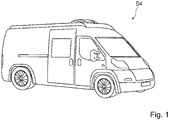
- the Fig. 1 shows a caravan 54 with an interior fitting device.
- the interior finishing device forms in the present case an interior 92 of the vehicle 54 completely.
- FIGS. 2a-2d show the interior fitting device in a schematic plan view in different orientations.
- the interior construction 92 in this case comprises at least two separately formed space regions 10, 12.
- the spatial regions 10, 12 are connected to one another by a passage 64.
- the interior construction device has at least one interior wall 56. The interior wall 56 limits the passage 64.
- a first spatial region 10 of the two spatial regions 10, 12 is designed in the present case as a sanitary area.
- the first space area 10 comprises at least one shower 58.
- the first space area 10 has at least one wash basin 60.
- the shower 58 and the sink 60 are arranged opposite each other.
- the shower 58 and the washbasin 60 are disposed on opposite sides of the first room area 10.
- a second space area 12 of the two space areas 10, 12 is formed in the present case as a sleeping area.
- the second room area 12 comprises at least one bed 62.
- the bed 62 is arranged centrally within the second room area 12.
- the bed 62 occupies a majority of a base area of the second space area 12.
- the interior construction device has at least one movable door unit 14.
- the door unit 14 is movable. By moving the door unit 14, this can be converted into at least two door positions 16, 18.
- a first door position 16 of the door positions 16, 18, the door unit 14 is arranged in a vicinity of the interior wall 56 (see FIG. FIG. 2a ).
- the door unit 14 In the first door position 16, the door unit 14 is arranged outside the passage 64.
- a second door position 18 of the door positions 16, 18, the door unit 14 is arranged outside the vicinity of the interior wall 56.
- the door unit 14 is arranged in the passage 56 (cf. FIGS. 2b-2d ). Accordingly, the door unit 14 separates in the second door position 18 at least partially the first space area 10 and the second space area 12 from each other.
- the interior fitting device may have a different number of door units than the number shown here.
- the interior fitting device has at least one door unit per room area or passage to be separated.
- a plurality of impurities could be provided together for a separation of spatial regions.
- the door unit 14 can be transferred from the first door position 16 into the second door position 18 by at least one displacement of the door unit 14 in a direction transverse to its main extension plane. Further, the door unit 14 from the first door position 16 in the second door position 18 by at least one pivoting of the door unit 14 about a pivot axis, which is oriented at least substantially parallel to the main plane of extension, can be transferred. In the present case, the door unit 14 is simultaneously displaced at least transversely to its main extension plane and pivoted about the pivot axis.
- the interior fitting device has at least one guide unit 28.
- the guide unit 28 is at least partially disposed on an interior ceiling (not shown) of the interior fitting device, a door frame or a canopy of the interior fitting device. Furthermore, the guide unit 28 is at least partially disposed on an upper side of the door unit 14, which faces the interior ceiling.
- the guide unit 28 has at least one first guide element 30.
- the first guide element 30 is arranged on the interior ceiling and / or integrated into it.
- the first guide member 30 is formed as a guide rail.
- the guide unit 28 has at least one second guide element 32.
- the second guide element 32 is arranged on the interior ceiling and / or integrated into it.
- the first guide member 30 is formed as a guide rail.
- the second guide element 32 is formed at least substantially identically to the first guide element 30.
- the first guide element 30 and the second guide element 32 are arranged offset to one another.
- the first guide element 30 and the second guide element 32 are in the present case at an angle to each other arranged. More specifically, a main extension direction of the first guide member 30 is oriented at an angle to a main extension direction of the second guide member 32.
- the guide elements 30, 32 enclose an angle of at most 10 ° to each other.
- the guide elements or their main extension directions are arranged parallel to each other.
- the guide elements 30, 32 or their main extension directions always have an orientation which is different from a vertical orientation.
- the guide unit 28 has at least one first guide element 80 corresponding to the first guide element 30 corresponding to the first corresponding guide element 80.
- the first corresponding guide element 80 is arranged on the upper side of the door unit 14.
- the first guide member 30 and the first corresponding guide member 80 engage each other.
- the first corresponding guide element 80 is freely rotatable about an axis of rotation which is at least substantially parallel to a main extension direction of the door unit 14.
- the first corresponding guide member 80 is formed as a guide roller suspension.
- the guide unit 28 furthermore has at least one second corresponding guide element 82 corresponding to the second guide element 30.
- the second corresponding guide element 82 is arranged on the upper side of the door unit 14.
- the second corresponding guide element 82 is arranged offset to the first corresponding guide element 80 in a direction perpendicular to a main extension direction of the door unit 14.
- the second corresponding guide element 82 is formed at least substantially identical to the first corresponding guide element 80.
- a guide unit could in particular be a further guide unit at least partially on an interior floor of the Interior fitting device and / or on an underside of the door unit, which faces the interior floor, may be arranged.
- the door unit 14 has at least two door elements 20, 22, namely a first door element 20 and a second door element 22.
- the first door element 20 and the second door element 22 are designed as door leaves.
- the door elements 20, 22 are at least partially formed of wood. Furthermore, it is conceivable that these are further formed at least partially from a sheet metal, a plastic, glass, paper, cardboard and / or a textile material. Alternatively, the door elements could be formed of different materials.
- the first door element 20 could be formed, in particular for improving a stability of wood, while the second door element 22 is formed of sheet metal.
- the first door element 20 has an inner side 72. Furthermore, the first door element 20 has an outer side 74. The inside 72 faces the first space area 10. The outer side 74 faces the second space region 10. The second door element 22 has an inner side 76. Furthermore, the second door element 22 has an outer side 78. The inner side 76 of the second door element 22 faces the second space area 12. Furthermore, the inner side 76 of the second door element 22 faces the inner side 72 of the first door element 20. The outer side 78 of the second door element 22 faces the first space region 10.
- the guide unit 28 is arranged on the first door element 20 in the present case.
- the first corresponding guide element 80 and the second corresponding guide element 82 are offset from each other on an upper side of the first door element 20, which faces the interior ceiling, arranged.
- the guide unit could be arranged on the second door element.
- the second door element 22 is at least indirectly coupled to the first door element 20.
- the at least indirect coupling of the door elements 20, 22, the door unit 14 at least one coupling unit 66.
- the coupling unit 66 is arranged between the door elements 20, 22.
- the coupling unit 66 is formed in the present case as a telescopic extension.
- the coupling unit 66 has at least one first coupling element 68 and at least one second coupling element 70 designed to correspond to the first coupling element 68.
- the first coupling element 68 is on the first door element 20 is arranged.
- the first coupling element 68 is arranged on the inner side 72 of the first door element 20.
- the second coupling element 70 is arranged on the second door element 22.
- the second coupling element 70 is arranged on an inner side 76 of the second door element 22.
- the coupling elements 68, 70 engage each other.
- the coupling elements 68, 70 are provided for a mutual guidance of the door elements 20, 22 in particular to a linear guide of this.
- the coupling elements 68, 70 are designed as pull-out rails, preferably telescopic pull-out rails.
- the interior construction device has at least one fixing unit 50, which is provided to fix the door unit 14 in at least one door position 16, 18 (cf. FIG. 5 ).
- the fixing unit 50 fixes the door unit 14 in the second door position 16 (cf. Figures 2c and 2d ).
- the fixing unit 50 is provided for fixing the door unit 14 to an interior floor of the interior fitting device.
- the fixing unit 50 has at least one fixing element 84.
- the fixing unit 50 is at least partially arranged in the first door element 20.
- the fixing element 84 is arranged on the first door element 20.
- the fixing unit or a further fixing unit could be provided for fixing the door unit to an interior ceiling.
- the fixing element 84 is provided for a positive and / or positive fixing of the door unit 14. Furthermore, the fixing unit 50 has a corresponding fixing element 86.
- the corresponding fixing element 86 is arranged on an interior construction floor and / or a guide arranged on the interior installation floor for the door unit 14.
- the fixing element 84 is designed as a fixing pin.
- the corresponding fixing element 86 may be formed as a fixing recess.
- the fixing unit 50 has at least one fixing mechanism 88.
- the fixing mechanism 88 is provided to hold the fixing member 86 under bias. In this way, the fixing element 84 is at least partially in particular biased in the first door member 20 is arranged.
- the fixing unit 50 is at a displacement of the second door member 22 relative to the first door member 20, trigger to fix the door unit 14 in the second door position 18.
- the second door element 22 acts on its movement with at least one actuating element 90 of the fixing unit 50, which is connected to the fixing element 84 is actively connected.
- the actuator 90 is formed in the present case as a lever arm.
- the actuating member 90 is provided to be actuated by the second door member 22.
- the actuating element 90 is provided to trigger the fixing mechanism 88 upon actuation, whereupon the fixing element 84 can be transferred into a fixing position.
- a release of the fixing unit 50 to a transfer of the door unit 14 from the second door position 18 in the first door position 16 is possible by hand at most.
- the door unit 14 forms a sliding door.
- the second door element 22 is displaceable relative to the first door element 20.
- the door unit 14 has two door positions. A first door position in which the first door element 20 and the second door element 22 are arranged one behind the other and a second door position in which the second door element 22 is displaced relative to the first door element 20.
- the second door member 22 is immovably fixed relative to the first door member 20 in the first door position 16.
- the second door element 22 is movable relative to the first door element 20.
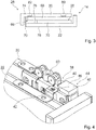
- the interior finishing device For a door position-dependent attachment, the interior finishing device according to at least one fastening unit 38 (see. FIG. 4 ).
- the fastening unit 38 is provided to fix the second door element 22 immobile depending on the door position 16, 18 of the door unit 14 on the first door element 20.
- the fastening unit 38 is at least partially disposed on an upper side of the door unit 14.
- the fastening unit 38 has at least one first fastening element 40.
- the first fastening element 40 is arranged on the first door element 20.
- the fastening element 40 is arranged on the upper side of the first door element 20.
- the second fastening element 42 is arranged on the second door element 22.
- the second fastening element 42 is arranged on an upper side of the second door element 22.
- the first fastening element 40 is designed as a latching element, in particular in FIG Shape of a latching hook, trained.
- the second fastening element 42 is designed as a latching receptacle.
- the first fastening element 40 engages from below into the second fastening element 42.
- the fastening unit 38 forms a latching connection of the first door element 20 with the second door element 22.
- the interior fitting device has at least one release unit 44.
- the trip unit 44 is at least partially disposed on a mecanicausbaudecke.
- the triggering unit 44 has at least one triggering element 46.
- the triggering element 46 forms a stop for the door unit 14 in the second door position 18.
- the triggering element 46 has at least one run-on slope 48.
- the triggering element 46 cooperates with the first fastening element 40 of the fastening unit 38 in the second door position 18 in order to achieve a suspension of the attachment of the first door element 29 and the second door element 22.
- the first fastening element 40 strikes the release unit 46.
- the first fastening element 40 is deformed by the triggering element 46, in particular the starting bevel, whereby a connection of the first fastening element 40 and the second fastening element 42 is released.
- the interior fitting device further comprises at least one further door element 52.
- the further door element 52 is at least substantially identical to the first and / or second door element 22 of the door unit 14. In the present case, the further door element 52 is formed separately from the door unit 14.
- the further door element 52 has at least two door positions. In the first door position, this is arranged on the interior wall 56. In the second door position this at least partially separates the first space area 10 and the second space area 12 from each other. In the first door position, the further door element 52, when the door unit 14 is located in the first door position 16, at least partially hidden therefrom. The further door element 52 is released when the door unit 14 is in the second door position 18. In particular, when the door unit 14 is in the second door position 18 and the door unit 14 has its second door position and the further door element 52 occupies the second door position, the door unit 14, in particular the first door element 20, separate the second door element 22, and the further door element 52, the first space area 10 completely from the second space area 12 from.
- the further door element 52 is at least partially movable in a direction transverse to its main extension plane. Furthermore, the further door element 52 can be transferred from the first door position into the second door position by at least one pivoting of the further door element 52 about a pivot axis which is oriented at least substantially parallel to its main extension plane. In the present case, the further door element 52 is simultaneously displaced at least transversely to its main extension plane and pivoted about the pivot axis.
- a door unit may comprise a further door element as a third door element.
- the further door element could then be pivotable relative to the first and / or second door element in order to carry out a separation of the spatial areas.
- the further door element could be arranged between the first door element and the second door element and thus only released, even if a movement of the second door element to the first door element is released.
- FIG. 6 a schematic flow chart of an exemplary method for selectively at least partially separating the first space area 10 and the second space area 12 with at least the interior finishing device is shown.
- the method comprises a first method step 100.
- the door unit 14 is initially located in the first door position 16 (cf. FIG. 2a ). Furthermore, the door unit 14 has the first door position. The further door element 52 has the first door position.
- the door unit is moved from the first door position 16 into the second door position 18 (cf. FIG. 2b ). In the present case, the door unit 14 is displaced in particular along the guide unit 28. Furthermore, the door unit 14 is pivoted in particular along the guide unit 28. By transferring into the second door position 18, the door elements 20, 22 of the door unit 14 fastened together are released from each other and movable relative to one another.
- the method comprises at least one further method step 102.
- the door unit 14 changes from the first door position to the second Door position transferred (see. Figure 2c ).
- the second door element 22 is moved relative to the first door element 20.
- the fixing unit 50 is triggered, whereby the door unit 14 is firmly fixed in the second door position 18.
- the method comprises at least one further method step 104.
- the further door element 52 is transferred from its first door position into its second door position (cf. Figure 2d ).
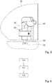
- FIG. 7 shows the interior fitting device with a functional unit 110 and a supply unit 112 for the functional unit 110 in a perspective view.
- the interior fitting device comprises at least one electrically and / or electronically operable functional unit 110.
- the functional unit 110 is arranged on the door unit 14.
- the functional unit 110 is arranged on the first door element 20 of the door unit 14.
- a functional unit could also be arranged on the second door element of the door unit.
- the functional unit could be integrated into the activity unit.
- the functional unit 110 has at least one display unit 120. Furthermore, the functional unit 110 has at least one loudspeaker 122. In the present case, the functional unit 110 forms a television 124. Alternatively, the functional unit could also comprise only the display unit and thus form only one monitor. It is also conceivable that the functional unit only a lighting unit, such as For example, an LED or the like includes, which could be provided to a dependent of the door position lighting the room areas.
- the functional unit 110 can be supplied with at least one electrical signal.
- the electrical signal is provided to a power supply of the functional unit 110.
- the electrical signal ensures a power and / or voltage supply.
- the functional unit 110 can be operated with an electronic signal.
- the electronic signal is provided to a data supply of the functional unit 110.
- the electronic signal ensures a data supply, such as a television signal.
- the electronic signal may in particular be an analog or a digital signal.
- the interior fitting device has at least one supply unit 112.
- the supply unit 112 is provided to supply the functional unit 110, at least as a function of a door position 16, 18 of the door unit 14, with an electrical and / or electronic signal.
- the supply unit 112 supplies the functional unit 10 in the second door position 18 of the door unit 14 with the electrical and / or electronic signal.
- the supply unit 112 can also supply the functional unit 110 in the first door position 16 of the door unit 14.
- the supply unit 112 comprises at least one control unit 126.
- the control unit 126 provides at least the electronic signal.
- the control unit 126 is formed as a television receiver.
- the supply unit 112 has at least one energy supply 128.
- the power supply 128 provides the electronic signal.
- the power supply 128 is formed by a mains plug, which is connected in particular to a vehicle electrical system of the vehicle.
- the supply unit 112 is at least partially integrated into the door unit 14. Alternatively, the supply unit could be partially integrated in the functional unit. The supply unit 112 is partially formed separately from the door unit 14. In the present case, the supply unit 112 is partially arranged on the interior ceiling and / or integrated into a réelleausbaudecke. Alternatively, the supply unit could also be partially arranged and / or integrated in an interior floor, a door frame, or an interior wall.
- the supply unit 112 has at least one contact unit 114.
- the contact unit 114 is provided for the electronic and / or electrical supply of the functional unit 110 to be contacted at least as a function of a door position 16, 18 and which is formed separately from the door unit 14 and / or the functional unit 110.
- the contact unit 114 is arranged on the interior ceiling, in particular in the region of the second door position 18.
- the contact unit 114 has at least two contact elements 118, 119 for the supply of an electrical signal.
- the contact unit 114 has at least two further contact elements 130, 131 for the supply of an electronic signal.
- the contact elements 130, 131 are formed as contact sockets. It is conceivable that the contact unit is arranged on the guide unit 28 for the movable guidance of the door unit 14 and / or is integrated in the guide unit. For example, the contact elements could also be designed as contact pins and / or sliding contacts.
- the supply unit 112 has at least one further contact unit 115.
- the further contact unit 115 is at least substantially identical to the contact unit 114.
- the further contact unit 115 is arranged offset to the contact unit 114.
- the further contact unit 115 is arranged on the interior ceiling and in particular in the area of the first door position 16 of the door unit 14.
- the supply unit 112 has at least one corresponding contact unit 116.
- the corresponding contact unit 116 is formed corresponding to the contact unit 114 and the further contact unit 115.
- the corresponding contact unit 116 contact pins, which are formed corresponding to the contact socket of the contact unit 114 and / or the further contact unit 115.
- the corresponding contact unit 116 is in the present case on the door unit 14 and in particular on an upper side, which faces the interior ceiling, arranged. More specifically, the corresponding contact unit 116 is disposed on the first door member 20 of the door unit 14.
- the corresponding contact unit could also be arranged on the functional unit and / or be integrated at least partially into the door unit and / or the functional unit.
- the corresponding contact unit 116 contacts either the contact unit 114 or the further contact unit 115 in order to provide the functional unit 110 with the electrical and / or electronic signal ( see. Figures 8a, 8b ).
- the corresponding contact unit 116 contacts either the contact unit 114 or the further contact unit 115 in order to provide the functional unit 110 with the electrical and / or electronic signal ( see. Figures 8a, 8b ).
- the functional unit 110 is not supplied with the electrical and / or electronic signal for this case ,
- the supply unit 112 each have a signal strand 132, 134.
- the supply unit 112 has a first signal line 132, which is provided to conduct the electrical signal.
- the first signal strand 132 is integrated in the interior ceiling.
- the first signal string 132 is connected to the contact unit 114.
- the first signal string 132 is connected to the further contact unit 115.
- the first signal string 132 is connected to the power supply 128.
- the supply unit 112 has a second signal string 134, which is provided for supply with the electronic signal.
- the second signal strand 134 is integrated in the interior ceiling.
- the second signal string 134 is connected to the contact unit 114.
- the second signal string 134 is connected to the extended contact unit 116.
- the second signal string 134 is connected to the control unit 126.
- the supply unit 112 has at least one further first signal train 136.
- the further first signal string 136 is integrated in the door unit 14.
- the further first signal string 136 is connected to the corresponding contact unit 116.
- the further first signal string 136 is connected to the functional unit 110.
- the supply unit 112 has at least one further second signal line 138.
- the further second signal strand 138 is integrated in the door unit 14.
- the further second signal strand 138 is connected to the corresponding contact unit 116.
- the further second signal string 138 is connected to the functional unit 110.
- FIG. 9 shows a schematic flowchart of an exemplary method for operating the interior fitting device.
- the method comprises at least one method step 140.
- the door unit 14 is initially located in the first door position 16.
- the further contact unit 115 contacts the corresponding contact unit 116.
- the supply unit 112 supplies the functional unit 110 as a function of the first door position 16 an electrical and / or electronic signal.
- the door unit 14 is moved out of the first door position 16. Then, a contact between the further contact unit 115 and the corresponding contact unit 116 is released.
- the method comprises at least one further method step 142.
- the door unit 14 is moved into the second door position 18.
- the contact unit 114 contacts the corresponding contact unit 116.
- the supply unit 112 supplies the functional unit 110 with an electrical and / or electronic signal depending on the second door position 18.
Abstract
Die Erfindung geht aus von einer Innenausbauvorrichtung für ein Wohnfahrzeug (54), welche wahlweise zu einer zumindest teilweisen Trennung eines ersten Raumbereichs (10) und eines zweiten Raumbereichs (12) des Wohnfahrzeugs (54) vorgesehen ist, mit zumindest einer bewegbaren Türeinheit (14), welche von zumindest einer ersten Türposition (16) in zumindest eine zweite Türposition (18) bewegbar ist und welche zumindest ein erstes Türelement (20) und zumindest ein zweites Türelement (22), welches mit dem ersten Türelement (20) zumindest mittelbar gekoppelt ist, aufweist.Es wird vorgeschlagen, dass in der ersten Türposition (16) das zweite Türelement (22) relativ zum ersten Türelement (20) unbeweglich befestigt ist und in der zweiten Türposition (18) das zweite Türelement (22) relativ zum ersten Türelement (20) bewegbar ist.The invention relates to an interior fitting device for a residential vehicle (54), which is optionally provided for at least partially separating a first spatial region (10) and a second spatial region (12) of the residential vehicle (54), with at least one movable door unit (14) Which can be moved from at least one first door position (16) to at least one second door position (18) and which has at least one first door element (20) and at least one second door element (22) which is at least indirectly coupled to the first door element (20) It is proposed that in the first door position (16) the second door element (22) is fixed immovably relative to the first door element (20) and in the second door position (18) the second door element (22) is fixed relative to the first door element ( 20) is movable.
Description
Die Erfindung betrifft eine Innenausbauvorrichtung nach dem Oberbegriff des Anspruchs 1, sowie ein Verfahren nach dem Oberbegriff des Anspruchs 19.The invention relates to an interior fitting device according to the preamble of
Es ist bereits eine Innenausbauvorrichtung mit zumindest einer Türeinheit, welche zumindest ein erstes Türelement und zumindest ein zweites Türelement umfasst, vorgeschlagen worden.An interior fitting device having at least one door unit, which comprises at least one first door element and at least one second door element, has already been proposed.
Die Aufgabe der Erfindung besteht insbesondere darin, eine gattungsgemäße Vorrichtung mit verbesserten Eigenschaften hinsichtlich einer Flexibilität, insbesondere in Bezug auf eine Raumaufteilung, bereitzustellen. Die Aufgabe wird erfindungsgemäß durch die Merkmale des Patentanspruchs 1 gelöst, während vorteilhafte Ausgestaltungen und Weiterbildungen der Erfindung den Unteransprüchen entnommen werden können.The object of the invention is in particular to provide a generic device with improved properties in terms of flexibility, in particular with respect to a room layout. The object is achieved by the features of
Die Erfindung geht aus von einer Innenausbauvorrichtung für ein Wohnfahrzeug, welche wahlweise zu einer zumindest teilweisen Trennung eines ersten Raumbereichs und eines zweiten Raumbereich des Wohnfahrzeugs vorgesehen ist, mit zumindest einer bewegbaren Türeinheit, welche von zumindest einer ersten Türposition in zumindest einer zweiten Türposition bewegbar ist und welche zumindest ein erstes Türelement und zumindest ein zweites Türelement, welches mit dem ersten Türelement zumindest mittelbar gekoppelt ist, aufweist.The invention is based on an interior fitting device for a motor vehicle, which is optionally provided for at least partially separating a first space area and a second space area of the vehicle, with at least one movable door unit, which is movable from at least one first door position in at least one second door position and which has at least one first door element and at least one second door element which is at least indirectly coupled to the first door element.
Es wird vorgeschlagen, dass in der ersten Türposition das zweite Türelement relativ zum ersten Türelement unbeweglich befestigt ist und in der zweiten Türposition das zweite Türelement relativ zum ersten Türelement bewegbar ist. Hierdurch kann insbesondere eine Flexibilität einer Raumaufteilung verbessert werden. Vorteilhaft kann ein Benutzerkomfort, insbesondere in Bezug auf ein Raumgefühl erzielt werden, wie dies beispielsweise bei einer Hotelsuite der Fall ist. Weiterhin kann sowohl eine besonders vorteilhafte Zugänglichkeit als auch eine Trennung von Raumbereichen untereinander erzielt werden. Des Weiteren kann eine besonders kompakte Anordnung bereitgestellt und somit ein Bauraum reduziert werden.It is proposed that in the first door position, the second door member is immovably fixed relative to the first door member and in the second door position, the second door member is movable relative to the first door member. In this way, in particular a flexibility of a room layout can be improved. Advantageously, a User comfort, especially in terms of a sense of space can be achieved, as is the case for example with a hotel suite. Furthermore, both a particularly advantageous accessibility and a separation of spatial areas can be achieved with each other. Furthermore, a particularly compact arrangement can be provided and thus a space can be reduced.
Unter einer "Innenausbauvorrichtung" für ein Wohnfahrzeug soll insbesondere eine Vorrichtung verstanden werden, welche zu einem Innenausbau eines Wohnfahrzeugs vorgesehen ist. Die Innenausbauvorrichtung ist insbesondere ein funktionstüchtiger, Bestandteil, insbesondere eine Konstruktions- und/oder Funktionskomponente, eines Innenausbaus. Die Innenausbauvorrichtung kann einen Innenausbau zumindest teilweise, vorzugsweise zumindest zu einem Großteil und besonders bevorzugt vollständig ausbilden. Unter "vorgesehen" soll insbesondere speziell programmiert, ausgelegt und/oder ausgestattet verstanden werden. Darunter, dass ein Objekt zu einer bestimmten Funktion vorgesehen ist, soll insbesondere verstanden werden, dass das Objekt diese bestimmte Funktion in zumindest einem Anwendungs- und/oder Betriebszustand erfüllt und/oder ausführt. Unter dem Ausdruck "zumindest zu einem Großteil" soll dabei insbesondere zumindest zu 55 %, vorteilhaft zumindest zu 65 %, vorzugsweise zumindest zu 75 %, besonders bevorzugt zumindest zu 85 % und besonders vorteilhaft zumindest zu 95 % und insbesondere aber auch vollständig verstanden werden. Unter einem "Wohnfahrzeug" soll insbesondere ein Wohnmobil, ein Wohnwagen und/oder ein Kastenwagen verstanden werden. Unter einem "Raumbereich" soll insbesondere ein Sanitärbereich, insbesondere ein Duschbereich und/oder Waschbereich, ein Schlafbereich, ein Wohnbereich, ein Küchenbereich und/oder ein Essbereich verstanden werden. Vorzugsweise ist der erste Raumbereich ein Sanitärbereich. Der Sanitärbereich umfasst vorteilhaft zumindest eine Toilette und/oder ein Waschbecken. Weiter bevorzugt ist der zweite Raumbereich ein Schlafbereich und umfasst zumindest ein Bett, vorzugsweise ein Doppelbett. Unter einer zumindest "teilweisen Trennung" eines ersten Raumbereichs und eines zweiten Raumbereichs soll insbesondere verstanden werden, dass ein Durchgang zwischen zumindest dem ersten Raumbereich und dem zweiten Raumbereich zumindest teilweise, vorzugsweise zumindest zu einem Großteil und besonders bevorzugt vollständig ausbildet. Vorzugsweise ist die Innenausbauvorrichtung zu einer zumindest zu einem Großteil und besonders bevorzugt vollständigen wahlweisen Trennung des Raumbereichs vorgesehen. Unter einer "Türeinheit" soll in diesem Zusammenhang insbesondere eine Einheit verstanden werden, die zu einem wahlweisen zumindest teilweisen Verschließen oder Öffnen von zumindest einem Durchgang zwischen zumindest zwei voneinander trennbaren Raumbereichen vorgesehen ist. Die Türeinheit umfasst vorzugsweise zumindest zwei, vorzugsweise zumindest drei und besonders bevorzugt eine Vielzahl an Türelementen. Insbesondere umfasst die Türeinheit höchstens drei und vorzugsweise höchstens zwei Türelemente. Besonders bevorzugt umfasst die Türeinheit genau zwei Türelemente. Unter einem "Türelement" soll in diesem Zusammenhang insbesondere ein Türblatt, ein Gitter und/oder ein Plissee verstanden werden. Vorteilhaft ist das Türelement zumindest teilweise aus Holz, einem Blech, einem Kunststoff, aus Glas, aus Papier, aus Pappe und/oder aus einem Textilmaterial ausgebildet. Eine Grundfläche des ersten Türelements ist insbesondere zumindest im Wesentlichen identisch zu einer Grundfläche des zweiten Türelements. Unter "zumindest im Wesentlichen" soll in diesem Zusammenhang insbesondere verstanden werden, dass eine Abweichung von einem vorgegebenen Wert insbesondere weniger als 25 %, vorzugsweise weniger als 10 % und besonders bevorzugt weniger als 5 % des vorgegebenen Werts abweicht. Unter "zumindest im Wesentlichen identisch" soll insbesondere bis auf Herstellungs- und/oder Montagetoleranzen identisch verstanden werden. Alternativ kann eine Grundfläche des ersten Türelements größer und vorzugsweise wesentlich größer sein als eine Grundfläche des zweiten Türelements. Unter "Wesentlich größer" soll insbesondere zumindest um 25 %, vorzugsweise um 35 % und besonders bevorzugt zumindest um 45 % größer verstanden werden. Das erste Türelement und das zweite Türelement sind vorzugsweise derart zueinander angeordnet, dass eine Außenseite des ersten Türelements dem zweiten Raumbereich zugewandt ist, eine Innenseite des ersten Türelements dem ersten Raumbereich zugewandt ist, eine Außenseite des zweiten Türelements dem ersten Raumbereich zugewandt ist, eine Innenseite des zweiten Türelements dem zweiten Raumbereich zugewandt ist und/oder die Innenseite des ersten Türelements der Innenseite des zweiten Türelements zugewandt ist. Unter einer Türposition der Türeinheit soll insbesondere eine spezielle Position der Türeinheit verstanden werden. Darunter, dass "zwei Objekte zumindest mittelbar gekoppelt sind" soll insbesondere verstanden werden, dass dies zumindest durch ein weiteres Objekt miteinander vorzugsweise zumindest teilweise zueinander beweglich miteinander verbunden sind. Ferner soll unter mittelbar gekoppelt auch unmittelbar gekoppelt verstanden werden. Die Türelemente sind insbesondere zueinander bewegbar gekoppelt, um zumindest in einer ersten Türstellung und zumindest einer zweiten Türstellung anordenbar zu sein. Unter einer "Türstellung" soll insbesondere eine spezielle Stellung eines ersten Türelements relativ zu einem zweiten Türelement der Türeinheit zueinander verstanden werden. Die Türeinheit weist insbesondere zur zumindest mittelbaren Kopplung des ersten Türelements und des zweiten Türelements zumindest eine Koppeleinheit auf. Die Koppeleinheit ist zumindest teilweise zwischen dem ersten Türelement und dem zweiten Türelement und zwar vorzugsweise an deren jeweiligen Innenseiten angeordnet. Die Koppeleinheit weist insbesondere zumindest ein erstes Koppelelement und zumindest ein zu dem ersten Koppelelement korrespondierend ausgebildetes zweites Koppelelement auf. Das erste Koppelelement ist insbesondere an dem ersten Türelement, insbesondere dessen Innenseite, angeordnet. Das zweite Koppelelement ist insbesondere dem zweiten Türelement, insbesondere dessen Innenseite, angeordnet. Die Koppelelemente sind vorzugsweise als ineinander greifende Auszugsschienen, vorzugsweise Teleskopauszugsschienen ausgebildet. Ferner kann die Koppeleinheit weitere Koppelelemente aufweisen, welche zumindest zwischen dem ersten und dem zweiten Koppelelement angeordnet sind, um beispielsweise eine Auszugslänge der Türelemente zueinander teleskopartig zu vergrößern. Unter einer "unbeweglichen Befestigung zweier Objekte" soll insbesondere verstanden werden, dass diese relativ zueinander in zumindest einem Betriebszustand frei von jeglichem Freiheitsgrad der Bewegung sind. Insbesondere in der ersten Türstellung der Türeinheit sind die Türelemente hintereinander angeordnet und unbeweglich zueinander befestigt. In der zweiten Türstellung sind das erste Türelement und das zweite Türelement zumindest teilweise zueinander verschoben. Vorzugsweise bildet die Türeinheit, insbesondere das zweite Türelement in Relation zum dem ersten Türelement, eine Schiebetür aus. Ferner ist denkbar, dass das zweite Türelement zu dem ersten Türelement drehbar und/oder verschwenkbar zueinander ausgebildet sein könnte.An "interior fitting device" for a caravan is to be understood in particular to mean a device which is provided for interior fitting of a caravan. The interior fitting device is in particular a functional component, in particular a construction and / or functional component, of an interior construction. The interior construction device can form an interior construction at least partially, preferably at least to a large extent and particularly preferably completely. By "provided" is intended to be understood in particular specially programmed, designed and / or equipped. The fact that an object is intended for a specific function should in particular mean that the object fulfills and / or executes this specific function in at least one application and / or operating state. At least 55%, advantageously at least 65%, preferably at least 75%, particularly preferably at least 85%, and particularly advantageously at least 95%, and in particular also completely, should be understood by the term "at least to a large extent". A "caravan" is to be understood in particular a motorhome, a caravan and / or a van. A "room area" is to be understood in particular as meaning a sanitary area, in particular a shower area and / or washing area, a sleeping area, a living area, a kitchen area and / or a dining area. Preferably, the first room area is a sanitary area. The sanitary area advantageously comprises at least one toilet and / or a washbasin. More preferably, the second room area is a sleeping area and comprises at least one bed, preferably a double bed. An "at least partial separation" of a first spatial region and a second spatial region should in particular be understood to mean that a passage between at least the first spatial region and the second spatial region forms at least partially, preferably at least to a large extent and particularly preferably completely. Preferably, the interior fitting device is provided for at least a majority, and particularly preferably complete, optional separation of the spatial area. Under a "door unit" should in this Connection should be understood in particular a unit which is provided for an optional at least partially closing or opening of at least one passage between at least two separable space regions. The door unit preferably comprises at least two, preferably at least three and particularly preferably a plurality of door elements. In particular, the door unit comprises at most three and preferably at most two door elements. Particularly preferably, the door unit comprises exactly two door elements. A "door element" is to be understood in this context, in particular a door leaf, a grid and / or a pleated. Advantageously, the door element is at least partially made of wood, a metal sheet, a plastic, glass, paper, cardboard and / or a textile material. A base area of the first door element is in particular at least substantially identical to a base area of the second door element. By "at least substantially" is to be understood in this context in particular that a deviation from a predetermined value, in particular less than 25%, preferably less than 10% and more preferably less than 5% of the predetermined value deviates. The term "at least substantially identical" should be understood to mean identical except for manufacturing and / or assembly tolerances. Alternatively, a base area of the first door element may be larger and preferably substantially larger than a base area of the second door element. By "substantially greater" is meant in particular at least 25%, preferably 35% and more preferably at least 45% greater. The first door element and the second door element are preferably arranged relative to each other such that an outer side of the first door element faces the second space area, an inner side of the first door element faces the first space area, an outer side of the second door element faces the first space area, an inner side of the first door element second door member facing the second space portion and / or the inside of the first door member facing the inside of the second door member. A door position of the door unit is to be understood in particular as meaning a special position of the door unit. By the fact that "two objects are coupled at least indirectly" is to be understood in particular that these are preferably at least partially interconnected by at least one other object with each other. Furthermore, indirectly coupled should also be understood to be directly coupled. The door elements are in particular coupled to one another in a movable manner, at least in a first door position and at least one second door position to be arranged. A "door position" is to be understood in particular a special position of a first door element relative to a second door element of the door unit to each other. The door unit has at least one coupling unit, in particular for the at least indirect coupling of the first door element and the second door element. The coupling unit is at least partially disposed between the first door element and the second door element and preferably at their respective inner sides. The coupling unit has, in particular, at least one first coupling element and at least one second coupling element, which corresponds to the first coupling element. The first coupling element is arranged in particular on the first door element, in particular its inside. The second coupling element is in particular the second door element, in particular the inside, arranged. The coupling elements are preferably designed as interlocking pull-out rails, preferably telescopic pull-out rails. Furthermore, the coupling unit may have further coupling elements, which are arranged at least between the first and the second coupling element, for example, to telescopically enlarge an extension length of the door elements to each other. By "immovable attachment of two objects" is to be understood in particular that they are relative to each other in at least one operating state free of any degree of freedom of movement. In particular, in the first door position of the door unit, the door elements are arranged one behind the other and fixed immovably to each other. In the second door position, the first door element and the second door element are at least partially shifted from each other. The door unit, in particular the second door element, preferably forms a sliding door in relation to the first door element. It is also conceivable that the second door element to the first door member could be rotatable and / or pivotable to each other.
Es wird ferner vorgeschlagen, dass die Türeinheit dazu vorgesehen ist, in der ersten Türposition die Raumbereiche frei zu geben und in der zweiten Türposition zumindest teilweise den ersten Raumbereich von dem zweiten Raumbereich zu trennen. Hierdurch kann vorteilhaft eine Flexibilität einer Raumaufteilung weiter verbessert werden. In der ersten Türposition ist die Türeinheit insbesondere in einem Nahbereich einer Innenausbauwand der Innenausbauvorrichtung angeordnet. Vorzugsweise liegt die Türeinheit zumindest mittelbar an der Innenausbauwand an. In der zweiten Türposition ist die Türeinheit vorzugsweise außerhalb des Nahbereichs der Innenausbauwand angeordnet. Unter einem "Nahbereich" eines Objekts soll insbesondere ein Bereich verstanden werden, welcher durch einen maximalen Abstand zu diesem Objekt von höchstens 30 cm, vorzugsweise höchstens 20 cm und besonders bevorzugt höchstens 10 cm definiert ist.It is further proposed that the door unit is provided to release the room areas in the first door position and to at least partially separate the first room area from the second room area in the second door position. As a result, advantageously a flexibility of a room layout can be further improved. In the first door position, the door unit is arranged in particular in a vicinity of an interior wall of the interior fitting device. Preferably, the door unit rests at least indirectly on the interior wall. In the second door position, the door unit is preferably outside the vicinity of the interior wall arranged. A "near zone" of an object should in particular be understood as a region which is defined by a maximum distance to this object of at most 30 cm, preferably at most 20 cm and particularly preferably at most 10 cm.
Des Weiteren wird vorgeschlagen, dass die Türeinheit von der ersten Türposition in die zweite Türposition durch zumindest eine Verschiebung der Türeinheit in einer Richtung quer zu deren Haupterstreckungsebene überführbar ist. Hierdurch kann eine besonders flexible Raumteilung erzielt werden. Unter einer "Haupterstreckungsebene" eines Objekts soll insbesondere eine Ebene verstanden werden, welche parallel zu einer größten Seitenfläche eines kleinsten gedachten Quaders ist, welcher die Baueinheit gerade noch vollständig umschließt, und insbesondere durch den Mittelpunkt des Quaders verläuft. Unter "quer" soll vorzugsweise verschieden von zumindest im Wesentlichen parallel verstanden werden. Vorzugsweise soll unter "quer" zumindest im Wesentlichen senkrecht verstanden werden. Unter "zumindest im Wesentlichen parallel" soll hier insbesondere eine Ausrichtung einer Richtung relativ zu einer Bezugsrichtung, insbesondere in einer Ebene, verstanden werden, wobei die Richtung und die Bezugsrichtung einen Winkel von 0° insbesondere unter Berücksichtigung einer maximalen Abweichung von kleiner als 8°, vorteilhaft von kleiner als 5° und besonders vorteilhaft von kleiner als 2° einschließt. Unter "zumindest im Wesentlichen senkrecht" soll hier insbesondere eine Ausrichtung einer Richtung relativ zu einer Bezugsrichtung, insbesondere in einer Ebene, verstanden werden, wobei die Richtung und die Bezugsrichtung einen Winkel von 90° insbesondere unter Berücksichtigung einer maximalen Abweichung von kleiner als 8°, vorteilhaft von kleiner als 5° und besonders vorteilhaft von kleiner als 2° einschließt.Furthermore, it is proposed that the door unit can be transferred from the first door position into the second door position by at least one displacement of the door unit in a direction transverse to its main extension plane. As a result, a particularly flexible space division can be achieved. A "main plane of extension" of an object should be understood in particular to mean a plane which is parallel to a largest side surface of a smallest imaginary cuboid which just completely surrounds the structural unit, and in particular runs through the center of the cuboid. By "transverse", it is preferable to mean different from at least substantially parallel. Preferably, "transverse" should be understood to mean at least substantially perpendicular. By "at least substantially parallel" should be understood here in particular an alignment of a direction relative to a reference direction, in particular in a plane, wherein the direction and the reference direction an angle of 0 °, in particular taking into account a maximum deviation of less than 8 °, advantageously less than 5 °, and more preferably less than 2 °. The term "at least substantially perpendicular" is to be understood here as meaning in particular an alignment of a direction relative to a reference direction, in particular in a plane, the direction and the reference direction being at an angle of 90 °, in particular taking into account a maximum deviation of less than 8 °, advantageously less than 5 °, and more preferably less than 2 °.
Des Weiteren wird vorgeschlagen, dass die Türeinheit von der ersten Türposition in die zweite Türposition durch zumindest ein Verschwenken der Türeinheit um eine Schwenkachse, welche zumindest im Wesentlichen parallel zu deren Haupterstreckungsebene, insbesondere deren Haupterstreckungsrichtung und zwar vorzugsweise in der ersten Türposition der Türeinheit, orientiert ist, überführbar ist. Hierdurch kann eine ganz besonders flexible Raumteilung erzielt werden. Unter einer "Haupterstreckungsrichtung" eines Objekts soll dabei insbesondere eine Richtung verstanden werden, welche parallel zu einer längsten Kante eines kleinsten geometrischen Quaders verläuft, welcher das Objekt gerade noch vollständig umschließt. Vorzugsweise ist denkbar, dass die Türeinheit insbesondere durch eine Kombination einer Verschiebung und einer Schwenkbewegung in die zweite Türposition überführbar ist. Insbesondere ist eine Verschwenkung von höchstens 30° vorzugsweise höchstens 25°, weiter bevorzugt höchstens 20° und ganz besonders bevorzugt höchstens 15° denkbar.Furthermore, it is proposed that the door unit be oriented from the first door position into the second door position by at least pivoting the door unit about a pivot axis which is at least substantially parallel to its main extension plane, in particular its main extension direction and preferably in the first door position of the door unit , is convertible. As a result, a very flexible space division can be achieved. A "main extension direction" of an object should be understood to mean, in particular, a direction which runs parallel to a longest edge of a smallest geometric cuboid which just completely encloses the object. Preferably, it is conceivable that the door unit can be transferred in particular by a combination of a displacement and a pivoting movement in the second door position. In particular, a pivoting of at most 30 °, preferably at most 25 °, more preferably at most 20 ° and very particularly preferably at most 15 ° conceivable.
Es wird weiter vorgeschlagen, dass die Innenausbauvorrichtung zumindest eine Führungseinheit umfasst, welche zur Führung der Türeinheit vorgesehen ist, wobei die Führungseinheit zumindest ein erstes Führungselement und zumindest ein zweites Führungselement umfasst, welche zueinander parallel oder winklig zueinander angeordnet sind. Hierdurch kann auf konstruktiv vorteilhafte Art und Weise eine Verschiebung und/oder Verschwenkung der Türeinheit erzielt werden. Insbesondere sind die Haupterstreckungsrichtungen der Führungselemente zueinander parallel oder winklig angeordnet. Vorzugsweise weisen die Führungselemente zueinander eine Orientierung auf, welche von einer zumindest im Wesentlichen senkrechten Orientierung verschieden ist. Bevorzugt schließen die Führungselemente, insbesondere die Haupterstreckungsrichtungen der Führungselemente einen Winkel miteinander ein, welcher höchstens 30° vorzugsweise höchstens 25°, weiter bevorzugt höchstens 20° und ganz besonders bevorzugt höchstens 15° beträgt. Ferner ist die Führungseinheit, insbesondere die Führungselemente, zumindest teilweise an einer Innenausbaudecke, wie beispielsweise einem Baldachin, angeordnet und/oder in diese integriert. Alternativ oder zusätzlich könnten Führungselemente, insbesondere zusätzliche Führungselemente an einem Innenausbauboden angeordnet und/oder integriert sein. Die Führungselemente sind vorzugsweise als Führungsschienen ausgebildet. Die Führungseinheit ist insbesondere zumindest teilweise an der Türeinheit, insbesondere einer Innenausbaudecke zugewandten Oberseite der Türeinheit angeordnet. Ferner weist die Führungseinheit insbesondere zumindest zwei zu den jeweiligen ersten und zweiten Führungselementen korrespondierende Führungselemente auf. Die korrespondierenden Führungselemente sind an einer Oberseite der Türeinheit, welche der Innenausbaudecke zugewandt ist angeordnet und/oder integriert und zwar insbesondere an dem ersten Türelement. Die korrespondierenden Führungselemente sind zueinander in einer Richtung senkrecht zur Haupterstreckungsrichtung der Türeinheit voneinander beabstandet. Ferner sind die korrespondierenden Führungselemente insbesondere um eine Drehachse drehbar gelagert, welche parallel zur Haupterstreckungsrichtung der Türeinheit ist. Die korrespondierenden Führungselemente greifen insbesondere zur Führung der Türeinheit jeweils in eines der Führungselemente ein.It is further proposed that the interior fitting device comprises at least one guide unit which is provided for guiding the door unit, wherein the guide unit comprises at least a first guide element and at least one second guide element, which are mutually parallel or at an angle to each other. In this way, a displacement and / or pivoting of the door unit can be achieved in a structurally advantageous manner. In particular, the main directions of extension of the guide elements are arranged parallel to each other or at an angle. The guide elements preferably have an orientation to one another, which is different from an at least substantially perpendicular orientation. The guide elements, in particular the main directions of extension of the guide elements, preferably form an angle with one another which is at most 30 °, preferably at most 25 °, more preferably at most 20 ° and very particularly preferably at most 15 °. Furthermore, the guide unit, in particular the guide elements, at least partially disposed on an interior ceiling, such as a canopy, and / or integrated into this. Alternatively or additionally, guide elements, in particular additional guide elements, could be arranged and / or integrated on an interior design floor. The guide elements are preferably designed as guide rails. The guide unit is in particular arranged at least partially on the door unit, in particular an interior ceiling facing top of the door unit. Furthermore, the guide unit has in particular at least two guide elements corresponding to the respective first and second guide elements. The corresponding guide elements are arranged on an upper side of the door unit, which faces the interior ceiling and / or integrated and in particular on the first door element. The corresponding guide elements are spaced from each other in a direction perpendicular to the main extension direction of the door unit. Furthermore, the corresponding guide elements are in particular rotatably mounted about an axis of rotation, which parallel to the main extension direction of Door unit is. The corresponding guide elements engage in particular for guiding the door unit in each case in one of the guide elements.
Es wird zudem vorgeschlagen, dass die Innenausbauvorrichtung zumindest eine Befestigungseinheit umfasst, welche zu einer von der Türposition abhängigen Kraft und/oder formschlüssigen Befestigung des zweiten Türelements an dem ersten Türelement vorgesehen ist. Hierdurch kann eine Sicherheit verbessert werden, da ein ungewolltes Bewegen der Türelemente zueinander in einer nicht dazu vorgesehenen Türposition vermieden werden kann. Weiter vorteilhaft kann eine Flexibilität verbessert werden, da bei einem Umbau zur Trennung von Raumbereichen eine Bewegung der ersten und zweiten Türelemente zueinander unberücksichtigt bleiben kann. Unter einer "kraft- und/oder formschlüssigen Befestigung" soll dabei insbesondere eine lösbare Befestigung verstanden werden, wobei eine Haltekraft zwischen zwei Bauteilen vorzugsweise durch einen geometrischen Eingriff der Bauteile ineinander und/oder eine Reibkraft zwischen den Bauteilen übertragen wird. Die Befestigungseinheit ist insbesondere an einer Oberseite der Türeinheit, insbesondere den Türelementen angeordnet. Besonders bevorzugt weist die Befestigungseinheit zumindest ein erstes Befestigungselement, welches an dem ersten Türelement angeordnet ist und zumindest ein zu dem ersten Befestigungselement korrespondierend ausgebildetes zweites Befestigungselement, welches an dem zweiten Türelement angeordnet ist, auf. Bei einer Befestigung der Türelemente zueinander greifen das Befestigungselement und das weitere Befestigungselement ineinander ein. Besonders vorteilhaft bildet die Befestigungseinheit eine Rastverbindung aus. Vorzugsweise ist zumindest eines der Befestigungselemente als ein Rastelement und ein weiteres der Befestigungselemente, insbesondere das zweite Befestigungselement als ein korrespondierendes Rastelement ausgebildet. Vorzugsweise bildet das erste Befestigungselement einen Rasthaken aus während das zweite eine korrespondierende Rastaufnahme ausbildet. Ferner ist denkbar, dass die Befestigungseinheit weitere Befestigungsmechanismen nutzen kann wie beispielsweise einen Magnetmechanismus oder dergleichen.It is also proposed that the interior fitting device comprises at least one fastening unit which is provided for a force dependent on the door position and / or positive fastening of the second door element to the first door element. As a result, a security can be improved because an unwanted movement of the door elements to each other in a door position not provided for this purpose can be avoided. Further advantageously, flexibility can be improved, since a movement of the first and second door elements relative to one another can be disregarded in the case of a conversion for the separation of spatial regions. A "non-positive and / or positive attachment" is to be understood in particular a releasable attachment, wherein a holding force between two components preferably by a geometric engagement of the components into one another and / or a frictional force between the components is transmitted. The fastening unit is arranged in particular on an upper side of the door unit, in particular the door elements. Particularly preferably, the fastening unit has at least one first fastening element, which is arranged on the first door element and at least one second fastening element, which is designed correspondingly to the first fastening element and which is arranged on the second door element. When the door elements are fastened to one another, the fastening element and the further fastening element engage in one another. Particularly advantageously, the fastening unit forms a latching connection. Preferably, at least one of the fastening elements is designed as a latching element and another of the fastening elements, in particular the second fastening element as a corresponding latching element. Preferably, the first fastening element forms a latching hook while the second forms a corresponding latching receptacle. Furthermore, it is conceivable that the fastening unit can use further attachment mechanisms, such as a magnetic mechanism or the like.
Weiterhin wird vorgeschlagen, dass die Innenausbauvorrichtung zumindest eine Auslöseeinheit umfasst, welche zumindest, die zumindest ein Auslöseelement aufweist, welches dazu vorgesehen ist, eine Befestigung des zweiten Türelements mit dem ersten Türelement abhängig von einer Türposition der Türeinheit aufzuheben. Hierdurch kann insbesondere eine Flexibilität weiter verbessert werden. Besonders vorteilhaft kann eine automatische Auslösung der Befestigung erzielt werden, wodurch ein Umbau weiter vereinfacht werden kann. Die Auslöseeinheit ist insbesondere an einer Innenausbaudecke des Innenraumausbaus angeordnet und/oder integriert. Das Auslöseelement bildet insbesondere einen Anschlag für die Führungseinheit aus. Die Auslöseeinheit ist insbesondere zu einer mechanischen Auslösung der Befestigung vorgesehen.Furthermore, it is proposed that the interior fitting device comprises at least one triggering unit, which at least has at least one triggering element, which is intended to cancel an attachment of the second door element with the first door element depending on a door position of the door unit. This can in particular a flexibility can be further improved. Particularly advantageous, an automatic release of the attachment can be achieved, whereby a conversion can be further simplified. The trip unit is arranged and / or integrated in particular on an interior ceiling of the interior design. The triggering element in particular forms a stop for the guide unit. The trip unit is provided in particular for a mechanical release of the attachment.
Es wird ferner vorgeschlagen, dass das Auslöseelement mit zumindest einem Befestigungselement der Befestigungseinheit in der zweiten Türposition zu einer Aufhebung der Befestigung des ersten Türelements und des zweiten Türelements zusammenwirkt. Besonders bevorzugt weist Auslöseelement zumindest eine Anlaufschräge auf. Hierdurch kann ein besonders benutzerfreundlicher Mechanismus bereitgestellt werden. Die Anlaufschräge ist vorzugsweise in Richtung einer Bewegung, welche zur Überführung von der ersten Türposition in die zweite Türposition gerichtet. Bei einer Bewegung gegen die Türeinheit in die zweite Türposition wird das erste Befestigungselement von dem Auslöseelement, insbesondere durch Auflaufen dessen auf die Anlaufschräge abgelenkt und zumindest teilweise verformt, wodurch eine Verbindung zwischen dem ersten Befestigungselement und dem zweiten korrespondierenden Befestigungselement aufgehoben wird.It is further proposed that the triggering element cooperate with at least one fastening element of the fastening unit in the second door position to cancel the fastening of the first door element and the second door element. Particularly preferably, the triggering element has at least one run-on slope. This can provide a particularly user-friendly mechanism. The run-on slope is preferably in the direction of a movement, which is directed to the transfer from the first door position to the second door position. In a movement against the door unit in the second door position, the first fastening element is deflected by the trigger element, in particular by running it on the run-on slope and at least partially deformed, whereby a connection between the first fastener and the second corresponding fastener is released.
Es wird vorgeschlagen, dass die Innenausbauvorrichtung zumindest eine Fixiereinheit umfasst, welche dazu vorgesehen ist, die Türeinheit in zumindest einer Türposition, insbesondere der zweiten Türposition, zu fixieren. Hierdurch kann insbesondere eine Betriebssicherheit und/oder eine Stabilität der Vorrichtung verbessert werden. Die Fixiereinheit ist insbesondere zu einer Fixierung der Türeinheit an einem Innenausbauboden des Innenausbaus vorgesehen. Alternativ oder zusätzlich könnte die Fixiereinheit oder eine weitere Fixiereinheit zu einer Fixierung der Türeinheit an einer Innenausbaudecke vorgesehen sein. Die Fixiereinheit weist insbesondere zumindest ein Fixierelement auf, welches zu einer kraft- und/oder formschlüssigen Fixierung der Türeinheit vorgesehen ist. Vorzugsweise weist die Fixiereinheit ein korrespondierendes Fixierelement auf. Das korrespondierende Fixierelement ist insbesondere an einem Innenausbauboden und/oder ein an dem Innenausbauboden angeordneten Führung für die Türeinheit angeordnet. Beispielsweise ist das Fixierelement als ein Fixierpin ausgebildet. Ferner kann das korrespondierende Fixierelement als eine Fixierausnehmung ausgebildet sein. Ferner weist die Fixiereinheit zumindest einen Fixiermechanismus auf, welcher dazu vorgesehen ist, das Fixierelement unter Vorspannung zu halten. Die Fixierelement ist vorzugsweise zumindest teilweise insbesondere vorgespannt in dem ersten Türelement angeordnet.It is proposed that the interior fitting device comprises at least one fixing unit which is provided to fix the door unit in at least one door position, in particular the second door position. In this way, in particular, operational safety and / or stability of the device can be improved. The fixing unit is provided in particular for fixing the door unit to an interior floor of the interior. Alternatively or additionally, the fixing unit or a further fixing unit could be provided for fixing the door unit to an interior ceiling. The fixing unit has in particular at least one fixing element, which is provided for a positive and / or positive fixing of the door unit. Preferably, the fixing unit has a corresponding fixing element. The corresponding fixing element is arranged, in particular, on an interior floor and / or a guide arranged on the interior floor for the door unit. For example, the fixing element is designed as a fixing pin. Furthermore, the corresponding fixing element as a Fixierausnehmung be formed. Furthermore, the fixing unit has at least one fixing mechanism, which is provided to keep the fixing element under prestress. The fixing element is preferably at least partially biased in particular arranged in the first door element.
Es wird vorgeschlagen, dass die Fixiereinheit dazu vorgesehen ist, bei einer Verschiebung des zweiten Türelements relativ zum ersten Türelement, auszulösen um die Türeinheit in der zweiten Türposition zu fixieren. Hierdurch kann insbesondere eine Betriebssicherheit und/oder eine Stabilität der Vorrichtung weiter verbessert werden. Insbesondere beaufschlagt das zweite Türelement bei dessen Bewegung zumindest ein Betätigungselement der Fixiereinheit, welches mit dem Fixierelement wirkverbunden ist. Vorzugsweise ist das Betätigungselement als ein Hebelarm ausgebildet. Insbesondere ist das Betätigungselement höchstens bei einer Bewegung des zweiten Türelements von dem ersten Türelement weg durch diese auslösbar. Bei einer Bewegung des zweiten Türelements relativ zur ersten Türelement ist das Betätigungselement dazu vorgesehen, von dem zweiten Türelement betätigt zu werden. Ferner ist das Betätigungselement dazu vorgesehen, den Fixiermechanismus bei einer Betätigung auszulösen, wodurch das Fixierelement in eine Fixierstellung überführbar ist. Vorzugsweise ist ein Lösen der Fixiereinheit und einer Überführung der Türeinheit von der zweiten Türposition in die erste Position höchstens händisch möglich.It is proposed that the fixing unit is provided to trigger upon a displacement of the second door element relative to the first door element, in order to fix the door unit in the second door position. In this way, in particular, operational safety and / or stability of the device can be further improved. In particular, the second door element acts upon its movement at least one actuating element of the fixing unit, which is operatively connected to the fixing element. Preferably, the actuating element is designed as a lever arm. In particular, the actuating element can be triggered by the first door element at most during a movement of the second door element through it. In a movement of the second door member relative to the first door member, the actuating element is provided to be actuated by the second door member. Further, the actuating element is provided to trigger the fixing mechanism during actuation, whereby the fixing element can be transferred into a fixing position. Preferably, a release of the fixing unit and a transfer of the door unit from the second door position to the first position by hand at most possible.
Es wird vorgeschlagen, dass die Innenausbauvorrichtung zumindest ein weiteres Türelement umfasst, welches separat von der Türeinheit ausgebildet ist. Hierdurch kann insbesondere eine Flexibilität weiter verbessert werden. Vorzugsweise ist das weitere Türelement zumindest teilweise verschiebbar und/oder verschwenkbar. Insbesondere weist die Innenausbauvorrichtung für das weitere Türelement zumindest eine weitere Führungseinheit auf. Die weitere Führungseinheit ist vorzugsweise von der Führungseinheit separat ausgebildet. Insbesondere umfasst die weitere Führungseinheit zumindest ein weiteres Führungselement dessen Haupterstreckungsrichtung winklig zu zumindest einer Haupterstreckungsrichtung zumindest einer der Führungselemente der Führungseinheit orientiert ist. Das weitere Türelement weist insbesondere zumindest zwei Türstellungen auf. Insbesondere in einer ersten Türelementstellung des weiteren Türelements ist das weitere Türelement an der Innenausbauwand, vorzugsweise zwischen Türeinheit und Innenausbauwand, und zwar vorzugsweise dem zweiten Türelement der Türeinheit und der Innenausbauwand angeordnet. In einer zweiten Türstellung ist das weitere Türelement zwischen der Innenausbauwand quer zwischen der Innenausbauwand und der Türeinheit, insbesondere dem zweiten Türelement der Türeinheit, angeordnet.It is proposed that the interior fitting device comprises at least one further door element, which is formed separately from the door unit. In this way, in particular flexibility can be further improved. Preferably, the further door element is at least partially displaceable and / or pivotable. In particular, the interior fitting device for the further door element has at least one further guide unit. The further guide unit is preferably formed separately from the guide unit. In particular, the further guide unit comprises at least one further guide element whose main extension direction is oriented at an angle to at least one main extension direction of at least one of the guide elements of the guide unit. The further door element has in particular at least two door positions. Particularly in a first door element position of the further door element, the further door element is on the interior wall, preferably between the door unit and the interior wall, preferably the second one Door element of the door unit and the interior wall arranged. In a second door position, the further door element between the interior wall is arranged transversely between the interior wall and the door unit, in particular the second door element of the door unit.
Es wird vorgeschlagen, dass das weitere Türelement in der ersten Türposition der Türeinheit zumindest teilweise von der Türeinheit verdeckt angeordnet ist. Hierdurch kann insbesondere ein Bauraum verringert werden, da das weitere Türelement vorteilhaft verstaut werden kann. Die erste Türstellung des weiteren Türelements tritt insbesondere zumindest dann auf, wenn sich die Türeinheit in der ersten Türposition befindet. Für diesen Fall ist das weitere Türelement insbesondere zwischen der Innenausbauwand und der Türeinheit angeordnet und somit beidseitig verdeckt.It is proposed that the further door element in the first door position of the door unit is at least partially hidden from the door unit. In this way, in particular a space can be reduced because the other door element can be stowed advantageous. The first door position of the further door element occurs in particular at least when the door unit is in the first door position. For this case, the further door element is arranged in particular between the interior wall and the door unit and thus concealed on both sides.
Um insbesondere einen Benutzerkomfort weiter zur erhöhen wird vorteilhaft vorgeschlagen, dass das weitere Türelement in der zweiten Türposition der Türeinheit von der Türeinheit frei gegeben ist. Die zweite Türstellung des weiteren Türelements tritt insbesondere zumindest dann auf, wenn sich die Türeinheit in der zweiten Türposition befindet. Für diesen Fall ist das weitere Türelement von der Türeinheit freigegeben, so dass dieses quer insbesondere zwischen der Innenausbauwand und der Türeinheit angeordnet und somit beidseitig verdeckt ist. Besonders bevorzugt ist das weitere Türelement zumindest in der zweiten Türposition zumindest teilweise zur Trennung des ersten Raumbereichs von dem zweiten Raumbereich vorgesehen.To further increase user comfort in particular, it is advantageously proposed that the further door element in the second door position of the door unit be released from the door unit. The second door position of the further door element occurs in particular at least when the door unit is in the second door position. In this case, the further door element is released from the door unit, so that it is arranged transversely in particular between the interior wall and the door unit and thus concealed on both sides. Particularly preferably, the further door element is provided at least partially in the second door position for separating the first space area from the second space area.
Es wird ein Verfahren zur wahlweise zumindest teilweisen Trennung eines ersten Raumbereichs und eines zweiten Raumbereichs eines Wohnfahrzeugs mit zumindest einer Innenausbauvorrichtung vorgeschlagen, bei welchem in zumindest einem Verfahrensschritt zumindest eine Türeinheit, welche zumindest ein erstes Türelement und zumindest ein zweites Türelement umfasst, welches zumindest mittelbar mit dem ersten Türelement gekoppelt ist, in einer ersten Türposition das zweite Türelement relativ zum ersten Türelement unbeweglich befestigt wird, wobei in zumindest einem weiteren Verfahrensschritt die Türeinheit von der ersten Türposition in zumindest eine zweite Türposition bewegt wird, wobei in der zweiten Türposition das zweite Türelement relativ zum ersten Türelement bewegt wird. Hierdurch kann insbesondere eine Flexibilität einer Raumtrennung verbessert werden.At least one door unit, which comprises at least one first door element and at least one second door element, which at least indirectly with. In at least one method step, a method for selectively at least partially separation of a first space and a second space portion of a vehicle with at least one interior construction proposed is coupled to the first door element, in a first door position, the second door member is immovably fixed relative to the first door element, wherein in at least one further method step, the door unit is moved from the first door position to at least a second door position, wherein in the second door position, the second door element relative is moved to the first door element. In this way, in particular a flexibility of a room separation can be improved.
Weitere Vorteile ergeben sich aus der folgenden Zeichnungsbeschreibung. In den Zeichnungen ist ein Ausführungsbeispiel der Erfindung dargestellt. Die Zeichnungen, die Beschreibung und die Ansprüche enthalten zahlreiche Merkmale in Kombination. Der Fachmann wird die Merkmale zweckmäßigerweise auch einzeln betrachten und zu sinnvollen weiteren Kombinationen zusammenfassen.Further advantages emerge from the following description of the drawing. In the drawings, an embodiment of the invention is shown. The drawings, the description and the claims contain numerous features in combination. The person skilled in the art will expediently also consider the features individually and combine them into meaningful further combinations.
Es zeigen:
- Fig. 1
- Wohnfahrzeug mit einer Innenausbauvorrichtung,
- Fig. 2
- verschiedene Anordnungen eines Teils der Innenausbauvorrichtung mit einer Türeinheit zu einer zumindest teilweisen Trennung von Raumbereichen in verschiedenen Ausrichtungen,
- Fig. 3
- einen Teil der Innenausbauvorrichtung mit der Türeinheit, in einer Draufsicht,
- Fig. 4
- einen Teil der Innenausbauvorrichtung mit der Türeinheit, einer Befestigungseinheit und einer Auslöseeinheit in einer perspektivischen Ansicht,
- Fig. 5
- einen Teil der Innenausbauvorrichtung mit der Türeinheit und einer Fixiereinheit in einer perspektivischen Seitenansicht,
- Fig. 6
- einen schematischen Ablaufplan eines beispielhaften Verfahrens zum Betrieb der Innenausbauvorrichtung,
- Fig. 7
- einen Teil der Innenausbauvorrichtung mit einer Funktionseinheit und einer Versorgungseinheit in einer perspektivischen Ansicht,
- Fig. 8
- einen Teil der Innenausbauvorrichtung in verschiedenen Positionen der Türeinheit in einer perspektivischen Ansicht und
- Fig. 9
- einen schematischen Ablaufplan eines beispielhaften Verfahrens zum Betrieb der Innenausbauvorrichtung.
- Fig. 1
- Residential vehicle with an interior fitting device,
- Fig. 2
- various arrangements of a part of the interior fitting device with a door unit for at least partial separation of spatial areas in different orientations,
- Fig. 3
- a part of the interior fitting device with the door unit, in a plan view,
- Fig. 4
- a part of the interior fitting device with the door unit, a fastening unit and a release unit in a perspective view,
- Fig. 5
- a part of the interior fitting device with the door unit and a fixing unit in a perspective side view,
- Fig. 6
- a schematic flowchart of an exemplary method for operating the interior fitting device,
- Fig. 7
- a part of the interior fitting device with a functional unit and a supply unit in a perspective view,
- Fig. 8
- a part of the interior fitting device in different positions of the door unit in a perspective view and
- Fig. 9
- a schematic flowchart of an exemplary method for operating the interior fitting device.
Die
Die
Der Innenausbau 92 umfasst dabei zumindest zwei separat voneinander ausgebildete Raumbereiche 10, 12. Die Raumbereiche 10, 12 sind durch einen Durchgang 64 miteinander verbunden. Die Innenausbauvorrichtung weist zumindest eine Innenausbauwand 56 auf. Die Innenausbauwand 56 begrenzt den Durchgang 64.The
Ein erster Raumbereich 10 der zwei Raumbereiche 10, 12 ist im vorliegenden Fall als ein Sanitärbereich ausgebildet. Der erste Raumbereich 10 umfasst im vorliegenden Fall zumindest eine Dusche 58. Ferner weist der erste Raumbereich 10 zumindest ein Waschbecken 60 auf. Die Dusche 58 und das Waschbecken 60 sind aneinander gegenüberliegend angeordnet. Die Dusche 58 und das Waschbecken 60 sind an gegenüberliegenden Seiten des ersten Raumbereichs 10 angeordnet.A first
Ein zweiter Raumbereich 12 der zwei Raumbereiche 10, 12 ist im vorliegenden Fall als ein Schlafbereich ausgebildet. Der zweite Raumbereich 12 umfasst zumindest ein Bett 62. Im vorliegenden Fall ist das Bett 62 zentral innerhalb des zweiten Raumbereichs 12 angeordnet. Das Bett 62 nimmt einen Großteil einer Grundfläche des zweiten Raumbereichs 12 ein.A
Es sind ferner weitere Kombinationen und Ausgestaltungen von Raumbereichen denkbar. Insbesondere könnten weitere Raumbereiche vorhanden sein und/oder die Raumbereiche verschieden ausgestaltet sein, wie beispielsweise als Sanitärbereich, ein Schlafbereich, ein Wohnbereich, ein Küchenbereich und/oder ein Essbereich oder dergleichen.Further combinations and configurations of spatial regions are also conceivable. In particular, further room areas could be present and / or the room areas could be configured differently, for example as a sanitary area, a sleeping area, a living area, a kitchen area and / or a dining area or the like.
Zur wahlweise zumindest teilweisen Trennung des ersten Raumbereichs 10 und des zweiten Raumbereichs 12 weist die Innenausbauvorrichtung zumindest eine bewegbare Türeinheit 14 auf. Die Türeinheit 14 ist bewegbar. Durch Bewegung der Türeinheit 14 ist diese in zumindest in zwei Türpositionen 16, 18 überführbar. In einer ersten Türposition 16 der Türpositionen 16, 18 ist die Türeinheit 14 in einem Nahbereich der Innenausbauwand 56 angeordnet (vgl.
Ferner ist denkbar, dass die Innenausbauvorrichtung eine von der hier gezeigten Anzahl, abweichende Anzahl an Türeinheiten aufweisen kann. Beispielsweise weist die Innenausbauvorrichtung je abzutrennenden Raumbereich bzw. Durchgang zumindest eine Türeinheit auf. Ferner ist denkbar, dass mehrere Unreinheiten gemeinsam zu einer Trennung von Raumbereichen vorgesehen sein könnten.Furthermore, it is conceivable that the interior fitting device may have a different number of door units than the number shown here. For example, the interior fitting device has at least one door unit per room area or passage to be separated. Furthermore, it is conceivable that a plurality of impurities could be provided together for a separation of spatial regions.
Die Türeinheit 14 ist von der ersten Türposition 16 in die zweite Türposition 18 durch zumindest eine Verschiebung der Türeinheit 14 in einer Richtung quer zu deren Haupterstreckungsebene überführbar. Ferner ist die Türeinheit 14 von der ersten Türposition 16 in die zweite Türposition 18 durch zumindest ein Verschwenken der Türeinheit 14 um eine Schwenkachse, welche zumindest im Wesentlichen parallel zu deren Haupterstreckungsebene orientiert ist, überführbar. Im vorliegenden Fall wird die Türeinheit 14 gleichzeitig zumindest quer zu deren Haupterstreckungsebene verschoben und um die Schwenkachse verschwenkt.The
Zur Führung der Türeinheit 14 weist die Innenausbauvorrichtung zumindest eine Führungseinheit 28 auf. Die Führungseinheit 28 ist zumindest teilweise an einer Innenausbaudecke (nicht dargestellt) der Innenausbauvorrichtung, eines Türrahmens oder einem Baldachin der Innenausbauvorrichtung angeordnet. Ferner ist die Führungseinheit 28 zumindest teilweise an einer Oberseite der Türeinheit 14, welche der Innenausbaudecke zugewandt ist, angeordnet.To guide the
Die Führungseinheit 28 weist zumindest ein erstes Führungselement 30 auf. Das erste Führungselement 30 ist an der Innenausbaudecke angeordnet und/oder in diese integriert. Das erste Führungselement 30 ist als eine Führungsschiene ausgebildet. Ferner weist die Führungseinheit 28 zumindest ein zweites Führungselement 32 auf. Das zweite Führungselement 32 ist an der Innenausbaudecke angeordnet und/oder in diese integriert. Das erste Führungselement 30 ist als eine Führungsschiene ausgebildet. Das zweite Führungselement 32 ist zumindest im Wesentlichen identisch zum ersten Führungselement 30 ausgebildet. Das erste Führungselement 30 und das zweite Führungselement 32 sind zueinander versetzt angeordnet. Das erste Führungselement 30 und das zweite Führungselement 32 sind im vorliegenden Fall zueinander winklig angeordnet. Genauer gesagt ist eine Haupterstreckungsrichtung des ersten Führungselements 30 winklig zu einer Haupterstreckungsrichtung des zweiten Führungselements 32 orientiert. Die Führungselemente 30, 32 schließen einen Winkel von höchstens 10° zueinander ein. Alternativ ist denkbar, dass die Führungselemente bzw. deren Haupterstreckungsrichtungen zueinander parallel angeordnet sind. Die Führungselemente 30, 32 bzw. deren Haupterstreckungsrichtungen weisen jedoch stets eine Orientierung auf, welche von einer senkrechten Orientierung verschieden ist.The
Die Führungseinheit 28 weist zumindest ein zum dem ersten Führungselement 30 korrespondierend ausgebildetes erstes korrespondierendes Führungselement 80 auf. Das erste korrespondierende Führungselement 80 ist an der Oberseite der Türeinheit 14 angeordnet. Das erste Führungselement 30 und das erste korrespondierende Führungselement 80 greifen ineinander ein. Das erste korrespondierende Führungselement 80 ist um eine Drehachse, welche zumindest im Wesentlichen parallel zu einer Haupterstreckungsrichtung der Türeinheit 14 ist, frei drehbar. Das erste korrespondierende Führungselement 80 ist als eine Führungsrollenaufhängung ausgebildet.The
Die Führungseinheit 28 weist ferner zumindest ein zum dem zweiten Führungselement 30 korrespondierend ausgebildetes zweites korrespondierendes Führungselement 82 auf. Das zweite korrespondierende Führungselement 82 ist an der Oberseite der Türeinheit 14 angeordnet. Das zweite korrespondierende Führungselement 82 ist versetzt zu dem ersten korrespondierenden Führungselement 80 angeordnet und zwar in einer Richtung senkrecht zu einer Haupterstreckungsrichtung der Türeinheit 14. Das zweite korrespondierende Führungselement 82 ist zumindest im Wesentlichen identisch zum ersten korrespondierenden Führungselement 80 ausgebildet.The
Durch die winklige Anordnung der Führungselemente 30, 32, sowie die drehbare Ausgestaltung der korrespondierenden Führungselemente 80, 82 erlaubt die Führungseinheit 28 bei einer Bewegung der Türeinheit 14, beispielsweise bei einer Überführung von der ersten Türposition 16 in die zweite Türposition 18, dass sich diese gleichzeitig verschieben und verschwenken lässt.Due to the angled arrangement of the
Alternativ oder zusätzlich könnte eine Führungseinheit insbesondere eine weitere Führungseinheit zumindest teilweise an einem Innenausbauboden der Innenausbauvorrichtung und/oder an einer Unterseite der Türeinheit, welche dem Innenausbauboden zugewandt ist, angeordnet sein.Alternatively or additionally, a guide unit could in particular be a further guide unit at least partially on an interior floor of the Interior fitting device and / or on an underside of the door unit, which faces the interior floor, may be arranged.
Die Türeinheit 14 weist zumindest zwei Türelemente 20, 22 auf und zwar ein erstes Türelement 20 und ein zweites Türelement 22. Das erste Türelement 20 und das zweite Türelement 22 sind als Türblätter ausgebildet. Die Türelemente 20, 22 sind zumindest teilweise aus Holz ausgebildet. Ferner ist denkbar, dass diese weiter zumindest teilweise aus einem Blech, einem Kunststoff, aus Glas, aus Papier, aus Pappe und/oder aus einem Textilmaterial ausgebildet sind. Alternativ könnten die Türelemente aus verschiedenen Materialen ausgebildet sein. Beispielsweise könnte das erste Türelement 20, insbesondere zur Verbesserung einer Stabilität aus Holz ausgebildet sein, während das zweite Türelement 22 aus Blech ausgebildet ist.The
Das erste Türelement 20 weist eine Innenseite 72 auf. Ferner weist das erste Türelement 20 eine Außenseite 74 auf. Die Innenseite 72 ist dem ersten Raumbereich 10 zugewandt. Die Außenseite 74 ist dem zweiten Raumbereich 10 zugewandt. Das zweite Türelement 22 weist eine Innenseite 76 auf. Ferner weist das zweite Türelement 22 eine Außenseite 78 auf. Die Innenseite 76 des zweiten Türelements 22 ist dem zweiten Raumbereich 12 zugewandt. Ferner ist die Innenseite 76 des zweiten Türelements 22 der Innenseite 72 des ersten Türelements 20 zugewandt. Die Außenseite 78 des zweiten Türelements 22 ist dem ersten Raumbereich 10 zugewandt.The
Die Führungseinheit 28 ist im vorliegenden Fall an dem ersten Türelement 20 angeordnet. Das erste korrespondierende Führungselement 80 und das zweite korrespondierende Führungselement 82 sind zueinander versetzt an einer Oberseite des ersten Türelements 20, welche der Innenausbaudecke zugewandt ist, angeordnet. Alternativ oder zusätzlich könnte die Führungseinheit an dem zweiten Türelement angeordnet.The
Das zweite Türelement 22 ist zumindest mittelbar mit dem ersten Türelement 20 gekoppelt. Das zur zumindest mittelbaren Koppelung der Türelemente 20, 22 weist die Türeinheit 14 zumindest eine Koppeleinheit 66 auf. Die Koppeleinheit 66 ist zwischen den Türelementen 20, 22 angeordnet. Die Koppeleinheit 66 ist im vorliegenden Fall als ein Teleskopauszug ausgebildet. Die Koppeleinheit 66 weist zumindest ein erstes Koppelelement 68 und zumindest ein zu dem ersten Koppelelement 68 korrespondierend ausgebildetes zweites Koppelelement 70 auf. Das erste Koppelelement 68 ist an dem ersten Türelement 20 angeordnet. Das erste Koppelelement 68 ist an der Innenseite 72 des ersten Türelements 20 angeordnet. Das zweite Koppelelement 70 ist an dem zweiten Türelement 22 angeordnet. Das zweite Koppelelement 70 ist an einer Innenseite 76 des zweiten Türelements 22 angeordnet. Die Koppelelemente 68, 70 greifen ineinander ein. Die Koppelelemente 68, 70 sind zu einer gegenseitigen Führung der Türelemente 20, 22 insbesondere zu einer Linearführung dieser vorgesehen. Die Koppelelemente 68, 70 sind als Auszugsschienen, vorzugsweise Teleskopauszugsschienen, ausgebildet.The
Die Innenausbauvorrichtung weist zumindest eine Fixiereinheit 50 auf, welche dazu vorgesehen ist, die Türeinheit 14 in zumindest einer Türposition 16, 18 zu fixieren (vgl.
Das Fixierelement 84 ist zu einer kraft- und/oder formschlüssigen Fixierung der Türeinheit 14 vorgesehen. Ferner weist die Fixiereinheit 50 ein korrespondierendes Fixierelement 86 auf. Das korrespondierende Fixierelement 86 ist an einem Innenausbauboden und/oder einer an dem Innenausbauboden angeordneten Führung für die Türeinheit 14 angeordnet. Beispielsweise ist das Fixierelement 84 als ein Fixierpin ausgebildet. Ferner kann das korrespondierende Fixierelement 86 als eine Fixierausnehmung ausgebildet sein.The fixing
Ferner weist die Fixiereinheit 50 zumindest einen Fixiermechanismus 88 auf. Der Fixiermechanismus 88 ist dazu vorgesehen, das Fixierelement 86 unter Vorspannung zu halten. Derart ist das Fixierelement 84 ist zumindest teilweise insbesondere vorgespannt in dem ersten Türelement 20 angeordnet.Furthermore, the fixing
Die Fixiereinheit 50 ist bei einer Verschiebung des zweiten Türelements 22 relativ zum ersten Türelement 20, auszulösen um die Türeinheit 14 in der zweiten Türposition 18 zu fixieren. Das zweite Türelement 22 beaufschlagt dessen Bewegung mit zumindest einem Betätigungselement 90 der Fixiereinheit 50, welches mit dem Fixierelement 84 wirkverbunden ist. Das Betätigungselement 90 ist im vorliegenden Fall als ein Hebelarm ausgebildet. Bei einer Bewegung des zweiten Türelements 22 relativ zum ersten Türelement 20 ist das Betätigungselement 90 dazu vorgesehen, von dem zweiten Türelement 22 betätigt zu werden. Ferner ist das Betätigungselement 90 dazu vorgesehen, den Fixiermechanismus 88 bei einer Betätigung auszulösen, woraufhin das Fixierelement 84 in eine Fixierstellung überführbar ist. Ein Lösen der Fixiereinheit 50 zu einer Überführung der Türeinheit 14 von der zweiten Türposition 18 in die erste Türposition 16 ist höchstens händisch möglich.The fixing
Die Türeinheit 14 bildet eine Schiebetür aus. Das zweite Türelement 22 ist relativ zu dem ersten Türelement 20 verschiebbar. Demnach weist die Türeinheit 14 zwei Türstellungen auf. Eine erste Türstellung in, welcher das erste Türelement 20 und das zweite Türelement 22 hintereinander angeordnet sind und eine zweite Türstellung, in welcher das zweite Türelement 22 relativ zum ersten Türelement 20 verschoben ist. Dabei ist eine Bewegbarkeit der Türelemente 20, 22 zueinander jedoch abhängig von der Türposition 16, 18 der Türeinheit 14. Im vorliegenden Fall ist in der ersten Türposition 16 das zweite Türelement 22 relativ zum ersten Türelement 20 unbeweglich befestigt. In der zweiten Türposition 18 hingegen ist das zweite Türelement 22 relativ zum ersten Türelement 20 bewegbar.The
Zu einer türpositionsabhängigen Befestigung weist die Innenausbauvorrichtung nach zumindest eine Befestigungseinheit 38 auf (vgl.
Die Befestigungseinheit 38 weist zumindest ein erstes Befestigungselement 40 auf. Das erste Befestigungselement 40 ist an dem ersten Türelement 20 angeordnet. Das Befestigungselement 40 ist an der Oberseite des ersten Türelements 20 angeordnet. Ferner weist die Befestigungseinheit 38 und zumindest ein zu dem ersten Befestigungselement 40 korrespondierend ausgebildetes zweites Befestigungselement 42 auf. Das zweite Befestigungselement 42 ist an dem zweiten Türelement 22 angeordnet. Das zweite Befestigungselement 42 ist an einer Oberseite des zweiten Türelements 22 angeordnet. Das erste Befestigungselement 40 ist als ein Rastelement, insbesondere in Form eines Rasthakens, ausgebildet. Das zweite Befestigungselement 42 ist als eine Rastaufnahme ausgebildet. Das erste Befestigungselement 40 rastet von unten her in das zweite Befestigungselement 42 ein. Dabei bildet die Befestigungseinheit 38 eine Rastverbindung des ersten Türelements 20 mit dem zweiten Türelement 22 aus.The
Um eine Befestigung des zweiten Türelements 22 mit dem ersten Türelement 20 aufzuheben weist die Innenausbauvorrichtung zumindest eine Auslöseeinheit 44 auf. Die Auslöseeinheit 44 ist zumindest teilweise an einer Innenausbaudecke angeordnet. Die Auslöseeinheit 44 weist zumindest ein Auslöseelement 46 auf. Das Auslöseelement 46 bildet einen Anschlag für die Türeinheit 14 in der zweiten Türposition 18 aus. Das Auslöseelement 46 weist zumindest eine Anlaufschräge 48 auf. Das Auslöseelement 46 wirkt mit dem ersten Befestigungselement 40 der Befestigungseinheit 38 in der zweiten Türposition 18 zusammen um eine Aufhebung der Befestigung des ersten Türelements 29 und des zweiten Türelements 22 zu erzielen. Dabei läuft bei der Bewegung der Türeinheit 14 in die zweite Türposition 18 das erste Befestigungselement 40 auf die Auslöseeinheit 46 auf. Das erste Befestigungselement 40 wird durch das Auslöseelement 46, insbesondere die Anlaufschräge, verformt, wodurch eine Verbindung des ersten Befestigungselements 40 und des zweiten Befestigungselements 42 aufgehoben wird.In order to remove an attachment of the
Die Innenausbauvorrichtung weist ferner zumindest ein weiteres Türelement 52 auf. Das weitere Türelement 52 ist zumindest im Wesentlichen identisch zu dem ersten und/oder zweiten Türelement 22 der Türeinheit 14 ausgebildet. Im vorliegenden Fall ist das weitere Türelement 52 von der Türeinheit 14 separat ausgebildet.The interior fitting device further comprises at least one
Das weitere Türelement 52 weist zumindest zwei Türstellungen auf. In der ersten Türstellung ist dieses an der Innenausbauwand 56 angeordnet. In der zweiten Türstellung trennt dieses zumindest teilweise den ersten Raumbereich 10 und den zweiten Raumbereich 12 voneinander ab. In der ersten Türstellung ist das weitere Türelement 52, wenn sich die Türeinheit 14 in der ersten Türposition 16 befindet zumindest teilweise von dieser verdeckt angeordnet. Das weitere Türelement 52 ist freigegeben, wenn sich die Türeinheit 14 in der zweiten Türposition 18 befindet. Insbesondere wenn sich die Türeinheit 14 in der zweiten Türposition 18 befindet und die Türeinheit 14 ihre zweite Türstellung aufweist und das weitere Türelement 52 dessen zweite Türstellung einnimmt, trennen die Türeinheit 14, insbesondere das erste Türelement 20, das zweite Türelement 22, und das weitere Türelement 52 den ersten Raumbereich 10 vollständig von dem zweiten Raumbereich 12 ab.The
Dazu ist das weitere Türelement 52 zumindest teilweise in einer Richtung quer zu dessen Haupterstreckungsebene bewegbar. Ferner ist das weitere Türelement 52 von der ersten Türstellung in die zweite Türstellung durch zumindest ein Verschwenken des weiteren Türelements 52 um eine Schwenkachse, welches zumindest im Wesentlichen parallel zu deren Haupterstreckungsebene orientiert ist, überführbar. Im vorliegenden Fall wird das weitere Türelement 52 gleichzeitig zumindest quer zu deren Haupterstreckungsebene verschoben und um die Schwenkachse verschwenkt.For this purpose, the
Alternativ oder zusätzlich ist denkbar, dass eine Türeinheit ein weiteres Türelement als ein drittes Türelement umfassen kann. Beispielsweise könnte dann das weitere Türelement relativ zum ersten und/oder zweiten Türelement verschwenkbar sein, um eine Trennung der Raumbereiche durchzuführen. Ferner könnte das weitere Türelement zwischen dem ersten Türelement und dem zweiten Türelement angeordnet sein und derart lediglich freigegeben werden, wenn auch eine Bewegung des zweiten Türelements zu dem ersten Türelement freigegeben wird.Alternatively or additionally, it is conceivable that a door unit may comprise a further door element as a third door element. For example, the further door element could then be pivotable relative to the first and / or second door element in order to carry out a separation of the spatial areas. Furthermore, the further door element could be arranged between the first door element and the second door element and thus only released, even if a movement of the second door element to the first door element is released.
In
Das Verfahren umfasst einen ersten Verfahrensschritt 100. In dem ersten Verfahrensschritt 100 befindet sich die Türeinheit 14 zunächst in der ersten Türposition 16 (vgl.
Das Verfahren umfasst zumindest einen weiteren Verfahrensschritt 102. In dem weiteren Verfahrensschritt 102 wird die Türeinheit 14 von der ersten Türstellung in die zweite Türstellung überführt (vgl.
Das Verfahren umfasst zumindest einen weiteren Verfahrensschritt 104. In dem weiteren Verfahrensschritt 104 wird das weitere Türelement 52 von dessen erster Türstellung in dessen zweite Türstellung überführt (vgl.
Insbesondere um die Raumbereiche 10, 12 wiederum miteinander zu verbinden können, müssen die oben genannten Verfahrensschritte in einer umgekehrten Reihenfolge durchgeführt werden. Dabei muss jedoch zumindest die Fixiereinheit 50 von Hand gelöst werden.In particular, in order to be able to connect the
Hinsichtlich weiterer Verfahrensschritte des Verfahrens zu einem Betrieb der Vorrichtung darf auf die vorhergehende Beschreibung der Vorrichtung verwiesen werden, da diese Beschreibung analog auch auf das Verfahren zu lesen ist und somit alle Merkmale hinsichtlich der Vorrichtung auch in Bezug auf das Verfahren zu einem Betrieb der Vorrichtung als offenbart gelten.With regard to further method steps of the method for operating the device, reference may be made to the preceding description of the device, since this description is also analogous to the method to read and thus all features with respect to the device with respect to the method for operation of the device disclosed apply.
Die Innenausbauvorrichtung umfasst zumindest eine elektrisch und/oder elektronisch betreibbare Funktionseinheit 110 auf. Die Funktionseinheit 110 ist an der Türeinheit 14 angeordnet. Im vorliegenden Fall ist die Funktionseinheit 110 an dem ersten Türelement 20 der Türeinheit 14 angeordnet. Alternativ könnte eine Funktionseinheit auch an dem zweiten Türelement der Türeinheit angeordnet sein. Ferner ist denkbar, dass die Funktionseinheit in die Tateinheit integriert sein könnte.The interior fitting device comprises at least one electrically and / or electronically operable functional unit 110. The functional unit 110 is arranged on the
Die Funktionseinheit 110 weist zumindest eine Anzeigeeinheit 120 auf. Ferner weist die Funktionseinheit 110 zumindest einen Lautsprecher 122 auf. Im vorliegenden Fall bildet die Funktionseinheit 110 einen Fernseher 124 aus. Alternativ könnte die Funktionseinheit auch nur die Anzeigeeinheit umfassen und somit lediglich einen Monitor ausbilden. Auch ist denkbar, dass die Funktionseinheit lediglich eine Beleuchtungseinheit, wie beispielsweise eine LED oder dergleichen umfasst, welche zu einer von der Türposition abhängigen Beleuchtung der Raumbereiche vorgesehen sein könnten.The functional unit 110 has at least one
Die Funktionseinheit 110 ist zumindest mit einem elektrischen Signal versorgbar. Das elektrische Signal ist zu einer Energieversorgung der Funktionseinheit 110 vorgesehen. Beispielsweise stellt das elektrische Signal eine Strom- und/oder Spannungsversorgung sicher. Ferner ist die Funktionseinheit 110 mit einem elektronischen Signal betreibbar. Das elektronische Signal ist zu einer Datenversorgung der Funktionseinheit 110 vorgesehen. Beispielsweise stellt das elektronische Signal eine Datenversorgung sicher, wie beispielsweise ein Fernsehsignal. Bei dem elektronischen Signal kann es sich dabei insbesondere um ein analoges oder ein digitales Signal handeln.The functional unit 110 can be supplied with at least one electrical signal. The electrical signal is provided to a power supply of the functional unit 110. For example, the electrical signal ensures a power and / or voltage supply. Furthermore, the functional unit 110 can be operated with an electronic signal. The electronic signal is provided to a data supply of the functional unit 110. For example, the electronic signal ensures a data supply, such as a television signal. The electronic signal may in particular be an analog or a digital signal.
Ferner weist die Innenausbauvorrichtung zumindest eine Versorgungseinheit 112 auf. Die Versorgungseinheit 112 ist dazu vorgesehen, die Funktionseinheit 110 zumindest abhängig von einer Türposition 16, 18 der Türeinheit 14 mit einem elektrischen und/oder elektronischen Signal zu versorgen. Die Versorgungseinheit 112 versorgt die Funktionseinheit 10 in der zweiten Türposition 18 der Türeinheit 14 mit dem elektrischen und/oder elektronischen Signal. Zusätzlich kann die Versorgungseinheit 112 die Funktionseinheit 110 auch in der ersten Türposition 16 der Türeinheit 14 versorgen.Furthermore, the interior fitting device has at least one
Die Versorgungseinheit 112 umfasst zumindest eine Steuereinheit 126. Die Steuereinheit 126 stellt zumindest das elektronische Signal zur Verfügung. Im vorliegenden Fall ist die Steuereinheit 126 als ein Fernsehreceiver ausgebildet. Ferner weist die Versorgungseinheit 112 zumindest eine Energieversorgung 128 auf. Die Energieversorgung 128 stellt das elektronische Signal zur Verfügung. Im vorliegenden Fall ist die Energieversorgung 128 von einem Netzstecker gebildet, welcher insbesondere mit einem Bordnetz des Wohnfahrzeugs verbunden ist.The
Die Versorgungseinheit 112 ist zumindest teilweise in die Türeinheit 14 integriert. Alternativ könnte die Versorgungseinheit teilweise in die Funktionseinheit integriert sein. Die Versorgungseinheit 112 ist teilweise separat von der Türeinheit 14 ausgebildet. Im vorliegenden Fall ist die Versorgungseinheit 112 teilweise an der Innenausbaudecke angeordnet und/oder in eine Innenausbaudecke integriert. Alternativ könnte die Versorgungseinheit auch teilweise in einem Innenausbauboden, einem Türrahmen, oder einer Innenausbauwand angeordnet und/oder integriert sein.The
Die Versorgungseinheit 112 weist zumindest eine Kontakteinheit 114 auf. Die Kontakteinheit 114 ist zur elektronischen und/oder elektrischen Versorgung der Funktionseinheit 110 dazu vorgesehen, zumindest abhängig von einer Türposition 16, 18 kontaktiert zu werden und welche separat von der Türeinheit 14 und/oder der Funktionseinheit 110 ausgebildet ist. Die Kontakteinheit 114 ist an der Innenausbaudecke und zwar insbesondere im Bereich der zweiten Türposition 18 angeordnet. Die Kontakteinheit 114 weist zumindest zwei Kontaktelemente 118, 119 für die Versorgung mit einem elektrischen Signal auf. Ferner weist die Kontakteinheit 114 zumindest zwei weitere Kontaktelemente 130, 131 für die Versorgung mit einem elektronischen Signal auf. Die Kontaktelemente 130, 131 sind als Kontaktbuchsen ausgebildet. Denkbar ist, dass die Kontakteinheit an der Führungseinheit 28 zur beweglichen Führung der Türeinheit 14 angeordnet und/oder in die Führungseinheit integriert ist. Beispielsweise könnten die Kontaktelemente auch als Kontaktstifte und/oder Schleifkontakte ausgebildet sein.The
Ferner weist die Versorgungseinheit 112 zumindest eine weitere Kontakteinheit 115 auf. Die weitere Kontakteinheit 115 ist zumindest im Wesentlichen identisch mit der Kontakteinheit 114 ausgebildet. Die weitere Kontakteinheit 115 ist versetzt zu der Kontakteinheit 114 angeordnet. Die weitere Kontakteinheit 115 ist an der Innenausbaudecke angeordnet und zwar insbesondere im Bereich der ersten Türposition 16 der Türeinheit 14.Furthermore, the
Ferner weist die Versorgungseinheit 112 zumindest eine korrespondierende Kontakteinheit 116 auf. Die korrespondierende Kontakteinheit 116 ist korrespondierend zur Kontakteinheit 114 und der weiteren Kontakteinheit 115 ausgebildet. Dazu weist die korrespondierende Kontakteinheit 116 Kontaktstifte auf, welche korrespondierend zu der Kontaktbuchse der Kontakteinheit 114 und/oder der weiteren Kontakteinheit 115 ausgebildet sind. Die korrespondierende Kontakteinheit 116 ist im vorliegenden Fall an der Türeinheit 14 und zwar insbesondere an einer Oberseite, welche der Innenausbaudecke zugewandt ist, angeordnet. Genauer gesagt ist die korrespondierende Kontakteinheit 116 an dem ersten Türelement 20 der Türeinheit 14 angeordnet. Alternativ könnte die korrespondierende Kontakteinheit auch an der Funktionseinheit angeordnet sein und/oder zumindest teilweise in die Türeinheit und/oder die Funktionseinheit integriert sein.Furthermore, the
Abhängig von der Position der Türeinheit 14, insbesondere der ersten Türposition 16 und/oder der zweiten Türposition 18 kontaktiert die korrespondierende Kontakteinheit 116 entweder die Kontakteinheit 114 oder die weitere Kontakteinheit 115, um die Funktionseinheit 110 mit dem elektrischen und/oder elektronischen Signal zu versorgen (vgl.
Zu einer Leitung des elektrischen und/oder elektronischen Signals weist die Versorgungseinheit 112 jeweils einen Signalstrang 132, 134 auf. Die Versorgungseinheit 112 weist einen ersten Signalstrang 132 auf, welcher zu Leitung des elektrischen Signals vorgesehen ist. Der erste Signalstrang 132 ist in der Innenausbaudecke integriert. Der erste Signalstrang 132 ist mit der Kontakteinheit 114 verbunden. Der erste Signalstrang 132 ist mit der weiteren Kontakteinheit 115 verbunden. Der erste Signalstrang 132 ist mit der Energieversorgung 128 verbunden. Ferner weist die Versorgungseinheit 112 einen zweiten Signalstrang 134 auf, welcher zu Versorgung mit dem elektronischen Signal vorgesehen ist. Der zweite Signalstrang 134 ist in der Innenausbaudecke integriert. Der zweite Signalstrang 134 ist mit der Kontakteinheit 114 verbunden. Ferner ist der zweite Signalstrang 134 mit der weiterten Kontakteinheit 116 verbunden. Zudem ist der zweite Signalstrang 134 mit der Steuereinheit 126 verbunden.To a line of the electrical and / or electronic signal, the
Ferner weist die Versorgungseinheit 112 zumindest einen weiteren ersten Signalstrang 136 auf. Der weitere erste Signalstrang 136 ist in der Türeinheit 14 integriert. Der weitere erste Signalstrang 136 ist mit der korrespondierenden Kontakteinheit 116 verbunden. Ferner ist der weitere erste Signalstrang 136 mit der Funktionseinheit 110 verbunden. Ferner weist die Versorgungseinheit 112 zumindest einen weiteren zweiten Signalstrang 138 auf. Der weitere zweite Signalstrang 138 ist in der Türeinheit 14 integriert. Der weitere zweite Signalstrang 138 ist mit der korrespondierenden Kontakteinheit 116 verbunden. Der weitere zweite Signalstrang 138 ist mit der Funktionseinheit 110 verbunden.Furthermore, the
Das Verfahren umfasst zumindest einen Verfahrensschritt 140. Die Türeinheit 14 befindet sich zunächst in der ersten Türposition 16. In der ersten Türposition 16 kontaktiert die weitere Kontakteinheit 115 die korrespondierende Kontakteinheit 116. Demnach versorgt die Versorgungseinheit 112 abhängig von der ersten Türposition 16 die Funktionseinheit 110 mit einem elektrischen und/oder elektronischen Signal. In dem Verfahrensschritt 140 wird die Türeinheit 14 aus der ersten Türposition 16 heraus bewegt. Daraufhin wird ein Kontakt zwischen der weiteren Kontakteinheit 115 und der korrespondierenden Kontakteinheit 116 aufgehoben.The method comprises at least one
Das Verfahren umfasst zumindest einen weiteren Verfahrensschritt 142. In dem weiteren Verfahrensschritt 142 wird die Türeinheit 14 in die zweite Türposition 18 bewegt. In der zweiten Türposition 18 kontaktiert die Kontakteinheit 114 die korrespondierende Kontakteinheit 116. Demnach versorgt die Versorgungseinheit 112 abhängig von der zweiten Türposition 18 die Funktionseinheit 110 mit einem elektrischen und/oder elektronischen Signal.The method comprises at least one
Claims (18)
Priority Applications (1)
| Application Number | Priority Date | Filing Date | Title |
|---|---|---|---|
| SI201930115T SI3575154T1 (en) | 2018-05-30 | 2019-05-23 | Interior construction device |
Applications Claiming Priority (1)
| Application Number | Priority Date | Filing Date | Title |
|---|---|---|---|
| DE102018112981.5A DE102018112981A1 (en) | 2018-05-30 | 2018-05-30 | Interior device |
Publications (2)
| Publication Number | Publication Date |
|---|---|
| EP3575154A1 true EP3575154A1 (en) | 2019-12-04 |
| EP3575154B1 EP3575154B1 (en) | 2021-07-21 |
Family
ID=66647057
Family Applications (1)
| Application Number | Title | Priority Date | Filing Date |
|---|---|---|---|
| EP19176087.5A Active EP3575154B1 (en) | 2018-05-30 | 2019-05-23 | Interior construction device |
Country Status (3)
| Country | Link |
|---|---|
| EP (1) | EP3575154B1 (en) |
| DE (1) | DE102018112981A1 (en) |
| SI (1) | SI3575154T1 (en) |
Citations (6)
| Publication number | Priority date | Publication date | Assignee | Title |
|---|---|---|---|---|
| DE1192937B (en) * | 1958-03-25 | 1965-05-13 | Dethleffs Geb | Arrangement and design of the doors inside a caravan |
| DE29600388U1 (en) * | 1996-01-11 | 1996-03-07 | Grimm Wohnmobile Und Wohnwagen | Arrangement on a sanitary cell in a vehicle |
| DE102005021702A1 (en) * | 2005-05-11 | 2007-05-31 | Dohmeyer, Jan, Dipl.-Ing. | Bathroom for camping mobile, has shower tub that is removably supported under toilet, door supported on another door and vertical roller attached to free end edges of former door and at door frame of latter door |
| EP2813394A1 (en) * | 2013-06-14 | 2014-12-17 | Carthago Reisemobilbau GmbH | Interior construction device |
| DE202015100260U1 (en) * | 2015-01-21 | 2015-02-16 | Knaus Tabbert Gmbh | recreational vehicle |
| DE102016102301A1 (en) * | 2016-02-10 | 2017-08-10 | Carthago Reisemobilbau Gmbh | Interior fitting device for a caravan |
Family Cites Families (1)
| Publication number | Priority date | Publication date | Assignee | Title |
|---|---|---|---|---|
| EP2813398B1 (en) * | 2013-06-14 | 2015-07-22 | Carthago Reisemobilbau GmbH | Interior construction device |
-
2018
- 2018-05-30 DE DE102018112981.5A patent/DE102018112981A1/en not_active Withdrawn
-
2019
- 2019-05-23 EP EP19176087.5A patent/EP3575154B1/en active Active
- 2019-05-23 SI SI201930115T patent/SI3575154T1/en unknown
Patent Citations (6)
| Publication number | Priority date | Publication date | Assignee | Title |
|---|---|---|---|---|
| DE1192937B (en) * | 1958-03-25 | 1965-05-13 | Dethleffs Geb | Arrangement and design of the doors inside a caravan |
| DE29600388U1 (en) * | 1996-01-11 | 1996-03-07 | Grimm Wohnmobile Und Wohnwagen | Arrangement on a sanitary cell in a vehicle |
| DE102005021702A1 (en) * | 2005-05-11 | 2007-05-31 | Dohmeyer, Jan, Dipl.-Ing. | Bathroom for camping mobile, has shower tub that is removably supported under toilet, door supported on another door and vertical roller attached to free end edges of former door and at door frame of latter door |
| EP2813394A1 (en) * | 2013-06-14 | 2014-12-17 | Carthago Reisemobilbau GmbH | Interior construction device |
| DE202015100260U1 (en) * | 2015-01-21 | 2015-02-16 | Knaus Tabbert Gmbh | recreational vehicle |
| DE102016102301A1 (en) * | 2016-02-10 | 2017-08-10 | Carthago Reisemobilbau Gmbh | Interior fitting device for a caravan |
Also Published As
| Publication number | Publication date |
|---|---|
| SI3575154T1 (en) | 2021-11-30 |
| EP3575154B1 (en) | 2021-07-21 |
| DE102018112981A1 (en) | 2019-12-05 |
Similar Documents
| Publication | Publication Date | Title |
|---|---|---|
| AT508544B1 (en) | COUPLING DEVICE FOR SOLVIBLY CONNECTING A DRAWER WITH A MOVABLE RAIL | |
| EP2994011B1 (en) | Drawer slide | |
| WO2012145769A1 (en) | Furniture item having a furniture body and a folding flap | |
| EP2236359B1 (en) | Sanitary module and sanitary system, in particular of a vehicle | |
| DE202009003886U1 (en) | Adjustment device of an extension rail for a drawer | |
| WO2013152365A1 (en) | Adjusting device for adjusting a position of a drawer | |
| DE202016103388U1 (en) | air vents | |
| WO2015106807A1 (en) | Foot platform and desk comprising a foot platform | |
| DE202014101396U1 (en) | Device for folding a table top | |
| AT520765B1 (en) | Drawer side wall with a cover profile | |
| EP3575154B1 (en) | Interior construction device | |
| EP3575528B1 (en) | Interior construction device | |
| DE102007047258B4 (en) | Emergency actuation for a lock in a vehicle | |
| EP1524483B1 (en) | Refrigerator or freezer door with a handle | |
| DE102016102301B4 (en) | Interior fitting device for a residential vehicle | |
| EP2941148B1 (en) | Body positioning in a furniture module | |
| DE202019106803U1 (en) | Underfloor installation component | |
| DE202016105030U1 (en) | Ausziehmöbel | |
| DE202020106859U1 (en) | Folding hinge for panels that can be swiveled between a stowed position and a use position | |
| EP2331783B1 (en) | Housing for at least partially accommodating a furniture fitting | |
| DE60200480T2 (en) | Built-in household appliance with a decorative plate attached to the appliance door | |
| DE102019133319B4 (en) | Underfloor installation component | |
| EP1629745A1 (en) | Lowermost drawer | |
| DE60211819T2 (en) | Device for opening and closing a revolving-sliding door for motor vehicles | |
| DE10009358B4 (en) | Table, especially worktable |
Legal Events
| Date | Code | Title | Description |
|---|---|---|---|
| PUAI | Public reference made under article 153(3) epc to a published international application that has entered the european phase |
Free format text: ORIGINAL CODE: 0009012 |
|
| STAA | Information on the status of an ep patent application or granted ep patent |
Free format text: STATUS: THE APPLICATION HAS BEEN PUBLISHED |
|
| AK | Designated contracting states |
Kind code of ref document: A1 Designated state(s): AL AT BE BG CH CY CZ DE DK EE ES FI FR GB GR HR HU IE IS IT LI LT LU LV MC MK MT NL NO PL PT RO RS SE SI SK SM TR |
|
| AX | Request for extension of the european patent |
Extension state: BA ME |
|
| STAA | Information on the status of an ep patent application or granted ep patent |
Free format text: STATUS: REQUEST FOR EXAMINATION WAS MADE |
|
| STAA | Information on the status of an ep patent application or granted ep patent |
Free format text: STATUS: EXAMINATION IS IN PROGRESS |
|
| 17P | Request for examination filed |
Effective date: 20200526 |
|
| RBV | Designated contracting states (corrected) |
Designated state(s): AL AT BE BG CH CY CZ DE DK EE ES FI FR GB GR HR HU IE IS IT LI LT LU LV MC MK MT NL NO PL PT RO RS SE SI SK SM TR |
|
| 17Q | First examination report despatched |
Effective date: 20200623 |
|
| STAA | Information on the status of an ep patent application or granted ep patent |
Free format text: STATUS: EXAMINATION IS IN PROGRESS |
|
| GRAP | Despatch of communication of intention to grant a patent |
Free format text: ORIGINAL CODE: EPIDOSNIGR1 |
|
| STAA | Information on the status of an ep patent application or granted ep patent |
Free format text: STATUS: GRANT OF PATENT IS INTENDED |
|
| INTG | Intention to grant announced |
Effective date: 20210218 |
|
| RIN1 | Information on inventor provided before grant (corrected) |
Inventor name: DER ERFINDER HAT AUF SEIN RECHT VERZICHTET, ALS SOLCHER BEKANNT GEMACHT ZU WERDEN. |
|
| GRAS | Grant fee paid |
Free format text: ORIGINAL CODE: EPIDOSNIGR3 |
|
| GRAA | (expected) grant |
Free format text: ORIGINAL CODE: 0009210 |
|
| STAA | Information on the status of an ep patent application or granted ep patent |
Free format text: STATUS: THE PATENT HAS BEEN GRANTED |
|
| AK | Designated contracting states |
Kind code of ref document: B1 Designated state(s): AL AT BE BG CH CY CZ DE DK EE ES FI FR GB GR HR HU IE IS IT LI LT LU LV MC MK MT NL NO PL PT RO RS SE SI SK SM TR |
|
| REG | Reference to a national code |
Ref country code: GB Ref legal event code: FG4D Free format text: NOT ENGLISH |
|
| REG | Reference to a national code |
Ref country code: CH Ref legal event code: EP |
|
| REG | Reference to a national code |
Ref country code: DE Ref legal event code: R096 Ref document number: 502019001844 Country of ref document: DE |
|
| REG | Reference to a national code |
Ref country code: AT Ref legal event code: REF Ref document number: 1412338 Country of ref document: AT Kind code of ref document: T Effective date: 20210815 |
|
| REG | Reference to a national code |
Ref country code: IE Ref legal event code: FG4D Free format text: LANGUAGE OF EP DOCUMENT: GERMAN |
|
| REG | Reference to a national code |
Ref country code: LT Ref legal event code: MG9D |
|
| REG | Reference to a national code |
Ref country code: NL Ref legal event code: MP Effective date: 20210721 |
|
| PG25 | Lapsed in a contracting state [announced via postgrant information from national office to epo] |
Ref country code: BG Free format text: LAPSE BECAUSE OF FAILURE TO SUBMIT A TRANSLATION OF THE DESCRIPTION OR TO PAY THE FEE WITHIN THE PRESCRIBED TIME-LIMIT Effective date: 20211021 Ref country code: LT Free format text: LAPSE BECAUSE OF FAILURE TO SUBMIT A TRANSLATION OF THE DESCRIPTION OR TO PAY THE FEE WITHIN THE PRESCRIBED TIME-LIMIT Effective date: 20210721 Ref country code: PT Free format text: LAPSE BECAUSE OF FAILURE TO SUBMIT A TRANSLATION OF THE DESCRIPTION OR TO PAY THE FEE WITHIN THE PRESCRIBED TIME-LIMIT Effective date: 20211122 Ref country code: NL Free format text: LAPSE BECAUSE OF FAILURE TO SUBMIT A TRANSLATION OF THE DESCRIPTION OR TO PAY THE FEE WITHIN THE PRESCRIBED TIME-LIMIT Effective date: 20210721 Ref country code: NO Free format text: LAPSE BECAUSE OF FAILURE TO SUBMIT A TRANSLATION OF THE DESCRIPTION OR TO PAY THE FEE WITHIN THE PRESCRIBED TIME-LIMIT Effective date: 20211021 Ref country code: HR Free format text: LAPSE BECAUSE OF FAILURE TO SUBMIT A TRANSLATION OF THE DESCRIPTION OR TO PAY THE FEE WITHIN THE PRESCRIBED TIME-LIMIT Effective date: 20210721 Ref country code: SE Free format text: LAPSE BECAUSE OF FAILURE TO SUBMIT A TRANSLATION OF THE DESCRIPTION OR TO PAY THE FEE WITHIN THE PRESCRIBED TIME-LIMIT Effective date: 20210721 Ref country code: RS Free format text: LAPSE BECAUSE OF FAILURE TO SUBMIT A TRANSLATION OF THE DESCRIPTION OR TO PAY THE FEE WITHIN THE PRESCRIBED TIME-LIMIT Effective date: 20210721 Ref country code: FI Free format text: LAPSE BECAUSE OF FAILURE TO SUBMIT A TRANSLATION OF THE DESCRIPTION OR TO PAY THE FEE WITHIN THE PRESCRIBED TIME-LIMIT Effective date: 20210721 Ref country code: ES Free format text: LAPSE BECAUSE OF FAILURE TO SUBMIT A TRANSLATION OF THE DESCRIPTION OR TO PAY THE FEE WITHIN THE PRESCRIBED TIME-LIMIT Effective date: 20210721 |
|
| PG25 | Lapsed in a contracting state [announced via postgrant information from national office to epo] |
Ref country code: PL Free format text: LAPSE BECAUSE OF FAILURE TO SUBMIT A TRANSLATION OF THE DESCRIPTION OR TO PAY THE FEE WITHIN THE PRESCRIBED TIME-LIMIT Effective date: 20210721 Ref country code: LV Free format text: LAPSE BECAUSE OF FAILURE TO SUBMIT A TRANSLATION OF THE DESCRIPTION OR TO PAY THE FEE WITHIN THE PRESCRIBED TIME-LIMIT Effective date: 20210721 |
|
| REG | Reference to a national code |
Ref country code: DE Ref legal event code: R097 Ref document number: 502019001844 Country of ref document: DE |
|
| PG25 | Lapsed in a contracting state [announced via postgrant information from national office to epo] |
Ref country code: DK Free format text: LAPSE BECAUSE OF FAILURE TO SUBMIT A TRANSLATION OF THE DESCRIPTION OR TO PAY THE FEE WITHIN THE PRESCRIBED TIME-LIMIT Effective date: 20210721 |
|
| PLBE | No opposition filed within time limit |
Free format text: ORIGINAL CODE: 0009261 |
|
| STAA | Information on the status of an ep patent application or granted ep patent |
Free format text: STATUS: NO OPPOSITION FILED WITHIN TIME LIMIT |
|
| PG25 | Lapsed in a contracting state [announced via postgrant information from national office to epo] |
Ref country code: SM Free format text: LAPSE BECAUSE OF FAILURE TO SUBMIT A TRANSLATION OF THE DESCRIPTION OR TO PAY THE FEE WITHIN THE PRESCRIBED TIME-LIMIT Effective date: 20210721 Ref country code: SK Free format text: LAPSE BECAUSE OF FAILURE TO SUBMIT A TRANSLATION OF THE DESCRIPTION OR TO PAY THE FEE WITHIN THE PRESCRIBED TIME-LIMIT Effective date: 20210721 Ref country code: RO Free format text: LAPSE BECAUSE OF FAILURE TO SUBMIT A TRANSLATION OF THE DESCRIPTION OR TO PAY THE FEE WITHIN THE PRESCRIBED TIME-LIMIT Effective date: 20210721 Ref country code: EE Free format text: LAPSE BECAUSE OF FAILURE TO SUBMIT A TRANSLATION OF THE DESCRIPTION OR TO PAY THE FEE WITHIN THE PRESCRIBED TIME-LIMIT Effective date: 20210721 Ref country code: CZ Free format text: LAPSE BECAUSE OF FAILURE TO SUBMIT A TRANSLATION OF THE DESCRIPTION OR TO PAY THE FEE WITHIN THE PRESCRIBED TIME-LIMIT Effective date: 20210721 Ref country code: AL Free format text: LAPSE BECAUSE OF FAILURE TO SUBMIT A TRANSLATION OF THE DESCRIPTION OR TO PAY THE FEE WITHIN THE PRESCRIBED TIME-LIMIT Effective date: 20210721 |
|
| 26N | No opposition filed |
Effective date: 20220422 |
|
| REG | Reference to a national code |
Ref country code: CH Ref legal event code: PL |
|
| REG | Reference to a national code |
Ref country code: BE Ref legal event code: MM Effective date: 20220531 |
|
| PG25 | Lapsed in a contracting state [announced via postgrant information from national office to epo] |
Ref country code: MC Free format text: LAPSE BECAUSE OF FAILURE TO SUBMIT A TRANSLATION OF THE DESCRIPTION OR TO PAY THE FEE WITHIN THE PRESCRIBED TIME-LIMIT Effective date: 20210721 Ref country code: LU Free format text: LAPSE BECAUSE OF NON-PAYMENT OF DUE FEES Effective date: 20220523 Ref country code: LI Free format text: LAPSE BECAUSE OF NON-PAYMENT OF DUE FEES Effective date: 20220531 Ref country code: CH Free format text: LAPSE BECAUSE OF NON-PAYMENT OF DUE FEES Effective date: 20220531 |
|
| PG25 | Lapsed in a contracting state [announced via postgrant information from national office to epo] |
Ref country code: IE Free format text: LAPSE BECAUSE OF NON-PAYMENT OF DUE FEES Effective date: 20220523 |
|
| PG25 | Lapsed in a contracting state [announced via postgrant information from national office to epo] |
Ref country code: BE Free format text: LAPSE BECAUSE OF NON-PAYMENT OF DUE FEES Effective date: 20220531 |
|
| P01 | Opt-out of the competence of the unified patent court (upc) registered |
Effective date: 20230522 |
|
| PGFP | Annual fee paid to national office [announced via postgrant information from national office to epo] |
Ref country code: IT Payment date: 20230531 Year of fee payment: 5 Ref country code: FR Payment date: 20230517 Year of fee payment: 5 Ref country code: DE Payment date: 20230519 Year of fee payment: 5 |
|
| PGFP | Annual fee paid to national office [announced via postgrant information from national office to epo] |
Ref country code: SI Payment date: 20230518 Year of fee payment: 5 |
|
| GBPC | Gb: european patent ceased through non-payment of renewal fee |
Effective date: 20230523 |
|
| PG25 | Lapsed in a contracting state [announced via postgrant information from national office to epo] |
Ref country code: HU Free format text: LAPSE BECAUSE OF FAILURE TO SUBMIT A TRANSLATION OF THE DESCRIPTION OR TO PAY THE FEE WITHIN THE PRESCRIBED TIME-LIMIT; INVALID AB INITIO Effective date: 20190523 |
|
| PG25 | Lapsed in a contracting state [announced via postgrant information from national office to epo] |
Ref country code: MK Free format text: LAPSE BECAUSE OF FAILURE TO SUBMIT A TRANSLATION OF THE DESCRIPTION OR TO PAY THE FEE WITHIN THE PRESCRIBED TIME-LIMIT Effective date: 20210721 Ref country code: CY Free format text: LAPSE BECAUSE OF FAILURE TO SUBMIT A TRANSLATION OF THE DESCRIPTION OR TO PAY THE FEE WITHIN THE PRESCRIBED TIME-LIMIT Effective date: 20210721 Ref country code: GB Free format text: LAPSE BECAUSE OF NON-PAYMENT OF DUE FEES Effective date: 20230523 |