EP3575027A1 - Diffusion-bonded body welding method - Google Patents
Diffusion-bonded body welding method Download PDFInfo
- Publication number
- EP3575027A1 EP3575027A1 EP18745129.9A EP18745129A EP3575027A1 EP 3575027 A1 EP3575027 A1 EP 3575027A1 EP 18745129 A EP18745129 A EP 18745129A EP 3575027 A1 EP3575027 A1 EP 3575027A1
- Authority
- EP
- European Patent Office
- Prior art keywords
- welding
- buffer layer
- diffusion bonded
- diffusion
- bonded structure
- Prior art date
- Legal status (The legal status is an assumption and is not a legal conclusion. Google has not performed a legal analysis and makes no representation as to the accuracy of the status listed.)
- Granted
Links
Images



Classifications
-
- B—PERFORMING OPERATIONS; TRANSPORTING
- B23—MACHINE TOOLS; METAL-WORKING NOT OTHERWISE PROVIDED FOR
- B23K—SOLDERING OR UNSOLDERING; WELDING; CLADDING OR PLATING BY SOLDERING OR WELDING; CUTTING BY APPLYING HEAT LOCALLY, e.g. FLAME CUTTING; WORKING BY LASER BEAM
- B23K9/00—Arc welding or cutting
- B23K9/235—Preliminary treatment
-
- B—PERFORMING OPERATIONS; TRANSPORTING
- B23—MACHINE TOOLS; METAL-WORKING NOT OTHERWISE PROVIDED FOR
- B23K—SOLDERING OR UNSOLDERING; WELDING; CLADDING OR PLATING BY SOLDERING OR WELDING; CUTTING BY APPLYING HEAT LOCALLY, e.g. FLAME CUTTING; WORKING BY LASER BEAM
- B23K9/00—Arc welding or cutting
- B23K9/23—Arc welding or cutting taking account of the properties of the materials to be welded
- B23K9/232—Arc welding or cutting taking account of the properties of the materials to be welded of different metals
-
- B—PERFORMING OPERATIONS; TRANSPORTING
- B23—MACHINE TOOLS; METAL-WORKING NOT OTHERWISE PROVIDED FOR
- B23K—SOLDERING OR UNSOLDERING; WELDING; CLADDING OR PLATING BY SOLDERING OR WELDING; CUTTING BY APPLYING HEAT LOCALLY, e.g. FLAME CUTTING; WORKING BY LASER BEAM
- B23K9/00—Arc welding or cutting
- B23K9/04—Welding for other purposes than joining, e.g. built-up welding
-
- B—PERFORMING OPERATIONS; TRANSPORTING
- B23—MACHINE TOOLS; METAL-WORKING NOT OTHERWISE PROVIDED FOR
- B23K—SOLDERING OR UNSOLDERING; WELDING; CLADDING OR PLATING BY SOLDERING OR WELDING; CUTTING BY APPLYING HEAT LOCALLY, e.g. FLAME CUTTING; WORKING BY LASER BEAM
- B23K20/00—Non-electric welding by applying impact or other pressure, with or without the application of heat, e.g. cladding or plating
-
- B—PERFORMING OPERATIONS; TRANSPORTING
- B23—MACHINE TOOLS; METAL-WORKING NOT OTHERWISE PROVIDED FOR
- B23K—SOLDERING OR UNSOLDERING; WELDING; CLADDING OR PLATING BY SOLDERING OR WELDING; CUTTING BY APPLYING HEAT LOCALLY, e.g. FLAME CUTTING; WORKING BY LASER BEAM
- B23K20/00—Non-electric welding by applying impact or other pressure, with or without the application of heat, e.g. cladding or plating
- B23K20/02—Non-electric welding by applying impact or other pressure, with or without the application of heat, e.g. cladding or plating by means of a press ; Diffusion bonding
- B23K20/028—Butt welding
-
- B—PERFORMING OPERATIONS; TRANSPORTING
- B23—MACHINE TOOLS; METAL-WORKING NOT OTHERWISE PROVIDED FOR
- B23K—SOLDERING OR UNSOLDERING; WELDING; CLADDING OR PLATING BY SOLDERING OR WELDING; CUTTING BY APPLYING HEAT LOCALLY, e.g. FLAME CUTTING; WORKING BY LASER BEAM
- B23K9/00—Arc welding or cutting
- B23K9/23—Arc welding or cutting taking account of the properties of the materials to be welded
-
- B—PERFORMING OPERATIONS; TRANSPORTING
- B23—MACHINE TOOLS; METAL-WORKING NOT OTHERWISE PROVIDED FOR
- B23K—SOLDERING OR UNSOLDERING; WELDING; CLADDING OR PLATING BY SOLDERING OR WELDING; CUTTING BY APPLYING HEAT LOCALLY, e.g. FLAME CUTTING; WORKING BY LASER BEAM
- B23K20/00—Non-electric welding by applying impact or other pressure, with or without the application of heat, e.g. cladding or plating
- B23K20/02—Non-electric welding by applying impact or other pressure, with or without the application of heat, e.g. cladding or plating by means of a press ; Diffusion bonding
Definitions
- the present disclosure relates to a welding method of a diffusion bonded structure and particularly relates to a welding method of a diffusion bonded structure in which the diffusion bonded structure formed by diffusion bonding metal parts to each other is bonded to another part by fusion welding.
- Non Patent Literature 1 In a heat exchanger, a heat exchange reactor, a microchannel apparatus, or the like, components made of diffusion bonded bodies formed by diffusion bonding metal parts to each other are used. When such a diffusion bonded structure is combined with another part to form an assembly, bonding by welding is performed (see Non Patent Literature 1)
- an object of the present disclosure is to provide a welding method of a diffusion bonded structure which can suppress cracking in a diffusion bonded joint when a diffusion bonded structure formed by diffusion bonding metal parts to each other is bonded to another part by fusion welding.
- a welding method of a diffusion bonded structure is a welding method of a diffusion bonded structure in which the diffusion bonded structure formed by diffusion bonding metal parts to each other is bonded to another part by fusion welding, the welding method including a buffer layer forming step of forming a buffer layer in a welding region including a diffusion bonded joint of the diffusion bonded structure, the buffer layer having higher ductility than the diffusion bonded joint, and a welding step of bonding the welding region in which the buffer layer is formed to the another part by performing the fusion welding from above the buffer layer.
- the buffer layer in the welding method of a diffusion bonded structure according to the present disclosure, may be formed by overlay welding.
- the buffer layer in the welding method of a diffusion bonded structure according to the present disclosure, may be formed by any one of processes of powder sintering, ultrasonic welding, friction welding, friction surfacing, friction stir welding, friction stir processing, diffusion bonding, brazing, magnetic pulse welding, and explosive welding.
- the diffusion bonded structure may be fusion welded to the another part by a joint welding method.
- the fusion welding by a joint welding method may be patch welding, butt welding, fillet welding, or lap welding.
- the buffer layer absorbs and buffers strain caused by the fusion welding, cracking in the diffusion bonded joint of the diffusion bonded structure can be suppressed.
- Fig. 1 is a flowchart illustrating a configuration of a welding method of a diffusion bonded structure.
- the welding method of a diffusion bonded structure includes a buffer layer formation step (S10) and a welding step (S12).
- the buffer layer formation step (S10) is a step of forming a buffer layer in a welding region including diffusion bonded joints of a diffusion bonded structure formed by diffusion bonding metal parts to each other, the buffer layer having higher ductility than the diffusion bonded joints.
- Fig. 2 is a view for explaining the buffer layer formation step (S10)
- Fig. 2 (a) is an overall schematic view
- Fig. 2(b) is a schematic view of a cross section taken along the direction A-A in Fig. 2(a) .
- the diffusion bonded structure 10 is described.
- the diffusion bonded structure 10 is formed by diffusion bonding metal parts 12 to each other.
- the metal parts 12 are made of a Ni alloy such as Inconel 625, Inconel 617, or Haynes alloy 230, a stainless steel such as an austenitic stainless steel, or the like.
- the diffusion bonded structure 10 is formed by a general diffusion bonding method for a metal material.
- the diffusion bonded structure 10 includes diffusion bonded joints 14 where the metal parts 12 are diffusion bonded to each other.
- Fig. 3 is a graph for explaining the ductility of the diffusion bonded joints 14 and the ductility of the metal parts 12 which are the base metal.
- the horizontal axis represents temperature
- the vertical axis represents ductility
- the solid line illustrates a ductility curve (E db ) of the diffusion bonded joints 14
- the two-dot chain line illustrates a ductility curve (E b ) of the metal parts 12.
- the ductility of the diffusion bonded joints 14 decreases more than the ductility of the metal parts 12 which are the base metal in a high temperature region.
- the temperature region in which the ductility of the diffusion bonded joints 14 decreases is generally a temperature region around 1000°C.
- the broken line illustrates a strain curve (S w ) of strain caused by the normal welding in the case where the diffusion bonded structure 10 is bonded to the another part 16 by the normal welding.
- S w strain curve
- E db ductility curve
- E db ductility dip cracking which is one type of hot cracking
- a buffer layer 20 is formed as a welding region including the diffusion bonded joints 14 of the diffusion bonded structure 10.
- the buffer layer 20 has higher ductility than the diffusion bonded joints 14.
- the buffer layer 20 has a function of absorbing and buffering the strain caused by the normal welding in the welding step (S12) to be described later.
- Fig. 4 is a graph for explaining the ductility of the diffusion bonded joints 14, the ductility of the metal parts 12 which are the base metal, and the ductility of the buffer layer 20.
- the horizontal axis represents temperature
- the vertical axis represents ductility
- the bold solid line illustrates the ductility curve (E db ) of the diffusion bonded joints 14
- the two-dot chain line illustrates the ductility curve (E b ) of the metal parts 12 which are the base metal
- the thin solid line illustrates a ductility curve (E i ) of the buffer layer 20.
- the broken line illustrates the strain curve (S w ) of the strain caused by the normal welding in the case where the diffusion bonded structure 10 is bonded to the another part 16 by the normal welding.
- the ductility of the buffer layer 20 is higher than that of the diffusion bonded joints 14 at high temperature.
- the ductility curve (E i ) of the buffer layer 20 does not intersect the strain curve (S w ) and is located above the strain curve (S w ).
- the buffer layer 20 thus absorbs and buffers the strain caused by the normal welding when the diffusion bonded joints 14 provided with the buffer layer 20 is bonded to the another part 16 by the normal welding in the welding step (S12) to be described later, and cracking in the diffusion bonded joints 14 is thereby suppressed.
- the thickness of the buffer layer 20 varies depending on the metal material forming the buffer layer 20, constraint conditions of the normal welding, and the like and is, for example, about 1 mm to 10 mm.
- the buffer layer 20 is formed in the welding region including the diffusion bonded joints 14 of the diffusion bonded structure 10 and there is almost no constraint of the another part 16 in buffer layer formation, the buffer layer 20 can easily deform. Accordingly, the constraint in the buffer layer formation is smaller than the constraint in the normal welding in the welding step (S12) to be described later and the strain caused by the buffer layer formation can be thus made smaller than the strain caused by the normal welding.
- Fig. 5 is a graph illustrating relationships between the ductility of the diffusion bonded joints 14 and the strain caused by the buffer layer formation.
- the horizontal axis represents temperature
- the vertical axis represents ductility
- the bold solid line illustrates the ductility curve (E db ) of the diffusion bonded joints 14
- the two-dot chain line illustrates the ductility curve (E b ) of the metal parts 12 which are the base metal
- the thin solid line illustrates the ductility curve (E i ) of the buffer layer 20.
- the broken lines illustrate the strain curve (S c ) of the strain caused by the buffer layer formation and the strain curve (S w ) of the strain caused by the normal welding.
- the strain curve (S c ) is located below the strain curve (S w ). As a result, the strain curve (S c ) does not intersect the ductility curve (E db ) of the diffusion bonded joints 14 and is located below the ductility curve (E db ) . Cracking in the diffusion bonded joints 14 can be thus suppressed in the buffer layer formation.
- the buffer layer 20 may be made of the same kind of material as the metal parts 12 which are the base metal.
- the buffer layer 20 being made of the same kind of material as the metal parts 12 can suppress local deformation due to strength distribution, galvanic corrosion, and contamination from an interface between different materials (mixing of foreign objects) .
- the buffer layer 20 when the metal parts 12 are made of a Ni alloy, the buffer layer 20 can be made of the Ni alloy.
- the buffer layer 20 may be made of a metal material with the same alloy composition as the metal parts 12.
- the buffer layer 20 can be made of a metal material with the same alloy composition as Haynes alloy 230.
- the buffer layer 20 may be made of a material different from the metal parts 12 which are the base metal.
- a soft material with lower yield stress and higher ductility than the metal parts 12 may be used for the buffer layer 20.
- Using such soft material can cause the strain caused by the normal welding to be concentrated in the buffer layer 20 and also prevents the stress equal to or larger than the yield stress of the buffer layer 20 from being applied to the diffusion bonded joints 14.
- a cracking prevention effect equal to or higher than that in the case where the buffer layer 20 is made of the same kind of material as the metal parts 12 can be thereby obtained even when the thickness of the buffer layer 20 is made smaller than that in the case where the buffer layer 20 is made of the same kind of material as the metal parts 12.
- a formation method with lower constraint may be used to further reduce the strain caused by the buffer layer formation.
- overlay welding (buttering) is a method of overlaying weld metal to be deposited in the welding region including the diffusion bonded joints 14. Accordingly, there is almost no constraint and the strain caused by the buffer layer formation can be further reduced.
- Shielded metal arc welding (SMAW), MIG welding, TIG welding, resistance welding, laser welding, electron beam welding, thermal spraying, or the like can be performed as a process used in the overlay welding.
- the same kind of material as the metal parts 12 or a material different from the metal parts 12 can be used as a welding material.
- a metal material with the same alloy composition as the metal parts 12 can be used as the welding material.
- the buffer layer 20 may be formed by forming a welding bead in one pass or two or more.
- the buffer layer may be formed without using the welding material, by locally melting and solidifying a surface portion without using a filler.
- butt welding of thin plate metal pieces, lap welding of thin plate metal pieces, and the like can be used as the above method of forming the buffer layer 20.
- solid state bonding in which strain due to temperature change is small and in which strain caused by melting and solidification does not occur may be used to further reduce the strain caused by the formation of the buffer layer 20.
- powder sintering, ultrasonic welding, friction welding, friction surfacing, friction stir welding, friction stir processing, diffusion bonding, brazing, magnetic pulse welding, explosive welding, and the like can be used.
- a formation method with small constraint and a solid state bonding with small strain may be used in combination.
- the overlay welding may be performed by friction surfacing with low heat input. This further reduces the strain caused by the buffer layer formation and cracking in the diffusion bonded joints 14 can be thus further suppressed.
- the welding step (S12) is a step of bonding the welding region of the diffusion bonded structure 10 in which the buffer layer 20 is formed to the another part 16 by performing fusion welding from above the buffer layer 20.
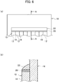
- Fig. 6 is a view for explaining the welding step (S12)
- Fig. 6 (a) is an overall schematic view
- Fig. 6 (b) is a schematic view of a cross section taken along the direction A-A of Fig. 6(a) .
- the welding region of the diffusion bonded structure 10 in which the buffer layer 20 is formed is bonded to the another part 16 by the normal welding from above the buffer layer 20.
- a welding layer 22 is formed by this welding and the diffusion bonded structure 10 is bonded to the another part 16 by welding.
- a general welding method such as arc welding, shielded metal arc welding (SMAW), TIG welding, or MIG welding can be used.
- arc welding can be performed by forming multiple welding beads by shielded metal arc welding (SMAW) with high heat input or the like.
- SMAW shielded metal arc welding
- the same kind of material as the metal parts 12 or a material different from the metal parts 12 may be used as a welding material.
- a metal material with the same alloy composition as the metal parts 12 can be used as the welding material.
- the buffer layer 20 absorbs and buffers the strain caused by the normal welding and cracking in the diffusion bonded joints 14 is thus suppressed.
- the strain curve (S w ) of the strain caused by the normal welding is located below the ductility curve (E i ) of the buffer layer 20.
- the buffer layer 20 thus absorbs and buffers the strain caused by the normal welding even when the ductility of the diffusion bonded joints 14 decreases in the normal welding, and cracking in the diffusion bonded joints 14 is thereby prevented.
- the above welding method of the diffusion bonded structure 10 may be used also when the diffusion bonded structure 10 and the another part 16 are fusion welded by a joint welding method.
- Such fusion welding by the joint welding method can be patch welding, butt welding, fillet welding, or lap welding.
- the above welding method of the diffusion bonded structure 10 can be used in a joint welding method in which the parts are fuse welded to form a shape with a high degree of constraint such as patch welding or the like.
- a reaction container used in a heat exchange reactor handles highly corrosive fluid at high temperature and high pressure and is thus a high stiffness reaction container formed of a thick plate of Ni alloy parts.
- This reaction container is formed of a diffusion bonded structure formed by diffusion bonding the Ni alloy parts. When this reaction container is to be attached to a thick plate flange, the reaction container is patch welded to the flange.
- the welding method includes the buffer layer formation step of forming the buffer layer in the welding region including the diffusion bonded joints of the diffusion bonded structure formed by diffusion bonding the metal parts to each other, the buffer layer having higher ductility than the diffusion bonded joints, and the welding step of bonding the welding region of the diffusion bonded structure in which the buffer layer is formed to the another part by performing fusion welding from above the buffer layer. Accordingly, the buffer layer absorbs and buffers the strain caused by the fusion welding and cracking in the diffusion bonded joints can be thereby suppressed.
- a diffusion bonded structure was formed by diffusion bonding multiple Ni alloy parts.
- the Ni alloy parts were made of Haynes alloy 230.
- the diffusion bonded structure included a diffusion bonded joint between each pair of adjacent Ni alloy parts.
- a welding region including the diffusion bonded joints of the diffusion bonded structure and a metal block were arc welded to form a welding layer and the diffusion bonded structure was thus bonded to the metal block.
- a material with the same alloy composition as Haynes alloy 230 was used as a welding material.
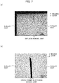
- Fig. 7 includes pictures depicting observation results obtained by using the optical microscope after the arc welding in the welding method of the comparative example, Fig. 7(a) is a picture depicting a cross section of the diffusion bonded joints directly below the welding layer, and Fig. 7 (b) is an enlarged picture of a crack depicted in Fig. 7(a) .
- a penetrating crack extending several millimeters or more was formed in the diffusion bonded joints directly below the welding layer. Note that no crack was formed in the welding layer and the Ni alloy parts which were the base metal.
- a welding method of an example is described.
- the same diffusion bondedstructure as one used in the welding method of the comparative example was used as a diffusion bonded structure.
- a buffer layer was formed in a welding region including diffusion bonded joints of the diffusion bonded structure by overlay welding.
- TIG welding was used as the overlay welding.
- the welding conditions were such that arc voltage was 12 V, welding current was 80A, and welding rate was 100 mm/min.
- the overlay welding was performed while using a filler.
- a material with the same alloy composition as Haynes alloy 230 was used as the filer.
- Two passes of the overlay welding were performed and a buffer layer formed of two overlay layers was formed. The thickness of the buffer layer was 2.5 mm. After the formation of the buffer layer, ultrasonic flaw inspection and penetrant inspection were performed to check that no crack was formed in the buffer layer and the diffusion bonded joints directly below the buffer layer.
- the welding region in which the buffer layer was formed and a metal block were arc welded to each other from above the buffer layer to form a welding layer and the diffusion bonded structure was thus bonded to the metal block.
- the arc welding was the same as the welding method in the comparative example. A material with the same alloy composition as Haynes alloy 230 was used as a welding material. After the arc welding, the welding layer was removed and the buffer layer and the diffusion bonded joints directly below the buffer layer were observed by using the optical microscope.
- Fig. 8 includes pictures depicting observation results obtained by using the optical microscope after the arc welding in the welding method of the example, Fig.8(a) is a picture depicting the diffusion bonded joints directly below the buffer layer, and Fig. 8 (b) is an enlarged picture of Fig. 8(a) . No formation of crack was confirmed in the buffer layer and the diffusion bonded joints directly below the buffer layer. From these results, it is found that forming the buffer layer in the welding region including the diffusion bonded joints and performing the arc welding from above the buffer layer causes the buffer layer to absorb and buffer the strain caused by the arc welding and cracking in the diffusion bonded joint can be thereby suppressed.
- the buffer layer absorbs and buffers the strain caused by the fusion welding and cracking in the diffusion bonded joints of the diffusion bonded structure can be thereby suppressed. Accordingly, the present disclosure is useful in a reaction container of a heat exchange reactor and the like.
Landscapes
- Engineering & Computer Science (AREA)
- Mechanical Engineering (AREA)
- Physics & Mathematics (AREA)
- Plasma & Fusion (AREA)
- Chemical & Material Sciences (AREA)
- Materials Engineering (AREA)
- Pressure Welding/Diffusion-Bonding (AREA)
- Arc Welding In General (AREA)
Abstract
Description
- The present disclosure relates to a welding method of a diffusion bonded structure and particularly relates to a welding method of a diffusion bonded structure in which the diffusion bonded structure formed by diffusion bonding metal parts to each other is bonded to another part by fusion welding.
- In a heat exchanger, a heat exchange reactor, a microchannel apparatus, or the like, components made of diffusion bonded bodies formed by diffusion bonding metal parts to each other are used. When such a diffusion bonded structure is combined with another part to form an assembly, bonding by welding is performed (see Non Patent Literature 1)
- [NPL 1] Fabrication and design aspects of high-temperature compact diffusion bonded heat exchangers, Nuclear Engineering and Design 249 (2012) 49-56
- When a diffusion bonded structure formed by diffusion bonding metal parts to each other is bonded to another part by fusion welding, ductility of a diffusion bonded joint of the diffusion bonded structure decreases more at high temperature in the fusing welding than that of the metal parts which are the base metal. Cracking sensitivity in the diffusion bonded joint of the diffusion bonded structure thereby is higher than that in the metal parts. Accordingly, strain caused by the fusion welding may cause cracking in the diffusion bonded joint.
- In view of this, an object of the present disclosure is to provide a welding method of a diffusion bonded structure which can suppress cracking in a diffusion bonded joint when a diffusion bonded structure formed by diffusion bonding metal parts to each other is bonded to another part by fusion welding.
- A welding method of a diffusion bonded structure according to the present disclosure is a welding method of a diffusion bonded structure in which the diffusion bonded structure formed by diffusion bonding metal parts to each other is bonded to another part by fusion welding, the welding method including a buffer layer forming step of forming a buffer layer in a welding region including a diffusion bonded joint of the diffusion bonded structure, the buffer layer having higher ductility than the diffusion bonded joint, and a welding step of bonding the welding region in which the buffer layer is formed to the another part by performing the fusion welding from above the buffer layer.
- In the welding method of a diffusion bonded structure according to the present disclosure, in the buffer layer forming step, the buffer layer may be formed by overlay welding.
- In the welding method of a diffusion bonded structure according to the present disclosure, in the buffer layer forming step, the buffer layer may be formed by any one of processes of powder sintering, ultrasonic welding, friction welding, friction surfacing, friction stir welding, friction stir processing, diffusion bonding, brazing, magnetic pulse welding, and explosive welding.
- In the welding method of a diffusion bonded structure according to the present disclosure, the diffusion bonded structure may be fusion welded to the another part by a joint welding method.
- In the welding method of a diffusion bonded structure according to the present disclosure, the fusion welding by a joint welding method may be patch welding, butt welding, fillet welding, or lap welding.
- According to the above configurations, since the buffer layer absorbs and buffers strain caused by the fusion welding, cracking in the diffusion bonded joint of the diffusion bonded structure can be suppressed.
-
- [
Fig. 1] Fig. 1 is a flowchart illustrating a configuration of a welding method of a diffusion bonded structure in an embodiment of the present disclosure. - [
Fig. 2] Fig. 2 is a view for explaining a buffer layer formation step in the embodiment of the present disclosure. - [
Fig. 3] Fig. 3 is a graph for explaining ductility of diffusion bonded joints and ductility of metal parts which are base metal in the embodiment of the present disclosure. - [
Fig. 4] Fig. 4 is a graph for explaining the ductility of the diffusion bonded joints, the ductility of the metal parts which are the base metal, and ductility of a buffer layer in the embodiment of the present disclosure. - [
Fig. 5] Fig. 5 is a graph illustrating relationships between the ductility of the diffusion bonded joints and strain occurring in buffer layer formation in the embodiment of the present disclosure. - [
Fig. 6] Fig. 6 is a view for explaining a welding step in the embodiment of the present disclosure. - [
Fig. 7] Fig. 7 includes pictures depicting observation results obtained by using an optical microscope after arc welding in a welding method of a comparative example in the embodiment of the present disclosure. - [
Fig. 8] Fig. 8 includes pictures depicting observation results obtained by using the optical microscope after arc welding in a welding method of an example in the embodiment of the present disclosure. - An embodiment of the present disclosure is described below in detail by using the drawings.
Fig. 1 is a flowchart illustrating a configuration of a welding method of a diffusion bonded structure. The welding method of a diffusion bonded structure includes a buffer layer formation step (S10) and a welding step (S12). - The buffer layer formation step (S10) is a step of forming a buffer layer in a welding region including diffusion bonded joints of a diffusion bonded structure formed by diffusion bonding metal parts to each other, the buffer layer having higher ductility than the diffusion bonded joints.
Fig. 2 is a view for explaining the buffer layer formation step (S10),Fig. 2 (a) is an overall schematic view, andFig. 2(b) is a schematic view of a cross section taken along the direction A-A inFig. 2(a) . - The diffusion bonded
structure 10 is described. The diffusion bondedstructure 10 is formed by diffusion bondingmetal parts 12 to each other. Themetal parts 12 are made of a Ni alloy such as Inconel 625, Inconel 617, or Haynes alloy 230, a stainless steel such as an austenitic stainless steel, or the like. The diffusion bondedstructure 10 is formed by a general diffusion bonding method for a metal material. The diffusion bondedstructure 10 includes diffusion bondedjoints 14 where themetal parts 12 are diffusion bonded to each other. - When the diffusion bonded
structure 10 is bonded to anotherpart 16 by fusion welding (hereafter also referred to as "normal welding") in the welding step (S12) to be described later, the diffusion bondedjoints 14 are heated to high temperature in the normal welding. The ductility of the diffusion bondedjoints 14 tends to decrease at high temperature more than the ductility of themetal parts 12 which are base metal. Since the diffusion bondedjoints 14 are heated to high temperature in the normal welding, the ductility of the diffusion bondedjoints 14 decreases.Fig. 3 is a graph for explaining the ductility of the diffusion bondedjoints 14 and the ductility of themetal parts 12 which are the base metal. InFig. 3 , the horizontal axis represents temperature, the vertical axis represents ductility, the solid line illustrates a ductility curve (Edb) of the diffusion bondedjoints 14, and the two-dot chain line illustrates a ductility curve (Eb) of themetal parts 12. The ductility of the diffusion bondedjoints 14 decreases more than the ductility of themetal parts 12 which are the base metal in a high temperature region. When themetal parts 12 are made of a Ni alloy or a stainless steel, the temperature region in which the ductility of the diffusion bondedjoints 14 decreases is generally a temperature region around 1000°C. - In
Fig. 3 , the broken line illustrates a strain curve (Sw) of strain caused by the normal welding in the case where the diffusion bondedstructure 10 is bonded to theanother part 16 by the normal welding. When the diffusion bondedstructure 10 is bonded to theanother part 16 by the normal welding, deformation is constrained and the strain caused by the normal welding is thus large. In a temperature region in which the strain curve (Sw) intersects the ductility curve (Edb) of the diffusion bondedjoints 14 and exceeds the ductility curve (Edb), ductility dip cracking which is one type of hot cracking may occur in the diffusion bondedjoints 14. The larger the constraint in the normal welding is, the more likely the ductility dip cracking in the diffusion bondedjoints 14 is to occur. Such welding with large constraint includes, for example, patch welding and the like. - A
buffer layer 20 is formed as a welding region including the diffusion bondedjoints 14 of the diffusion bondedstructure 10. Thebuffer layer 20 has higher ductility than the diffusion bondedjoints 14. Thebuffer layer 20 has a function of absorbing and buffering the strain caused by the normal welding in the welding step (S12) to be described later. -
Fig. 4 is a graph for explaining the ductility of the diffusion bondedjoints 14, the ductility of themetal parts 12 which are the base metal, and the ductility of thebuffer layer 20. InFig. 4 , the horizontal axis represents temperature, the vertical axis represents ductility, the bold solid line illustrates the ductility curve (Edb) of the diffusion bondedjoints 14, the two-dot chain line illustrates the ductility curve (Eb) of themetal parts 12 which are the base metal, and the thin solid line illustrates a ductility curve (Ei) of thebuffer layer 20. Moreover, inFig. 4 , the broken line illustrates the strain curve (Sw) of the strain caused by the normal welding in the case where the diffusion bondedstructure 10 is bonded to theanother part 16 by the normal welding. - The ductility of the
buffer layer 20 is higher than that of the diffusion bondedjoints 14 at high temperature. As a result, the ductility curve (Ei) of thebuffer layer 20 does not intersect the strain curve (Sw) and is located above the strain curve (Sw). Thebuffer layer 20 thus absorbs and buffers the strain caused by the normal welding when the diffusion bondedjoints 14 provided with thebuffer layer 20 is bonded to theanother part 16 by the normal welding in the welding step (S12) to be described later, and cracking in the diffusion bondedjoints 14 is thereby suppressed. The thickness of thebuffer layer 20 varies depending on the metal material forming thebuffer layer 20, constraint conditions of the normal welding, and the like and is, for example, about 1 mm to 10 mm. - Since the
buffer layer 20 is formed in the welding region including the diffusion bondedjoints 14 of the diffusion bondedstructure 10 and there is almost no constraint of theanother part 16 in buffer layer formation, thebuffer layer 20 can easily deform. Accordingly, the constraint in the buffer layer formation is smaller than the constraint in the normal welding in the welding step (S12) to be described later and the strain caused by the buffer layer formation can be thus made smaller than the strain caused by the normal welding. -
Fig. 5 is a graph illustrating relationships between the ductility of the diffusion bondedjoints 14 and the strain caused by the buffer layer formation. InFig. 5 , the horizontal axis represents temperature, the vertical axis represents ductility, the bold solid line illustrates the ductility curve (Edb) of the diffusion bondedjoints 14, the two-dot chain line illustrates the ductility curve (Eb) of themetal parts 12 which are the base metal, and the thin solid line illustrates the ductility curve (Ei) of thebuffer layer 20. Moreover, inFig. 5 , the broken lines illustrate the strain curve (Sc) of the strain caused by the buffer layer formation and the strain curve (Sw) of the strain caused by the normal welding. - Since the constraint in the buffer layer formation is smaller than that in the normal welding in the welding step (S12) to be described later, the strain curve (Sc) is located below the strain curve (Sw). As a result, the strain curve (Sc) does not intersect the ductility curve (Edb) of the diffusion bonded
joints 14 and is located below the ductility curve (Edb) . Cracking in the diffusion bondedjoints 14 can be thus suppressed in the buffer layer formation. - The
buffer layer 20 may be made of the same kind of material as themetal parts 12 which are the base metal. Thebuffer layer 20 being made of the same kind of material as themetal parts 12 can suppress local deformation due to strength distribution, galvanic corrosion, and contamination from an interface between different materials (mixing of foreign objects) . For example, when themetal parts 12 are made of a Ni alloy, thebuffer layer 20 can be made of the Ni alloy. Moreover, thebuffer layer 20 may be made of a metal material with the same alloy composition as themetal parts 12. For example, when themetal parts 12 are made of Haynes alloy 230, thebuffer layer 20 can be made of a metal material with the same alloy composition as Haynes alloy 230. - The
buffer layer 20 may be made of a material different from themetal parts 12 which are the base metal. When thebuffer layer 20 is to be made of a material different from themetal parts 12, a soft material with lower yield stress and higher ductility than themetal parts 12 may be used for thebuffer layer 20. Using such soft material can cause the strain caused by the normal welding to be concentrated in thebuffer layer 20 and also prevents the stress equal to or larger than the yield stress of thebuffer layer 20 from being applied to the diffusion bonded joints 14. A cracking prevention effect equal to or higher than that in the case where thebuffer layer 20 is made of the same kind of material as themetal parts 12 can be thereby obtained even when the thickness of thebuffer layer 20 is made smaller than that in the case where thebuffer layer 20 is made of the same kind of material as themetal parts 12. - As a method of forming the
buffer layer 20, a formation method with lower constraint may be used to further reduce the strain caused by the buffer layer formation. As such a method of forming thebuffer layer 20, overlay welding (buttering) may be used. The overlay welding (buttering) is a method of overlaying weld metal to be deposited in the welding region including the diffusion bonded joints 14. Accordingly, there is almost no constraint and the strain caused by the buffer layer formation can be further reduced. Shielded metal arc welding (SMAW), MIG welding, TIG welding, resistance welding, laser welding, electron beam welding, thermal spraying, or the like can be performed as a process used in the overlay welding. The same kind of material as themetal parts 12 or a material different from themetal parts 12 can be used as a welding material. A metal material with the same alloy composition as themetal parts 12 can be used as the welding material. When thebuffer layer 20 is to be formed by the overlay welding, thebuffer layer 20 may be formed by forming a welding bead in one pass or two or more. Moreover, the buffer layer may be formed without using the welding material, by locally melting and solidifying a surface portion without using a filler. In addition to the overlay welding, butt welding of thin plate metal pieces, lap welding of thin plate metal pieces, and the like can be used as the above method of forming thebuffer layer 20. - As a method of forming the
buffer layer 20, solid state bonding in which strain due to temperature change is small and in which strain caused by melting and solidification does not occur may be used to further reduce the strain caused by the formation of thebuffer layer 20. As such a method of forming thebuffer layer 20, powder sintering, ultrasonic welding, friction welding, friction surfacing, friction stir welding, friction stir processing, diffusion bonding, brazing, magnetic pulse welding, explosive welding, and the like can be used. - In the method of forming the
buffer layer 20, a formation method with small constraint and a solid state bonding with small strain may be used in combination. As such a method of forming thebuffer layer 20, for example, the overlay welding may be performed by friction surfacing with low heat input. This further reduces the strain caused by the buffer layer formation and cracking in the diffusion bondedjoints 14 can be thus further suppressed. - The welding step (S12) is a step of bonding the welding region of the diffusion bonded
structure 10 in which thebuffer layer 20 is formed to the anotherpart 16 by performing fusion welding from above thebuffer layer 20.Fig. 6 is a view for explaining the welding step (S12),Fig. 6 (a) is an overall schematic view, andFig. 6 (b) is a schematic view of a cross section taken along the direction A-A ofFig. 6(a) . - The welding region of the diffusion bonded
structure 10 in which thebuffer layer 20 is formed is bonded to the anotherpart 16 by the normal welding from above thebuffer layer 20. Awelding layer 22 is formed by this welding and the diffusion bondedstructure 10 is bonded to the anotherpart 16 by welding. As the normal welding, a general welding method such as arc welding, shielded metal arc welding (SMAW), TIG welding, or MIG welding can be used. For example, arc welding can be performed by forming multiple welding beads by shielded metal arc welding (SMAW) with high heat input or the like. The same kind of material as themetal parts 12 or a material different from themetal parts 12 may be used as a welding material. A metal material with the same alloy composition as themetal parts 12 can be used as the welding material. - Even when the diffusion bonded
structure 10 is bonded to the anotherpart 16 by the normal welding and is constrained, thebuffer layer 20 absorbs and buffers the strain caused by the normal welding and cracking in the diffusion bondedjoints 14 is thus suppressed. In detail, as described inFig. 4 , the strain curve (Sw) of the strain caused by the normal welding is located below the ductility curve (Ei) of thebuffer layer 20. Thebuffer layer 20 thus absorbs and buffers the strain caused by the normal welding even when the ductility of the diffusion bondedjoints 14 decreases in the normal welding, and cracking in the diffusion bondedjoints 14 is thereby prevented. - The above welding method of the diffusion bonded
structure 10 may be used also when the diffusion bondedstructure 10 and the anotherpart 16 are fusion welded by a joint welding method. Such fusion welding by the joint welding method can be patch welding, butt welding, fillet welding, or lap welding. Moreover, the above welding method of the diffusion bondedstructure 10 can be used in a joint welding method in which the parts are fuse welded to form a shape with a high degree of constraint such as patch welding or the like. For example, a reaction container used in a heat exchange reactor handles highly corrosive fluid at high temperature and high pressure and is thus a high stiffness reaction container formed of a thick plate of Ni alloy parts. This reaction container is formed of a diffusion bonded structure formed by diffusion bonding the Ni alloy parts. When this reaction container is to be attached to a thick plate flange, the reaction container is patch welded to the flange. - Since the stiffness of the reaction container and the stiffness of the flange are both high and these parts are patch welded to each other, strain caused by normal welding is large. Even in the patch welding with large constraint as described above, cracking in the diffusion bonded joints of the reaction container can be suppressed by forming the buffer layer in the welding region including the diffusion bonded s of the reaction container and then bonding the flange and the reaction container by performing the normal welding from above the buffer layer.
- As described above, according to the above configuration, the welding method includes the buffer layer formation step of forming the buffer layer in the welding region including the diffusion bonded joints of the diffusion bonded structure formed by diffusion bonding the metal parts to each other, the buffer layer having higher ductility than the diffusion bonded joints, and the welding step of bonding the welding region of the diffusion bonded structure in which the buffer layer is formed to the another part by performing fusion welding from above the buffer layer. Accordingly, the buffer layer absorbs and buffers the strain caused by the fusion welding and cracking in the diffusion bonded joints can be thereby suppressed.
- A welding test of the diffusion bonded structure was performed.
- First, a welding method of a comparative example is described. A diffusion bonded structure was formed by diffusion bonding multiple Ni alloy parts. The Ni alloy parts were made of Haynes alloy 230. The diffusion bonded structure included a diffusion bonded joint between each pair of adjacent Ni alloy parts. In the welding method of the comparative example, a welding region including the diffusion bonded joints of the diffusion bonded structure and a metal block were arc welded to form a welding layer and the diffusion bonded structure was thus bonded to the metal block. A material with the same alloy composition as Haynes alloy 230 was used as a welding material.
- After the arc welding, the diffusion bonded joints directly below the welding layer was observed by using an optical microscope.
Fig. 7 includes pictures depicting observation results obtained by using the optical microscope after the arc welding in the welding method of the comparative example,Fig. 7(a) is a picture depicting a cross section of the diffusion bonded joints directly below the welding layer, andFig. 7 (b) is an enlarged picture of a crack depicted inFig. 7(a) . A penetrating crack extending several millimeters or more was formed in the diffusion bonded joints directly below the welding layer. Note that no crack was formed in the welding layer and the Ni alloy parts which were the base metal. - Next, a welding method of an example is described. The same diffusion bondedstructure as one used in the welding method of the comparative example was used as a diffusion bonded structure. First, a buffer layer was formed in a welding region including diffusion bonded joints of the diffusion bonded structure by overlay welding. TIG welding was used as the overlay welding. The welding conditions were such that arc voltage was 12 V, welding current was 80A, and welding rate was 100 mm/min. The overlay welding was performed while using a filler. A material with the same alloy composition as Haynes alloy 230 was used as the filer. Two passes of the overlay welding were performed and a buffer layer formed of two overlay layers was formed. The thickness of the buffer layer was 2.5 mm. After the formation of the buffer layer, ultrasonic flaw inspection and penetrant inspection were performed to check that no crack was formed in the buffer layer and the diffusion bonded joints directly below the buffer layer.
- Next, the welding region in which the buffer layer was formed and a metal block were arc welded to each other from above the buffer layer to form a welding layer and the diffusion bonded structure was thus bonded to the metal block. The arc welding was the same as the welding method in the comparative example. A material with the same alloy composition as Haynes alloy 230 was used as a welding material. After the arc welding, the welding layer was removed and the buffer layer and the diffusion bonded joints directly below the buffer layer were observed by using the optical microscope.
-
Fig. 8 includes pictures depicting observation results obtained by using the optical microscope after the arc welding in the welding method of the example,Fig.8(a) is a picture depicting the diffusion bonded joints directly below the buffer layer, andFig. 8 (b) is an enlarged picture ofFig. 8(a) . No formation of crack was confirmed in the buffer layer and the diffusion bonded joints directly below the buffer layer. From these results, it is found that forming the buffer layer in the welding region including the diffusion bonded joints and performing the arc welding from above the buffer layer causes the buffer layer to absorb and buffer the strain caused by the arc welding and cracking in the diffusion bonded joint can be thereby suppressed. - In the present disclosure, the buffer layer absorbs and buffers the strain caused by the fusion welding and cracking in the diffusion bonded joints of the diffusion bonded structure can be thereby suppressed. Accordingly, the present disclosure is useful in a reaction container of a heat exchange reactor and the like.
Claims (5)
- A welding method of a diffusion bonded structure in which the diffusion bonded structure formed by diffusion bonding metal parts to each other is bonded to another part by fusion welding, the welding method comprising:a buffer layer forming step of forming a buffer layer in a welding region including a diffusion bonded joint of the diffusion bonded structure, the buffer layer having higher ductility than the diffusion bonded joint; anda welding step of bonding the welding region in which the buffer layer is formed to the another part by performing the fusion welding from above the buffer layer.
- The welding method of a diffusion bonded structure according to claim 1, wherein, in the buffer layer forming step, the buffer layer is formed by overlay welding.
- The welding method of a diffusion bonded structure according to claim 1, wherein, in the buffer layer forming step, the buffer layer is formed by any one of processes of powder sintering, ultrasonic welding, friction welding, friction surfacing, friction stir welding, friction stir processing, diffusion bonding, brazing, magnetic pulse welding, and explosive welding.
- The welding method of a diffusion bonded structure according to any one of claims 1 to 3, wherein the diffusion bonded structure is fusion welded to the another part by a joint welding method.
- The welding method of a diffusion bonded structure according to claim 4, wherein the fusion welding by a joint welding method is patch welding, butt welding, fillet welding, or lap welding.
Applications Claiming Priority (2)
| Application Number | Priority Date | Filing Date | Title |
|---|---|---|---|
| JP2017010001A JP6897110B2 (en) | 2017-01-24 | 2017-01-24 | Welding method for diffusion joints |
| PCT/JP2018/001338 WO2018139327A1 (en) | 2017-01-24 | 2018-01-18 | Diffusion-bonded body welding method |
Publications (3)
| Publication Number | Publication Date |
|---|---|
| EP3575027A1 true EP3575027A1 (en) | 2019-12-04 |
| EP3575027A4 EP3575027A4 (en) | 2020-11-25 |
| EP3575027B1 EP3575027B1 (en) | 2022-02-23 |
Family
ID=62978900
Family Applications (1)
| Application Number | Title | Priority Date | Filing Date |
|---|---|---|---|
| EP18745129.9A Active EP3575027B1 (en) | 2017-01-24 | 2018-01-18 | Diffusion-bonded body welding method |
Country Status (8)
| Country | Link |
|---|---|
| US (1) | US11498145B2 (en) |
| EP (1) | EP3575027B1 (en) |
| JP (1) | JP6897110B2 (en) |
| KR (1) | KR102232051B1 (en) |
| CN (1) | CN110198802B (en) |
| CA (1) | CA3051048C (en) |
| DK (1) | DK3575027T3 (en) |
| WO (1) | WO2018139327A1 (en) |
Families Citing this family (1)
| Publication number | Priority date | Publication date | Assignee | Title |
|---|---|---|---|---|
| JP7599967B2 (en) | 2021-01-21 | 2024-12-16 | プライムプラネットエナジー&ソリューションズ株式会社 | Terminal parts, secondary batteries and battery packs |
Family Cites Families (17)
| Publication number | Priority date | Publication date | Assignee | Title |
|---|---|---|---|---|
| JPS607591B2 (en) * | 1979-07-31 | 1985-02-26 | 三菱重工業株式会社 | Clad pipe production method |
| SE447804B (en) * | 1983-04-20 | 1986-12-15 | Kuroki Kogyosho Kk | PROCEDURE FOR MANUFACTURING COMPOSITE STALLS |
| JPS6149789A (en) * | 1984-08-15 | 1986-03-11 | Nippon Kokan Kk <Nkk> | Circumferential welding method for clad steel pipes |
| JPH01103966A (en) | 1987-10-16 | 1989-04-21 | Toshiba Corp | Ceramic-metal bonded body |
| JPH01210171A (en) * | 1988-02-15 | 1989-08-23 | Nippon Steel Corp | Method for welding stainless steel or nickel alloy and carbon steel |
| JPH0724577A (en) * | 1993-07-13 | 1995-01-27 | Kubota Corp | Butt welding method for clad pipes |
| JP2007050439A (en) | 2005-08-19 | 2007-03-01 | Mitsubishi Heavy Ind Ltd | Method for joining multilayered tube, and multilayered tube |
| US20070221705A1 (en) | 2006-03-24 | 2007-09-27 | Arnett Michael D | Buttered welding of superalloys |
| JP5304392B2 (en) * | 2009-03-31 | 2013-10-02 | 株式会社Ihi | Dissimilar joint structure and manufacturing method thereof |
| CN101633074A (en) * | 2009-07-16 | 2010-01-27 | 西安交通大学 | Welding method of girth weld of inner cladding thin-walled stainless steel composite tube |
| KR101973576B1 (en) | 2010-03-02 | 2019-04-29 | 벨로시스, 인코포레이티드 | Welded, laminated apparatus, methods of making, and methods of using the apparatus |
| WO2015068853A1 (en) | 2013-11-11 | 2015-05-14 | 新日鐵住金株式会社 | Metal bonding structure, metal bonding method, and metal bonding material using metal nanoparticles |
| JP6384894B2 (en) | 2013-11-11 | 2018-09-05 | 新日鐵住金株式会社 | Metal bonding structure, metal bonding method and metal bonding material using metal nanoparticles |
| JP6149789B2 (en) * | 2014-04-23 | 2017-06-21 | Jfeスチール株式会社 | Steel continuous casting method |
| US10260370B2 (en) | 2014-12-10 | 2019-04-16 | General Electric Company | Nanostructured ferritic alloy components and related articles |
| CN105127562B (en) * | 2015-09-30 | 2017-04-12 | 青岛兰石重型机械设备有限公司 | Method for welding welded joint between stainless steel composite plate and austenitic stainless steel |
| CN107030359B (en) * | 2017-06-01 | 2020-01-14 | 中国石油大学(华东) | Bimetal mechanical composite pipe welding process |
-
2017
- 2017-01-24 JP JP2017010001A patent/JP6897110B2/en active Active
-
2018
- 2018-01-18 WO PCT/JP2018/001338 patent/WO2018139327A1/en not_active Ceased
- 2018-01-18 EP EP18745129.9A patent/EP3575027B1/en active Active
- 2018-01-18 KR KR1020197023503A patent/KR102232051B1/en active Active
- 2018-01-18 CN CN201880007798.9A patent/CN110198802B/en active Active
- 2018-01-18 DK DK18745129.9T patent/DK3575027T3/en active
- 2018-01-18 CA CA3051048A patent/CA3051048C/en active Active
-
2019
- 2019-07-18 US US16/515,391 patent/US11498145B2/en active Active
Also Published As
| Publication number | Publication date |
|---|---|
| JP6897110B2 (en) | 2021-06-30 |
| US11498145B2 (en) | 2022-11-15 |
| DK3575027T3 (en) | 2022-04-19 |
| CA3051048C (en) | 2021-05-11 |
| JP2018118261A (en) | 2018-08-02 |
| EP3575027B1 (en) | 2022-02-23 |
| KR102232051B1 (en) | 2021-03-24 |
| CN110198802A (en) | 2019-09-03 |
| CN110198802B (en) | 2021-09-24 |
| EP3575027A4 (en) | 2020-11-25 |
| US20190337078A1 (en) | 2019-11-07 |
| CA3051048A1 (en) | 2018-08-02 |
| WO2018139327A1 (en) | 2018-08-02 |
| KR20190107073A (en) | 2019-09-18 |
Similar Documents
| Publication | Publication Date | Title |
|---|---|---|
| US10927869B2 (en) | Welding methods and welded joints for joining high-strength aluminum alloys | |
| JP6461056B2 (en) | Arc spot welding method for joining dissimilar materials, joining auxiliary member, and dissimilar material welding joint | |
| Dutra et al. | Metallurgical characterization of the 5083H116 aluminum alloy welded with the cold metal transfer process and two different wire-electrodes (5183 and 5087) | |
| Fink et al. | Welding of nickel-based alloy 617 using modified dip arc processes | |
| EP3587614B1 (en) | Laser brazing method and production method for lap joint member | |
| Frank | Flux-free laser joining of aluminum and galvanized steel | |
| Devendranath Ramkumar et al. | Effect of filler metals on the weldability and mechanical properties of multi-pass PCGTA weldments of AISI 316L | |
| Shahid et al. | Mechanical and microstuctural analysis of dissimilar metal welds | |
| JP4915251B2 (en) | Clad welded structure of low alloy steel base metal | |
| US11498145B2 (en) | Welding method of diffusion bonded structure | |
| KR102061470B1 (en) | MIG brazing method, manufacturing method of overlap joint member, and overlap joint member | |
| Swierczynska et al. | The effect of welding conditions on mechanical properties of superduplex stainless steel welded joints | |
| JP2017080791A (en) | Weld conjugant of ferrous metal/aluminum-based metal, and method for production thereof | |
| WO2016093099A1 (en) | Flux-cored wire, and method for manufacturing welded joint | |
| CA3006950A1 (en) | Process of butt-welding a laminated item, and an assembly comprising a butt-welded laminated item | |
| Kiser et al. | Nickel alloy welding requirements for nuclear service | |
| JP3232033B2 (en) | Welding method for Fe-Ni low thermal expansion alloy | |
| Katayama et al. | Evaluation of weldability of nickel-base alloy weld materials with high chromium content | |
| JP2005000989A (en) | Method of bonding iron based material and aluminum based material, and bonding joint | |
| Delpero et al. | Mechanical Integrity and Weld Characterization of FCAW and GTAW Joints on API 5L CO2 Fire Suppression Pipes | |
| Singh et al. | Mechanical and Microstructural Properties of GMAW Welded Ferritic AISI 1080 Carbon Steel (UNS G10800) | |
| Devletian et al. | Flux cored arc welding of CuNi 90/10 piping with CuNi 70/30 filler metal | |
| Padmanabham et al. | A Comparision of Interface Characteristics and Mechanical Properties of Aluminium-Steel Joints Made by Pulsed-MIG and Cold Metal Transfer (CMT) Processes | |
| Adamiec et al. | CMT robotized welding of thin-walled joints made of 7xxx series aluminium alloy | |
| Westin et al. | Stainless Steel Bismuth Free Flux-cored Wires for High Temperature Applications |
Legal Events
| Date | Code | Title | Description |
|---|---|---|---|
| STAA | Information on the status of an ep patent application or granted ep patent |
Free format text: STATUS: THE INTERNATIONAL PUBLICATION HAS BEEN MADE |
|
| PUAI | Public reference made under article 153(3) epc to a published international application that has entered the european phase |
Free format text: ORIGINAL CODE: 0009012 |
|
| STAA | Information on the status of an ep patent application or granted ep patent |
Free format text: STATUS: REQUEST FOR EXAMINATION WAS MADE |
|
| 17P | Request for examination filed |
Effective date: 20190723 |
|
| AK | Designated contracting states |
Kind code of ref document: A1 Designated state(s): AL AT BE BG CH CY CZ DE DK EE ES FI FR GB GR HR HU IE IS IT LI LT LU LV MC MK MT NL NO PL PT RO RS SE SI SK SM TR |
|
| AX | Request for extension of the european patent |
Extension state: BA ME |
|
| DAV | Request for validation of the european patent (deleted) | ||
| DAX | Request for extension of the european patent (deleted) | ||
| A4 | Supplementary search report drawn up and despatched |
Effective date: 20201022 |
|
| RIC1 | Information provided on ipc code assigned before grant |
Ipc: B23K 9/23 20060101AFI20201016BHEP Ipc: B23K 20/02 20060101ALN20201016BHEP Ipc: B23K 9/04 20060101ALI20201016BHEP Ipc: B23K 20/00 20060101ALI20201016BHEP Ipc: B23K 9/235 20060101ALI20201016BHEP |
|
| RIC1 | Information provided on ipc code assigned before grant |
Ipc: B23K 20/02 20060101ALN20210910BHEP Ipc: B23K 9/235 20060101ALI20210910BHEP Ipc: B23K 20/00 20060101ALI20210910BHEP Ipc: B23K 9/04 20060101ALI20210910BHEP Ipc: B23K 9/23 20060101AFI20210910BHEP |
|
| GRAP | Despatch of communication of intention to grant a patent |
Free format text: ORIGINAL CODE: EPIDOSNIGR1 |
|
| STAA | Information on the status of an ep patent application or granted ep patent |
Free format text: STATUS: GRANT OF PATENT IS INTENDED |
|
| RIC1 | Information provided on ipc code assigned before grant |
Ipc: B23K 20/02 20060101ALN20210920BHEP Ipc: B23K 9/235 20060101ALI20210920BHEP Ipc: B23K 20/00 20060101ALI20210920BHEP Ipc: B23K 9/04 20060101ALI20210920BHEP Ipc: B23K 9/23 20060101AFI20210920BHEP |
|
| RIC1 | Information provided on ipc code assigned before grant |
Ipc: B23K 20/02 20060101ALN20210930BHEP Ipc: B23K 9/235 20060101ALI20210930BHEP Ipc: B23K 20/00 20060101ALI20210930BHEP Ipc: B23K 9/04 20060101ALI20210930BHEP Ipc: B23K 9/23 20060101AFI20210930BHEP |
|
| RIC1 | Information provided on ipc code assigned before grant |
Ipc: B23K 20/02 20060101ALN20211005BHEP Ipc: B23K 9/235 20060101ALI20211005BHEP Ipc: B23K 20/00 20060101ALI20211005BHEP Ipc: B23K 9/04 20060101ALI20211005BHEP Ipc: B23K 9/23 20060101AFI20211005BHEP |
|
| INTG | Intention to grant announced |
Effective date: 20211021 |
|
| GRAS | Grant fee paid |
Free format text: ORIGINAL CODE: EPIDOSNIGR3 |
|
| GRAA | (expected) grant |
Free format text: ORIGINAL CODE: 0009210 |
|
| STAA | Information on the status of an ep patent application or granted ep patent |
Free format text: STATUS: THE PATENT HAS BEEN GRANTED |
|
| AK | Designated contracting states |
Kind code of ref document: B1 Designated state(s): AL AT BE BG CH CY CZ DE DK EE ES FI FR GB GR HR HU IE IS IT LI LT LU LV MC MK MT NL NO PL PT RO RS SE SI SK SM TR |
|
| REG | Reference to a national code |
Ref country code: GB Ref legal event code: FG4D |
|
| REG | Reference to a national code |
Ref country code: CH Ref legal event code: EP |
|
| REG | Reference to a national code |
Ref country code: AT Ref legal event code: REF Ref document number: 1470053 Country of ref document: AT Kind code of ref document: T Effective date: 20220315 |
|
| REG | Reference to a national code |
Ref country code: IE Ref legal event code: FG4D |
|
| REG | Reference to a national code |
Ref country code: DE Ref legal event code: R096 Ref document number: 602018031263 Country of ref document: DE |
|
| REG | Reference to a national code |
Ref country code: DK Ref legal event code: T3 Effective date: 20220412 |
|
| REG | Reference to a national code |
Ref country code: LT Ref legal event code: MG9D |
|
| REG | Reference to a national code |
Ref country code: NL Ref legal event code: MP Effective date: 20220223 |
|
| REG | Reference to a national code |
Ref country code: AT Ref legal event code: MK05 Ref document number: 1470053 Country of ref document: AT Kind code of ref document: T Effective date: 20220223 |
|
| PG25 | Lapsed in a contracting state [announced via postgrant information from national office to epo] |
Ref country code: SE Free format text: LAPSE BECAUSE OF FAILURE TO SUBMIT A TRANSLATION OF THE DESCRIPTION OR TO PAY THE FEE WITHIN THE PRESCRIBED TIME-LIMIT Effective date: 20220223 Ref country code: RS Free format text: LAPSE BECAUSE OF FAILURE TO SUBMIT A TRANSLATION OF THE DESCRIPTION OR TO PAY THE FEE WITHIN THE PRESCRIBED TIME-LIMIT Effective date: 20220223 Ref country code: PT Free format text: LAPSE BECAUSE OF FAILURE TO SUBMIT A TRANSLATION OF THE DESCRIPTION OR TO PAY THE FEE WITHIN THE PRESCRIBED TIME-LIMIT Effective date: 20220623 Ref country code: NO Free format text: LAPSE BECAUSE OF FAILURE TO SUBMIT A TRANSLATION OF THE DESCRIPTION OR TO PAY THE FEE WITHIN THE PRESCRIBED TIME-LIMIT Effective date: 20220523 Ref country code: NL Free format text: LAPSE BECAUSE OF FAILURE TO SUBMIT A TRANSLATION OF THE DESCRIPTION OR TO PAY THE FEE WITHIN THE PRESCRIBED TIME-LIMIT Effective date: 20220223 Ref country code: LT Free format text: LAPSE BECAUSE OF FAILURE TO SUBMIT A TRANSLATION OF THE DESCRIPTION OR TO PAY THE FEE WITHIN THE PRESCRIBED TIME-LIMIT Effective date: 20220223 Ref country code: HR Free format text: LAPSE BECAUSE OF FAILURE TO SUBMIT A TRANSLATION OF THE DESCRIPTION OR TO PAY THE FEE WITHIN THE PRESCRIBED TIME-LIMIT Effective date: 20220223 Ref country code: ES Free format text: LAPSE BECAUSE OF FAILURE TO SUBMIT A TRANSLATION OF THE DESCRIPTION OR TO PAY THE FEE WITHIN THE PRESCRIBED TIME-LIMIT Effective date: 20220223 Ref country code: BG Free format text: LAPSE BECAUSE OF FAILURE TO SUBMIT A TRANSLATION OF THE DESCRIPTION OR TO PAY THE FEE WITHIN THE PRESCRIBED TIME-LIMIT Effective date: 20220523 |
|
| PG25 | Lapsed in a contracting state [announced via postgrant information from national office to epo] |
Ref country code: PL Free format text: LAPSE BECAUSE OF FAILURE TO SUBMIT A TRANSLATION OF THE DESCRIPTION OR TO PAY THE FEE WITHIN THE PRESCRIBED TIME-LIMIT Effective date: 20220223 Ref country code: LV Free format text: LAPSE BECAUSE OF FAILURE TO SUBMIT A TRANSLATION OF THE DESCRIPTION OR TO PAY THE FEE WITHIN THE PRESCRIBED TIME-LIMIT Effective date: 20220223 Ref country code: GR Free format text: LAPSE BECAUSE OF FAILURE TO SUBMIT A TRANSLATION OF THE DESCRIPTION OR TO PAY THE FEE WITHIN THE PRESCRIBED TIME-LIMIT Effective date: 20220524 Ref country code: FI Free format text: LAPSE BECAUSE OF FAILURE TO SUBMIT A TRANSLATION OF THE DESCRIPTION OR TO PAY THE FEE WITHIN THE PRESCRIBED TIME-LIMIT Effective date: 20220223 Ref country code: AT Free format text: LAPSE BECAUSE OF FAILURE TO SUBMIT A TRANSLATION OF THE DESCRIPTION OR TO PAY THE FEE WITHIN THE PRESCRIBED TIME-LIMIT Effective date: 20220223 |
|
| PG25 | Lapsed in a contracting state [announced via postgrant information from national office to epo] |
Ref country code: IS Free format text: LAPSE BECAUSE OF FAILURE TO SUBMIT A TRANSLATION OF THE DESCRIPTION OR TO PAY THE FEE WITHIN THE PRESCRIBED TIME-LIMIT Effective date: 20220623 |
|
| PG25 | Lapsed in a contracting state [announced via postgrant information from national office to epo] |
Ref country code: SM Free format text: LAPSE BECAUSE OF FAILURE TO SUBMIT A TRANSLATION OF THE DESCRIPTION OR TO PAY THE FEE WITHIN THE PRESCRIBED TIME-LIMIT Effective date: 20220223 Ref country code: SK Free format text: LAPSE BECAUSE OF FAILURE TO SUBMIT A TRANSLATION OF THE DESCRIPTION OR TO PAY THE FEE WITHIN THE PRESCRIBED TIME-LIMIT Effective date: 20220223 Ref country code: RO Free format text: LAPSE BECAUSE OF FAILURE TO SUBMIT A TRANSLATION OF THE DESCRIPTION OR TO PAY THE FEE WITHIN THE PRESCRIBED TIME-LIMIT Effective date: 20220223 Ref country code: EE Free format text: LAPSE BECAUSE OF FAILURE TO SUBMIT A TRANSLATION OF THE DESCRIPTION OR TO PAY THE FEE WITHIN THE PRESCRIBED TIME-LIMIT Effective date: 20220223 Ref country code: CZ Free format text: LAPSE BECAUSE OF FAILURE TO SUBMIT A TRANSLATION OF THE DESCRIPTION OR TO PAY THE FEE WITHIN THE PRESCRIBED TIME-LIMIT Effective date: 20220223 |
|
| REG | Reference to a national code |
Ref country code: DE Ref legal event code: R097 Ref document number: 602018031263 Country of ref document: DE |
|
| PG25 | Lapsed in a contracting state [announced via postgrant information from national office to epo] |
Ref country code: AL Free format text: LAPSE BECAUSE OF FAILURE TO SUBMIT A TRANSLATION OF THE DESCRIPTION OR TO PAY THE FEE WITHIN THE PRESCRIBED TIME-LIMIT Effective date: 20220223 |
|
| PLBE | No opposition filed within time limit |
Free format text: ORIGINAL CODE: 0009261 |
|
| STAA | Information on the status of an ep patent application or granted ep patent |
Free format text: STATUS: NO OPPOSITION FILED WITHIN TIME LIMIT |
|
| 26N | No opposition filed |
Effective date: 20221124 |
|
| PG25 | Lapsed in a contracting state [announced via postgrant information from national office to epo] |
Ref country code: SI Free format text: LAPSE BECAUSE OF FAILURE TO SUBMIT A TRANSLATION OF THE DESCRIPTION OR TO PAY THE FEE WITHIN THE PRESCRIBED TIME-LIMIT Effective date: 20220223 |
|
| PG25 | Lapsed in a contracting state [announced via postgrant information from national office to epo] |
Ref country code: IT Free format text: LAPSE BECAUSE OF FAILURE TO SUBMIT A TRANSLATION OF THE DESCRIPTION OR TO PAY THE FEE WITHIN THE PRESCRIBED TIME-LIMIT Effective date: 20220223 |
|
| REG | Reference to a national code |
Ref country code: CH Ref legal event code: PL |
|
| PG25 | Lapsed in a contracting state [announced via postgrant information from national office to epo] |
Ref country code: LU Free format text: LAPSE BECAUSE OF NON-PAYMENT OF DUE FEES Effective date: 20230118 |
|
| REG | Reference to a national code |
Ref country code: BE Ref legal event code: MM Effective date: 20230131 |
|
| PG25 | Lapsed in a contracting state [announced via postgrant information from national office to epo] |
Ref country code: LI Free format text: LAPSE BECAUSE OF NON-PAYMENT OF DUE FEES Effective date: 20230131 Ref country code: CH Free format text: LAPSE BECAUSE OF NON-PAYMENT OF DUE FEES Effective date: 20230131 |
|
| PG25 | Lapsed in a contracting state [announced via postgrant information from national office to epo] |
Ref country code: BE Free format text: LAPSE BECAUSE OF NON-PAYMENT OF DUE FEES Effective date: 20230131 |
|
| PG25 | Lapsed in a contracting state [announced via postgrant information from national office to epo] |
Ref country code: IE Free format text: LAPSE BECAUSE OF NON-PAYMENT OF DUE FEES Effective date: 20230118 |
|
| PG25 | Lapsed in a contracting state [announced via postgrant information from national office to epo] |
Ref country code: MC Free format text: LAPSE BECAUSE OF FAILURE TO SUBMIT A TRANSLATION OF THE DESCRIPTION OR TO PAY THE FEE WITHIN THE PRESCRIBED TIME-LIMIT Effective date: 20220223 |
|
| PG25 | Lapsed in a contracting state [announced via postgrant information from national office to epo] |
Ref country code: MC Free format text: LAPSE BECAUSE OF FAILURE TO SUBMIT A TRANSLATION OF THE DESCRIPTION OR TO PAY THE FEE WITHIN THE PRESCRIBED TIME-LIMIT Effective date: 20220223 |
|
| PG25 | Lapsed in a contracting state [announced via postgrant information from national office to epo] |
Ref country code: CY Free format text: LAPSE BECAUSE OF FAILURE TO SUBMIT A TRANSLATION OF THE DESCRIPTION OR TO PAY THE FEE WITHIN THE PRESCRIBED TIME-LIMIT; INVALID AB INITIO Effective date: 20180118 |
|
| PG25 | Lapsed in a contracting state [announced via postgrant information from national office to epo] |
Ref country code: HU Free format text: LAPSE BECAUSE OF FAILURE TO SUBMIT A TRANSLATION OF THE DESCRIPTION OR TO PAY THE FEE WITHIN THE PRESCRIBED TIME-LIMIT; INVALID AB INITIO Effective date: 20180118 |
|
| PG25 | Lapsed in a contracting state [announced via postgrant information from national office to epo] |
Ref country code: TR Free format text: LAPSE BECAUSE OF FAILURE TO SUBMIT A TRANSLATION OF THE DESCRIPTION OR TO PAY THE FEE WITHIN THE PRESCRIBED TIME-LIMIT Effective date: 20220223 |
|
| PGFP | Annual fee paid to national office [announced via postgrant information from national office to epo] |
Ref country code: GB Payment date: 20251220 Year of fee payment: 9 |
|
| PGFP | Annual fee paid to national office [announced via postgrant information from national office to epo] |
Ref country code: DK Payment date: 20251217 Year of fee payment: 9 |
|
| PGFP | Annual fee paid to national office [announced via postgrant information from national office to epo] |
Ref country code: FR Payment date: 20251218 Year of fee payment: 9 |
|
| PGFP | Annual fee paid to national office [announced via postgrant information from national office to epo] |
Ref country code: DE Payment date: 20251217 Year of fee payment: 9 |