EP3574929A1 - Systems and methods for managing reduced pressure at a plurality of wound sites - Google Patents
Systems and methods for managing reduced pressure at a plurality of wound sites Download PDFInfo
- Publication number
- EP3574929A1 EP3574929A1 EP19186548.4A EP19186548A EP3574929A1 EP 3574929 A1 EP3574929 A1 EP 3574929A1 EP 19186548 A EP19186548 A EP 19186548A EP 3574929 A1 EP3574929 A1 EP 3574929A1
- Authority
- EP
- European Patent Office
- Prior art keywords
- pressure
- reduced
- controller
- sensing
- conduit
- Prior art date
- Legal status (The legal status is an assumption and is not a legal conclusion. Google has not performed a legal analysis and makes no representation as to the accuracy of the status listed.)
- Granted
Links
Images

Classifications
-
- A—HUMAN NECESSITIES
- A61—MEDICAL OR VETERINARY SCIENCE; HYGIENE
- A61M—DEVICES FOR INTRODUCING MEDIA INTO, OR ONTO, THE BODY; DEVICES FOR TRANSDUCING BODY MEDIA OR FOR TAKING MEDIA FROM THE BODY; DEVICES FOR PRODUCING OR ENDING SLEEP OR STUPOR
- A61M1/00—Suction or pumping devices for medical purposes; Devices for carrying-off, for treatment of, or for carrying-over, body-liquids; Drainage systems
- A61M1/71—Suction drainage systems
- A61M1/74—Suction control
-
- A—HUMAN NECESSITIES
- A61—MEDICAL OR VETERINARY SCIENCE; HYGIENE
- A61M—DEVICES FOR INTRODUCING MEDIA INTO, OR ONTO, THE BODY; DEVICES FOR TRANSDUCING BODY MEDIA OR FOR TAKING MEDIA FROM THE BODY; DEVICES FOR PRODUCING OR ENDING SLEEP OR STUPOR
- A61M1/00—Suction or pumping devices for medical purposes; Devices for carrying-off, for treatment of, or for carrying-over, body-liquids; Drainage systems
- A61M1/90—Negative pressure wound therapy devices, i.e. devices for applying suction to a wound to promote healing, e.g. including a vacuum dressing
- A61M1/91—Suction aspects of the dressing
- A61M1/912—Connectors between dressing and drainage tube
-
- A—HUMAN NECESSITIES
- A61—MEDICAL OR VETERINARY SCIENCE; HYGIENE
- A61M—DEVICES FOR INTRODUCING MEDIA INTO, OR ONTO, THE BODY; DEVICES FOR TRANSDUCING BODY MEDIA OR FOR TAKING MEDIA FROM THE BODY; DEVICES FOR PRODUCING OR ENDING SLEEP OR STUPOR
- A61M1/00—Suction or pumping devices for medical purposes; Devices for carrying-off, for treatment of, or for carrying-over, body-liquids; Drainage systems
- A61M1/90—Negative pressure wound therapy devices, i.e. devices for applying suction to a wound to promote healing, e.g. including a vacuum dressing
- A61M1/91—Suction aspects of the dressing
- A61M1/918—Suction aspects of the dressing for multiple suction locations
-
- A—HUMAN NECESSITIES
- A61—MEDICAL OR VETERINARY SCIENCE; HYGIENE
- A61M—DEVICES FOR INTRODUCING MEDIA INTO, OR ONTO, THE BODY; DEVICES FOR TRANSDUCING BODY MEDIA OR FOR TAKING MEDIA FROM THE BODY; DEVICES FOR PRODUCING OR ENDING SLEEP OR STUPOR
- A61M1/00—Suction or pumping devices for medical purposes; Devices for carrying-off, for treatment of, or for carrying-over, body-liquids; Drainage systems
- A61M1/90—Negative pressure wound therapy devices, i.e. devices for applying suction to a wound to promote healing, e.g. including a vacuum dressing
- A61M1/96—Suction control thereof
-
- A—HUMAN NECESSITIES
- A61—MEDICAL OR VETERINARY SCIENCE; HYGIENE
- A61M—DEVICES FOR INTRODUCING MEDIA INTO, OR ONTO, THE BODY; DEVICES FOR TRANSDUCING BODY MEDIA OR FOR TAKING MEDIA FROM THE BODY; DEVICES FOR PRODUCING OR ENDING SLEEP OR STUPOR
- A61M1/00—Suction or pumping devices for medical purposes; Devices for carrying-off, for treatment of, or for carrying-over, body-liquids; Drainage systems
- A61M1/90—Negative pressure wound therapy devices, i.e. devices for applying suction to a wound to promote healing, e.g. including a vacuum dressing
- A61M1/96—Suction control thereof
- A61M1/966—Suction control thereof having a pressure sensor on or near the dressing
-
- A—HUMAN NECESSITIES
- A61—MEDICAL OR VETERINARY SCIENCE; HYGIENE
- A61M—DEVICES FOR INTRODUCING MEDIA INTO, OR ONTO, THE BODY; DEVICES FOR TRANSDUCING BODY MEDIA OR FOR TAKING MEDIA FROM THE BODY; DEVICES FOR PRODUCING OR ENDING SLEEP OR STUPOR
- A61M1/00—Suction or pumping devices for medical purposes; Devices for carrying-off, for treatment of, or for carrying-over, body-liquids; Drainage systems
- A61M1/71—Suction drainage systems
- A61M1/73—Suction drainage systems comprising sensors or indicators for physical values
- A61M1/732—Visual indicating means for vacuum pressure
-
- A—HUMAN NECESSITIES
- A61—MEDICAL OR VETERINARY SCIENCE; HYGIENE
- A61M—DEVICES FOR INTRODUCING MEDIA INTO, OR ONTO, THE BODY; DEVICES FOR TRANSDUCING BODY MEDIA OR FOR TAKING MEDIA FROM THE BODY; DEVICES FOR PRODUCING OR ENDING SLEEP OR STUPOR
- A61M2205/00—General characteristics of the apparatus
- A61M2205/18—General characteristics of the apparatus with alarm
-
- A—HUMAN NECESSITIES
- A61—MEDICAL OR VETERINARY SCIENCE; HYGIENE
- A61M—DEVICES FOR INTRODUCING MEDIA INTO, OR ONTO, THE BODY; DEVICES FOR TRANSDUCING BODY MEDIA OR FOR TAKING MEDIA FROM THE BODY; DEVICES FOR PRODUCING OR ENDING SLEEP OR STUPOR
- A61M2205/00—General characteristics of the apparatus
- A61M2205/33—Controlling, regulating or measuring
- A61M2205/3331—Pressure; Flow
- A61M2205/3344—Measuring or controlling pressure at the body treatment site
-
- A—HUMAN NECESSITIES
- A61—MEDICAL OR VETERINARY SCIENCE; HYGIENE
- A61M—DEVICES FOR INTRODUCING MEDIA INTO, OR ONTO, THE BODY; DEVICES FOR TRANSDUCING BODY MEDIA OR FOR TAKING MEDIA FROM THE BODY; DEVICES FOR PRODUCING OR ENDING SLEEP OR STUPOR
- A61M2205/00—General characteristics of the apparatus
- A61M2205/84—General characteristics of the apparatus for treating several patients simultaneously
-
- A—HUMAN NECESSITIES
- A61—MEDICAL OR VETERINARY SCIENCE; HYGIENE
- A61M—DEVICES FOR INTRODUCING MEDIA INTO, OR ONTO, THE BODY; DEVICES FOR TRANSDUCING BODY MEDIA OR FOR TAKING MEDIA FROM THE BODY; DEVICES FOR PRODUCING OR ENDING SLEEP OR STUPOR
- A61M2207/00—Methods of manufacture, assembly or production
Definitions
- systems and methods are presented for providing reduced pressure to and monitoring pressure at a plurality of tissue sites using a plurality of pressure management devices.
- the pressure management devices are associated with a plurality of sensing conduits that fluidly couple the pressure management devices and the plurality of tissue sites.
Landscapes
- Health & Medical Sciences (AREA)
- Heart & Thoracic Surgery (AREA)
- Hematology (AREA)
- Engineering & Computer Science (AREA)
- Anesthesiology (AREA)
- Biomedical Technology (AREA)
- Vascular Medicine (AREA)
- Life Sciences & Earth Sciences (AREA)
- Animal Behavior & Ethology (AREA)
- General Health & Medical Sciences (AREA)
- Public Health (AREA)
- Veterinary Medicine (AREA)
- Media Introduction/Drainage Providing Device (AREA)
- Surgical Instruments (AREA)
- External Artificial Organs (AREA)
Abstract
Description
- The present invention claims the benefit, under 35 USC § 119(e), of the filing of
U.S. Provisional Patent Application serial number 61/414,718 - The present disclosure relates generally to medical treatment systems and, more particularly, but not by way of limitation, to systems, devices, and methods for managing reduced pressure at a plurality of wound sites.
- Clinical studies and practice have shown that providing a reduced pressure in proximity to a tissue site augments and accelerates the growth of new tissue at the tissue site. The applications of this phenomenon are numerous, but application of reduced pressure has been particularly successful in treating wounds. This treatment (frequently referred to in the medical community as "negative pressure wound therapy," "reduced pressure therapy," or "vacuum therapy") provides a number of benefits, which may include faster healing and increased formulation of granulation tissue. Typically, when applied to open wounds, reduced pressure is applied to tissue through a porous pad or other manifold device. The porous pad contains cells or pores that are capable of distributing reduced pressure to the tissue and channeling fluids that are drawn from the tissue. At times, a patient may have a large wound requiring treatment at numerous sites or has a plurality of tissue sites requiring treatment.
- According to some illustrative embodiments, systems and methods are presented for providing reduced pressure to and monitoring pressure at a plurality of tissue sites using a plurality of pressure management devices. The pressure management devices are associated with a plurality of sensing conduits that fluidly couple the pressure management devices and the plurality of tissue sites.
- According to an illustrative embodiment, a system for managing reduced pressure at multiple tissue sites undergoing reduced pressure treatment on a patient includes a reduced-pressure source for providing reduced pressure, a plurality of reduced-pressure delivery conduits fluidly coupled to the reduced-pressure source, a plurality of reduced-pressure dressings fluidly coupled to the plurality of reduced-pressure delivery conduits in a one-to-one fashion, a plurality of pressure management devices, and a plurality of a sensing conduits fluidly coupled to the plurality of pressure management devices in a one-to-one fashion. Each reduced-pressure dressing has a sensing conduit of the plurality of sensing conduits and a reduced-pressure delivery conduit of the plurality of reduced-pressure delivery conduits associated with the reduced-pressure dressing. Each pressure management device of the plurality of pressure management devices may include a controller, a power unit electrically coupled to the controller for providing power to the controller, a force transducer associated with a sensing conduit of the plurality of sensing conduits and electrically coupled to the controller for determining if a reduced-pressure threshold exists at a tissue site associated with the sensing conduit, and an indicator coupled to the controller for indicating when insufficient pressure exists in an associated sensing conduit.
- According to another illustrative embodiment, a method for managing reduced pressure at a plurality of tissue sites undergoing reduced pressure treatment on a patient includes providing a reduced-pressure source, fluidly coupling a plurality of reduced-pressure delivery conduits to the reduced-pressure source, disposing a plurality of reduced-pressure dressings proximate to the plurality of tissue sites, fluidly coupling the plurality of reduced-pressure dressings to the plurality of reduced-pressure delivery conduits in a one-to-one fashion, providing a plurality of pressure management devices, and fluidly coupling a plurality of a sensing conduits to the plurality of pressure management devices in a one-to-one fashion. Each reduced-pressure dressing has a sensing conduit of the plurality of sensing conduits and a reduced-pressure delivery conduit of the plurality of reduced-pressure delivery conduits associated with the reduced-pressure dressing. Each pressure management device of the plurality of pressure management devices may include a power unit electrically coupled to the controller for providing power to the controller, a force transducer associated with a sensing conduit of the plurality of sensing conduits and electrically coupled to the controller for determining if a reduced-pressure threshold exists at a tissue site associated with the sensing conduit, and an indicator coupled to the controller for indicating when insufficient pressure exists in the associated sensing conduit.
- According to another illustrative embodiment, a method of manufacturing a system for managing reduced pressure at multiple tissue sites undergoing reduced pressure treatment on a patient includes providing a reduced-pressure source for providing reduced pressure, providing a plurality of reduced-pressure delivery conduits, fluidly coupling the plurality of reduced-pressure delivery conduits to the reduced-pressure source, providing a plurality of reduced-pressure dressings, providing plurality of pressure management devices, providing a plurality of a sensing conduits, and fluidly coupling the plurality of pressure management devices in a one-to-one fashion to the plurality of sensing conduits. Each reduced-pressure dressing has a sensing conduit of the plurality of sensing conduits and a reduced-pressure delivery conduit of the plurality of reduced-pressure delivery conduits associated with the reduced-pressure dressing. Each pressure management device of the plurality of pressure management devices may include a power unit electrically coupled to the controller for providing power to the controller, a force transducer associated with a sensing conduit of the plurality of sensing conduits and electrically coupled to the controller for determining if a reduced-pressure threshold exists at a tissue site associated with the sensing conduit, and an indicator coupled to the controller for indicating when insufficient pressure exists in an associated sensing conduit.
- According to another illustrative embodiment, a system for managing reduced pressure at multiple tissue sites undergoing reduced pressure treatment on a patient includes a reduced-pressure source for providing reduced pressure, a pressure management module, a first conduit fluidly coupled between the reduced-pressure source and the pressure management module, a plurality of reduced-pressure delivery conduits fluidly coupled between the pressure management module and a plurality of reduced-pressure dressings. The plurality of reduced-pressure dressings are coupled to the plurality of reduced-pressure delivery conduits in a one-to-one fashion. The system further includes a plurality of a sensing conduits fluidly coupled to the pressure management module. Each reduced-pressure dressing has a sensing conduit of the plurality of sensing conduits and a reduced-pressure delivery conduit of the plurality of reduced-pressure delivery conduits associated with the reduced-pressure dressing. The pressure management module comprises a plurality of pressure management devices. Each pressure management device of the plurality of pressure management devices may include a power unit electrically coupled to the controller for providing power to the controller, a force transducer associated with a sensing conduit of the plurality of sensing conduits and electrically coupled to the controller for determining if a reduced-pressure threshold exists at a tissue site associated with the sensing conduit, and an indicator coupled to the controller for indicating when insufficient pressure exists in an associated sensing conduit.
- According to another illustrative embodiment, a system for managing reduced pressure at multiple tissue sites undergoing reduced pressure treatment on a patient includes a reduced-pressure source for providing reduced pressure and a first plurality of reduced-pressure delivery conduits fluidly coupled to the reduced-pressure source. Each reduced-pressure delivery conduit of the first plurality of reduced-pressure delivery conduits has a first end and a second end. The second end of each of the first plurality of reduced-pressure delivery conduits has a first pressure-management connector coupled thereto. The system further includes a second plurality of reduced-pressure delivery conduits, each having a first end and a second end. The first end of the second plurality of reduced-pressure delivery conduits has a second pressure-management connector. The system further includes a plurality of reduced-pressure dressings fluidly coupled to the second plurality of reduced-pressure delivery conduits in a one-to-one fashion. The first pressure management connector of the plurality of reduced-pressure conduits is coupled to the second pressure-management connector of the second plurality of reduced-pressure in a one-to-one fashion. The first pressure management connector and second management connector couple to form a pressure management device, whereby the first pressure management connectors and the second pressure management connectors form a plurality of pressure management devices. Each reduced-pressure dressing has one of the second reduced-pressure delivery conduits associated with the reduced-pressure dressing. Each pressure management device of the plurality of pressure management devices includes a controller, a power unit electrically coupled to the controller for providing power to the controller, a force transducer associated with a sensing conduit of the first plurality of reduced-pressure conduits and electrically coupled to the controller for determining if a reduced-pressure threshold exists at a tissue site associated with the sensing conduit, and an indicator coupled to the controller for indicating when insufficient pressure exists at the associated sensing conduit.
- Other features and advantages of the illustrative embodiments will become apparent with reference to the drawings and detailed description that follow.
-
-
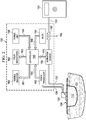
FIGURE 1 is a schematic diagram, with a portion shown in cross section, of an illustrative, non-limiting embodiment of a system for managing reduced pressure at multiple tissue sites undergoing reduced pressure treatment on a patient; -
FIGURE 2 is a schematic diagram of a portion of an illustrative embodiment of a system for managing reduced pressure at multiple tissue sites undergoing reduced pressure treatment on a patient showing an illustrative, non-limiting configuration of a pressure management device; -
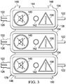
FIGURE 3 is a schematic, elevation view of an illustrative embodiment of an integral module formed from a plurality of pressure management devices; -
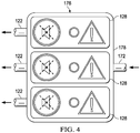
FIGURE 4 is a schematic, elevation view of an illustrative embodiment of an integral module that involves a conduit delivering reduced pressure that is split to provide reduced pressure to a plurality of reduced-pressure delivery conduits; and -
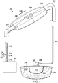
FIGURE 5 is a schematic, perspective view, with a portion shown as a diagram and a portion as a cross section, of another illustrative embodiment of a portion of a system for managing reduced pressure at multiple tissue sites undergoing reduced pressure treatment on a patient. - In the following detailed description of the illustrative, non-limiting embodiments, reference is made to the accompanying drawings that form a part hereof. These embodiments are described in sufficient detail to enable those skilled in the art to practice the invention, and it is understood that other embodiments may be utilized and that logical structural, mechanical, electrical, and chemical changes may be made without departing from the spirit or scope of the invention. To avoid detail not necessary to enable those skilled in the art to practice the embodiments described herein, the description may omit certain information known to those skilled in the art. The following detailed description is, therefore, not to be taken in a limiting sense, and the scope of the illustrative embodiments are defined only by the appended claims.
- Reduced pressure provided to tissue sites encourages healing at those tissue sites. To accommodate multiple tissue sites, e.g., multiple wounds on a patient, multiple conduits may be used to deliver reduced pressure. A single reduced pressure source may be used with the multiple conduits branched off one conduit. Pressure monitoring is currently located in existing reduced-pressure sources and only one conduit communicates pressure to the reduced-pressure source. If only one conduit, which is associated with one tissue site, is monitored, as is the case when monitoring is done at the reduced-pressure source alone, pressure at other tissue sites may be unmonitored. This means that the pressure at the different tissue sites may vary greatly and yet go unnoticed. This, in turn, may cause a detrimental result in some situations. For example, if a graft does not receive reduced pressure for two hours, the graft may not take. With the current system, each tissue site of the plurality of tissue sites is monitored, and issues with reduced pressure delivery may be identified and addressed. An illustrative embodiment of a
system 100 is presented that includes, among other things, pressure monitoring at multiple tissue sites. - Referring now to the drawings and initially to
FIGURE 1 , thesystem 100 for managing reduced pressure at a plurality oftissue sites 102 that are undergoing reduced pressure treatment on apatient 104 is presented. A plurality of reduced-pressure dressings 106 are used with the plurality oftissue sites 102. Typically, one of the plurality of reduced-pressure dressings 106 is associated with one of the plurality oftissue sites 102. Thetissue sites 102 may comprise a single extended tissue site or wound or may be discrete wound sites or tissue sites. Each of thetissue sites 102 may be the bodily tissue of any human, animal, or other organism, including bone tissue, adipose tissue, muscle tissue, dermal tissue, vascular tissue, connective tissue, cartilage, tendons, ligaments, or any other tissue. Unless otherwise indicated, as used throughout this document, "or" does not require mutual exclusivity. Treatment of thetissue sites 102 may include removal of fluids, e.g., exudate or ascites. - The plurality of reduced-
pressure dressings 106 in the illustrative embodiment ofFIGURE 1 is shown with a first reduced-pressure dressing 108 and a second reduced-pressure dressing 110. The plurality of reduced-pressure dressings 106 may include any structure suitable for providing reduced pressure to a tissue site and removing fluids. For example, in one illustrative embodiment, the first reduced-pressure dressing 108 includes a manifold 112 that is disposed proximate to one of thetissue sites 102 with which themanifold 112 is associated. The manifold 112 is covered with a sealingmember 114, which may include anattachment device 116, that creates a fluid seal. A fluid seal is a seal adequate to maintain reduced pressure at a desired tissue site given the particular reduced-pressure source or subsystem involved. The sealingmember 114, which may include theattachment device 116, creates a sealedspace 118 in which the manifold 112 may reside. A reduced-pressure interface 120 may be placed through an aperture (not shown) and the sealingmember 114 to provide reduced pressure into the sealedspace 118 and in particular to themanifold 112. For example, the reducedpressure interface 120 may be a T.R.A.C.® Pad or Sensa T.R.A.C.® Pad available from KCI of San Antonio, Texas. The reduced-pressure interface 120 delivers the reduced pressure to the sealedspace 118. The second reduced-pressure dressing 110 is analogous to the first reduced-pressure dressing 108. - With respect to the manifold 112, a manifold is generally a substance or structure that is provided to assist in applying reduced pressure to, delivering fluids to, or removing fluids from a tissue site, e.g.,
tissue site 102. The manifold 112 typically includes a plurality of flow channels or pathways that distribute fluids provided to and removed from thetissue site 102 around themanifold 112. In one illustrative embodiment, the flow channels or pathways are interconnected to improve distribution of fluids provided or removed from thetissue site 102. The manifold 112 comprises one or more of the following: a biocompatible material that is capable of being placed in contact with thetissue site 102 and distributing reduced pressure to thetissue site 102; devices that have structural elements arranged to form flow channels, such as, for example, cellular foam, open-cell foam, porous tissue collections, liquids, gels, and foams that include, or cure to include, flow channels; material that may be porous and may be made from foam, gauze, felted mat, or any other material suited to a particular biological application; foam with interconnected cells; polyurethane; open-cell, reticulated foam such as GranuFoam® material manufactured by Kinetic Concepts, Incorporated of San Antonio, Texas; bioresorbable material; or scaffold material. In some situations, the manifold 112 may also be used to distribute fluids such as medications, antibacterials, growth factors, and various solutions to thetissue site 102. Other layers may be included in or on the manifold 112, such as absorptive materials, wicking materials, hydrophobic materials, and hydrophilic materials. - In one illustrative embodiment, the manifold 112 may be constructed from bioresorbable materials that do not have to be removed from a patient's body following use of the reduced-pressure dressing 108, 110. Suitable bioresorbable materials may include, without limitation, a polymeric blend of polylactic acid (PLA) and polyglycolic acid (PGA). The polymeric blend may also include without limitation polycarbonates, polyfumarates, and capralactones. The manifold 112 may further serve as a scaffold for new cell-growth, or a scaffold material may be used in conjunction with the manifold 112 to promote cell-growth. A scaffold is a substance or structure used to enhance or promote the growth of cells or formation of tissue, such as a three-dimensional porous structure that provides a template for cell growth. Illustrative examples of scaffold materials include calcium phosphate, collagen, PLA/PGA, coral hydroxy apatites, carbonates, or processed allograft materials.
- The sealing
member 114 may be any material that provides a fluid seal. The sealingmember 114 may, for example, be an impermeable or semi-permeable, elastomeric material. Examples of elastomers may include, but are not limited to, natural rubbers, polyisoprene, styrene butadiene rubber, chloroprene rubber, polybutadiene, nitrile rubber, butyl rubber, ethylene propylene rubber, ethylene propylene diene monomer, chlorosulfonated polyethylene, polysulfide rubber, polyurethane (PU), EVA film, co-polyester, and silicones. Additional, specific examples of sealing member materials include a silicone drape, 3M Tegaderm® drape, polyurethane (PU) drape such as one available from Avery Dennison Corporation of Pasadena, California. - The
attachment device 116 may be used to hold the sealingmember 114 against the patient'sepidermis 111 or another layer, such as a gasket or additional sealing member, or another location. Theattachment device 116 may take numerous forms. For example, theattachment device 116 may be a medically acceptable, pressure-sensitive adhesive that extends about a periphery of the sealingmember 114. - The reduced-
pressure dressings 106 provide reduced pressure to thetissue sites 102. Reduced pressure is generally a pressure less than the ambient pressure at a tissue site that is being subjected to treatment. In most cases, this reduced pressure will be less than the atmospheric pressure at which the patient is located. Alternatively, the reduced pressure may be less than a hydrostatic pressure at the tissue site. Unless otherwise indicated, values of pressure stated herein are gauge pressures. The reduced pressure delivered may be constant or varied (patterned or random) and may be delivered continuously or intermittently. Although the terms "vacuum" and "negative pressure" may be used to describe the pressure applied to the tissue site, the actual pressure applied to the tissue site may be more than the pressure normally associated with a complete vacuum. Consistent with the use herein, an increase in reduced pressure or vacuum pressure typically refers to a relative reduction in absolute pressure. - A plurality of reduced-
pressure delivery conduits 122 may be fluidly coupled to a reduced-pressure source 124. The reduced-pressure delivery conduits 122 may be conduits for carrying reduced pressure and removing liquids alone or may be combined with one or more lumens for sensing pressure and providing a vent or a purge. For description purposes, a distinct plurality ofsensing conduits 126, or lumens, is shown associated with the plurality of reduced-pressure delivery conduits 122, but it should be understood that thesensing conduits 126 may be incorporated into the plurality of reduced-pressure delivery conduits 122 as a lumen in a multi-lumen conduit. - The reduced-
pressure source 124 provides reduced pressure. The reduced-pressure source 124 may be any device or source for supplying a reduced pressure, such as a vacuum pump, wall suction, micro-pump, or other source. If the reduced-pressure source 124 is a micro-pump, the micro-pump may be directly coupled to the plurality ofmanagement devices 128. While the amount and nature of reduced pressure applied to a tissue site will typically vary according to the application, the reduced pressure will typically be between -5 mm Hg (-667 Pa) and -500 mm Hg (-66.7 kPa) and more typically between -75 mm Hg (-9.9 kPa) and -300 mm Hg (-39.9 kPa). For example, and not by way of limitation, the pressure may be -12, -12.5, -13, -14, -14.5, -15, -15.5, -16, -16.5, -17, -17.5, -18, -18.5, -19, -19.5, -20, -20.5, -21, -21.5, -22, -22.5, -23, -23.5, -24, -24.5, -25, -25.5, -26, -26.5 kPa or another pressure. - The plurality of
pressure management devices 128 may be coupled to the plurality of reduced-pressure delivery conduits 122 and fluidly coupled to the plurality ofsensing conduits 126. The plurality ofpressure management devices 128 may include, for example, a firstpressure management device 130 and a secondpressure management device 132. Each of the plurality ofpressure management devices 128 may include ahousing 134. Thehousing 134 may include avisual indicator 136 that may include indicators such as pressure disruption orcaution symbol 138 and a touchmute button 140. Amanual power switch 142 may also be included on thehousing 134 or on thevisual indicator 136. Eachhousing 134 may include afirst portion 144 and asecond portion 146 or edge. Afirst coupling member 148, which may include two components, may be coupled to thefirst portion 144. Asecond coupling member 150 may be formed on thesecond portion 146. Thefirst coupling member 148 and thesecond coupling member 150 are sized and configured to couple with one another either fixedley or releasably. As described further below in connection withFIGURE 3 , theoptional coupling members pressure management devices 128 to be combined to form an integral module, i.e., a single unit. Other techniques and devices, e.g., fasteners or clips, may be used to couple thepressure management devices 128. - Referring now primarily to
FIGURE 2 , thesystem 100 for managing reduced pressure at the plurality oftissue sites 102 is presented in diagram form with only the firstpressure management device 130 of the plurality ofpressure management devices 128 shown. It should be understood that any number of additionalpressure management devices 128 may be combined as part of thesystem 100. Additional aspects of the firstpressure management device 130 may be explained in more detail with reference toFIGURE 2 . - The first
pressure management device 130 is fluidly coupled to one of the plurality ofsensing conduits 126, and thesensing conduit 126 is fluidly coupled to a force transducer 152 (or pressure gauge) within the firstpressure management device 130. Theforce transducer 152 is able to develop a signal, e.g., an electrical signal, that indicates the pressure within thesensing conduit 126 or is otherwise able to detect various thresholds of pressure. Theforce transducer 152 is coupled at 154 to acontroller 156. Thecontroller 156 may be a printed wire assembly (PWA) or an application specific integrated circuit (ASIC), a microprocessor with associated memory, or other controller device. - The
controller 156 is able to thus monitor the pressure within thesensing conduit 126 and thereby to monitor pressure proximate to thetissue site 102. Thecontroller 156 receives power from apower unit 158, such as a battery or other source of electrical power. Thepower unit 158 is coupled at 159 to thecontroller 156. When thecontroller 156 determines that the reduced pressure within thesensing conduit 126 is inadequate (e.g., below a reduced-pressure threshold), such as may be caused by a leak in the reduced-pressure dressing associated with theparticular sensing conduit 126 or a blockage or other problem, thecontroller 156 may activate or modify an indicator, such as an audible indicator 160 (or alarm) or avisual indicator 162. Theaudible indicator 160 is shown coupled at 161 to thecontroller 156. Thevisual indicator 162 is shown coupled at 163 to thecontroller 156. A mute switch orbutton 164 may be associated with thecontroller 156 and is shown coupled at 166. Themute switch 164 may allow a user to silence theaudible indicator 160. Other user interfaces may be coupled to thecontroller 156 to control other aspects of the firstpressure management device 130. - A portion of the reduced-
pressure delivery conduit 122 may extend through the firstpressure management device 130, and an activation sensor ortransducer 168 may be fluidly coupled to the reduced-pressure delivery conduit 122. Theactivation sensor 168 can detect the presence of reduced pressure and provide asignal 170 to thecontroller 156. Thecontroller 156 may compare the pressure delivered through the reduced-pressure delivery conduit 122 with the sensing pressure in thesensing conduit 126 to make certain determinations concerning performance and may also use the signal from theactivation sensor 168 to continue to runcontroller 156 and other aspects of the firstpressure management device 130. - Referring now primarily to
FIGURES 1 and2 , in operation, according to one illustrative embodiment, a user may apply the plurality of reduced-pressure dressings 106 to the plurality oftissue sites 102. For example, themanifold 112 of the first reduced-pressure dressing 108 may be placed against thetissue site 102 and then be covered by the sealingmember 114 to create the sealedspace 118. A reducedpressure interface 120, if not already installed, may be installed to provide reduced pressure to the sealedspace 118 or otherwise to themanifold 112. Other reduced-pressure dressings may be applied to eachtissue site 102 for which treatment is desired. - The plurality of reduced-
pressure delivery conduits 122 may be fluidly coupled to the reduced-pressure source 124 in a one-to-one fashion. In this regard, the reduced-pressure source 124 may have a first conduit 172 (FIGURE 1 ) that goes to a branching member orsplitter 174 that fluidly couples the plurality of reduced-pressure delivery conduits 122 to the reduced-pressure source 124. The plurality ofsensing conduits 126 are fluidly coupled to the plurality ofpressure management devices 128. - The reduced-
pressure source 124 is activated and begins to deliver reduced pressure to the plurality of reduced-pressure dressings 106. The plurality ofpressure management devices 128 may be activated either automatically by theactivation sensors 168 or manually by the user using an interface such aspower switch 142. Thus, reduced pressure is delivered to thetissue sites 102 and is monitored for eachtissue site 102. If there is a problem with the reduced pressure delivery at atissue site 102 as sensed by one of the plurality ofsensing conduits 126, thepressure management device 128 associated with that particular sensing conduit of the plurality ofsensing conduits 126 will sense the inadequate pressure via the associatedforce transducer 152. Thecontroller 156, which monitors theforce transducer 152, will then provide an indication using theaudible indicator 160 or thevisual indicator 162. The user may then identify which reduced-pressure dressing of the plurality of reduced-pressure dressings 106 is having the difficulty. Corrective action may then be readily taken. - As shown in
FIGURE 3 , the plurality ofpressure management devices 128 may be coupled using thefirst coupling members 148 and thesecond coupling members 150 to form anintegral module 176. Theintegral module 176 provides for more convenient movement by the user and may also be more aesthetic. - Referring now primarily to
FIGURE 4 , an illustrative embodiment of anintegral module 176 orpressure management module 176 is presented that is analogous in most respects to theintegrated module 176 shown inFIGURE 3 . Accordingly, some parts are labeled but not further described here. There are, however, two main differences. First, theintegrated module 176 ofFIGURE 4 may be manufactured with three otherwise independent pressure management devices is asingle housing 178. Second, and related, the integratedpressure management module 176 functions as a junction or branching member or splitter to receive reduced pressure from afirst conduit 172 from a reduced-pressure source and to provide reduced pressure to each of the plurality ofpressure management devices 128 for delivery through a plurality of reduced-pressure delivery conduits 122. While not explicitly shown, associated with or formed as part of the reduced-pressure delivery conduits 122 is a plurality of pressure sensing lumens or conduits. The plurality of sensing lumens allows the plurality of pressure management devices to monitor pressure at a plurality of tissue sites. At least one reduced-pressure delivery conduit 122 may be a sensing lumen that provides pressure for sensing purposes to the reduced-pressure source, e.g., reduced-pressure source 124 inFIGURE 1 . - Referring again primarily to
FIGURE 2 , another illustrative embodiment ofsystem 100 will be presented. With respect to this embodiment ofsystem 100, the reduced pressure delivered by reduced-pressure source 124 may be at a reduced pressure greater (more negative on an absolute pressure scale) than required anywhere in thesystem 100 and then stepped down to the desired pressure at various locations. Thus, as an aspect of each of the plurality ofpressure management devices 128, apressure regulating valve 182 may be provided to adjust the reduced pressure delivered from the reduced-pressure source 124 to the specific pressure desired for aparticular tissue site 102 associated with that particular pressure management device. - The
pressure regulating valve 182 may have anadjustment control 184 for setting the desired pressure. Thus, as one example, a single reduced-pressure source 124 may be used that provides relatively higher reduced pressure (for example, but not by way of limitation, -200 mm Hg) and then adjusted by thepressure regulating valve 182 to a first desired pressure (e.g., but not by way of limitation, to -150 mm Hg) and delivered to a tissue site from which a graft has been taken. Thesystem 100 also provides reduced pressure to a reduced-pressure dressing at the tissue site where the graft has been placed and may do so at a second desired pressure that is relatively less than the first desired pressure (e.g., but not by way of limitation, -50 mm Hg). In another illustrative embodiment, thecontroller 156 may control theadjustment control 184. The desired pressure may be set by a user using a user interface to thecontroller 156. - Referring now primarily to
FIGURE 5 , an illustrative,non-limiting system 200 for managing reduced pressure at a plurality of tissue sites, e.g.,tissue site 202, undergoing reduced pressure treatment on apatient 204 is presented. Thesystem 200 is analogous in many respects to thesystem 100 ofFIGURE 1 . While only one reduced-pressure dressing 208 and onepressure management device 228 is shown, it should be understand that thesystem 200 contemplates a plurality of each. The plurality of reduced-pressure dressings, such as reduced-pressure dressing 208, is placed on the tissue sites, e.g.,tissue site 202. With each reduced-pressure dressing, a reduced-pressure interface 220 may be used to provide reduced pressure to a sealedspace 218 that contains amanifold 212 and also allows for sensing of the pressure in the sealedspace 218. - A reduced-
pressure source 224 delivers reduced pressure to a first plurality of reduced-pressure delivery conduits 223. Afirst conduit 272 may be used to deliver the reduced pressure to one ormore splitters 274 or distributors that are fluidly coupled to the first plurality of reduced-pressure delivery conduits 223. Each of the first reduced-pressure delivery conduits 223 has afirst end 225 and asecond end 227. Coupled to thesecond end 227 of each of the first reduced-pressure delivery conduits 223 is a firstpressure management connector 286. A secondpressure management connector 288 is releasably coupled to the firstpressure management connector 286 to form apressure management device 228. A second plurality of reduced-pressure delivery conduits 290 may be used to fluidly couple the reduced-pressure interface 220 to the associated secondpressure management connector 288 for each reduced-pressure dressing. Each of the second plurality of reduced-pressure delivery conduits 290 has afirst end 292 and asecond end 294. The secondpressure management connector 288 is coupled to thefirst end 292 of the associated conduit of the second plurality of reduced-pressure conduits 290. - Each
pressure management device 228 created by coupling the firstpressure management connector 286 and the secondpressure management connector 288 provides both a fluid coupling and may also function analogously to thepressure management devices 128 ofFIGURES 1-3 with respect to monitoring and control. Thepressure management devices 228 provide a quick connection and also readily allow for one portion, e.g., the firstpressure management connector 286, to be reused and for another portion, e.g., the secondpressure management connector 288, to be discarded after use. Physically coupling theconnectors connectors FIGURE 2 again, various components of the firstpressure management device 130 may be associated with either of theconnectors pressure management device 228. - In one illustrative embodiment, the
audible indicator 160 andvisual indicator 162 may be associated with the firstpressure management connector 286. Thecontroller 156,power unit 158,mute switch 164, andforce transducer 152 may be associated with the secondpressure management connector 288. Various combinations and permutations of the components may be associated with the twoconnectors pressure regulating valve 182 may also be associated with the secondpressure management connector 288. - As used herein, the term "coupled" includes coupling via a separate object and includes direct coupling. The term "coupled" also encompasses two or more components that are continuous with one another by virtue of each of the components being formed from the same piece of material. Also, the term "coupled" may include chemical, such as via a chemical bond, mechanical, thermal, or electrical coupling. Fluid coupling means that fluid may be in communication between the designated parts or locations.
- In another illustrative embodiment, the pressure management device may have no electronics and may use a physical device to monitor pressure and to indicate inadequate pressure. For example, a pop-up pressure valve may be associated with each sensing lumen that is compressed under adequate reduced pressure, but expands and is visible when inadequate reduced pressure exists.
- The
pressure management devices 128 may be used with any reduced-pressure source, which may be any device for supplying a reduced pressure, such as a vacuum pump, wall suction, or other source. With the inclusion of apressure regulating valve 182, thepressure management devices 128 allow for a single reduced-pressure source to supply and monitor reduced pressure at different pressures at different tissue sites. - The reduced-pressure source may be a monitored system that monitors one tissue site from which one conduit is fluidly coupled, and the pressure management devices may be added to the additional conduits associated with additional tissue sites.
- Referring again generally to
FIGURES 1 and4 , in another illustrative embodiment, asystem 100 for managing reduced pressure at a plurality oftissue sites 102 that are undergoing reduced pressure treatment on apatient 104 is presented. In this illustrative embodiment, anintegral module 176 has a plurality ofpressure management devices 128 similar to those presented inFIGURE 4 , but with only one controller (not explicitly shown) for theintegral module 176. The force transducers associated with eachpressure management device 128 are coupled to the one controller for theintegral module 176. - Although the present invention and its advantages have been disclosed in the context of certain illustrative, non-limiting embodiments, it should be understood that various changes, substitutions, permutations, and alterations can be made without departing from the scope of the invention as defined by the appended claims. It will be appreciated that any feature that is described in connection to any one embodiment may also be applicable to any other embodiment.
- It will be understood that the benefits and advantages described above may relate to one embodiment or may relate to several embodiments. It will further be understood that reference to "an" item refers to one or more of those items.
- The steps of the methods described herein may be carried out in any suitable order, or simultaneously where appropriate.
- Where appropriate, aspects of any of the embodiments described above may be combined with aspects of any of the other embodiments described to form further examples having comparable or different properties and addressing the same or different problems.
- It will be understood that the above description of preferred embodiments is given by way of example only and that various modifications may be made by those skilled in the art. The above specification, examples and data provide a complete description of the structure and use of exemplary embodiments of the invention. Although various embodiments of the invention have been described above with a certain degree of particularity, or with reference to one or more individual embodiments, those skilled in the art could make numerous alterations to the disclosed embodiments without departing from the scope of the claims.
- Aspects of the invention are disclosed in the following numbered clauses:
- Clause 1. A system for managing reduced pressure at a plurality of tissue sites undergoing reduced pressure treatment on a patient, the system comprising:
- a reduced-pressure source for providing reduced pressure;
- a plurality of reduced-pressure delivery conduits fluidly coupled to the reduced- pressure source;
- a plurality of reduced-pressure dressings fluidly coupled to the plurality of reduced- pressure delivery conduits in a one-to-one fashion;
- a plurality of pressure management devices;
- a plurality of sensing conduits fluidly coupled to the plurality of pressure management devices in a one-to-one fashion;
- wherein each reduced-pressure dressing has a sensing conduit of the plurality of sensing conduits and a reduced-pressure delivery conduit of the plurality of reduced-pressure delivery conduits associated with the reduced-pressure dressing; and
- wherein each pressure management device of the plurality of pressure management devices comprises:
- a controller,
- a power unit electrically coupled to the controller for providing power to the controller,
- a force transducer associated with a sensing conduit of the plurality of
- sensing conduits and electrically coupled to the controller for determining if a reduced-pressure threshold exists at a tissue site associated with the sensing conduit, and
- an indicator coupled to the controller for indicating when insufficient
- pressure exists in an associated sensing conduit.
- Clause 2. The system of clause 1, wherein each pressure management device further comprises an activation sensor fluidly coupled to a reduced-pressure delivery conduit associated with the pressure management device and electrically coupled to the controller.
- Clause 3. The system of clause 1 or clause 2, wherein the indicator is selected from the group of an audible indicator and a visual indicator.
- Clause 4. The system of clause 1 or any preceding clause, wherein each pressure management device further comprises a muting switch.
- Clause 5. The system of clause 1 or any preceding clause, wherein the plurality of pressure management devices are coupled to form an integral module.
- Clause 6. The system of clause 1 or any preceding clause, wherein each of the plurality of reduced-pressure dressings comprises: a manifold for placing proximate to the tissue site, a sealing member for covering the manifold and tissue site to create a sealed space, and a reduced-pressure interface for providing reduced pressure to the sealed space.
- Clause 7. The system of clause 1 or any preceding clause, wherein each of the plurality of pressure management devices comprises:
- a housing,
- a first coupling member coupled to a first portion of the housing,
- a second coupling member coupled to a second portion of the housing, and wherein the first coupling member is sized and configured to couple with the second coupling member on another of the plurality of pressure management devices, whereby adjacent pressure management devices may be coupled.
- Clause 8. A method for managing reduced pressure at a plurality of tissue sites undergoing reduced pressure treatment on a patient, the method comprising:
- providing a reduced-pressure source;
- fluidly coupling a plurality of reduced-pressure delivery conduits to the reduced- pressure source; disposing a plurality of reduced-pressure dressings proximate to the plurality of tissue sites;
- fluidly coupling the plurality of reduced-pressure dressings to the plurality of reduced-pressure delivery conduits;
- providing a plurality of pressure management devices for monitoring pressure; fluidly coupling a plurality of a sensing conduits to the plurality of pressure management devices in a one-to-one fashion; and
- wherein each reduced-pressure dressing has a sensing conduit of the plurality of sensing conduits and a reduced-pressure delivery conduit of the plurality of reduced-pressure delivery conduits associated with the reduced-pressure dressing.
- Clause 9. The method of clause 8, wherein each pressure management device of the plurality of pressure management devices comprises:
- a controller,
- a power unit electrically coupled to the controller for providing power to the controller,
- a force transducer associated with a sensing conduit of the plurality of sensing conduits and electrically coupled to the controller for determining if a reduced-pressure threshold exists at a tissue site associated with the sensing conduit, and
- an indicator coupled to the controller for indicating when insufficient
- pressure exists in an associated sensing conduit.
- Clause 10. The method of clause 9, wherein each pressure management device further comprises an activation sensor fluidly coupled to a reduced-pressure delivery conduit associated with the pressure management device and electrically coupled to the controller.
- Clause 11. The method of clause 9, wherein the indicator is selected from the group of an audible indicator and a visual indicator.
- Clause 12. The method of clause 9, clause 10, or clause 1 1, wherein each pressure management device further comprises a muting switch.
- Clause 13. The method of clause 8 or any of clauses 9-12, further comprising coupling the plurality of pressure management devices together to form an integral module.
- Clause 14. The method of clause 8 or any of clauses 9-13, wherein each of the plurality of reduced-pressure dressings comprises: a manifold for placing proximate to the tissue site, a sealing member for covering the manifold and tissue site to create a sealed space, and a reduced-pressure interface for providing reduced pressure to the sealed space.
- Clause 15. A method of manufacturing a system for managing reduced pressure at plurality of tissue sites undergoing reduced pressure treatment on a patient, the method comprising:
- providing a reduced-pressure source for providing reduced pressure;
- providing a plurality of reduced-pressure delivery conduits;
- fluidly coupling the plurality of reduced-pressure delivery conduits to the reduced- pressure source;
- providing a plurality of reduced-pressure dressings;
- providing plurality of pressure management devices;
- providing a plurality of sensing conduits;
- fluidly coupling the plurality of pressure management devices in a one-to-one fashion to the plurality of sensing conduits;
- wherein each reduced-pressure dressing has a sensing conduit of the plurality of sensing conduits and a reduced-pressure delivery conduit of the plurality of reduced-pressure delivery conduits associated with the reduced-pressure dressing; and
- wherein each pressure management device of the plurality of pressure management devices comprises:
- a controller,
- a power unit electrically coupled to the controller for providing power to the controller,
- a force transducer associated with a sensing conduit of the plurality of sensing conduits and electrically coupled to the controller for determining if a reduced-pressure threshold exists at a tissue site associated with the sensing conduit, and
- an indicator coupled to the controller for indicating when insufficient
- pressure exists in the associated sensing conduit.
- Clause 16. A system for managing reduced pressure at a plurality of tissue sites undergoing reduced pressure treatment on a patient, the system comprising:
- a reduced-pressure source for providing reduced pressure;
- a pressure management module;
- a first conduit fluidly coupled between the reduced-pressure source and the pressure management module for supplying reduced pressure to the pressure management module;
- a plurality of reduced-pressure dressings;
- a plurality of reduced-pressure delivery conduits fluidly coupled to the pressure management module; wherein the plurality of reduced-pressure dressings are coupled to the plurality of reduced-pressure delivery conduits;
- a plurality of a sensing conduits fluidly coupled to the pressure management module; and
- wherein each reduced-pressure dressing has a sensing conduit of the plurality of sensing conduits and a reduced-pressure delivery conduit of the plurality of reduced-pressure delivery conduits associated with the reduced-pressure dressing.
- Clause 17. The system of clause 16, wherein the pressure management module comprises a plurality of pressure management devices, and wherein each pressure management device of the plurality of pressure management devices comprises:
- a controller,
- a power unit electrically coupled to the controller for providing power to the controller,
- a force transducer associated with a sensing conduit of the plurality of
- sensing conduits and electrically coupled to the controller for determining if a reduced-pressure threshold exists at a tissue site associated with the sensing conduit, and
- an indicator coupled to the controller for indicating when insufficient
- pressure exists in an associated sensing conduit.
- Clause 18. The system of clause 16 or clause 17, wherein each pressure management device further comprises an activation sensor fluidly coupled to the first conduit and electrically coupled to the controller.
- Clause 19. The system of clause 16 or any of clauses 17-18, wherein the indicator is selected from the group of an audible indicator and a visual indicator.
- Clause 20. A system for managing reduced pressure at a plurality of tissue sites undergoing reduced pressure treatment on a patient, the system comprising:
- a reduced-pressure source for providing reduced pressure;
- a first plurality of reduced-pressure delivery conduits fluidly coupled to the reduced-pressure source, each reduced-pressure delivery conduit of the first plurality of reduced-pressure delivery conduits having a first end and a second end, and wherein the second end has a first pressure-management connector;
- a second plurality of reduced-pressure delivery conduits each having a first end and a second end, and wherein the first end has a second pressure-management connector;
- a plurality of reduced-pressure dressings coupled to the second plurality of reduced- pressure delivery conduits in a one-to-one fashion;
- wherein the first pressure management connectors of the plurality of reduced- pressure conduits are coupled to the second pressure -management connectors of the second plurality of reduced-pressure in a one-to-one fashion, and wherein the first pressure management connectors and second management connectors couple to form a plurality of pressure management devices;
- wherein each reduced-pressure dressing has one of the second reduced-pressure delivery conduits associated with the reduced-pressure dressing; and wherein each pressure management device of the plurality of pressure management devices comprises:
- a controller,
- a power unit electrically coupled to the controller for providing power to the controller, a force transducer associated with a sensing conduit of the first plurality of reduced-pressure conduits and electrically coupled to the controller for determining if a reduced-pressure threshold exists at a tissue site associated with the sensing conduit, and
- an indicator coupled to the controller for indicating when insufficient
- pressure exists at the associated sensing conduit.
- Clause 21. The system of clause 20, wherein for each pressure management device, the indicator is coupled to the first pressure management connector.
- Clause 22. The system of clause 20, wherein for each pressure management device, the indicator is coupled to the first pressure management connector and the controller, the power unit, and the force transducer are coupled to the second pressure management connector.
- Clause 23. A system for managing reduced pressure at a plurality of tissue sites undergoing reduced pressure treatment on a patient, the system comprising:
- a plurality of pressure management devices;
- a plurality of sensing conduits, each sensing conduit being fluidly coupled to a respective pressure management device and being for fluidly coupling to a tissue site;
- wherein each pressure management device of the plurality of pressure management devices comprises
- a pressure sensor for sensing the pressure within the sensing conduit associated with that pressure management device, and
- an indicator coupled to the controller for indicating when the sensed pressure is less than a threshold pressure.
- Clause 24. A system according to clause 23, wherein each pressure management device comprises a controller, and
a power unit electrically coupled to the controller for providing power to the controller, wherein the pressure sensor comprises a force transducer associated with the sensing conduit and electrically coupled to the controller. - Clause 25. A system according to clause 23 or 24, further comprising
a reduced-pressure source for providing reduced pressure; and
a plurality of reduced-pressure delivery conduits fluidly coupled to the reduced- pressure source, each delivery conduit being for delivering the reduced- pressure to a tissue site. - Clause 26. A system according to clause 23 or 24, further comprising
a first conduit for connection to a reduced pressure source, and
a plurality of reduced-pressure delivery conduits for delivering reduced pressure to a plurality of tissue sites, wherein the first conduit is fluidly connected to the plurality of delivery conduits by the plurality of pressure management devices. - Clause 27. The system of clause 25 or 26, wherein each pressure management device further comprises an activation sensor fluidly coupled to a reduced-pressure delivery conduit associated with the pressure management device.
- Clause 28. The system of any of clauses 23 to 27, wherein the indicator is selected from the group of an audible indicator and a visual indicator.
- Clause 29. The system of any of clauses 23 to 28, wherein each pressure management device further comprises a muting switch.
- Clause 30. The system of any of clauses 25 to 29, wherein the plurality of pressure management devices are coupled to form an integral module.
- Clause 31. The system of any of clauses 23 to 30, further comprising a plurality of reduced- pressure dressings for maintaining a reduced-pressure at a tissue site, each dressing being for coupling to a reduced-pressure delivery conduit.
- Clause 32. The system of any of clauses 23 to 31 , wherein each of the plurality of pressure management devices comprises:
- a housing,
- a first coupling member coupled to a first portion of the housing,
- a second coupling member coupled to a second portion of the housing, and wherein the first coupling member is sized and configured to couple with the second coupling member on another of the plurality of pressure management devices, whereby adjacent pressure management devices may be coupled.
- Clause 33. A system according to clause 23 wherein, each pressure management device comprises a first connector coupled to a first reduced pressure delivery conduit for delivery of reduced pressure to a tissue site, and a second connector coupled to a second reduced pressure delivery conduit for receiving reduced pressure from a source of reduced pressure, wherein the first and second connectors are connected to form the pressure management device.
- Clause 34. The system of clause 33, wherein for each pressure management device, the indicator is coupled to the first connector.
- Clause 35. The system of clause 33 or 34, wherein for each pressure management device, the indicator is coupled to the first connector and the sensor is coupled to the second connector.
Claims (11)
- A system for managing reduced pressure at a plurality of tissue sites undergoing reduced pressure treatment on a patient, the system comprising:a reduced-pressure source for providing reduced pressure;a pressure management module;a first conduit fluidly coupled between the reduced-pressure source and the pressure management module for supplying reduced pressure to the pressure management module;a plurality of reduced-pressure dressings;a plurality of reduced-pressure delivery conduits fluidly coupled to the pressure management module;wherein the plurality of reduced-pressure dressings are coupled to the plurality of reduced-pressure delivery conduits;a plurality of a sensing conduits fluidly coupled to the pressure management module; andwherein each reduced-pressure dressing has a sensing conduit of the plurality of sensing conduits and a reduced-pressure delivery conduit of the plurality of reduced-pressure delivery conduits associated with the reduced-pressure dressing.
- The system of claim 1, wherein the pressure management module comprises a plurality of pressure management devices, and wherein each pressure management device of the plurality of pressure management devices comprises:a controller;a power unit electrically coupled to the controller for providing power to the controller;a force transducer associated with a sensing conduit of the plurality of sensing conduits and electrically coupled to the controller for determining if a reduced-pressure threshold exists at a tissue site associated with the sensing conduit; andan indicator coupled to the controller for indicating when insufficient pressure exists in an associated sensing conduit.
- The system of any of claims 1-2, wherein each pressure management device further comprises an activation sensor fluidly coupled to the first conduit and electrically coupled to the controller.
- The system of any of claims 1-3, wherein the indicator is selected from the group of an audible indicator and a visual indicator.
- A method for managing reduced pressure at a plurality of tissue sites undergoing reduced pressure treatment on a patient, the method comprising:providing a reduced-pressure source;fluidly coupling a plurality of reduced-pressure delivery conduits to the reduced-pressure source;disposing a plurality of reduced-pressure dressings proximate to the plurality of tissue sites;fluidly coupling the plurality of reduced-pressure dressings to the plurality of reduced-pressure delivery conduits;providing a plurality of pressure management devices for monitoring pressure;fluidly coupling a plurality of sensing conduits to the plurality of pressure management devices in a one-to-one fashion; andwherein each reduced-pressure dressing has a sensing conduit of the plurality of sensing conduits and a reduced-pressure delivery conduit of the plurality of reduced-pressure delivery conduits associated with the reduced-pressure dressing.
- The method of claim 5, wherein each pressure management device of the plurality of pressure management devices comprises:a controller;a power unit electrically coupled to the controller for providing power to the controller;a force transducer associated with a sensing conduit of the plurality of sensing conduits and electrically coupled to the controller for determining if a reduced-pressure threshold exists at a tissue site associated with the sensing conduit; andan indicator coupled to the controller for indicating when insufficient pressure exists in an associated sensing conduit.
- The method of claim 6, wherein each pressure management device further comprises an activation sensor fluidly coupled to a reduced-pressure delivery conduit associated with the pressure management device and electrically coupled to the controller.
- The method of claim 6, wherein the indicator is selected from the group of an audible indicator and a visual indicator.
- The method of any of claims 6-8, wherein each pressure management device further comprises a muting switch.
- The method of any of claims 5-9, further comprising coupling the plurality of pressure management devices together to form an integral module.
- The method of any of claims 5-10, wherein each of the plurality of reduced-pressure dressings comprises:a manifold for placing proximate to the tissue site;a sealing member for covering the manifold and the tissue site to create a sealed space; anda reduced-pressure interface for providing reduced pressure to the sealed space.
Applications Claiming Priority (5)
| Application Number | Priority Date | Filing Date | Title |
|---|---|---|---|
| US41471810P | 2010-11-17 | 2010-11-17 | |
| PCT/US2011/060029 WO2012067916A1 (en) | 2010-11-17 | 2011-11-09 | Systems and methods for managing reduced pressure at a plurality of wound sites |
| EP17194474.7A EP3295971B1 (en) | 2010-11-17 | 2011-11-09 | Systems for managing reduced pressure at a plurality of wound sites |
| EP11784903.4A EP2640436B1 (en) | 2010-11-17 | 2011-11-09 | Systems for managing reduced pressure at a plurality of wound sites and method of manufacture |
| EP16159093.0A EP3053608B1 (en) | 2010-11-17 | 2011-11-09 | Systems for managing reduced pressure at a plurality of wound sites |
Related Parent Applications (3)
| Application Number | Title | Priority Date | Filing Date |
|---|---|---|---|
| EP16159093.0A Division EP3053608B1 (en) | 2010-11-17 | 2011-11-09 | Systems for managing reduced pressure at a plurality of wound sites |
| EP17194474.7A Division EP3295971B1 (en) | 2010-11-17 | 2011-11-09 | Systems for managing reduced pressure at a plurality of wound sites |
| EP11784903.4A Division EP2640436B1 (en) | 2010-11-17 | 2011-11-09 | Systems for managing reduced pressure at a plurality of wound sites and method of manufacture |
Publications (2)
| Publication Number | Publication Date |
|---|---|
| EP3574929A1 true EP3574929A1 (en) | 2019-12-04 |
| EP3574929B1 EP3574929B1 (en) | 2023-06-07 |
Family
ID=44993950
Family Applications (4)
| Application Number | Title | Priority Date | Filing Date |
|---|---|---|---|
| EP11784903.4A Active EP2640436B1 (en) | 2010-11-17 | 2011-11-09 | Systems for managing reduced pressure at a plurality of wound sites and method of manufacture |
| EP16159093.0A Active EP3053608B1 (en) | 2010-11-17 | 2011-11-09 | Systems for managing reduced pressure at a plurality of wound sites |
| EP17194474.7A Active EP3295971B1 (en) | 2010-11-17 | 2011-11-09 | Systems for managing reduced pressure at a plurality of wound sites |
| EP19186548.4A Active EP3574929B1 (en) | 2010-11-17 | 2011-11-09 | Systems for managing reduced pressure at a plurality of wound sites |
Family Applications Before (3)
| Application Number | Title | Priority Date | Filing Date |
|---|---|---|---|
| EP11784903.4A Active EP2640436B1 (en) | 2010-11-17 | 2011-11-09 | Systems for managing reduced pressure at a plurality of wound sites and method of manufacture |
| EP16159093.0A Active EP3053608B1 (en) | 2010-11-17 | 2011-11-09 | Systems for managing reduced pressure at a plurality of wound sites |
| EP17194474.7A Active EP3295971B1 (en) | 2010-11-17 | 2011-11-09 | Systems for managing reduced pressure at a plurality of wound sites |
Country Status (8)
| Country | Link |
|---|---|
| US (3) | US9364591B2 (en) |
| EP (4) | EP2640436B1 (en) |
| JP (2) | JP6114194B2 (en) |
| CN (1) | CN103189080B (en) |
| AU (1) | AU2011329273B2 (en) |
| CA (1) | CA2814873C (en) |
| TW (1) | TW201225932A (en) |
| WO (1) | WO2012067916A1 (en) |
Families Citing this family (82)
| Publication number | Priority date | Publication date | Assignee | Title |
|---|---|---|---|---|
| US9061095B2 (en) | 2010-04-27 | 2015-06-23 | Smith & Nephew Plc | Wound dressing and method of use |
| US8743023B2 (en) | 2010-07-23 | 2014-06-03 | Biological Illumination, Llc | System for generating non-homogenous biologically-adjusted light and associated methods |
| US9681522B2 (en) | 2012-05-06 | 2017-06-13 | Lighting Science Group Corporation | Adaptive light system and associated methods |
| JP2014500538A (en) | 2010-10-12 | 2014-01-09 | タニス,ケヴィン ジェイ. | Medical equipment |
| EP2640436B1 (en) | 2010-11-17 | 2016-03-30 | KCI Licensing, Inc. | Systems for managing reduced pressure at a plurality of wound sites and method of manufacture |
| GB201020005D0 (en) | 2010-11-25 | 2011-01-12 | Smith & Nephew | Composition 1-1 |
| CN107033596A (en) | 2010-11-25 | 2017-08-11 | 史密夫及内修公开有限公司 | Composition I-II and products thereof and purposes |
| RU2756986C2 (en) | 2011-02-04 | 2021-10-08 | Юниверсити Оф Массачусетс | Wound closure device with the creation of negative pressure |
| US9421132B2 (en) | 2011-02-04 | 2016-08-23 | University Of Massachusetts | Negative pressure wound closure device |
| US8754832B2 (en) | 2011-05-15 | 2014-06-17 | Lighting Science Group Corporation | Lighting system for accenting regions of a layer and associated methods |
| CA3101119C (en) * | 2011-06-24 | 2023-07-04 | Kci Licensing, Inc. | Reduced-pressure dressings employing tissue-fixation elements |
| EP2782615B1 (en) | 2011-11-23 | 2016-10-19 | KCI Licensing, Inc. | Reduced-pressure systems, methods, and devices for simultaneously treating a plurality of tissue sites |
| US20150159066A1 (en) | 2011-11-25 | 2015-06-11 | Smith & Nephew Plc | Composition, apparatus, kit and method and uses thereof |
| EP2825220B2 (en) | 2012-03-12 | 2021-03-03 | Smith & Nephew PLC | Reduced pressure apparatus and methods |
| CN104661601B (en) | 2012-05-22 | 2018-06-22 | 史密夫及内修公开有限公司 | Apparatus and method for wound therapy |
| WO2013175309A1 (en) | 2012-05-24 | 2013-11-28 | Smith & Nephew Plc | Devices and methods for treating and closing wounds with negative pressure |
| EP2872085A1 (en) | 2012-07-16 | 2015-05-20 | Smith&Nephew, Inc. | Negative pressure wound closure device |
| EP2895213B8 (en) * | 2012-09-12 | 2017-08-30 | KCI Licensing, Inc. | Systems for collecting exudates in reduced-pressure therapy |
| US9744278B2 (en) | 2012-10-25 | 2017-08-29 | Kci Licensing, Inc. | Wound connection pad with pneumatic connection confirmation ability |
| CA2902776C (en) | 2013-03-13 | 2023-03-07 | Smith & Nephew Inc. | Wound treatment apparatus and use thereof |
| US9737649B2 (en) | 2013-03-14 | 2017-08-22 | Smith & Nephew, Inc. | Systems and methods for applying reduced pressure therapy |
| AU2014236701B2 (en) | 2013-03-14 | 2018-07-19 | Smith & Nephew Inc. | Systems and methods for applying reduced pressure therapy |
| EP2968015B1 (en) | 2013-03-14 | 2018-05-16 | Smith & Nephew PLC | Compressible wound fillers and systems and methods of use in treating wounds with negative pressure |
| US10695226B2 (en) | 2013-03-15 | 2020-06-30 | Smith & Nephew Plc | Wound dressing and method of treatment |
| US10493184B2 (en) | 2013-03-15 | 2019-12-03 | Smith & Nephew Plc | Wound dressing and method of treatment |
| EP2968647B1 (en) | 2013-03-15 | 2022-06-29 | Smith & Nephew plc | Wound dressing sealant and use thereof |
| US20160120706A1 (en) | 2013-03-15 | 2016-05-05 | Smith & Nephew Plc | Wound dressing sealant and use thereof |
| CN105530898B (en) | 2013-07-16 | 2020-02-28 | 史密夫及内修公开有限公司 | Equipment for wound treatment |
| CA2920850C (en) | 2013-08-13 | 2022-08-30 | Smith & Nephew, Inc. | Systems and methods for applying reduced pressure therapy |
| EP3052156B1 (en) * | 2013-10-02 | 2020-12-23 | 3M Innovative Properties Company | Diposable reduced-pressure therapy system with electronic feedback |
| JP6723917B2 (en) | 2013-10-21 | 2020-07-15 | スミス アンド ネフュー インコーポレイテッド | Negative pressure wound closure device |
| CN103800993A (en) * | 2014-02-28 | 2014-05-21 | 昆山韦睿医疗科技有限公司 | Negative-pressure wound treatment equipment and system |
| US12133789B2 (en) * | 2014-07-31 | 2024-11-05 | Smith & Nephew, Inc. | Reduced pressure therapy apparatus construction and control |
| EP3659638B1 (en) | 2014-07-31 | 2026-01-07 | Smith & Nephew, Inc. | Systems and methods for applying reduced pressure therapy |
| EP3240586B1 (en) | 2014-12-30 | 2024-08-28 | Smith & Nephew, Inc | System for applying reduced pressure therapy |
| EP3701920B1 (en) | 2015-04-27 | 2024-06-05 | Smith & Nephew plc | Reduced pressure apparatus and methods |
| EP4209201A1 (en) | 2015-04-29 | 2023-07-12 | Smith & Nephew, Inc. | Negative pressure wound closure device |
| US10575991B2 (en) | 2015-12-15 | 2020-03-03 | University Of Massachusetts | Negative pressure wound closure devices and methods |
| US10814049B2 (en) | 2015-12-15 | 2020-10-27 | University Of Massachusetts | Negative pressure wound closure devices and methods |
| AU2017218439B2 (en) | 2016-02-12 | 2022-07-28 | Smith & Nephew, Inc. | Systems and methods for detecting operational conditions of reduced pressure therapy |
| JP1586116S (en) | 2016-02-29 | 2017-09-19 | ||
| EP3423123B1 (en) | 2016-03-04 | 2024-11-13 | Smith & Nephew plc | Negative pressure wound therapy apparatus for post breast surgery wounds |
| US11723809B2 (en) | 2016-03-07 | 2023-08-15 | Smith & Nephew Plc | Wound treatment apparatuses and methods with negative pressure source integrated into wound dressing |
| WO2017160412A1 (en) * | 2016-03-17 | 2017-09-21 | Kci Licensing, Inc. | Systems and methods for treating a tissue site using one manifold and multiple therapy units |
| JP7027332B2 (en) | 2016-04-26 | 2022-03-01 | スミス アンド ネフュー ピーエルシー | Wound dressing and usage with an integrated negative pressure source with fluid infiltration prevention components |
| CA3038206A1 (en) | 2016-05-03 | 2017-11-09 | Smith & Nephew Plc | Optimizing power transfer to negative pressure sources in negative pressure therapy systems |
| US11305047B2 (en) | 2016-05-03 | 2022-04-19 | Smith & Nephew Plc | Systems and methods for driving negative pressure sources in negative pressure therapy systems |
| WO2017191154A1 (en) | 2016-05-03 | 2017-11-09 | Smith & Nephew Plc | Negative pressure wound therapy device activation and control |
| EP4059530B1 (en) | 2016-05-13 | 2025-07-23 | Smith & Nephew, Inc. | Automatic wound coupling detection in negative pressure wound therapy systems |
| US11413388B2 (en) * | 2016-05-24 | 2022-08-16 | Somavac Medical Solutions, Inc. | Portable device with disposable reservoir for collection of internal fluid after surgery from a plurality of sites simultaneously |
| CA3034789A1 (en) | 2016-08-25 | 2018-03-01 | Smith & Nephew Plc | Absorbent negative pressure wound therapy dressing |
| US12447260B2 (en) | 2016-09-30 | 2025-10-21 | Smith & Nephew Plc | Negative pressure wound treatment apparatuses and methods with integrated electronics |
| WO2019053101A1 (en) | 2017-09-13 | 2019-03-21 | Smith & Nephew Plc | Negative pressure wound treatment apparatuses and methods with integrated electronics |
| JP7055795B2 (en) | 2016-09-30 | 2022-04-18 | スミス アンド ネフュー ピーエルシー | Negative pressure wound healing equipment and methods with integrated electronic devices |
| US11282602B2 (en) * | 2016-10-26 | 2022-03-22 | Carefusion 2200, Inc. | Device and method for mobile monitoring of drainage catheter |
| CN106581789B (en) * | 2016-12-12 | 2023-05-26 | 武汉维斯第医用科技股份有限公司 | External multi-pipeline converter for negative pressure closed drainage system |
| US12005181B2 (en) | 2016-12-12 | 2024-06-11 | Smith & Nephew Plc | Pressure wound therapy status indication via external device |
| AU2018228663B2 (en) * | 2017-02-28 | 2023-05-18 | T.J.Smith And Nephew, Limited | Multiple dressing negative pressure wound therapy system |
| WO2018162613A1 (en) | 2017-03-08 | 2018-09-13 | Smith & Nephew Plc | Negative pressure wound therapy device control in presence of fault condition |
| JP7162003B2 (en) | 2017-03-15 | 2022-10-27 | スミス アンド ネフュー ピーエルシー | Multiple Dressing Negative Pressure Wound Therapy System with Calibrated Leak Paths |
| WO2018195101A1 (en) | 2017-04-19 | 2018-10-25 | Smith & Nephew, Inc. | Negative pressure wound therapy canisters |
| WO2018206420A1 (en) | 2017-05-09 | 2018-11-15 | Smith & Nephew Plc | Redundant controls for negative pressure wound therapy systems |
| GB201718070D0 (en) | 2017-11-01 | 2017-12-13 | Smith & Nephew | Negative pressure wound treatment apparatuses and methods with integrated electronics |
| WO2019086332A1 (en) | 2017-11-01 | 2019-05-09 | Smith & Nephew Plc | Negative pressure wound treatment apparatuses and methods with integrated electronics |
| GB201718072D0 (en) | 2017-11-01 | 2017-12-13 | Smith & Nephew | Negative pressure wound treatment apparatuses and methods with integrated electronics |
| GB201718054D0 (en) | 2017-11-01 | 2017-12-13 | Smith & Nephew | Sterilization of integrated negative pressure wound treatment apparatuses and sterilization methods |
| WO2019190753A1 (en) * | 2018-03-29 | 2019-10-03 | Kci Licensing, Inc. | A system for managing instillation therapy on multiple wounds with a single fluid source |
| US12070545B2 (en) | 2018-07-16 | 2024-08-27 | Solventum Intellectual Properties Company | Wound therapy system with conduit blockage detection |
| CA3108457A1 (en) * | 2018-08-29 | 2020-03-05 | Aatru Medical, LLC | Negative pressure treatment including mechanical and chemical pump |
| GB201814158D0 (en) | 2018-08-31 | 2018-10-17 | Smith & Nephew | Blockage and leak detection in multiple dressing reduced pressure wound therapy systems |
| USD898925S1 (en) | 2018-09-13 | 2020-10-13 | Smith & Nephew Plc | Medical dressing |
| US11298268B2 (en) | 2018-09-19 | 2022-04-12 | Deroyal Industries, Inc. | Multiple-wound negative pressure wound therapy using multiple fluid collection volumes |
| WO2020124038A1 (en) | 2018-12-13 | 2020-06-18 | University Of Massachusetts | Negative pressure wound closure devices and methods |
| GB201903774D0 (en) | 2019-03-20 | 2019-05-01 | Smith & Nephew | Negative pressure wound treatment apparatuses and methods with integrated electronics |
| GB201907716D0 (en) | 2019-05-31 | 2019-07-17 | Smith & Nephew | Systems and methods for extending operational time of negative pressure wound treatment apparatuses |
| US11484640B2 (en) | 2019-07-03 | 2022-11-01 | T.J.Smith And Nephew, Limited | Negative pressure wound therapy dressing recognition, wound status detection, and therapy adjustment |
| GB201911693D0 (en) | 2019-08-15 | 2019-10-02 | Smith & Nephew | Systems and methods for monitoring essential performance of wound therapy |
| GB201914283D0 (en) | 2019-10-03 | 2019-11-20 | Smith & Nephew | Apparatuses and methods for negative pressure wound therapy |
| GB202000274D0 (en) | 2020-01-09 | 2020-02-26 | Smith & Nephew | Systems and methods for monitoring operational lifetime of negative pressure wound treatment apparatuses |
| EP4192539B1 (en) * | 2020-08-05 | 2025-08-27 | KCI Manufacturing Unlimited Company | Multi-canister module for negative-pressure therapy |
| US20220079509A1 (en) * | 2020-09-11 | 2022-03-17 | Cardiac Assist Holdings | Vacuum dressing with control feedback |
| JP7715471B2 (en) * | 2021-05-28 | 2025-07-30 | ザップ エナジー、インコーポレイテッド | Apparatus and method for enhanced plasma confinement |
Citations (4)
| Publication number | Priority date | Publication date | Assignee | Title |
|---|---|---|---|---|
| DE102006051223A1 (en) * | 2006-04-25 | 2007-11-08 | Erdmann, Alfons, Dr. med. | Device for treating patients suffering from skin lesions comprises body covering having at least one cover element and gas-impenetrable layer, and connectable to device for producing vacuum |
| WO2008100440A1 (en) * | 2007-02-09 | 2008-08-21 | Kci Licensing Inc. | System and method for managing reduced pressure at a tissue site |
| US20080300578A1 (en) * | 2006-10-20 | 2008-12-04 | Brett Freedman | Sub-atmospheric Wound-Care System |
| US20100100061A1 (en) * | 2007-02-09 | 2010-04-22 | Twin Star Medical, Inc. | Method and system for the use of hollow fiber catheters in topical applications |
Family Cites Families (145)
| Publication number | Priority date | Publication date | Assignee | Title |
|---|---|---|---|---|
| US1355846A (en) | 1920-02-06 | 1920-10-19 | David A Rannells | Medical appliance |
| US2547758A (en) | 1949-01-05 | 1951-04-03 | Wilmer B Keeling | Instrument for treating the male urethra |
| US2632443A (en) | 1949-04-18 | 1953-03-24 | Eleanor P Lesher | Surgical dressing |
| GB692578A (en) | 1949-09-13 | 1953-06-10 | Minnesota Mining & Mfg | Improvements in or relating to drape sheets for surgical use |
| US2682873A (en) | 1952-07-30 | 1954-07-06 | Johnson & Johnson | General purpose protective dressing |
| NL189176B (en) | 1956-07-13 | 1900-01-01 | Hisamitsu Pharmaceutical Co | PLASTER BASED ON A SYNTHETIC RUBBER. |
| US2969057A (en) | 1957-11-04 | 1961-01-24 | Brady Co W H | Nematodic swab |
| US3066672A (en) | 1960-09-27 | 1962-12-04 | Jr William H Crosby | Method and apparatus for serial sampling of intestinal juice |
| US3367332A (en) | 1965-08-27 | 1968-02-06 | Gen Electric | Product and process for establishing a sterile area of skin |
| US3520300A (en) | 1967-03-15 | 1970-07-14 | Amp Inc | Surgical sponge and suction device |
| US3568675A (en) | 1968-08-30 | 1971-03-09 | Clyde B Harvey | Fistula and penetrating wound dressing |
| US3682180A (en) | 1970-06-08 | 1972-08-08 | Coilform Co Inc | Drain clip for surgical drain |
| BE789293Q (en) | 1970-12-07 | 1973-01-15 | Parke Davis & Co | MEDICO-SURGICAL DRESSING FOR BURNS AND SIMILAR LESIONS |
| US3826254A (en) | 1973-02-26 | 1974-07-30 | Verco Ind | Needle or catheter retaining appliance |
| DE2527706A1 (en) | 1975-06-21 | 1976-12-30 | Hanfried Dr Med Weigand | DEVICE FOR THE INTRODUCTION OF CONTRAST AGENTS INTO AN ARTIFICIAL INTESTINAL OUTLET |
| DE2640413C3 (en) | 1976-09-08 | 1980-03-27 | Richard Wolf Gmbh, 7134 Knittlingen | Catheter monitor |
| NL7710909A (en) | 1976-10-08 | 1978-04-11 | Smith & Nephew | COMPOSITE STRAPS. |
| GB1562244A (en) | 1976-11-11 | 1980-03-05 | Lock P M | Wound dressing materials |
| US4080970A (en) | 1976-11-17 | 1978-03-28 | Miller Thomas J | Post-operative combination dressing and internal drain tube with external shield and tube connector |
| US4139004A (en) | 1977-02-17 | 1979-02-13 | Gonzalez Jr Harry | Bandage apparatus for treating burns |
| US4184510A (en) | 1977-03-15 | 1980-01-22 | Fibra-Sonics, Inc. | Valued device for controlling vacuum in surgery |
| US4165748A (en) | 1977-11-07 | 1979-08-28 | Johnson Melissa C | Catheter tube holder |
| US4256109A (en) | 1978-07-10 | 1981-03-17 | Nichols Robert L | Shut off valve for medical suction apparatus |
| SE414994B (en) | 1978-11-28 | 1980-09-01 | Landstingens Inkopscentral | VENKATETERFORBAND |
| WO1980001139A1 (en) | 1978-12-06 | 1980-06-12 | Svedman Paul | Device for treating tissues,for example skin |
| US4266545A (en) | 1979-04-06 | 1981-05-12 | Moss James P | Portable suction device for collecting fluids from a closed wound |
| US4284079A (en) | 1979-06-28 | 1981-08-18 | Adair Edwin Lloyd | Method for applying a male incontinence device |
| US4261363A (en) | 1979-11-09 | 1981-04-14 | C. R. Bard, Inc. | Retention clips for body fluid drains |
| US4569348A (en) | 1980-02-22 | 1986-02-11 | Velcro Usa Inc. | Catheter tube holder strap |
| ATE14835T1 (en) | 1980-03-11 | 1985-08-15 | Schmid Eduard | SKIN GRAFT PRESSURE BANDAGE. |
| US4297995A (en) | 1980-06-03 | 1981-11-03 | Key Pharmaceuticals, Inc. | Bandage containing attachment post |
| US4333468A (en) | 1980-08-18 | 1982-06-08 | Geist Robert W | Mesentery tube holder apparatus |
| US4465485A (en) | 1981-03-06 | 1984-08-14 | Becton, Dickinson And Company | Suction canister with unitary shut-off valve and filter features |
| US4392853A (en) | 1981-03-16 | 1983-07-12 | Rudolph Muto | Sterile assembly for protecting and fastening an indwelling device |
| US4373519A (en) | 1981-06-26 | 1983-02-15 | Minnesota Mining And Manufacturing Company | Composite wound dressing |
| US4392858A (en) | 1981-07-16 | 1983-07-12 | Sherwood Medical Company | Wound drainage device |
| US4419097A (en) | 1981-07-31 | 1983-12-06 | Rexar Industries, Inc. | Attachment for catheter tube |
| AU550575B2 (en) | 1981-08-07 | 1986-03-27 | Richard Christian Wright | Wound drainage device |
| SE429197B (en) | 1981-10-14 | 1983-08-22 | Frese Nielsen | SAR TREATMENT DEVICE |
| DE3146266A1 (en) | 1981-11-21 | 1983-06-01 | B. Braun Melsungen Ag, 3508 Melsungen | COMBINED DEVICE FOR A MEDICAL SUCTION DRAINAGE |
| US4551139A (en) | 1982-02-08 | 1985-11-05 | Marion Laboratories, Inc. | Method and apparatus for burn wound treatment |
| US4475909A (en) | 1982-05-06 | 1984-10-09 | Eisenberg Melvin I | Male urinary device and method for applying the device |
| EP0100148B1 (en) | 1982-07-06 | 1986-01-08 | Dow Corning Limited | Medical-surgical dressing and a process for the production thereof |
| NZ206837A (en) | 1983-01-27 | 1986-08-08 | Johnson & Johnson Prod Inc | Thin film adhesive dressing:backing material in three sections |
| US4548202A (en) | 1983-06-20 | 1985-10-22 | Ethicon, Inc. | Mesh tissue fasteners |
| US4540412A (en) | 1983-07-14 | 1985-09-10 | The Kendall Company | Device for moist heat therapy |
| US4543100A (en) | 1983-11-01 | 1985-09-24 | Brodsky Stuart A | Catheter and drain tube retainer |
| US4525374A (en) | 1984-02-27 | 1985-06-25 | Manresa, Inc. | Treating hydrophobic filters to render them hydrophilic |
| CA1286177C (en) | 1984-05-03 | 1991-07-16 | Smith And Nephew Associated Companies Plc | Adhesive wound dressing |
| US4897081A (en) | 1984-05-25 | 1990-01-30 | Thermedics Inc. | Percutaneous access device |
| US5215522A (en) | 1984-07-23 | 1993-06-01 | Ballard Medical Products | Single use medical aspirating device and method |
| GB8419745D0 (en) | 1984-08-02 | 1984-09-05 | Smith & Nephew Ass | Wound dressing |
| US4872450A (en) | 1984-08-17 | 1989-10-10 | Austad Eric D | Wound dressing and method of forming same |
| US4655754A (en) | 1984-11-09 | 1987-04-07 | Stryker Corporation | Vacuum wound drainage system and lipids baffle therefor |
| US4826494A (en) | 1984-11-09 | 1989-05-02 | Stryker Corporation | Vacuum wound drainage system |
| US4605399A (en) | 1984-12-04 | 1986-08-12 | Complex, Inc. | Transdermal infusion device |
| US5037397A (en) | 1985-05-03 | 1991-08-06 | Medical Distributors, Inc. | Universal clamp |
| US4640688A (en) | 1985-08-23 | 1987-02-03 | Mentor Corporation | Urine collection catheter |
| US4710165A (en) | 1985-09-16 | 1987-12-01 | Mcneil Charles B | Wearable, variable rate suction/collection device |
| US4758220A (en) | 1985-09-26 | 1988-07-19 | Alcon Laboratories, Inc. | Surgical cassette proximity sensing and latching apparatus |
| US4733659A (en) | 1986-01-17 | 1988-03-29 | Seton Company | Foam bandage |
| WO1987004626A1 (en) | 1986-01-31 | 1987-08-13 | Osmond, Roger, L., W. | Suction system for wound and gastro-intestinal drainage |
| US4838883A (en) | 1986-03-07 | 1989-06-13 | Nissho Corporation | Urine-collecting device |
| JPS62281965A (en) | 1986-05-29 | 1987-12-07 | テルモ株式会社 | Catheter and catheter fixing member |
| GB8621884D0 (en) | 1986-09-11 | 1986-10-15 | Bard Ltd | Catheter applicator |
| GB2195255B (en) | 1986-09-30 | 1991-05-01 | Vacutec Uk Limited | Apparatus for vacuum treatment of an epidermal surface |
| US4743232A (en) | 1986-10-06 | 1988-05-10 | The Clinipad Corporation | Package assembly for plastic film bandage |
| DE3634569A1 (en) | 1986-10-10 | 1988-04-21 | Sachse Hans E | CONDOM CATHETER, A URINE TUBE CATHETER FOR PREVENTING RISING INFECTIONS |
| JPS63135179A (en) | 1986-11-26 | 1988-06-07 | 立花 俊郎 | Subcataneous drug administration set |
| GB8628564D0 (en) | 1986-11-28 | 1987-01-07 | Smiths Industries Plc | Anti-foaming agent suction apparatus |
| GB8706116D0 (en) | 1987-03-14 | 1987-04-15 | Smith & Nephew Ass | Adhesive dressings |
| US4787888A (en) | 1987-06-01 | 1988-11-29 | University Of Connecticut | Disposable piezoelectric polymer bandage for percutaneous delivery of drugs and method for such percutaneous delivery (a) |
| US4863449A (en) | 1987-07-06 | 1989-09-05 | Hollister Incorporated | Adhesive-lined elastic condom cathether |
| US5176663A (en) | 1987-12-02 | 1993-01-05 | Pal Svedman | Dressing having pad with compressibility limiting elements |
| US4906240A (en) | 1988-02-01 | 1990-03-06 | Matrix Medica, Inc. | Adhesive-faced porous absorbent sheet and method of making same |
| US4985019A (en) | 1988-03-11 | 1991-01-15 | Michelson Gary K | X-ray marker |
| GB8812803D0 (en) | 1988-05-28 | 1988-06-29 | Smiths Industries Plc | Medico-surgical containers |
| US4919654A (en) | 1988-08-03 | 1990-04-24 | Kalt Medical Corporation | IV clamp with membrane |
| US5000741A (en) | 1988-08-22 | 1991-03-19 | Kalt Medical Corporation | Transparent tracheostomy tube dressing |
| DE69017479T2 (en) | 1989-01-16 | 1995-07-13 | Roussel Uclaf | Azabicyclohepten derivatives and their salts, processes for their preparation, their use as medicaments and preparations containing them. |
| GB8906100D0 (en) | 1989-03-16 | 1989-04-26 | Smith & Nephew | Laminates |
| US5527293A (en) | 1989-04-03 | 1996-06-18 | Kinetic Concepts, Inc. | Fastening system and method |
| US5261893A (en) | 1989-04-03 | 1993-11-16 | Zamierowski David S | Fastening system and method |
| US4969880A (en) | 1989-04-03 | 1990-11-13 | Zamierowski David S | Wound dressing and treatment method |
| US5100396A (en) | 1989-04-03 | 1992-03-31 | Zamierowski David S | Fluidic connection system and method |
| US5358494A (en) | 1989-07-11 | 1994-10-25 | Svedman Paul | Irrigation dressing |
| JP2719671B2 (en) | 1989-07-11 | 1998-02-25 | 日本ゼオン株式会社 | Wound dressing |
| US5232453A (en) | 1989-07-14 | 1993-08-03 | E. R. Squibb & Sons, Inc. | Catheter holder |
| GB2235877A (en) | 1989-09-18 | 1991-03-20 | Antonio Talluri | Closed wound suction apparatus |
| US5134994A (en) | 1990-02-12 | 1992-08-04 | Say Sam L | Field aspirator in a soft pack with externally mounted container |
| US5092858A (en) | 1990-03-20 | 1992-03-03 | Becton, Dickinson And Company | Liquid gelling agent distributor device |
| US5149331A (en) | 1991-05-03 | 1992-09-22 | Ariel Ferdman | Method and device for wound closure |
| US5278100A (en) | 1991-11-08 | 1994-01-11 | Micron Technology, Inc. | Chemical vapor deposition technique for depositing titanium silicide on semiconductor wafers |
| US5645081A (en) | 1991-11-14 | 1997-07-08 | Wake Forest University | Method of treating tissue damage and apparatus for same |
| US5636643A (en) | 1991-11-14 | 1997-06-10 | Wake Forest University | Wound treatment employing reduced pressure |
| US5279550A (en) | 1991-12-19 | 1994-01-18 | Gish Biomedical, Inc. | Orthopedic autotransfusion system |
| US5167613A (en) | 1992-03-23 | 1992-12-01 | The Kendall Company | Composite vented wound dressing |
| FR2690617B1 (en) | 1992-04-29 | 1994-06-24 | Cbh Textile | TRANSPARENT ADHESIVE DRESSING. |
| DE4306478A1 (en) | 1993-03-02 | 1994-09-08 | Wolfgang Dr Wagner | Drainage device, in particular pleural drainage device, and drainage method |
| US6241747B1 (en) | 1993-05-03 | 2001-06-05 | Quill Medical, Inc. | Barbed Bodily tissue connector |
| US5342376A (en) | 1993-05-03 | 1994-08-30 | Dermagraphics, Inc. | Inserting device for a barbed tissue connector |
| US5344415A (en) | 1993-06-15 | 1994-09-06 | Deroyal Industries, Inc. | Sterile system for dressing vascular access site |
| US5437651A (en) | 1993-09-01 | 1995-08-01 | Research Medical, Inc. | Medical suction apparatus |
| US5549584A (en) | 1994-02-14 | 1996-08-27 | The Kendall Company | Apparatus for removing fluid from a wound |
| US5607388A (en) | 1994-06-16 | 1997-03-04 | Hercules Incorporated | Multi-purpose wound dressing |
| US5556375A (en) | 1994-06-16 | 1996-09-17 | Hercules Incorporated | Wound dressing having a fenestrated base layer |
| US5664270A (en) | 1994-07-19 | 1997-09-09 | Kinetic Concepts, Inc. | Patient interface system |
| DK1219311T3 (en) | 1994-08-22 | 2004-08-30 | Kci Licensing Inc | Container |
| DE29504378U1 (en) | 1995-03-15 | 1995-09-14 | MTG Medizinisch, technische Gerätebau GmbH, 66299 Friedrichsthal | Electronically controlled low-vacuum pump for chest and wound drainage |
| GB9523253D0 (en) | 1995-11-14 | 1996-01-17 | Mediscus Prod Ltd | Portable wound treatment apparatus |
| US6135116A (en) | 1997-07-28 | 2000-10-24 | Kci Licensing, Inc. | Therapeutic method for treating ulcers |
| GB9719520D0 (en) | 1997-09-12 | 1997-11-19 | Kci Medical Ltd | Surgical drape and suction heads for wound treatment |
| AU755496B2 (en) | 1997-09-12 | 2002-12-12 | Kci Licensing, Inc. | Surgical drape and suction head for wound treatment |
| US6071267A (en) | 1998-02-06 | 2000-06-06 | Kinetic Concepts, Inc. | Medical patient fluid management interface system and method |
| US6488643B1 (en) | 1998-10-08 | 2002-12-03 | Kci Licensing, Inc. | Wound healing foot wrap |
| US6287316B1 (en) | 1999-03-26 | 2001-09-11 | Ethicon, Inc. | Knitted surgical mesh |
| US7799004B2 (en) | 2001-03-05 | 2010-09-21 | Kci Licensing, Inc. | Negative pressure wound treatment apparatus and infection identification system and method |
| US6856821B2 (en) | 2000-05-26 | 2005-02-15 | Kci Licensing, Inc. | System for combined transcutaneous blood gas monitoring and vacuum assisted wound closure |
| US6991643B2 (en) | 2000-12-20 | 2006-01-31 | Usgi Medical Inc. | Multi-barbed device for retaining tissue in apposition and methods of use |
| WO2001062328A1 (en) | 2000-02-24 | 2001-08-30 | Venetec International, Inc. | Universal catheter anchoring system |
| JP2002065847A (en) * | 2000-06-14 | 2002-03-05 | Nextier:Kk | Lower limb compression device used during dialysis |
| US6540705B2 (en) | 2001-02-22 | 2003-04-01 | Core Products International, Inc. | Ankle brace providing upper and lower ankle adjustment |
| US7004915B2 (en) * | 2001-08-24 | 2006-02-28 | Kci Licensing, Inc. | Negative pressure assisted tissue treatment system |
| US7846141B2 (en) | 2002-09-03 | 2010-12-07 | Bluesky Medical Group Incorporated | Reduced pressure treatment system |
| US7625362B2 (en) * | 2003-09-16 | 2009-12-01 | Boehringer Technologies, L.P. | Apparatus and method for suction-assisted wound healing |
| GB0224986D0 (en) | 2002-10-28 | 2002-12-04 | Smith & Nephew | Apparatus |
| US6951553B2 (en) * | 2002-12-31 | 2005-10-04 | Kci Licensing, Inc | Tissue closure treatment system and method with externally-applied patient interface |
| GB0325126D0 (en) | 2003-10-28 | 2003-12-03 | Smith & Nephew | Apparatus with heat |
| GB0325120D0 (en) | 2003-10-28 | 2003-12-03 | Smith & Nephew | Apparatus with actives |
| US7909805B2 (en) | 2004-04-05 | 2011-03-22 | Bluesky Medical Group Incorporated | Flexible reduced pressure treatment appliance |
| US8529548B2 (en) | 2004-04-27 | 2013-09-10 | Smith & Nephew Plc | Wound treatment apparatus and method |
| WO2006041014A1 (en) * | 2004-10-14 | 2006-04-20 | Sumitomo Bakelite Co., Ltd. | Treatment instrument for coronary artery bypass operation |
| CN101378794A (en) * | 2006-02-02 | 2009-03-04 | 科洛普拉斯特公司 | A suction method and a wound suction system |
| US7779625B2 (en) * | 2006-05-11 | 2010-08-24 | Kalypto Medical, Inc. | Device and method for wound therapy |
| US8025650B2 (en) | 2006-06-12 | 2011-09-27 | Wound Care Technologies, Inc. | Negative pressure wound treatment device, and methods |
| WO2008021306A2 (en) | 2006-08-15 | 2008-02-21 | Bio-Innovative Operations, Inc. | Computer adjusted pressure wound care devices, systems & methods |
| EP3120878B1 (en) * | 2007-02-20 | 2020-07-22 | KCI Licensing, Inc. | System for distingushing leaks from a disengaged canister condition in a reduced pressure treatment system |
| US8021347B2 (en) | 2008-07-21 | 2011-09-20 | Tyco Healthcare Group Lp | Thin film wound dressing |
| US20090281509A1 (en) * | 2008-05-12 | 2009-11-12 | Gellis Michael B | Apparatus to collect body fluids following liposuction surgery |
| KR101567619B1 (en) | 2008-05-21 | 2015-11-10 | 모리스 토파즈 | Wound healing device |
| US8007481B2 (en) | 2008-07-17 | 2011-08-30 | Tyco Healthcare Group Lp | Subatmospheric pressure mechanism for wound therapy system |
| US8251979B2 (en) | 2009-05-11 | 2012-08-28 | Tyco Healthcare Group Lp | Orientation independent canister for a negative pressure wound therapy device |
| US8216198B2 (en) | 2009-01-09 | 2012-07-10 | Tyco Healthcare Group Lp | Canister for receiving wound exudate in a negative pressure therapy system |
| US9847203B2 (en) * | 2010-10-14 | 2017-12-19 | Avx Corporation | Low current fuse |
| EP2640436B1 (en) | 2010-11-17 | 2016-03-30 | KCI Licensing, Inc. | Systems for managing reduced pressure at a plurality of wound sites and method of manufacture |
-
2011
- 2011-11-09 EP EP11784903.4A patent/EP2640436B1/en active Active
- 2011-11-09 US US13/292,926 patent/US9364591B2/en active Active
- 2011-11-09 EP EP16159093.0A patent/EP3053608B1/en active Active
- 2011-11-09 JP JP2013539904A patent/JP6114194B2/en not_active Expired - Fee Related
- 2011-11-09 WO PCT/US2011/060029 patent/WO2012067916A1/en not_active Ceased
- 2011-11-09 EP EP17194474.7A patent/EP3295971B1/en active Active
- 2011-11-09 CN CN201180052531.XA patent/CN103189080B/en active Active
- 2011-11-09 EP EP19186548.4A patent/EP3574929B1/en active Active
- 2011-11-09 AU AU2011329273A patent/AU2011329273B2/en active Active
- 2011-11-09 CA CA2814873A patent/CA2814873C/en active Active
- 2011-11-17 TW TW100142128A patent/TW201225932A/en unknown
-
2016
- 2016-05-17 US US15/156,997 patent/US10940243B2/en active Active
-
2017
- 2017-03-16 JP JP2017050714A patent/JP6408052B2/en active Active
-
2021
- 2021-02-02 US US17/165,263 patent/US20210187172A1/en not_active Abandoned
Patent Citations (4)
| Publication number | Priority date | Publication date | Assignee | Title |
|---|---|---|---|---|
| DE102006051223A1 (en) * | 2006-04-25 | 2007-11-08 | Erdmann, Alfons, Dr. med. | Device for treating patients suffering from skin lesions comprises body covering having at least one cover element and gas-impenetrable layer, and connectable to device for producing vacuum |
| US20080300578A1 (en) * | 2006-10-20 | 2008-12-04 | Brett Freedman | Sub-atmospheric Wound-Care System |
| WO2008100440A1 (en) * | 2007-02-09 | 2008-08-21 | Kci Licensing Inc. | System and method for managing reduced pressure at a tissue site |
| US20100100061A1 (en) * | 2007-02-09 | 2010-04-22 | Twin Star Medical, Inc. | Method and system for the use of hollow fiber catheters in topical applications |
Also Published As
| Publication number | Publication date |
|---|---|
| US10940243B2 (en) | 2021-03-09 |
| EP3053608A1 (en) | 2016-08-10 |
| TW201225932A (en) | 2012-07-01 |
| US20210187172A1 (en) | 2021-06-24 |
| EP3295971B1 (en) | 2019-08-07 |
| CA2814873C (en) | 2018-04-24 |
| EP3574929B1 (en) | 2023-06-07 |
| EP2640436A1 (en) | 2013-09-25 |
| JP2017127661A (en) | 2017-07-27 |
| US9364591B2 (en) | 2016-06-14 |
| CN103189080A (en) | 2013-07-03 |
| JP6408052B2 (en) | 2018-10-17 |
| CN103189080B (en) | 2016-01-06 |
| JP6114194B2 (en) | 2017-04-12 |
| EP2640436B1 (en) | 2016-03-30 |
| AU2011329273A1 (en) | 2013-04-18 |
| WO2012067916A1 (en) | 2012-05-24 |
| CA2814873A1 (en) | 2012-05-24 |
| JP2014501561A (en) | 2014-01-23 |
| US20120123358A1 (en) | 2012-05-17 |
| EP3053608B1 (en) | 2017-10-18 |
| US20160256614A1 (en) | 2016-09-08 |
| EP3295971A1 (en) | 2018-03-21 |
| AU2011329273B2 (en) | 2016-04-28 |
Similar Documents
| Publication | Publication Date | Title |
|---|---|---|
| EP2640436B1 (en) | Systems for managing reduced pressure at a plurality of wound sites and method of manufacture | |
| EP2911713B1 (en) | Wound connection pad with pneumatic connection confirmation ability | |
| US10576189B2 (en) | Systems and methods for treating a tissue site with reduced pressure involving a reduced-pressure interface having a cutting element | |
| US20240165317A1 (en) | Dressing interface with micro-needles for negative-pressure treatment | |
| EP4125751B1 (en) | Negative-pressure wound therapy dressing with zone of ambient pressure |
Legal Events
| Date | Code | Title | Description |
|---|---|---|---|
| PUAI | Public reference made under article 153(3) epc to a published international application that has entered the european phase |
Free format text: ORIGINAL CODE: 0009012 |
|
| STAA | Information on the status of an ep patent application or granted ep patent |
Free format text: STATUS: THE APPLICATION HAS BEEN PUBLISHED |
|
| AC | Divisional application: reference to earlier application |
Ref document number: 2640436 Country of ref document: EP Kind code of ref document: P Ref document number: 3295971 Country of ref document: EP Kind code of ref document: P Ref document number: 3053608 Country of ref document: EP Kind code of ref document: P |
|
| AK | Designated contracting states |
Kind code of ref document: A1 Designated state(s): AL AT BE BG CH CY CZ DE DK EE ES FI FR GB GR HR HU IE IS IT LI LT LU LV MC MK MT NL NO PL PT RO RS SE SI SK SM TR |
|
| STAA | Information on the status of an ep patent application or granted ep patent |
Free format text: STATUS: REQUEST FOR EXAMINATION WAS MADE |
|
| 17P | Request for examination filed |
Effective date: 20200601 |
|
| RBV | Designated contracting states (corrected) |
Designated state(s): AL AT BE BG CH CY CZ DE DK EE ES FI FR GB GR HR HU IE IS IT LI LT LU LV MC MK MT NL NO PL PT RO RS SE SI SK SM TR |
|
| RAP1 | Party data changed (applicant data changed or rights of an application transferred) |
Owner name: 3M INNOVATIVE PROPERTIES COMPANY |
|
| GRAP | Despatch of communication of intention to grant a patent |
Free format text: ORIGINAL CODE: EPIDOSNIGR1 |
|
| STAA | Information on the status of an ep patent application or granted ep patent |
Free format text: STATUS: GRANT OF PATENT IS INTENDED |
|
| INTG | Intention to grant announced |
Effective date: 20230323 |
|
| GRAS | Grant fee paid |
Free format text: ORIGINAL CODE: EPIDOSNIGR3 |
|
| GRAA | (expected) grant |
Free format text: ORIGINAL CODE: 0009210 |
|
| STAA | Information on the status of an ep patent application or granted ep patent |
Free format text: STATUS: THE PATENT HAS BEEN GRANTED |
|
| AC | Divisional application: reference to earlier application |
Ref document number: 2640436 Country of ref document: EP Kind code of ref document: P Ref document number: 3053608 Country of ref document: EP Kind code of ref document: P Ref document number: 3295971 Country of ref document: EP Kind code of ref document: P |
|
| AK | Designated contracting states |
Kind code of ref document: B1 Designated state(s): AL AT BE BG CH CY CZ DE DK EE ES FI FR GB GR HR HU IE IS IT LI LT LU LV MC MK MT NL NO PL PT RO RS SE SI SK SM TR |
|
| REG | Reference to a national code |
Ref country code: GB Ref legal event code: FG4D |
|
| REG | Reference to a national code |
Ref country code: CH Ref legal event code: EP Ref country code: AT Ref legal event code: REF Ref document number: 1573008 Country of ref document: AT Kind code of ref document: T Effective date: 20230615 |
|
| REG | Reference to a national code |
Ref country code: DE Ref legal event code: R096 Ref document number: 602011073969 Country of ref document: DE |
|
| REG | Reference to a national code |
Ref country code: LT Ref legal event code: MG9D |
|
| REG | Reference to a national code |
Ref country code: NL Ref legal event code: MP Effective date: 20230607 |
|
| PG25 | Lapsed in a contracting state [announced via postgrant information from national office to epo] |
Ref country code: SE Free format text: LAPSE BECAUSE OF FAILURE TO SUBMIT A TRANSLATION OF THE DESCRIPTION OR TO PAY THE FEE WITHIN THE PRESCRIBED TIME-LIMIT Effective date: 20230607 Ref country code: NO Free format text: LAPSE BECAUSE OF FAILURE TO SUBMIT A TRANSLATION OF THE DESCRIPTION OR TO PAY THE FEE WITHIN THE PRESCRIBED TIME-LIMIT Effective date: 20230907 Ref country code: ES Free format text: LAPSE BECAUSE OF FAILURE TO SUBMIT A TRANSLATION OF THE DESCRIPTION OR TO PAY THE FEE WITHIN THE PRESCRIBED TIME-LIMIT Effective date: 20230607 |
|
| REG | Reference to a national code |
Ref country code: AT Ref legal event code: MK05 Ref document number: 1573008 Country of ref document: AT Kind code of ref document: T Effective date: 20230607 |
|
| PG25 | Lapsed in a contracting state [announced via postgrant information from national office to epo] |
Ref country code: RS Free format text: LAPSE BECAUSE OF FAILURE TO SUBMIT A TRANSLATION OF THE DESCRIPTION OR TO PAY THE FEE WITHIN THE PRESCRIBED TIME-LIMIT Effective date: 20230607 Ref country code: NL Free format text: LAPSE BECAUSE OF FAILURE TO SUBMIT A TRANSLATION OF THE DESCRIPTION OR TO PAY THE FEE WITHIN THE PRESCRIBED TIME-LIMIT Effective date: 20230607 Ref country code: LV Free format text: LAPSE BECAUSE OF FAILURE TO SUBMIT A TRANSLATION OF THE DESCRIPTION OR TO PAY THE FEE WITHIN THE PRESCRIBED TIME-LIMIT Effective date: 20230607 Ref country code: LT Free format text: LAPSE BECAUSE OF FAILURE TO SUBMIT A TRANSLATION OF THE DESCRIPTION OR TO PAY THE FEE WITHIN THE PRESCRIBED TIME-LIMIT Effective date: 20230607 Ref country code: HR Free format text: LAPSE BECAUSE OF FAILURE TO SUBMIT A TRANSLATION OF THE DESCRIPTION OR TO PAY THE FEE WITHIN THE PRESCRIBED TIME-LIMIT Effective date: 20230607 Ref country code: GR Free format text: LAPSE BECAUSE OF FAILURE TO SUBMIT A TRANSLATION OF THE DESCRIPTION OR TO PAY THE FEE WITHIN THE PRESCRIBED TIME-LIMIT Effective date: 20230908 |
|
| PG25 | Lapsed in a contracting state [announced via postgrant information from national office to epo] |
Ref country code: FI Free format text: LAPSE BECAUSE OF FAILURE TO SUBMIT A TRANSLATION OF THE DESCRIPTION OR TO PAY THE FEE WITHIN THE PRESCRIBED TIME-LIMIT Effective date: 20230607 |
|
| PG25 | Lapsed in a contracting state [announced via postgrant information from national office to epo] |
Ref country code: SK Free format text: LAPSE BECAUSE OF FAILURE TO SUBMIT A TRANSLATION OF THE DESCRIPTION OR TO PAY THE FEE WITHIN THE PRESCRIBED TIME-LIMIT Effective date: 20230607 |
|
| PG25 | Lapsed in a contracting state [announced via postgrant information from national office to epo] |
Ref country code: IS Free format text: LAPSE BECAUSE OF FAILURE TO SUBMIT A TRANSLATION OF THE DESCRIPTION OR TO PAY THE FEE WITHIN THE PRESCRIBED TIME-LIMIT Effective date: 20231007 |
|
| PG25 | Lapsed in a contracting state [announced via postgrant information from national office to epo] |
Ref country code: SM Free format text: LAPSE BECAUSE OF FAILURE TO SUBMIT A TRANSLATION OF THE DESCRIPTION OR TO PAY THE FEE WITHIN THE PRESCRIBED TIME-LIMIT Effective date: 20230607 Ref country code: SK Free format text: LAPSE BECAUSE OF FAILURE TO SUBMIT A TRANSLATION OF THE DESCRIPTION OR TO PAY THE FEE WITHIN THE PRESCRIBED TIME-LIMIT Effective date: 20230607 Ref country code: RO Free format text: LAPSE BECAUSE OF FAILURE TO SUBMIT A TRANSLATION OF THE DESCRIPTION OR TO PAY THE FEE WITHIN THE PRESCRIBED TIME-LIMIT Effective date: 20230607 Ref country code: PT Free format text: LAPSE BECAUSE OF FAILURE TO SUBMIT A TRANSLATION OF THE DESCRIPTION OR TO PAY THE FEE WITHIN THE PRESCRIBED TIME-LIMIT Effective date: 20231009 Ref country code: IS Free format text: LAPSE BECAUSE OF FAILURE TO SUBMIT A TRANSLATION OF THE DESCRIPTION OR TO PAY THE FEE WITHIN THE PRESCRIBED TIME-LIMIT Effective date: 20231007 Ref country code: EE Free format text: LAPSE BECAUSE OF FAILURE TO SUBMIT A TRANSLATION OF THE DESCRIPTION OR TO PAY THE FEE WITHIN THE PRESCRIBED TIME-LIMIT Effective date: 20230607 Ref country code: CZ Free format text: LAPSE BECAUSE OF FAILURE TO SUBMIT A TRANSLATION OF THE DESCRIPTION OR TO PAY THE FEE WITHIN THE PRESCRIBED TIME-LIMIT Effective date: 20230607 Ref country code: AT Free format text: LAPSE BECAUSE OF FAILURE TO SUBMIT A TRANSLATION OF THE DESCRIPTION OR TO PAY THE FEE WITHIN THE PRESCRIBED TIME-LIMIT Effective date: 20230607 |
|
| PG25 | Lapsed in a contracting state [announced via postgrant information from national office to epo] |
Ref country code: PL Free format text: LAPSE BECAUSE OF FAILURE TO SUBMIT A TRANSLATION OF THE DESCRIPTION OR TO PAY THE FEE WITHIN THE PRESCRIBED TIME-LIMIT Effective date: 20230607 |
|
| REG | Reference to a national code |
Ref country code: DE Ref legal event code: R097 Ref document number: 602011073969 Country of ref document: DE |
|
| RAP2 | Party data changed (patent owner data changed or rights of a patent transferred) |
Owner name: SOLVENTUM INTELLECTUAL PROPERTIES COMPANY |
|
| REG | Reference to a national code |
Ref country code: DE Ref legal event code: R081 Ref document number: 602011073969 Country of ref document: DE Owner name: SOLVENTUM INTELLECTUAL PROPERTIES CO. (N.D.GES, US Free format text: FORMER OWNER: 3M INNOVATIVE PROPERTIES COMPANY, ST. PAUL, MN, US |
|
| PLBE | No opposition filed within time limit |
Free format text: ORIGINAL CODE: 0009261 |
|
| STAA | Information on the status of an ep patent application or granted ep patent |
Free format text: STATUS: NO OPPOSITION FILED WITHIN TIME LIMIT |
|
| PG25 | Lapsed in a contracting state [announced via postgrant information from national office to epo] |
Ref country code: DK Free format text: LAPSE BECAUSE OF FAILURE TO SUBMIT A TRANSLATION OF THE DESCRIPTION OR TO PAY THE FEE WITHIN THE PRESCRIBED TIME-LIMIT Effective date: 20230607 |
|
| PG25 | Lapsed in a contracting state [announced via postgrant information from national office to epo] |
Ref country code: SI Free format text: LAPSE BECAUSE OF FAILURE TO SUBMIT A TRANSLATION OF THE DESCRIPTION OR TO PAY THE FEE WITHIN THE PRESCRIBED TIME-LIMIT Effective date: 20230607 |
|
| 26N | No opposition filed |
Effective date: 20240308 |
|
| PG25 | Lapsed in a contracting state [announced via postgrant information from national office to epo] |
Ref country code: SI Free format text: LAPSE BECAUSE OF FAILURE TO SUBMIT A TRANSLATION OF THE DESCRIPTION OR TO PAY THE FEE WITHIN THE PRESCRIBED TIME-LIMIT Effective date: 20230607 Ref country code: IT Free format text: LAPSE BECAUSE OF FAILURE TO SUBMIT A TRANSLATION OF THE DESCRIPTION OR TO PAY THE FEE WITHIN THE PRESCRIBED TIME-LIMIT Effective date: 20230607 |
|
| REG | Reference to a national code |
Ref country code: CH Ref legal event code: PL |
|
| PG25 | Lapsed in a contracting state [announced via postgrant information from national office to epo] |
Ref country code: MC Free format text: LAPSE BECAUSE OF FAILURE TO SUBMIT A TRANSLATION OF THE DESCRIPTION OR TO PAY THE FEE WITHIN THE PRESCRIBED TIME-LIMIT Effective date: 20230607 |
|
| PG25 | Lapsed in a contracting state [announced via postgrant information from national office to epo] |
Ref country code: LU Free format text: LAPSE BECAUSE OF NON-PAYMENT OF DUE FEES Effective date: 20231109 |
|
| PG25 | Lapsed in a contracting state [announced via postgrant information from national office to epo] |
Ref country code: CH Free format text: LAPSE BECAUSE OF NON-PAYMENT OF DUE FEES Effective date: 20231130 |
|
| GBPC | Gb: european patent ceased through non-payment of renewal fee |
Effective date: 20231109 |
|
| PG25 | Lapsed in a contracting state [announced via postgrant information from national office to epo] |
Ref country code: MC Free format text: LAPSE BECAUSE OF FAILURE TO SUBMIT A TRANSLATION OF THE DESCRIPTION OR TO PAY THE FEE WITHIN THE PRESCRIBED TIME-LIMIT Effective date: 20230607 Ref country code: LU Free format text: LAPSE BECAUSE OF NON-PAYMENT OF DUE FEES Effective date: 20231109 Ref country code: CH Free format text: LAPSE BECAUSE OF NON-PAYMENT OF DUE FEES Effective date: 20231130 |
|
| REG | Reference to a national code |
Ref country code: BE Ref legal event code: MM Effective date: 20231130 |
|
| REG | Reference to a national code |
Ref country code: IE Ref legal event code: MM4A |
|
| PG25 | Lapsed in a contracting state [announced via postgrant information from national office to epo] |
Ref country code: IE Free format text: LAPSE BECAUSE OF NON-PAYMENT OF DUE FEES Effective date: 20231109 |
|
| PG25 | Lapsed in a contracting state [announced via postgrant information from national office to epo] |
Ref country code: GB Free format text: LAPSE BECAUSE OF NON-PAYMENT OF DUE FEES Effective date: 20231109 |
|
| PG25 | Lapsed in a contracting state [announced via postgrant information from national office to epo] |
Ref country code: BE Free format text: LAPSE BECAUSE OF NON-PAYMENT OF DUE FEES Effective date: 20231130 |
|
| PG25 | Lapsed in a contracting state [announced via postgrant information from national office to epo] |
Ref country code: FR Free format text: LAPSE BECAUSE OF NON-PAYMENT OF DUE FEES Effective date: 20231130 |
|
| PG25 | Lapsed in a contracting state [announced via postgrant information from national office to epo] |
Ref country code: IE Free format text: LAPSE BECAUSE OF NON-PAYMENT OF DUE FEES Effective date: 20231109 Ref country code: GB Free format text: LAPSE BECAUSE OF NON-PAYMENT OF DUE FEES Effective date: 20231109 Ref country code: FR Free format text: LAPSE BECAUSE OF NON-PAYMENT OF DUE FEES Effective date: 20231130 Ref country code: BE Free format text: LAPSE BECAUSE OF NON-PAYMENT OF DUE FEES Effective date: 20231130 |
|
| PG25 | Lapsed in a contracting state [announced via postgrant information from national office to epo] |
Ref country code: BG Free format text: LAPSE BECAUSE OF FAILURE TO SUBMIT A TRANSLATION OF THE DESCRIPTION OR TO PAY THE FEE WITHIN THE PRESCRIBED TIME-LIMIT Effective date: 20230607 |
|
| PG25 | Lapsed in a contracting state [announced via postgrant information from national office to epo] |
Ref country code: BG Free format text: LAPSE BECAUSE OF FAILURE TO SUBMIT A TRANSLATION OF THE DESCRIPTION OR TO PAY THE FEE WITHIN THE PRESCRIBED TIME-LIMIT Effective date: 20230607 |
|
| PG25 | Lapsed in a contracting state [announced via postgrant information from national office to epo] |
Ref country code: CY Free format text: LAPSE BECAUSE OF FAILURE TO SUBMIT A TRANSLATION OF THE DESCRIPTION OR TO PAY THE FEE WITHIN THE PRESCRIBED TIME-LIMIT; INVALID AB INITIO Effective date: 20111109 |
|
| PG25 | Lapsed in a contracting state [announced via postgrant information from national office to epo] |
Ref country code: HU Free format text: LAPSE BECAUSE OF FAILURE TO SUBMIT A TRANSLATION OF THE DESCRIPTION OR TO PAY THE FEE WITHIN THE PRESCRIBED TIME-LIMIT; INVALID AB INITIO Effective date: 20111109 |
|
| PG25 | Lapsed in a contracting state [announced via postgrant information from national office to epo] |
Ref country code: TR Free format text: LAPSE BECAUSE OF FAILURE TO SUBMIT A TRANSLATION OF THE DESCRIPTION OR TO PAY THE FEE WITHIN THE PRESCRIBED TIME-LIMIT Effective date: 20230607 |
|
| PGFP | Annual fee paid to national office [announced via postgrant information from national office to epo] |
Ref country code: DE Payment date: 20251022 Year of fee payment: 15 |