EP3574779A2 - Anordnung für einen inhalator - Google Patents
Anordnung für einen inhalator Download PDFInfo
- Publication number
- EP3574779A2 EP3574779A2 EP19176138.6A EP19176138A EP3574779A2 EP 3574779 A2 EP3574779 A2 EP 3574779A2 EP 19176138 A EP19176138 A EP 19176138A EP 3574779 A2 EP3574779 A2 EP 3574779A2
- Authority
- EP
- European Patent Office
- Prior art keywords
- evaporator
- arrangement
- air
- flow
- inhaler
- Prior art date
- Legal status (The legal status is an assumption and is not a legal conclusion. Google has not performed a legal analysis and makes no representation as to the accuracy of the status listed.)
- Pending
Links
Images


Classifications
-
- A—HUMAN NECESSITIES
- A61—MEDICAL OR VETERINARY SCIENCE; HYGIENE
- A61M—DEVICES FOR INTRODUCING MEDIA INTO, OR ONTO, THE BODY; DEVICES FOR TRANSDUCING BODY MEDIA OR FOR TAKING MEDIA FROM THE BODY; DEVICES FOR PRODUCING OR ENDING SLEEP OR STUPOR
- A61M15/00—Inhalators
- A61M15/06—Inhaling appliances shaped like cigars, cigarettes or pipes
-
- A—HUMAN NECESSITIES
- A24—TOBACCO; CIGARS; CIGARETTES; SIMULATED SMOKING DEVICES; SMOKERS' REQUISITES
- A24F—SMOKERS' REQUISITES; MATCH BOXES; SIMULATED SMOKING DEVICES
- A24F40/00—Electrically operated smoking devices; Component parts thereof; Manufacture thereof; Maintenance or testing thereof; Charging means specially adapted therefor
- A24F40/40—Constructional details, e.g. connection of cartridges and battery parts
- A24F40/46—Shape or structure of electric heating means
-
- A—HUMAN NECESSITIES
- A24—TOBACCO; CIGARS; CIGARETTES; SIMULATED SMOKING DEVICES; SMOKERS' REQUISITES
- A24F—SMOKERS' REQUISITES; MATCH BOXES; SIMULATED SMOKING DEVICES
- A24F40/00—Electrically operated smoking devices; Component parts thereof; Manufacture thereof; Maintenance or testing thereof; Charging means specially adapted therefor
- A24F40/50—Control or monitoring
- A24F40/51—Arrangement of sensors
-
- A—HUMAN NECESSITIES
- A61—MEDICAL OR VETERINARY SCIENCE; HYGIENE
- A61M—DEVICES FOR INTRODUCING MEDIA INTO, OR ONTO, THE BODY; DEVICES FOR TRANSDUCING BODY MEDIA OR FOR TAKING MEDIA FROM THE BODY; DEVICES FOR PRODUCING OR ENDING SLEEP OR STUPOR
- A61M11/00—Sprayers or atomisers specially adapted for therapeutic purposes
- A61M11/04—Sprayers or atomisers specially adapted for therapeutic purposes operated by the vapour pressure of the liquid to be sprayed or atomised
- A61M11/041—Sprayers or atomisers specially adapted for therapeutic purposes operated by the vapour pressure of the liquid to be sprayed or atomised using heaters
- A61M11/042—Sprayers or atomisers specially adapted for therapeutic purposes operated by the vapour pressure of the liquid to be sprayed or atomised using heaters electrical
-
- A—HUMAN NECESSITIES
- A61—MEDICAL OR VETERINARY SCIENCE; HYGIENE
- A61M—DEVICES FOR INTRODUCING MEDIA INTO, OR ONTO, THE BODY; DEVICES FOR TRANSDUCING BODY MEDIA OR FOR TAKING MEDIA FROM THE BODY; DEVICES FOR PRODUCING OR ENDING SLEEP OR STUPOR
- A61M15/00—Inhalators
- A61M15/0065—Inhalators with dosage or measuring devices
- A61M15/0066—Inhalators with dosage or measuring devices with means for varying the dose size
-
- G—PHYSICS
- G01—MEASURING; TESTING
- G01F—MEASURING VOLUME, VOLUME FLOW, MASS FLOW OR LIQUID LEVEL; METERING BY VOLUME
- G01F1/00—Measuring the volume flow or mass flow of fluid or fluent solid material wherein the fluid passes through a meter in a continuous flow
- G01F1/68—Measuring the volume flow or mass flow of fluid or fluent solid material wherein the fluid passes through a meter in a continuous flow by using thermal effects
- G01F1/684—Structural arrangements; Mounting of elements, e.g. in relation to fluid flow
-
- A—HUMAN NECESSITIES
- A24—TOBACCO; CIGARS; CIGARETTES; SIMULATED SMOKING DEVICES; SMOKERS' REQUISITES
- A24F—SMOKERS' REQUISITES; MATCH BOXES; SIMULATED SMOKING DEVICES
- A24F40/00—Electrically operated smoking devices; Component parts thereof; Manufacture thereof; Maintenance or testing thereof; Charging means specially adapted therefor
- A24F40/10—Devices using liquid inhalable precursors
-
- A—HUMAN NECESSITIES
- A61—MEDICAL OR VETERINARY SCIENCE; HYGIENE
- A61M—DEVICES FOR INTRODUCING MEDIA INTO, OR ONTO, THE BODY; DEVICES FOR TRANSDUCING BODY MEDIA OR FOR TAKING MEDIA FROM THE BODY; DEVICES FOR PRODUCING OR ENDING SLEEP OR STUPOR
- A61M11/00—Sprayers or atomisers specially adapted for therapeutic purposes
- A61M11/001—Particle size control
-
- A—HUMAN NECESSITIES
- A61—MEDICAL OR VETERINARY SCIENCE; HYGIENE
- A61M—DEVICES FOR INTRODUCING MEDIA INTO, OR ONTO, THE BODY; DEVICES FOR TRANSDUCING BODY MEDIA OR FOR TAKING MEDIA FROM THE BODY; DEVICES FOR PRODUCING OR ENDING SLEEP OR STUPOR
- A61M15/00—Inhalators
- A61M15/0001—Details of inhalators; Constructional features thereof
- A61M15/0003—Details of inhalators; Constructional features thereof with means for dispensing more than one drug
-
- A—HUMAN NECESSITIES
- A61—MEDICAL OR VETERINARY SCIENCE; HYGIENE
- A61M—DEVICES FOR INTRODUCING MEDIA INTO, OR ONTO, THE BODY; DEVICES FOR TRANSDUCING BODY MEDIA OR FOR TAKING MEDIA FROM THE BODY; DEVICES FOR PRODUCING OR ENDING SLEEP OR STUPOR
- A61M15/00—Inhalators
- A61M15/0001—Details of inhalators; Constructional features thereof
- A61M15/002—Details of inhalators; Constructional features thereof with air flow regulating means
-
- A—HUMAN NECESSITIES
- A61—MEDICAL OR VETERINARY SCIENCE; HYGIENE
- A61M—DEVICES FOR INTRODUCING MEDIA INTO, OR ONTO, THE BODY; DEVICES FOR TRANSDUCING BODY MEDIA OR FOR TAKING MEDIA FROM THE BODY; DEVICES FOR PRODUCING OR ENDING SLEEP OR STUPOR
- A61M15/00—Inhalators
- A61M15/0001—Details of inhalators; Constructional features thereof
- A61M15/0021—Mouthpieces therefor
-
- A—HUMAN NECESSITIES
- A61—MEDICAL OR VETERINARY SCIENCE; HYGIENE
- A61M—DEVICES FOR INTRODUCING MEDIA INTO, OR ONTO, THE BODY; DEVICES FOR TRANSDUCING BODY MEDIA OR FOR TAKING MEDIA FROM THE BODY; DEVICES FOR PRODUCING OR ENDING SLEEP OR STUPOR
- A61M15/00—Inhalators
- A61M15/0065—Inhalators with dosage or measuring devices
- A61M15/0068—Indicating or counting the number of dispensed doses or of remaining doses
- A61M15/008—Electronic counters
-
- A—HUMAN NECESSITIES
- A61—MEDICAL OR VETERINARY SCIENCE; HYGIENE
- A61M—DEVICES FOR INTRODUCING MEDIA INTO, OR ONTO, THE BODY; DEVICES FOR TRANSDUCING BODY MEDIA OR FOR TAKING MEDIA FROM THE BODY; DEVICES FOR PRODUCING OR ENDING SLEEP OR STUPOR
- A61M16/00—Devices for influencing the respiratory system of patients by gas treatment, e.g. ventilators; Tracheal tubes
- A61M16/0003—Accessories therefor, e.g. sensors, vibrators, negative pressure
- A61M2016/0015—Accessories therefor, e.g. sensors, vibrators, negative pressure inhalation detectors
- A61M2016/0018—Accessories therefor, e.g. sensors, vibrators, negative pressure inhalation detectors electrical
- A61M2016/0021—Accessories therefor, e.g. sensors, vibrators, negative pressure inhalation detectors electrical with a proportional output signal, e.g. from a thermistor
-
- A—HUMAN NECESSITIES
- A61—MEDICAL OR VETERINARY SCIENCE; HYGIENE
- A61M—DEVICES FOR INTRODUCING MEDIA INTO, OR ONTO, THE BODY; DEVICES FOR TRANSDUCING BODY MEDIA OR FOR TAKING MEDIA FROM THE BODY; DEVICES FOR PRODUCING OR ENDING SLEEP OR STUPOR
- A61M2202/00—Special media to be introduced, removed or treated
- A61M2202/04—Liquids
- A61M2202/0468—Liquids non-physiological
-
- A—HUMAN NECESSITIES
- A61—MEDICAL OR VETERINARY SCIENCE; HYGIENE
- A61M—DEVICES FOR INTRODUCING MEDIA INTO, OR ONTO, THE BODY; DEVICES FOR TRANSDUCING BODY MEDIA OR FOR TAKING MEDIA FROM THE BODY; DEVICES FOR PRODUCING OR ENDING SLEEP OR STUPOR
- A61M2205/00—General characteristics of the apparatus
- A61M2205/02—General characteristics of the apparatus characterised by a particular materials
- A61M2205/0211—Ceramics
-
- A—HUMAN NECESSITIES
- A61—MEDICAL OR VETERINARY SCIENCE; HYGIENE
- A61M—DEVICES FOR INTRODUCING MEDIA INTO, OR ONTO, THE BODY; DEVICES FOR TRANSDUCING BODY MEDIA OR FOR TAKING MEDIA FROM THE BODY; DEVICES FOR PRODUCING OR ENDING SLEEP OR STUPOR
- A61M2205/00—General characteristics of the apparatus
- A61M2205/33—Controlling, regulating or measuring
- A61M2205/3317—Electromagnetic, inductive or dielectric measuring means
-
- A—HUMAN NECESSITIES
- A61—MEDICAL OR VETERINARY SCIENCE; HYGIENE
- A61M—DEVICES FOR INTRODUCING MEDIA INTO, OR ONTO, THE BODY; DEVICES FOR TRANSDUCING BODY MEDIA OR FOR TAKING MEDIA FROM THE BODY; DEVICES FOR PRODUCING OR ENDING SLEEP OR STUPOR
- A61M2205/00—General characteristics of the apparatus
- A61M2205/33—Controlling, regulating or measuring
- A61M2205/332—Force measuring means
-
- A—HUMAN NECESSITIES
- A61—MEDICAL OR VETERINARY SCIENCE; HYGIENE
- A61M—DEVICES FOR INTRODUCING MEDIA INTO, OR ONTO, THE BODY; DEVICES FOR TRANSDUCING BODY MEDIA OR FOR TAKING MEDIA FROM THE BODY; DEVICES FOR PRODUCING OR ENDING SLEEP OR STUPOR
- A61M2205/00—General characteristics of the apparatus
- A61M2205/33—Controlling, regulating or measuring
- A61M2205/3331—Pressure; Flow
-
- A—HUMAN NECESSITIES
- A61—MEDICAL OR VETERINARY SCIENCE; HYGIENE
- A61M—DEVICES FOR INTRODUCING MEDIA INTO, OR ONTO, THE BODY; DEVICES FOR TRANSDUCING BODY MEDIA OR FOR TAKING MEDIA FROM THE BODY; DEVICES FOR PRODUCING OR ENDING SLEEP OR STUPOR
- A61M2205/00—General characteristics of the apparatus
- A61M2205/33—Controlling, regulating or measuring
- A61M2205/3368—Temperature
-
- A—HUMAN NECESSITIES
- A61—MEDICAL OR VETERINARY SCIENCE; HYGIENE
- A61M—DEVICES FOR INTRODUCING MEDIA INTO, OR ONTO, THE BODY; DEVICES FOR TRANSDUCING BODY MEDIA OR FOR TAKING MEDIA FROM THE BODY; DEVICES FOR PRODUCING OR ENDING SLEEP OR STUPOR
- A61M2205/00—General characteristics of the apparatus
- A61M2205/35—Communication
- A61M2205/3546—Range
- A61M2205/3553—Range remote, e.g. between patient's home and doctor's office
-
- A—HUMAN NECESSITIES
- A61—MEDICAL OR VETERINARY SCIENCE; HYGIENE
- A61M—DEVICES FOR INTRODUCING MEDIA INTO, OR ONTO, THE BODY; DEVICES FOR TRANSDUCING BODY MEDIA OR FOR TAKING MEDIA FROM THE BODY; DEVICES FOR PRODUCING OR ENDING SLEEP OR STUPOR
- A61M2205/00—General characteristics of the apparatus
- A61M2205/36—General characteristics of the apparatus related to heating or cooling
- A61M2205/3606—General characteristics of the apparatus related to heating or cooling cooled
-
- A—HUMAN NECESSITIES
- A61—MEDICAL OR VETERINARY SCIENCE; HYGIENE
- A61M—DEVICES FOR INTRODUCING MEDIA INTO, OR ONTO, THE BODY; DEVICES FOR TRANSDUCING BODY MEDIA OR FOR TAKING MEDIA FROM THE BODY; DEVICES FOR PRODUCING OR ENDING SLEEP OR STUPOR
- A61M2205/00—General characteristics of the apparatus
- A61M2205/36—General characteristics of the apparatus related to heating or cooling
- A61M2205/3653—General characteristics of the apparatus related to heating or cooling by Joule effect, i.e. electric resistance
-
- A—HUMAN NECESSITIES
- A61—MEDICAL OR VETERINARY SCIENCE; HYGIENE
- A61M—DEVICES FOR INTRODUCING MEDIA INTO, OR ONTO, THE BODY; DEVICES FOR TRANSDUCING BODY MEDIA OR FOR TAKING MEDIA FROM THE BODY; DEVICES FOR PRODUCING OR ENDING SLEEP OR STUPOR
- A61M2205/00—General characteristics of the apparatus
- A61M2205/50—General characteristics of the apparatus with microprocessors or computers
- A61M2205/502—User interfaces, e.g. screens or keyboards
-
- A—HUMAN NECESSITIES
- A61—MEDICAL OR VETERINARY SCIENCE; HYGIENE
- A61M—DEVICES FOR INTRODUCING MEDIA INTO, OR ONTO, THE BODY; DEVICES FOR TRANSDUCING BODY MEDIA OR FOR TAKING MEDIA FROM THE BODY; DEVICES FOR PRODUCING OR ENDING SLEEP OR STUPOR
- A61M2205/00—General characteristics of the apparatus
- A61M2205/50—General characteristics of the apparatus with microprocessors or computers
- A61M2205/52—General characteristics of the apparatus with microprocessors or computers with memories providing a history of measured variating parameters of apparatus or patient
-
- A—HUMAN NECESSITIES
- A61—MEDICAL OR VETERINARY SCIENCE; HYGIENE
- A61M—DEVICES FOR INTRODUCING MEDIA INTO, OR ONTO, THE BODY; DEVICES FOR TRANSDUCING BODY MEDIA OR FOR TAKING MEDIA FROM THE BODY; DEVICES FOR PRODUCING OR ENDING SLEEP OR STUPOR
- A61M2205/00—General characteristics of the apparatus
- A61M2205/82—Internal energy supply devices
- A61M2205/8206—Internal energy supply devices battery-operated
-
- A—HUMAN NECESSITIES
- A61—MEDICAL OR VETERINARY SCIENCE; HYGIENE
- A61M—DEVICES FOR INTRODUCING MEDIA INTO, OR ONTO, THE BODY; DEVICES FOR TRANSDUCING BODY MEDIA OR FOR TAKING MEDIA FROM THE BODY; DEVICES FOR PRODUCING OR ENDING SLEEP OR STUPOR
- A61M2206/00—Characteristics of a physical parameter; associated device therefor
- A61M2206/10—Flow characteristics
- A61M2206/14—Static flow deviators in tubes disturbing laminar flow in tubes, e.g. archimedes screws
-
- A—HUMAN NECESSITIES
- A61—MEDICAL OR VETERINARY SCIENCE; HYGIENE
- A61M—DEVICES FOR INTRODUCING MEDIA INTO, OR ONTO, THE BODY; DEVICES FOR TRANSDUCING BODY MEDIA OR FOR TAKING MEDIA FROM THE BODY; DEVICES FOR PRODUCING OR ENDING SLEEP OR STUPOR
- A61M2210/00—Anatomical parts of the body
- A61M2210/06—Head
- A61M2210/0625—Mouth
Definitions
- the present invention relates to an arrangement for an inhaler, comprising at least one electrical evaporator for evaporating liquid supplied to the evaporator and for adding the evaporated liquid to an air stream flowing through the inhaler to form an aerosol, and a flow measuring device for measuring the volume. and / or mass flow of the air flow passing through the inhaler.
- the present invention also relates to a base part for an inhaler and an inhaler.
- the prior art discloses a large number of inhalers or electronic cigarette products with such an arrangement.
- Usual inhalers for example electronic cigarette products, are activated by a vacuum switch, for example.
- a vacuum switch for example.
- the evaporation of the liquid is activated and added to the air stream as an aerosol or vapor.
- the liquid comprises aroma and / or active substances, in particular nicotine, which are administered to the user with the aerosol or the vapor. If the vacuum is below a switching threshold, the evaporation is stopped. The evaporation process is thus independent of the strength of the generated negative pressure, as long as the switching threshold is exceeded or fallen below.
- a conventional cigarette can be controlled by the strength of the train, the combustion of the tobacco or the tobacco product and thus the absorption of smoke. Such a possibility would also be desirable for an electronic cigarette product or an inhaler.
- the object of the invention is to provide an arrangement for an inhaler which allows an improved and reliable flow measurement.
- the flow-through measuring arrangement comprises a heating device, a downstream temperature sensor arranged downstream of the heating device for measuring an air outlet temperature and an electronic control device, and the electronic control device for determining the volume and / or mass flow of the air flow flowing through the inhaler on the Based on a temperature difference between the air outlet temperature and an air inlet temperature of the air flow is set upstream of the heater.
- the arrangement according to the invention allows an accurate flow measurement on a thermal basis.
- the air inlet temperature is a temperature upstream of the heater and corresponds, for example, to the ambient temperature.
- the heater is configured to heat air to the air outlet temperature, wherein the heated air is supplied to the downstream temperature sensor located downstream of the heater.
- the heating device and / or the temperature sensor may comprise, for example, an ohmic resistance and / or a thermistor, for example a hot or cold conductor.
- the arrangement according to the invention is free of mechanical parts that have to be moved for the flow measurement and is thus less susceptible to contamination.
- the heat transported by the air from the heating element to the downstream temperature sensor provides information about the mass and / or volume flow which is transported with the air. On the basis of the mass and / or volume flow can be concluded that the flow velocity, the tensile strength or the suction pressure.
- the flow rate measuring arrangement comprises an upstream temperature sensor arranged upstream of the heating device for measuring the air inlet temperature of the air flow, in order to be able to determine an exact reference value for the air inlet temperature and advantageously be able to determine the temperature difference.
- the arrangement of the flow measuring device after the evaporator is conceivable, since the temperature difference can be measured accurately and reliably.
- the upstream temperature sensor may be dispensed with, wherein the air inlet temperature may be estimated or otherwise provided, for example, via local weather information, the Internet, and / or devices connected to the inhaler by information technology.
- the heater is located upstream from the evaporator (s) of the inhaler so as to be able to measure a temperature with the one or more temperature sensors in air without added liquid. This allows due to the known heat capacity of air, the advantageous determination of the volume and / or mass flow.
- the heating device is preferably formed by one of the evaporators in order to be able to ensure an effective construction of the flow measuring arrangement with only a few components.
- the invention further provides an arrangement comprising at least one electrical evaporator for evaporating liquid supplied to the evaporator and for adding the evaporated liquid to an air stream flowing through the inhaler to form an aerosol, the arrangement comprising a post-heating device for post-heating the aerosol according to the invention, to achieve a higher steam quality.
- the reheating device is advantageously arranged downstream of the evaporator and / or with respect to the evaporator, ie that the aerosol after its generation by evaporation of the liquid at the evaporator with the reheating device is nacher stiirmbar or warm-preserved.
- the aerosol or the vapor or the air stream with the added liquid is heated after the evaporation of the liquid by the evaporator with the reheating device.
- condensation can be avoided and aroma and / or agents, such as nicotine, can be reliably transported in the aerosol or vapor from the air flow.
- reheating the droplet size can be influenced and the effect of the aroma and / or active ingredients can be optimized.
- the reheating of the air stream or of the aerosol preferably leads to the fact that the air is pleasantly warm for the consumer and re-evaporate already condensed drops of the aerosol and / or be prevented from further condensation if necessary.
- the supplied to the consumer steam is thus finer and has a higher steam quality.
- the heating device can advantageously be formed by the reheating device.
- the arrangement preferably comprises a wattmeter for determining the heating power P of the heating device in order to be able to measure the heat output over a time interval and thus to be able to determine the heat supplied to the air and / or the aerosol or steam.
- the electronic control device for controlling the at least one evaporator is advantageously set up as a function of the measured flow rate of the air flow through the inhaler, in order to adapt the consumer to one of the tensile strength or the suction pressure Allow evaporation of liquid and / or addition of flavoring and / or active ingredients to the air stream.
- the evaporator is controllable based on a signal from an actuator to allow the consumer to individually variable evaporation of liquid and / or addition of flavor and / or active ingredients to the air stream.
- the actuating element may comprise, for example, an oral force force sensor, a finger pressure gauge, switches and / or buttons.
- an electronic and / or capacitive actuator may be provided at the mouth end and / or at a tube extending between the mouth end and a distal end of the inhaler.
- At least the heating device and the downstream temperature sensor are arranged in a measuring channel in order to allow a flow measurement which is independent of the evaporation of the liquid.
- the measuring channel can be provided at least partially separately from the air channel or main air channel, in which the liquid is added as an aerosol, for example as a bypass.
- the measuring channel may be formed by the air duct or a section of the air duct upstream of the evaporator.
- the at least one electrical evaporator is advantageously a multichannel, in particular temperature-controlled, evaporator, in order to allow an improved and simply controllable and / or controllable administration of aroma and / or active substances.
- a multi-channel evaporator may be formed, for example, by an evaporator unit having a plurality of evaporators and / or at least one evaporator having a plurality of separately controllable, heatable or activatable regions.
- the evaporation amount of the evaporated liquid, the nicotine amount of the evaporated liquid, the temperature of the evaporator, the duty cycle of the evaporator and / or the number of activated evaporator and / or evaporator areas adjustable, controllable and / or controllable in order to provide a high aerosol or steam quality can.
- the amount of evaporation, the amount of nicotine, the temperature, the duty cycle and / or the number of activated evaporators and / or evaporator areas may be electronically adjustable by the consumer and / or.
- the amount of evaporation, the amount of nicotine, the temperature, the duty cycle, and / or the number of activated vaporizers and / or vaporizer areas may be adjustable depending on the composition of the liquid and / or the consumption habits of the consumer.
- the temperature and / or the duty cycle is preferably temporarily increasing over the duration of an evaporation interval, temporarily decreasing and / or temporarily constant.
- the amount of evaporation, the amount of nicotine, the temperature, the duty cycle and / or the number of activated evaporators and / or evaporator regions are preferably independently variable, which allows, for example, independent of the amount of steam concentration of flavoring and / or active ingredients.
- the assembly includes a force sensor for measuring the finger pressure or force of the mouth by the consumer to allow easy adjustability of the inhaler by the consumer.
- a force sensor for measuring the finger pressure force and / or at the mouth end of the inhaler an oral force force sensor for measuring the mouth pressure force is provided on a housing of the inhaler.
- the force sensor preferably provides a signal for adjusting the inhaler, in particular the evaporator, and thus allows the activation, control and / or regulation of the aroma and / or drug administration.
- the flow measuring device can be used as an input element for inputting information into the electronic control device by the consumer in order to enable intuitive control and / or regulation of the inhaler.
- the flow rate measurement arrangement for determining puffs or pulling in the inhaler is set up by the consumer as an input in order to encode atypical respiratory patterns, for example an atypical respiratory rate and / or an atypical respiratory volume, as input, in particular for inhalation.
- the flowmeter assembly is useful for activating the inhaler to prevent inadvertent activation of the inhaler.
- an on / off switch or the like on the outside of the housing of the inhaler can be dispensed with.
- the flow measuring device for steam quantity adjustment by the consumer can be used, for example, to adjust the amount of steam to the tensile strength of the consumer and to enable a smoking experience as a conventional cigarette.
- an orifice and / or a bypass duct is provided for regulating the flow conditions at the at least one evaporator, in order to allow improved steam quality and / or flow measurement.
- the evaporator is at least partially silicon-based, preferably a micro-electro-mechanical system (MEMS), to provide an effective and reliable evaporator.
- MEMS micro-electro-mechanical system
- FIG. 1 shows an arrangement 1 with a reheating device 10.
- the arrangement 1 is for a in FIG. 4 shown inhaler 27 is provided.
- the consumer acts on the assembly 1 by pulling on a mouth end 32 of the inhaler 27 with a negative pressure. Due to the negative pressure, air enters the assembly 1 at an inlet end 21 of the assembly 1 and the negative pressure causes an air flow 5 through the assembly 1 from the inlet end 21 to an outlet end 22, see FIG FIG. 1 ,
- the arrangement 1 in this example comprises two evaporators 3a, 3b in order to evaporate a liquid 2 comprising aroma and / or active substances.
- the air stream 5 is aerosol 6 or steam added with the flavoring and / or active ingredients.
- the aerosol 6 transports the flavors and / or agents contained in the air stream 5 to the outlet end 22 associated with the mouth end 32.
- an air channel 30 extends through which the air flow 5 is passed.
- the air stream 5 advantageously conveys the aerosol 6 through the air channel 30.
- the mass flow ⁇ m / ⁇ t is the air mass or aerosol mass ⁇ m that flows through the air channel 30 within a time interval ⁇ t.
- the (air) mass flow influences the smoking experience or the administration of flavoring and / or active substances which are contained in the aerosol 6.
- the evaporators 3a, 3b are connected, for example, with an electronic control device 29 provided in the inhaler 27 and / or an energy store 26 provided in the inhaler 27 for supplying energy.
- the evaporators 3a, 3b relate to the evaporation and / or heat generation advantageously over a defined or definable period of a power P.
- the evaporators 3a, 3b cause the temperature of the air stream 5 is advantageous downstream of each evaporator 3a, 3b higher than upstream of the respective Evaporator 3a, 3b, ie the evaporators 3a, 3b cause a temperature difference .DELTA.T in the air flow. 5
- the evaporators 3a, 3b are arranged along the air flow 5 or in the air duct 30 in the flow direction one behind the other and spaced apart, i. the evaporators 3a, 3b are connected in the direction of the air flow 5 sequentially.
- the evaporators 3a, 3b may be adapted to evaporate various liquids 2 and / or liquid 2 at different temperatures.
- the liquid 2 is stored in one or more, here by way of example two, liquid stores 18 and can be replaced by a between the respective evaporator 3a, 3b and the corresponding liquid storage 18 via an in FIG. 5 shown wick structure 19 the respective Evaporator 3a, 3b are supplied.
- the arrangement 1 may comprise an evaporator 3a, 3b and / or a liquid reservoir 18.
- the evaporators 3a, 3b are followed by a throttle 14, that is to say the throttle 14 is arranged downstream of the evaporators 3a, 3b.
- the throttle 14 is a narrowing of the cross section of the air flow 5 available volume.
- the throttle 14 thus advantageously effects an adjustment of the draw resistance, the mass flow ⁇ m / ⁇ t of the air flow 5 through the air duct 30 and / or turbulence of the air flow 5.
- the turbulence of the air flow 5 can be used selectively to increase the heat transfer within the air flow 5 to influence and / or to mix the air flow 5, to cause a turbulent flow or to suppress a laminar flow.
- the thus improved by the throttle 14 heat transfer within the air stream may preferably reduce the recondensation of the aerosol 6 and / or steam.
- the throttle 14 is advantageously designed to reduce the cross section of the air duct 30.
- the change effected by the throttle 14 of the cross section is adjustable.
- an adjustment device accessible to the consumers for adjusting the cross section of the throttle 14 may be provided.
- the adjustment device may include, for example, a thumbwheel, switches, buttons and / or the like.
- the throttle 14 and / or the draw resistance can be adjustable in one embodiment by the consumer by means of blowing or blowing and / or sucking or pulling.
- a particular sequence of blows and / or pulls may encode a corresponding pull resistance and / or adjustment of the throttle 14.
- the setting of the throttle 14 may be displayed on a provided on the outside of the inhaler 27 display device 102.
- the cross section of the throttle 14 is electrically or electronically adjustable.
- the throttle 14 may for example comprise one or more piezoelectric or inductively controlled elements 15, which are adapted to adjust the cross section of the throttle 14 due to electrical signals.
- the or the piezoelectric or inductive element 15 is or are arranged so that the cross section of the air channel 30 and the air flow 5 available volume is advantageously variable due to the electrical signals or their absence.
- a piezoelectric or inductive element 15 surround the air flow 5 transversely to the flow direction or in the circumferential direction.
- a plurality of piezoelectric and / or inductive elements 15 may be arranged in the flow direction at the same height in order to achieve a narrowing of the cross section.
- the throttle 14 is connected, for example, to the electronic control device 29 provided in the inhaler 27 for adjusting the cross section of the throttle 14.
- the inhaler has a plurality of air channels 30.
- Each of the air ducts 30 may have an associated throttle 14, wherein advantageously each throttle 14 is completely closable in order to prevent the air flow 5 through the respective air duct 30.
- Each of the air ducts is preferably individually activatable or switchable in order to allow or prevent the air flow 5 through the respective air duct 30.
- the blocking of the air flow 5 through one or more of the air channels 30 and guiding the air flow 5 through one or more of the air channels 30 causes the reliable regulation of the draw resistance, the mass flow and the aroma and / or active ingredient addition to the total air flow, for example, from Sum of all air streams 5 composed by passable or activated channels.
- a reheating device 10 is arranged downstream of the throttle 14.
- the throttle 14 is arranged in the flow direction between the evaporators 3a, 3b and the post-heating device 10 in this example.
- the reheating device 10 advantageously comprises a heating element 16, which is set up to heat the air stream 5 impinging on the reheating device 10 with aerosol 6 or vapor therein.
- the reheating device 10 is advantageously different from the evaporator 3.
- the reheating device 10 is advantageous liquid 2 can be supplied only via the air stream 5 as aerosol 6 and / or steam.
- the heating element 16 is connected, for example, to the electronic control device 29 provided in the inhaler 27 and / or the energy store 26 provided in the inhaler 27 for supplying energy.
- the heating element 16 advantageously draws a power P over a defined period of time for heat generation.
- the heating element 16 causes the temperature of the air flow 5 downstream of the heating element 16 to be higher than upstream of the heating element, i. the heating element 16 causes a temperature difference .DELTA.T in the air flow 5.
- the increase in the temperature of the air flow 5 through the heating element 16 or by the reheater 10 advantageously acts a recondensation of the transported in the air stream 5 aerosol 6 or a precipitate of the air duct 30 and / or other components of the inhaler.
- the arrangement 1 in FIG. 1 advantageously comprises air guide elements 23, which are adapted to direct the air flow 5 and / or to swirl.
- the air guiding elements 23 comprise a deflection 8 of the air flow 5 or of the air channel 30 and an air guiding device 9, for example formed as an inclination or Beveling of the reheating device 10 and the heating element 16 to the flow direction.
- the air guiding device 9 associated with the reheating device 10 causes the air flow 5 to be at an angle between 10 ° and 80 °, advantageously between 20 ° and 70 °, preferably between 30 ° and 60 °, particularly preferably between 40 ° and 50 °, for example of 45 ° to the post-heating device 10 and the post-heating device 10 can thus effectively heat the air stream 5.
- the heating temperature of the evaporator 3 and / or the reheating device 10 is adjustable, controllable and / or controllable taking into account different vapor phases of the constituents of the liquid 2 or of the aerosol 6.
- an adaptation of the duty cycle to the defined output or heat output is provided.
- the temperature change .DELTA.T and / or the power P caused by the evaporator 3 and / or the reheating device 10 is adjustable in order to enable a high quality of the composition of the aerosol 6.
- FIG. 2 shows an arrangement 1 with a plurality of downstream in the flow direction reheating 10.
- the illustrated embodiment is based on the differences from the embodiment of FIG. 1 explained.
- the reheat devices 10 each comprise at least one heating element 16a, 16b, 16c.
- the heating elements 16a, 16b, 16c are arranged one behind the other in the flow direction and spaced apart from one another.
- Each of the heating elements 16a, 16b, 16c heats the air flow with a power Pi, the power Pi for each of the heating elements 16a, 16b, 16c may be individual, in particular individually for each heating element 16a, 16b, 16c adjustable, increasing in the flow direction and / or falling.
- the first evaporator 3a in the flow direction is disposed opposite one of the heating elements 16a, i. the heating element 16a is at least partially facing the evaporator 3a and is arranged transversely to the flow direction on the opposite side in the air duct 30. Downstream of the first evaporator 3a, a second evaporator 3b is arranged, opposite which another of the heating elements 16b is arranged. Downstream of the evaporators 3a, 3b and the throttle 14, another of the heating elements 16c is arranged.
- the reheat devices 10 and the heaters 16a, 16b, 16c are arranged sequentially in the flow direction and each of the reheat devices 10 is configured to increase the temperature of the air stream 5 by a temperature difference ⁇ T, wherein the temperature difference ⁇ T may be individual to each of the reheat devices 10, especially for each of the reheating devices 10 individually adjustable, downstream rising and / or downstream falling.
- the vaporized liquid 2 and the air contained in the air stream 5 expands upon evaporation by the evaporator 3a, 3b according to the heat supplied by the evaporator 3a, 3b and / or by the evaporation or the formation of the aerosol.
- the aerosol 6 in the air duct 30, in particular perpendicular to the flow direction between inlet end 21 and outlet end 22.
- the each one of the evaporator 3a, 3b opposite reheating device 10 and the respective one of the evaporator 3a, 3b opposite heating element 16a, 16b arranged so that the wall of the air duct 30 is heated with respect to the evaporator 3a, 3b, to prevent precipitation or condensation of the aerosol 6.
- the reheating devices 10 or the heating elements 16a, 16b, 16c are spaced apart in the flow direction and / or arranged sequentially. Between the reheat devices 10 and / or the evaporators 3a, 3b, the air flow 5 is not heated and cools down.
- the Reheating devices 10 or the heating elements 16a, 16b, 16c are arranged to heat the air stream 5, each with a power Pi over a period of time.
- the power Pi of the reheating devices 10 or the heating elements 16a, 16b, 16c is adjustable and / or may be the same or different, especially in the flow direction increasing or decreasing, be.
- FIG. 3 shows an arrangement 1 with the air flow 5 surrounding heat conducting elements 11a, 11b.
- the air flow 5 extends through the preferably ring-shaped réelleleitelemete 11 a, 11 b.
- two heat-conducting elements 11a, 11b are arranged spaced apart in the flow direction.
- one or more than two annular heat conducting elements 11a, 11b may be provided.
- the heat-conducting elements 11a, 11b are advantageously heatable by one of the evaporators 3a, 3b.
- Each heat-conducting element 11a, 11b can advantageously be heated by at least one of the evaporators 3a, 3b.
- the first heat-conducting element 11a in the flow direction can be heated by the first evaporator 3a in the flow direction and / or the second heat-conducting element 11b arranged downstream of the first heat-conducting element 11a can be heated by the second evaporator 3b arranged downstream of the first evaporator 3a.
- the heat emitted by one of the evaporators 3a, 3b to the respective heat-conducting element 11a, 11b is used to avoid condensation of the aerosol 6 and to heat the air flow 5 in an, for example, cylindrical section of the air channel 30, for example a main air channel of the inhaler 27 ,
- the evaporators 3a, 3b are embedded in the respective heat-conducting element 11a, 11b, ie the heat-conducting elements 11a, 11b preferably each have a receptacle on or in which the respective evaporator 3a, 3b can be received.
- the receptacle may for example be a recess.
- Cooling elements 13 or cooling sections can be provided between the heat-conducting elements 11a, 11b.
- the cooling elements 13 can be set up for passive cooling of the aerosol 6 or can be active, for example electrically coolable.
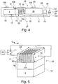
- FIG. 4 1 schematically shows an inhaler 27.
- the inhaler 27, here an electronic cigarette product comprises a housing 28 in which an air channel 30 is provided between at least one air inlet opening 31 and one air outlet opening 24 at a mouth end 32 of the cigarette product 27.
- the mouth end 32 of the cigarette product 27 designates the end at which the consumer pulls for the purpose of inhalation, thereby applying a negative pressure to the cigarette product 27 and generating an air flow 5 in the air channel 30.
- the cigarette product 27 advantageously consists of a base part 25 and a consumption unit 17, which comprises the evaporator unit 20 with the evaporator 3 and the liquid reservoir 18 and is designed in particular in the form of an exchangeable cartridge.
- a post-heating device 10 is provided in the inhaler 27.
- the reheating device 10 is at least partially disposed in the consumption unit 17.
- the post-heating device 10 may also be at least partially disposed in the base part 25.
- the air drawn in through the inlet opening 31 is conducted in the air channel 30 to or along at least one evaporator unit 20, wherein the evaporator unit comprises at least one evaporator 3, 3a, 3b, 3c, 3d.
- This in FIG. 4 Example shown advantageously comprises an arrangement 1 according to one of the in FIGS. 1 to 3 shown embodiments.
- the evaporator unit 20 in FIG. 4 is connected or connectable with at least one liquid reservoir 18 in which at least one liquid 2 is stored.
- the evaporator unit 20 evaporates liquid 2, which is supplied to it from the liquid reservoir 18, and outputs the vaporized liquid as aerosol / vapor on an outlet side 64 in the air stream 5 to.
- An advantageous volume of the liquid reservoir 18 is in the range between 0.1 ml and 5 ml, preferably between 0.5 ml and 3 ml, more preferably between 0.7 ml and 2 ml or 1.5 ml.
- the stored in the liquid reservoir 18 The liquid 2 to be metered is, for example, a mixture of 1,2-propylene glycol, glycerol, water, at least one flavor and / or at least one active ingredient, in particular nicotine and / or a medicinal active substance.
- the electronic cigarette 27 further comprises an electrical energy storage 26 and an electronic control device 29.
- the energy storage 26 is usually arranged in the base part 25 and can in particular a disposable electrochemical battery or a rechargeable electrochemical battery, such as a lithium-ion battery , his.
- the electronic control device 29 comprises at least one digital data processing device, in particular microprocessor and / or microcontroller, in the base part 25 (as in FIG FIG. 4 shown) and / or in the consumption unit 17.
- the consumption unit or cartridge 17 advantageously comprises a nonvolatile data memory for storing information or parameters concerning the consumption unit or cartridge 17.
- the data memory may be part of the electronic control device 29.
- the data memory is advantageous information about the composition of the liquid stored in the liquid storage 18, information on the process profile, in particular power / temperature control; Data for condition monitoring or system testing, for example leak testing; Data on copy protection and anti-counterfeiting security, an ID for unique identification of the consumer unit or cartridge 17, serial number, date of manufacture and / or expiration date, and / or number of trains (number of inhalation trains by the consumer) or the time of use stored.
- the data memory is advantageously connected via contacts and / or lines to the control device 29 or connectable.
- the inhaler 27 advantageously comprises a sensor, for example a pressure or flow sensor or a flow measuring arrangement 100 or a pressure or flow switch, wherein in particular the control device 29 can determine on the basis of a sensor signal issued by the sensor or switch that a consumer on The mouth end 32 of the cigarette product 27 pulls to inhale.
- the control device 29 controls the evaporator unit 20 in order to add liquid 2 from the liquid reservoir 18 as aerosol / vapor 6 into the air stream 5.
- At least one actuating element 101 is advantageously provided on the housing 28, see FIG. 4 ,
- the actuator 101 may be, for example, one or more switches, buttons, finger pressure gauge.
- electronic and / or capacitive actuators 101 are conceivable.
- the actuating element 101 can be set up, for example, for metering the aroma and / or active substances, in particular nicotine, and / or for adjusting the draw resistance.
- the actuator 101 is advantageously arranged and arranged to be operable by consumers by a finger pressure and / or by an oral force.
- the actuating element 101 is advantageously designed as a finger pressure-force-sensitive sensor 106 and / or a mouth-pressure-force-sensitive sensor 107.
- the actuating element 101 is advantageously arranged on a tube extending between the mouth end 32 and a distal end of the housing 28 tube and as Mundtikkraftsensitiver sensor or Mundpresskraftsensor 107, the actuator 101 is advantageous at the mouth end 32 of the housing 28 for the perception of the touch Lips of the consumer arranged.
- the measurement of the tensile strength or of the suction pressure can advantageously be the switching of bypasses 109 or other air ducts (not shown in the embodiment) and / or the adjustment of Chokes 14 or diaphragms in one or more air channels 30 allow.
- the consumer or user can advantageously control the evolution of steam or the air flow 5 with the aerosol 6, in particular the mass flow and / or the temperature, in an intuitive manner.
- the amount of evaporation is advantageously adjustable by the actuating element 101 with a force sensor 106 in the gripping region of the inhaler 27 for measuring the pressing force of the fingers.
- the evaporator power P of the evaporator 3, the steam rate of which is variable can be adapted to the grip strength on the basis of a time-resolved measurement of the actuation or gripping strength of the actuation element 101.
- the duty cycle and / or the temperature of the evaporator 3 is adjustable to adjust the flavor and / or active ingredient, in particular the nicotine content in the aerosol 6 or in the vapor phase based on the time-resolved measurement of the actuating element 101 to the grip strength.
- the evaporation amount and / or the aroma and / or active substance content, for example the nicotine content, are advantageously controllable by the user through a plurality of independent, preferably intuitive, methods, in particular the determination of the suction pressure with the flow measuring arrangement 100 and the actuation of the actuating element 101 ,
- the flow measuring arrangement 100 or the pressure or flow sensor can be provided as an input element for the electronic control device 29.
- the electronic control device 29 is adapted to be able to adjust the duty cycle and / or the temperature of the evaporator 3 advantageously sufficiently fast to the flavor and / or active ingredient, in particular the nicotine content, in the aerosol 6 or in the vapor phase and the vapor rate or
- the mass flow advantageously sufficiently fast, ie during a train, and to be able to adjust independently and / or advantageously sufficient to respond quickly to a time-resolved measurement of the measuring arrangement 100 and / or the operating element 101.
- reheating devices 10 are advantageously connected to the control device 29.
- the throttle 14, air guide elements 23 and / or orifices may be adjustable to change flow conditions on the evaporator 3 and / or a measuring channel and / or bypasses or secondary air channels on or off.
- a plurality of evaporator units 20 and / or evaporators 3, 3a, 3b, 3c, 3d may be provided in the air duct 30 or a plurality of air ducts.
- a plurality of air streams 5 is guided through a plurality of air ducts 30, wherein each of the air ducts 30 can be activated or opened by a throttle 14 or diaphragm and can be deactivated or closed. That an airflow 5 can be guided through an active or open air duct 30, and an inactive or closed air duct 30 can not be passed for an airflow 5.
- Each evaporator unit 20 and / or each evaporator 3, 3a, 3b, 3c, 3d is arranged such that aerosol 6 can be admitted to at least one of the air ducts 30.
- the sum of all air flows 5 flowing through the air ducts 30 is directed to the mouth end 32.
- a channel-by-channel activation of the evaporators 3, 3a, 3b, 3c, 3d and / or evaporator unit 20 that the evaporators 3, 3a, 3b, 3c, 3d rapidly, for example in less than 1 s, preferably Less than 0.2 s, the evaporation can begin and / or end to the withdrawal of the consumer and / or another control to be able to respond appropriately or to allow a direct response to the user request.
- the evaporation rate or the mass flow can be adjusted with an advantageously low response delay for the change of the evaporation properties.
- the response delay is dependent on the design of the evaporator 3, 3a, 3b, 3c, 3d, in particular the choice of material, geometry and the thermal coupling to the environment, with micromechanical systems are advantageous due to their low heat capacity and preferably high thermal conductivity.
- a user-controlled adaptation of the air flow 5, in particular of the mass flow, the aroma and / or active substances and / or the temperature can be made possible by a fast reaction time of the evaporator 3.
- the evaporation is advantageously adjustable with an adjustment of the evaporator temperature, the number of activated or controlled areas of the evaporator unit 20 or of the evaporator or evaporators 3, 3a, 3b, 3c, 3d, an adjustment of the pulse duty factor with pulsed control and / or a combination thereof.
- the mass flow, the temperature differences .DELTA.T before and after the evaporator 3, 3a, 3b, 3c, 3d and / or optionally the temperature differences .DELTA.T before and after the reheating device 10, the amount of steam and the aroma and / or active ingredient content, in particular the nicotine content, be varied independently or be variable.
- a display device 102 is advantageously provided, which may include, for example, one or more LEDs, displays of organic light emitting diodes (OLED) and / or liquid crystal displays (LC displays).
- OLED organic light emitting diodes
- LC displays liquid crystal displays
- the display device 102, the Setting, in particular the amount of steam, temperature and / or the flavor and / or active ingredient content represent.
- the evaporator unit 20 comprises a block-shaped, preferably monolithic, heating element or evaporator 3 made of an electrically conductive material, preferably doped silicon, doped ceramics, metal ceramics, filter ceramics, semiconductors, in particular germanium, graphite, semimetal and / or metal. It is not necessary that the entire evaporator 3 is made of an electrically conductive material. It may be sufficient, for example, that the surface of the evaporator 3 is electrically conductive, for example metallic, coated. In this case, the entire surface need not be coated, for example, conductor tracks may be provided on a non-conductive base body.
- the evaporator 3 is provided with a plurality of microchannels 62 which fluidly connect an inlet side 61 of the evaporator 3 with an outlet side 64.
- the inlet side 61 is liquid-conductively connected to the liquid reservoir 18 via a wick structure 19.
- the wick structure 19 serves for the passive delivery of liquid from a liquid reservoir 18 to the evaporator 3 by means of capillary forces.
- the wick structure 19 serves to distribute liquid uniformly, to be temperature-resistant and to form with their relatively small pores and / or thin capillaries a kind of check valve to unwanted backflow of bubble-containing liquid from the evaporator 3 in the Wick structure 19 and / or in the liquid storage 18 to prevent.
- the mean diameter of the microchannels 62 is preferably in the range between 5 ⁇ m and 200 ⁇ m, more preferably in the range between 30 ⁇ m and 150 ⁇ m, even more preferably in the range between 50 ⁇ m and 100 ⁇ m. Due to these dimensions, a capillary action is advantageously produced so that liquid entering the microchannel 62 at the inlet side 61 rises upwards through the microchannel 62 rises until the microchannel 62 is filled with liquid.
- the volume ratio of microchannels 62 to evaporator 3, which may be referred to as the porosity of the evaporator 3, is for example in the range between 10% and 50%, advantageously in the range between 15% and 40%, more preferably in the range between 20% and 30 %, for example 25%.
- the edge lengths of the surfaces provided with microchannels 62 of the evaporator 3 are for example in the range between 0.5 mm and 3 mm, preferably between 0.5 mm and 1 mm.
- the dimensions of the surfaces of the evaporator 3 provided with microchannels 62 may be, for example, 0.95 mm ⁇ 1.75 mm or 1.9 mm ⁇ 1.75 mm or 1.9 mm ⁇ 0.75 mm.
- the edge lengths of the evaporator 3 may be, for example, in the range between 0.5 mm and 5 mm, preferably in the range between 0.75 mm and 4 mm, more preferably in the range between 1 mm and 3 mm.
- the area of the evaporator 3 (chip size) may be, for example, 1 mm ⁇ 3 mm, 2 mm ⁇ 2 mm or 2 mm ⁇ 3 mm.
- the width b of the evaporator 3 is preferably in the range between 1 mm and 5 mm, more preferably in the range between 2 mm and 4 mm, and is for example 3 mm.
- the height h of the evaporator 3 is preferably in the range between 0.05 mm and 1 mm, more preferably in the range between 0.1 mm and 0.75 mm, even more preferably in the range between 0.2 mm and 0.5 mm, and is for example 0.3 mm.
- the number of microchannels 62 is preferably in the range between four and 1000. In this way, the heat input into the microchannels 62 can be optimized and realize a secure high evaporation performance and a sufficiently large steam outlet surface.
- the microchannels 62 are arranged in the form of a square, rectangular, polygonal, round, oval or other shaped array.
- the Array may be in the form of a matrix with s columns and z rows, where s advantageously in the range between 2 and 50 and more advantageously in the range between 3 and 30 and / or z advantageously in the range between 2 and 50 and more advantageously in the range between 3 and 30 lies. In this way, an effective and easily manufacturable arrangement of the microchannels 62 can be realized with a reliably high evaporation rate.
- the cross-section of the microchannels 62 may be square, rectangular, polygonal, round, oval or otherwise shaped, and / or may change in sections in the longitudinal direction, in particular increase, decrease or remain constant.
- the length of one or each microchannel 62 is preferably in the range between 100 ⁇ m and 1000 ⁇ m, more preferably in the range between 150 ⁇ m and 750 ⁇ m, even more preferably in the range between 180 ⁇ m and 500 ⁇ m and is for example 300 ⁇ m. In this way, an optimal fluid intake and portion formation can be realized with sufficiently good heat input from the evaporator 3 into the microchannels 62.
- the distance between two microchannels 62 is preferably at least 1.3 times the clear diameter of a microchannel 62, the distance being based on the central axes of the two microchannels 62.
- the distance may preferably be 1.5 to 5 times, more preferably 2 to 4 times the clear diameter of a microchannel 62. In this way, an optimal heat input into the microchannels and a sufficiently stable arrangement and wall thickness of the microchannels can be realized.
- the evaporator unit 20 has a preferably controlled by the control device 29 Studwoodsttle 71, which is connected via electrodes 72 on opposite sides of the evaporator 3 with this, so that a generated by the Schuwoodsttle 71 electrical Voltage Uh leads to a flow of current through the evaporator 3. Due to the ohmic resistance of the electrically conductive evaporator 3, the flow of current leads to a heating of the evaporator 3 and therefore to an evaporation of liquid contained in the microchannels 62. Vapor / aerosol 6 produced in this way escapes to the outlet side 64 from the microchannels 62 and is admixed with the air stream 5, see FIG.
- the controller 29 controls the heating voltage source 71, by spontaneously heating the liquid in the form of vapor / aerosol 6 in the microchannels 62 from the microchannels 62.
- the duration of the individual evaporation steps at different temperatures and / or evaporation of the individual components of the individual portions of the liquid can be kept so short and / or clocked with a drive frequency that the gradual evaporation of a consumer not perceived and still a largely homogeneous , tasteful, repeatable precise aerosol formation can be guaranteed.
- evaporation of a lower-boiling component of the liquid in a first evaporation interval at a first temperature A and then evaporation of a higher-boiling component of the liquid in a second evaporation interval at a second temperature B, which exceeds the temperature A are advantageous.
- the temperature has an influence, since the different liquid constituents have a different vapor pressure and their relative ratio in the vapor phase is dependent on the temperature.
- a voltage curve Uh (t) adapted to the liquid mixture used is stored in the data memory of the inhaler 27.
- the evaporation temperature is preferably in the range between 100 ° C and 400 ° C, more preferably between 150 ° C and 350 ° C, even more preferably between 190 ° C and 290 ° C.
- a porous and / or capillary, liquid-conducting wick structure 19 is advantageously arranged on the inlet side 61 of the evaporator 3.
- the wick structure 19 contacts the inlet side 61 of the evaporator 3 in a planar manner and covers all the microchannels 62 on the inlet side, as in FIGS FIG. 5 is apparent.
- the wick structure is liquid-conductively connected to the liquid reservoir 18.
- the in the FIGS. 4 and 5 shown direct connection of the liquid reservoir 18 to the wick structure 19 is only to be understood as an example.
- a liquid interface and / or a plurality of liquid lines between liquid reservoir 18 and wick structure 19 may be provided.
- the liquid reservoir 18 can therefore also be arranged at a distance from the wick structure 19.
- the liquid reservoir 18 may be larger in size than the wick structure 19.
- the wick structure 19 may be inserted, for example, in an opening of a housing of the liquid reservoir 18. It is also possible for a plurality of evaporator units 20 to be assigned to a liquid reservoir 18.
- the wick structure 19 may generally be in one or more parts.
- the wick structure 19 is made of porous and / or capillary material which, due to capillary forces, is capable of passively pumping liquid vaporized from the evaporator 3 in sufficient quantity from the liquid storage 18 to the evaporator 3 to empty the microchannels 62 and out therefrom prevent resulting problems.
- the wick structure 19 is advantageously made of a non-conductive material to prevent unwanted heating of liquid in the wick structure 19 by current flow.
- wick structure 19 is made of a conductive material, which is not excluded, between the wick structure 19 and the evaporator 3 is advantageously an insulating layer of an electrically and / or thermally insulating material, such as glass, ceramic or plastic, with extending through the insulating layer provided with the microchannels 62 corresponding through holes.
- the wick structure 19 advantageously consists of one or more of the materials cotton, cellulose, acetate, glass fiber fabric, glass fiber ceramic, sintered ceramic, ceramic paper, alumosilicate paper, metal foam, metal sponge, another heat-resistant, porous and / or capillary material with a suitable delivery rate, or a Composite of two or more of the aforementioned materials.
- the wick structure 19 may comprise at least one ceramic fiber paper and / or a porous ceramic.
- the volume of the wick structure 19 is preferably in the range between 1 mm 3 and 10 mm 3 , more preferably in the range between 2 mm 3 and 8 mm 3 , even more preferably in the range between 3 mm 3 and 7 mm 3 and is for example 5 mm 3 ,
- the evaporator 3 can advantageously be produced from sections of a wafer with thin-film technology, which has a layer thickness of preferably less than or equal to 1000 .mu.m, more preferably less than or equal to 750 .mu.m, even more preferably less than or equal to 500 .mu.m. Surfaces of the evaporator 3 may advantageously be hydrophilic.
- the inlet side 61 and / or the outlet side 64 of the evaporator 3 can advantageously be microstructured or have micro-grooves.
- the evaporator unit 20 is adjusted so that an amount of liquid preferably in the range between 1 ul and 20 ul, more preferably between 2 ⁇ l and 10 ⁇ l, more preferably between 3 ⁇ l and 5 ⁇ l, typically 4 ⁇ l per puff of the consumer.
- the evaporator unit 20 may be adjustable with respect to the amount of liquid / vapor per train.
- the inhaler 27 advantageously comprises a flow-through measuring arrangement 100 for measuring the air volume flow flowing through the inhaler.
- the measuring arrangement or flow measuring arrangement 100 measures the flow rate of the air flow 5 or a measuring air flow 105 through the air duct 30 or a measuring air duct 104 on a thermal basis or according to the heating principle, the air flow 5 is heated by a heater 63 by a temperature difference .DELTA.T.
- the heating device 63 may be formed, for example, by an evaporator 3 or a reheating device 10.
- the thermal behavior of the evaporator 3 and / or the post-heating device 10, in particular a silicon heater, is used.
- the measuring method according to the heating principle can therefore be combined with the post-heating of the air stream 5 by the reheating device 10.
- the heater 63 is provided in addition to, and independently of, the evaporator 3 and the reheat devices 10, allowing a more accurate flow measurement.
- the air stream 5 flowing through the air channel 3 passes through a plurality of temperature sensors 52, 53 for measuring the temperature of the air passing through the respective temperature sensor 52, 53.
- the temperature sensors 52, 53 are spaced apart in the flow direction, that is, arranged sequentially.
- An upstream temperature sensor 52 is connected upstream of the heater 63, that is, disposed upstream of the heater 63.
- a downstream temperature sensor 53 is the Heating device 63 downstream, that is arranged downstream of the heater 63.
- the temperature sensors 52, 53 output measurement temperature signals to an evaluation circuit 51 and / or the electronic control device 29 of the inhaler 27.
- an evaluation circuit 51 is provided for determining the temperature difference ⁇ T between the temperatures measured with the temperature sensors 52, 53.
- this evaluation can also be carried out in the electronic control device 29, so that a separate evaluation circuit 51 can be dispensable.
- the heating device 63 heats the air flow 5 in the air duct 30 with an electric heating power P.
- the measuring arrangement or flow measuring device 100 preferably comprises a wattmeter 103 for measuring the power P generated by the heater 103 and delivered to the air flow 5 be separate circuit.
- the heating power from an electronic control unit for the heater 63 may be known and transmitted to the electronic control device 29.
- the Wattmeter 103 can thus be realized in an electronic control unit for the heater 63 and / or in the electronic control device 29.
- the heat supplied to the air stream 5 increases its temperature.
- the upstream temperature sensor 52 is used to measure the temperature of the air stream 5 upstream of the evaporator 3 or in the air stream 5 before heating by the heater 63.
- the downstream temperature sensor 53 is used to measure the temperature of the air stream 5 downstream of the heater 63 and in the air stream 5 after the Heating by the heater 63.
- the volumetric flow of the air flow 5 through the air duct 30 depends on the mass flow by a known function or a proportionality constant, which can be determined, for example, by calibration and stored in the electronic control device 29, and can easily be determined by the electronic control device 29 as required.
- both temperature sensors 52, 53 and the heating device 63 of the flow-through measuring arrangement 100 are arranged in front of the first evaporator 3 or in a measuring channel 104 provided as by-pass 109, such as in FIG FIG. 4 or in FIG. 7 shown.
- the thermal capacity of air without vapor or aerosol can be used as heat capacity c, which increases the accuracy of the measurement.
- the flow measuring arrangement 100 is arranged completely or partially behind the first evaporator 3. This is the case in particular when the heating device 63 is formed by an evaporator 3 and / or a post-heating device 10. In this case, the thermal capacity of the air / vapor / aerosol mixture is assumed to be the heat capacity c.
- the flow rate measuring arrangement 100 is set up for the time-resolved measurement of the tensile strength by the user.
- the evaporator capacity of the evaporator 3, the steam rate of which can be varied can be adapted to the tensile strength of the consumer on the basis of the time-resolved measurement.
- the duty factor and / or the temperature of the evaporator 3 can advantageously be adjusted in order to adapt the flavor and / or active substance content, in particular the nicotine content, in the aerosol 6 or in the vapor phase to the tensile strength on the basis of the time-resolved measurement of the measuring arrangement 100.
- the flow rate measuring arrangement 100 can be used to activate the inhaler 27 by activating the inhaler 27, for example when the consumer blows, in order to ensure error-free detection activation by the consumer.
- the control device 29 may convert the consumer's puffing into a control signal for, for example, the evaporator unit 20, for example, to set a predetermined amount of steam by a certain blow.
- the inhaler 27 can be adjustable, controllable or controllable exclusively by bubbles measured by the flow rate measuring arrangement 100 or pressure or flow sensors and / or dragging by the user, so that switches, push buttons or the like can be dispensed with.
- a long bubble may mean calling up an adjustment menu, wherein one or more settings can be changed by briefly blowing and / or briefly pulling.
- the adjustment can be completed, for example, by a further long blowing and / or after a defined time.
- the evaporation amount is therefore advantageously controllable or controllable by the draw resistance or by the suction pressure applied by the consumer.
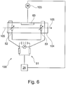
- FIG. 7 shows an inhaler 27, which in view of the differences from the in FIG. 4 illustrated embodiment will be explained.
- the in FIG. 7 shown inhaler 27 includes a bypass channel or secondary air passage 109.
- the flow measuring device 100 ie, the downstream temperature sensor 53, possibly the upstream temperature sensor 52 and / or the heater 63
- the flow measuring device 100 in the bypass channel or secondary air passage 109 is advantageous without evaporator. 3 arranged.
- This has as well as the in FIG. 4 arrangement shown has the advantage that the flow measurement is not affected by the vapor / aerosol content in the air stream 5 and measuring air flow 105.
- the bypass channel 109 is at least partially different from the air channel 30 channel.
- a branch 110 is provided upstream of the evaporator 3 or between the inlet opening 31 and the evaporator 3, at which the bypass channel 109 and separate the air duct 30.
- the bypass channel 109 and the air channel 30 extend parallel to each other up to a node 111, where they advantageously together form a common air flow, which is guided to the air outlet opening 24 and in particular can be inhaled by the consumer.
- the bypass channel 109 advantageously serves to bypass the evaporator unit 20 or the evaporator 3.
- the bypass passage 109 may advantageously comprise an orifice 108 or a valve, the orifice 108 being adapted to close or open the bypass passage 109, i. make the bypass channel 109 passable or impassable for airflow.
- the flow conditions at the at least one evaporator can be regulated and / or the flow resistance in the inhaler 27 can be influenced.
- throttle 14 for example, arranged to control the flow resistance in the bypass channel.
- bypass channel 109 forms the in FIG. 6 shown measuring channel 104, which leads the measuring air flow 105 for flow measurement with the flow measuring device 100.
- FIG. 8 shows a multi-channel evaporator unit 20 with a plurality, here four, evaporators 3a, 3b, 3c, 3d.
- the evaporators 3a, 3b, 3c, 3d separately heated or controlled, which allows a fast reaction time of the evaporation performance of the evaporator unit 20.
- the evaporators 3a, 3b, 3c, 3d may be connected to one or more liquid reservoirs 18 and / or connectable.
- two of the evaporators 3a, 3b, 3c, 3d vaporize different liquids 2 with different aroma and / or active ingredients and add it to the air stream 5.
- Individual evaporators 3a, 3b, 3c, 3d ( FIG. 8 Alternatively, individual evaporator chips and / or regions of an evaporator 3 can advantageously be controlled separately from one another, in particular switched on and off, ie activated.
- the amount of steam or the mass flow can be adjusted or regulated by the drive pulses and / or with the constellation of the driven evaporators 3a, 3b, 3c, 3d or regions of an evaporator 3.
- a gradation in the control of the control of the evaporator 3 or areas of an evaporator 3 may be provided, in which various modes are conceivable.
- two evaporators 3a, 3b for a weak or little evaporation, two evaporators 3a, 3b, for a standard amount or average amount of three evaporators 3a, 3b, 3c and for a strong or a lot of evaporation four evaporators 3a, 3b, 3c, 3d, or alternatively regions of an evaporator 3rd , be activated.
Landscapes
- Health & Medical Sciences (AREA)
- Engineering & Computer Science (AREA)
- Life Sciences & Earth Sciences (AREA)
- Hematology (AREA)
- Animal Behavior & Ethology (AREA)
- Anesthesiology (AREA)
- Biomedical Technology (AREA)
- Heart & Thoracic Surgery (AREA)
- Veterinary Medicine (AREA)
- Public Health (AREA)
- General Health & Medical Sciences (AREA)
- Bioinformatics & Cheminformatics (AREA)
- Pulmonology (AREA)
- General Physics & Mathematics (AREA)
- Fluid Mechanics (AREA)
- Physics & Mathematics (AREA)
- Biophysics (AREA)
- Medicinal Preparation (AREA)
- Acyclic And Carbocyclic Compounds In Medicinal Compositions (AREA)
Abstract
Description
- Die vorliegende Erfindung betrifft eine Anordnung für einen Inhalator, umfassend mindestens einen elektrischen Verdampfer zum Verdampfen von dem Verdampfer zugeführter Flüssigkeit und zur Zugabe der verdampften Flüssigkeit zu einem durch den Inhalator strömenden Luftstrom zur Bildung eines Aerosols, und eine Durchfluss-Messanordnung zur Messung des Volumen- und/oder Massenstroms des durch den Inhalator strömenden Luftstroms. Die vorliegende Erfindung betrifft außerdem ein Basisteil für einen Inhalator und einen Inhalator.
- Im Stand der Technik ist eine Vielzahl von Inhalatoren beziehungsweise elektronischer Zigarettenprodukte mit einer solchen Anordnung bekannt.
- Übliche Inhalatoren, beispielsweise elektronische Zigarettenprodukte, werden beispielsweise durch einen Unterdruckschalter aktiviert. Sobald der Nutzer durch ziehen an einem Mundende des Inhalators einen Unterdruck relativ zum Umgebungsdruck erzeugt, wird die Verdampfung der Flüssigkeit aktiviert und diese dem Luftstrom als Aerosol beziehungsweise Dampf zugegeben. Die Flüssigkeit umfasst Aroma- und/oder Wirkstoffe, insbesondere Nikotin, die dem Nutzer mit dem Aerosol beziehungsweise dem Dampf verabreicht werden. Gerät der Unterdruck unter eine Schaltschwelle, wird die Verdampfung beendet. Der Verdampfungsvorgang ist somit unabhängig von der Stärke des erzeugten Unterdrucks, solange die Schaltschwelle über- oder unterschritten ist.
- Der Konsument einer konventionellen Zigarette erwartet jedoch ein anderes Verhalten. Bei einer konventionellen Zigarette kann über die Stärke des Zuges die Verbrennung des Tabaks beziehungsweise des Tabakproduktes und somit die Aufnahme von Rauch gesteuert werden. Eine solche Möglichkeit wäre auch für ein elektronisches Zigarettenprodukt beziehungsweise einen Inhalator wünschenswert.
- Um der Stärke des Zuges des Konsumenten Rechnung zu tragen, weisen Inhalatoren gemäß dem Stand der Technik Durchfluss-Messanordnungen zur Messung des Volumen- und/oder Massenstroms des durch den Inhalator strömenden Luftstroms auf, siehe beispielsweise
DE 10 2009 029 768 B4 . Der Nachteil der bekannten Messanordnungen ist die Einschränkung der Messbereiche. Die Unterdruckschalter arbeiten lediglich bei vergleichsweise starken Unterdrücken zuverlässig, während die Durchfluss-Messanordnungen vorrangig bei vergleichsweise kleinen Unterdrücken, Druckdifferenzen beziehungsweise Strömungsgeschwindigkeiten zuverlässig arbeiten. Ferner sind bekannte mechanische Elemente umfassende Durchfluss-Messanordnungen wie Flügelrad-Anemometer, siehe beispielsweiseEP 2 563 172 B1 , aufwendig, teuer und anfällig für Verschmutzungen und eignen sich nur bedingt zur Erfassung absoluter Messwerte, beispielsweise zum Einschalten des Inhalators. - Die Aufgabe der Erfindung besteht darin, eine Anordnung für einen Inhalator bereitzustellen, der eine verbesserte und zuverlässige Durchflussmessung erlaubt.
- Die Erfindung löst diese Aufgabe mit den Merkmalen der unabhängigen Ansprüche.
- Erfindungsgemäß wird vorgeschlagen, dass die Durchfluss-Messanordnung eine Heizeinrichtung, einen stromabwärts der Heizeinrichtung angeordneten nachgeschalteten Temperatursensor zur Messung einer Luftausgangstemperatur und eine elektronische Steuerungsvorrichtung umfasst, und die elektronische Steuerungsvorrichtung zur Ermittlung des Volumen- und/oder Massenstroms des durch den Inhalator strömenden Luftstroms auf der Grundlage einer Temperaturdifferenz zwischen der Luftausgangstemperatur und einer Lufteingangstemperatur des Luftstroms stromaufwärts der Heizeinrichtung eingerichtet ist.
- Die erfindungsgemäße Anordnung erlaubt eine genaue Durchflussmessung auf thermischer Grundlage. Die Lufteingangstemperatur ist eine stromaufwärts der Heizeinrichtung vorliegende Temperatur und entspricht beispielsweise der Umgebungstemperatur. Die Heizeinrichtung ist dazu eingerichtet, Luft auf die Luftausgangstemperatur zu erwärmen, wobei die erwärmte Luft dem stromabwärts der Heizeinrichtung angeordneten nachgeschalteten Temperatursensor zugeführt wird. Die Heizeinrichtung und/oder der Temperatursensor kann beispielsweise einen ohmschen Widerstand und/oder einen Thermistor, beispielsweise einen Heiß- oder Kaltleiter, umfassen.
- Die erfindungsgemäße Anordnung ist frei von mechanischen Teilen, die für die Durchflussmessung bewegt werden müssen und ist somit wenig anfällig für Verschmutzung.
- Die durch die Luft von dem Heizelement zum nachgeschalteten Temperatursensor transportierte Wärme gibt Aufschluss über den Massen- und/oder Volumenstrom, welcher mit der Luft transportiert wird. Anhand des Massen- und/oder Volumenstroms kann auf die Strömungsgeschwindigkeit, die Zugstärke beziehungsweise den Saugdruck geschlossen werden.
- Vorzugsweise umfasst die Durchfluss-Messanordnung einen stromaufwärts der Heizeinrichtung angeordneten vorgeschalteten Temperatursensor zur Messung der Lufteingangstemperatur des Luftstroms, um einen genauen Referenzwert für die Lufteingangstemperatur ermitteln und vorteilhaft die Temperaturdifferenz bestimmen zu können. Die Anordnung wenigstens zweier Temperatursensoren, wobei insbesondere einer der Temperatursensoren stromaufwärts der Heizeinrichtung und einer der Temperatursensoren stromabwärts der Heizeinrichtung angeordnet ist, erlaubt die beliebige Anordnung der Durchfluss-Messanordnung innerhalb des Inhalators. Auch die Anordnung der Durchfluss-Messanordnung nach dem Verdampfer ist denkbar, da die Temperaturdifferenz exakt und zuverlässig gemessen werden kann.
- In anderen Ausführungsformen kann auf den vorgeschalteten Temperatursensor verzichtet werden, wobei die Lufteingangstemperatur geschätzt oder anderweitig, beispielsweise über lokale Wetterinformationen, das Internet und/oder mit dem Inhalator informationstechnisch verbundenen Geräten, bereitgestellt werden kann.
- Vorteilhaft ist die Heizeinrichtung stromaufwärts von dem oder den Verdampfern des Inhalators angeordnet, um eine Temperatur mit dem oder den Temperatursensoren an Luft ohne zugegebene Flüssigkeit messen zu können. Dies erlaubt aufgrund der bekannten Wärmekapazität von Luft die vorteilhafte Ermittlung des Volumen- und/oder Massenstroms.
- Bevorzugt ist die Heizeinrichtung von einem der Verdampfer gebildet, um einen effektiven Aufbau der Durchfluss-Messanordnung mit nur wenigen Komponenten gewährleisten zu können.
- Die Erfindung stell des Weiteren eine Anordnung aufweisend mindestens einen elektrischen Verdampfer zum Verdampfen von dem Verdampfer zugeführter Flüssigkeit und zur Zugabe der verdampften Flüssigkeit zu einem durch den Inhalator strömenden Luftstrom zur Bildung eines Aerosols bereit, wobei die Anordnung erfindungsgemäß eine Nacherwärmungsvorrichtung zur Nacherwärmung des Aerosols umfasst, um eine höhere Dampfqualität zu erzielen.
- Die Nacherwärmungsvorrichtung ist vorteilhaft stromabwärts des Verdampfers und/oder in Bezug zu dem Verdampfer angeordnet, d.h. dass das Aerosol nach seiner Erzeugung durch Verdampfung der Flüssigkeit am Verdampfer mit der Nacherwärmungsvorrichtung nacherwärmbar bzw. warmhaltbar ist. Das Aerosol bzw. der Dampf beziehungsweise der Luftstrom mit der zugegebenen Flüssigkeit wird nach der Verdampfung der Flüssigkeit durch den Verdampfer mit der Nacherwärmungsvorrichtung erwärmt. Somit kann eine Kondensation vermieden werden und Aroma- und/oder Wirkstoffe, wie beispielsweise Nikotin, können im Aerosol bzw. Dampf zuverlässig von dem Luftstrom transportiert werden.
- Durch die Nacherwärmung kann die Tröpfchengröße beeinflusst und die Wirkung der Aroma- und/oder Wirkstoffe optimiert werden. Die Nacherwärmung des Luftstroms bzw. des Aerosols führt vorzugsweise dazu, dass die Luft für den Konsumenten angenehm warm wird und bereits kondensierte Tropfen des Aerosols nachverdampfen und/oder an der gegebenenfalls weiteren Kondensation gehindert werden. Der dem Konsumenten zugeführte Dampf ist somit feiner und weist eine höhere Dampfqualität auf.
- Die Heizeinrichtung kann vorteilhaft von der Nacherwärmungsvorrichtung gebildet sein.
- Vorzugsweise ist die elektronische Steuerungsvorrichtung zur Ermittlung des Volumen- und/oder Massenstroms des durch den Inhalator strömenden Luftstroms durch Anwendung der Gleichung Δm / Δt = P/(c·ΔT) eingerichtet, wobei Δ m / Δ t der Massenstrom, P die Heizleistung der Heizeinrichtung, ΔT die Temperaturdifferenz zwischen der Luftausgangstemperatur und der Lufteingangstemperatur und c die bekannte oder geschätzte Wärmekapazität der durch die Heizeinrichtung erwärmten Luft (je nach Anordnung der Heizeinrichtung mit oder ohne Aerosol) sind, um eine einfache und exakte Ermittlung des Massenstroms zu erlauben.
- Bevorzugt umfasst die Anordnung ein Wattmeter zur Ermittlung der Heizleistung P der Heizeinrichtung, um die erbrachte Heizleistung über ein Zeitintervall messen zu können und somit die der Luft und/oder dem Aerosol beziehungsweise Dampf zugeführten Wärme ermitteln zu können.
- Vorteilhaft ist die elektronische Steuerungsvorrichtung zur Steuerung des mindestens einen Verdampfers in Abhängigkeit der gemessenen Durchflussmenge des Luftstroms durch den Inhalator eingerichtet, um dem Konsumenten eine der Zugstärke beziehungsweise dem Saugdruck angepasste Verdampfung von Flüssigkeit und/oder Zugabe von Aroma- und/oder Wirkstoffen zum Luftstrom zu ermöglichen.
- Vorzugsweise ist der Verdampfer auf der Grundlage eines Signals von einem Betätigungselement steuerbar, um dem Konsumenten eine individuell einstellbare Verdampfung von Flüssigkeit und/oder Zugabe von Aroma- und/oder Wirkstoffen zum Luftstrom zu ermöglichen. Das Betätigungselement kann beispielsweise ein Mundpresskraftsensor, einen Fingerdruckkraftmesser, Schalter und/oder Taster umfassen. Insbesondere kann ein elektronisches und/oder kapazitives Betätigungselement am Mundende und/oder an einem sich zwischen dem Mundende und einem distalen Ende des Inhalators erstreckenden Tubus vorgesehen sein.
- In einer vorteilhaften Ausführungsform sind mindestens die Heizeinrichtung und der nachgeschaltete Temperatursensor in einem Messkanal angeordnet, um eine von der Verdampfung der Flüssigkeit unabhängige Durchflussmessung zu erlauben. Der Messkanal kann von dem Luftkanal beziehungsweise Hauptluftkanal, in welchem die Flüssigkeit als Aerosol zugegeben wird, wenigstens teilweise separat vorgesehen sein, beispielsweise als Bypass. Der Messkanal kann in einer Ausführungsform durch den Luftkanal bzw. einem Abschnitt des Luftkanals stromaufwärts des Verdampfers gebildet sein.
- Vorteilhaft ist der mindestens eine elektrische Verdampfer ein mehrkanaliger, insbesondere temperaturgesteuerter Verdampfer, um eine verbesserte und einfach regel- und/oder steuerbare Verabreichung von Aroma- und/oder Wirkstoffe zu ermöglichen. Ein mehrkanaliger Verdampfer kann beispielsweise von einer Verdampfereinheit mit einer Mehrzahl von Verdampfern und/oder mindestens ein Verdampfer mit einer Mehrzahl separat ansteuerbarer, heizbarer beziehungsweise aktivierbarer Bereiche gebildet sein.
- Vorteilhaft ist Verdampfungsmenge der verdampften Flüssigkeit, die Nikotinmenge der verdampften Flüssigkeit, die Temperatur des Verdampfers, der Tastgrad des Verdampfers und/oder die Anzahl der aktivierten Verdampfer und/oder Verdampferbereiche einstellbar, steuerbar und/oder regelbar, um eine hohe Aerosol- bzw. Dampfqualität bereitstellen zu können.
- Die Verdampfungsmenge, die Nikotinmenge, die Temperatur, der Tastgrad und/oder die Anzahl der aktivierten Verdampfer und/oder Verdampferbereiche kann durch den Konsumenten und/oder elektronisch einstellbar sein. Beispielsweise kann die Verdampfungsmenge, die Nikotinmenge, die Temperatur, der Tastgrad und/oder die Anzahl der aktivierten Verdampfer und/oder Verdampferbereiche abhängig von der Zusammensetzung der Flüssigkeit und/oder den Konsumgewohnheiten des Konsumenten einstellbar sein. Insbesondere ist die Temperatur und/oder der Tastgrad vorzugsweise über die Dauer eines Verdampfungsintervalls zeitweise steigend, zeitweise fallend und/oder zeitweise gleichbleibend.
- Die Verdampfungsmenge, die Nikotinmenge, die Temperatur, der Tastgrad und/oder die Anzahl der aktivierten Verdampfer und/oder Verdampferbereiche sind vorzugsweise unabhängig voneinander variierbar, was beispielsweise eine von der Dampfmenge unabhängige Konzentration von Aroma- und/oder Wirkstoffen ermöglicht.
- Vorzugsweise weist die Anordnung einen Kraftsensor zur Messung der Fingeranpresskraft oder der Mundpresskraft durch den Konsumenten auf, um eine einfache Einstellbarkeit des Inhalators durch den Konsumenten zu ermöglichen. Beispielsweise ist an einem Gehäuse des Inhalators ein Kraftsensor zur Messung der Fingeranpresskraft und/oder an dem Mundende des Inhalators ein Mundpresskraftsensor zur Messung der Mundpresskraft vorgesehen. Der Kraftsensor stellt vorzugsweise ein Signal zur Einstellung des Inhalators, insbesondere des Verdampfers, bereit und erlaubt somit die Aktivierung, Steuerung und/oder Regelung der Aroma- und/oder Wirkstoffverabreichung.
- Bevorzugt ist die Durchfluss-Messanordnung als Eingabeelement zur Eingabe von Information in die elektronische Steuerungsvorrichtung durch den Konsumenten nutzbar, um eine intuitive Steuerung und/oder Regelung des Inhalators zu ermöglichen.
- Vorteilhaft ist die Durchfluss-Messanordnung zur Feststellung von Pusten oder Ziehen in den Inhalator durch den Konsumenten als Eingabe eingerichtet, um insbesondere für das Inhalieren atypische Atmungsmuster, beispielsweise eine atypische Atemfrequenz und/oder ein atypisches Atemvolumen, als Eingabe zu kodieren.
- Vorzugsweise ist die Durchfluss-Messanordnung zur Aktivierung des Inhalators nutzbar, um eine unbeabsichtigte Aktivierung des Inhalators zu vermeiden. Beispielsweise kann in dieser Ausführungsform auf einen An-/Aus-Schalter oder ähnliches an der Außenseite des Gehäuses des Inhalators verzichtet werden.
- Bevorzugt ist die Durchfluss-Messanordnung zur Dampfmengeneinstellung durch den Konsumenten nutzbar, um beispielsweise die Dampfmenge an die Zugstärke des Konsumenten anpassen und ein Raucherlebnis wie bei einer herkömmlichen Zigarette ermöglichen zu können.
- In einer bevorzugten Ausführungsform ist eine Blende und/oder ein Bypasskanal zur Regelung der Strömungsverhältnisse an dem mindestens einen Verdampfer vorgesehen, um eine verbesserte Dampfqualität und/oder Durchflussmessung zu ermöglichen.
- In einer bevorzugten Ausführungsform ist der Verdampfer wenigstens teilweise siliziumbasiert, vorzugsweise ein Mikro-Elektro-Mechanisches System (MEMS), um einen effektiven und zuverlässigen Verdampfer bereitstellen zu können.
- Die Erfindung wird im Folgenden anhand bevorzugter Ausführungsformen unter Bezugnahme auf die beigefügten Figuren erläutert. Dabei zeigt
- Fig. 1
- einen Schnitt durch eine Anordnung mit einer Nacherwärmungsvorrichtung;
- Fig. 2
- einen Schnitt durch eine Anordnung mit mehreren Nacherwärmungsvorrichtungen;
- Fig. 3
- eine perspektive Ansicht einer Anordnung mit ringförmigen Wärmeleitelementen;
- Fig. 4
- eine schematische Darstellung eines Inhalators;
- Fig. 5
- eine perspektivische Querschnittsansicht einer Verdampfereinheit mit einem Flüssigkeitsspeicher; und
- Fig. 6
- eine schematische Darstellung einer Messanordnung zur Durchflussmessung;
- Fig. 7
- eine schematische Darstellung eines Inhalators; und
- Fig. 8
- eine schematische Darstellung einer Verdampfereinheit.
-
Figur 1 zeigt eine Anordnung 1 mit einer Nacherwärmungsvorrichtung 10. Die Anordnung 1 ist für einen inFigur 4 gezeigten Inhalator 27 vorgesehen. Der Konsument beaufschlagt die Anordnung 1 durch Ziehen an einem Mundende 32 des Inhalators 27 mit einem Unterdruck. Durch den Unterdruck tritt Luft an einem Einlassende 21 der Anordnung 1 in die Anordnung 1 ein und der Unterdruck bewirkt einen Luftstrom 5 durch die Anordnung 1 von dem Einlassende 21 zu einem Auslassende 22, sieheFigur 1 . - Die Anordnung 1 umfasst in diesem Beispiel zwei Verdampfer 3a, 3b, um eine Aroma- und/oder Wirkstoffe umfassende Flüssigkeit 2 zu verdampfen. Durch das Verdampfen wird dem Luftstrom 5 Aerosol 6 bzw. Dampf mit den Aroma- und/oder Wirkstoffen zugegeben. Das Aerosol 6 transportiert die von der Flüssigkeit 2 umfassten Aroma- und/oder Wirkstoffe in dem Luftstrom 5 zu dem, dem Mundende 32 zugeordneten Auslassende 22. Zwischen dem Einlassende 21 und dem Auslassende 22 erstreckt sich in der gezeigten Ausführungsform ein Luftkanal 30, durch welchen der Luftstrom 5 geleitet wird. Der Luftstrom 5 befördert das Aerosol 6 vorteilhaft durch den Luftkanal 30. Der Massenstrom Δm / Δt ist die Luftmasse bzw. Luft-/Aerosolmasse Δm, die innerhalb eines Zeitintervalls Δt durch den Luftkanal 30 strömt. Der (Luft-)Massenstrom beeinflusst das Raucherlebnis beziehungsweise die Verabreichung von Aroma- und/oder Wirkstoffen, welche im Aerosol 6 enthalten sind.
- Die Verdampfer 3a, 3b sind beispielsweise mit einer in dem Inhalator 27 vorgesehenen elektronischen Steuerungsvorrichtung 29 und/oder einem in dem Inhalator 27 vorgesehen Energiespeicher 26 zur Versorgung mit Energie verbunden. Die Verdampfer 3a, 3b beziehen zur Verdampfung und/oder Wärmeerzeugung vorteilhaft über einen definierten beziehungsweise definierbaren Zeitraum eine Leistung P. Die Verdampfer 3a, 3b bewirken, dass die Temperatur des Luftstroms 5 vorteilhaft stromabwärts eines jeden Verdampfers 3a, 3b höher ist als stromaufwärts des jeweiligen Verdampfers 3a, 3b, d.h. die Verdampfer 3a, 3b bewirken eine Temperaturdifferenz ΔT im Luftstrom 5.
- Die Verdampfer 3a, 3b sind entlang des Luftstroms 5 beziehungsweise in dem Luftkanal 30 in Strömungsrichtung hintereinander und voneinander beabstandet angeordnet, d.h. die Verdampfer 3a, 3b sind in Richtung des Luftstroms 5 sequenziell geschaltet. Die Verdampfer 3a, 3b können dazu eingerichtet sein, verschiedene Flüssigkeiten 2 und/oder Flüssigkeit 2 bei verschiedenen Temperaturen zu verdampfen.
- Die Flüssigkeit 2 ist in einem oder mehreren, hier beispielhaft zwei, Flüssigkeitsspeichern 18 gespeichert und kann durch eine zwischen dem jeweiligen Verdampfer 3a, 3b und dem entsprechenden Flüssigkeitsspeicher 18 über eine in
Figur 5 gezeigte Dochtstruktur 19 dem jeweiligen Verdampfer 3a, 3b zugeführt werden. In einer nicht gezeigten Ausführungsform kann die Anordnung 1 einen Verdampfer 3a, 3b und/oder einen Flüssigkeitsspeicher 18 umfassen. - In der in
Figur 1 gezeigten Ausführungsform ist den Verdampfern 3a, 3b eine Drossel 14 nachgeordnet, das heißt die Drossel 14 ist stromabwärts von den Verdampfern 3a, 3b angeordnet. Die Drossel 14 ist eine Verengung des Querschnitts des den Luftstrom 5 zur Verfügung stehenden Volumens. Die Drossel 14 bewirkt somit vorteilhaft eine Einstellung des Zugwiderstandes, des Massenstroms Δm / Δt des Luftstroms 5 durch den Luftkanal 30 und/oder eine Verwirbelung des Luftstroms 5. Die Verwirbelung des Luftstroms 5 kann gezielt genutzt werden, um den Wärmetransport innerhalb des Luftstroms 5 zu beeinflussen und/oder den Luftstrom 5 zu durchmischen, eine turbulente Strömung hervorzurufen bzw. eine laminare Strömung zu unterdrücken. Der so durch die Drossel 14 verbesserte Wärmetransport innerhalb des Luftstroms kann vorzugsweise die Rekondensation des Aerosols 6 und/oder Dampfes vermindern. - Die Drossel 14 ist vorteilhaft dazu eingerichtet, den Querschnitt des Luftkanals 30 zu verringern. Bevorzugt ist die durch die Drossel 14 bewirkte Veränderung des Querschnitts einstellbar. Beispielsweise kann an der Außenseite des Inhalators 27 eine den Konsumenten zugängige Einstellvorrichtung zur Einstellung des Querschnitts der Drossel 14 vorgesehen sein. Die Einstellvorrichtung kann beispielsweise ein Stellrad, Schalter, Taster und/oder Ähnliches umfassen.
- Die Drossel 14 und/oder der Zugwiderstand kann in einer Ausführungsform durch den Konsumenten mittels Blasen beziehungsweise Pusten und/oder Saugen beziehungsweise Ziehen einstellbar sein. Eine bestimmte Abfolge von Pusten und/oder Ziehen kann einen entsprechenden Zugwiderstand und/oder eine Einstellung der Drossel 14 kodieren. Die Einstellung der Drossel 14 kann an einer an der Außenseite des Inhalators 27 vorgesehenen Anzeigevorrichtung 102 darstellbar sein.
- Bevorzugt ist der Querschnitt der Drossel 14 elektrisch beziehungsweise elektronisch einstellbar. Die Drossel 14 kann beispielsweise ein oder mehrere piezoelektrisches oder induktiv gesteuerte Elemente 15 aufweisen, welche dazu eingerichtet sind, aufgrund elektrischer Signale den Querschnitt der Drossel 14 einzustellen. Die oder das piezoelektrische oder induktive Element 15 ist beziehungsweise sind so angeordnet, dass der Querschnitt des Luftkanals 30 beziehungsweise das dem Luftstrom 5 zur Verfügung stehende Volumen vorteilhaft aufgrund der elektrischen Signale oder deren Ausbleiben veränderlich ist. Beispielsweise kann ein piezoelektrisches oder induktives Element 15 den Luftstrom 5 quer zu der Strömungsrichtung beziehungsweise in Umfangsrichtung umgeben. In einer anderen Ausführungsform können mehrere piezoelektrische und/oder induktive Elemente 15 in Strömungsrichtung auf gleicher Höhe angeordnet sein, um eine Verengung des Querschnitts zu erreichen.
- Die Drossel 14 ist beispielsweise mit der in dem Inhalator 27 vorgesehenen elektronischen Steuerungsvorrichtung 29 zur Einstellung des Querschnitts der Drossel 14 verbunden.
- In einer weiteren Ausführungsform weist der Inhalator eine Mehrzahl von Luftkanälen 30 auf. Jeder der Luftkanäle 30 kann eine zugeordnete Drossel 14 aufweisen, wobei vorteilhaft jede Drossel 14 vollständig schließbar ist, um den Luftstrom 5 durch den jeweiligen Luftkanal 30 zu unterbinden. Jeder der Luftkanäle ist vorzugsweise einzeln aktivierbar beziehungsweise schaltbar um den Luftstrom 5 durch den jeweiligen Luftkanal 30 zu erlauben oder zu unterbinden. Das Unterbinden des Luftstroms 5 durch einen oder mehreren der Luftkanäle 30 und das Führen des Luftstroms 5 durch einen oder mehrere der Luftkanäle 30 bewirkt die zuverlässige Regulierung des Zugwiderstandes, des Massenstroms und der Aroma- und/oder Wirkstoffzugabe zum Gesamtluftstrom, der sich beispielsweise aus der Summe aller Luftströme 5 durch passierbare beziehungsweise aktivierte Kanäle zusammensetzt.
- In der in
Figur 1 gezeigten Ausführungsform ist stromabwärts der Drossel 14 eine Nacherwärmungsvorrichtung 10 angeordnet. Die Drossel 14 ist in diesem Beispiel in Strömungsrichtung zwischen den Verdampfern 3a, 3b und der Nacherwärmungsvorrichtung 10 angeordnet. Ein von der Drossel 14 vorteilhaft verwirbelter Luftstrom 5 trifft auf die Nacherwärmungsvorrichtung 10 und ermöglicht eine effektive Erwärmung des Luftstroms 5. - Die Nacherwärmungsvorrichtung 10 umfasst vorteilhaft ein Heizelement 16, welches dazu eingerichtet ist, den auf die Nacherwärmungsvorrichtung 10 treffenden Luftstrom 5 mit darin befindlichen Aerosol 6 bzw. Dampf zu erhitzen. Die Nacherwärmungsvorrichtung 10 ist vorteilhaft von dem Verdampfer 3 verschieden. Der Nacherwärmungsvorrichtung 10 ist vorteilhaft Flüssigkeit 2 nur über den Luftstrom 5 als Aerosol 6 und/oder Dampf zuführbar.
- Das Heizelement 16 ist beispielsweise mit der in dem Inhalator 27 vorgesehenen elektronischen Steuerungsvorrichtung 29 und/oder dem in dem Inhalator 27 vorgesehen Energiespeicher 26 zur Versorgung mit Energie verbunden. Das Heizelement 16 bezieht zur Wärmeerzeugung vorteilhaft über einen definierten beziehungsweise definierbaren Zeitraum eine Leistung P. Das Heizelement 16 bewirkt, dass die Temperatur des Luftstroms 5 stromabwärts des Heizelements 16 höher ist als stromaufwärts des Heizelements, d.h. das Heizelement 16 bewirkt eine Temperaturdifferenz ΔT im Luftstrom 5. Die Erhöhung der Temperatur des Luftstroms 5 durch das Heizelement 16 beziehungsweise durch die Nacherwärmungsvorrichtung 10 wirkt vorteilhaft einer Rekondensation des im Luftstrom 5 transportierten Aerosols 6 oder einem Niederschlag dessen am Luftkanal 30 und/oder anderer Komponenten des Inhalators entgegen.
- Die Anordnung 1 in
Figur 1 umfasst vorteilhaft Luftleitelemente 23, welche dazu eingerichtet sind, den Luftstrom 5 zu leiten und/oder zu verwirbeln. In dieser Ausführungsform umfassen die Luftleitelemente 23 eine Wegbiegung 8 des Luftstroms 5 bzw. des Luftkanals 30 und eine Luftleiteinrichtung 9, beispielsweise ausgebildet als eine Neigung beziehungsweise Anschrägung der Nacherwärmungsvorrichtung 10 bzw. des Heizelements 16 zur Strömungsrichtung. Die der Nacherwärmungsvorrichtung 10 zugeordnete Luftleiteinrichtung 9 bewirkt, dass der Luftstrom 5 unter einem Winkel zwischen 10° und 80°, vorteilhaft zwischen 20° und 70°, vorzugsweise zwischen 30° und 60°, besonders bevorzugt zwischen 40° und 50°, beispielsweise von 45° auf die Nacherwärmungsvorrichtung 10 trifft und die Nacherwärmungsvorrichtung 10 somit den Luftstrom 5 effektiv erwärmen kann. - Vorteilhaft ist die Heiztemperatur des oder der Verdampfer 3 und/oder der Nacherwärmungsvorrichtung 10 unter Berücksichtigung unterschiedlicher Dampfphasen der Bestandteile der Flüssigkeit 2 beziehungsweise des Aerosols 6 einstellbar, steuerbar und/oder regelbar. Bei einer gepulsten Ansteuerung beziehungsweise Beheizung des Verdampfers 3 und/oder der Nacherwärmungsvorrichtung 10 ist eine Anpassung des Tastgrades zur definierten Leistungs- beziehungsweise Wärmeabgabe vorgesehen. Vorteilhaft ist die von dem Verdampfer 3 und/oder der Nacherwärmungsvorrichtung 10 hervorgerufene Temperaturänderung ΔT und/oder die Leistung P einstellbar, um eine hohe Qualität der Zusammensetzung des Aerosols 6 zu ermöglichen.
-
Figur 2 zeigt eine Anordnung 1 mit mehreren in Strömungsrichtung hintereinander angeordneten Nacherwärmungsvorrichtungen 10. Die gezeigte Ausführungsform wird anhand der Unterschiede zu der Ausführungsform ausFigur 1 erläutert. Die Nacherwärmungsvorrichtungen 10 umfassen jeweils mindestens ein Heizelement 16a, 16b, 16c. Die Heizelemente 16a, 16b, 16c sind in Strömungsrichtung hintereinander und voneinander beabstandet angeordnet. Jedes der Heizelemente 16a, 16b, 16c erwärmt den Luftstrom mit einer Leistung Pi, wobei die Leistung Pi für jedes der Heizelemente 16a, 16b, 16c individuell sein kann, insbesondere individuell für jedes Heizelement 16a, 16b, 16c einstellbar, in Strömungsrichtung steigend und/oder fallend. - Dem in Strömungsrichtung ersten Verdampfer 3a ist eines der Heizelemente 16a gegenüberliegend angeordnet, d.h. das Heizelement 16a ist wenigstens teilweise dem Verdampfer 3a zugewandt und ist quer zur Strömungsrichtung auf der gegenüberliegenden Seite im Luftkanal 30 angeordnet. Stromabwärts von dem ersten Verdampfer 3a ist ein zweiter Verdampfer 3b angeordnet, welchem gegenüber ein weiteres der Heizelemente 16b angeordnet ist. Stromabwärts der Verdampfer 3a, 3b und der Drossel 14 ist ein weiteres der Heizelemente 16c angeordnet. Die Nacherwärmungsvorrichtungen 10 und die Heizelemente 16a, 16b, 16c sind in Strömungsrichtung sequenziell angeordnet und jeder der Nacherwärmungsvorrichtungen 10 ist dazu eingerichtet, die Temperatur des Luftstroms 5 um eine Temperaturdifferenz ΔT zu erhöhen, wobei die Temperaturdifferenz ΔT für jede der Nacherwärmungsvorrichtungen 10 individuell sein kann, insbesondere für jede der Nacherwärmungsvorrichtungen 10 individuell einstellbar, stromabwärts steigend und/oder stromabwärts fallend.
- Die verdampfte Flüssigkeit 2 und die im Luftstrom 5 enthaltene Luft dehnt sich bei Verdampfung durch den Verdampfer 3a, 3b entsprechend der durch den Verdampfer 3a, 3b zugeführten Wärme und/oder durch die Verdampfung beziehungsweise die Bildung des Aerosols aus. Somit kommt es zu einer Ausbreitung des Aerosols 6 im Luftkanal 30, insbesondere senkrecht zur Strömungsrichtung zwischen Einlassende 21 und Auslassende 22. Die jeweils einem der Verdampfer 3a, 3b gegenüberliegende Nacherwärmungsvorrichtung 10 beziehungsweise das jeweils einem der Verdampfer 3a, 3b gegenüberliegende Heizelement 16a, 16b ist so angeordnet, dass die Wand des Luftkanal 30 gegenüber der Verdampfer 3a, 3b erwärmt wird, um einen Niederschlag beziehungsweise eine Kondensation des Aerosols 6 zu unterbinden.
- Die Nacherwärmungsvorrichtungen 10 beziehungsweise die Heizelemente 16a, 16b, 16c sind in Strömungsrichtung beabstandet und/oder sequenziell angeordnet. Zwischen den Nacherwärmungsvorrichtungen 10 und/oder den Verdampfern 3a, 3b ist der Luftstrom 5 nicht beheizt und kühlt ab. Die Nacherwärmungsvorrichtungen 10 beziehungsweise die Heizelemente 16a, 16b, 16c sind zur Erwärmung des Luftstroms 5 mit jeweils einer Leistung Pi über einen Zeitraum eingerichtet. Die Leistung Pi der Nacherwärmungsvorrichtungen 10 beziehungsweise der Heizelemente 16a, 16b, 16c ist einstellbar und/oder kann gleich oder verschieden, insbesondere in Strömungsrichtung steigend oder abnehmend, sein.
-
Figur 3 zeigt eine Anordnung 1 mit den Luftstrom 5 umgebenden Wärmeleitelementen 11a, 11b. Der Luftstrom 5 erstreckt sich durch die vorzugsweise ringförmig ausgebildeten Wärmeleitelemete 11a, 11b. In diesem Ausführungsbeispiel sind zwei Wärmeleitelemente 11a, 11b in Strömungsrichtung voneinander beabstandet angeordnet. In anderen Ausführungsformen können ein oder mehr als zwei ringförmige Wärmeleitelemente 11a, 11b vorgesehen sein. - Die Wärmeleitelemente 11a, 11b sind vorteilhaft durch einen der Verdampfer 3a, 3b beheizbar. Jedes Wärmeleitelement 11a, 11b ist vorteilhaft von wenigstens einem der Verdampfer 3a, 3b beheizbar. Beispielsweise ist das in Strömungsrichtung erste Wärmeleitelement 11a von dem in Strömungsrichtung ersten Verdampfer 3a beheizbar und/oder das stromabwärts von dem ersten Wärmeleitelement 11a angeordnete zweite Wärmeleitelement 11b ist von dem stromabwärts vom ersten Verdampfer 3a angeordneten zweiten Verdampfer 3b beheizbar. Dabei wird die von einem der Verdampfer 3a, 3b an das jeweilige Wärmeleitelement 11a, 11b abgegebene Wärme genutzt, um in einem beispielsweise zylinderförmigen Teilabschnitt des Luftkanals 30, beispielsweise eines Hauptluftkanals des Inhalators 27, Kondensation des Aerosols 6 zu vermeiden und den Luftstrom 5 zu erwärmen.
- In dieser Ausführungsform sind die Verdampfer 3a, 3b in das jeweilige Wärmeleitelement 11a, 11b eingebettet, d.h. die Wärmeleitelemente 11a, 11b weisen je vorzugsweise eine Aufnahme auf, auf der beziehungsweise in der der jeweilige Verdampfer 3a, 3b aufnehmbar ist. Die Aufnahme kann beispielsweise eine Aussparung sein.
- Zwischen den Wärmeleitelementen 11a, 11b können Kühlelemente 13 beziehungsweise Kühlstrecken vorgesehen sein. Die Kühlelemente 13 können zur passiven Kühlung des Aerosols 6 eingerichtet sein oder aktiv, beispielsweise elektrisch kühlbar sein.
-
Figur 4 zeigt schematisch einen Inhalator 27. Der Inhalator 27, hier ein elektronisches Zigarettenprodukt, umfasst ein Gehäuse 28, in dem ein Luftkanal 30 zwischen mindestens einer Lufteinlassöffnung 31 und einer Luftauslassöffnung 24 an einem Mundende 32 des Zigarettenprodukts 27 vorgesehen ist. Das Mundende 32 des Zigarettenprodukts 27 bezeichnet dabei das Ende, an dem der Konsument zwecks Inhalation zieht und dadurch das Zigarettenprodukt 27 mit einem Unterdruck beaufschlagt und einen Luftstrom 5 in dem Luftkanal 30 erzeugt. - Das Zigarettenprodukt 27 besteht vorteilhaft aus einem Basisteil 25 und einer Verbrauchseinheit 17, die die Verdampfereinheit 20 mit dem Verdampfer 3 und den Flüssigkeitsspeicher 18 umfasst und insbesondere in Form einer auswechselbaren Kartusche ausgebildet ist.
- Vorzugsweise ist eine Nacherwärmungsvorrichtung 10 in dem Inhalator 27 vorgesehen. Die Nacherwärmungsvorrichtung 10 ist wenigstens teilweise in der Verbrauchseinheit 17 angeordnet. Die Nacherwärmungsvorrichtung 10 kann auch wenigstens teilweise in dem Basisteil 25 angeordnet sein. Die durch die Einlassöffnung 31 angesaugte Luft wird in dem Luftkanal 30 zu oder entlang mindestens einer Verdampfereinheit 20 geleitet, wobei die Verdampfereinheit wenigstens einen Verdampfer 3, 3a, 3b, 3c, 3d umfasst. Das in
Figur 4 gezeigte Beispiel umfasst vorteilhaft eine Anordnung 1 gemäß einer der inFiguren 1 bis 3 gezeigten Ausführungsbeispiele. - Die Verdampfereinheit 20 in
Figur 4 ist mit mindestens einem Flüssigkeitsspeicher 18 verbunden oder verbindbar, in dem mindestens eine Flüssigkeit 2 gespeichert ist. Die Verdampfereinheit 20 verdampft Flüssigkeit 2, die ihr aus dem Flüssigkeitsspeicher 18 zugeführt wird, und gibt die verdampfte Flüssigkeit als Aerosol/Dampf an einer Auslassseite 64 in den Luftstrom 5 zu. Ein vorteilhaftes Volumen des Flüssigkeitsspeichers 18 liegt im Bereich zwischen 0,1 ml und 5 ml, vorzugsweise zwischen 0,5 ml und 3 ml, weiter vorzugsweise zwischen 0,7 ml und 2 ml oder 1,5 ml. Die in dem Flüssigkeitsspeicher 18 gespeicherte, zu dosierende Flüssigkeit 2 ist beispielsweise eine Mischung aus 1,2-Propylenglykol, Glycerin, Wasser, mindestens einem Aroma (Flavour) und/oder mindestens einem Wirkstoff insbesondere Nikotin und/oder einem medizinischen Wirkstoff. - Die elektronische Zigarette 27 umfasst des Weiteren einen elektrischen Energiespeicher 26 und eine elektronische Steuerungsvorrichtung 29. Der Energiespeicher 26 ist in der Regel in dem Basisteil 25 angeordnet und kann insbesondere eine elektrochemische Einweg-Batterie oder ein wiederaufladbarer elektrochemischer Akku, beispielsweise ein Lithium-Ionen-Akku, sein. Die elektronische Steuerungsvorrichtung 29 umfasst mindestens eine digitale Datenverarbeitungseinrichtung, insbesondere Mikroprozessor und/oder Mikrocontroller, in dem Basisteil 25 (wie in
Figur 4 gezeigt) und/oder in der Verbrauchseinheit 17. - Die Verbrauchseinheit bzw. Kartusche 17 umfasst vorteilhaft einen nichtflüchtigen Datenspeicher zum Speichern von die Verbrauchseinheit bzw. Kartusche 17 betreffender Information bzw. Parameter. Der Datenspeicher kann Teil der elektronischen Steuerungsvorrichtung 29 sein. In dem Datenspeicher ist vorteilhaft Information zur Zusammensetzung der in dem Flüssigkeitsspeicher 18 gespeicherten Flüssigkeit, Information zum Prozessprofil, insbesondere Leistungs-/Temperatursteuerung; Daten zur Zustandsüberwachung bzw. Systemprüfung, beispielsweise Dichtigkeitsprüfung; Daten betreffend Kopierschutz und Fälschungssicherheit, eine ID zur eindeutigen Kennzeichnung der Verbrauchseinheit bzw. Kartusche 17, Seriennummer, Herstelldatum und/oder Ablaufdatum, und/oder Zugzahl (Anzahl der Inhalationszüge durch den Konsumenten) bzw. der Nutzungszeit gespeichert. Der Datenspeicher ist vorteilhaft über Kontakte und/oder Leitungen mit der Steuerungsvorrichtung 29 verbunden oder verbindbar. Der Inhalator 27 umfasst vorteilhaft einen Sensor, beispielsweise einen Druck- oder Strömungssensor beziehungsweise eine Durchfluss-Messanordnung 100 oder einen Druck- oder Strömungsschalter, wobei insbesondere die Steuerungsvorrichtung 29 auf der Grundlage eines von dem Sensor oder Schalter ausgegebenen Sensorsignals feststellen kann, dass ein Konsument am Mundende 32 des Zigarettenprodukts 27 zieht, um zu inhalieren. In diesem Fall steuert die Steuerungsvorrichtung 29 die Verdampfereinheit 20 an, um Flüssigkeit 2 aus dem Flüssigkeitsspeicher 18 als Aerosol/Dampf 6 in den Luftstrom 5 zuzugeben.
- An dem Gehäuse 28 ist vorteilhaft wenigstens ein Betätigungselement 101 vorgesehen, siehe
Figur 4 . Das Betätigungselement 101 kann beispielsweise ein oder mehrere Schalter, Taster, Fingerdruckkraftmesser sein. Insbesondere elektronische und/oder kapazitive Betätigungselemente 101 sind denkbar. Das Betätigungselement 101 kann beispielsweise zur Dosierung der Aroma- und/oder Wirkstoffe, insbesondere Nikotin, und/oder zur Einstellung des Zugwiderstandes eingerichtet sein. - Das Betätigungselement 101 ist vorteilhaft so eingerichtet und angeordnet, um von Konsumenten durch einen Fingerdruck und/oder durch eine Mundpresskraft betätigbar zu sein. Das Betätigungselement 101 ist vorteilhaft als fingerdruckkraftsensitiver Sensor 106 und/oder mundpresskraftsensitiver Sensor 107 ausgebildet. Als Fingerdrucksensor beziehungsweise Kraftsensor 106 ist das Betätigungselement 101 vorteilhaft an einem sich zwischen dem Mundende 32 und einem distalen Ende des Gehäuses 28 erstreckenden Tubus angeordnet und als mundpresskraftsensitiver Sensor beziehungsweise Mundpresskraftsensor 107 ist das Betätigungselement 101 vorteilhaft am Mundende 32 des Gehäuses 28 zur Wahrnehmung der Berührung der Lippen des Konsumenten angeordnet.
- Die Messung der Zugstärke beziehungsweise des Saugdrucks kann vorteilhaft das Schalten von in der Ausführungsform nicht gezeigten Bypässen 109 beziehungsweise weiteren Luftkanälen und/oder das Verstellen von Drosseln 14 oder Blenden in einem oder mehreren Luftkanälen 30 ermöglichen.
- Der Konsument beziehungsweise Nutzer kann vorteilhaft die Dampfentwicklung beziehungsweise den Luftstrom 5 mit dem Aerosol 6, insbesondere den Massenstrom und/oder die Temperatur, auf eine intuitive Weise steuern. Die Verdampfungsmenge ist vorteilhaft durch das Betätigungselement 101 mit einem Kraftsensor 106 im Griffbereich des Inhalators 27 zur Messung der Anpresskraft der Finger, einstellbar. Vorteilhaft ist die Verdampferleistung P des Verdampfers 3, dessen Dampfrate variabel ist, anhand einer zeitaufgelösten Messung der Betätigung beziehungsweise Griffstärke des Betätigungselements 101 an die Griffstärke anpassbar. Vorzugsweise ist der Tastgrad und/oder die Temperatur des Verdampfers 3 einstellbar, um den Aroma- und/oder Wirkstoffanteil, insbesondere den Nikotinanteil, im Aerosol 6 beziehungsweise in der Dampfphase anhand der zeitaufgelösten Messung des Betätigungselements 101 an die Griffstärke anzupassen.
- Die Verdampfungsmenge und/oder der Aroma- und/oder Wirkstoffgehalt, beispielsweise der Nikotingehalt, sind vorteilhaft durch mehrere unabhängige, vorzugsweise intuitive, Methoden, insbesondere die Ermittlung des Saugdrucks mit der Durchfluss-Messanordnung 100 und der Betätigung das Betätigungselement 101, durch den Nutzer steuerbar. Die Durchfluss-Messanordnung 100 beziehungsweise der Druck- oder Strömungssensor kann als Eingabeelement für die elektronische Steuerungsvorrichtung 29 vorgesehen sein.
- Vorzugsweise ist die elektronische Steuerungsvorrichtung 29 dazu eingerichtet, den Tastgrad und/oder die Temperatur des Verdampfers 3 vorteilhaft genügend schnell einstellen zu können, um den Aroma- und/oder Wirkstoffanteil, insbesondere den Nikotinanteil, im Aerosol 6 beziehungsweise in der Dampfphase und die Dampfrate beziehungsweise den Massenstrom vorteilhaft genügend schnell, d.h. während eines Zuges, und unabhängig voneinander einstellen zu können und/oder vorteilhaft genügend schnell auf eine zeitaufgelöste Messung der Messanordnung 100 und/oder des Bedienelements 101 reagieren zu können.
- Entlang des Luftkanals 30 sind vorteilhaft eine Mehrzahl von Nacherwärmungsvorrichtungen 10 beispielsweise gemäß einer der
Figuren 1 bis 3 und/oder die Messanordnung 100 beispielsweise gemäßFigur 6 angeordnet. Die Nacherwärmungsvorrichtungen 10 sind vorteilhaft mit der Steuerungsvorrichtung 29 verbunden. - In dem Luftkanal 30 kann die Drossel 14, Luftleitelemente 23 und/ oder Blenden einstellbar sein, um Strömungsverhältnisse am Verdampfer 3 zu ändern und/oder einen Messkanal und/oder Bypässe beziehungsweise Nebenluftkanäle zu- oder abzuschalten.
- Es können in anderen Ausführungsformen eine Mehrzahl von Verdampfereinheiten 20 und/oder Verdampfern 3, 3a, 3b, 3c, 3d in dem Luftkanal 30 oder einer Mehrzahl von Luftkanälen vorgesehen sein. Vorteilhaft wird dabei eine Mehrzahl von Luftströmen 5 durch eine Mehrzahl von Luftkanälen 30 geführt, wobei jeder der Luftkanäle 30 durch eine Drossel 14 oder Blende aktivierbar beziehungsweise zu öffnen und deaktivierbar beziehungsweise schließbar ist. D.h. durch einen aktiven beziehungsweise offenen Luftkanal 30 kann ein Luftstrom 5 geführt werden und ein inaktiver beziehungsweise geschlossener Luftkanal 30 ist für einen Luftstrom 5 nicht passierbar. Jede Verdampfereinheit 20 und/oder jeder Verdampfer 3, 3a, 3b, 3c, 3d ist so angeordnet, dass Aerosol 6 zu wenigstens einem der Luftkanäle 30 zugebbar ist. Zur Inhalation durch den Konsumenten wird die Summe aller durch die Luftkanäle 30 strömenden Luftströme 5 zum Mundende 32 geleitet.
- In einer weiteren Ausführungsform ist es durch eine kanalweise Ansteuerung der Verdampfer 3, 3a, 3b, 3c, 3d und/oder Verdampfereinheit 20 möglich, dass die Verdampfer 3, 3a, 3b, 3c, 3d schnell, beispielsweise in weniger als 1 s, vorzugsweise weniger als 0,2 s, die Verdampfung beginnen und/oder beenden können, um auf das Ziehen des Konsumenten und/oder eine andere Ansteuerung geeignet reagieren zu können beziehungsweise eine direkte Reaktion auf den Nutzerwunsch zu ermöglichen. Durch die vorzugsweise kanalweise Ansteuerung der Verdampfer oder des Verdampfers 3, 3a, 3b, 3c, 3d kann die Verdampfungsrate beziehungsweise der Massenstrom mit einer vorteilhaft geringen Ansprechverzögerung für die Änderung der Verdampfungseigenschaften eingestellt werden. Die Ansprechverzögerung ist abhängig von der Auslegung der Verdampfer 3, 3a, 3b, 3c, 3d, insbesondere der Materialwahl, Geometrie und der thermischen Ankopplung an die Umgebung, wobei mikromechanische Systeme aufgrund ihrer geringen Wärmekapazität und ihrer vorzugsweise hohen Wärmeleitfähigkeit vorteilhaft sind.
- Eine nutzergesteuerte Anpassung des Luftstroms 5, insbesondere des Massenstroms, der Aroma- und/oder Wirkstoffe und/oder der Temperatur kann durch eine schnelle Reaktionszeit des Verdampfers 3 ermöglicht werden. Die Verdampfung ist vorteilhaft mit einer Anpassung der Verdampfertemperatur, der Anzahl der aktivierten beziehungsweise angesteuerten Bereiche der Verdampfereinheit 20 beziehungsweise des oder der Verdampfer 3, 3a, 3b, 3c, 3d, einer Anpassung des Tastverhältnisses bei gepulster Ansteuerung und/oder einer Kombination davon einstellbar. Vorteilhaft können durch eine geeignete Kombination der Leistung P der Verdampfer 3, 3a, 3b, 3c, 3d, gegebenenfalls der Leistung P der Nacherwärmungsvorrichtung 10, des Massenstroms, der Temperaturdifferenzen ΔT vor und nach dem Verdampfer 3, 3a, 3b, 3c, 3d und/oder ggf. der Temperaturdifferenzen ΔT vor und nach der Nacherwärmungsvorrichtung 10 die Dampfmenge und der Aroma- und/oder Wirkstoffgehalt, insbesondere der Nikotingehalt, unabhängig voneinander variiert werden beziehungsweise variierbar sein.
- An dem Gehäuse 28 ist vorteilhaft eine Anzeigevorrichtung 102 vorgesehen, die beispielsweise eine oder mehrere LEDs, Displays aus organischen Leuchtdioden (OLED) und/oder Flüssigkristalldisplays (LC-Displays) umfassen kann. Vorteilhaft kann die Anzeigevorrichtung 102 die Einstellung, insbesondere die Dampfmenge, Temperatur und/oder den Aroma- und/oder Wirkstoffgehalt, darstellen.
- In
Figur 5 ist eine Verdampfereinheit 20 gezeigt. Die Verdampfereinheit 20 umfasst einen blockförmigen, vorzugsweise monolithischen Heizkörper beziehungsweise Verdampfer 3 aus einem elektrisch leitenden Material, vorzugsweise dotiertes Silizium, dotierte Keramik, Metall-Keramik, Filter-Keramik, Halbleiter, insbesondere Germanium, Graphit, Halbmetall und/oder Metall. Es ist nicht erforderlich, dass der gesamte Verdampfer 3 aus einem elektrisch leitenden Material besteht. Es kann beispielsweise ausreichen, dass die Oberfläche des Verdampfers 3 elektrisch leitend, beispielsweise metallisch, beschichtet ist. In diesem Fall muss nicht die gesamte Oberfläche beschichtet sein, beispielsweise können Leiterbahnen auf einem nichtleitenden Grundkörper vorgesehen sein. - Der Verdampfer 3 ist mit einer Mehrzahl von Mikrokanälen 62 versehen, die eine Einlassseite 61 des Verdampfers 3 mit einer Auslassseite 64 flüssigkeitsleitend verbinden. Die Einlassseite 61 ist über eine Dochtstruktur 19 flüssigkeitsleitend mit dem Flüssigkeitsspeicher 18 verbunden. Die Dochtstruktur 19 dient zur passiven Förderung von Flüssigkeit aus einem Flüssigkeitsspeicher 18 zu dem Verdampfer 3 mittels Kapillarkräften. Im Kontaktbereich 61 zu dem Verdampfer 3 dient die Dochtstruktur 19 dazu, Flüssigkeit gleichmäßig zu verteilen, temperaturbeständig zu sein und mit ihren relativ kleinen Poren und/oder dünnen Kapillaren eine Art Rückschlagventil zu bilden, um unerwünschtes Rückfließen von blasenhaltiger Flüssigkeit aus dem Verdampfer 3 in die Dochtstruktur 19 und/oder in den Flüssigkeitsspeicher 18 zu verhindern.
- Der mittlere Durchmesser der Mikrokanäle 62 liegt vorzugsweise im Bereich zwischen 5 µm und 200 µm, weiter vorzugsweise im Bereich zwischen 30 µm und 150 µm, noch weiter vorzugsweise im Bereich zwischen 50 µm und 100 µm. Aufgrund dieser Abmessungen wird vorteilhaft eine Kapillarwirkung erzeugt, so dass an der Einlassseite 61 in einen Mikrokanal 62 eindringende Flüssigkeit durch den Mikrokanal 62 nach oben steigt, bis der Mikrokanal 62 mit Flüssigkeit gefüllt ist. Das Volumenverhältnis von Mikrokanälen 62 zu Verdampfer 3, das als Porosität des Verdampfers 3 bezeichnet werden kann, liegt beispielsweise im Bereich zwischen 10% und 50%, vorteilhaft im Bereich zwischen 15% und 40%, noch weiter vorteilhaft im Bereich zwischen 20% und 30%, und beträgt beispielsweise 25%.
- Die Kantenlängen der mit Mikrokanälen 62 versehenen Flächen des Verdampfers 3 liegen beispielsweise im Bereich zwischen 0,5 mm und 3 mm, vorzugsweise zwischen 0.5 mm und 1 mm. Die Abmessungen der mit Mikrokanälen 62 versehenen Flächen des Verdampfers 3 können beispielsweise betragen: 0,95 mm x 1,75 mm oder 1,9 mm x 1,75 mm oder 1,9 mm x 0,75 mm. Die Kantenlängen des Verdampfers 3 können beispielsweise im Bereich zwischen 0,5 mm und 5 mm, vorzugsweise im Bereich zwischen 0,75 mm und 4 mm, weiter vorzugsweise im Bereich zwischen 1 mm und 3 mm liegen. Die Fläche des Verdampfers 3 (chip size) kann beispielsweise 1 mm x 3 mm, 2mm x 2 mm oder 2 mm x 3 mm betragen.
- Die Breite b des Verdampfers 3 (siehe
Figur 5 ) liegt vorzugsweise im Bereich zwischen 1 mm und 5 mm, weiter vorzugsweise im Bereich zwischen 2 mm und 4 mm, und beträgt beispielsweise 3 mm. Die Höhe h des Verdampfers 3 (sieheFigur 5 ) liegt vorzugsweise im Bereich zwischen 0,05 mm und 1 mm, weiter vorzugsweise im Bereich zwischen 0,1 mm und 0,75 mm, noch weiter vorzugsweise im Bereich zwischen 0,2 mm und 0,5 mm und beträgt beispielsweise 0,3 mm. - Die Anzahl der Mikrokanäle 62 liegt vorzugsweise im Bereich zwischen vier und 1000. Auf diese Weise lässt sich der Wärmeeintrag in die Mikrokanäle 62 optimieren und eine gesicherte hohe Verdampfungsleistung sowie eine ausreichend große Dampfaustrittsfläche realisieren.
- Die Mikrokanäle 62 sind in Form eines quadratischen, rechteckigen, vieleckigen, runden, ovalen oder anders geformten Arrays angeordnet. Das Array kann in Form einer Matrix mit s Spalten und z Zeilen ausgebildet sein, wobei s vorteilhaft im Bereich zwischen 2 und 50 und weiter vorteilhaft im Bereich zwischen 3 und 30 und/oder z vorteilhaft im Bereich zwischen 2 und 50 und weiter vorteilhaft im Bereich zwischen 3 und 30 liegt. Auf diese Weise lässt sich eine effektive und auf einfache Weise herstellbare Anordnung der Mikrokanäle 62 mit gesichert hoher Verdampfungsleistung realisieren.
- Der Querschnitt der Mikrokanäle 62 kann quadratisch, rechteckig, vieleckig, rund, oval oder anders geformt sein, und/oder sich in Längsrichtung abschnittweise ändern, insbesondere vergrößern, verkleinern oder konstant bleiben.
- Die Länge eines oder jedes Mikrokanals 62 liegt vorzugsweise im Bereich zwischen 100 µm und 1000 µm, weiter vorzugsweise im Bereich zwischen 150 µm und 750 µm, noch weiter vorzugsweise im Bereich zwischen 180 µm und 500 µm und beträgt beispielsweise 300 µm. Auf diese Weise lässt sich eine optimale Flüssigkeitsaufnahme und Portionsbildung bei ausreichend gutem Wärmeeintrag von dem Verdampfer 3 in die Mikrokanäle 62 realisieren.
- Der Abstand zweier Mikrokanäle 62 beträgt vorzugsweise mindestens das 1,3-fache des lichten Durchmessers eines Mikrokanals 62, wobei der Abstand auf die Mittelachsen der beiden Mikrokanäle 62 bezogen ist. Der Abstand kann bevorzugt das 1,5- bis 5-fache, weiter bevorzugt das 2- bis 4-fache des lichten Durchmessers eines Mikrokanals 62 betragen. Auf diese Weise lässt sich ein optimaler Wärmeeintrag in die Mikrokanäle und eine ausreichend stabile Anordnung und Wandstärke der Mikrokanäle realisieren.
- Die Verdampfereinheit 20 weist eine vorzugsweise von der Steuerungsvorrichtung 29 steuerbare Heizspannungsquelle 71 auf, die über Elektroden 72 an gegenüberliegenden Seiten des Verdampfers 3 mit diesem verbunden ist, so dass eine von der Heizspannungsquelle 71 erzeugte elektrische Spannung Uh zu einem Stromfluss durch den Verdampfer 3 führt. Aufgrund des Ohm'schen Widerstands des elektrisch leitenden Verdampfers 3 führt der Stromfluss zu einer Erhitzung des Verdampfers 3 und daher zu einer Verdampfung von in den Mikrokanälen 62 enthaltener Flüssigkeit. Auf diese Weise erzeugter Dampf/Aerosol 6 entweicht zur Auslassseite 64 aus den Mikrokanälen 62 und wird dem Luftstrom 5 beigemischt, siehe
Figur 4 . Genauer steuert bei Feststellung eines durch Ziehen des Konsumenten verursachten Luftstroms 5 durch den Luftkanal 30 die Steuerungsvorrichtung 29 die Heizspannungsquelle 71 an, wobei durch spontane Erhitzung die in den Mikrokanälen 62 befindliche Flüssigkeit in Form von Dampf/Aerosol 6 aus den Mikrokanälen 62 getrieben wird. - Dabei kann die Dauer der einzelnen Verdampfungsschritte bei unterschiedlichen Temperaturen und/oder einem Verdampfen der einzelnen Komponenten der einzelnen Portionen der Flüssigkeit derart kurz gehalten werden und/oder mit einer Ansteuerfrequenz getaktet erfolgen, dass die schrittweise Verdampfung von einem Konsumenten nicht wahrgenommen und trotzdem eine weitgehend homogene, geschmackskonforme, wiederholbar präzise Aerosolbildung gewährleistet werden kann. Insbesondere erfolgt vorteilhaft zunächst ein Verdampfen einer leichter siedenden Komponente der Flüssigkeit in einem ersten Verdampfungsintervall mit einer ersten Temperatur A und anschließend ein Verdampfen einer höher siedenden Komponente der Flüssigkeit in einem zweiten Verdampfungsintervall mit einer zweiten Temperatur B, welche die Temperatur A übersteigt. Bei der durch den Konsumenten vorgesehenen Anpassung der Aroma- und/oder Wirkstoffe hat die Temperatur einen Einfluss, da die unterschiedlichen Liquidbestandteile einen unterschiedlichen Dampfdruck aufweisen und deren relatives Verhältnis in der Dampfphase von der Temperatur abhängig ist.
- Vorzugsweise ist in dem Datenspeicher des Inhalators 27 eine dem verwendeten Flüssigkeitsgemisch angepasste Spannungskurve Uh(t) hinterlegt. Dies ermöglicht es, den Spannungsverlauf Uh(t) dem verwendeten Liquid angepasst vorzugeben, so dass sich die Heiztemperatur des Verdampfers 3, und damit auch die Temperatur der kapillaren Mikrokanäle 62, gemäß der bekannten Verdampfungskinetik des jeweiligen Liquids zeitlich über den Verdampfungsvorgang steuern lässt, wodurch optimale Verdampfungsergebnisse erzielbar sind. Die Verdampfungstemperatur liegt vorzugsweise im Bereich zwischen 100°C und 400°C, weiter bevorzugt zwischen 150 °C und 350 °C, noch weiter bevorzugt zwischen 190 °C und 290 °C.
- An der Einlassseite 61 des Verdampfers 3 ist vorteilhaft eine poröse und/oder kapillare, flüssigkeitsleitende Dochtstruktur 19 angeordnet. Die Dochtstruktur 19 kontaktiert die Einlassseite 61 des Verdampfers 3 flächig und deckt sämtliche Mikrokanäle 62 einlassseitig ab, wie in den
Figur 5 ersichtlich ist. An der dem Verdampfer 3 gegenüberliegenden Seite ist die Dochtstruktur flüssigkeitsleitend mit dem Flüssigkeitsspeicher 18 verbunden. Die in denFiguren 4 und 5 gezeigte direkte Anbindung des Flüssigkeitsspeichers 18 an die Dochtstruktur 19 ist nur beispielhaft zu verstehen. Insbesondere können eine Flüssigkeitsschnittstelle und/oder eine mehrere Flüssigkeitsleitungen zwischen Flüssigkeitsspeicher 18 und Dochtstruktur 19 vorgesehen sein. Der Flüssigkeitsspeicher 18 kann daher auch beabstandet von der Dochtstruktur 19 angeordnet sein. Der Flüssigkeitsspeicher 18 kann in seinen Abmessungen größer als die Dochtstruktur 19 sein. Die Dochtstruktur 19 kann beispielsweise in eine Öffnung eines Gehäuses des Flüssigkeitsspeichers 18 eingesetzt sein. Es kann auch eine Mehrzahl von Verdampfereinheiten 20 einem Flüssigkeitsspeicher 18 zugeordnet sein. Die Dochtstruktur 19 kann generell einteilig oder mehrteilig sein. - Die Dochtstruktur 19 besteht aus porösem und/oder kapillarem Material, das aufgrund von Kapillarkräften in der Lage ist, von dem Verdampfer 3 verdampfte Flüssigkeit in ausreichender Menge von dem Flüssigkeitsspeicher 18 zu dem Verdampfer 3 passiv nachzufördern, um ein Leerlaufen der Mikrokanäle 62 und sich daraus ergebende Probleme zu verhindern. Die Dochtstruktur 19 besteht vorteilhaft aus einem nichtleitenden Material, um eine unerwünschte Erwärmung von Flüssigkeit in der Dochtstruktur 19 durch Stromfluss zu vermeiden. Falls die Dochtstruktur 19 aus einem leitenden Material besteht, was nicht ausgeschlossen ist, ist zwischen der Dochtstruktur 19 und dem Verdampfer 3 vorteilhaft eine Isolierschicht aus einem elektrisch und/oder thermisch isolierenden Material, beispielsweise Glas, Keramik oder Kunststoff, mit sich durch die Isolierschicht erstreckenden, mit den Mikrokanälen 62 korrespondierenden Durchgangsöffnungen vorgesehen.
- Die Dochtstruktur 19 besteht vorteilhaft aus einem oder mehreren der Materialien Baumwolle, Cellulose, Acetat, Glasfasergewebe, Glasfaserkeramik, Sinterkeramik, keramisches Papier, Alumosilikat-Papier, Metallschaum, Metallschwamm, einem anderen hitzebeständigen, porösen und/oder kapillaren Material mit geeigneter Förderrate, oder einem Verbund von zwei oder mehr der vorgenannter Materialien. In einer vorteilhaften praktischen Ausführungsform kann die Dochtstruktur 19 mindestens ein Keramikfaserpapier und/oder eine poröse Keramik umfassen. Das Volumen der Dochtstruktur 19 liegt vorzugsweise im Bereich zwischen 1 mm3 und 10 mm3, weiter vorzugsweise im Bereich zwischen 2 mm3 und 8 mm3, noch weiter vorzugsweise im Bereich zwischen 3 mm3 und 7 mm3 und beträgt beispielsweise 5 mm3.
- Der Verdampfer 3 kann vorteilhaft aus Teilstücken eines Wafers mit Dünnfilmschichttechnologie hergestellt werden, welcher eine Schichtdicke von vorzugsweise kleiner oder gleich 1000 µm, weiter vorzugsweise kleiner oder gleich 750 µm, noch weiter vorzugsweise kleiner oder gleich 500 µm aufweist. Oberflächen des Verdampfers 3 können vorteilhaft hydrophil sein. Die Einlassseite 61 und/oder die Auslassseite 64 des Verdampfers 3 kann vorteilhaft mikrostrukturiert sein bzw. Mikroausnehmungen (micro grooves) aufweisen.
- Die Verdampfereinheit 20 ist so eingestellt, dass eine Flüssigkeitsmenge vorzugsweise im Bereich zwischen 1 µl und 20 µl, weiter vorzugsweise zwischen 2 µl und 10 µl, noch weiter vorzugsweise zwischen 3 µl und 5 µl, typischerweise 4 µl pro Zug des Konsumenten, zudosiert wird. Vorzugsweise kann die Verdampfereinheit 20 hinsichtlich der Flüssigkeits-/Dampfmenge pro Zug einstellbar sein.
- Der Inhalator 27 umfasst vorteilhaft eine Durchfluss-Messanordnung 100 zur Messung des durch den Inhalator strömenden Luftvolumenstroms.
- Eine vorteilhafte Durchfluss-Messanordnung 100 wird nachfolgend unter Bezugnahme auf
Figur 6 beschrieben. Die Messanordnung beziehungsweise Durchfluss-Messanordnung 100 gemäßFigur 6 misst die Durchflussmenge des Luftstroms 5 beziehungsweise eines Messluftstroms 105 durch den Luftkanal 30 beziehungsweise einen Messluftkanal 104 auf thermischer Grundlage beziehungsweise nach dem Aufheizprinzip, wobei der Luftstrom 5 mittels einer Heizeinrichtung 63 um eine Temperaturdifferenz ΔT aufgeheizt wird. - Die Heizeinrichtung 63 kann beispielsweise von einem Verdampfer 3 oder einer Nacherwärmungsvorrichtung 10 gebildet sein. Dabei wird das thermische Verhalten des Verdampfers 3 und/oder der Nacherwärmungsvorrichtung 10, insbesondere eines Silizium-Heizers, genutzt. Das Messverfahren nach dem Aufheizprinzip kann demnach mit der Nacherwärmung des Luftstroms 5 durch die Nacherwärmungsvorrichtung 10 kombiniert werden. Vorteilhaft ist die Heizeinrichtung 63 jedoch zusätzlich zu, und unabhängig von, den Verdampfer 3 und den Nacherwärmungsvorrichtungen 10 vorgesehen, was eine genauere Durchflussmessung ermöglicht.
- Der durch den Luftkanal 3 strömende Luftstrom 5 passiert eine Mehrzahl von Temperatursensoren 52, 53 zur Messung der Temperatur der den jeweiligen Temperatursensor 52, 53 passierenden Luft. Die Temperatursensoren 52, 53 sind in Strömungsrichtung voneinander beabstandet, d.h. sequenziell angeordnet. Ein vorgeschalteter Temperatursensor 52 ist der Heizeinrichtung 63 vorgeschaltet, d.h. stromaufwärts von der Heizeinrichtung 63 angeordnet. Ein nachgeschalteter Temperatursensor 53 ist der Heizeinrichtung 63 nachgeschaltet, d.h. stromabwärts von der Heizeinrichtung 63 angeordnet. Die Temperatursensoren 52, 53 geben Messtemperatursignale an eine Auswerteschaltung 51 und/oder die elektronische Steuerungsvorrichtung 29 des Inhalators 27 aus.
- Im Beispiel der
Figur 6 ist eine Auswerteschaltung 51 zur Bestimmung der Temperaturdifferenz ΔT zwischen den mit den Temperatursensoren 52, 53 gemessenen Temperaturen vorgesehen. Diese Auswertung kann selbstverständlich auch in der elektronischen Steuerungsvorrichtung 29 erfolgen, so dass eine separate Auswerteschaltung 51 entbehrlich sein kann. - Die Heizeinrichtung 63 erwärmt den Luftstrom 5 im Luftkanal 30 mit einer elektrischen Heizleistung P. Die Messanordnung beziehungsweise Durchfluss-Messanordnung 100 umfasst vorzugsweise ein Wattmeter 103 zur Messung der von der Heizeinrichtung 103 erzeugten und an den Luftstrom 5 abgegebenen Leistung P. Das Wattmeter 103 kann eine separate Schaltung sein. Alternativ kann die Heizleistung aus einer Steuerelektronik für die Heizeinrichtung 63 bekannt sein und an die elektronische Steuerungsvorrichtung 29 übermittelt werden. Das Wattmeter 103 kann somit in einer Steuerelektronik für die Heizeinrichtung 63 und/oder in der elektronischen Steuerungsvorrichtung 29 realisiert sein.
- Die dem Luftstrom 5 zugeführte Wärme erhöht dessen Temperatur. Der vorgeschaltete Temperatursensor 52 dient zur Messung der Temperatur des Luftstroms 5 stromaufwärts des Verdampfers 3 beziehungsweise im Luftstrom 5 vor der Erwärmung durch die Heizeinrichtung 63. Der nachgeschaltete Temperatursensor 53 dient zur Messung der Temperatur des Luftstroms 5 stromabwärts der Heizeinrichtung 63 beziehungsweise im Luftstrom 5 nach der Erwärmung durch die Heizeinrichtung 63.
- Die elektronische Steuerungsvorrichtung 29 ermittelt den Massenstrom Δm / Δt des durch den Luftkanal 30 strömenden Luftstroms 5 mittels der Gleichung Δm / Δt = P/(c·ΔT), wobei P die mit dem Wattmeter 103 gemessene Heizleistung, ΔT die Temperaturdifferenz insbesondere zwischen den Temperatursensoren 52, 53 und c die bekannte Wärmekapazität der Luft bzw. des Luft-/Aerosolgemisches ist. Der Volumenstrom des Luftstroms 5 durch den Luftkanal 30 hängt durch eine bekannte Funktion oder eine Proportionalitätskonstante, die beispielweise per Kalibrierung ermittelbar und in der elektronischen Steuerungsvorrichtung 29 speicherbar ist, mit dem Massenstrom zusammen und ist bei Bedarf einfach von der elektronischen Steuerungsvorrichtung 29 ermittelbar.
- Vorzugsweise sind beide Temperatursensoren 52, 53 und die Heizeinrichtung 63 der Durchfluss-Messanordnung 100 vor dem ersten Verdampfer 3 oder in einem als By-Pass 109 vorgesehenen Messkanal 104 angeordnet, wie beispielsweise in
Figur 4 beziehungsweise inFigur 7 gezeigt. In diesen Fällen kann als Wärmekapazität c die konstante Wärmekapazität von Luft ohne Dampf bzw. Aerosol verwendet werden, was die Genauigkeit der Messung erhöht. Es ist aber auch denkbar, dass die Durchfluss-Messanordnung 100 ganz oder teilweise hinter dem ersten Verdampfer 3 angeordnet ist. Dies ist insbesondere dann der Fall, wenn die Heizeinrichtung 63 von einem Verdampfer 3 und/oder einer Nacherwärmungseinrichtung 10 gebildet ist. In diesem Fall ist als Wärmekapazität c die Wärmekapazität des Luft-/Dampf-/Aerosolgemisches anzunehmen. - Vorzugsweise ist die Durchfluss-Messanordnung 100 zur zeitaufgelösten Messung der Zugstärke durch den Nutzer eingerichtet. Besonders bevorzugt ist die Verdampferleistung des Verdampfers 3, dessen Dampfrate variierbar ist, anhand der zeitaufgelösten Messung an die Zugstärke des Konsumenten anpassbar. Insbesondere ist vorteilhaft der Tastgrad und/oder die Temperatur des Verdampfers 3 einstellbar, um den Aroma- und/oder Wirkstoffanteil, insbesondere den Nikotinanteil, im Aerosol 6 beziehungsweise in der Dampfphase anhand der zeitaufgelösten Messung der Messanordnung 100 an die Zugstärke anzupassen.
- Die Durchfluss-Messanordnung 100 kann vorteilhaft zur Aktivierung des Inhalators 27 genutzt werden, indem der Inhalator 27 beispielsweise bei einem Pusten des Konsumenten aktiviert wird, um eine fehlerfreie Erkennung der Aktivierung durch den Konsumenten feststellen zu können. Die Steuerungsvorrichtung 29 kann das Pusten des Konsumenten in ein Steuerungssignal für beispielsweise die Verdampfereinheit 20 umwandeln, um beispielsweise durch ein bestimmtes Pusten eine vorbestimmte Dampfmenge einzustellen.
- Bevorzugt kann der Inhalator 27 ausschließlich durch von der Durchfluss-Messanordnung 100 beziehungsweise Druck- oder Strömungssensoren gemessenes Blasen und/oder Ziehen durch den Nutzer einstellbar, steuerbar beziehungsweise regelbar sein, sodass Schalter, Taster oder ähnliches entbehrlich sind. Beispielhaft kann ein langes Blasen das Aufrufen eines Einstellungsmenüs bedeuten, wobei durch kurzes Blasen und/oder kurzes Ziehen eine oder mehrere Einstellungen veränderbar sind. Die Einstellung kann beispielsweise durch ein weiteres langes Blasen und/oder nach einer definierten Zeit abgeschlossen werden. Die Verdampfungsmenge ist demnach vorteilhaft durch den Zugwiderstand beziehungsweise durch den von dem Konsumenten beaufschlagten Saugdruck steuerbar beziehungsweise regelbar.
-
Figur 7 zeigt einen Inhalator 27, welcher in Hinblick auf die Unterschiede zu der inFigur 4 gezeigten Ausführungsform erläutert wird. Der inFigur 7 gezeigte Inhalator 27 umfasst einen Bypass-Kanal oder Nebenluftkanal 109. Die Durchfluss-Messanordnung 100 (d.h. der nachgeschaltete Temperatursensor 53, ggf. der vorgeschaltete Temperatursensor 52 und/oder die Heizeinrichtung 63) ist in dem Bypass-Kanal oder Nebenluftkanal 109 vorteilhaft ohne Verdampfer 3 angeordnet. Dies hat ebenso wie die inFigur 4 gezeigte Anordnung den Vorteil, dass die Durchflussmessung nicht von dem Dampf-/Aerosolgehalt in dem Luftstrom 5 beziehungsweise Messluftstrom 105 beeinflusst wird. - Der Bypasskanal 109 ist ein von dem Luftkanal 30 wenigstens abschnittsweise verschiedener Kanal. Vorteilhaft ist stromaufwärts vom Verdampfer 3 beziehungsweise zwischen der Einlassöffnung 31 und dem Verdampfer 3 eine Abzweigung 110 vorgesehen, an dem sich der Bypasskanal 109 und der Luftkanal 30 trennen. Der Bypasskanal 109 und der Luftkanal 30 erstrecken sich parallel zueinander bis zu einem Knoten 111, an dem sie vorteilhaft zusammen einen gemeinsamen Luftstrom bilden, der zu der Luftauslassöffnung 24 geführt wird und insbesondere von dem Konsumenten inhaliert werden kann. Der Bypasskanal 109 dient vorteilhaft der Umgehung der Verdampfereinheit 20 beziehungsweise des Verdampfers 3.
- Der Bypasskanal 109 kann vorteilhaft eine Blende 108 oder ein Ventil umfassen, wobei die Blende 108 dazu eingerichtet ist, den Bypasskanal 109 zu schließen bzw. zu öffnen, d.h. den Bypasskanal 109 für einen Luftstrom passierbar oder unpassierbar zu machen. Damit kann beispielsweise die Strömungsverhältnisse an dem mindestens einen Verdampfer geregelt und/oder der Strömungswiderstand im Inhalator 27 beeinflusst werden.
- In einer nicht gezeigten Ausführungsform ist in dem Bypasskanal 109 eine wie in der Beschreibung zu
Figur 1 erläuterte Drossel 14 beispielsweise zur Regelung/Steuerung des Strömungswiderstandes in dem Bypasskanal angeordnet. - In der in
Figur 7 gezeigten Ausführungsform bildet der Bypasskanal 109 den inFigur 6 gezeigten Messkanal 104, der den Messluftstrom 105 zur Durchflussmessung mit der Durchfluss-Messanordnung 100 führt. -
Figur 8 zeigt eine mehrkanalige Verdampfereinheit 20 mit einer Mehrzahl, hier vier, Verdampfern 3a, 3b, 3c, 3d. Vorteilhaft sind die Verdampfer 3a, 3b, 3c, 3d separat voneinander beheizbar beziehungsweise ansteuerbar, was eine schnelle Reaktionszeit der Verdampfungsleistung der Verdampfereinheit 20 ermöglicht. Die Verdampfer 3a, 3b, 3c, 3d können mit einem oder mehreren Flüssigkeitsspeicher 18 verbunden und/oder verbindbar sein. Damit können beispielsweise zwei der Verdampfer 3a, 3b, 3c, 3d unterschiedliche Flüssigkeiten 2 mit unterschiedlichen Aroma- und/oder Wirkstoffen verdampfen und dem Luftstrom 5 zugeben. - Einzelne Verdampfer 3a, 3b, 3c, 3d (
Figur 8 ), alternativ einzelne Verdampferchips und/oder Bereiche eines Verdampfers 3 können vorteilhaft separat voneinander angesteuert, insbesondere an- und abgeschaltet, d.h. aktiviert werden. Somit kann die Dampfmenge beziehungsweise der Massenstrom durch die Ansteuerimpulse und/oder mit der Konstellation der angesteuerten Verdampfer 3a, 3b, 3c, 3d oder Bereiche eines Verdampfers 3 eingestellt beziehungsweise geregelt werden. Beispielsweise kann eine Abstufung bei der Regelung der Ansteuerung der Verdampfer 3 oder Bereiche eines Verdampfers 3 vorgesehen sein, bei der verschiedene Modi denkbar sind. Beispielsweise können für eine schwache beziehungsweise wenig Verdampfung zwei Verdampfer 3a, 3b, für eine Standardmenge beziehungsweise durchschnittliche Menge drei Verdampfer 3a, 3b, 3c und für eine starke beziehungsweise viel Verdampfung vier Verdampfer 3a, 3b, 3c, 3d, oder alternativ Bereiche eines Verdampfers 3, aktivierbar sein.
Claims (20)
- Anordnung (1) für einen Inhalator (27), umfassend- mindestens einen elektrischen Verdampfer (3, 3a, 3b, 3c, 3d) zum Verdampfen von dem Verdampfer (3, 3a, 3b, 3c, 3d) zugeführter Flüssigkeit (2) und zur Zugabe der verdampften Flüssigkeit (2) zu einem durch den Inhalator (27) strömenden Luftstrom (5) zur Bildung eines Aerosols (6), und- eine Durchfluss-Messanordnung (100) zur Messung des Volumen- und/oder Massenstroms des durch den Inhalator (27) strömenden Luftstroms (5),
dadurch gekennzeichnet, dass- die Durchfluss-Messanordnung (100) eine Heizeinrichtung (63), einen stromabwärts der Heizeinrichtung (63) angeordneten nachgeschalteten Temperatursensor (53) zur Messung einer Luftausgangstemperatur und eine elektronische Steuerungsvorrichtung (29) umfasst, und- die elektronische Steuerungsvorrichtung (29) zur Ermittlung des Volumen- und/oder Massenstroms des durch den Inhalator (27) strömenden Luftstroms (5) auf der Grundlage einer Temperaturdifferenz zwischen der Luftausgangstemperatur und einer Lufteingangstemperatur des Luftstroms (5) stromaufwärts der Heizeinrichtung (63) eingerichtet ist. - Anordnung (1) nach Anspruch 1, dadurch gekennzeichnet, dass- die Durchfluss-Messanordnung (100) einen stromaufwärts der Heizeinrichtung (63) angeordneten vorgeschalteter Temperatursensor (52) zur Messung der Lufteingangstemperatur des Luftstroms (5) umfasst.
- Anordnung (1) nach einem der vorangehenden Ansprüche, dadurch gekennzeichnet, dass- die Heizeinrichtung (63) stromaufwärts von dem oder den Verdampfern (3, 3a, 3b, 3c, 3d) des Inhalators (27) angeordnet ist.
- Anordnung (1) nach einem der vorangehenden Ansprüche, dadurch gekennzeichnet, dass- die Heizeinrichtung (63) von einem der Verdampfer (3, 3a, 3b, 3c, 3d) gebildet ist.
- Anordnung (1) vorzugsweise nach einem der vorangehenden Ansprüche, aufweisend mindestens einen elektrischen Verdampfer (3, 3a, 3b, 3c, 3d) zum Verdampfen von dem Verdampfer (3, 3a, 3b, 3c, 3d) zugeführter Flüssigkeit (2) und zur Zugabe der verdampften Flüssigkeit (2) zu einem durch den Inhalator (27) strömenden Luftstrom (5) zur Bildung eines Aerosols (6), dadurch gekennzeichnet, dass- die Anordnung (1) eine Nacherwärmungsvorrichtung (10) zur Nacherwärmung des Aerosols (6) umfasst.
- Anordnung nach Anspruch 5, dadurch gekennzeichnet, dass- die Heizeinrichtung (63) von der Nacherwärmungsvorrichtung (10) gebildet ist.
- Anordnung (1) nach einem der vorangehenden Ansprüche, dadurch gekennzeichnet, dass- die elektronische Steuerungsvorrichtung (29) zur Ermittlung des Volumen- und/oder Massenstroms des durch den Inhalator (27) strömenden Luftstroms (5) durch Anwendung der Gleichung Δm / Δt = P/(c·ΔT) eingerichtet ist, wobei Δ m / Δ t der Massenstrom, P die Heizleistung der Heizeinrichtung (63), ΔT die Temperaturdifferenz zwischen der Luftausgangstemperatur und der Lufteingangstemperatur und c die Wärmekapazität der durch die Heizeinrichtung (63) erwärmten Luft sind.
- Anordnung (1) nach einem der vorangehenden Ansprüche, dadurch gekennzeichnet, dass- die Anordnung (1) ein Wattmeter (103) zur Ermittlung der Heizleistung P der Heizeinrichtung (63) umfasst.
- Anordnung (1) nach einem der vorangehenden Ansprüche, dadurch gekennzeichnet, dass- die elektronische Steuerungsvorrichtung (29) zur Steuerung des mindestens einen Verdampfers (3, 3a, 3b, 3c, 3d) in Abhängigkeit der gemessenen Durchflussmenge des Luftstroms (5) durch den Inhalator (27) eingerichtet ist.
- Anordnung (1) nach einem der vorangehenden Ansprüche, dadurch gekennzeichnet, dass- der Verdampfer (3, 3a, 3b, 3c, 3d) auf der Grundlage eines Signals von einem Betätigungselement (101) steuerbar ist.
- Anordnung (1) nach einem der vorangehenden Ansprüche, dadurch gekennzeichnet, dass- mindestens die Heizeinrichtung (63) und der nachgeschaltete Temperatursensor (53) in einem Messkanal (104) angeordnet ist.
- Anordnung (1) nach einem der vorangehenden Ansprüche, dadurch gekennzeichnet, dass- der mindestens eine elektrische Verdampfer (3, 3a, 3b, 3c, 3d) ein mehrkanaliger, insbesondere temperaturgesteuerter Verdampfer (3, 3a, 3b, 3c, 3d) ist.
- Anordnung (1) nach einem der vorangehenden Ansprüche, dadurch gekennzeichnet, dass- die Verdampfungsmenge der verdampften Flüssigkeit (2) einstellbar, steuerbar und/oder regelbar ist.
- Anordnung (1) nach einem der vorangehenden Ansprüche, dadurch gekennzeichnet, dass- die Nikotinmenge der verdampften Flüssigkeit (2) einstellbar, steuerbar und/oder regelbar ist.
- Anordnung (1) nach einem der vorangehenden Ansprüche, dadurch gekennzeichnet, dass- die Temperatur des Verdampfers (3, 3a, 3b, 3c, 3d) einstellbar, steuerbar und/oder regelbar ist.
- Anordnung (1) nach einem der vorangehenden Ansprüche, dadurch gekennzeichnet, dass- die Anzahl der aktivierten Verdampfer (3, 3a, 3b, 3c, 3d) und/oder Verdampferbereiche einstellbar, steuerbar und/oder regelbar ist.
- Anordnung (1) nach einem der vorangehenden Ansprüche, dadurch gekennzeichnet, dass- der Tastgrad des Verdampfers (3, 3a, 3b, 3c, 3d) einstellbar, steuerbar und/oder regelbar ist.
- Anordnung (1) nach einem der vorangehenden Ansprüche, dadurch gekennzeichnet, dass- der Verdampfer (3, 3a, 3b, 3c, 3d) wenigstens teilweise siliziumbasiert, vorzugsweise ein Mikro-Elektro-Mechanisches System (MEMS), ist.
- Basisteil (25) für einen Inhalator (27), umfassend eine Anordnung (1) nach einem der vorangehenden Ansprüche.
- Inhalator (27) mit einer Anordnung (1) nach einem der Ansprüche 1 bis 19.
Applications Claiming Priority (2)
| Application Number | Priority Date | Filing Date | Title |
|---|---|---|---|
| DE102018112699 | 2018-05-28 | ||
| DE102018127927.2A DE102018127927A1 (de) | 2018-05-28 | 2018-11-08 | Anordnung und Basisteil für einen Inhalator, und Inhalator |
Publications (2)
| Publication Number | Publication Date |
|---|---|
| EP3574779A2 true EP3574779A2 (de) | 2019-12-04 |
| EP3574779A3 EP3574779A3 (de) | 2020-03-04 |
Family
ID=66647090
Family Applications (1)
| Application Number | Title | Priority Date | Filing Date |
|---|---|---|---|
| EP19176138.6A Pending EP3574779A3 (de) | 2018-05-28 | 2019-05-23 | Anordnung für einen inhalator |
Country Status (1)
| Country | Link |
|---|---|
| EP (1) | EP3574779A3 (de) |
Cited By (3)
| Publication number | Priority date | Publication date | Assignee | Title |
|---|---|---|---|---|
| CN112471613A (zh) * | 2020-11-19 | 2021-03-12 | 深圳麦克韦尔科技有限公司 | 控制雾化组件的加热模式的方法及相关装置 |
| DE102020110258A1 (de) | 2020-04-15 | 2021-10-21 | Hauni Maschinenbau Gmbh | Inhalator |
| WO2025162871A1 (en) * | 2024-02-01 | 2025-08-07 | Philip Morris Products S.A. | Aerosol-generating device with heated mouthpiece |
Citations (2)
| Publication number | Priority date | Publication date | Assignee | Title |
|---|---|---|---|---|
| DE102009029768B4 (de) | 2009-06-18 | 2013-02-21 | Zetzig Ab | Vorrichtung zur Abgabe von Nikotin |
| EP2563172A2 (de) | 2010-04-30 | 2013-03-06 | Blec, LLC | Elektronische rauchvorrichtung |
Family Cites Families (7)
| Publication number | Priority date | Publication date | Assignee | Title |
|---|---|---|---|---|
| EP2753859B2 (de) * | 2011-09-06 | 2025-01-22 | Nicoventures Trading Limited | Isolierung |
| RU2618436C2 (ru) * | 2011-12-30 | 2017-05-03 | Филип Моррис Продактс С.А. | Система генерирования аэрозоля с контролем потребления и обратной связью |
| RU2763434C2 (ru) * | 2013-06-19 | 2021-12-29 | ФОНТЕМ ХОЛДИНГС 4 Би.Ви. | Устройство и способ измерения массового расхода воздуха |
| EP3097802B1 (de) * | 2015-05-26 | 2024-06-26 | Fontem Ventures B.V. | Mundstück für eine elektronische rauchvorrichtung |
| US10362803B2 (en) * | 2015-06-10 | 2019-07-30 | Evolv, Llc | Electronic vaporizer having reduced particle size |
| DE102016114718B4 (de) * | 2016-08-09 | 2021-02-25 | Hauni Maschinenbau Gmbh | Inhalator |
| DE102018206647A1 (de) * | 2018-04-27 | 2019-10-31 | Hauni Maschinenbau Gmbh | Verdampfereinsatz, Verdampfer-Tank-Einheit für einen Inhalator, Inhalator, sowie Verfahren zur Fertigung |
-
2019
- 2019-05-23 EP EP19176138.6A patent/EP3574779A3/de active Pending
Patent Citations (2)
| Publication number | Priority date | Publication date | Assignee | Title |
|---|---|---|---|---|
| DE102009029768B4 (de) | 2009-06-18 | 2013-02-21 | Zetzig Ab | Vorrichtung zur Abgabe von Nikotin |
| EP2563172A2 (de) | 2010-04-30 | 2013-03-06 | Blec, LLC | Elektronische rauchvorrichtung |
Cited By (7)
| Publication number | Priority date | Publication date | Assignee | Title |
|---|---|---|---|---|
| DE102020110258A1 (de) | 2020-04-15 | 2021-10-21 | Hauni Maschinenbau Gmbh | Inhalator |
| WO2021209438A1 (de) | 2020-04-15 | 2021-10-21 | Hauni Maschinenbau Gmbh | Inhalator |
| DE102020110258B4 (de) | 2020-04-15 | 2021-10-28 | Hauni Maschinenbau Gmbh | Inhalator |
| CN115398185A (zh) * | 2020-04-15 | 2022-11-25 | 柯尔柏技术有限责任公司 | 吸入器 |
| CN112471613A (zh) * | 2020-11-19 | 2021-03-12 | 深圳麦克韦尔科技有限公司 | 控制雾化组件的加热模式的方法及相关装置 |
| US12369647B2 (en) | 2020-11-19 | 2025-07-29 | Shenzhen Smoore Technology Limited | Method for controlling heating mode of atomization assembly and related device |
| WO2025162871A1 (en) * | 2024-02-01 | 2025-08-07 | Philip Morris Products S.A. | Aerosol-generating device with heated mouthpiece |
Also Published As
| Publication number | Publication date |
|---|---|
| EP3574779A3 (de) | 2020-03-04 |
Similar Documents
| Publication | Publication Date | Title |
|---|---|---|
| DE102018127927A1 (de) | Anordnung und Basisteil für einen Inhalator, und Inhalator | |
| DE102017123869B4 (de) | Flüssigkeitsspeicher für einen Inhalator, insbesondere für ein elektronisches Zigarettenprodukt | |
| EP3496792B1 (de) | Verfahren zum betreiben eines inhalators | |
| EP3560363B1 (de) | Verdampfereinsatz, verdampfer-tank-einheit für einen inhalator, inhalator, sowie verfahren zur fertigung | |
| EP3694352B1 (de) | Verdampfereinheit für einen inhalator, insbesondere für ein elektronisches zigarettenprodukt | |
| EP3407677B1 (de) | Verdampfereinheit für einen inhalator und verfahren zum steuern einer verdampfereinheit | |
| EP3694353A1 (de) | Verdampfereinheit für einen inhalator, insbesondere für ein elektronisches zigarettenprodukt | |
| EP2869041B1 (de) | Strömungssensor zur Bestimmung eines Strömungsparameters und Verfahren zur Bestimmung desselben | |
| DE102019103990B4 (de) | Verdampfereinsatz für einen Inhalator, insbesondere ein elektronisches Zigarettenprodukt, Verdampfer-Tank-Einheit und ein elektronisches Zigarettenprodukt | |
| DE102017111119A1 (de) | Verdampfereinheit für einen Inhalator | |
| WO2020109253A1 (de) | Verfahren und vorrichtung zur temperaturregelung eines verdampfers für einen inhalator, insbesondere ein elektronisches zigarettenprodukt | |
| EP3574779A2 (de) | Anordnung für einen inhalator | |
| EP3923752B2 (de) | Verdampfer-tank-einheit für einen inhalator, vorzugsweise, ein elektronisches zigarettenprodukt, elektronisches zigarettenprodukt und dochtstruktur | |
| DE102011081923B4 (de) | Sensorchip zur Bestimmung eines Strömungsparameters eines Gases und Verfahren zur Bestimmung desselben | |
| EP3927197A1 (de) | Verbrauchseinheit, inhalator und herstellungsverfahren | |
| DE102018112700A1 (de) | Anordnung und Verbrauchseinheit für einen Inhalator und Inhalator |
Legal Events
| Date | Code | Title | Description |
|---|---|---|---|
| PUAI | Public reference made under article 153(3) epc to a published international application that has entered the european phase |
Free format text: ORIGINAL CODE: 0009012 |
|
| STAA | Information on the status of an ep patent application or granted ep patent |
Free format text: STATUS: THE APPLICATION HAS BEEN PUBLISHED |
|
| AK | Designated contracting states |
Kind code of ref document: A2 Designated state(s): AL AT BE BG CH CY CZ DE DK EE ES FI FR GB GR HR HU IE IS IT LI LT LU LV MC MK MT NL NO PL PT RO RS SE SI SK SM TR |
|
| AX | Request for extension of the european patent |
Extension state: BA ME |
|
| PUAL | Search report despatched |
Free format text: ORIGINAL CODE: 0009013 |
|
| AK | Designated contracting states |
Kind code of ref document: A3 Designated state(s): AL AT BE BG CH CY CZ DE DK EE ES FI FR GB GR HR HU IE IS IT LI LT LU LV MC MK MT NL NO PL PT RO RS SE SI SK SM TR |
|
| AX | Request for extension of the european patent |
Extension state: BA ME |
|
| RIC1 | Information provided on ipc code assigned before grant |
Ipc: A24F 47/00 20200101AFI20200130BHEP Ipc: A61M 15/06 20060101ALI20200130BHEP |
|
| STAA | Information on the status of an ep patent application or granted ep patent |
Free format text: STATUS: REQUEST FOR EXAMINATION WAS MADE |
|
| 17P | Request for examination filed |
Effective date: 20200820 |
|
| RBV | Designated contracting states (corrected) |
Designated state(s): AL AT BE BG CH CY CZ DE DK EE ES FI FR GB GR HR HU IE IS IT LI LT LU LV MC MK MT NL NO PL PT RO RS SE SI SK SM TR |
|
| STAA | Information on the status of an ep patent application or granted ep patent |
Free format text: STATUS: EXAMINATION IS IN PROGRESS |
|
| 17Q | First examination report despatched |
Effective date: 20220819 |
|
| RAP3 | Party data changed (applicant data changed or rights of an application transferred) |
Owner name: KOERBER TECHNOLOGIES GMBH |
|
| P01 | Opt-out of the competence of the unified patent court (upc) registered |
Effective date: 20231001 |
|
| REG | Reference to a national code |
Ref country code: DE Ref legal event code: R079 Free format text: PREVIOUS MAIN CLASS: A24F0047000000 Ipc: A24F0040460000 |
|
| RIC1 | Information provided on ipc code assigned before grant |
Ipc: G01F 1/684 20060101ALI20250427BHEP Ipc: A61M 15/06 20060101ALI20250427BHEP Ipc: A61M 16/00 20060101ALI20250427BHEP Ipc: A61M 15/00 20060101ALI20250427BHEP Ipc: A61M 11/04 20060101ALI20250427BHEP Ipc: A24F 40/50 20200101ALI20250427BHEP Ipc: A24F 40/51 20200101ALI20250427BHEP Ipc: A24F 40/46 20200101AFI20250427BHEP |