EP3574224B1 - Vented bearing retainer for turbomachines - Google Patents
Vented bearing retainer for turbomachines Download PDFInfo
- Publication number
- EP3574224B1 EP3574224B1 EP18704704.8A EP18704704A EP3574224B1 EP 3574224 B1 EP3574224 B1 EP 3574224B1 EP 18704704 A EP18704704 A EP 18704704A EP 3574224 B1 EP3574224 B1 EP 3574224B1
- Authority
- EP
- European Patent Office
- Prior art keywords
- bearing
- housing
- retainer
- roller
- bearing assembly
- Prior art date
- Legal status (The legal status is an assumption and is not a legal conclusion. Google has not performed a legal analysis and makes no representation as to the accuracy of the status listed.)
- Active
Links
Images


Classifications
-
- F—MECHANICAL ENGINEERING; LIGHTING; HEATING; WEAPONS; BLASTING
- F01—MACHINES OR ENGINES IN GENERAL; ENGINE PLANTS IN GENERAL; STEAM ENGINES
- F01D—NON-POSITIVE DISPLACEMENT MACHINES OR ENGINES, e.g. STEAM TURBINES
- F01D25/00—Component parts, details, or accessories, not provided for in, or of interest apart from, other groups
- F01D25/16—Arrangement of bearings; Supporting or mounting bearings in casings
- F01D25/162—Bearing supports
- F01D25/164—Flexible supports; Vibration damping means associated with the bearing
-
- F—MECHANICAL ENGINEERING; LIGHTING; HEATING; WEAPONS; BLASTING
- F01—MACHINES OR ENGINES IN GENERAL; ENGINE PLANTS IN GENERAL; STEAM ENGINES
- F01D—NON-POSITIVE DISPLACEMENT MACHINES OR ENGINES, e.g. STEAM TURBINES
- F01D25/00—Component parts, details, or accessories, not provided for in, or of interest apart from, other groups
- F01D25/24—Casings; Casing parts, e.g. diaphragms, casing fastenings
-
- F—MECHANICAL ENGINEERING; LIGHTING; HEATING; WEAPONS; BLASTING
- F01—MACHINES OR ENGINES IN GENERAL; ENGINE PLANTS IN GENERAL; STEAM ENGINES
- F01D—NON-POSITIVE DISPLACEMENT MACHINES OR ENGINES, e.g. STEAM TURBINES
- F01D5/00—Blades; Blade-carrying members; Heating, heat-insulating, cooling or antivibration means on the blades or the members
- F01D5/02—Blade-carrying members, e.g. rotors
- F01D5/04—Blade-carrying members, e.g. rotors for radial-flow machines or engines
-
- F—MECHANICAL ENGINEERING; LIGHTING; HEATING; WEAPONS; BLASTING
- F02—COMBUSTION ENGINES; HOT-GAS OR COMBUSTION-PRODUCT ENGINE PLANTS
- F02C—GAS-TURBINE PLANTS; AIR INTAKES FOR JET-PROPULSION PLANTS; CONTROLLING FUEL SUPPLY IN AIR-BREATHING JET-PROPULSION PLANTS
- F02C7/00—Features, components parts, details or accessories, not provided for in, or of interest apart form groups F02C1/00 - F02C6/00; Air intakes for jet-propulsion plants
- F02C7/06—Arrangements of bearings; Lubricating
-
- F—MECHANICAL ENGINEERING; LIGHTING; HEATING; WEAPONS; BLASTING
- F04—POSITIVE - DISPLACEMENT MACHINES FOR LIQUIDS; PUMPS FOR LIQUIDS OR ELASTIC FLUIDS
- F04D—NON-POSITIVE-DISPLACEMENT PUMPS
- F04D17/00—Radial-flow pumps, e.g. centrifugal pumps; Helico-centrifugal pumps
- F04D17/08—Centrifugal pumps
- F04D17/10—Centrifugal pumps for compressing or evacuating
-
- F—MECHANICAL ENGINEERING; LIGHTING; HEATING; WEAPONS; BLASTING
- F04—POSITIVE - DISPLACEMENT MACHINES FOR LIQUIDS; PUMPS FOR LIQUIDS OR ELASTIC FLUIDS
- F04D—NON-POSITIVE-DISPLACEMENT PUMPS
- F04D29/00—Details, component parts, or accessories
- F04D29/05—Shafts or bearings, or assemblies thereof, specially adapted for elastic fluid pumps
- F04D29/053—Shafts
-
- F—MECHANICAL ENGINEERING; LIGHTING; HEATING; WEAPONS; BLASTING
- F04—POSITIVE - DISPLACEMENT MACHINES FOR LIQUIDS; PUMPS FOR LIQUIDS OR ELASTIC FLUIDS
- F04D—NON-POSITIVE-DISPLACEMENT PUMPS
- F04D29/00—Details, component parts, or accessories
- F04D29/05—Shafts or bearings, or assemblies thereof, specially adapted for elastic fluid pumps
- F04D29/056—Bearings
- F04D29/059—Roller bearings
-
- F—MECHANICAL ENGINEERING; LIGHTING; HEATING; WEAPONS; BLASTING
- F04—POSITIVE - DISPLACEMENT MACHINES FOR LIQUIDS; PUMPS FOR LIQUIDS OR ELASTIC FLUIDS
- F04D—NON-POSITIVE-DISPLACEMENT PUMPS
- F04D29/00—Details, component parts, or accessories
- F04D29/26—Rotors specially for elastic fluids
- F04D29/28—Rotors specially for elastic fluids for centrifugal or helico-centrifugal pumps for radial-flow or helico-centrifugal pumps
- F04D29/284—Rotors specially for elastic fluids for centrifugal or helico-centrifugal pumps for radial-flow or helico-centrifugal pumps for compressors
-
- F—MECHANICAL ENGINEERING; LIGHTING; HEATING; WEAPONS; BLASTING
- F04—POSITIVE - DISPLACEMENT MACHINES FOR LIQUIDS; PUMPS FOR LIQUIDS OR ELASTIC FLUIDS
- F04D—NON-POSITIVE-DISPLACEMENT PUMPS
- F04D29/00—Details, component parts, or accessories
- F04D29/40—Casings; Connections of working fluid
- F04D29/42—Casings; Connections of working fluid for radial or helico-centrifugal pumps
- F04D29/4206—Casings; Connections of working fluid for radial or helico-centrifugal pumps especially adapted for elastic fluid pumps
-
- F—MECHANICAL ENGINEERING; LIGHTING; HEATING; WEAPONS; BLASTING
- F04—POSITIVE - DISPLACEMENT MACHINES FOR LIQUIDS; PUMPS FOR LIQUIDS OR ELASTIC FLUIDS
- F04D—NON-POSITIVE-DISPLACEMENT PUMPS
- F04D29/00—Details, component parts, or accessories
- F04D29/66—Combating cavitation, whirls, noise, vibration or the like; Balancing
- F04D29/661—Combating cavitation, whirls, noise, vibration or the like; Balancing especially adapted for elastic fluid pumps
- F04D29/668—Combating cavitation, whirls, noise, vibration or the like; Balancing especially adapted for elastic fluid pumps damping or preventing mechanical vibrations
-
- F—MECHANICAL ENGINEERING; LIGHTING; HEATING; WEAPONS; BLASTING
- F16—ENGINEERING ELEMENTS AND UNITS; GENERAL MEASURES FOR PRODUCING AND MAINTAINING EFFECTIVE FUNCTIONING OF MACHINES OR INSTALLATIONS; THERMAL INSULATION IN GENERAL
- F16C—SHAFTS; FLEXIBLE SHAFTS; ELEMENTS OR CRANKSHAFT MECHANISMS; ROTARY BODIES OTHER THAN GEARING ELEMENTS; BEARINGS
- F16C19/00—Bearings with rolling contact, for exclusively rotary movement
- F16C19/02—Bearings with rolling contact, for exclusively rotary movement with bearing balls essentially of the same size in one or more circular rows
- F16C19/04—Bearings with rolling contact, for exclusively rotary movement with bearing balls essentially of the same size in one or more circular rows for radial load mainly
- F16C19/06—Bearings with rolling contact, for exclusively rotary movement with bearing balls essentially of the same size in one or more circular rows for radial load mainly with a single row or balls
-
- F—MECHANICAL ENGINEERING; LIGHTING; HEATING; WEAPONS; BLASTING
- F16—ENGINEERING ELEMENTS AND UNITS; GENERAL MEASURES FOR PRODUCING AND MAINTAINING EFFECTIVE FUNCTIONING OF MACHINES OR INSTALLATIONS; THERMAL INSULATION IN GENERAL
- F16C—SHAFTS; FLEXIBLE SHAFTS; ELEMENTS OR CRANKSHAFT MECHANISMS; ROTARY BODIES OTHER THAN GEARING ELEMENTS; BEARINGS
- F16C27/00—Elastic or yielding bearings or bearing supports, for exclusively rotary movement
- F16C27/06—Elastic or yielding bearings or bearing supports, for exclusively rotary movement by means of parts of rubber or like materials
- F16C27/066—Ball or roller bearings
-
- F—MECHANICAL ENGINEERING; LIGHTING; HEATING; WEAPONS; BLASTING
- F16—ENGINEERING ELEMENTS AND UNITS; GENERAL MEASURES FOR PRODUCING AND MAINTAINING EFFECTIVE FUNCTIONING OF MACHINES OR INSTALLATIONS; THERMAL INSULATION IN GENERAL
- F16F—SPRINGS; SHOCK-ABSORBERS; MEANS FOR DAMPING VIBRATION
- F16F15/00—Suppression of vibrations in systems; Means or arrangements for avoiding or reducing out-of-balance forces, e.g. due to motion
- F16F15/02—Suppression of vibrations of non-rotating, e.g. reciprocating systems; Suppression of vibrations of rotating systems by use of members not moving with the rotating systems
- F16F15/023—Suppression of vibrations of non-rotating, e.g. reciprocating systems; Suppression of vibrations of rotating systems by use of members not moving with the rotating systems using fluid means
-
- F—MECHANICAL ENGINEERING; LIGHTING; HEATING; WEAPONS; BLASTING
- F05—INDEXING SCHEMES RELATING TO ENGINES OR PUMPS IN VARIOUS SUBCLASSES OF CLASSES F01-F04
- F05D—INDEXING SCHEME FOR ASPECTS RELATING TO NON-POSITIVE-DISPLACEMENT MACHINES OR ENGINES, GAS-TURBINES OR JET-PROPULSION PLANTS
- F05D2240/00—Components
- F05D2240/50—Bearings
- F05D2240/54—Radial bearings
-
- F—MECHANICAL ENGINEERING; LIGHTING; HEATING; WEAPONS; BLASTING
- F05—INDEXING SCHEMES RELATING TO ENGINES OR PUMPS IN VARIOUS SUBCLASSES OF CLASSES F01-F04
- F05D—INDEXING SCHEME FOR ASPECTS RELATING TO NON-POSITIVE-DISPLACEMENT MACHINES OR ENGINES, GAS-TURBINES OR JET-PROPULSION PLANTS
- F05D2240/00—Components
- F05D2240/60—Shafts
-
- F—MECHANICAL ENGINEERING; LIGHTING; HEATING; WEAPONS; BLASTING
- F16—ENGINEERING ELEMENTS AND UNITS; GENERAL MEASURES FOR PRODUCING AND MAINTAINING EFFECTIVE FUNCTIONING OF MACHINES OR INSTALLATIONS; THERMAL INSULATION IN GENERAL
- F16C—SHAFTS; FLEXIBLE SHAFTS; ELEMENTS OR CRANKSHAFT MECHANISMS; ROTARY BODIES OTHER THAN GEARING ELEMENTS; BEARINGS
- F16C2360/00—Engines or pumps
- F16C2360/23—Gas turbine engines
-
- F—MECHANICAL ENGINEERING; LIGHTING; HEATING; WEAPONS; BLASTING
- F16—ENGINEERING ELEMENTS AND UNITS; GENERAL MEASURES FOR PRODUCING AND MAINTAINING EFFECTIVE FUNCTIONING OF MACHINES OR INSTALLATIONS; THERMAL INSULATION IN GENERAL
- F16C—SHAFTS; FLEXIBLE SHAFTS; ELEMENTS OR CRANKSHAFT MECHANISMS; ROTARY BODIES OTHER THAN GEARING ELEMENTS; BEARINGS
- F16C2360/00—Engines or pumps
- F16C2360/23—Gas turbine engines
- F16C2360/24—Turbochargers
-
- Y—GENERAL TAGGING OF NEW TECHNOLOGICAL DEVELOPMENTS; GENERAL TAGGING OF CROSS-SECTIONAL TECHNOLOGIES SPANNING OVER SEVERAL SECTIONS OF THE IPC; TECHNICAL SUBJECTS COVERED BY FORMER USPC CROSS-REFERENCE ART COLLECTIONS [XRACs] AND DIGESTS
- Y02—TECHNOLOGIES OR APPLICATIONS FOR MITIGATION OR ADAPTATION AGAINST CLIMATE CHANGE
- Y02E—REDUCTION OF GREENHOUSE GAS [GHG] EMISSIONS, RELATED TO ENERGY GENERATION, TRANSMISSION OR DISTRIBUTION
- Y02E10/00—Energy generation through renewable energy sources
- Y02E10/70—Wind energy
- Y02E10/72—Wind turbines with rotation axis in wind direction
Definitions
- the present invention relates to bearings for turbomachinery, and more particularly to retainers and assemblies for roller bearings.
- Turbomachines transfer energy between a rotor and a fluid, and include both turbines and compressors.
- a turbine transfers energy from a fluid to a rotor (impeller), while a compressor transfers energy from a rotor (impeller) to a fluid.
- Open machines, such as propellers, windmills, and unshrouded fans act as an infinite extent of fluid, while closed machines operate on a finite quantity of fluid as it passes through a housing or casing.
- Turbomachines are also categorized according to whether they are axial flow machines or radial (centrifugal) flow machines.
- Compressor turbomachines and turbine turbomachines typically include a rotating shaft located in a body or housing with an impeller at one end. Rotation of the shaft causes rotation of the impeller which in turn compresses or facilitates the flow of the fluid. Bearings, such as roller bearings, are provided to allow the shaft to rotate freely.
- US 3 382 018 A relates to a liquid resistant vent for a bearing housing, comprising first port means communicating with the interior of the bearing housing, second port means vertically below the first port means and communicating with the atmosphere.
- the bearing housing further comprises passage means connecting the port means, wherein the first and second port means constitute the only communication of the passage means with the interior of the bearing housing and with the atmosphere, respectively.
- EP 1 167 788 A1 relates to a bearing for maintaining an inner mobile structural component with revolution symmetry, rotating inside an outer structural component, which is itself fixed or mobile.
- the bearing comprises a set of balls and at least one joining member which provides the mechanical contact between said balls and said outer structural component.
- the bearing also comprises a pressurized-oil damper known as a "squeeze film” damper, arranged at the annular contact surface between said joining member and the outer structural component.
- the bearing further comprises at least two annular elastic seals, each arranged in a groove, at the edges of said annular contact surface, wherein the annular elastic seals are U-shaped lip seals, the hollow space of which is directed towards the "squeeze film", or are E-type seals, the hollow spaces of which are directed towards the "squeeze film”.
- the leakproofing for each seal is ensured by the contact between said seal and the two parallel side surfaces of said groove, referred to as sealing side contact surfaces, so that the seal exerts axial pressure forces on said parallel side surfaces during the rotation of the bearing.
- Retainer members can be utilized to assist in preventing loss of lubricants from the bearings, as well as to prevent contaminants from entering the bearings, and decreasing their performance and durability.
- the bearing retainer member has one or more axial vents adjacent its inner circumferential surface.
- the vents equalize pressure differentials that could force lubricant from the bearing, such as past bearing side shields.
- one or more radial groove can be provided on the inner circumferential surface of the retainer member adjacent the axial vents. The radial grooves provide a bypass for gases that may develop near the roller bearing or assembly.
- damping members are provided on the exterior circumferential surface of the retainer member.
- the damping member can be a rubber or elastomeric ring member, such as an O-ring, or it can be a metallic compressible structural member that provides damping and frictional contact with the housing.
- the present invention in particular relates to permanently lubricated roller bearing mechanisms particularly for high speed turbomachines such as turbines generators or electric superchargers and will be described in that exemplary manner herein.
- turbomachines such as turbines generators or electric superchargers and will be described in that exemplary manner herein.
- the turbomachines could support various impellers, including turbines, compressors, pumps, fans, and the like.
- the bearings also could be any type of standard bearings, such as ball bearings or roller bearings of various types, for example, cylindrical roller bearings, tapered roller bearings, spherical roller bearings, etc.
- the roller elements further could be arranged into one or more rows.
- the type of grease or lubrication utilized also could be any standard type, or newly compounded in the future.
- the bearings also do not have to be types which are permanently lubricated. It could be bearings which have ports for replenishment of the lubrication.
- the grease or lubrication preferably should be of a sufficient type and amount to seal the bearing mechanism against solid and liquid contaminants, as well as moisture.
- the quantity of grease applied to the bearing is typically dependent on the application. An insufficient amount of grease could lead to metal-to-metal contact and premature bearing failure. Excessive amounts of grease could cause the operating temperature within the bearing to rise too rapidly.
- the amount of grease also can be dependent on the speed range for the bearing. A larger quantity of lubrication (up to 100% filled) is typically utilized for low speed applications, and a smaller quantity of lubrication (e.g. 30-50%) is typically utilized for medium to high speed applications.
- Retainer members such as end caps or end shields, also are utilized to retain the grease in the bearing and provide longer bearing life.
- the grease can be applied in the retainer or cap member and then the roller bearing can be assembled into or with the retainer member trapping as much of the grease as possible in the bearing-retainer assembly.
- a soft mounting assembly is preferred because it can reduce or prevent rotation of the retainer member, allow axial travel, assure effective axial preload, and also lower the rigid vibration modes of the rotating assembly. Soft mounting assemblies further can better accommodate thermal growth and misalignment.
- the present invention is shown being utilized in a representative turbine generator 10.
- the turbine has a housing 15, an internally mounted rotating shaft member 14, a fluid duct 17, and an impeller 16 attached at one end of the shaft member.
- the shaft member 14 is rotatably mounted in the stator housing 12 by a pair of bearing assemblies 18 and 20.
- An electric motor 22 in the stator housing is used to generate electric power to rotate the shaft member.
- the motor has a stator member 24 which rotates a rotor member 26 which is fixedly attached to the shaft member 14.
- the turbomachine 10 also has a labyrinth seal 23, a heat shield 25, and coolant passages 27.
- the bearing assemblies 18 and 20 can both be the same type of bearing or can be different types.
- the bearing assembly 20 will be described herein with respect to use of the preferred embodiment of the invention.
- the bearing 18 preferably is the same type and has the same components as the vented bearing assembly 20.
- the inventive bearing assembly 20 is shown in Figures 2-6 .
- the assembly 20 generally includes a bearing member 25 and a retainer member 30.
- the bearing member is a roller bearing having a plurality of spherical ball members 32 positioned in a cage member 38. Although seven ball members 32 are illustrated, the number of ball members is not critical and can be any number utilized in roller bearings of this type.
- the roller bearing assembly 20 includes an inner race member 34 and an outer race member 36, both of which have curved raceways 35 and 37, respectively, for the ball members.
- a ball holder member 36 also called a "cage,” is positioned between the two race members and is used to hold the ball members in position and be spaced uniformly around the circumference of the bearing assembly.
- One of the ball members 32 is positioned in each of the openings 39 in the cage member 38.
- Annular shield members 40 and 42 are positioned on the two axial sides of the two race members.
- the retainer members 40 and 42 assist in maintaining the lubricant inside the roller bearing member so that the bearing will perform satisfactorily.
- the cap-type retainer member 30 is best shown in Figures 3-6 .
- the retainer member 30 has an outer (OD) circular circumferential surface 50 and an inner (ID) circular circumferential surface 52.
- the retainer member 30 also has a radial annular flange member 54.
- the retainer member 30 is made of a metal material, with suitable strength, thermal, magnetic and manufacturing properties, such as steel or aluminum materials.
- the inner race member 34 and outer race member 36 are made of similar materials.
- the ball members 32 are preferably made of silicon nitride or suitable materials.
- a metal ball material, such as steel, may have limited use for high-speed electric turbomachines due to higher centrifugal forces, thermal expansion and electric conductivity.
- the holder member 38 is preferably made of a plastic or polymeric material.
- a plurality of axial vent openings 60 are provided in the retainer member 30.
- the vent openings are provided adjacent the inner circumferential surface 52 of the retainer member 30, as more particularly shown in Figures 5 and 6 .
- the vent openings are provided to equalize any pressure differentials that could force lubricant past the side shields 40 and 42 and out of the bearing member.
- vent openings 60 are provided, although the number could be less than or greater than that amount.
- the vent openings also are preferably uniformly spaced apart on the retainer members as shown in Figures 3-6 . Spacing the vent openings uniformly can avoid distorting the outer race.
- the sizes of the vents are not critical so long as appropriate pressure differentials are equalized.
- a plurality of grooves 70 are provided on the inner circumferential surface 52 of the retainer member 30.
- the grooves are preferably axial oriented.
- the depth of the grooves can be, for example, 10-80% of the thickness of the retainer member.
- the grooves are provided to allow any gases that may be formed in the turbine housing around the shaft member, or caused by the bearing assembly 20, to bypass and vent through the vent openings 60.
- three grooves 70 are shown in the drawings, the actual number can be greater than three or less than three.
- the number is the same as the number of vent openings for efficient removal of gasses and equalization of any pressure differentials, and preferably the grooves 70 align with, and are in communication with, the vent openings 60, as shown.
- the radial bypass flow of gases from the bearing ID to the outer race of the bearing is shown by arrow 74 in Figure 4 .
- the axial grooves 70 provide bypass flow paths on the inner circumferential surface in the manner as shown by arrow 76 in Figure 4 .
- vent openings 60 and grooves 70 are formed at the same time, and with the same machining or milling procedure.
- the vent openings and grooves could also be made by any other conventional forming operation, such as casting, sintering, metal injection molding, 3D printing, etc. They also can be formed from one axial side of the retainer member in one step.
- the geometry of the vent openings and grooves as shown in the drawings provide for this to be accomplished in this manner. This reduces the cost and time needed to manufacture the retainer member 30, as well as the complete bearing assembly 20.
- vent openings 60 and grooves 70 can be made with a one-step machining operation is shown in Figures 5 and 6 .
- vent openings through the flange wall 54 prevent the bearing pressure differential during high speed, high boost operation.
- the direct bearing vents 60 also assure equalized pressure under all conditions.
- the preferred bearing assembly also has a damping "soft" mounting feature.
- one or more O-ring grooves 80 are positioned on the outer (OD) circumferential surface 50 of the retainer member 30.
- O-ring members 82 are positioned in the grooves 80 and extend slightly above the surface 50, as best shown in Figure 4 .
- a "soft" mounting of bearing assembly 20 in turbine housing 12 is shown in Figures 1 and 2 .
- the O-rings provide a flexible mounting for the assembly in the turbomachine.
- the soft mounting provides a structural damping and lowers the speed that rigid modes of movement and vibration are encountered.
- the "soft" mounting also accommodates for any thermal growth and/or misalignment of the bearing assembly in the housing.
- the O-rings further provide friction with the housing and restrict the speed of rotation of the retainer member relative to the speed of the shaft member and roller bearing.
- the O-rings 82 can be any conventional type of suitable chemical and temperature resistant elastomeric O-rings in use today.
- the O-rings positioned in the outer surface of the retainer member provide a floating mount of the bearing assembly 20 in the compressor housing 12.
- FIG. 7 An alternate embodiment 100 of the inventive bearing assembly is shown in Figure 7 .
- This embodiment 100 includes the same vent openings 60 and radial grooves 70 as the embodiment 10 discussed above, but has a different damping feature. Rather than utilize one or two O-rings in circumferential grooves, the embodiment 100 instead includes a metallic structural damper member 102 on the external circumferential surface 104 of the retainer member.
- the damper member 102 is preferably positioned in a circumferential groove 106 on the outer surface 104.
- the metallic damper member has a plurality of compliant portions or members 108 around its circumference that provide a biasing force on the housing.
- the biasing members 108 secure the bearing assembly in place and provide the same "soft" mounting as described above with respect to Figures 1-6 .
- the metallic damper member 102 includes an anti-rotation feature, such as members 120, to prevent the damper member from rotating.
- the bearing assembly also is allowed to slide axially on the shaft member and preferably provides a radial damping force.
Landscapes
- Engineering & Computer Science (AREA)
- General Engineering & Computer Science (AREA)
- Mechanical Engineering (AREA)
- Chemical & Material Sciences (AREA)
- Combustion & Propulsion (AREA)
- Physics & Mathematics (AREA)
- Acoustics & Sound (AREA)
- Aviation & Aerospace Engineering (AREA)
- Rolling Contact Bearings (AREA)
- Support Of The Bearing (AREA)
- Mounting Of Bearings Or Others (AREA)
- Structures Of Non-Positive Displacement Pumps (AREA)
Description
- The present invention relates to bearings for turbomachinery, and more particularly to retainers and assemblies for roller bearings.
- Turbomachines transfer energy between a rotor and a fluid, and include both turbines and compressors. A turbine transfers energy from a fluid to a rotor (impeller), while a compressor transfers energy from a rotor (impeller) to a fluid. In general, there are open and closed turbomachines. Open machines, such as propellers, windmills, and unshrouded fans act as an infinite extent of fluid, while closed machines operate on a finite quantity of fluid as it passes through a housing or casing. Turbomachines are also categorized according to whether they are axial flow machines or radial (centrifugal) flow machines.
- Compressor turbomachines and turbine turbomachines typically include a rotating shaft located in a body or housing with an impeller at one end. Rotation of the shaft causes rotation of the impeller which in turn compresses or facilitates the flow of the fluid. Bearings, such as roller bearings, are provided to allow the shaft to rotate freely.
-
US 3 382 018 A relates to a liquid resistant vent for a bearing housing, comprising first port means communicating with the interior of the bearing housing, second port means vertically below the first port means and communicating with the atmosphere. The bearing housing further comprises passage means connecting the port means, wherein the first and second port means constitute the only communication of the passage means with the interior of the bearing housing and with the atmosphere, respectively. -
EP 1 167 788 A1 relates to a bearing for maintaining an inner mobile structural component with revolution symmetry, rotating inside an outer structural component, which is itself fixed or mobile. The bearing comprises a set of balls and at least one joining member which provides the mechanical contact between said balls and said outer structural component. The bearing also comprises a pressurized-oil damper known as a "squeeze film" damper, arranged at the annular contact surface between said joining member and the outer structural component. The bearing further comprises at least two annular elastic seals, each arranged in a groove, at the edges of said annular contact surface, wherein the annular elastic seals are U-shaped lip seals, the hollow space of which is directed towards the "squeeze film", or are E-type seals, the hollow spaces of which are directed towards the "squeeze film". The leakproofing for each seal is ensured by the contact between said seal and the two parallel side surfaces of said groove, referred to as sealing side contact surfaces, so that the seal exerts axial pressure forces on said parallel side surfaces during the rotation of the bearing. - Correct lubrication is important to the performance and life of the bearings. For bearings which are permanently lubricated, it is also necessary to equalize pressure differentials that could force the lubricant from the bearings. Retainer members can be utilized to assist in preventing loss of lubricants from the bearings, as well as to prevent contaminants from entering the bearings, and decreasing their performance and durability.
- With high speed turbomachines, it is also significant to prevent the outer races of the roller bearings or the bearing retainers from rotating at the same speed as the shaft and impeller, thereby increasing their duration and performance.
- It thus is an object of the present invention to provide an improved retention member for a permanently lubricated bearing, and an assembly of a permanently lubricated bearing and an improved retention member, wherein retention of the lubrication is improved, as well as the durability and life of the assembly is improved. It is another object of the invention to provide an improved roller bearing and retainer assembly, as well as an improved retainer member for a roller bearing.
- These and other objects are met by the present invention which provides an improved bearing retainer member and improved combination of such bearing retainer member with a bearing, such as a roller bearing. The bearing retainer member has one or more axial vents adjacent its inner circumferential surface. The vents equalize pressure differentials that could force lubricant from the bearing, such as past bearing side shields. In addition, one or more radial groove can be provided on the inner circumferential surface of the retainer member adjacent the axial vents. The radial grooves provide a bypass for gases that may develop near the roller bearing or assembly.
- In order to provide damping and restrict rotation of the bearing retainer member in the housing, one or more damping members are provided on the exterior circumferential surface of the retainer member. The damping member can be a rubber or elastomeric ring member, such as an O-ring, or it can be a metallic compressible structural member that provides damping and frictional contact with the housing.
- Other features of the invention, as well as other benefits and advantages, will become apparent from the following description of the invention in combination with the attached drawings and appended claims.
-
-
Figure 1 is a perspective sectional view of a representative turbomachine utilizing the present invention. -
Figure 2 is an exploded view of area 2 inFigure 1 . -
Figure 3 is a perspective view of a combination of a roller bearing and bearing retention member in accordance with the invention. -
Figure 4 is a cross-sectional view of the invention depicted inFigure 3 . -
Figure 5 is a perspective view of a bearing retainer member in accordance with the invention. -
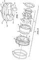
Figure 6 is an exploded view of the invention as depicted inFigures 3 and 4 . -
Figure 7 depicts an alternate embodiment of the invention. - The present invention in particular relates to permanently lubricated roller bearing mechanisms particularly for high speed turbomachines such as turbines generators or electric superchargers and will be described in that exemplary manner herein. However, the invention should not be limited to the use of the invention only for those situations and for those products. The turbomachines could support various impellers, including turbines, compressors, pumps, fans, and the like. The bearings also could be any type of standard bearings, such as ball bearings or roller bearings of various types, for example, cylindrical roller bearings, tapered roller bearings, spherical roller bearings, etc. The roller elements further could be arranged into one or more rows. The type of grease or lubrication utilized also could be any standard type, or newly compounded in the future.
- The bearings also do not have to be types which are permanently lubricated. It could be bearings which have ports for replenishment of the lubrication. The grease or lubrication preferably should be of a sufficient type and amount to seal the bearing mechanism against solid and liquid contaminants, as well as moisture. The quantity of grease applied to the bearing is typically dependent on the application. An insufficient amount of grease could lead to metal-to-metal contact and premature bearing failure. Excessive amounts of grease could cause the operating temperature within the bearing to rise too rapidly. The amount of grease also can be dependent on the speed range for the bearing. A larger quantity of lubrication (up to 100% filled) is typically utilized for low speed applications, and a smaller quantity of lubrication (e.g. 30-50%) is typically utilized for medium to high speed applications.
- Retainer members, such as end caps or end shields, also are utilized to retain the grease in the bearing and provide longer bearing life. The grease can be applied in the retainer or cap member and then the roller bearing can be assembled into or with the retainer member trapping as much of the grease as possible in the bearing-retainer assembly.
- Further, although the use of a damping or softening member, such as O-rings or metal biasing force members, is preferred, such items may not be needed with certain embodiments of the retainer and bearing assembly. A soft mounting assembly is preferred because it can reduce or prevent rotation of the retainer member, allow axial travel, assure effective axial preload, and also lower the rigid vibration modes of the rotating assembly. Soft mounting assemblies further can better accommodate thermal growth and misalignment.
- Referring to
Figure 1 , the present invention is shown being utilized in arepresentative turbine generator 10. The turbine has ahousing 15, an internally mounted rotatingshaft member 14, afluid duct 17, and animpeller 16 attached at one end of the shaft member. - The
shaft member 14 is rotatably mounted in thestator housing 12 by a pair ofbearing assemblies 18 and 20. Anelectric motor 22 in the stator housing is used to generate electric power to rotate the shaft member. The motor has astator member 24 which rotates arotor member 26 which is fixedly attached to theshaft member 14. Theturbomachine 10 also has alabyrinth seal 23, aheat shield 25, andcoolant passages 27. - The bearing
assemblies 18 and 20 can both be the same type of bearing or can be different types. The bearingassembly 20 will be described herein with respect to use of the preferred embodiment of the invention. The bearing 18 preferably is the same type and has the same components as the vented bearingassembly 20. - The
inventive bearing assembly 20 is shown inFigures 2-6 . Theassembly 20 generally includes a bearingmember 25 and aretainer member 30. In the embodiment shown, the bearing member is a roller bearing having a plurality ofspherical ball members 32 positioned in acage member 38. Although sevenball members 32 are illustrated, the number of ball members is not critical and can be any number utilized in roller bearings of this type. - The
roller bearing assembly 20 includes aninner race member 34 and anouter race member 36, both of which havecurved raceways ball holder member 36, also called a "cage," is positioned between the two race members and is used to hold the ball members in position and be spaced uniformly around the circumference of the bearing assembly. One of theball members 32 is positioned in each of theopenings 39 in thecage member 38. -
Annular shield members retainer members - The cap-
type retainer member 30 is best shown inFigures 3-6 . Theretainer member 30 has an outer (OD) circularcircumferential surface 50 and an inner (ID) circularcircumferential surface 52. Theretainer member 30 also has a radialannular flange member 54. - Preferably the
retainer member 30 is made of a metal material, with suitable strength, thermal, magnetic and manufacturing properties, such as steel or aluminum materials. Similarly, theinner race member 34 andouter race member 36 are made of similar materials. Theball members 32 are preferably made of silicon nitride or suitable materials. A metal ball material, such as steel, may have limited use for high-speed electric turbomachines due to higher centrifugal forces, thermal expansion and electric conductivity. Theholder member 38 is preferably made of a plastic or polymeric material. - A plurality of
axial vent openings 60 are provided in theretainer member 30. The vent openings are provided adjacent the innercircumferential surface 52 of theretainer member 30, as more particularly shown inFigures 5 and6 . The vent openings are provided to equalize any pressure differentials that could force lubricant past the side shields 40 and 42 and out of the bearing member. - Preferably three
vent openings 60 are provided, although the number could be less than or greater than that amount. The vent openings also are preferably uniformly spaced apart on the retainer members as shown inFigures 3-6 . Spacing the vent openings uniformly can avoid distorting the outer race. The sizes of the vents are not critical so long as appropriate pressure differentials are equalized. - A plurality of
grooves 70 are provided on the innercircumferential surface 52 of theretainer member 30. The grooves are preferably axial oriented. The depth of the grooves can be, for example, 10-80% of the thickness of the retainer member. The grooves are provided to allow any gases that may be formed in the turbine housing around the shaft member, or caused by the bearingassembly 20, to bypass and vent through thevent openings 60. Although threegrooves 70 are shown in the drawings, the actual number can be greater than three or less than three. Preferably the number is the same as the number of vent openings for efficient removal of gasses and equalization of any pressure differentials, and preferably thegrooves 70 align with, and are in communication with, thevent openings 60, as shown. - The radial bypass flow of gases from the bearing ID to the outer race of the bearing is shown by
arrow 74 inFigure 4 . Theaxial grooves 70 provide bypass flow paths on the inner circumferential surface in the manner as shown byarrow 76 inFigure 4 . - Preferably, the
vent openings 60 andgrooves 70 are formed at the same time, and with the same machining or milling procedure. The vent openings and grooves could also be made by any other conventional forming operation, such as casting, sintering, metal injection molding, 3D printing, etc. They also can be formed from one axial side of the retainer member in one step. The geometry of the vent openings and grooves as shown in the drawings provide for this to be accomplished in this manner. This reduces the cost and time needed to manufacture theretainer member 30, as well as thecomplete bearing assembly 20. - An embodiment of the invention where the
vent openings 60 andgrooves 70 can be made with a one-step machining operation is shown inFigures 5 and6 . - The vent openings through the
flange wall 54 prevent the bearing pressure differential during high speed, high boost operation. The direct bearing vents 60 also assure equalized pressure under all conditions. - In addition to the vent openings and grooves, the preferred bearing assembly also has a damping "soft" mounting feature. In one embodiment, one or more O-
ring grooves 80 are positioned on the outer (OD)circumferential surface 50 of theretainer member 30. O-ring members 82 are positioned in thegrooves 80 and extend slightly above thesurface 50, as best shown inFigure 4 . A "soft" mounting of bearingassembly 20 inturbine housing 12 is shown inFigures 1 and 2 . - When the roller bearing and retainer member assembly are installed in the housing, the O-rings provide a flexible mounting for the assembly in the turbomachine. The soft mounting provides a structural damping and lowers the speed that rigid modes of movement and vibration are encountered. The "soft" mounting also accommodates for any thermal growth and/or misalignment of the bearing assembly in the housing. The O-rings further provide friction with the housing and restrict the speed of rotation of the retainer member relative to the speed of the shaft member and roller bearing.
- The O-
rings 82 can be any conventional type of suitable chemical and temperature resistant elastomeric O-rings in use today. The O-rings positioned in the outer surface of the retainer member provide a floating mount of the bearingassembly 20 in thecompressor housing 12. - An
alternate embodiment 100 of the inventive bearing assembly is shown inFigure 7 . Thisembodiment 100 includes thesame vent openings 60 andradial grooves 70 as theembodiment 10 discussed above, but has a different damping feature. Rather than utilize one or two O-rings in circumferential grooves, theembodiment 100 instead includes a metallicstructural damper member 102 on the externalcircumferential surface 104 of the retainer member. Thedamper member 102 is preferably positioned in a circumferential groove 106 on theouter surface 104. The metallic damper member has a plurality of compliant portions ormembers 108 around its circumference that provide a biasing force on the housing. When the bearingassembly 100 is mounted or assembled in a housing, the biasingmembers 108 secure the bearing assembly in place and provide the same "soft" mounting as described above with respect toFigures 1-6 . Preferably, themetallic damper member 102 includes an anti-rotation feature, such asmembers 120, to prevent the damper member from rotating. The bearing assembly also is allowed to slide axially on the shaft member and preferably provides a radial damping force.
Claims (11)
- A bearing retainer member (30) for use with a roller bearing, said bearing retainer member (30) comprising:a circular axial extending annular wall member having an outer surface (50) and an inner surface (52), and a radially extending wall flange member (54) attached to said annular wall member,said wall flange member (54) having at least one through-opening (60) for passage of a gas therethrough, andat least one groove (70) in said inner surface (52) of said circular axial extending annular wall member.
- The bearing retainer member as set forth in claim 1 wherein a plurality of through-openings (60) are provided in said wall flange member.
- The bearing retainer member as set forth in claim 1 wherein a plurality of grooves (70) are provided in said inner surface (52) of said circular axial extending wall member.
- The bearing retainer member as described in claim 1 wherein said at least one through-opening (60) and said at least one groove (70) are substantially in axial alignment, wherein said through-opening (60) and said groove (70) can be formed in a single machining operation.
- The bearing retainer member as described in claim 1 further comprising at least one O-ring groove (80) provided circumferentially on said outer surface (50).
- A roller bearing assembly (20) comprising a roller bearing mechanism and a bearing retainer member (30) according to any one of the preceding claims, wherein said roller bearing mechanism comprises an inner race member (34), an outer race member (36) and a plurality of roller members (32) positioned between said inner and outer race members (34, 36), and wherein said roller bearing mechanism is mounted in said bearing retainer member (30), wherein pressure differentials between axial sides of said roller bearing assembly (20) can be equalized.
- The roller bearing assembly as described in claim 6, when dependent on claim 5, further comprising an O-ring (82) positioned in said O-ring groove (80).
- The roller bearing assembly as described in claim 6 further comprising a turbomachine (10) with a housing member (12), and wherein at least one roller bearing assembly (20) is positioned in said housing member (12).
- A forced induction device for an internal combustion engine, comprising:a housing (12);an impeller member (16) disposed in the housing (12);a shaft (14) to which the impeller member (16) is coupled and extending through the housing (12); anda bearing assembly (20) coupled to the shaft (14), wherein the bearing assembly (20) is coupled to the housing (12) in a radially compliant manner and balances pressure to each side of the bearing assembly (20), wherein the bearing assembly (20) includes an annular retainer (30) and a roller-element bearing received therein, the annular retainer (30) coupled to the housing (12) with an annular damping member compressed radially therebetween, and the retainer (30) includes an axially-extending passage that opens radially inward toward the roller-element bearing and balances pressure across to each side of the rolling-element bearing.
- The forced induction device of claim 9 wherein said annular damping member is either at least one O-ring member (82) or a metallic structural damper member (102).
- The forced induction device of claim 9 wherein said forced induction device is either a turbine turbomachine or a compressor turbomachine.
Applications Claiming Priority (2)
| Application Number | Priority Date | Filing Date | Title |
|---|---|---|---|
| US15/417,178 US9970450B1 (en) | 2017-01-26 | 2017-01-26 | Vented bearing retainer for turbomachines |
| PCT/US2018/015350 WO2018140665A1 (en) | 2017-01-26 | 2018-01-26 | Vented bearing retainer for turbomachines |
Publications (2)
| Publication Number | Publication Date |
|---|---|
| EP3574224A1 EP3574224A1 (en) | 2019-12-04 |
| EP3574224B1 true EP3574224B1 (en) | 2021-04-07 |
Family
ID=61193082
Family Applications (1)
| Application Number | Title | Priority Date | Filing Date |
|---|---|---|---|
| EP18704704.8A Active EP3574224B1 (en) | 2017-01-26 | 2018-01-26 | Vented bearing retainer for turbomachines |
Country Status (6)
| Country | Link |
|---|---|
| US (1) | US9970450B1 (en) |
| EP (1) | EP3574224B1 (en) |
| JP (1) | JP7217232B2 (en) |
| KR (1) | KR102556910B1 (en) |
| CN (1) | CN110402334B (en) |
| WO (1) | WO2018140665A1 (en) |
Families Citing this family (16)
| Publication number | Priority date | Publication date | Assignee | Title |
|---|---|---|---|---|
| JP6354577B2 (en) * | 2014-12-25 | 2018-07-11 | 株式会社デンソー | Valve device |
| WO2017192149A1 (en) * | 2016-05-06 | 2017-11-09 | Borgwarner Inc. | Retention component for turbomachinery device |
| DE102018115161A1 (en) * | 2018-06-25 | 2020-01-02 | Ebm-Papst St. Georgen Gmbh & Co. Kg | electric motor |
| DE102018115160A1 (en) * | 2018-06-25 | 2020-01-02 | Ebm-Papst St. Georgen Gmbh & Co. Kg | Holder for a pivot bearing |
| US11396344B2 (en) * | 2018-10-26 | 2022-07-26 | Fox Factory, Inc. | Bushing bypass |
| DE102018129612A1 (en) * | 2018-11-23 | 2020-05-28 | Ebm-Papst St. Georgen Gmbh & Co. Kg | Rotor assembly |
| JP7253936B2 (en) * | 2019-02-27 | 2023-04-07 | 三菱重工業株式会社 | Squeeze film damper bearings and rotating machinery |
| DE102019117071A1 (en) * | 2019-06-25 | 2020-12-31 | Schaeffler Technologies AG & Co. KG | Oil-cleared electric machine with roller bearings for a motor vehicle |
| JP2021055613A (en) * | 2019-09-30 | 2021-04-08 | ダイキン工業株式会社 | Turbo compressor |
| KR102261509B1 (en) | 2019-11-28 | 2021-06-07 | 주식회사 인지니어스 | Hermetic Blower for high-temperature gas |
| CN115135883A (en) * | 2020-02-20 | 2022-09-30 | 三菱重工发动机和增压器株式会社 | Compressor |
| KR102334918B1 (en) * | 2020-12-21 | 2021-12-06 | 한전케이피에스 주식회사 | Apparatus for inspection of excitor rotor shaft alignment and method thereof |
| US11624375B2 (en) | 2021-01-13 | 2023-04-11 | Garrett Transportation I Inc | Moisture removal system for electric compressor device |
| US11635093B2 (en) | 2021-01-25 | 2023-04-25 | Garrett Transportation I Inc. | Moisture evacuation system for electric compressor device |
| CN115507115A (en) * | 2021-06-07 | 2022-12-23 | 斯凯孚公司 | Rolling bearing |
| DE102024111811A1 (en) * | 2024-04-26 | 2025-10-30 | Bayerische Motoren Werke Aktiengesellschaft | Bearing seat body for a rotor shaft of an electric machine, rotor shaft, rotor, electric machine and motor vehicle |
Family Cites Families (28)
| Publication number | Priority date | Publication date | Assignee | Title |
|---|---|---|---|---|
| US3382018A (en) * | 1965-08-10 | 1968-05-07 | Ingersoll Rand Co | Liquid resistant housing vent |
| US3466478A (en) | 1967-01-09 | 1969-09-09 | Lear Siegler Inc | Bearing gas pressure equalizing structure |
| US3411707A (en) | 1967-03-23 | 1968-11-19 | Rotron Mfg Co | Apparatus for preventing gas flow through bearings |
| JPS54145851A (en) * | 1978-05-04 | 1979-11-14 | Hitachi Ltd | Device for sealing shaft |
| US4265334A (en) * | 1978-12-04 | 1981-05-05 | General Electric Company | Apparatus for lubrication of a differential bearing mounted between concentric shafts |
| DE3146137A1 (en) * | 1981-11-21 | 1983-06-01 | Skf Kugellagerfabriken Gmbh, 8720 Schweinfurt | Device for the elastic fixing of bearings |
| JPS62228693A (en) | 1986-03-31 | 1987-10-07 | Aisin Seiki Co Ltd | Poots blower |
| JP2826640B2 (en) * | 1990-02-08 | 1998-11-18 | 光洋精工株式会社 | How to fix ceramic bearings |
| US5169242A (en) * | 1990-11-27 | 1992-12-08 | General Motors Corporation | Turbocharger assembly and stabilizing journal bearing therefor |
| EP1167788A1 (en) | 2000-06-30 | 2002-01-02 | Techspace Aero S.A. | Sealing device of a squeeze film damper incorporated in a rolling element bearing |
| DE50100531D1 (en) * | 2001-07-06 | 2003-09-25 | Atlas Copco Energas | turbomachinery |
| JP2003239955A (en) | 2002-02-19 | 2003-08-27 | Yaskawa Electric Corp | Bearing support structure for rotating body |
| US7337764B2 (en) | 2003-05-30 | 2008-03-04 | Borgwarner Inc. | Pressure balanced bearing |
| ATE367678T1 (en) * | 2003-09-19 | 2007-08-15 | Dyson Technology Ltd | ROTOR ASSEMBLY |
| US6966646B1 (en) | 2004-08-10 | 2005-11-22 | Gazelle Corporation | Self-assembly glasses |
| US20070086688A1 (en) | 2005-10-17 | 2007-04-19 | Rexnord Industries, Llc | Vented bearing assembly |
| US7568843B2 (en) * | 2006-08-25 | 2009-08-04 | Pratt & Whitney Canada Corp. | Oil bearing and tube assembly concept |
| US7789567B2 (en) | 2006-08-30 | 2010-09-07 | Honeywell International Inc. | Bearing with fluid flow bypass |
| US8408806B2 (en) * | 2009-10-09 | 2013-04-02 | Dresser-Rand Company | Auxiliary bearing system with oil ring for magnetically supported rotor system |
| US7987952B2 (en) | 2009-10-28 | 2011-08-02 | GM Global Technology Operations LLC | Damping mechanisms and motor assemblies |
| JP6024233B2 (en) * | 2012-06-21 | 2016-11-09 | 株式会社Ihi | Turbine generator |
| CN202872523U (en) * | 2012-10-15 | 2013-04-10 | 台州创普机电有限公司 | Motor end cover |
| DE102012223001A1 (en) * | 2012-12-13 | 2014-06-18 | Robert Bosch Gmbh | Bearing sleeve for supporting roller bearing and arranging in housing for bearing device for turbocharger, has ring element formed as vulcanized rubber ring on bearing sleeve, where vulcanized rubber rings are arranged on bearing sleeve |
| CN203285865U (en) * | 2013-04-25 | 2013-11-13 | 常州市武进永达机械轴承有限公司 | Tapered roller bearing with end cover |
| WO2015079495A1 (en) * | 2013-11-26 | 2015-06-04 | 三菱電機株式会社 | Bearing holding structure for butterfly valve |
| JP5969571B2 (en) * | 2014-10-27 | 2016-08-17 | ファナック株式会社 | Electric motor that can prevent foreign matter from entering the housing |
| CN204493467U (en) * | 2014-12-23 | 2015-07-22 | 珠海格力节能环保制冷技术研究中心有限公司 | Bearing (ball) cover and there is its bearing support |
| CN204729480U (en) * | 2015-06-29 | 2015-10-28 | 重庆江增船舶重工有限公司 | Container-type shaft bearing structure |
-
2017
- 2017-01-26 US US15/417,178 patent/US9970450B1/en active Active
-
2018
- 2018-01-26 EP EP18704704.8A patent/EP3574224B1/en active Active
- 2018-01-26 JP JP2019540577A patent/JP7217232B2/en active Active
- 2018-01-26 WO PCT/US2018/015350 patent/WO2018140665A1/en not_active Ceased
- 2018-01-26 CN CN201880017293.0A patent/CN110402334B/en active Active
- 2018-01-26 KR KR1020197024934A patent/KR102556910B1/en active Active
Non-Patent Citations (1)
| Title |
|---|
| None * |
Also Published As
| Publication number | Publication date |
|---|---|
| JP2020507039A (en) | 2020-03-05 |
| US9970450B1 (en) | 2018-05-15 |
| CN110402334A (en) | 2019-11-01 |
| WO2018140665A1 (en) | 2018-08-02 |
| CN110402334B (en) | 2021-02-26 |
| JP7217232B2 (en) | 2023-02-02 |
| EP3574224A1 (en) | 2019-12-04 |
| KR102556910B1 (en) | 2023-07-19 |
| KR20190107127A (en) | 2019-09-18 |
Similar Documents
| Publication | Publication Date | Title |
|---|---|---|
| EP3574224B1 (en) | Vented bearing retainer for turbomachines | |
| EP2224103B1 (en) | Bearing support apparatus with squeeze film damper | |
| US5522667A (en) | Ball bearing for turbocharger | |
| US4329000A (en) | Self-contained, damped ball bearing assembly | |
| KR100715921B1 (en) | Journal bearing | |
| US7517154B2 (en) | Turbocharger shaft bearing system | |
| US7371011B2 (en) | Turbocharger shaft bearing system | |
| CN110005545B (en) | Squirrel-cage elastic supporting bearing cavity structure | |
| US9874217B2 (en) | Turbomachine shaft sealing arrangement | |
| EP2042758A2 (en) | Rolling bearing device and turbocharger incorporating same | |
| US9803493B2 (en) | Turbine bearing and seal assembly for a turbocharger | |
| EP2078825A2 (en) | Turbocharger | |
| US20080087018A1 (en) | Bearing systems for high-speed rotating machinery | |
| EP2977562A1 (en) | Bearing compartment sealing system | |
| JP2002369474A (en) | Rolling bearing device for impeller shaft support | |
| US4116502A (en) | Dual bearing structure for rotatable machine parts with antifriction and plain bearings | |
| JP2003329045A (en) | Rolling bearing for hybrid vehicle drive motor and hybrid vehicle drive motor | |
| US4451048A (en) | High speed shaft seal | |
| US11143046B2 (en) | Seal runner and method | |
| US10260563B2 (en) | Bearing cages for roller bearing assemblies | |
| JP2005147029A (en) | Turbocharger | |
| JP6540281B2 (en) | Double row ball bearing | |
| JP2020041585A (en) | Rolling bearing | |
| GB2286860A (en) | Ball bearing for turbocharger |
Legal Events
| Date | Code | Title | Description |
|---|---|---|---|
| STAA | Information on the status of an ep patent application or granted ep patent |
Free format text: STATUS: UNKNOWN |
|
| STAA | Information on the status of an ep patent application or granted ep patent |
Free format text: STATUS: THE INTERNATIONAL PUBLICATION HAS BEEN MADE |
|
| PUAI | Public reference made under article 153(3) epc to a published international application that has entered the european phase |
Free format text: ORIGINAL CODE: 0009012 |
|
| STAA | Information on the status of an ep patent application or granted ep patent |
Free format text: STATUS: REQUEST FOR EXAMINATION WAS MADE |
|
| 17P | Request for examination filed |
Effective date: 20190826 |
|
| AK | Designated contracting states |
Kind code of ref document: A1 Designated state(s): AL AT BE BG CH CY CZ DE DK EE ES FI FR GB GR HR HU IE IS IT LI LT LU LV MC MK MT NL NO PL PT RO RS SE SI SK SM TR |
|
| AX | Request for extension of the european patent |
Extension state: BA ME |
|
| DAV | Request for validation of the european patent (deleted) | ||
| DAX | Request for extension of the european patent (deleted) | ||
| GRAP | Despatch of communication of intention to grant a patent |
Free format text: ORIGINAL CODE: EPIDOSNIGR1 |
|
| STAA | Information on the status of an ep patent application or granted ep patent |
Free format text: STATUS: GRANT OF PATENT IS INTENDED |
|
| INTG | Intention to grant announced |
Effective date: 20201030 |
|
| GRAS | Grant fee paid |
Free format text: ORIGINAL CODE: EPIDOSNIGR3 |
|
| GRAA | (expected) grant |
Free format text: ORIGINAL CODE: 0009210 |
|
| STAA | Information on the status of an ep patent application or granted ep patent |
Free format text: STATUS: THE PATENT HAS BEEN GRANTED |
|
| AK | Designated contracting states |
Kind code of ref document: B1 Designated state(s): AL AT BE BG CH CY CZ DE DK EE ES FI FR GB GR HR HU IE IS IT LI LT LU LV MC MK MT NL NO PL PT RO RS SE SI SK SM TR |
|
| REG | Reference to a national code |
Ref country code: GB Ref legal event code: FG4D |
|
| REG | Reference to a national code |
Ref country code: AT Ref legal event code: REF Ref document number: 1380055 Country of ref document: AT Kind code of ref document: T Effective date: 20210415 Ref country code: CH Ref legal event code: EP |
|
| REG | Reference to a national code |
Ref country code: DE Ref legal event code: R096 Ref document number: 602018015156 Country of ref document: DE |
|
| REG | Reference to a national code |
Ref country code: IE Ref legal event code: FG4D |
|
| REG | Reference to a national code |
Ref country code: LT Ref legal event code: MG9D |
|
| REG | Reference to a national code |
Ref country code: NL Ref legal event code: MP Effective date: 20210407 Ref country code: AT Ref legal event code: MK05 Ref document number: 1380055 Country of ref document: AT Kind code of ref document: T Effective date: 20210407 |
|
| PG25 | Lapsed in a contracting state [announced via postgrant information from national office to epo] |
Ref country code: BG Free format text: LAPSE BECAUSE OF FAILURE TO SUBMIT A TRANSLATION OF THE DESCRIPTION OR TO PAY THE FEE WITHIN THE PRESCRIBED TIME-LIMIT Effective date: 20210707 Ref country code: AT Free format text: LAPSE BECAUSE OF FAILURE TO SUBMIT A TRANSLATION OF THE DESCRIPTION OR TO PAY THE FEE WITHIN THE PRESCRIBED TIME-LIMIT Effective date: 20210407 Ref country code: NL Free format text: LAPSE BECAUSE OF FAILURE TO SUBMIT A TRANSLATION OF THE DESCRIPTION OR TO PAY THE FEE WITHIN THE PRESCRIBED TIME-LIMIT Effective date: 20210407 Ref country code: FI Free format text: LAPSE BECAUSE OF FAILURE TO SUBMIT A TRANSLATION OF THE DESCRIPTION OR TO PAY THE FEE WITHIN THE PRESCRIBED TIME-LIMIT Effective date: 20210407 Ref country code: HR Free format text: LAPSE BECAUSE OF FAILURE TO SUBMIT A TRANSLATION OF THE DESCRIPTION OR TO PAY THE FEE WITHIN THE PRESCRIBED TIME-LIMIT Effective date: 20210407 Ref country code: LT Free format text: LAPSE BECAUSE OF FAILURE TO SUBMIT A TRANSLATION OF THE DESCRIPTION OR TO PAY THE FEE WITHIN THE PRESCRIBED TIME-LIMIT Effective date: 20210407 |
|
| PG25 | Lapsed in a contracting state [announced via postgrant information from national office to epo] |
Ref country code: GR Free format text: LAPSE BECAUSE OF FAILURE TO SUBMIT A TRANSLATION OF THE DESCRIPTION OR TO PAY THE FEE WITHIN THE PRESCRIBED TIME-LIMIT Effective date: 20210708 Ref country code: IS Free format text: LAPSE BECAUSE OF FAILURE TO SUBMIT A TRANSLATION OF THE DESCRIPTION OR TO PAY THE FEE WITHIN THE PRESCRIBED TIME-LIMIT Effective date: 20210807 Ref country code: LV Free format text: LAPSE BECAUSE OF FAILURE TO SUBMIT A TRANSLATION OF THE DESCRIPTION OR TO PAY THE FEE WITHIN THE PRESCRIBED TIME-LIMIT Effective date: 20210407 Ref country code: PT Free format text: LAPSE BECAUSE OF FAILURE TO SUBMIT A TRANSLATION OF THE DESCRIPTION OR TO PAY THE FEE WITHIN THE PRESCRIBED TIME-LIMIT Effective date: 20210809 Ref country code: NO Free format text: LAPSE BECAUSE OF FAILURE TO SUBMIT A TRANSLATION OF THE DESCRIPTION OR TO PAY THE FEE WITHIN THE PRESCRIBED TIME-LIMIT Effective date: 20210707 Ref country code: PL Free format text: LAPSE BECAUSE OF FAILURE TO SUBMIT A TRANSLATION OF THE DESCRIPTION OR TO PAY THE FEE WITHIN THE PRESCRIBED TIME-LIMIT Effective date: 20210407 Ref country code: RS Free format text: LAPSE BECAUSE OF FAILURE TO SUBMIT A TRANSLATION OF THE DESCRIPTION OR TO PAY THE FEE WITHIN THE PRESCRIBED TIME-LIMIT Effective date: 20210407 Ref country code: SE Free format text: LAPSE BECAUSE OF FAILURE TO SUBMIT A TRANSLATION OF THE DESCRIPTION OR TO PAY THE FEE WITHIN THE PRESCRIBED TIME-LIMIT Effective date: 20210407 |
|
| REG | Reference to a national code |
Ref country code: DE Ref legal event code: R097 Ref document number: 602018015156 Country of ref document: DE |
|
| PG25 | Lapsed in a contracting state [announced via postgrant information from national office to epo] |
Ref country code: SK Free format text: LAPSE BECAUSE OF FAILURE TO SUBMIT A TRANSLATION OF THE DESCRIPTION OR TO PAY THE FEE WITHIN THE PRESCRIBED TIME-LIMIT Effective date: 20210407 Ref country code: SM Free format text: LAPSE BECAUSE OF FAILURE TO SUBMIT A TRANSLATION OF THE DESCRIPTION OR TO PAY THE FEE WITHIN THE PRESCRIBED TIME-LIMIT Effective date: 20210407 Ref country code: EE Free format text: LAPSE BECAUSE OF FAILURE TO SUBMIT A TRANSLATION OF THE DESCRIPTION OR TO PAY THE FEE WITHIN THE PRESCRIBED TIME-LIMIT Effective date: 20210407 Ref country code: ES Free format text: LAPSE BECAUSE OF FAILURE TO SUBMIT A TRANSLATION OF THE DESCRIPTION OR TO PAY THE FEE WITHIN THE PRESCRIBED TIME-LIMIT Effective date: 20210407 Ref country code: RO Free format text: LAPSE BECAUSE OF FAILURE TO SUBMIT A TRANSLATION OF THE DESCRIPTION OR TO PAY THE FEE WITHIN THE PRESCRIBED TIME-LIMIT Effective date: 20210407 Ref country code: CZ Free format text: LAPSE BECAUSE OF FAILURE TO SUBMIT A TRANSLATION OF THE DESCRIPTION OR TO PAY THE FEE WITHIN THE PRESCRIBED TIME-LIMIT Effective date: 20210407 Ref country code: DK Free format text: LAPSE BECAUSE OF FAILURE TO SUBMIT A TRANSLATION OF THE DESCRIPTION OR TO PAY THE FEE WITHIN THE PRESCRIBED TIME-LIMIT Effective date: 20210407 |
|
| PLBE | No opposition filed within time limit |
Free format text: ORIGINAL CODE: 0009261 |
|
| STAA | Information on the status of an ep patent application or granted ep patent |
Free format text: STATUS: NO OPPOSITION FILED WITHIN TIME LIMIT |
|
| 26N | No opposition filed |
Effective date: 20220110 |
|
| PG25 | Lapsed in a contracting state [announced via postgrant information from national office to epo] |
Ref country code: IS Free format text: LAPSE BECAUSE OF FAILURE TO SUBMIT A TRANSLATION OF THE DESCRIPTION OR TO PAY THE FEE WITHIN THE PRESCRIBED TIME-LIMIT Effective date: 20210807 Ref country code: AL Free format text: LAPSE BECAUSE OF FAILURE TO SUBMIT A TRANSLATION OF THE DESCRIPTION OR TO PAY THE FEE WITHIN THE PRESCRIBED TIME-LIMIT Effective date: 20210407 |
|
| PG25 | Lapsed in a contracting state [announced via postgrant information from national office to epo] |
Ref country code: IT Free format text: LAPSE BECAUSE OF FAILURE TO SUBMIT A TRANSLATION OF THE DESCRIPTION OR TO PAY THE FEE WITHIN THE PRESCRIBED TIME-LIMIT Effective date: 20210407 |
|
| PG25 | Lapsed in a contracting state [announced via postgrant information from national office to epo] |
Ref country code: MC Free format text: LAPSE BECAUSE OF FAILURE TO SUBMIT A TRANSLATION OF THE DESCRIPTION OR TO PAY THE FEE WITHIN THE PRESCRIBED TIME-LIMIT Effective date: 20210407 |
|
| REG | Reference to a national code |
Ref country code: CH Ref legal event code: PL |
|
| GBPC | Gb: european patent ceased through non-payment of renewal fee |
Effective date: 20220126 |
|
| REG | Reference to a national code |
Ref country code: BE Ref legal event code: MM Effective date: 20220131 |
|
| PG25 | Lapsed in a contracting state [announced via postgrant information from national office to epo] |
Ref country code: LU Free format text: LAPSE BECAUSE OF NON-PAYMENT OF DUE FEES Effective date: 20220126 Ref country code: GB Free format text: LAPSE BECAUSE OF NON-PAYMENT OF DUE FEES Effective date: 20220126 |
|
| PG25 | Lapsed in a contracting state [announced via postgrant information from national office to epo] |
Ref country code: FR Free format text: LAPSE BECAUSE OF NON-PAYMENT OF DUE FEES Effective date: 20220131 Ref country code: BE Free format text: LAPSE BECAUSE OF NON-PAYMENT OF DUE FEES Effective date: 20220131 |
|
| PG25 | Lapsed in a contracting state [announced via postgrant information from national office to epo] |
Ref country code: LI Free format text: LAPSE BECAUSE OF NON-PAYMENT OF DUE FEES Effective date: 20220131 Ref country code: CH Free format text: LAPSE BECAUSE OF NON-PAYMENT OF DUE FEES Effective date: 20220131 |
|
| PG25 | Lapsed in a contracting state [announced via postgrant information from national office to epo] |
Ref country code: IE Free format text: LAPSE BECAUSE OF NON-PAYMENT OF DUE FEES Effective date: 20220126 |
|
| P01 | Opt-out of the competence of the unified patent court (upc) registered |
Effective date: 20230327 |
|
| PG25 | Lapsed in a contracting state [announced via postgrant information from national office to epo] |
Ref country code: MK Free format text: LAPSE BECAUSE OF FAILURE TO SUBMIT A TRANSLATION OF THE DESCRIPTION OR TO PAY THE FEE WITHIN THE PRESCRIBED TIME-LIMIT Effective date: 20210407 Ref country code: CY Free format text: LAPSE BECAUSE OF FAILURE TO SUBMIT A TRANSLATION OF THE DESCRIPTION OR TO PAY THE FEE WITHIN THE PRESCRIBED TIME-LIMIT Effective date: 20210407 |
|
| PG25 | Lapsed in a contracting state [announced via postgrant information from national office to epo] |
Ref country code: HU Free format text: LAPSE BECAUSE OF FAILURE TO SUBMIT A TRANSLATION OF THE DESCRIPTION OR TO PAY THE FEE WITHIN THE PRESCRIBED TIME-LIMIT; INVALID AB INITIO Effective date: 20180126 |
|
| PG25 | Lapsed in a contracting state [announced via postgrant information from national office to epo] |
Ref country code: MT Free format text: LAPSE BECAUSE OF FAILURE TO SUBMIT A TRANSLATION OF THE DESCRIPTION OR TO PAY THE FEE WITHIN THE PRESCRIBED TIME-LIMIT Effective date: 20210407 |
|
| PG25 | Lapsed in a contracting state [announced via postgrant information from national office to epo] |
Ref country code: TR Free format text: LAPSE BECAUSE OF FAILURE TO SUBMIT A TRANSLATION OF THE DESCRIPTION OR TO PAY THE FEE WITHIN THE PRESCRIBED TIME-LIMIT Effective date: 20210407 |
|
| PGFP | Annual fee paid to national office [announced via postgrant information from national office to epo] |
Ref country code: DE Payment date: 20251222 Year of fee payment: 9 |