EP3574205B1 - Control valve assembly and method of manufacturing thereof - Google Patents
Control valve assembly and method of manufacturing thereof Download PDFInfo
- Publication number
- EP3574205B1 EP3574205B1 EP18702476.5A EP18702476A EP3574205B1 EP 3574205 B1 EP3574205 B1 EP 3574205B1 EP 18702476 A EP18702476 A EP 18702476A EP 3574205 B1 EP3574205 B1 EP 3574205B1
- Authority
- EP
- European Patent Office
- Prior art keywords
- face
- valve
- spool
- sleeve
- bore
- Prior art date
- Legal status (The legal status is an assumption and is not a legal conclusion. Google has not performed a legal analysis and makes no representation as to the accuracy of the status listed.)
- Active
Links
Images
Classifications
-
- F—MECHANICAL ENGINEERING; LIGHTING; HEATING; WEAPONS; BLASTING
- F02—COMBUSTION ENGINES; HOT-GAS OR COMBUSTION-PRODUCT ENGINE PLANTS
- F02M—SUPPLYING COMBUSTION ENGINES IN GENERAL WITH COMBUSTIBLE MIXTURES OR CONSTITUENTS THEREOF
- F02M63/00—Other fuel-injection apparatus having pertinent characteristics not provided for in groups F02M39/00 - F02M57/00 or F02M67/00; Details, component parts, or accessories of fuel-injection apparatus, not provided for in, or of interest apart from, the apparatus of groups F02M39/00 - F02M61/00 or F02M67/00; Combination of fuel pump with other devices, e.g. lubricating oil pump
- F02M63/0012—Valves
- F02M63/0031—Valves characterized by the type of valves, e.g. special valve member details, valve seat details, valve housing details
- F02M63/004—Sliding valves, e.g. spool valves, i.e. whereby the closing member has a sliding movement along a seat for opening and closing
-
- F—MECHANICAL ENGINEERING; LIGHTING; HEATING; WEAPONS; BLASTING
- F02—COMBUSTION ENGINES; HOT-GAS OR COMBUSTION-PRODUCT ENGINE PLANTS
- F02M—SUPPLYING COMBUSTION ENGINES IN GENERAL WITH COMBUSTIBLE MIXTURES OR CONSTITUENTS THEREOF
- F02M63/00—Other fuel-injection apparatus having pertinent characteristics not provided for in groups F02M39/00 - F02M57/00 or F02M67/00; Details, component parts, or accessories of fuel-injection apparatus, not provided for in, or of interest apart from, the apparatus of groups F02M39/00 - F02M61/00 or F02M67/00; Combination of fuel pump with other devices, e.g. lubricating oil pump
- F02M63/0012—Valves
- F02M63/0059—Arrangements of valve actuators
- F02M63/0064—Two or more actuators acting on two or more valve bodies
-
- B—PERFORMING OPERATIONS; TRANSPORTING
- B23—MACHINE TOOLS; METAL-WORKING NOT OTHERWISE PROVIDED FOR
- B23P—METAL-WORKING NOT OTHERWISE PROVIDED FOR; COMBINED OPERATIONS; UNIVERSAL MACHINE TOOLS
- B23P15/00—Making specific metal objects by operations not covered by a single other subclass or a group in this subclass
- B23P15/001—Making specific metal objects by operations not covered by a single other subclass or a group in this subclass valves or valve housings
-
- F—MECHANICAL ENGINEERING; LIGHTING; HEATING; WEAPONS; BLASTING
- F02—COMBUSTION ENGINES; HOT-GAS OR COMBUSTION-PRODUCT ENGINE PLANTS
- F02M—SUPPLYING COMBUSTION ENGINES IN GENERAL WITH COMBUSTIBLE MIXTURES OR CONSTITUENTS THEREOF
- F02M47/00—Fuel-injection apparatus operated cyclically with fuel-injection valves actuated by fluid pressure
- F02M47/02—Fuel-injection apparatus operated cyclically with fuel-injection valves actuated by fluid pressure of accumulator-injector type, i.e. having fuel pressure of accumulator tending to open, and fuel pressure in other chamber tending to close, injection valves and having means for periodically releasing that closing pressure
- F02M47/027—Electrically actuated valves draining the chamber to release the closing pressure
-
- F—MECHANICAL ENGINEERING; LIGHTING; HEATING; WEAPONS; BLASTING
- F02—COMBUSTION ENGINES; HOT-GAS OR COMBUSTION-PRODUCT ENGINE PLANTS
- F02M—SUPPLYING COMBUSTION ENGINES IN GENERAL WITH COMBUSTIBLE MIXTURES OR CONSTITUENTS THEREOF
- F02M51/00—Fuel-injection apparatus characterised by being operated electrically
- F02M51/06—Injectors peculiar thereto with means directly operating the valve needle
- F02M51/061—Injectors peculiar thereto with means directly operating the valve needle using electromagnetic operating means
- F02M51/0625—Injectors peculiar thereto with means directly operating the valve needle using electromagnetic operating means characterised by arrangement of mobile armatures
-
- F—MECHANICAL ENGINEERING; LIGHTING; HEATING; WEAPONS; BLASTING
- F02—COMBUSTION ENGINES; HOT-GAS OR COMBUSTION-PRODUCT ENGINE PLANTS
- F02M—SUPPLYING COMBUSTION ENGINES IN GENERAL WITH COMBUSTIBLE MIXTURES OR CONSTITUENTS THEREOF
- F02M63/00—Other fuel-injection apparatus having pertinent characteristics not provided for in groups F02M39/00 - F02M57/00 or F02M67/00; Details, component parts, or accessories of fuel-injection apparatus, not provided for in, or of interest apart from, the apparatus of groups F02M39/00 - F02M61/00 or F02M67/00; Combination of fuel pump with other devices, e.g. lubricating oil pump
- F02M63/0012—Valves
- F02M63/0031—Valves characterized by the type of valves, e.g. special valve member details, valve seat details, valve housing details
- F02M63/0033—Lift valves, i.e. having a valve member that moves perpendicularly to the plane of the valve seat
- F02M63/0035—Poppet valves, i.e. having a mushroom-shaped valve member that moves perpendicularly to the plane of the valve seat
-
- F—MECHANICAL ENGINEERING; LIGHTING; HEATING; WEAPONS; BLASTING
- F02—COMBUSTION ENGINES; HOT-GAS OR COMBUSTION-PRODUCT ENGINE PLANTS
- F02M—SUPPLYING COMBUSTION ENGINES IN GENERAL WITH COMBUSTIBLE MIXTURES OR CONSTITUENTS THEREOF
- F02M2200/00—Details of fuel-injection apparatus, not otherwise provided for
- F02M2200/46—Valves, e.g. injectors, with concentric valve bodies
-
- F—MECHANICAL ENGINEERING; LIGHTING; HEATING; WEAPONS; BLASTING
- F02—COMBUSTION ENGINES; HOT-GAS OR COMBUSTION-PRODUCT ENGINE PLANTS
- F02M—SUPPLYING COMBUSTION ENGINES IN GENERAL WITH COMBUSTIBLE MIXTURES OR CONSTITUENTS THEREOF
- F02M2200/00—Details of fuel-injection apparatus, not otherwise provided for
- F02M2200/80—Fuel injection apparatus manufacture, repair or assembly
- F02M2200/8061—Fuel injection apparatus manufacture, repair or assembly involving press-fit, i.e. interference or friction fit
-
- F—MECHANICAL ENGINEERING; LIGHTING; HEATING; WEAPONS; BLASTING
- F02—COMBUSTION ENGINES; HOT-GAS OR COMBUSTION-PRODUCT ENGINE PLANTS
- F02M—SUPPLYING COMBUSTION ENGINES IN GENERAL WITH COMBUSTIBLE MIXTURES OR CONSTITUENTS THEREOF
- F02M2200/00—Details of fuel-injection apparatus, not otherwise provided for
- F02M2200/80—Fuel injection apparatus manufacture, repair or assembly
- F02M2200/8069—Fuel injection apparatus manufacture, repair or assembly involving removal of material from the fuel apparatus, e.g. by punching, hydro-erosion or mechanical operation
-
- F—MECHANICAL ENGINEERING; LIGHTING; HEATING; WEAPONS; BLASTING
- F02—COMBUSTION ENGINES; HOT-GAS OR COMBUSTION-PRODUCT ENGINE PLANTS
- F02M—SUPPLYING COMBUSTION ENGINES IN GENERAL WITH COMBUSTIBLE MIXTURES OR CONSTITUENTS THEREOF
- F02M2200/00—Details of fuel-injection apparatus, not otherwise provided for
- F02M2200/80—Fuel injection apparatus manufacture, repair or assembly
- F02M2200/8092—Fuel injection apparatus manufacture, repair or assembly adjusting or calibration
Definitions
- the present invention relates to a control valve assembly of a fuel injector and to the manufacturing of a precision valve lift.
- Fuel injectors comprise a control valve assembly for varying the pressure in a control chamber and commanding the moves of a needle valve member enabling or preventing injection events.
- a valve spool slides within a bore of a valve body to alternatively open and close a spill orifice.
- the maximum valve lift which is to be adjusted within a dimensional tolerance of few micrometers, is set by taking measurements of the spool head height and, adjusting the valve lift to the desired value by adding shim of appropriate thickness.
- Another effective way of achieving an accurate lift is to use selective assembly methods wherein the components are manufactured and sorted in families prior to be paired with other components to form valve assemblies. Although being efficient, such a process is not desired for the valve arrangement and production environment, the problem being to ensure that the correct distribution of parts is manufactured to cover the variability of the combinations of components. A large selection of parts may remain unused or, issues may arise where the right distribution of parts is not available to achieve the correct combination.
- Some injectors are designed with two valve arrangements, each comprising a spool sliding in a bore between closed and open positions.
- the problem of having the correct valve lift for both is amplified with such control valve assemblies. Due to process variability it is unlikely that all valve heads will be the same, so to achieve equal lifts is a major problem however the challenge remains the same where different lifts are required for each valve.
- US2005098144A1 discloses a fuel injector with a homogenous charge nozzle outlet set and a conventional nozzle outlet set that are controlled respectively by first and second three-way needle control valves.
- Each fuel injector includes first and second concentric needle valve members. One of the needle valve members moves to an open position for a homogenous charge injection event, while the other needle valve member moves to an open position for a conventional injection event.
- the fuel injector has the ability to operate in a homogenous charge mode with a homogenous charge spray pattern, a conventional mode with a conventional spray pattern or a mixed mode.
- EP 1 612 398 A1 shows a control servo valve housed inside the casing of an internal combustion engine fuel injector, the outlet passage comes out inside an annular chamber defined by a fixed tubular portion and by a shutter, which engages the tubular portion in substantially fluid tight manner.
- valve assembly comprising a first valve arrangement wherein a first valve spool is guided in a first hydraulic bore provided in a body (18) of the assembly, said spool being adapted to move between a closed position wherein a shoulder face of a head member of said first spool is in sealing contact against a first seating face and, a fully open position wherein a distant end face of said head member is in flush continuity with an under face of the body of the valve assembly, the shoulder face of the first spool being lifted away from said first seating face.
- control valve assembly further comprises a first tubular sleeve having a seating portion which end face defines said first seating face, the first sleeve being fixed in the first hydraulic bore and the first spool extending through said sleeve.
- the first sleeve further comprises a spool guiding portion integral to the press-fitted seating portion, said guiding portion being arranged inside the hydraulic bore.
- said spool guiding portion has an inner guiding face against which, in use, slides the spool and, externally an outer face distant from the bore by an outer annular clearance.
- the seating portion is press-fitted in the bore and, it has an inner face defining an inner clearance with the spool.
- the control valve further comprises a second valve arrangement, similar to the first valve arrangement, wherein a second spool is guided in a second hydraulic bore provided in the body of the assembly, said second spool being adapted to move between a closed position wherein a shoulder face of a head member of said second spool is in sealing contact against a second seating face and, a fully open position wherein a distant end face of said second head member is in flush continuity with an under face of the body of the valve assembly, the shoulder face of the second spool being lifted from said second seating face.
- a second valve arrangement similar to the first valve arrangement, wherein a second spool is guided in a second hydraulic bore provided in the body of the assembly, said second spool being adapted to move between a closed position wherein a shoulder face of a head member of said second spool is in sealing contact against a second seating face and, a fully open position wherein a distant end face of said second head member is in flush continuity with an under face of the body of the valve assembly, the shoulder face
- the control valve assembly further comprises a second tubular sleeve having a second seating portion defining said second seating face, said second sleeve being fixed in the second hydraulic bore, the second spool extending through said second sleeve.
- the second sleeve has an outer face press fitted in the second bore (34) and, an inner face defining a second clearance with the second spool.
- the body of the valve assembly comprises a valve guide member provided with the hydraulic bore and, a valve plate having an upper face and an opposed under face, the upper face being arranged in surface abutment against an under face of the valve guide member, said valve plate being further provided with a through opening aligned with the hydraulic bore, the sleeve being fixed in the valve guide member so that the seating face lies parallel and in close vicinity to the under face of the valve guide member, either slightly recessed inside the hydraulic bore or slightly protruding in the opening.
- the second hydraulic bore is defined in the valve guide member and, the valve plate is provided with a second through opening aligned with the second hydraulic bore, the second sleeve being press fitted in the valve guide member so that the second seating face lies parallel and in close vicinity to the under face of the valve guide member, either slightly recessed inside the second hydraulic bore or slightly protruding in the second opening.
- the invention further extends to a fuel injector comprising a control valve assembly as previously described.
- the invention further extends to a method of manufacturing a control valve assembly as previously described, the method particularly enabling to ensure a precised valve lift measured between the closed position and the fully open position of the valve arrangement, the method comprising the steps of:
- the providing step is:
- the method further comprises the step:
- the adjusting step comprises:
- a fuel injector 10 To inject fuel in a cylinder of an internal combustion engine, a fuel injector 10 is provided with a control valve assembly 12 arranged between an actuator member and a nozzle assembly, all said parts being firmly maintained together by a capnut.
- the control valve assembly 12 enables to vary the pressure in a control chamber such that, a needle valve sliding in the nozzle moves to open or to close spray holes and thus enables or forbids injection events.
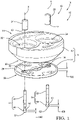
- control valve assembly 12 shown on figure 1 is taken from a diesel fuel injector 10 and, it comprises a first 14 and a second 16 valve arrangement cooperating together for enabling pressurised fuel to enter the control chamber and then, for preventing said entry when the fuel therein is expelled toward a low pressure tank.
- the first 14 and second 16 valve arrangements are similar, each comprising a hydraulic bore 32, 34 defining a seating face 40, 42 cooperating with a shoulder face 50, 60 defined on a valve spool 44, 54 slidably arranged in the bore.
- the spool comprises a thin and elongated core 46, 56 enlarging at an end to form a larger valve head 48, 58 defining said seat face.
- control valve assembly 12 has a body 18 comprising a valve guide member 20, a valve plate 22, a first sleeve 24 and a second sleeve 26.
- the valve plate 22 is arranged beneath the guide member 20, the upper face 28 of the plate 22 being in surface contact against the under face 30 of the guide member 20, said valve plate 22 having a thickness T22 measured between said upper face 28 and an opposed under face 29.
- valve body 18 may be monobloc, integrating in one piece the valve guide 20 and the valve plate 22, the under face 29 being in such alternative the under face of the body 18.
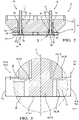
- the first valve arrangement 14 comprises a first hydraulic bore 32 and, the second valve arrangement 16 comprises a second hydraulic bore 34, both bores 32, 34 being parallel to each other and extending along a main axis X to which the under face 30 of the valve guide and the upper face 28 of the valve plate are perpendicular.
- the two bores 32, 34 are provided in the guide member 20 and are both opening in said under face 30.
- the valve plate 22 is complementary provided with a first opening 36 aligned with the first bore 32 and, with a second opening 38 aligned with the second bore 34.
- each of the bores 32, 34 open in large recesses forming chambers adapted to house magnetic armatures, not shown, cooperating with a solenoid of the actuator member.
- the first sleeve 24 is inserted with press-fit in the first bore 32 and similarly, the second sleeve 26 is inserted with press-fit in the second bore 34, each of the first 24 and the second 26 sleeve being a cylindrical tubular member arranged so their lower end face, respectively defining a first valve seating face 40 and a second valve seating face 42, is flush with the under face 30 of the guide member.
- the actual first distance D40 from said first valve seating face 40 to the under face 30 and, the actual second distance D42 from said second valve seating face 42 to the under face 30 are within a range of few micrometers, said distances D40, D42 being counted positive when the sleeve is slightly recessed inside the bore and negative when the sleeve protrudes outside.
- the first valve arrangement 14 further comprises a first valve spool 44 guided in the first bore 32 and similarly, the second valve arrangement 16 further comprises with a second valve spool 54 guided in the second bore 34.
- the first valve spool 44 has a thin and elongated core 46 enlarging at an end into a larger head member 48, a shoulder face 50 joining the core 46 to the head member 48 and defining said first seat face.
- the core 46 is guided in the first bore 32 and it extends through the first sleeve 24 while the head member 48 protrudes outside of the first bore 32 and of the sleeve 24, inside the first opening 36 of the valve plate.
- the head member 48 has a height H48 axially X extending from said shoulder face 50 to a distant transverse end face 52, said height H48 being smaller than the thickness T22 of the valve plate 22.
- the first spool 44 Opposite to the head 48, the first spool 44 upwardly extends in the large recess and a first magnetic armature, not shown, is fixed to said part of the spool.
- the injector 10 is assembled so, an upper face of the nozzle assembly is pressed in surface contact against the under face 29 of the valve plate closing, at least partially, the first and second openings 36, 38 of the valve plate.
- the shoulder face 50 of the first spool 44 cooperates with the first seating face 40 of the first sleeve as said first spool 44 axially slides between an open position OP and a closed position CP.
- open position OP the shoulder face 50 is lifted away from the first seating face 40 and the end face 52 of the head abuts said upper face of the nozzle so, said end face 52 lies in exact flush continuity with the under face 29 of the valve plate.
- closed position CP the shoulder face 50 is in sealing contact against the first valve seating face 40 and, the end face 52 of the head is recessed inside the first opening 36 away from the upper face of the nozzle.
- the second valve spool 54 has an elongated thin core 56 enlarging at an end into a larger head member 58, a shoulder face 60 joining the core 56 to the head member 58 and defining said second seat face.
- the core 56 is guided in the second bore 34 and it extends through the second sleeve 26 while the head member 58 protrudes outside of the second bore 34 and of the second sleeve 26, inside the second opening 38 of the valve plate.
- the head member 58 has a height H58 axially X extending from said shoulder face 60 to a distant transverse end face 62, said height H58 being smaller than the thickness T22 of the valve plate 22.
- the second spool 54 Opposite to the head 58, the second spool 54 upwardly extends in the large recess and a second magnetic armature, not shown, is fixed to said part of the spool.
- the operation of the second valve arrangement 16 requires the shoulder face 60 of the second spool 54 and the second seating face 42 of the second sleeve to cooperate together as said second spool 54 axially slides in the body 18 between an open position OP and a closed position CP.
- said open position OP the shoulder face 60 is lifted away from the second seating face 42 and the end face 62 of the head abuts the upper face of the nozzle so, said end face 62 lies in exact flush continuity with the under face 29 of the valve plate.
- closed position CP the shoulder face 60 is in sealing contact against the second valve seating face 42 and the end face 62 of the head is recessed inside the second opening 38 away from the upper face of the nozzle.
- said distances D40, D42 are counted positive when the sleeve is slightly recessed inside the bore because increasing the available lift distance and, being counted negative when the sleeve protrudes outside the bore thus decreasing the available distance.
- the respective height H48, H58 of the first 48 and second 58 head members differ within a dimensional tolerance of few microns.
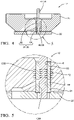
- the first sleeve 24 integrally comprises a seating portion 64 and a guiding portion 66, the seating portion 64, drawn at the bottom of the figure, defining the seating face 40 and, the guiding portion 66, drawn above, entirely lying inside the first hydraulic bore 32.
- Said first sleeve 24 defines an inner clearance C64 between the first spool 44 and the inner face 68 of said seating portion 64 and, an outer annular clearance C66 between the outer face of the guiding portion 66 and the first bore 32.
- the first spool 44 being axially guided by the inner face 70 of the guiding portion 66. Thanks to this sleeve arrangement, dilation of the stem bore 70 is prevented since equal pressure is acting on both sides of the sleeve guiding portion 66, then dilation of the bore is minimised as the net radial force is balanced.
- the lift of the spool is individually tuned in following the steps of a method 100, which in a first stage is detailed considering a control valve assembly 12 having an integral mono-bloc body and a single valve arrangement.
- the steps of said method 100 are as follow:
- the method 100 further comprises: 124) surfacing together the valve guide under face 30 and the sleeve 24 so that the bottom end of said sleeve defining the seating face 40 is exactly flush in surface continuity with the valve guide under face 30.
- Said surfacing 124 can for instance be a grinding operation.
- the thickness T22 of the valve plate corresponds to the depth of the larger recess in which opens the bore.
- the spool is chosen so the height H48 of its ahead is smaller than the thickness T22 of the plate or the depth of the recess.
- Said fine positioning step 144 may consist in pushing the sleeves outwardly so it protrudes by said distance D40, D42 outside the bore or, in pushing inwardly should the seating face be recessed relative the guide under face. It could finally consist not moving a sleeve at all, should the initial position be correct.
- the lifts L44, L54 being independently tuned, may be selected to differ from each other, one sleeve being pushed inwardly while the other is pushed outwardly.
- a control valve assembly provided with more than two valve arrangements can similarly benefit for the invention by having, in each valve arrangement a sleeve which position is individually adjusted.
Landscapes
- Engineering & Computer Science (AREA)
- Mechanical Engineering (AREA)
- Chemical & Material Sciences (AREA)
- Combustion & Propulsion (AREA)
- General Engineering & Computer Science (AREA)
- Physics & Mathematics (AREA)
- Fluid Mechanics (AREA)
- Electromagnetism (AREA)
- Fuel-Injection Apparatus (AREA)
Description
- The present invention relates to a control valve assembly of a fuel injector and to the manufacturing of a precision valve lift.
- Fuel injectors comprise a control valve assembly for varying the pressure in a control chamber and commanding the moves of a needle valve member enabling or preventing injection events. In said control valve assembly a valve spool slides within a bore of a valve body to alternatively open and close a spill orifice.
- The maximum valve lift, which is to be adjusted within a dimensional tolerance of few micrometers, is set by taking measurements of the spool head height and, adjusting the valve lift to the desired value by adding shim of appropriate thickness. Another effective way of achieving an accurate lift is to use selective assembly methods wherein the components are manufactured and sorted in families prior to be paired with other components to form valve assemblies. Although being efficient, such a process is not desired for the valve arrangement and production environment, the problem being to ensure that the correct distribution of parts is manufactured to cover the variability of the combinations of components. A large selection of parts may remain unused or, issues may arise where the right distribution of parts is not available to achieve the correct combination.
- Some injectors are designed with two valve arrangements, each comprising a spool sliding in a bore between closed and open positions. The problem of having the correct valve lift for both is amplified with such control valve assemblies. Due to process variability it is unlikely that all valve heads will be the same, so to achieve equal lifts is a major problem however the challenge remains the same where different lifts are required for each valve.
-
US2005098144A1 discloses a fuel injector with a homogenous charge nozzle outlet set and a conventional nozzle outlet set that are controlled respectively by first and second three-way needle control valves. Each fuel injector includes first and second concentric needle valve members. One of the needle valve members moves to an open position for a homogenous charge injection event, while the other needle valve member moves to an open position for a conventional injection event. The fuel injector has the ability to operate in a homogenous charge mode with a homogenous charge spray pattern, a conventional mode with a conventional spray pattern or a mixed mode. Further,EP 1 612 398 A1 shows a control servo valve housed inside the casing of an internal combustion engine fuel injector, the outlet passage comes out inside an annular chamber defined by a fixed tubular portion and by a shutter, which engages the tubular portion in substantially fluid tight manner. - Accordingly, it is an object of the present invention to resolve the above mentioned problems in providing a control valve assembly of a fuel injector, said valve assembly comprising a first valve arrangement wherein a first valve spool is guided in a first hydraulic bore provided in a body (18) of the assembly, said spool being adapted to move between a closed position wherein a shoulder face of a head member of said first spool is in sealing contact against a first seating face and, a fully open position wherein a distant end face of said head member is in flush continuity with an under face of the body of the valve assembly, the shoulder face of the first spool being lifted away from said first seating face.
- According to the invention, the control valve assembly further comprises a first tubular sleeve having a seating portion which end face defines said first seating face, the first sleeve being fixed in the first hydraulic bore and the first spool extending through said sleeve.
- Also, the first sleeve further comprises a spool guiding portion integral to the press-fitted seating portion, said guiding portion being arranged inside the hydraulic bore.
- Also, said spool guiding portion has an inner guiding face against which, in use, slides the spool and, externally an outer face distant from the bore by an outer annular clearance.
- Also, the seating portion is press-fitted in the bore and, it has an inner face defining an inner clearance with the spool.
- The control valve further comprises a second valve arrangement, similar to the first valve arrangement, wherein a second spool is guided in a second hydraulic bore provided in the body of the assembly, said second spool being adapted to move between a closed position wherein a shoulder face of a head member of said second spool is in sealing contact against a second seating face and, a fully open position wherein a distant end face of said second head member is in flush continuity with an under face of the body of the valve assembly, the shoulder face of the second spool being lifted from said second seating face.
- The control valve assembly further comprises a second tubular sleeve having a second seating portion defining said second seating face, said second sleeve being fixed in the second hydraulic bore, the second spool extending through said second sleeve.
- Also, the second sleeve has an outer face press fitted in the second bore (34) and, an inner face defining a second clearance with the second spool.
- Also, the body of the valve assembly comprises a valve guide member provided with the hydraulic bore and, a valve plate having an upper face and an opposed under face, the upper face being arranged in surface abutment against an under face of the valve guide member, said valve plate being further provided with a through opening aligned with the hydraulic bore, the sleeve being fixed in the valve guide member so that the seating face lies parallel and in close vicinity to the under face of the valve guide member, either slightly recessed inside the hydraulic bore or slightly protruding in the opening.
- More precisely, the second hydraulic bore is defined in the valve guide member and, the valve plate is provided with a second through opening aligned with the second hydraulic bore, the second sleeve being press fitted in the valve guide member so that the second seating face lies parallel and in close vicinity to the under face of the valve guide member, either slightly recessed inside the second hydraulic bore or slightly protruding in the second opening.
- Also, between the closed position and the fully open position, the first spool has a maximum lift calculated as per the formula:

- T22 is the thickness of the valve plate,
- D40 is the offset distance from the first seating face to the valve guide under face and,
- H48 is the height of the head of the first spool.
- Also, between the closed position and the fully open position, the second spool has a maximum lift calculated as per the formula:

- T22 is the thickness of the valve plate,
- D42 is the distance from the first seating face to the valve guide under face and,
- H58 is the height of the head of the second spool.
- The invention further extends to a fuel injector comprising a control valve assembly as previously described.
- The invention further extends to a method of manufacturing a control valve assembly as previously described, the method particularly enabling to ensure a precised valve lift measured between the closed position and the fully open position of the valve arrangement, the method comprising the steps of:
- providing a valve body defining a hydraulic bore;
- providing a valve spool having a head member joining a core via a shoulder face;
- providing a sleeve adapted to be inserted in said bore, said sleeve defining a valve seating face;
- engaging and inserting with press fit said sleeve in said bore so that the seating face is in close vicinity to the under face of the valve body;
- arranging the valve spool so that the core extends in the sleeve and the head member is outside the sleeve, the shoulder face being able to cooperate with the valve seating face;
- adjusting the position of the sleeve to the desired maximum lift of the spool.
- Should the control valve assembly be provided with a second valve arrangement, the steps of the method are:
- providing a valve body defining a first and a second hydraulic bore;
- providing a first valve spool having a head member joining a core via a shoulder face and, a second spool having a head member joining a core via a shoulder face;
- providing a first sleeve adapted to be inserted in said first bore and adapted to slidably receive the core of the first spool, the first sleeve defining a first valve seating face and, a second sleeve adapted to be inserted in said second bore and, adapted to slidably receive the core of the second spool, the second sleeve defining a second valve seating face;
- engaging and inserting with press-fit said first sleeve in said first bore and, said second sleeve in said second bore;
- slidably engaging the core of the first spool in the first sleeve, the first head member protruding outside the first sleeve and, the core of the second spool in the second sleeve, the second head member protruding outside the second sleeve;
- adjusting the axial position of the first sleeve in the first bore to the desired first maximum lift of the first spool and, adjusting the axial position of the second sleeve in the second bore to the desired second maximum lift of the second spool.
- Should the control valve body be provided with a valve guide member and a valve plate, the providing step is:
- providing the valve guide member provided with a two hydraulic bore and a valve plate provided with two openings complementary aligned to said bores.
- measuring the thickness of the valve plate, this measure being done after providing said valve plate.
- measuring the height of each of the spool heads, this measure being done after the providing step.
- The method further comprises the step:
- surfacing together the valve guide under face and the two sleeves so that the bottom ends of said sleeves, each defining the seating faces, are exactly flush in surface continuity with the valve guide under face.
- Said surfacing step may be a grinding operation.
- The adjusting step comprises:
- selecting the maximum lift possible for each of the first and second spool;
- fine positioning each sleeve in order to offset the valve seating face from the guide member under face (30) by a distance:
- D40 = L44 + H48 - T22 for the first sleeve and,
- D42 = L54 + H58 - T22 for the second sleeve wherein:
- D40 and D42 are the axial offset distance from the valve guide member under face to the first, respectively the second, seating face,
- H48 and H58 are the head height of the first and second spool and,
- T22 is the thickness of the valve plate.
- The present invention is now described by way of example with reference to the accompanying drawings in which:
-
Figure 1 is an exploded view of a control valve assembly as per the invention. -
Figure 2 is an axial section of the valve assembly offigure 1 . -
Figure 3 is a magnified view of a part offigure 2 . -
Figure 4 is another embodiment of a control valve as per the invention. -
Figure 5 is a magnified portion offigure 4 . - To inject fuel in a cylinder of an internal combustion engine, a
fuel injector 10 is provided with acontrol valve assembly 12 arranged between an actuator member and a nozzle assembly, all said parts being firmly maintained together by a capnut. Thecontrol valve assembly 12 enables to vary the pressure in a control chamber such that, a needle valve sliding in the nozzle moves to open or to close spray holes and thus enables or forbids injection events. - The described example of
control valve assembly 12 shown onfigure 1 is taken from adiesel fuel injector 10 and, it comprises a first 14 and a second 16 valve arrangement cooperating together for enabling pressurised fuel to enter the control chamber and then, for preventing said entry when the fuel therein is expelled toward a low pressure tank. - The first 14 and second 16 valve arrangements are similar, each comprising a
hydraulic bore seating face shoulder face valve spool elongated core larger valve head - More precisely in reference to the figures, the
control valve assembly 12 has abody 18 comprising avalve guide member 20, avalve plate 22, afirst sleeve 24 and asecond sleeve 26. Thevalve plate 22 is arranged beneath theguide member 20, theupper face 28 of theplate 22 being in surface contact against the underface 30 of theguide member 20, saidvalve plate 22 having a thickness T22 measured between saidupper face 28 and an opposed underface 29. - In an alternative not shown, the
valve body 18 may be monobloc, integrating in one piece thevalve guide 20 and thevalve plate 22, the underface 29 being in such alternative the under face of thebody 18. - In this description words such as "beneath, below, upper, under, upward..." are used in reference to the arbitrary top-down orientation of the figures, this in order to simplify and clarify the description without any intent to limit the scope defined by the claims.
- The
first valve arrangement 14 comprises a firsthydraulic bore 32 and, thesecond valve arrangement 16 comprises a secondhydraulic bore 34, both bores 32, 34 being parallel to each other and extending along a main axis X to which the underface 30 of the valve guide and theupper face 28 of the valve plate are perpendicular. The two bores 32, 34 are provided in theguide member 20 and are both opening in said underface 30. Thevalve plate 22 is complementary provided with afirst opening 36 aligned with thefirst bore 32 and, with asecond opening 38 aligned with thesecond bore 34. Opposite to thevalve plate 22, on the upper side of theguide member 20, each of thebores first sleeve 24 is inserted with press-fit in thefirst bore 32 and similarly, thesecond sleeve 26 is inserted with press-fit in thesecond bore 34, each of the first 24 and the second 26 sleeve being a cylindrical tubular member arranged so their lower end face, respectively defining a firstvalve seating face 40 and a secondvalve seating face 42, is flush with the underface 30 of the guide member. The actual first distance D40 from said first valve seating face 40 to the underface 30 and, the actual second distance D42 from said secondvalve seating face 42 to the underface 30 are within a range of few micrometers, said distances D40, D42 being counted positive when the sleeve is slightly recessed inside the bore and negative when the sleeve protrudes outside. - The
first valve arrangement 14 further comprises afirst valve spool 44 guided in thefirst bore 32 and similarly, thesecond valve arrangement 16 further comprises with asecond valve spool 54 guided in thesecond bore 34. - The
first valve spool 44 has a thin andelongated core 46 enlarging at an end into alarger head member 48, ashoulder face 50 joining the core 46 to thehead member 48 and defining said first seat face. Thecore 46 is guided in thefirst bore 32 and it extends through thefirst sleeve 24 while thehead member 48 protrudes outside of thefirst bore 32 and of thesleeve 24, inside thefirst opening 36 of the valve plate. Thehead member 48 has a height H48 axially X extending from saidshoulder face 50 to a distanttransverse end face 52, said height H48 being smaller than the thickness T22 of thevalve plate 22. Opposite to thehead 48, thefirst spool 44 upwardly extends in the large recess and a first magnetic armature, not shown, is fixed to said part of the spool. - In operation, the
injector 10 is assembled so, an upper face of the nozzle assembly is pressed in surface contact against the underface 29 of the valve plate closing, at least partially, the first andsecond openings first spool 44 cooperates with thefirst seating face 40 of the first sleeve as saidfirst spool 44 axially slides between an open position OP and a closed position CP. In open position OP, theshoulder face 50 is lifted away from thefirst seating face 40 and theend face 52 of the head abuts said upper face of the nozzle so, saidend face 52 lies in exact flush continuity with the underface 29 of the valve plate. In closed position CP theshoulder face 50 is in sealing contact against the firstvalve seating face 40 and, theend face 52 of the head is recessed inside thefirst opening 36 away from the upper face of the nozzle. - Similarly, the
second valve spool 54 has an elongatedthin core 56 enlarging at an end into alarger head member 58, ashoulder face 60 joining the core 56 to thehead member 58 and defining said second seat face. Thecore 56 is guided in thesecond bore 34 and it extends through thesecond sleeve 26 while thehead member 58 protrudes outside of thesecond bore 34 and of thesecond sleeve 26, inside thesecond opening 38 of the valve plate. Thehead member 58 has a height H58 axially X extending from saidshoulder face 60 to a distanttransverse end face 62, said height H58 being smaller than the thickness T22 of thevalve plate 22. Opposite to thehead 58, thesecond spool 54 upwardly extends in the large recess and a second magnetic armature, not shown, is fixed to said part of the spool. - Similarly to the operation of the
first valve arrangement 14, the operation of thesecond valve arrangement 16 requires theshoulder face 60 of thesecond spool 54 and thesecond seating face 42 of the second sleeve to cooperate together as saidsecond spool 54 axially slides in thebody 18 between an open position OP and a closed position CP. In said open position OP, theshoulder face 60 is lifted away from thesecond seating face 42 and theend face 62 of the head abuts the upper face of the nozzle so, saidend face 62 lies in exact flush continuity with the underface 29 of the valve plate. In closed position CP theshoulder face 60 is in sealing contact against the secondvalve seating face 42 and theend face 62 of the head is recessed inside thesecond opening 38 away from the upper face of the nozzle. - As particularly detailed on
figure 3 , the maximum lift L44, L54 of any of the valve spool is the difference between the available distance, being the thickness T22 of the valve plate plus, or minus, the distance D40, D42 from the seating face to the valve guide underface 30, and the height H48, H58 of the head member, this being calculated as per the following formulas:
first valve arrangement 14 and,
second valve arrangement 16. - In each formula, as already mentioned, said distances D40, D42 are counted positive when the sleeve is slightly recessed inside the bore because increasing the available lift distance and, being counted negative when the sleeve protrudes outside the bore thus decreasing the available distance.
- Although the first 44 and second 54 valve spool are manufactured as per the same drawing and the same process, the respective height H48, H58 of the first 48 and second 58 head members differ within a dimensional tolerance of few microns. The thickness T22 of the
valve plate 22 is also made within a tight manufacturing tolerance and, although said thickness T22 is identical for bothvalve arrangement face 30 of the valve guide as per the formulas:
first valve arrangement 14 and,
second valve arrangement 16. - The invention described in the context of a control valve assembly provided with two valve arrangements is of course derivable in the more simple case of a control valve assembly just having one valve arrangement. In such case the maximum lift of the single valve spool is adjusted by precisely tuning the axial position of one sleeve in a hydraulic bore.
- Another alternative shown
figures 4 and 5 presents thefirst valve arrangement 14 only, the same applying to thesecond arrangement 16. Thefirst sleeve 24 integrally comprises aseating portion 64 and a guidingportion 66, the seatingportion 64, drawn at the bottom of the figure, defining theseating face 40 and, the guidingportion 66, drawn above, entirely lying inside the firsthydraulic bore 32. Saidfirst sleeve 24 defines an inner clearance C64 between thefirst spool 44 and theinner face 68 of saidseating portion 64 and, an outer annular clearance C66 between the outer face of the guidingportion 66 and thefirst bore 32. Thefirst spool 44 being axially guided by theinner face 70 of the guidingportion 66. Thanks to this sleeve arrangement, dilation of the stem bore 70 is prevented since equal pressure is acting on both sides of thesleeve guiding portion 66, then dilation of the bore is minimised as the net radial force is balanced. - Thanks to the individual positioning of the
sleeves valve guide 20, the lift of the spool is individually tuned in following the steps of a method 100, which in a first stage is detailed considering acontrol valve assembly 12 having an integral mono-bloc body and a single valve arrangement. The steps of said method 100 are as follow: - 110) providing a
valve body 18 provided with ahydraulic bore 32 defining guiding portion opening in a larger recess, said opening defining avalve seating face 40; - 112) providing a
valve spool 44 having ahead member 48 joining acore 46 via ashoulder face 50; - 114) providing a
sleeve 24 defining avalve seating face 40, thesleeve 24 being adapted to be inserted in said bore 32; - 120) engaging and inserting with press fit said
sleeve 24 in said bore 32 so that theseating face 40 is in close vicinity to the opening of the guiding portion in said larger recess; - 130) arranging the
valve spool 44 so itscore 46 extends in thesleeve 24 and itshead member 48 remains outside the sleeve in said larger recess, theshoulder face 50 being able to cooperate with thevalve seating face 40; - 140) adjusting the position of the
sleeve 24 to the desired maximum lift L44 of the spool. - In the more general case of a non-integral
control valve body 18 comprising avalve guide member 20 and avalve plate 22, the above providing 110 and engaging 120 steps are adapted: - 110) providing the
valve guide member 20 provided with ahydraulic bore 32 and, avalve plate 22 provided with anopening 36 complementary aligned to thebore 32; - 120) engaging and inserting with press fit said
sleeve 24 in said bore 32 so that theseating face 40 is in close vicinity to the underface 30 of thevalve guide member 20; - After said engaging step 120 once the sleeve is press-fitted in the bore, the method 100 further comprises:
124) surfacing together the valve guide underface 30 and thesleeve 24 so that the bottom end of said sleeve defining theseating face 40 is exactly flush in surface continuity with the valve guide underface 30. Said surfacing 124 can for instance be a grinding operation. - Moreover, prior to adjusting 140 the position of the
sleeve 24 the following measures should be made: - 111) measuring the thickness T22 of the valve plate, this measure being done after providing 110 said valve plate and;
- 113) measuring the height H48 of the spool head, this measure being done between providing 112 the spool and the arranging 130 step.
- In the alternative of an integral mono-bloc body, the thickness T22 of the valve plate corresponds to the depth of the larger recess in which opens the bore. In any case, the spool is chosen so the height H48 of its ahead is smaller than the thickness T22 of the plate or the depth of the recess.
- Once said dimensions T22, H48 are measured and known, adjusting 140 the position of the sleeve is performed with the following steps:
- 142) selecting the maximum lift L44 of the spool;
- 144) fine positioning the
sleeve 24 in thebore 32 in order to offset the valve seating face 40 from the guide member underface 30 by a distance D40 calculated by D40 = L44 + H48 - T22. Said fine positioning step 144 may consist in pushing the sleeve outwardly so it protrudes by said distance D40 outside the bore or, in pushing inwardly should the seating face be recessed relative the guide underface 30. It could finally consist not moving the sleeve at all, should the initial position be correct. The initial push could be completed by use of a servo press with the possible addition of a piezo element for finer adjustment. - The above method steps are detailed in the context of a control valve assembly provided with a single valve arrangement, the numeral references being those of the "first" valve arrangement previously described, the adjective "first" not being repeated since, in that simple context there is no "second".
- In a more general case of a control valve assembly provided with two
valve arrangements - 110) providing the
valve guide member 20 provided with twohydraulic bores valve plate 22 provided with twoopenings bores - 111) measuring the thickness T22 of the valve plate, this measure being performed after providing 110 said valve plate;
- 112) providing two
valve spool head member core shoulder face - 113) measuring the height H48, H58 of each of the spool head, this measure being performed after the providing step 112.
- 114) providing two
sleeves sleeves bores - 120) engaging and inserting with press-fit the
sleeves bores face 30 of the valve guide member; - 124) surfacing together the valve guide under
face 30 and the twosleeves face 30. Said surfacing 124 can for instance be a grinding operation. - 140) adjusting the position of the sleeve in the bore to the desired maximum lift of the spool, by performing the following steps:
- 142) selecting the maximum lift L44, L54 of each of the spool;
- 144) fine positioning each
sleeve face 30 by distances:- D40 = L44 + H48 - T22 for the first sleeve and,
- D42 = L54 + H58 - T22 for the second sleeve.
- Said fine positioning step 144 may consist in pushing the sleeves outwardly so it protrudes by said distance D40, D42 outside the bore or, in pushing inwardly should the seating face be recessed relative the guide under face. It could finally consist not moving a sleeve at all, should the initial position be correct.
- In the context of said valve assembly provided with two valve arrangements, the lifts L44, L54 being independently tuned, may be selected to differ from each other, one sleeve being pushed inwardly while the other is pushed outwardly.
- In further alternatives, a control valve assembly provided with more than two valve arrangements can similarly benefit for the invention by having, in each valve arrangement a sleeve which position is individually adjusted.
-
- X
- main axis
- OP
- open position
- CP
- closed position
- T22
- thickness of the valve plate
- H48
- height of the head member of the first spool
- H58
- height of the head member of the second spool
- D40
- distance first seating face / guide under face
- D42
- distance second seating face / guide under face
- L44
- maximum lift of the first valve arrangement
- L54
- maximum lift of the second valve arrangement
- C64
- inner clearance
- C66
- outer clearance
- 10
- fuel injector
- 12
- control valve assembly
- 14
- first valve arrangement
- 16
- second valve arrangement
- 18
- body of the valve assembly
- 20
- valve guide member
- 22
- valve plate
- 24
- first sleeve
- 26
- second sleeve
- 28
- upper face of the valve plate
- 29
- under face of the valve plate
- 30
- under face of the guide member
- 32
- first hydraulic bore
- 34
- second hydraulic bore
- 36
- first opening
- 38
- second opening
- 40
- first seating face
- 42
- second seating face
- 44
- first valve spool
- 46
- main core of the first spool
- 48
- head member of the first spool
- 50
- shoulder face of the first spool
- 52
- end face of the head of the first spool
- 54
- second valve spool
- 56
- main core of the second spool
- 58
- head member of the second spool
- 60
- shoulder face of the second spool
- 62
- end face of the head of the second spool
- 64
- seating portion
- 66
- guiding portion
- 68
- inner face of the seating portion
- 70
- inner face of the guiding portion
- 100
- method
- 110
- providing the valve body
- 111
- measuring the thickness of the valve plate
- 112
- providing the spool
- 113
- measuring the head height
- 114
- providing the sleeve
- 120
- engaging the sleeve in the bore
- 124
- surfacing
- 130
- arranging the spool
- 140
- adjusting the position of the sleeve
- 142
- selecting the lift
- 144
- fine positioning of the sleeve
Claims (18)
- Control valve assembly (12) of a fuel injector (10), said valve assembly comprising a first valve arrangement (14) wherein a first valve spool (44) is guided in a first hydraulic bore (32) provided in a body (18) of the assembly, said spool (44) being adapted to move between a closed position (CP) wherein a shoulder face (50) of a head member (48) of said first spool is in sealing contact against a first seating face (40) and, a fully open position (OP) wherein a distant end face (52) of said head member is in flush continuity with an under face (29) of the body of the valve assembly, the shoulder face (50) of the first spool being lifted away from said first seating face (40),
characterised in that
the control valve assembly (12) further comprises a first tubular sleeve (24) having a seating portion (64) which end face defines said first seating face (40), the first sleeve being fixed in the first hydraulic bore (32) and the first spool extending through said sleeve (24). - Control valve assembly (12) as claimed in the preceding claim wherein the first sleeve (24) further comprises a spool guiding portion (66) integral to the press-fitted seating portion (64), said guiding portion (66) being arranged inside the hydraulic bore (32).
- Control valve assembly (12) as claimed in claim 2 wherein said spool guiding portion (66) has an inner guiding face (70) against which, in use, slides the spool (44) and, externally an outer face distant from the bore (32) by an outer annular clearance (C66).
- Control valve assembly (12) as claimed in any of the preceding claims wherein the seating portion (64) is press-fitted in the bore (32) and, it has an inner face (68) defining an inner clearance (C64) with the spool (44).
- Control valve assembly (12) as claimed in any one of the preceding claims further comprising a second valve arrangement (16), similar to the first valve arrangement (14), wherein a second spool (54) is guided in a second hydraulic bore (34) provided in the body (18) of the assembly, said second spool (54) being adapted to move between a closed position (CP) wherein a shoulder face (60) of a head member (58) of said second spool (54) is in sealing contact against a second seating face (42) and, a fully open position (OP) wherein a distant end face (62) of said second head member (58) is in flush continuity with an under face (30) of the body of the valve assembly, the shoulder face (60) of the second spool being lifted from said second seating face (42) and, wherein the control valve assembly (12) further comprises a second tubular sleeve (26) having a second seating portion (64) defining said second seating face (42), said second sleeve (26) being fixed in the second hydraulic bore (34), the second spool (54) extending through said second sleeve.
- Control valve assembly (12) as claimed in claim 5 wherein the second sleeve (26) has an outer face press fitted in the second bore (34) and, an inner face defining a second clearance with the second spool (54).
- Control valve assembly (12) as claimed in any of the preceding claims wherein the body (18) of the valve assembly comprises a valve guide member (20) provided with the hydraulic bore (32) and, a valve plate (22) having an upper face (28) and an opposed under face (29), the upper face (28) being arranged in surface abutment against an under face (30) of the valve guide member, said valve plate (22) being further provided with a through opening (36) aligned with the hydraulic bore (32, 34), the sleeve (24) being fixed in the valve guide member (20) so that the seating face (40) lies parallel and in close vicinity to the under face (30) of the valve guide member, either slightly recessed inside the hydraulic bore or slightly protruding in the opening.
- Control valve assembly (12) as claimed in claim 7, wherein the second hydraulic bore (34) is defined in the valve guide member (20) and, the valve plate (22) is provided with a second through opening (38) aligned with the second hydraulic bore (34), the second sleeve (26) being press fitted in the valve guide member (20) so that the second seating face (42) lies parallel and in close vicinity to the under face (30) of the valve guide member, either slightly recessed inside the second hydraulic bore (34) or slightly protruding in the second opening.
- Control valve assembly (12) as claimed in any of the claims 7 or 8 wherein between the closed position (CP) and the fully open position (OP), the first spool (44) has a maximum lift (L44) calculated as per the formula:
 T22 is the thickness of the valve plate (22),D40 is the offset distance from the first seating face (40) to the valve guide under face (30) and,H48 is the height of the head (48) of the first spool.
 - Control valve assembly (12) as claimed in any of the claims 7 to 9 wherein between the closed position (CP) and the fully open position (OP), the second spool (54) has a maximum lift (L54) calculated as per the formula:
 T22 is the thickness of the valve plate (22),D42 is the distance from the first seating face (42) to the valve guide under face (30) and,H58 is the height of the head (58) of the second spool.
 - Fuel injector (10) comprising a control valve assembly (12) as claimed in any of the preceding claims.
- Method (100) of manufacturing a control valve assembly (12) as claimed in any of the preceding claims, the method particularly enabling to ensure a precised valve lift (L44) measured between the closed position (CP) and the fully open position (OP) of the valve arrangement, the method (100) comprising the steps of:110) providing a valve body (18) defining a hydraulic bore (32);112) providing a valve spool (44) having a head member (48) joining a core (46) via a shoulder face (50);114) providing a sleeve (24) adapted to be inserted in said bore (32), said sleeve (24) defining a valve seating face (40);120) engaging and inserting with press fit said sleeve (24) in said bore (32) so that the seating face (40) is in close vicinity to the under face (30) of the valve body;130) arranging the valve spool (44) so that the core (46) extends in the sleeve (24) and the head member (48) is outside the sleeve, the shoulder face (50) being able to cooperate with the valve seating face (40);140) adjusting the position of the sleeve (24) to the desired maximum lift (L44) of the spool.
- Method (100) as claimed in claim 12 wherein the control valve assembly (12) is provided with a second valve arrangement (16) as set in any of the claims 7 or 8, the steps of the method being:110) providing a valve body (18) defining a first (32) and a second (34) hydraulic bore;112) providing a first valve spool (44) having a head member (48) joining a core (46) via a shoulder face (50) and, a second spool (54) having a head member (58) joining a core (56) via a shoulder face (60);114) providing a first sleeve (24) adapted to be inserted in said first bore (32) and adapted to slidably receive the core (46) of the first spool, the first sleeve (24) defining a first valve seating face (40) and,
a second sleeve (26) adapted to be inserted in said second bore (34) and, adapted to slidably receive the core (56) of the second spool, the second sleeve (26) defining a second valve seating face (42);120) engaging and inserting with press-fit said first sleeve (24) in said first bore (32) and, said second sleeve (26) in said second bore (34);130) slidably engagingthe core (46) of the first spool in the first sleeve (24), the first head member (48) protruding outside the first sleeve and,the core (56) of the second spool in the second sleeve (26), the second head member (58) protruding outside the second sleeve;140) adjusting the axial position of the first sleeve (24) in the first bore (32) to the desired first maximum lift (L44) of the first spool (44) and, adjusting the axial position of the second sleeve (26) in the second bore (34) to the desired second maximum lift (L54) of the second spool. - Method as claimed in claim 13 wherein the control valve body is provided with a valve guide member (20) and a valve plate (22), the providing step 110 is:
110) providing the valve guide member (20) provided with two hydraulic bore (32, 34) and a valve plate (22) provided with two openings (36, 38) complementary aligned to said bores (32, 34). - Method as claimed in claim 14 further comprising the steps:111) measuring the thickness (T22) of the valve plate, this measure being done after providing (110) said valve plate.113) measuring the height (H48, H58) of each of the spool heads (48, 58), this measure being done after the providing step (112).
- Method (100) as claimed in any of the claims 14 or 15 further comprising the step:
124) surfacing together the valve guide under face (30) and the two sleeves (24, 26) so that the bottom ends of said sleeves, each defining the seating faces (40, 42), are exactly flush in surface continuity with the valve guide under face (30). - Method (100) as claimed in claim 16 wherein the surfacing operation (124) is a grinding operation.
- Method (100) as claimed in any of the claims 14 to 17 wherein the adjusting step (140) comprises:142) selecting the maximum lift (L44, L54) possible for each of the first (44) and second (54) spool;144) fine positioning each sleeve (24, 26) in order to offset the valve seating face (40, 42) from the guide member under face (30) by a distance:

 D40 and D42 are the axial offset distance from the valve guide member under face (30) to the first (40), respectively the second (42), seating face,H48 and H58 are the head height of the first and second spool and,T22 is the thickness of the valve plate.
Applications Claiming Priority (2)
| Application Number | Priority Date | Filing Date | Title |
|---|---|---|---|
| GB1701454.9A GB2559174B (en) | 2017-01-30 | 2017-01-30 | Control valve assembly and method of manufacturing thereof |
| PCT/EP2018/052176 WO2018138365A1 (en) | 2017-01-30 | 2018-01-29 | Control valve assembly and method of manufacturing thereof |
Publications (2)
| Publication Number | Publication Date |
|---|---|
| EP3574205A1 EP3574205A1 (en) | 2019-12-04 |
| EP3574205B1 true EP3574205B1 (en) | 2022-08-10 |
Family
ID=58462816
Family Applications (1)
| Application Number | Title | Priority Date | Filing Date |
|---|---|---|---|
| EP18702476.5A Active EP3574205B1 (en) | 2017-01-30 | 2018-01-29 | Control valve assembly and method of manufacturing thereof |
Country Status (4)
| Country | Link |
|---|---|
| US (1) | US11506164B2 (en) |
| EP (1) | EP3574205B1 (en) |
| GB (1) | GB2559174B (en) |
| WO (1) | WO2018138365A1 (en) |
Citations (2)
| Publication number | Priority date | Publication date | Assignee | Title |
|---|---|---|---|---|
| US20050098144A1 (en) * | 2002-09-25 | 2005-05-12 | Stewart Chris L. | Mixed mode fuel injector and injection system |
| EP2620632A1 (en) * | 2012-01-26 | 2013-07-31 | Delphi Technologies Holding S.à.r.l. | A control valve of a fuel injector |
Family Cites Families (12)
| Publication number | Priority date | Publication date | Assignee | Title |
|---|---|---|---|---|
| US4421280A (en) * | 1981-09-28 | 1983-12-20 | The Bendix Corporation | Fuel injector |
| US4978074A (en) * | 1989-06-21 | 1990-12-18 | General Motors Corporation | Solenoid actuated valve assembly |
| US6761325B2 (en) * | 1998-09-16 | 2004-07-13 | Westport Research Inc. | Dual fuel injection valve and method of operating a dual fuel injection valve |
| US6260776B1 (en) * | 2000-01-12 | 2001-07-17 | Woodward Governor Company | Universal gaseous fuel injector cartridge |
| FR2853317B1 (en) | 2003-04-01 | 2006-07-07 | Atofina | ALCOXYAMINES FROM NITROXIDES B-PHOSPHORES, THEIR USE FOR THE PREPARATION OF MONO OR POLYALCOXYAMINES, POLYMERIZED OR NOT |
| US20040227018A1 (en) * | 2003-05-15 | 2004-11-18 | Robert Bosch Fuel Systems Corporation | Modular fuel injector for an internal combustion engine |
| EP1612398B1 (en) * | 2004-06-30 | 2006-10-04 | C.R.F. Società Consortile per Azioni | Fuel injector comprising a force-balanced control valve |
| WO2006085872A1 (en) * | 2005-02-08 | 2006-08-17 | Robert Bosch Gmbh | Attachment of an armature to a valve needle in a fuel injector control valve |
| US7556017B2 (en) * | 2006-03-31 | 2009-07-07 | Caterpillar Inc. | Twin needle valve dual mode injector |
| EP2669503A1 (en) * | 2012-05-29 | 2013-12-04 | Delphi Technologies Holding S.à.r.l. | Fuel Injector |
| US20140054396A1 (en) * | 2012-08-21 | 2014-02-27 | International Engine Intellectual Property Company, Llc | Fluid injector |
| GB201418256D0 (en) * | 2014-10-15 | 2014-11-26 | Delphi International Operations Luxembourg S.�.R.L. | Control valve of a fuel injector |
-
2017
- 2017-01-30 GB GB1701454.9A patent/GB2559174B/en active Active
-
2018
- 2018-01-29 WO PCT/EP2018/052176 patent/WO2018138365A1/en not_active Ceased
- 2018-01-29 US US16/482,143 patent/US11506164B2/en active Active
- 2018-01-29 EP EP18702476.5A patent/EP3574205B1/en active Active
Patent Citations (2)
| Publication number | Priority date | Publication date | Assignee | Title |
|---|---|---|---|---|
| US20050098144A1 (en) * | 2002-09-25 | 2005-05-12 | Stewart Chris L. | Mixed mode fuel injector and injection system |
| EP2620632A1 (en) * | 2012-01-26 | 2013-07-31 | Delphi Technologies Holding S.à.r.l. | A control valve of a fuel injector |
Also Published As
| Publication number | Publication date |
|---|---|
| WO2018138365A1 (en) | 2018-08-02 |
| US11506164B2 (en) | 2022-11-22 |
| US20200003171A1 (en) | 2020-01-02 |
| GB201701454D0 (en) | 2017-03-15 |
| EP3574205A1 (en) | 2019-12-04 |
| GB2559174A (en) | 2018-08-01 |
| GB2559174B (en) | 2020-04-08 |
Similar Documents
| Publication | Publication Date | Title |
|---|---|---|
| US6918409B1 (en) | Spool and poppet inlet metering valve | |
| EP0957262A2 (en) | Fuel injector | |
| WO2019065412A1 (en) | Fuel injection valve | |
| CN105308302B (en) | Method for making an injector and injector | |
| CN111148894B (en) | Fuel injection valve | |
| EP3574205B1 (en) | Control valve assembly and method of manufacturing thereof | |
| WO2019065406A1 (en) | Fuel injection valve and method for manufacturing fuel injection valve | |
| US9297343B2 (en) | Needle for needle valve | |
| CN111148895B (en) | fuel injection valve | |
| US20030141476A1 (en) | Connection between an armature and a valve needle of a fuel injection valve | |
| EP1845256B1 (en) | Fuel injector with adjustable metering servo-valve for an internal-combustion engine | |
| EP1637730B1 (en) | Fuel injection nozzle and method of manufacture | |
| US11655787B2 (en) | Fuel injector body with counterbore insert | |
| US11619200B2 (en) | Fuel injection valve | |
| CN108474338B (en) | Digital inlet valve for high pressure fuel pump | |
| CN108026882B (en) | Injector for a combustion engine | |
| US20040227018A1 (en) | Modular fuel injector for an internal combustion engine | |
| JP5760427B2 (en) | Fuel injection device | |
| EP2218901B1 (en) | Method for manufacturing an open/close element for servo valves of a fuel injector | |
| JP2019065848A (en) | Fuel injection valve and manufacturing method of fuel injection valve | |
| US11542901B2 (en) | Fuel injection valve | |
| US7895751B2 (en) | Variable shim for setting stroke on fuel injectors | |
| JP2007297962A (en) | Fuel injection nozzle | |
| JP2024080800A (en) | Fuel Injection Valve | |
| JP7013181B2 (en) | Fuel injection device |
Legal Events
| Date | Code | Title | Description |
|---|---|---|---|
| STAA | Information on the status of an ep patent application or granted ep patent |
Free format text: STATUS: UNKNOWN |
|
| STAA | Information on the status of an ep patent application or granted ep patent |
Free format text: STATUS: THE INTERNATIONAL PUBLICATION HAS BEEN MADE |
|
| PUAI | Public reference made under article 153(3) epc to a published international application that has entered the european phase |
Free format text: ORIGINAL CODE: 0009012 |
|
| STAA | Information on the status of an ep patent application or granted ep patent |
Free format text: STATUS: REQUEST FOR EXAMINATION WAS MADE |
|
| 17P | Request for examination filed |
Effective date: 20190830 |
|
| AK | Designated contracting states |
Kind code of ref document: A1 Designated state(s): AL AT BE BG CH CY CZ DE DK EE ES FI FR GB GR HR HU IE IS IT LI LT LU LV MC MK MT NL NO PL PT RO RS SE SI SK SM TR |
|
| AX | Request for extension of the european patent |
Extension state: BA ME |
|
| DAV | Request for validation of the european patent (deleted) | ||
| DAX | Request for extension of the european patent (deleted) | ||
| STAA | Information on the status of an ep patent application or granted ep patent |
Free format text: STATUS: EXAMINATION IS IN PROGRESS |
|
| 17Q | First examination report despatched |
Effective date: 20210719 |
|
| GRAP | Despatch of communication of intention to grant a patent |
Free format text: ORIGINAL CODE: EPIDOSNIGR1 |
|
| STAA | Information on the status of an ep patent application or granted ep patent |
Free format text: STATUS: GRANT OF PATENT IS INTENDED |
|
| INTG | Intention to grant announced |
Effective date: 20220406 |
|
| GRAS | Grant fee paid |
Free format text: ORIGINAL CODE: EPIDOSNIGR3 |
|
| GRAA | (expected) grant |
Free format text: ORIGINAL CODE: 0009210 |
|
| STAA | Information on the status of an ep patent application or granted ep patent |
Free format text: STATUS: THE PATENT HAS BEEN GRANTED |
|
| AK | Designated contracting states |
Kind code of ref document: B1 Designated state(s): AL AT BE BG CH CY CZ DE DK EE ES FI FR GB GR HR HU IE IS IT LI LT LU LV MC MK MT NL NO PL PT RO RS SE SI SK SM TR |
|
| REG | Reference to a national code |
Ref country code: AT Ref legal event code: REF Ref document number: 1510720 Country of ref document: AT Kind code of ref document: T Effective date: 20220815 Ref country code: CH Ref legal event code: EP |
|
| REG | Reference to a national code |
Ref country code: IE Ref legal event code: FG4D |
|
| REG | Reference to a national code |
Ref country code: DE Ref legal event code: R096 Ref document number: 602018039044 Country of ref document: DE |
|
| RAP4 | Party data changed (patent owner data changed or rights of a patent transferred) |
Owner name: DELPHI TECHNOLOGIES IP LIMITED |
|
| REG | Reference to a national code |
Ref country code: DE Ref legal event code: R081 Ref document number: 602018039044 Country of ref document: DE Owner name: DELPHI TECHNOLOGIES IP LIMITED, BB Free format text: FORMER OWNER: DELPHI TECHNOLOGIES IP LIMITED, ST. MICHAEL, BB Ref country code: DE Ref legal event code: R081 Ref document number: 602018039044 Country of ref document: DE Owner name: PHINIA DELPHI LUXEMBOURG SARL, LU Free format text: FORMER OWNER: DELPHI TECHNOLOGIES IP LIMITED, ST. MICHAEL, BB |
|
| REG | Reference to a national code |
Ref country code: NL Ref legal event code: MP Effective date: 20220810 |
|
| REG | Reference to a national code |
Ref country code: LT Ref legal event code: MG9D |
|
| PG25 | Lapsed in a contracting state [announced via postgrant information from national office to epo] |
Ref country code: SE Free format text: LAPSE BECAUSE OF FAILURE TO SUBMIT A TRANSLATION OF THE DESCRIPTION OR TO PAY THE FEE WITHIN THE PRESCRIBED TIME-LIMIT Effective date: 20220810 Ref country code: RS Free format text: LAPSE BECAUSE OF FAILURE TO SUBMIT A TRANSLATION OF THE DESCRIPTION OR TO PAY THE FEE WITHIN THE PRESCRIBED TIME-LIMIT Effective date: 20220810 Ref country code: PT Free format text: LAPSE BECAUSE OF FAILURE TO SUBMIT A TRANSLATION OF THE DESCRIPTION OR TO PAY THE FEE WITHIN THE PRESCRIBED TIME-LIMIT Effective date: 20221212 Ref country code: NO Free format text: LAPSE BECAUSE OF FAILURE TO SUBMIT A TRANSLATION OF THE DESCRIPTION OR TO PAY THE FEE WITHIN THE PRESCRIBED TIME-LIMIT Effective date: 20221110 Ref country code: NL Free format text: LAPSE BECAUSE OF FAILURE TO SUBMIT A TRANSLATION OF THE DESCRIPTION OR TO PAY THE FEE WITHIN THE PRESCRIBED TIME-LIMIT Effective date: 20220810 Ref country code: LV Free format text: LAPSE BECAUSE OF FAILURE TO SUBMIT A TRANSLATION OF THE DESCRIPTION OR TO PAY THE FEE WITHIN THE PRESCRIBED TIME-LIMIT Effective date: 20220810 Ref country code: LT Free format text: LAPSE BECAUSE OF FAILURE TO SUBMIT A TRANSLATION OF THE DESCRIPTION OR TO PAY THE FEE WITHIN THE PRESCRIBED TIME-LIMIT Effective date: 20220810 Ref country code: FI Free format text: LAPSE BECAUSE OF FAILURE TO SUBMIT A TRANSLATION OF THE DESCRIPTION OR TO PAY THE FEE WITHIN THE PRESCRIBED TIME-LIMIT Effective date: 20220810 |
|
| REG | Reference to a national code |
Ref country code: AT Ref legal event code: MK05 Ref document number: 1510720 Country of ref document: AT Kind code of ref document: T Effective date: 20220810 |
|
| PG25 | Lapsed in a contracting state [announced via postgrant information from national office to epo] |
Ref country code: PL Free format text: LAPSE BECAUSE OF FAILURE TO SUBMIT A TRANSLATION OF THE DESCRIPTION OR TO PAY THE FEE WITHIN THE PRESCRIBED TIME-LIMIT Effective date: 20220810 Ref country code: IS Free format text: LAPSE BECAUSE OF FAILURE TO SUBMIT A TRANSLATION OF THE DESCRIPTION OR TO PAY THE FEE WITHIN THE PRESCRIBED TIME-LIMIT Effective date: 20221210 Ref country code: HR Free format text: LAPSE BECAUSE OF FAILURE TO SUBMIT A TRANSLATION OF THE DESCRIPTION OR TO PAY THE FEE WITHIN THE PRESCRIBED TIME-LIMIT Effective date: 20220810 Ref country code: GR Free format text: LAPSE BECAUSE OF FAILURE TO SUBMIT A TRANSLATION OF THE DESCRIPTION OR TO PAY THE FEE WITHIN THE PRESCRIBED TIME-LIMIT Effective date: 20221111 |
|
| PG25 | Lapsed in a contracting state [announced via postgrant information from national office to epo] |
Ref country code: SM Free format text: LAPSE BECAUSE OF FAILURE TO SUBMIT A TRANSLATION OF THE DESCRIPTION OR TO PAY THE FEE WITHIN THE PRESCRIBED TIME-LIMIT Effective date: 20220810 Ref country code: RO Free format text: LAPSE BECAUSE OF FAILURE TO SUBMIT A TRANSLATION OF THE DESCRIPTION OR TO PAY THE FEE WITHIN THE PRESCRIBED TIME-LIMIT Effective date: 20220810 Ref country code: ES Free format text: LAPSE BECAUSE OF FAILURE TO SUBMIT A TRANSLATION OF THE DESCRIPTION OR TO PAY THE FEE WITHIN THE PRESCRIBED TIME-LIMIT Effective date: 20220810 Ref country code: DK Free format text: LAPSE BECAUSE OF FAILURE TO SUBMIT A TRANSLATION OF THE DESCRIPTION OR TO PAY THE FEE WITHIN THE PRESCRIBED TIME-LIMIT Effective date: 20220810 Ref country code: CZ Free format text: LAPSE BECAUSE OF FAILURE TO SUBMIT A TRANSLATION OF THE DESCRIPTION OR TO PAY THE FEE WITHIN THE PRESCRIBED TIME-LIMIT Effective date: 20220810 Ref country code: AT Free format text: LAPSE BECAUSE OF FAILURE TO SUBMIT A TRANSLATION OF THE DESCRIPTION OR TO PAY THE FEE WITHIN THE PRESCRIBED TIME-LIMIT Effective date: 20220810 |
|
| REG | Reference to a national code |
Ref country code: DE Ref legal event code: R097 Ref document number: 602018039044 Country of ref document: DE |
|
| PG25 | Lapsed in a contracting state [announced via postgrant information from national office to epo] |
Ref country code: SK Free format text: LAPSE BECAUSE OF FAILURE TO SUBMIT A TRANSLATION OF THE DESCRIPTION OR TO PAY THE FEE WITHIN THE PRESCRIBED TIME-LIMIT Effective date: 20220810 Ref country code: EE Free format text: LAPSE BECAUSE OF FAILURE TO SUBMIT A TRANSLATION OF THE DESCRIPTION OR TO PAY THE FEE WITHIN THE PRESCRIBED TIME-LIMIT Effective date: 20220810 |
|
| P01 | Opt-out of the competence of the unified patent court (upc) registered |
Effective date: 20230327 |
|
| PLBE | No opposition filed within time limit |
Free format text: ORIGINAL CODE: 0009261 |
|
| STAA | Information on the status of an ep patent application or granted ep patent |
Free format text: STATUS: NO OPPOSITION FILED WITHIN TIME LIMIT |
|
| PG25 | Lapsed in a contracting state [announced via postgrant information from national office to epo] |
Ref country code: AL Free format text: LAPSE BECAUSE OF FAILURE TO SUBMIT A TRANSLATION OF THE DESCRIPTION OR TO PAY THE FEE WITHIN THE PRESCRIBED TIME-LIMIT Effective date: 20220810 |
|
| 26N | No opposition filed |
Effective date: 20230511 |
|
| PG25 | Lapsed in a contracting state [announced via postgrant information from national office to epo] |
Ref country code: SI Free format text: LAPSE BECAUSE OF FAILURE TO SUBMIT A TRANSLATION OF THE DESCRIPTION OR TO PAY THE FEE WITHIN THE PRESCRIBED TIME-LIMIT Effective date: 20220810 |
|
| REG | Reference to a national code |
Ref country code: CH Ref legal event code: PL |
|
| PG25 | Lapsed in a contracting state [announced via postgrant information from national office to epo] |
Ref country code: LU Free format text: LAPSE BECAUSE OF NON-PAYMENT OF DUE FEES Effective date: 20230129 |
|
| REG | Reference to a national code |
Ref country code: BE Ref legal event code: MM Effective date: 20230131 |
|
| PG25 | Lapsed in a contracting state [announced via postgrant information from national office to epo] |
Ref country code: LI Free format text: LAPSE BECAUSE OF NON-PAYMENT OF DUE FEES Effective date: 20230131 Ref country code: CH Free format text: LAPSE BECAUSE OF NON-PAYMENT OF DUE FEES Effective date: 20230131 |
|
| PG25 | Lapsed in a contracting state [announced via postgrant information from national office to epo] |
Ref country code: BE Free format text: LAPSE BECAUSE OF NON-PAYMENT OF DUE FEES Effective date: 20230131 |
|
| PG25 | Lapsed in a contracting state [announced via postgrant information from national office to epo] |
Ref country code: IE Free format text: LAPSE BECAUSE OF NON-PAYMENT OF DUE FEES Effective date: 20230129 |
|
| REG | Reference to a national code |
Ref country code: DE Ref legal event code: R081 Ref document number: 602018039044 Country of ref document: DE Owner name: PHINIA DELPHI LUXEMBOURG SARL, LU Free format text: FORMER OWNER: DELPHI TECHNOLOGIES IP LIMITED, ST MICHAEL, BB |
|
| REG | Reference to a national code |
Ref country code: GB Ref legal event code: 732E Free format text: REGISTERED BETWEEN 20240411 AND 20240417 |
|
| PG25 | Lapsed in a contracting state [announced via postgrant information from national office to epo] |
Ref country code: IT Free format text: LAPSE BECAUSE OF FAILURE TO SUBMIT A TRANSLATION OF THE DESCRIPTION OR TO PAY THE FEE WITHIN THE PRESCRIBED TIME-LIMIT Effective date: 20220810 |
|
| PG25 | Lapsed in a contracting state [announced via postgrant information from national office to epo] |
Ref country code: MC Free format text: LAPSE BECAUSE OF FAILURE TO SUBMIT A TRANSLATION OF THE DESCRIPTION OR TO PAY THE FEE WITHIN THE PRESCRIBED TIME-LIMIT Effective date: 20220810 |
|
| PG25 | Lapsed in a contracting state [announced via postgrant information from national office to epo] |
Ref country code: MC Free format text: LAPSE BECAUSE OF FAILURE TO SUBMIT A TRANSLATION OF THE DESCRIPTION OR TO PAY THE FEE WITHIN THE PRESCRIBED TIME-LIMIT Effective date: 20220810 |
|
| PG25 | Lapsed in a contracting state [announced via postgrant information from national office to epo] |
Ref country code: BG Free format text: LAPSE BECAUSE OF FAILURE TO SUBMIT A TRANSLATION OF THE DESCRIPTION OR TO PAY THE FEE WITHIN THE PRESCRIBED TIME-LIMIT Effective date: 20220810 |
|
| PG25 | Lapsed in a contracting state [announced via postgrant information from national office to epo] |
Ref country code: BG Free format text: LAPSE BECAUSE OF FAILURE TO SUBMIT A TRANSLATION OF THE DESCRIPTION OR TO PAY THE FEE WITHIN THE PRESCRIBED TIME-LIMIT Effective date: 20220810 |
|
| PG25 | Lapsed in a contracting state [announced via postgrant information from national office to epo] |
Ref country code: CY Free format text: LAPSE BECAUSE OF FAILURE TO SUBMIT A TRANSLATION OF THE DESCRIPTION OR TO PAY THE FEE WITHIN THE PRESCRIBED TIME-LIMIT; INVALID AB INITIO Effective date: 20180129 |
|
| PG25 | Lapsed in a contracting state [announced via postgrant information from national office to epo] |
Ref country code: HU Free format text: LAPSE BECAUSE OF FAILURE TO SUBMIT A TRANSLATION OF THE DESCRIPTION OR TO PAY THE FEE WITHIN THE PRESCRIBED TIME-LIMIT; INVALID AB INITIO Effective date: 20180129 |
|
| PG25 | Lapsed in a contracting state [announced via postgrant information from national office to epo] |
Ref country code: TR Free format text: LAPSE BECAUSE OF FAILURE TO SUBMIT A TRANSLATION OF THE DESCRIPTION OR TO PAY THE FEE WITHIN THE PRESCRIBED TIME-LIMIT Effective date: 20220810 |
|
| PGFP | Annual fee paid to national office [announced via postgrant information from national office to epo] |
Ref country code: GB Payment date: 20251211 Year of fee payment: 9 |
|
| PGFP | Annual fee paid to national office [announced via postgrant information from national office to epo] |
Ref country code: FR Payment date: 20251216 Year of fee payment: 9 |
|
| PGFP | Annual fee paid to national office [announced via postgrant information from national office to epo] |
Ref country code: DE Payment date: 20251222 Year of fee payment: 9 |