EP3573865B1 - Fleet and fleet management system of tracked vehicles - Google Patents
Fleet and fleet management system of tracked vehicles Download PDFInfo
- Publication number
- EP3573865B1 EP3573865B1 EP18704601.6A EP18704601A EP3573865B1 EP 3573865 B1 EP3573865 B1 EP 3573865B1 EP 18704601 A EP18704601 A EP 18704601A EP 3573865 B1 EP3573865 B1 EP 3573865B1
- Authority
- EP
- European Patent Office
- Prior art keywords
- inputs
- enabling
- control unit
- tracked
- vehicle
- Prior art date
- Legal status (The legal status is an assumption and is not a legal conclusion. Google has not performed a legal analysis and makes no representation as to the accuracy of the status listed.)
- Active
Links
Images



Classifications
-
- B—PERFORMING OPERATIONS; TRANSPORTING
- B60—VEHICLES IN GENERAL
- B60R—VEHICLES, VEHICLE FITTINGS, OR VEHICLE PARTS, NOT OTHERWISE PROVIDED FOR
- B60R25/00—Fittings or systems for preventing or indicating unauthorised use or theft of vehicles
- B60R25/01—Fittings or systems for preventing or indicating unauthorised use or theft of vehicles operating on vehicle systems or fittings, e.g. on doors, seats or windscreens
- B60R25/04—Fittings or systems for preventing or indicating unauthorised use or theft of vehicles operating on vehicle systems or fittings, e.g. on doors, seats or windscreens operating on the propulsion system, e.g. engine or drive motor
-
- B—PERFORMING OPERATIONS; TRANSPORTING
- B60—VEHICLES IN GENERAL
- B60K—ARRANGEMENT OR MOUNTING OF PROPULSION UNITS OR OF TRANSMISSIONS IN VEHICLES; ARRANGEMENT OR MOUNTING OF PLURAL DIVERSE PRIME-MOVERS IN VEHICLES; AUXILIARY DRIVES FOR VEHICLES; INSTRUMENTATION OR DASHBOARDS FOR VEHICLES; ARRANGEMENTS IN CONNECTION WITH COOLING, AIR INTAKE, GAS EXHAUST OR FUEL SUPPLY OF PROPULSION UNITS IN VEHICLES
- B60K20/00—Arrangement or mounting of change-speed gearing control devices in vehicles
- B60K20/02—Arrangement or mounting of change-speed gearing control devices in vehicles of initiating means
-
- B—PERFORMING OPERATIONS; TRANSPORTING
- B60—VEHICLES IN GENERAL
- B60K—ARRANGEMENT OR MOUNTING OF PROPULSION UNITS OR OF TRANSMISSIONS IN VEHICLES; ARRANGEMENT OR MOUNTING OF PLURAL DIVERSE PRIME-MOVERS IN VEHICLES; AUXILIARY DRIVES FOR VEHICLES; INSTRUMENTATION OR DASHBOARDS FOR VEHICLES; ARRANGEMENTS IN CONNECTION WITH COOLING, AIR INTAKE, GAS EXHAUST OR FUEL SUPPLY OF PROPULSION UNITS IN VEHICLES
- B60K26/00—Arrangement or mounting of propulsion-unit control devices in vehicles
- B60K26/02—Arrangement or mounting of propulsion-unit control devices in vehicles of initiating means or elements
-
- B—PERFORMING OPERATIONS; TRANSPORTING
- B60—VEHICLES IN GENERAL
- B60K—ARRANGEMENT OR MOUNTING OF PROPULSION UNITS OR OF TRANSMISSIONS IN VEHICLES; ARRANGEMENT OR MOUNTING OF PLURAL DIVERSE PRIME-MOVERS IN VEHICLES; AUXILIARY DRIVES FOR VEHICLES; INSTRUMENTATION OR DASHBOARDS FOR VEHICLES; ARRANGEMENTS IN CONNECTION WITH COOLING, AIR INTAKE, GAS EXHAUST OR FUEL SUPPLY OF PROPULSION UNITS IN VEHICLES
- B60K35/00—Instruments specially adapted for vehicles; Arrangement of instruments in or on vehicles
- B60K35/10—Input arrangements, i.e. from user to vehicle, associated with vehicle functions or specially adapted therefor
-
- B—PERFORMING OPERATIONS; TRANSPORTING
- B60—VEHICLES IN GENERAL
- B60K—ARRANGEMENT OR MOUNTING OF PROPULSION UNITS OR OF TRANSMISSIONS IN VEHICLES; ARRANGEMENT OR MOUNTING OF PLURAL DIVERSE PRIME-MOVERS IN VEHICLES; AUXILIARY DRIVES FOR VEHICLES; INSTRUMENTATION OR DASHBOARDS FOR VEHICLES; ARRANGEMENTS IN CONNECTION WITH COOLING, AIR INTAKE, GAS EXHAUST OR FUEL SUPPLY OF PROPULSION UNITS IN VEHICLES
- B60K35/00—Instruments specially adapted for vehicles; Arrangement of instruments in or on vehicles
- B60K35/20—Output arrangements, i.e. from vehicle to user, associated with vehicle functions or specially adapted therefor
- B60K35/28—Output arrangements, i.e. from vehicle to user, associated with vehicle functions or specially adapted therefor characterised by the type of the output information, e.g. video entertainment or vehicle dynamics information; characterised by the purpose of the output information, e.g. for attracting the attention of the driver
-
- B—PERFORMING OPERATIONS; TRANSPORTING
- B60—VEHICLES IN GENERAL
- B60K—ARRANGEMENT OR MOUNTING OF PROPULSION UNITS OR OF TRANSMISSIONS IN VEHICLES; ARRANGEMENT OR MOUNTING OF PLURAL DIVERSE PRIME-MOVERS IN VEHICLES; AUXILIARY DRIVES FOR VEHICLES; INSTRUMENTATION OR DASHBOARDS FOR VEHICLES; ARRANGEMENTS IN CONNECTION WITH COOLING, AIR INTAKE, GAS EXHAUST OR FUEL SUPPLY OF PROPULSION UNITS IN VEHICLES
- B60K35/00—Instruments specially adapted for vehicles; Arrangement of instruments in or on vehicles
- B60K35/80—Arrangements for controlling instruments
-
- B—PERFORMING OPERATIONS; TRANSPORTING
- B60—VEHICLES IN GENERAL
- B60R—VEHICLES, VEHICLE FITTINGS, OR VEHICLE PARTS, NOT OTHERWISE PROVIDED FOR
- B60R25/00—Fittings or systems for preventing or indicating unauthorised use or theft of vehicles
- B60R25/20—Means to switch the anti-theft system on or off
- B60R25/24—Means to switch the anti-theft system on or off using electronic identifiers containing a code not memorised by the user
-
- B—PERFORMING OPERATIONS; TRANSPORTING
- B60—VEHICLES IN GENERAL
- B60R—VEHICLES, VEHICLE FITTINGS, OR VEHICLE PARTS, NOT OTHERWISE PROVIDED FOR
- B60R25/00—Fittings or systems for preventing or indicating unauthorised use or theft of vehicles
- B60R25/20—Means to switch the anti-theft system on or off
- B60R25/25—Means to switch the anti-theft system on or off using biometry
-
- B—PERFORMING OPERATIONS; TRANSPORTING
- B60—VEHICLES IN GENERAL
- B60R—VEHICLES, VEHICLE FITTINGS, OR VEHICLE PARTS, NOT OTHERWISE PROVIDED FOR
- B60R25/00—Fittings or systems for preventing or indicating unauthorised use or theft of vehicles
- B60R25/20—Means to switch the anti-theft system on or off
- B60R25/25—Means to switch the anti-theft system on or off using biometry
- B60R25/252—Fingerprint recognition
-
- B—PERFORMING OPERATIONS; TRANSPORTING
- B62—LAND VEHICLES FOR TRAVELLING OTHERWISE THAN ON RAILS
- B62D—MOTOR VEHICLES; TRAILERS
- B62D33/00—Superstructures for load-carrying vehicles
- B62D33/06—Drivers' cabs
- B62D33/0617—Drivers' cabs for tractors or off-the-road vehicles
-
- B—PERFORMING OPERATIONS; TRANSPORTING
- B62—LAND VEHICLES FOR TRAVELLING OTHERWISE THAN ON RAILS
- B62D—MOTOR VEHICLES; TRAILERS
- B62D55/00—Endless track vehicles
-
- B—PERFORMING OPERATIONS; TRANSPORTING
- B62—LAND VEHICLES FOR TRAVELLING OTHERWISE THAN ON RAILS
- B62D—MOTOR VEHICLES; TRAILERS
- B62D55/00—Endless track vehicles
- B62D55/06—Endless track vehicles with tracks without ground wheels
-
- E—FIXED CONSTRUCTIONS
- E01—CONSTRUCTION OF ROADS, RAILWAYS, OR BRIDGES
- E01H—STREET CLEANING; CLEANING OF PERMANENT WAYS; CLEANING BEACHES; DISPERSING OR PREVENTING FOG IN GENERAL CLEANING STREET OR RAILWAY FURNITURE OR TUNNEL WALLS
- E01H4/00—Working on surfaces of snow or ice in order to make them suitable for traffic or sporting purposes, e.g. by compacting snow
- E01H4/02—Working on surfaces of snow or ice in order to make them suitable for traffic or sporting purposes, e.g. by compacting snow for sporting purposes, e.g. preparation of ski trails; Construction of artificial surfacings for snow or ice sports ; Trails specially adapted for on-the-snow vehicles, e.g. devices adapted for ski-trails
-
- G—PHYSICS
- G07—CHECKING-DEVICES
- G07C—TIME OR ATTENDANCE REGISTERS; REGISTERING OR INDICATING THE WORKING OF MACHINES; GENERATING RANDOM NUMBERS; VOTING OR LOTTERY APPARATUS; ARRANGEMENTS, SYSTEMS OR APPARATUS FOR CHECKING NOT PROVIDED FOR ELSEWHERE
- G07C5/00—Registering or indicating the working of vehicles
- G07C5/008—Registering or indicating the working of vehicles communicating information to a remotely located station
-
- G—PHYSICS
- G07—CHECKING-DEVICES
- G07C—TIME OR ATTENDANCE REGISTERS; REGISTERING OR INDICATING THE WORKING OF MACHINES; GENERATING RANDOM NUMBERS; VOTING OR LOTTERY APPARATUS; ARRANGEMENTS, SYSTEMS OR APPARATUS FOR CHECKING NOT PROVIDED FOR ELSEWHERE
- G07C5/00—Registering or indicating the working of vehicles
- G07C5/08—Registering or indicating performance data other than driving, working, idle, or waiting time, with or without registering driving, working, idle or waiting time
- G07C5/0841—Registering performance data
- G07C5/085—Registering performance data using electronic data carriers
-
- B—PERFORMING OPERATIONS; TRANSPORTING
- B60—VEHICLES IN GENERAL
- B60K—ARRANGEMENT OR MOUNTING OF PROPULSION UNITS OR OF TRANSMISSIONS IN VEHICLES; ARRANGEMENT OR MOUNTING OF PLURAL DIVERSE PRIME-MOVERS IN VEHICLES; AUXILIARY DRIVES FOR VEHICLES; INSTRUMENTATION OR DASHBOARDS FOR VEHICLES; ARRANGEMENTS IN CONNECTION WITH COOLING, AIR INTAKE, GAS EXHAUST OR FUEL SUPPLY OF PROPULSION UNITS IN VEHICLES
- B60K2360/00—Indexing scheme associated with groups B60K35/00 or B60K37/00 relating to details of instruments or dashboards
- B60K2360/143—Touch sensitive instrument input devices
- B60K2360/1438—Touch screens
-
- B—PERFORMING OPERATIONS; TRANSPORTING
- B60—VEHICLES IN GENERAL
- B60W—CONJOINT CONTROL OF VEHICLE SUB-UNITS OF DIFFERENT TYPE OR DIFFERENT FUNCTION; CONTROL SYSTEMS SPECIALLY ADAPTED FOR HYBRID VEHICLES; ROAD VEHICLE DRIVE CONTROL SYSTEMS FOR PURPOSES NOT RELATED TO THE CONTROL OF A PARTICULAR SUB-UNIT
- B60W2300/00—Indexing codes relating to the type of vehicle
- B60W2300/44—Tracked vehicles
-
- B—PERFORMING OPERATIONS; TRANSPORTING
- B60—VEHICLES IN GENERAL
- B60Y—INDEXING SCHEME RELATING TO ASPECTS CROSS-CUTTING VEHICLE TECHNOLOGY
- B60Y2200/00—Type of vehicle
- B60Y2200/20—Off-Road Vehicles
- B60Y2200/25—Track vehicles
-
- B—PERFORMING OPERATIONS; TRANSPORTING
- B62—LAND VEHICLES FOR TRAVELLING OTHERWISE THAN ON RAILS
- B62D—MOTOR VEHICLES; TRAILERS
- B62D55/00—Endless track vehicles
- B62D55/08—Endless track units; Parts thereof
- B62D55/18—Tracks
- B62D55/26—Ground engaging parts or elements
- B62D55/28—Ground engaging parts or elements detachable
- B62D55/286—For soft grounds, e.g. consisting of snow or swamp
Definitions
- the invention relates to a Fleet of tracked vehicles comprising a plurality of tracked vehicles, for example for the preparation of ski slopes, and to a management system of a fleet of tracked vehicle(s).
- a tracked vehicle comprises a control cabin, which houses an operator driving the vehicle.
- the control cabin comprises a door, which has a door lock, which can be opened with a door key and/or with a remote control.
- a drawback of the prior art lies in the fact that the operator of the tracked vehicle needs two keys, one to open the door and one to start the tracked vehicle.
- US 2004/0030919 discloses a machine management system for an operating tracked vehicle comprising a personal digital assistant which is communicable with the machine controller.
- EP 1 980 441 A1 discloses a tracked vehicle comprising a manual control device for controlling driving functions of the vehicle or auxiliary functions of the vehicle.
- the control device has a handle having a contact zone that is covered with a palm of a hand. The contact of the handle by a user is determined by a contact sensor.
- US 2014/0315164 discloses a system and method for improving operator performance in a tracked vehicle.
- the method includes monitoring operation of a machine operated by an operator, analyzing performance of the operator based on the operation of the machine, rating the performance of the operator according to a plurality of skill levels, and adjusting capabilities of the machine according to the rating. Based on at least one of the analysis or the rating, the operator is provided with individualized guidance, which is configured to assist the operator to improve the performance of the operator.
- An object of the invention is to provide a fleet of tracked vehicles which reduces the drawbacks of the prior art.
- the operator can start the mechanical power generator assembly by means of an input entered through the interface and without the use of a key, in an easy an economic fashion.
- the tracked vehicle can be started with different inputs and, consequently, by different operators and can associate operating parameters of the tracked vehicle with the operator using the tracked vehicle.
- the interface is a user interface and comprises a keyboard and/or a keypad and/or a fingerprint sensor for entering the inputs; preferably, the inputs can be defined by a number sequence and/or a fingerprint and/or data of a fingerprint.
- the interface is a transceiver interface and is configured to receive the inputs through radio signals; preferably, the inputs sent through radio signals can be defined by a number sequence and/or a fingerprint and/or data of a fingerprint.
- control unit comprises a memory in which there is stored at least one enabling input; the control unit being configured to compare the inputs with said at least one enabling input stored and, in case the inputs correspond to said at least one enabling input, to enable starting of the mechanical power generator assembly.
- the tracked vehicle comprises a cabin configured to accommodate the operator of the tracked vehicle; the cabin having a door comprising a door lock that is configured to be opened with a key or with a remote control.
- the interface comprises a start command connected to the control unit to start the mechanical power generator assembly; the control unit being configured to start the mechanical power generator assembly when it receives the start command and the starting of the generator assembly is enabled.
- the interface comprises a touch screen display coupled to the control unit and through which it receives the inputs from the operator.
- the tracked vehicle comprises a selector and a display coupled to the control unit to receive the inputs to be sent to the control unit and to be viewed on the display, preferably the selector being selected in a group comprising a wheel selector; a joystick selector; a touch pad on an armrest of the vehicle.
- the memory comprises a plurality of enabling inputs; the control unit is configured to compare the inputs with the plurality of enabling inputs and to enable the starting of the tracked vehicle if the inputs correspond to one of the enabling inputs of the plurality of enabling inputs.
- each enabling input is associated with an enabling level; the control unit being configured to enable one or more operating devices based on the enabling level associated with the enabling input entered.
- control unit is configured to set, upon starting of the tracked vehicle, setting parameters of the tracked vehicle coupled with the input entered by the operator; preferably, the setting parameters are selected among: control parameters of devices housed in the cabin; control parameters of the vehicle; control parameters of the operating devices.
- the vehicle comprises a radio data transceiver unit to transmit the enabling input entered and said at least operating parameter to a remote processing unit.
- Another object of the invention is to provide a management system of a tracked vehicle which reduces the drawbacks of the prior art.
- a management system of a tracked vehicle is provided according to claim 13 or 14.
- the management system of a fleet of tracked vehicles comprises the fleet of tracked vehicle according to any one of claims from 1 to 11 and a remote processing unit coupled to the radio transceiver unit to receive data transmitted by the radio transceiver unit; the remote processing unit comprising a display unit to display data of the fleet of tracked vehicles.
- number 1 defines, as a whole, a tracked vehicle for the preparation of ski slopes.
- the tracked vehicle 1 comprises a frame 2; a first track 3 ( figure 2 ); a second track 4; a first drive wheel 5 ( figure 2 ) and a second drive wheel 6, which are independent of one another and are coupled to the first track 3 ( figure 2 ) and to the second track 4, respectively; a group of operating devices 7; a control unit 17; an interface 8, which can be operated by a user U and is coupled to the control unit 17 so as to send inputs IN from the operator U to the control unit 17; and a driver's cabin 9.
- the interface 8 can be a user interface arranged on the tracked vehicle 1 or it can be a transceiver interface to receive the inputs IN via radio.
- the interface is a transceiver interface and is configured to receive in inputs IN via radio.
- the inputs IN sent via radio or entered through the user interface can be defined by a number sequence and/or a fingerprint or data concerning a fingerprint.
- the cabin 9 is configured to accommodate the operator U of the tracked vehicle 1 and comprises a door 15 comprising a door lock 18, which is configured to be opened or closed with a door key and/or with a remote control.
- the group of operating devices 7 ( figure 1 ) comprises a mill 10; a blade 11; and a winch 12 ( figure 1 ).
- the first drive wheel 5, the second drive wheel 6 and the operating devices 7 define a group of utilities.
- the tracked vehicle 1 comprises a mechanical power generator assembly 13, which, in the example shown herein, is an internal combustion engine 13 having a drive shaft 14 (which is schematically shown); a power transmission 16, which is operatively connected to the drive shaft 14 and is designed to connect the internal combustion engine 13 to the group of operating devices 7 ( figure 1 ), to the first drive wheel 5 and to the second drive wheel 6.
- the control unit 17 is coupled to the generator assembly 13 and to the power transmission 16 so as to control the generator assembly 13 and the power transmission 16, respectively.
- the mechanical power generator assembly comprises an electric motor, which replaces the internal combustion engine or cooperates with and is coupled to the internal combustion engine, thus forming a hybrid system.
- the power transmission 16 is a power transmission comprising mechanical and/or hydraulic and/or electric elements.
- the power transmission 16 can comprise a mechanical transmission, hydraulic pumps, hydraulic ducts, hydraulic actuators, mechanical gears, shafts, electric generators and electric motors.
- the power transmission 16 comprises at least one electric generator, which is mechanically coupled to the mechanical power generator assembly; and at least electric actuator, preferably an electric motor, which is operatively coupled to one of the operating devices and is electrically coupled to the electric generator.
- the power transmission comprises at least one hydraulic pump, which is mechanically coupled to the internal combustion engine; and at least one hydraulic actuator, which is operatively coupled to one of the operating devices and is hydraulically coupled to the hydraulic pump.
- the interface 8 is configured to receive the inputs IN from the operator U.
- the control unit 17 is coupled to the user interface 8 so as to receive the inputs IN from the operator U through the user interface 8.
- the control unit 17 is coupled to the mechanical power generator assembly 13 and is configured to start or turn off the mechanical power generator assembly 13.
- the user interface 8 comprises a keyboard and/or a keypad 20 to receive inputs from the user U and send them to the control unit 17 in order to enter letter sequences, number sequences or any combination thereof.
- the user interface 8 comprises a fingerprint sensor 23 to enter the inputs IN as fingerprints.
- the user interface 8 comprises both the keypad 20 and the fingerprint sensor 23 and the inputs are a combination of fingerprints and numeric or alphanumeric sequences.
- the user interface 8 comprises a start command 19, for example a start button, which is connected to the control unit 17 so as to the start the mechanical power generator assembly 13.
- the user interface 8 comprises a display 25 to show the inputs of the operator U and a state of the tracked vehicle 1.
- the user interface comprises a touch screen display coupled to the control unit and through which it receives the inputs from the operator.
- the user interface comprises a selector and a display, which are coupled to the control unit so as to receive the inputs to be sent to the control unit and to be displayed on the display.
- the selector is a wheel selector or a joystick.
- control unit 17 comprises a memory 21 where a plurality of enabling inputs are stored.
- Each enabling input is a set of numeric characters.
- the enabling input is a set of alphanumeric characters.
- the enabling input is a set of letters of an alphabet.
- control unit 17 is configured to define a state of the tracked vehicle 1, which, for example, is stored in the memory 21.
- the state of the tracked vehicle 1 can be: enabled starting or disabled starting.
- the control unit 17 is configured to compare the inputs IN entered by the operator U with the enabling inputs and, if the inputs IN correspond to one of the enabling inputs, change the state of the tracked vehicle 1 from disabled staring to enabled starting.
- each enabling input of the plurality of enabling inputs is associated with an enabling level.
- the control unit 17 is configured to enable the use of one or more operating devices 7 based on the enabling level associated with the enabling input entered by the operator U.
- control unit 17 is associated with the start command 19 so as to receive a starting signal.
- the control unit 17 is configured to start the tracked vehicle 1 and, in particular, the mechanical power generator assembly 13, when it receives the starting command and the state of the tracked vehicle is enabled starting.
- the starting command causes the starting of the tracked vehicle 1 only if the state of the tracked vehicle 1 corresponds to enabled starting, whereas it does not cause the starting of the tracked vehicle 1 if the state of the tracked vehicle corresponds to disabled starting.
- the control unit 17 is configured to store the enabling input entered in the memory 17 and to compare at least one of the operating parameters of the tracked vehicle 1 detected during the use of the tracked vehicle with said enabling input entered, so as to monitor the type of use of the tracked vehicle of the user with which said enabling input entered is associated.
- the operating parameters are: a speed of the tracked vehicle 1; a speed of the first drive wheel 5 and/or of the second drive wheel 6, a speed of the winch 12, jib angle of the winch 12, position of control levers, weight of the vehicles, operating hours, fuel level, total fuel consumption, position, engine temperature, oil temperature, coolant temperature, error signals.
- control unit 17 creates a storing file in which there are stored one or more operating parameters of the tracked vehicle 1 and the enabling input entered, thus being able to track down the operator U who used the tracked vehicle 1 and how the tracked vehicle 1 was used. This information can be used for analysing the use of the tracked vehicle 1 and for possible analyses of damages to the tracked vehicle 1.
- control unit is configured to set, upon starting of the tracked vehicle, setting parameters of the tracked vehicle coupled with the input entered by the operator; preferably, the setting parameters are selected among: control parameters of devices housed in the cabin; control parameters of the vehicle; control parameters of the operating devices 7.
- control parameters of the devices present in the cabin comprise one or more of the following elements: setting of the windshield wipers, for example on, off, continuous, discontinuous, movement time interval; setting of the heating, i.e. on, off, time of activation of the heating cycle; setting of the user interface, for example brightness of the screen, brightness of the selector 22, brightness of the keypad 20, metric units or imperial units (British units), visibility of the speedometer; video camera parameters, i.e. on or off; operating parameters of the radio system.
- the control parameters of the tracked vehicle comprise one or more of the following elements: parameters concerning the steering unit, i.e. setting parameters, reserve; parameters concerning the features of the accelerator pedal; management of the generator assembly 13, i.e. type of control, maximum engine speed; parameters concerning the driver assistance system, i.e. sensitivity to the movement of the control levers in drive, neutral and rear position, automatic activation of the service brake, i.e. activation delay.
- control parameters of the operating devices 7 comprise one or more of the following elements: control parameters of the front operating device 7, in particular of the blade 11, more in detail type of control features of the control device, for example joystick; control parameters of the rear operating device 7, in particular of the mill 10, more in detail type of control, automatic operation of the mill lifting, automatic operating of the mill lowering, mill anti-stall system; control parameters of the winch, more in detail operating mode of the winch: automatic, manual, features of the winch.
- the tracked vehicle 1 comprises a transceiver device to transmit the enabling input and at least one of the operating parameters of the tracked vehicle 1 to a control centre.
- the tracked vehicle 1 further comprises a radio data transceiver unit 42 to transmit the enabling input entered and said at least operating parameter to a remote processing unit 41.
- the invention also relates to a management system of a tracked vehicle comprising the tracked vehicle 1 and a remote processing unit 41, which is coupled to the radio transceiver unit 42 so as to receive the data transmitted by the radio transceiver unit 42; the remote processing unit 41 comprising a display unit 43 to display the data of the tracked vehicle 1.
- the invention further relates to a fleet of tracked vehicles 1 comprising a plurality of tracked vehicles 1 of the type described above.
- One or more enabling inputs entered in the memory 21 of one of the tracked vehicles 1 can be the same as one or more enabling inputs entered in the memory 21 of one or more or all tracked vehicles 1 of the fleet of tracked vehicles 1.
- each operator U can access one or more or all tracked vehicles of the fleet of tracked vehicles 1 with the same enabling input.
- the operator U opens the door of the cabin 9 with the door key or with the remote control and then enters an input through the interface 8.
- the control unit 17 compares the input entered with the enabling inputs stored in the memory 21 and, if the input entered corresponds to one of the enabling inputs stored, then it enables the starting of the mechanical power generator assembly 13.
- the operator U receive a successful enabling message through the display and presses the start command.
- the control unit 17 receives the signal from the start command and starts the mechanical power generator assembly 13; as a consequence, the operator U can use the tracked vehicle 1.
- the control unit 17 stores at least one of the operating parameters and associates them with the enabling input entered.
- the control unit 17 receives the signal from the start command and turn off the mechanical power generator assembly 13.
- the operator U can leave the cabin 9 and close the door 15 of the cabin 9 using the door key or the remote control.
- the operator U enters the input IN through the interface 8, which is in communication with a mobile transceiver device, for example a mobile phone or a remote control.
- a mobile transceiver device for example a mobile phone or a remote control.
- the communication between the mobile transceiver device and the interface can be of the type using Bluetooth, Wan or a mobile cellular network.
- the inputs can consist of a numeric sequence to be entered in the mobile phone or of a fingerprint detected by the mobile transceiver device.
- the tracked vehicle 1 can be turned on without the use of a dedicated key. Furthermore, the tracked vehicle 1 can be used by different operators U and can store, through the operating parameters of the tracked vehicle 1, the use of the tracked vehicle 1 made by each operator U. Finally, the operation of the tracked vehicle 1 can be limited to some functions or to all functions, based on the experience of the user U, through the use of the enabling levels associated with each enabling input.
Landscapes
- Engineering & Computer Science (AREA)
- Mechanical Engineering (AREA)
- Chemical & Material Sciences (AREA)
- Combustion & Propulsion (AREA)
- Transportation (AREA)
- General Physics & Mathematics (AREA)
- Physics & Mathematics (AREA)
- Human Computer Interaction (AREA)
- Structural Engineering (AREA)
- Civil Engineering (AREA)
- Architecture (AREA)
- Control Of Vehicle Engines Or Engines For Specific Uses (AREA)
- Electric Propulsion And Braking For Vehicles (AREA)
- Control Of Position, Course, Altitude, Or Attitude Of Moving Bodies (AREA)
- Traffic Control Systems (AREA)
- Operation Control Of Excavators (AREA)
Description
- The invention relates to a Fleet of tracked vehicles comprising a plurality of tracked vehicles, for example for the preparation of ski slopes, and to a management system of a fleet of tracked vehicle(s).
- Generally speaking, a tracked vehicle comprises a control cabin, which houses an operator driving the vehicle. The control cabin comprises a door, which has a door lock, which can be opened with a door key and/or with a remote control.
- A drawback of the prior art lies in the fact that the operator of the tracked vehicle needs two keys, one to open the door and one to start the tracked vehicle.
- Other tracked vehicle are disclosed in the documents
US 2004/0030919 ;EP 1 980 441 A1US 2014/0315164 A1 . - In particular,
US 2004/0030919 discloses a machine management system for an operating tracked vehicle comprising a personal digital assistant which is communicable with the machine controller. -
EP 1 980 441 A1 -
US 2014/0315164 discloses a system and method for improving operator performance in a tracked vehicle. The method includes monitoring operation of a machine operated by an operator, analyzing performance of the operator based on the operation of the machine, rating the performance of the operator according to a plurality of skill levels, and adjusting capabilities of the machine according to the rating. Based on at least one of the analysis or the rating, the operator is provided with individualized guidance, which is configured to assist the operator to improve the performance of the operator. - An object of the invention is to provide a fleet of tracked vehicles which reduces the drawbacks of the prior art.
- The invention is defined by the pending independent claims.
- Thanks to the invention, the operator can start the mechanical power generator assembly by means of an input entered through the interface and without the use of a key, in an easy an economic fashion. Furthermore, the tracked vehicle can be started with different inputs and, consequently, by different operators and can associate operating parameters of the tracked vehicle with the operator using the tracked vehicle.
- According to a preferred embodiment, the interface is a user interface and comprises a keyboard and/or a keypad and/or a fingerprint sensor for entering the inputs; preferably, the inputs can be defined by a number sequence and/or a fingerprint and/or data of a fingerprint.
- According to another embodiment, the interface is a transceiver interface and is configured to receive the inputs through radio signals; preferably, the inputs sent through radio signals can be defined by a number sequence and/or a fingerprint and/or data of a fingerprint.
- According to a referred embodiment, the control unit comprises a memory in which there is stored at least one enabling input; the control unit being configured to compare the inputs with said at least one enabling input stored and, in case the inputs correspond to said at least one enabling input, to enable starting of the mechanical power generator assembly.
- According to a preferred embodiment, the tracked vehicle comprises a cabin configured to accommodate the operator of the tracked vehicle; the cabin having a door comprising a door lock that is configured to be opened with a key or with a remote control.
- According to a preferred embodiment, the interface comprises a start command connected to the control unit to start the mechanical power generator assembly; the control unit being configured to start the mechanical power generator assembly when it receives the start command and the starting of the generator assembly is enabled.
- According to a preferred embodiment, the interface comprises a touch screen display coupled to the control unit and through which it receives the inputs from the operator.
- According to a preferred embodiment, the tracked vehicle comprises a selector and a display coupled to the control unit to receive the inputs to be sent to the control unit and to be viewed on the display, preferably the selector being selected in a group comprising a wheel selector; a joystick selector; a touch pad on an armrest of the vehicle.
- According to a preferred embodiment, the memory comprises a plurality of enabling inputs; the control unit is configured to compare the inputs with the plurality of enabling inputs and to enable the starting of the tracked vehicle if the inputs correspond to one of the enabling inputs of the plurality of enabling inputs.
- According to a preferred embodiment, each enabling input is associated with an enabling level; the control unit being configured to enable one or more operating devices based on the enabling level associated with the enabling input entered.
- According to a preferred embodiment, the control unit is configured to set, upon starting of the tracked vehicle, setting parameters of the tracked vehicle coupled with the input entered by the operator; preferably, the setting parameters are selected among: control parameters of devices housed in the cabin; control parameters of the vehicle; control parameters of the operating devices.
- According to a preferred embodiment, the vehicle comprises a radio data transceiver unit to transmit the enabling input entered and said at least operating parameter to a remote processing unit.
Another object of the invention is to provide a management system of a tracked vehicle which reduces the drawbacks of the prior art. - According to the invention, a management system of a tracked vehicle is provided according to
claim - The management system of a fleet of tracked vehicles comprises the fleet of tracked vehicle according to any one of claims from 1 to 11 and a remote processing unit coupled to the radio transceiver unit to receive data transmitted by the radio transceiver unit; the remote processing unit comprising a display unit to display data of the fleet of tracked vehicles.
- Other features and advantages of the invention will be best understood upon perusal of the following description of a non-limiting embodiment thereof, with reference to the accompanying drawing, wherein:
-
figure 1 is a side elevation view, with parts removed for greater clarity, of a tracked vehicle according to the invention; -
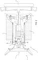
figure 2 is a view from the top, with parts removed for greater clarity, of the tracked vehicle offigure 1 ; -
figure 3 is a block diagram of a detail of the tracked vehicle offigure 1 ; -
figure 4 is a block diagram of a detail of a management system of the tracked vehicle offigure 1 . - With reference to
figure 1 ,number 1 defines, as a whole, a tracked vehicle for the preparation of ski slopes. The trackedvehicle 1 comprises aframe 2; a first track 3 (figure 2 ); a second track 4; a first drive wheel 5 (figure 2 ) and asecond drive wheel 6, which are independent of one another and are coupled to the first track 3 (figure 2 ) and to the second track 4, respectively; a group ofoperating devices 7; acontrol unit 17; aninterface 8, which can be operated by a user U and is coupled to thecontrol unit 17 so as to send inputs IN from the operator U to thecontrol unit 17; and a driver's cabin 9. - The
interface 8 can be a user interface arranged on the trackedvehicle 1 or it can be a transceiver interface to receive the inputs IN via radio. - In another preferred embodiment, the interface is a transceiver interface and is configured to receive in inputs IN via radio.
- The inputs IN sent via radio or entered through the user interface can be defined by a number sequence and/or a fingerprint or data concerning a fingerprint.
- The cabin 9 is configured to accommodate the operator U of the tracked
vehicle 1 and comprises adoor 15 comprising adoor lock 18, which is configured to be opened or closed with a door key and/or with a remote control. - In the case in point and with reference to
figure 2 , the group of operating devices 7 (figure 1 ) comprises amill 10; ablade 11; and a winch 12 (figure 1 ). - The
first drive wheel 5, thesecond drive wheel 6 and theoperating devices 7 define a group of utilities. - With reference to
figure 2 , the trackedvehicle 1 comprises a mechanicalpower generator assembly 13, which, in the example shown herein, is aninternal combustion engine 13 having a drive shaft 14 (which is schematically shown); apower transmission 16, which is operatively connected to thedrive shaft 14 and is designed to connect theinternal combustion engine 13 to the group of operating devices 7 (figure 1 ), to thefirst drive wheel 5 and to thesecond drive wheel 6. Thecontrol unit 17 is coupled to thegenerator assembly 13 and to thepower transmission 16 so as to control thegenerator assembly 13 and thepower transmission 16, respectively. - In an alternative version of the invention, which is not shown in the accompanying drawings, the mechanical power generator assembly comprises an electric motor, which replaces the internal combustion engine or cooperates with and is coupled to the internal combustion engine, thus forming a hybrid system.
- The
power transmission 16 is a power transmission comprising mechanical and/or hydraulic and/or electric elements. For example, thepower transmission 16 can comprise a mechanical transmission, hydraulic pumps, hydraulic ducts, hydraulic actuators, mechanical gears, shafts, electric generators and electric motors. - More in detail and in a non-limiting embodiment of the invention, the
power transmission 16 comprises at least one electric generator, which is mechanically coupled to the mechanical power generator assembly; and at least electric actuator, preferably an electric motor, which is operatively coupled to one of the operating devices and is electrically coupled to the electric generator. - In a non-limiting embodiment of the invention, the power transmission comprises at least one hydraulic pump, which is mechanically coupled to the internal combustion engine; and at least one hydraulic actuator, which is operatively coupled to one of the operating devices and is hydraulically coupled to the hydraulic pump.
- The
interface 8 is configured to receive the inputs IN from the operator U. - The
control unit 17 is coupled to theuser interface 8 so as to receive the inputs IN from the operator U through theuser interface 8. - The
control unit 17 is coupled to the mechanicalpower generator assembly 13 and is configured to start or turn off the mechanicalpower generator assembly 13. - The
user interface 8 comprises a keyboard and/or akeypad 20 to receive inputs from the user U and send them to thecontrol unit 17 in order to enter letter sequences, number sequences or any combination thereof. In another embodiment, theuser interface 8 comprises afingerprint sensor 23 to enter the inputs IN as fingerprints. In an embodiment, theuser interface 8 comprises both thekeypad 20 and thefingerprint sensor 23 and the inputs are a combination of fingerprints and numeric or alphanumeric sequences. - The
user interface 8 comprises astart command 19, for example a start button, which is connected to thecontrol unit 17 so as to the start the mechanicalpower generator assembly 13. - The
user interface 8 comprises adisplay 25 to show the inputs of the operator U and a state of the trackedvehicle 1. - In an alternative embodiment, the user interface comprises a touch screen display coupled to the control unit and through which it receives the inputs from the operator.
- In an alternative embodiment, the user interface comprises a selector and a display, which are coupled to the control unit so as to receive the inputs to be sent to the control unit and to be displayed on the display. The selector is a wheel selector or a joystick.
- Furthermore, the
control unit 17 comprises amemory 21 where a plurality of enabling inputs are stored. Each enabling input is a set of numeric characters. In another embodiment, the enabling input is a set of alphanumeric characters. In another embodiment, the enabling input is a set of letters of an alphabet. - Furthermore, the
control unit 17 is configured to define a state of the trackedvehicle 1, which, for example, is stored in thememory 21. The state of the trackedvehicle 1 can be: enabled starting or disabled starting. - The
control unit 17 is configured to compare the inputs IN entered by the operator U with the enabling inputs and, if the inputs IN correspond to one of the enabling inputs, change the state of the trackedvehicle 1 from disabled staring to enabled starting. - In a preferred - though not limiting - embodiment of the invention, each enabling input of the plurality of enabling inputs is associated with an enabling level. In use, the
control unit 17 is configured to enable the use of one ormore operating devices 7 based on the enabling level associated with the enabling input entered by the operator U. - Furthermore, the
control unit 17 is associated with thestart command 19 so as to receive a starting signal. Thecontrol unit 17 is configured to start the trackedvehicle 1 and, in particular, the mechanicalpower generator assembly 13, when it receives the starting command and the state of the tracked vehicle is enabled starting. In other words, the starting command causes the starting of the trackedvehicle 1 only if the state of the trackedvehicle 1 corresponds to enabled starting, whereas it does not cause the starting of the trackedvehicle 1 if the state of the tracked vehicle corresponds to disabled starting. - The
control unit 17 is configured to store the enabling input entered in thememory 17 and to compare at least one of the operating parameters of the trackedvehicle 1 detected during the use of the tracked vehicle with said enabling input entered, so as to monitor the type of use of the tracked vehicle of the user with which said enabling input entered is associated. The operating parameters are: a speed of the trackedvehicle 1; a speed of thefirst drive wheel 5 and/or of thesecond drive wheel 6, a speed of thewinch 12, jib angle of thewinch 12, position of control levers, weight of the vehicles, operating hours, fuel level, total fuel consumption, position, engine temperature, oil temperature, coolant temperature, error signals. As a consequence, thecontrol unit 17 creates a storing file in which there are stored one or more operating parameters of the trackedvehicle 1 and the enabling input entered, thus being able to track down the operator U who used the trackedvehicle 1 and how the trackedvehicle 1 was used. This information can be used for analysing the use of the trackedvehicle 1 and for possible analyses of damages to the trackedvehicle 1.
Furthermore, the control unit is configured to set, upon starting of the tracked vehicle, setting parameters of the tracked vehicle coupled with the input entered by the operator; preferably, the setting parameters are selected among: control parameters of devices housed in the cabin; control parameters of the vehicle; control parameters of theoperating devices 7. - More in detail, the control parameters of the devices present in the cabin comprise one or more of the following elements: setting of the windshield wipers, for example on, off, continuous, discontinuous, movement time interval; setting of the heating, i.e. on, off, time of activation of the heating cycle; setting of the user interface, for example brightness of the screen, brightness of the
selector 22, brightness of thekeypad 20, metric units or imperial units (British units), visibility of the speedometer; video camera parameters, i.e. on or off; operating parameters of the radio system. - The control parameters of the tracked vehicle comprise one or more of the following elements: parameters concerning the steering unit, i.e. setting parameters, reserve; parameters concerning the features of the accelerator pedal; management of the
generator assembly 13, i.e. type of control, maximum engine speed; parameters concerning the driver assistance system, i.e. sensitivity to the movement of the control levers in drive, neutral and rear position, automatic activation of the service brake, i.e. activation delay. - The control parameters of the
operating devices 7 comprise one or more of the following elements: control parameters of thefront operating device 7, in particular of theblade 11, more in detail type of control features of the control device, for example joystick; control parameters of therear operating device 7, in particular of themill 10, more in detail type of control, automatic operation of the mill lifting, automatic operating of the mill lowering, mill anti-stall system; control parameters of the winch, more in detail operating mode of the winch: automatic, manual, features of the winch. - In an alternative embodiment, the tracked
vehicle 1 comprises a transceiver device to transmit the enabling input and at least one of the operating parameters of the trackedvehicle 1 to a control centre.
The trackedvehicle 1 further comprises a radiodata transceiver unit 42 to transmit the enabling input entered and said at least operating parameter to a remote processing unit 41. - The invention also relates to a management system of a tracked vehicle comprising the tracked
vehicle 1 and a remote processing unit 41, which is coupled to theradio transceiver unit 42 so as to receive the data transmitted by theradio transceiver unit 42; the remote processing unit 41 comprising a display unit 43 to display the data of the trackedvehicle 1. - The invention further relates to a fleet of tracked
vehicles 1 comprising a plurality of trackedvehicles 1 of the type described above. One or more enabling inputs entered in thememory 21 of one of the trackedvehicles 1 can be the same as one or more enabling inputs entered in thememory 21 of one or more or all trackedvehicles 1 of the fleet of trackedvehicles 1. In this way, each operator U can access one or more or all tracked vehicles of the fleet of trackedvehicles 1 with the same enabling input. Furthermore, thanks to this invention, you can enter, in thememory 21 of thecontrol units 17 of all trackedvehicles 1, a same enabling input that is the same in all tracked vehicles, so that mechanics can use it the start the tracked vehicle and carry out maintenance works on the tracked vehicles. - In other words, in use, the operator U opens the door of the cabin 9 with the door key or with the remote control and then enters an input through the
interface 8. Thecontrol unit 17 compares the input entered with the enabling inputs stored in thememory 21 and, if the input entered corresponds to one of the enabling inputs stored, then it enables the starting of the mechanicalpower generator assembly 13. The operator U receive a successful enabling message through the display and presses the start command. Thecontrol unit 17 receives the signal from the start command and starts the mechanicalpower generator assembly 13; as a consequence, the operator U can use the trackedvehicle 1. During the use, thecontrol unit 17 stores at least one of the operating parameters and associates them with the enabling input entered. When the operator U wants to turn off the mechanicalpower generator assembly 13, he uses the start command again. Thecontrol unit 17 receives the signal from the start command and turn off the mechanicalpower generator assembly 13. The operator U can leave the cabin 9 and close thedoor 15 of the cabin 9 using the door key or the remote control. - In an alternative embodiment, the operator U enters the input IN through the
interface 8, which is in communication with a mobile transceiver device, for example a mobile phone or a remote control. The communication between the mobile transceiver device and the interface can be of the type using Bluetooth, Wan or a mobile cellular network. - The inputs can consist of a numeric sequence to be entered in the mobile phone or of a fingerprint detected by the mobile transceiver device.
- Thanks to the invention, the tracked
vehicle 1 can be turned on without the use of a dedicated key. Furthermore, the trackedvehicle 1 can be used by different operators U and can store, through the operating parameters of the trackedvehicle 1, the use of the trackedvehicle 1 made by each operator U. Finally, the operation of the trackedvehicle 1 can be limited to some functions or to all functions, based on the experience of the user U, through the use of the enabling levels associated with each enabling input.
Claims (14)
- Fleet of tracked vehicles comprising a plurality of tracked vehicles; each tracked vehicle (1) comprising a first and a second track (3, 4), a mechanical power generator assembly (13); an assembly of operating devices (7) coupled to the generator assembly (13); a first and a second drive wheel (5, 6) coupled respectively to the first and to the second track (3, 4), and to the generator assembly (13); an interface (8) to receive inputs (IN); and a control unit (17) coupled to the interface (8) to receive inputs (IN); the control unit (17) being coupled to the mechanical power generator assembly (13) and being configured to enable or disable starting of the mechanical power generator assembly (13) based on inputs (IN) received by the interface (8); wherein the control unit (17) of each tracked vehicle (1) comprises a memory (21) in which there are stored a plurality of enabling inputs; and at least one of the plurality of enabling inputs of the memories (21) of the respective tracked vehicles (1) is the same as the others; the control unit (17) is configured to compare the inputs (IN) with the plurality of enabling inputs and enables the starting of the tracked vehicle (1) if the inputs (IN) correspond to one of the enabling inputs of the plurality of enabling inputs; wherein each enabling input is associated with an enabling level; the control unit (17) being configured to enable one or more operating devices (7) based on the enabling level associated with the enabling input entered;
the control unit (17) being configured to store the enabling input entered and couple it with at least one operating parameter of the tracked vehicle (1) detected during the use of the tracked vehicle (1) to monitor the use of the tracked vehicle (1) coupled to the enabling input entered; the at least one operating parameter is selected from vehicle speed; drive wheel speed; winch speed, winch jib angle, position of command levers, vehicle weight, operating hours, fuel level, total fuel consumption, position, engine temperature, oil temperature, coolant temperature, error signals. - Fleet of tracked vehicles of claim 1, wherein the interface (8) is a user interface and comprises a keyboard and/or a keypad (20) and/or a fingerprint sensor (23) for entering the inputs (IN); preferably the inputs (IN) are defined by a number sequence and/or a fingerprint and/or data of a fingerprint.
- Fleet of tracked vehicles of claim 1, wherein the interface (8) is a transceiver interface and is configured to receive the inputs (IN) through radio signals; preferably the inputs (IN) sent through radio signals are defined by a number sequence and/or a fingerprint and/or data of a fingerprint.
- Fleet of tracked vehicles of any one of the preceding claims, wherein the control unit (17) comprises a memory (21) in which there is stored at least one enabling input; the control unit (17) being configured to compare the inputs (IN) with the at least one enabling input stored and in the case in which the inputs (IN) correspond to the at least one enabling input, to enable starting of the mechanical power generator assembly (13).
- Fleet of tracked vehicles of any one of the preceding claims, comprising a cab (9) configured to accommodate the operator (U) of the tracked vehicle (1); the cab (9) having a door (15) comprising a door lock (18) that is configured to be opened and/or closed with a key or with a remote control.
- Fleet of tracked vehicles of any one of the preceding claims, wherein the interface (8) comprises a start command (19) connected to the control unit (17) to start the mechanical power generator assembly (13); the control unit (17) being configured to start the mechanical power generator assembly (13) when it receives the start command (19) and the starting of the generator assembly (13) is enabled.
- Fleet of tracked vehicles of any one of the preceding claims, wherein the interface (8) comprises a touch screen display (25) coupled to the control unit (17) and through which it receives the inputs (IN) from the operator (U) .
- Fleet of tracked vehicles of any one of the preceding claims, comprises a selector (22) and a display (25) coupled to the control unit (17) to receive the inputs (IN) to be sent to the control unit (17) and to be viewed on the display (25), preferably the selector (22) being selected in a group comprising a wheel selector; a joystick selector; a touch pad on an armrest of the vehicle.
- Fleet of tracked vehicles of any one of the preceding claims, the control unit (17) being configured to set some setting parameters of the vehicle when the vehicle (1) is started; said setting parameters being defined by the input entered by the user (U); preferably the setting parameters are selected in a group comprising: control parameters of devices housed in cabin (9); control parameters of vehicle; control parameters of work devices (7).
- Fleet of tracked vehicles of the claim 1 or 9, comprising a data transceiver unit (42) to transmit to a remote processing unit (41) the enabling input entered and the at least operating parameter.
- Fleet of tracked vehicles according to any one of the claims from 1 to 10, wherein one or more enabling inputs entered in the memory (21) of one of the tracked vehicles (1) can be the same as one or more enabling inputs entered in the memory (21) of one or more or all tracked vehicles (1) of the fleet of tracked vehicles (1).
- Management system of a fleet of tracked vehicles comprising the fleet of tracked vehicle vehicles according to any one of the claims from 1 to 11, and a remote processing unit (41) coupled to the data transceiver unit (42) to receive data transmitted by the data transceiver unit (42); the remote processing unit (41) comprising a display unit (43) to display data of the fleet of tracked vehicles (1).
- Management system of a tracked vehicle comprising the tracked vehicle; the tracked vehicle (1) comprising a first and a second track (3, 4), a mechanical power generator assembly (13); an assembly of operating devices (7) coupled to the generator assembly (13); a first and a second drive wheel (5, 6) coupled respectively to the first and to the second track (3, 4), and to the generator assembly (13); an interface (8) to receive inputs (IN); and a control unit (17) coupled to the interface (8) to receive inputs (IN); the control unit (17) being coupled to the mechanical power generator assembly (13) and being configured to enable or disable starting of the mechanical power generator assembly (13) based on inputs (IN) received by the interface (8); wherein a memory (21) of the control unit (17) comprises a plurality of enabling inputs; the control unit (17) is configured to compare the inputs (IN) with the plurality of enabling inputs and enables the starting of the tracked vehicle (1) if the inputs (IN) correspond to one of the enabling inputs of the plurality of enabling inputs; wherein each enabling input is associated with an enabling level; the control unit (17) being configured to enable one or more operating devices (7) based on the enabling level associated with the enabling input entered;
the tracked vehicle comprising a data transceiver unit (42) to transmit to a remote processing unit (41) the enabling input entered and the at least operating parameter; the management system comprising the remote processing unit (41) coupled to the data transceiver unit (42) to receive data transmitted by the data transceiver unit (41); the control unit (17) being configured to store the enabling input entered and couple it with at least one operating parameter of the tracked vehicle (1) detected during the use of the tracked vehicle (1) to monitor the use of the tracked vehicle (1) coupled to the enabling input entered; the at least one operating parameter is selected from vehicle speed; drive wheel speed; winch speed, winch jib angle, position of command levers, vehicle weight, operating hours, fuel level, total fuel consumption, position, engine temperature, oil temperature, coolant temperature, error signals; the remote processing unit (41) comprising a display unit (43) to display data of the tracked vehicle (1). - Management system of a tracked vehicle comprising the tracked vehicle; the tracked vehicle (1) comprising a first and a second track (3, 4), a mechanical power generator assembly (13); an assembly of operating devices (7) coupled to the generator assembly (13); a first and a second drive wheel (5, 6) coupled respectively to the first and to the second track (3, 4), and to the generator assembly (13); an interface (8) to receive inputs (IN); and a control unit (17) coupled to the interface (8) to receive inputs (IN); the control unit (17) being coupled to the mechanical power generator assembly (13) and being configured to enable or disable starting of the mechanical power generator assembly (13) based on inputs (IN) received by the interface (8); wherein the memory (21) of the control unit (17) comprises a plurality of enabling inputs; the control unit (17) is configured to compare the inputs (IN) with the plurality of enabling inputs and enables the starting of the tracked vehicle (1) if the inputs (IN) correspond to one of the enabling inputs of the plurality of enabling inputs; wherein each enabling input is associated with an enabling level; the control unit (17) being configured to enable one or more operating devices (7) based on the enabling level associated with the enabling input entered;
the tracked vehicle comprising a data transceiver unit (42) to transmit to a remote processing unit (41) the enabling input entered and the at least operating parameter; the management system comprising the remote processing unit (41) coupled to the data transceiver unit (42) to receive data transmitted by the data transceiver unit (41); the control unit (17) being configured to set some setting parameters of the vehicle when the vehicle (1) is started; said setting parameters being defined by the input entered by the user (U); the setting parameters are selected in a group comprising: control parameters of devices housed in cabin (9); control parameters of vehicle; control parameters of work devices (7); the remote processing unit (41) comprising a display unit (43) to display data of the tracked vehicle (1).
Applications Claiming Priority (2)
| Application Number | Priority Date | Filing Date | Title |
|---|---|---|---|
| IT102017000007911A IT201700007911A1 (en) | 2017-01-25 | 2017-01-25 | TRACKED VEHICLE AND FLEET OF TRACKED VEHICLES |
| PCT/IB2018/050460 WO2018138671A1 (en) | 2017-01-25 | 2018-01-25 | Tracked vehicle and fleet of tracked vehicles |
Publications (3)
| Publication Number | Publication Date |
|---|---|
| EP3573865A1 EP3573865A1 (en) | 2019-12-04 |
| EP3573865B1 true EP3573865B1 (en) | 2023-09-27 |
| EP3573865C0 EP3573865C0 (en) | 2023-09-27 |
Family
ID=58779293
Family Applications (1)
| Application Number | Title | Priority Date | Filing Date |
|---|---|---|---|
| EP18704601.6A Active EP3573865B1 (en) | 2017-01-25 | 2018-01-25 | Fleet and fleet management system of tracked vehicles |
Country Status (7)
| Country | Link |
|---|---|
| US (1) | US12263808B2 (en) |
| EP (1) | EP3573865B1 (en) |
| CN (1) | CN108883742B (en) |
| CA (1) | CA3049747A1 (en) |
| IT (1) | IT201700007911A1 (en) |
| RU (1) | RU2754877C2 (en) |
| WO (1) | WO2018138671A1 (en) |
Families Citing this family (3)
| Publication number | Priority date | Publication date | Assignee | Title |
|---|---|---|---|---|
| DE102022206052A1 (en) * | 2022-06-15 | 2023-12-21 | Kässbohrer Geländefahrzeug Aktiengesellschaft | Tracked drive and civilian tracked vehicle |
| IT202300014697A1 (en) * | 2023-07-13 | 2025-01-13 | Prinoth Spa | TRACKED VEHICLE, TRACKED VEHICLE MONITORING AND/OR CONTROL AND/OR MANAGEMENT SYSTEM AND RELATED METHOD |
| JP7498347B1 (en) * | 2023-10-30 | 2024-06-11 | 株式会社竹内製作所 | User management system for work vehicles |
Citations (2)
| Publication number | Priority date | Publication date | Assignee | Title |
|---|---|---|---|---|
| US20070250920A1 (en) * | 2006-04-24 | 2007-10-25 | Jeffrey Dean Lindsay | Security Systems for Protecting an Asset |
| US20160304051A1 (en) * | 2015-04-20 | 2016-10-20 | Oshkosh Corporation | Response vehicle systems and methods |
Family Cites Families (48)
| Publication number | Priority date | Publication date | Assignee | Title |
|---|---|---|---|---|
| US5692052A (en) * | 1991-06-17 | 1997-11-25 | Nippondenso Co., Ltd. | Engine noise control apparatus |
| JP3094517B2 (en) * | 1991-06-28 | 2000-10-03 | 日産自動車株式会社 | Active noise control device |
| US5815826A (en) * | 1996-03-28 | 1998-09-29 | Caterpillar Inc. | Method for determining the productivity of an earth moving machines |
| US6381502B1 (en) * | 1998-10-19 | 2002-04-30 | Rockwell Technologies, Llc | Virtual tool box for use with industrial control system |
| US6249727B1 (en) * | 1999-05-19 | 2001-06-19 | Caterpillar Inc. | Method and apparatus for customizing and limiting operation of machine subsystems |
| JP2003085267A (en) * | 2001-09-10 | 2003-03-20 | Shin Caterpillar Mitsubishi Ltd | Body management system for working machine |
| US7302320B2 (en) * | 2001-12-21 | 2007-11-27 | Oshkosh Truck Corporation | Failure mode operation for an electric vehicle |
| US7327280B2 (en) * | 2002-08-15 | 2008-02-05 | California Institute Of Technology | Emergency vehicle traffic signal preemption system |
| US7298275B2 (en) * | 2002-09-27 | 2007-11-20 | Rockwell Automation Technologies, Inc. | Machine associating method and apparatus |
| US7272456B2 (en) * | 2003-01-24 | 2007-09-18 | Rockwell Automation Technologies, Inc. | Position based machine control in an industrial automation environment |
| US7043316B2 (en) * | 2003-02-14 | 2006-05-09 | Rockwell Automation Technologies Inc. | Location based programming and data management in an automated environment |
| US20050005167A1 (en) * | 2003-07-02 | 2005-01-06 | Kelly Thomas J. | Systems and methods for providing security operations in a work machine |
| KR100520451B1 (en) * | 2003-07-21 | 2005-10-13 | 인하대학교 산학협력단 | Controller for engine start and door lock of a car using keypad |
| US7015791B2 (en) * | 2003-08-19 | 2006-03-21 | General Motors Corporation | Keyless entry module and method |
| JP4156493B2 (en) * | 2003-11-04 | 2008-09-24 | 株式会社東海理化電機製作所 | Vehicle security device and ID code management device |
| US7650509B1 (en) * | 2004-01-28 | 2010-01-19 | Gordon & Howard Associates, Inc. | Encoding data in a password |
| US20050246040A1 (en) * | 2004-04-29 | 2005-11-03 | Caterpillar Inc. | Operator profile control system for a work machine |
| WO2006095876A1 (en) * | 2005-03-11 | 2006-09-14 | Yamaha Corporation | Engine sound processing device |
| JP4173891B2 (en) * | 2005-03-22 | 2008-10-29 | 本田技研工業株式会社 | Sound effect generator for moving objects |
| JP5197936B2 (en) * | 2006-08-02 | 2013-05-15 | ヤマハ発動機株式会社 | Vehicle control apparatus and vehicle equipped with the same |
| US8669845B1 (en) * | 2007-03-30 | 2014-03-11 | Vail Resorts, Inc. | RFID skier monitoring systems and methods |
| DE102007018246A1 (en) * | 2007-04-12 | 2008-10-16 | Kässbohrer Geländefahrzeug AG | vehicle |
| US8174555B2 (en) * | 2007-05-30 | 2012-05-08 | Eastman Kodak Company | Portable video communication system |
| US7928735B2 (en) * | 2007-07-23 | 2011-04-19 | Yung-Sheng Huang | Battery performance monitor |
| JP4384681B2 (en) * | 2007-07-25 | 2009-12-16 | 本田技研工業株式会社 | Active sound effect generator |
| US9299247B2 (en) * | 2008-01-14 | 2016-03-29 | Caterpillar Inc. | System and method for adjusting machine parameters |
| US8994494B2 (en) * | 2008-10-10 | 2015-03-31 | Polaris Industries Inc. | Vehicle security system |
| US8331196B2 (en) * | 2009-04-14 | 2012-12-11 | Covaris, Inc. | System and method for controlling an acoustic transducer |
| JP4967000B2 (en) * | 2009-06-30 | 2012-07-04 | 本田技研工業株式会社 | Sound effect generator |
| CA2801334C (en) * | 2010-06-03 | 2020-03-10 | Polaris Industries Inc. | Electronic throttle control |
| US8660738B2 (en) * | 2010-12-14 | 2014-02-25 | Catepillar Inc. | Equipment performance monitoring system and method |
| US9365188B1 (en) * | 2011-04-22 | 2016-06-14 | Angel A. Penilla | Methods and systems for using cloud services to assign e-keys to access vehicles |
| JP5804068B2 (en) * | 2011-08-31 | 2015-11-04 | トヨタ自動車株式会社 | Engine start control device for hybrid vehicle |
| US9043402B2 (en) * | 2011-09-19 | 2015-05-26 | Trimble Navigation Limited | Publication of equipment status |
| US20130321178A1 (en) * | 2012-05-29 | 2013-12-05 | Akhtar Jameel | Shared vehicle rental system including transmission of reservation information and targeted advertising |
| US8970352B2 (en) * | 2012-10-23 | 2015-03-03 | GM Global Technology Operations LLC | Remote activated garage door opener functions via a graphical user interface in a vehicle |
| RU2524809C2 (en) * | 2012-11-29 | 2014-08-10 | Общество с ограниченной ответственностью "Научно-производственное объединение "СтарЛайн" (ООО "НПО "СтарЛайн") | System for engine start access with safety functions and servicing built around immobiliser |
| US20140315164A1 (en) * | 2013-04-17 | 2014-10-23 | Caterpillar Inc. | System and method for improving operator performance |
| US9794652B2 (en) * | 2013-10-31 | 2017-10-17 | Delta Systems, Inc. | Smart monitoring system and method of operation |
| CN111942326A (en) * | 2013-12-11 | 2020-11-17 | 普瑞诺斯有限公司 | Snow groomers or other tracked vehicles and systems therefor |
| US10239489B2 (en) * | 2015-09-11 | 2019-03-26 | Dura Operating, Llc | Vehicle access system with inadvertent actuation control |
| KR101855335B1 (en) * | 2016-07-01 | 2018-05-08 | 주식회사 예일전자 | Apparatus for generating sound by using vehivle body |
| NL2018466B1 (en) * | 2016-09-22 | 2018-03-29 | Bolt Mobility B V | Scooter |
| WO2018116861A1 (en) * | 2016-12-22 | 2018-06-28 | ソニー株式会社 | Sound processing device, method, and program |
| US12142086B2 (en) * | 2017-01-05 | 2024-11-12 | Revivermx, Inc. | Digital license plate with geofencing support and road usage monitoring |
| US9947147B1 (en) * | 2017-03-04 | 2018-04-17 | TrueLite Trace, Inc. | Vehicle electronic logging authorization and handover system |
| US10655545B2 (en) * | 2017-06-30 | 2020-05-19 | Polaris Industries Inc. | Throttle actuator position verification |
| US10074358B1 (en) * | 2017-09-07 | 2018-09-11 | GM Global Technology Operations LLC | Audio control systems and methods for vehicles with variable compression ratio engines |
-
2017
- 2017-01-25 IT IT102017000007911A patent/IT201700007911A1/en unknown
-
2018
- 2018-01-25 WO PCT/IB2018/050460 patent/WO2018138671A1/en not_active Ceased
- 2018-01-25 CA CA3049747A patent/CA3049747A1/en active Pending
- 2018-01-25 EP EP18704601.6A patent/EP3573865B1/en active Active
- 2018-01-25 RU RU2019126466A patent/RU2754877C2/en active
- 2018-01-25 CN CN201880000093.4A patent/CN108883742B/en active Active
- 2018-01-25 US US16/475,605 patent/US12263808B2/en active Active
Patent Citations (2)
| Publication number | Priority date | Publication date | Assignee | Title |
|---|---|---|---|---|
| US20070250920A1 (en) * | 2006-04-24 | 2007-10-25 | Jeffrey Dean Lindsay | Security Systems for Protecting an Asset |
| US20160304051A1 (en) * | 2015-04-20 | 2016-10-20 | Oshkosh Corporation | Response vehicle systems and methods |
Also Published As
| Publication number | Publication date |
|---|---|
| US20190375370A1 (en) | 2019-12-12 |
| US12263808B2 (en) | 2025-04-01 |
| EP3573865C0 (en) | 2023-09-27 |
| CN108883742A (en) | 2018-11-23 |
| EP3573865A1 (en) | 2019-12-04 |
| RU2019126466A (en) | 2021-02-26 |
| CA3049747A1 (en) | 2018-08-02 |
| RU2019126466A3 (en) | 2021-03-10 |
| RU2754877C2 (en) | 2021-09-08 |
| WO2018138671A1 (en) | 2018-08-02 |
| CN108883742B (en) | 2022-12-30 |
| IT201700007911A1 (en) | 2018-07-25 |
Similar Documents
| Publication | Publication Date | Title |
|---|---|---|
| KR102132502B1 (en) | Excavator | |
| KR101508079B1 (en) | Information display device of construction machine, information display method of construction machine, and information display computer program of construction machine | |
| EP3573865B1 (en) | Fleet and fleet management system of tracked vehicles | |
| EP3351692B1 (en) | Shovel | |
| JP2017110472A (en) | Shovel | |
| GB2360500A (en) | A display, control and monitoring system for an industrial truck | |
| EP4084983B1 (en) | Tracked vehicle comprising a user interface | |
| KR20210139238A (en) | shovel | |
| KR20190120217A (en) | Shovel, shobel control method and mobile information terminal | |
| CN112888824A (en) | Display device of excavator | |
| JP2023004406A (en) | System and method for controlling work machine | |
| JP7498347B1 (en) | User management system for work vehicles | |
| JP2016022915A (en) | Service car | |
| JP2025075720A (en) | Shovel and operation control system for the same | |
| JP4741214B2 (en) | Operating parameter setting device | |
| US20230042126A1 (en) | Control of access to power machine functionality | |
| US12110663B2 (en) | Shovel | |
| EP4488455A1 (en) | Work machine | |
| KR101418658B1 (en) | Vehicles control device for vibrating start button and method thereof | |
| KR101338191B1 (en) | Convenience Functions Adjusting System and Adjusting Method thereof | |
| WO2025070227A1 (en) | Operation apparatus and operation system | |
| CN119987336A (en) | Remote control driving control method, device and system for crawler multifunctional platform |
Legal Events
| Date | Code | Title | Description |
|---|---|---|---|
| STAA | Information on the status of an ep patent application or granted ep patent |
Free format text: STATUS: UNKNOWN |
|
| STAA | Information on the status of an ep patent application or granted ep patent |
Free format text: STATUS: THE INTERNATIONAL PUBLICATION HAS BEEN MADE |
|
| PUAI | Public reference made under article 153(3) epc to a published international application that has entered the european phase |
Free format text: ORIGINAL CODE: 0009012 |
|
| STAA | Information on the status of an ep patent application or granted ep patent |
Free format text: STATUS: REQUEST FOR EXAMINATION WAS MADE |
|
| 17P | Request for examination filed |
Effective date: 20190718 |
|
| AK | Designated contracting states |
Kind code of ref document: A1 Designated state(s): AL AT BE BG CH CY CZ DE DK EE ES FI FR GB GR HR HU IE IS IT LI LT LU LV MC MK MT NL NO PL PT RO RS SE SI SK SM TR |
|
| AX | Request for extension of the european patent |
Extension state: BA ME |
|
| DAV | Request for validation of the european patent (deleted) | ||
| DAX | Request for extension of the european patent (deleted) | ||
| STAA | Information on the status of an ep patent application or granted ep patent |
Free format text: STATUS: EXAMINATION IS IN PROGRESS |
|
| 17Q | First examination report despatched |
Effective date: 20220503 |
|
| GRAP | Despatch of communication of intention to grant a patent |
Free format text: ORIGINAL CODE: EPIDOSNIGR1 |
|
| STAA | Information on the status of an ep patent application or granted ep patent |
Free format text: STATUS: GRANT OF PATENT IS INTENDED |
|
| INTG | Intention to grant announced |
Effective date: 20230418 |
|
| P01 | Opt-out of the competence of the unified patent court (upc) registered |
Effective date: 20230518 |
|
| GRAS | Grant fee paid |
Free format text: ORIGINAL CODE: EPIDOSNIGR3 |
|
| GRAA | (expected) grant |
Free format text: ORIGINAL CODE: 0009210 |
|
| STAA | Information on the status of an ep patent application or granted ep patent |
Free format text: STATUS: THE PATENT HAS BEEN GRANTED |
|
| AK | Designated contracting states |
Kind code of ref document: B1 Designated state(s): AL AT BE BG CH CY CZ DE DK EE ES FI FR GB GR HR HU IE IS IT LI LT LU LV MC MK MT NL NO PL PT RO RS SE SI SK SM TR |
|
| REG | Reference to a national code |
Ref country code: GB Ref legal event code: FG4D |
|
| REG | Reference to a national code |
Ref country code: CH Ref legal event code: EP |
|
| REG | Reference to a national code |
Ref country code: DE Ref legal event code: R096 Ref document number: 602018058222 Country of ref document: DE |
|
| REG | Reference to a national code |
Ref country code: IE Ref legal event code: FG4D |
|
| U01 | Request for unitary effect filed |
Effective date: 20231024 |
|
| U07 | Unitary effect registered |
Designated state(s): AT BE BG DE DK EE FI FR IT LT LU LV MT NL PT SE SI Effective date: 20231031 |
|
| P04 | Withdrawal of opt-out of the competence of the unified patent court (upc) registered |
Effective date: 20231027 |
|
| PG25 | Lapsed in a contracting state [announced via postgrant information from national office to epo] |
Ref country code: GR Free format text: LAPSE BECAUSE OF FAILURE TO SUBMIT A TRANSLATION OF THE DESCRIPTION OR TO PAY THE FEE WITHIN THE PRESCRIBED TIME-LIMIT Effective date: 20231228 |
|
| PG25 | Lapsed in a contracting state [announced via postgrant information from national office to epo] |
Ref country code: RS Free format text: LAPSE BECAUSE OF FAILURE TO SUBMIT A TRANSLATION OF THE DESCRIPTION OR TO PAY THE FEE WITHIN THE PRESCRIBED TIME-LIMIT Effective date: 20230927 Ref country code: NO Free format text: LAPSE BECAUSE OF FAILURE TO SUBMIT A TRANSLATION OF THE DESCRIPTION OR TO PAY THE FEE WITHIN THE PRESCRIBED TIME-LIMIT Effective date: 20231227 Ref country code: HR Free format text: LAPSE BECAUSE OF FAILURE TO SUBMIT A TRANSLATION OF THE DESCRIPTION OR TO PAY THE FEE WITHIN THE PRESCRIBED TIME-LIMIT Effective date: 20230927 Ref country code: GR Free format text: LAPSE BECAUSE OF FAILURE TO SUBMIT A TRANSLATION OF THE DESCRIPTION OR TO PAY THE FEE WITHIN THE PRESCRIBED TIME-LIMIT Effective date: 20231228 |
|
| U20 | Renewal fee for the european patent with unitary effect paid |
Year of fee payment: 7 Effective date: 20240115 |
|
| PG25 | Lapsed in a contracting state [announced via postgrant information from national office to epo] |
Ref country code: IS Free format text: LAPSE BECAUSE OF FAILURE TO SUBMIT A TRANSLATION OF THE DESCRIPTION OR TO PAY THE FEE WITHIN THE PRESCRIBED TIME-LIMIT Effective date: 20240127 |
|
| PG25 | Lapsed in a contracting state [announced via postgrant information from national office to epo] |
Ref country code: ES Free format text: LAPSE BECAUSE OF FAILURE TO SUBMIT A TRANSLATION OF THE DESCRIPTION OR TO PAY THE FEE WITHIN THE PRESCRIBED TIME-LIMIT Effective date: 20230927 |
|
| PG25 | Lapsed in a contracting state [announced via postgrant information from national office to epo] |
Ref country code: SM Free format text: LAPSE BECAUSE OF FAILURE TO SUBMIT A TRANSLATION OF THE DESCRIPTION OR TO PAY THE FEE WITHIN THE PRESCRIBED TIME-LIMIT Effective date: 20230927 Ref country code: RO Free format text: LAPSE BECAUSE OF FAILURE TO SUBMIT A TRANSLATION OF THE DESCRIPTION OR TO PAY THE FEE WITHIN THE PRESCRIBED TIME-LIMIT Effective date: 20230927 Ref country code: IS Free format text: LAPSE BECAUSE OF FAILURE TO SUBMIT A TRANSLATION OF THE DESCRIPTION OR TO PAY THE FEE WITHIN THE PRESCRIBED TIME-LIMIT Effective date: 20240127 Ref country code: ES Free format text: LAPSE BECAUSE OF FAILURE TO SUBMIT A TRANSLATION OF THE DESCRIPTION OR TO PAY THE FEE WITHIN THE PRESCRIBED TIME-LIMIT Effective date: 20230927 Ref country code: CZ Free format text: LAPSE BECAUSE OF FAILURE TO SUBMIT A TRANSLATION OF THE DESCRIPTION OR TO PAY THE FEE WITHIN THE PRESCRIBED TIME-LIMIT Effective date: 20230927 Ref country code: SK Free format text: LAPSE BECAUSE OF FAILURE TO SUBMIT A TRANSLATION OF THE DESCRIPTION OR TO PAY THE FEE WITHIN THE PRESCRIBED TIME-LIMIT Effective date: 20230927 |
|
| PG25 | Lapsed in a contracting state [announced via postgrant information from national office to epo] |
Ref country code: PL Free format text: LAPSE BECAUSE OF FAILURE TO SUBMIT A TRANSLATION OF THE DESCRIPTION OR TO PAY THE FEE WITHIN THE PRESCRIBED TIME-LIMIT Effective date: 20230927 |
|
| REG | Reference to a national code |
Ref country code: DE Ref legal event code: R097 Ref document number: 602018058222 Country of ref document: DE |
|
| PLBE | No opposition filed within time limit |
Free format text: ORIGINAL CODE: 0009261 |
|
| STAA | Information on the status of an ep patent application or granted ep patent |
Free format text: STATUS: NO OPPOSITION FILED WITHIN TIME LIMIT |
|
| PG25 | Lapsed in a contracting state [announced via postgrant information from national office to epo] |
Ref country code: MC Free format text: LAPSE BECAUSE OF FAILURE TO SUBMIT A TRANSLATION OF THE DESCRIPTION OR TO PAY THE FEE WITHIN THE PRESCRIBED TIME-LIMIT Effective date: 20230927 |
|
| PG25 | Lapsed in a contracting state [announced via postgrant information from national office to epo] |
Ref country code: MC Free format text: LAPSE BECAUSE OF FAILURE TO SUBMIT A TRANSLATION OF THE DESCRIPTION OR TO PAY THE FEE WITHIN THE PRESCRIBED TIME-LIMIT Effective date: 20230927 |
|
| 26N | No opposition filed |
Effective date: 20240628 |
|
| GBPC | Gb: european patent ceased through non-payment of renewal fee |
Effective date: 20240125 |
|
| PG25 | Lapsed in a contracting state [announced via postgrant information from national office to epo] |
Ref country code: GB Free format text: LAPSE BECAUSE OF NON-PAYMENT OF DUE FEES Effective date: 20240125 |
|
| PG25 | Lapsed in a contracting state [announced via postgrant information from national office to epo] |
Ref country code: GB Free format text: LAPSE BECAUSE OF NON-PAYMENT OF DUE FEES Effective date: 20240125 |
|
| P05 | Withdrawal of opt-out of the competence of the unified patent court (upc) changed |
Free format text: CASE NUMBER: APP_583688/2023 Effective date: 20231031 |
|
| PG25 | Lapsed in a contracting state [announced via postgrant information from national office to epo] |
Ref country code: IE Free format text: LAPSE BECAUSE OF NON-PAYMENT OF DUE FEES Effective date: 20240125 |
|
| PG25 | Lapsed in a contracting state [announced via postgrant information from national office to epo] |
Ref country code: IE Free format text: LAPSE BECAUSE OF NON-PAYMENT OF DUE FEES Effective date: 20240125 |
|
| U20 | Renewal fee for the european patent with unitary effect paid |
Year of fee payment: 8 Effective date: 20250120 |
|
| PG25 | Lapsed in a contracting state [announced via postgrant information from national office to epo] |
Ref country code: CY Free format text: LAPSE BECAUSE OF FAILURE TO SUBMIT A TRANSLATION OF THE DESCRIPTION OR TO PAY THE FEE WITHIN THE PRESCRIBED TIME-LIMIT; INVALID AB INITIO Effective date: 20180125 |
|
| PG25 | Lapsed in a contracting state [announced via postgrant information from national office to epo] |
Ref country code: HU Free format text: LAPSE BECAUSE OF FAILURE TO SUBMIT A TRANSLATION OF THE DESCRIPTION OR TO PAY THE FEE WITHIN THE PRESCRIBED TIME-LIMIT; INVALID AB INITIO Effective date: 20180125 |
|
| PG25 | Lapsed in a contracting state [announced via postgrant information from national office to epo] |
Ref country code: TR Free format text: LAPSE BECAUSE OF FAILURE TO SUBMIT A TRANSLATION OF THE DESCRIPTION OR TO PAY THE FEE WITHIN THE PRESCRIBED TIME-LIMIT Effective date: 20230927 |
|
| REG | Reference to a national code |
Ref country code: CH Ref legal event code: U11 Free format text: ST27 STATUS EVENT CODE: U-0-0-U10-U11 (AS PROVIDED BY THE NATIONAL OFFICE) Effective date: 20260201 |
|
| U20 | Renewal fee for the european patent with unitary effect paid |
Year of fee payment: 9 Effective date: 20260108 |
|
| PGFP | Annual fee paid to national office [announced via postgrant information from national office to epo] |
Ref country code: CH Payment date: 20260201 Year of fee payment: 9 |