EP3573293A1 - Reduzieren oder eliminieren von routing-mikroschleifen in netzwerken mit clos-topologie wie etwa datencenter-clos-netzwerke unter verwendung des aussengrenzen-gateway-protokolls - Google Patents
Reduzieren oder eliminieren von routing-mikroschleifen in netzwerken mit clos-topologie wie etwa datencenter-clos-netzwerke unter verwendung des aussengrenzen-gateway-protokolls Download PDFInfo
- Publication number
- EP3573293A1 EP3573293A1 EP19160188.9A EP19160188A EP3573293A1 EP 3573293 A1 EP3573293 A1 EP 3573293A1 EP 19160188 A EP19160188 A EP 19160188A EP 3573293 A1 EP3573293 A1 EP 3573293A1
- Authority
- EP
- European Patent Office
- Prior art keywords
- next hop
- datagram
- interface
- egress interface
- node
- Prior art date
- Legal status (The legal status is an assumption and is not a legal conclusion. Google has not performed a legal analysis and makes no representation as to the accuracy of the status listed.)
- Granted
Links
Images






Classifications
-
- H—ELECTRICITY
- H04—ELECTRIC COMMUNICATION TECHNIQUE
- H04L—TRANSMISSION OF DIGITAL INFORMATION, e.g. TELEGRAPHIC COMMUNICATION
- H04L45/00—Routing or path finding of packets in data switching networks
- H04L45/22—Alternate routing
-
- H—ELECTRICITY
- H04—ELECTRIC COMMUNICATION TECHNIQUE
- H04L—TRANSMISSION OF DIGITAL INFORMATION, e.g. TELEGRAPHIC COMMUNICATION
- H04L45/00—Routing or path finding of packets in data switching networks
- H04L45/02—Topology update or discovery
- H04L45/033—Topology update or discovery by updating distance vector protocols
-
- H—ELECTRICITY
- H04—ELECTRIC COMMUNICATION TECHNIQUE
- H04L—TRANSMISSION OF DIGITAL INFORMATION, e.g. TELEGRAPHIC COMMUNICATION
- H04L45/00—Routing or path finding of packets in data switching networks
- H04L45/02—Topology update or discovery
- H04L45/04—Interdomain routing, e.g. hierarchical routing
-
- H—ELECTRICITY
- H04—ELECTRIC COMMUNICATION TECHNIQUE
- H04L—TRANSMISSION OF DIGITAL INFORMATION, e.g. TELEGRAPHIC COMMUNICATION
- H04L45/00—Routing or path finding of packets in data switching networks
- H04L45/18—Loop-free operations
-
- H—ELECTRICITY
- H04—ELECTRIC COMMUNICATION TECHNIQUE
- H04L—TRANSMISSION OF DIGITAL INFORMATION, e.g. TELEGRAPHIC COMMUNICATION
- H04L45/00—Routing or path finding of packets in data switching networks
- H04L45/20—Hop count for routing purposes, e.g. TTL
-
- H—ELECTRICITY
- H04—ELECTRIC COMMUNICATION TECHNIQUE
- H04L—TRANSMISSION OF DIGITAL INFORMATION, e.g. TELEGRAPHIC COMMUNICATION
- H04L45/00—Routing or path finding of packets in data switching networks
- H04L45/24—Multipath
-
- H—ELECTRICITY
- H04—ELECTRIC COMMUNICATION TECHNIQUE
- H04L—TRANSMISSION OF DIGITAL INFORMATION, e.g. TELEGRAPHIC COMMUNICATION
- H04L45/00—Routing or path finding of packets in data switching networks
- H04L45/28—Routing or path finding of packets in data switching networks using route fault recovery
-
- H—ELECTRICITY
- H04—ELECTRIC COMMUNICATION TECHNIQUE
- H04L—TRANSMISSION OF DIGITAL INFORMATION, e.g. TELEGRAPHIC COMMUNICATION
- H04L45/00—Routing or path finding of packets in data switching networks
- H04L45/50—Routing or path finding of packets in data switching networks using label swapping, e.g. multi-protocol label switch [MPLS]
-
- H—ELECTRICITY
- H04—ELECTRIC COMMUNICATION TECHNIQUE
- H04L—TRANSMISSION OF DIGITAL INFORMATION, e.g. TELEGRAPHIC COMMUNICATION
- H04L45/00—Routing or path finding of packets in data switching networks
- H04L45/74—Address processing for routing
- H04L45/745—Address table lookup; Address filtering
-
- H—ELECTRICITY
- H04—ELECTRIC COMMUNICATION TECHNIQUE
- H04L—TRANSMISSION OF DIGITAL INFORMATION, e.g. TELEGRAPHIC COMMUNICATION
- H04L49/00—Packet switching elements
- H04L49/15—Interconnection of switching modules
- H04L49/1515—Non-blocking multistage, e.g. Clos
Definitions
- the present disclosure concerns networks having a CLOS topology, such as networks used in data centers for allowing servers to communicate with one another. More specifically, the present disclosure concerns the potential problem of routing micro-loops in the event of a failed link (or a failed interface or a failed node terminating a link, all of which are commonly referred to as a "failed link" absent further specificity) in a CLOS network.
- servers 110a-110d can communicate with one another via nodes (e.g., routers, switches, etc.) 122 in an "access” or “top-of-rack” (TOR) layer 120, nodes 132 in a “distribution” layer 130, and nodes 142 in a “core” layer 140.
- the three layers 120, 130, 140 are connected to each other via layer 2 (L2) (in the sense of the Open Systems Interconnect (OSI) seven-layer model) links.
- L2 protocols such as the spanning tree protocol (STP) for example.
- the traditional data center network architecture 100 was developed based on an assumption that most of the traffic in a data center flows in user-server and server-user (commonly referred to as a "north-south") directions. That is, the assumption was that north-south traffic would be greater than server-to-server (commonly referred to as "east-west”) traffic. Although the foregoing assumption remains valid for some service provider data centers, with new Content Delivery Networks (CDNs), the majority of traffic in large scale data centers is east-west traffic, and this trend from north-south traffic to east-west traffic is expected to continue.
- Server-to-server (east-west) traffic e.g., App-Database, App-Web, VM migration, Data Replication
- inter-vLAN virtual local area network, or virtual LAN
- intra-vLAN traffic can be handled by the distribution layer 130. This means the number of hops, and therefore the latency, of traffic will vary based on the type of communication.
- the consistency of these two related parameters has become more critical than before, and the classic tree-based architecture such as that of Figure 1 does not provide such consistency.
- the traditional data center network architecture 100 may be unable to scale due to port/card/device/bandwidth limitations. Adding new devices to the distribution layer 130 will result in adding new devices to the core layer 140 at some point, because the core layer 140 has to be adjusted based on the increased bandwidth requirements of the lower layers 130 and/or 120. This means that the data center has to scale vertically, since it was developed based on north-south traffic considerations.
- STP is designed to prevent loops from being created when there are redundant paths in the network.
- Vendor-specific alternatives to STP include virtual PortChannel (vPC) from Cisco, QFabric from Juniper Networks, Fabric Path from Cisco, Multi chassis Link Aggregation (MLAG), Virtual Cluster Switching (VCS) from Brocade and Transparent Interconnection of Lots of Links (TRILL) from the IETF.
- vPC virtual PortChannel
- MLAG Multi chassis Link Aggregation
- VCS Virtual Cluster Switching
- TRILL Transparent Interconnection of Lots of Links
- FIG. 2 illustrates the use of a CLOS network topology to interconnect servers 210 in a data center environment 200.
- the CLOS network includes a spine layer 230 and a leaf layer 220.
- the servers 210a-210h are connected to leaf nodes (e.g., switches, routers, etc.) 222a-222d (also referred to as Top of Rack nodes, or TOR nodes), and each leaf node 222a-22d is connected to all spine nodes 232a-232d. There are no direct leaf-to-leaf, or spine-to-spine connections.
- the CLOS network topology has a number of advantages.
- each server is three hops away from any of the other servers in a three-stage CLOS topology.
- This topology be expanded to 5-stage CLOS topology by dividing the topology into clusters and adding another top-spine layer (also known as a super-spine layer), in which case each server would be five hops away from any of the other servers.)
- top-spine layer also known as a super-spine layer
- Multi-Chassis Link Aggregation Group (MLAG or MCLAG) is available on the server side. That is, any of the servers 210a-210h can be connected to two (or more) different leaf or TOR nodes 222 in order to have redundancy and/or load balancing capability.
- the connectivity matrix is quite complex in this topology, failures can be handled gracefully. For example, even if any three of the four spine nodes 232a-232d were to go down simultaneously, connectivity between each of the servers 210a-210h would remain.
- the CLOS topology scales horizontally, which is very cost effective.
- the bandwidth capacity between servers 210a-201h can be increased by adding more spine-leaf links, as well as adding more spine nodes 232.
- newly added spine nodes 232 will be connected to each leaf node 222, server-to-server bandwidth/throughput will increase significantly.
- This attribute makes CLOS network topologies more cost effective than the traditional data center network topology because spine nodes do not have to be big and expensive (as opposed to the core nodes 142 in Figure 1 , which do have to be big and expensive) when scaling in the traditional design.
- spine nodes 232 with a high number of ports could be used in the spine layer 230.
- a 5-stage, 7-stage, or a multiple pod architecture could be used.
- L3 routing When compared to L2 switching, layer 3 (L3) routing has many benefits, not only for scalability and resiliency, but also for visibility (which is quite important to the planning and operation teams).
- Figure 3 illustrates an example environment 300 using a CLOS network topology in which TOR nodes 315 are separated from the leaf layer 320, and in which the spine layer 330 to leaf layer 320 connections are L3 connections (indicated by solid lines).
- TOR instances 315 1,2 are connected to leaf instances 320 1,2 with L2 links (indicated by dashed lines).
- MLAG enables operators to utilize all the links and create bandwidth aggregation to leaf nodes.
- the environment 300 has some disadvantages.
- the size of L2 domains should be limited due to the difficulty in troubleshooting L2 environments.
- Figure 4 illustrates an example environment 400 in which L3 routing is deployed all the way down to the TOR nodes 315.
- the L3 connections are indicated by solid lines.
- the exterior Border Gateway Protocol (eBGP) (See, e.g., RFC 4271 and its extensions from the IETF, each of which is incorporated herein by reference.) is often used as the L3 routing protocol in CLOS topology networks in data centers.
- BGP is better than interior gateway protocols (IGPs) (such as OSPF and IS-IS) when dealing with a high number of prefixes, and it has a limited event propagation scope.
- IGP interior gateway protocols
- IGP will propagate link state changes throughout the network, even to the irrelevant nodes which are not impacted.
- BGP would still likely remain in the data center, most likely at the edge. This means that IGP were used, there would be two routing protocols running.
- BGP With its attributes and filters, BGP provides much better flexibility on controlling the traffic, and it provides per-hop traffic engineering capability than IGP. BGP autonomous system (AS) path visibility also helps operators troubleshoot problems more easily than with IGP. Further, BGP can be extended across data centers and used as a control plane protocol (e.g., EVPN) for VXLAN overlays. This provides many benefits such as active/active multi-homing. By default, IGP is more compatible with equal cost multipath routing (ECMP), where BGP configuration should be adjusted to meet the load balancing requirements.
- ECMP equal cost multipath routing
- route reflection between nodes can cause problems if iBGP is used. More specifically, spine switches can be declared as route reflectors, but can be problematic if ECMP paths are desired since route reflectors reflect only the best paths.
- the BGP add-path feature has to be enabled to push all routes to the leaves.
- AS_Path Multipath Relax Multi-AS Pathing
- BGP has extensive capabilities on per-hop traffic engineering. With iBGP, it is possible to use some part of this capability but eBGP's attributes provide better visibility, such as directly comparing BGP-Local-RIB to Adj-RIB-In and Adj-RIB-Out. In terms of traffic engineering and troubleshooting, eBGP it is better than iBGP.
- each leaf instance (pod) 320 1 ' and 320 2 ' and each TOR node (e.g., router, switch, etc.) 315a1'-315b2' has its own AS number. This avoids path hunting issues in BGP.
- the example topology 400 of Figure 4 is multiple pod/instance design. Such a design reduces the number of links between the leaf layer 320' and the spine layer 330. It also allows operators to put more than one leaf node in each AS. This type of arrangement is common, especially in large data center networks.
- server A 310a to server H 310h. There are four different paths, and each of them has the same AS_Path attribute (since each goes through node 315a1', leaf instance 1 320 1 ', spine 330, leaf instance 2 320 2 ' and node 315b2'). If the other attributes are also the same, BGP can utilize all ECMP paths by enabling multi-path functionality.
- each leaf node 320a1'-320b2' has its own AS number, and/or if servers are connected to more than one TOR node for redundancy.
- the length of each AS Path attribute would be the same, this does not suffice for using multi-paths in BGP because in order for BGP to route traffic over multiple paths, all attributes have to be the same, including the content of the AS Path attribute.
- the "AS Path multi-path relax" feature needs to be enabled to let BGP ignore the content of the AS Path attribute, while installing multiple best routes (as long as the length is identical).
- ASNs private AS numbers
- TOR ASNs can be used more than once.
- BGP Allow-AS-In feature needs to be enabled on TOR switches, which will turn off one of BGP's main loop avoidance mechanisms, and TOR switches will accept the routes even though they see their own ASN in received updates.
- an ASN may be used by multiple leaf nodes in an instance/pod. To avoid the potential for black holes created by such summarization when a specific prefix is withdrawn on the TOR side, specific prefixes should not be hidden.
- Section 7.5 of RFC 7938 discusses the potential problem of routing micro-loops in a CLOS topology network running eBGP. More specifically, when a downstream device, (e.g., Tier 2 device such as a leaf node 320a1'-320b2', loses all paths for a given prefix, it normally has the default route pointing toward an upstream device (e.g., a Tier 1 device such as a spine node 332a-332d).
- a downstream device e.g., Tier 2 device such as a leaf node 320a1'-320b2'
- a Tier 1 device such as a spine node 332a-332d
- a transient micro-loop becomes possible, since the Tier 1 node 330 will keep passing packets with the affected prefix back to the Tier 2 node 320, and the Tier 2 node 320 will bounce such packets back again using the default route to the upstream Tier 1 node 330.
- This micro-loop might last for the time it takes the upstream device to fully update its forwarding tables (or for the time it takes ECMP to select another route).
- RFC 7938 proposes configuring Tier 2 nodes 320 and Tier 1 nodes 330 with static "discard" or "null" routes that will be more specific than the default route for prefixes missing during network convergence.
- Tier 2 nodes 320 RFC 7938 notes that the discard route should be a summary route, covering all server subnets of the underlying Tier 3 nodes (e.g., TOR nodes) 310.
- Tier 1 nodes 330 RFC 7938 notes that the discard route should be a summary covering the server IP address subnets allocated for the whole data center. Those discard routes will only take precedence for the duration of network convergence, until the node learns a more specific prefix via a new path.
- routing micro-loops discards packets rather than having them loop. This can be considered a "lesser of two evils" approach.
- routing micro-loops could be avoided in a better way (e.g., in a way that avoids discarding or otherwise dropping packets).
- the problem of routing micro-loops in networks having a CLOS topology such as data center CLOS networks (e.g., in which nodes of the network are arranged in at least three (3) tiers) employing the exterior border gateway protocol (eBGP) for example, may be solved by: (a) receiving, on an interface of one of the nodes, a datagram, the datagram including destination information; (b) determining a next hop and an egress interface using (1) an identifier of the interface on which the datagram was received, (2) the destination information of the received datagram, and (3) stored forwarding information such that a routing micro-loop is avoided without discarding the datagram; and (c) forwarding the datagram via the egress interface.
- eBGP exterior border gateway protocol
- the act of determining a next hop and an egress interface includes performing a single lookup using the destination information and the interface on which the datagram was received to select the egress interface and a next hop.
- the problem of routing micro-loops in networks having a CLOS topology such as data center CLOS networks (e.g., in which nodes of the network are arranged in at least three (3) tiers) employing the exterior border gateway protocol (eBGP) for example, may be solved by: (a) receiving, on an interface of a node of the CLOS network, a datagram, the datagram including destination information; (b) looking up, using the destination information of the received datagram and stored forwarding information, a next hop egress interface on the node; (c) determining whether or not the next hop egress interface on the node is the same as the interface on which the datagram was received; and (d) responsive to a determination that the next hop egress interface on the node is the same as the interface on which the datagram was received, (1) replacing the next hop egress interface with a safe multipath next hop egress interface, and (2) forwarding the datagram via the safe multipath next hop egress
- eBGP exterior border gateway protocol
- the present disclosure may involve novel methods, apparatus, message formats, and/or data structures for reducing or eliminating routing micro-loops in networks having a CLOS topology, such as data center CLOS networks employing the exterior border gateway protocol (eBGP) for example.
- eBGP exterior border gateway protocol
- BGP speaker A router that implements BGP.
- Exterior BGP (or eBGP): A BGP connection between external peers (that is, peers within different ASes).
- FIB Forwarding Information Base
- Interior BGP (or iBGP): A BGP connection between internal peers (that is, peers within the same AS).
- Interior Gateway Protocol (or "IGP"): A routing protocol used to exchange routing information among routers within a single Autonomous System (AS).
- next Hop A next node (e.g., switch or router) to which a packet is sent from any given router as it traverses a network on its way to its final destination.
- next node e.g., switch or router
- Prefix part of an address that defines part of a communications network (e.g., a subnetwork), such as an Internet Protocol (“IP”) network for example.
- IP Internet Protocol
- Ring A unit of information that pairs a set of destinations with the attributes of a path to those destinations.
- the set of destinations are systems whose IP addresses are contained in one IP address prefix.
- Figure 5A is a flow diagram of an example method for reducing or eliminating routing micro-loops in a network having a CLOS topology.
- the nodes of the network are arranged in at least three (3) tiers.
- the example method 500 may be performed by a node (e.g., a switch or a router) in the network.
- the main steps of the example method 500 are performed when a datagram (e.g., a packet) is received on an interface of the node.
- the datagram includes destination information.
- the destination information may be a layer 3 destination address, such as an Internet Protocol (IP) address of one of the servers in a data center for example.
- IP Internet Protocol
- the example method 500 determines a next hop and an egress interface using (1) an identifier of the interface on which the datagram was received, (2) the destination information of the received datagram, and (3) stored forwarding information such that a routing micro-loop is avoided without discarding the datagram. (Block 520) That is, the example method 500 determines a next hop and an egress interface such that the egress interface is not the same as the interface on which the datagram was received. The method 500 then forwards the datagram via the egress interface (Block 530) before the method 500 is left (Node 540).
- FIG. 5B is a flow diagram of another example method 500' (which is consistent with the method 500 of Figure 5A ) for reducing or eliminating micro-loops in a network having a CLOS topology, in a manner consistent with the present disclosure.
- the nodes of the network are arranged in at least three (3) tiers.
- the example method 500' may be performed by a node (e.g., a switch or a router) in the network.
- event trigger 510 the main steps of the example method 500' are performed when a datagram (e.g., a packet) is received on an interface of the node.
- the datagram includes destination information.
- the destination information may be a layer 3 destination address, such as an Internet Protocol (IP) address of one of the servers in a data center for example.
- IP Internet Protocol
- the example method 500' looks up, using the destination information of the received datagram and stored forwarding information, a next hop egress interface on the node.
- the stored forwarding information may include, for example, a plurality of entries, each including a destination address prefix, a next hop node, a next hop egress interface and one or more safe multipath next hop interfaces.
- the example method 500' determines whether or not the next hop egress interface on the node is the same as the interface on which the datagram was received. (Decision 524) Responsive to a determination that the next hop egress interface on the node is the same as the interface on which the datagram was received (Decision 524, YES), the example method 500' (1) replaces the next hop egress interface with a safe multipath next hop egress interface (Block 526), and (2) forwards the datagram via the safe multipath next hop egress interface (Block 532), before the example method 500' is left (Node 540).
- the example method 500' forwards the datagram via the next hop egress interface (Block 534) before the example method 500' is left (Node 540).
- the destination information is a layer-3 destination address.
- the destination address may be a layer-3 destination address (e.g., Internet Protocol version 4 (IPv4), or Internet Protocol version 6 (IPv6) address) of a server linked with at least one top-of-rack node of the network.
- IPv4 Internet Protocol version 4
- IPv6 Internet Protocol version 6
- the loops are routing micro-loops between nodes of adjacent tiers in the CLOS network.
- the nodes of the network run a border gateway protocol (BGP), such as an exterior border gateway protocol (eBGP) for example.
- BGP border gateway protocol
- eBGP exterior border gateway protocol
- the node executing the method is located in a tier other than the third tier, such as in a tier other than the top-of-rack tier for example.
- the act of replacing the next hop egress interface with a safe multipath next hop egress interface includes selecting one of a plurality of safe next hop interfaces in such a manner that the plurality of safe next hop interfaces are selected with an even distribution.
- the act of replacing the next hop egress interface with a safe multipath next hop egress interface includes selecting one of a plurality of safe next hop interfaces in a round-robin manner.
- the act of replacing the next hop egress interface with a safe multipath next hop egress interface includes selecting one of a plurality of safe next hop interfaces randomly.
- each of the plurality of safe next hop interfaces is stored on the node in association with a prefix matching the destination information.
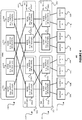
- FIG. 6 illustrates an example network 600 having a CLOS topology.
- the network 600 includes a TOR (or Tier 3) level 315', a leaf (or Tier 2) level 320' and a spine (or Tier 1) level 330.
- the TOR level 315' includes nodes T1 315a1', T2 315b1', T3 315a2' and T4 315b2'.
- the leaf level 320' includes nodes E1 320a1', E2 320b1', E3 320a2' and E4 320b2'.
- the spine level 330 includes nodes S1 332a, S2 332b, S3 332c and S4 332d.
- Nodes T1, T2, E1 and E2 are arranged in a first instance (or pod, or cluster), and nodes T3, T4, E3 and E4 are arranged in a second instance (or pod, or cluster).
- TOR nodes are only linked with leaf nodes in the same instance (or pod, or cluster). That is, each of T1 and T2 is linked with both E1 and E2, but not with E3 and E4. Similarly, each of T3 and T4 is linked with both E3 and E4, but not with E1 and E2.
- Each of the leaf nodes E1-E4 is linked with every one of the spine nodes S1-S4.
- each such server may be coupled with one (and feasibly more) of the TOR nodes 315a1', 315b1', 315a2', 315b2'.
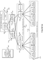
- leaf node E3 has only a single next hop to T4. (Note that one of next hops S1*-S4* may be used in the event that the link between E3 and T4 is down.) Similarly, leaf node E4 has only a single next hop to T4.
- leaf node E1 has four alternative next hops to T4 (e.g., via any one of spine nodes S1-S4).
- Next hop Sl is associated with at least one safe multipath next hop S2, S3, S4, next hop S2 is associated with a least one safe multipath next hop S1, S3, S4, next hop S3 is associated with at least one safe multipath next hop S1, S2, S4, and next hop S4 is associated with at least one safe multipath next hop S1, S2, S3.
- Leaf node E2 will have the same next hops (and the same safe multipath next hops) to T4.
- TOR node T1 will have two alternative next hops to T4 (e.g., via leaf node E1 or via leaf node E2). Further, next hop E1 is associated with safe multipath next hop E2, and next hop E2 is associated with safe multipath next hop E1. TOR node T2 will have the same next hops (and the same safe multipath next hops) to T4.
- the spine node S1 will have two alternative next hops to T4 (e.g., via leaf node E3 or via leaf node E4). Further, next hop E3 is associated with safe multipath next hop E4, and next hop E4 is associated with safe multipath next hop E3. Each of the spine nodes S2-S4 will have the same next hops (and the same safe multipath next hops) to T4. (Note that one of next hops E1* and E2* may be used in the event that both of the links between S1 and E3, and S1 and E4 are down. However, such double-link failures are not addressed with safe multipath next hop(s).)
- next hop to S1 will be excluded and the datagram destined for T4 will be forwarded via any one of S2-S4.
- a scheme such as random selection, round robin selection, etc.
- a selection scheme with an even distribution i.e., in which available next hops are equally likely to be selected may be used.
- Example implementations consistent with the present description permit node E3 to install an alternative path, via any one of spine nodes S1-S4, for datagrams destined for T4.
- the alternative path next hops are denoted by an asterisk. This will enable E3 to perform fast reroute repair.
- node E3 may send a datagram destined for T4 back up to any one of the spine nodes S1-S4.
- the receiving spine node S1, S2, S3, or S4 will send the datagram right back to node E3, causing a routing micro-loop.
- the spine node S1, S2, S3, or S4 receiving the datagram determines the next hop to be node E3, since the next hop interface will be the same as the interface on which the datagram was received (Recall, e.g., 524 (YES) of Figure 5B .), the spine node will replace the next hop interface (to node E3) with a safe multipath next hop interface (e.g., to node E4). (See, e.g., Figure 7D .) Node E4 can then forward the packet to node T4, thereby bypassing the failed link f and avoiding a micro-loop.
- example methods consistent with the present description can be used to avoid micro-loops in a CLOS network, such as a CLOS network used in a data center.
- Figure 8 illustrates two data forwarding systems 810 and 820 coupled via communications links 830.
- the links may be physical links or "wireless" links.
- the data forwarding systems 810,820 may be nodes, such as routers for example, in a CLOS network. If the data forwarding systems 810,820 are example routers, each may include a control component (e.g., a routing engine) 814,824 and a forwarding component 812,822.
- Each data forwarding system 810,820 includes one or more interfaces 816,826 that terminate one or more communications links 830.
- the example method 500 described above may be implemented in the forwarding component 822 of device 820.
- the example method 500 described above may also be implemented, in part, by having the control component 824 of device 820 predetermine the safe next hop, the forwarding component 822 can identify the safe next hop interfaces without such predetermination by the control component 824.
- some example routers 900 include a control component (e.g., routing engine) 910 and a packet forwarding component (e.g., a packet forwarding engine) 990.
- a control component e.g., routing engine
- a packet forwarding component e.g., a packet forwarding engine
- the control component 910 may include an operating system (OS) kernel 920, routing protocol process(es) 930, label-based forwarding protocol process(es) 940, interface process(es) 950, user interface (e.g., command line interface) process(es) 960, and chassis process(es) 970, and may store routing table(s) 939, label forwarding information 945, and forwarding (e.g., route-based and/or label-based) table(s) 980.
- OS operating system
- the routing protocol process(es) 930 may support routing protocols such as the routing information protocol (“RIP") 931, the intermediate system-to-intermediate system protocol (“IS-IS") 932, the open shortest path first protocol (“OSPF”) 933, the enhanced interior gateway routing protocol (“EIGRP”) 934 and the border gateway protocol (“BGP”) 935, and the label-based forwarding protocol process(es) 940 may support protocols such as BGP 935, the label distribution protocol (“LDP”) 936 and the resource reservation protocol (“RSVP”) 937.
- One or more components may permit a user 965 to interact with the user interface process(es) 960.
- one or more components may permit an outside device to interact with one or more of the router protocol process(es) 930, the label-based forwarding protocol process(es) 940, the interface process(es) 950, and the chassis process(es) 970, via SNMP 985, and such processes may send information to an outside device via SNMP 985.
- the packet forwarding component 990 may include a microkernel 992, interface process(es) 993, distributed ASICs 994, chassis process(es) 995 and forwarding (e.g., route-based and/or label-based) table(s) 996.
- the control component 910 handles tasks such as performing routing protocols, performing label-based forwarding protocols, control packet processing, etc., which frees the packet forwarding component 990 to forward received packets quickly. That is, received control packets (e.g., routing protocol packets and/or label-based forwarding protocol packets) are not fully processed on the packet forwarding component 990 itself, but are passed to the control component 910, thereby reducing the amount of work that the packet forwarding component 990 has to do and freeing it to process packets to be forwarded efficiently.
- received control packets e.g., routing protocol packets and/or label-based forwarding protocol packets
- control component 910 is primarily responsible for running routing protocols and/or label-based forwarding protocols, maintaining the routing tables and/or label forwarding information, sending forwarding table updates to the packet forwarding component 990, and performing system management.
- the example control component 910 may handle routing protocol packets, provide a management interface, provide configuration management, perform accounting, and provide alarms.
- the processes 930, 940, 950, 960 and 970 may be modular, and may interact with the OS kernel 920. That is, nearly all of the processes communicate directly with the OS kernel 920. Using modular software that cleanly separates processes from each other isolates problems of a given process so that such problems do not impact other processes that may be running. Additionally, using modular software facilitates easier scaling.
- the example OS kernel 920 may incorporate an application programming interface ("API") system for external program calls and scripting capabilities.
- the control component 910 may be based on an Intel PCI platform running the OS from flash memory, with an alternate copy stored on the router's hard disk.
- the OS kernel 920 is layered on the Intel PCI platform and establishes communication between the Intel PCI platform and processes of the control component 910.
- the OS kernel 920 also ensures that the forwarding tables 996 in use by the packet forwarding component 990 are in sync with those 980 in the control component 910.
- the OS kernel 920 also provides a link between the control component 910 and the packet forwarding component 990.
- this process(es) 930 provides routing and routing control functions within the platform.
- the RIP 931, ISIS 932, OSPF 933 and EIGRP 934 (and BGP 935) protocols are provided.
- other routing protocols may be provided in addition, or alternatively.
- the label-based forwarding protocol process(es) 940 provides label forwarding and label control functions.
- the LDP 936 and RSVP 937 (and BGP 935) protocols are provided.
- other label-based forwarding protocols e.g., MPLS
- the routing table(s) 939 is produced by the routing protocol process(es) 930, while the label forwarding information 945 is produced by the label-based forwarding protocol process(es) 940.
- the interface process(es) 950 performs configuration of the physical interfaces (Recall, e.g., 816 and 826 of Figure 8 .) and encapsulation.
- the example control component 910 may provide several ways to manage the router. For example, it 910 may provide a user interface process(es) 960 which allows a system operator 965 to interact with the system through configuration, modifications, and monitoring.
- the SNMP 985 allows SNMP-capable systems to communicate with the router platform. This also allows the platform to provide necessary SNMP information to external agents.
- the SNMP 985 may permit management of the system from a network management station running software, such as Hewlett-Packard's Network Node Manager ("HP-NNM”), through a framework, such as Hewlett-Packard's OpenView. Accounting of packets (generally referred to as traffic statistics) may be performed by the control component 910, thereby avoiding slowing traffic forwarding by the packet forwarding component 990.
- HP-NNM Hewlett-Packard's Network Node Manager
- the example router 900 may provide for out-of-band management, RS-232 DB9 ports for serial console and remote management access, and tertiary storage using a removable PC card.
- a craft interface positioned on the front of the chassis provides an external view into the internal workings of the router. It can be used as a troubleshooting tool, a monitoring tool, or both.
- the craft interface may include LED indicators, alarm indicators, control component ports, and/or a display screen.
- the craft interface may provide interaction with a command line interface (“CLI”) 960 via a console port, an auxiliary port, and/or a management Ethernet port
- the packet forwarding component 990 is responsible for properly outputting received packets as quickly as possible. If there is no entry in the forwarding table for a given destination or a given label and the packet forwarding component 990 cannot perform forwarding by itself, it 990 may send the packets bound for that unknown destination off to the control component 910 for processing.
- the example packet forwarding component 990 is designed to perform Layer 2 and Layer 3 switching, route lookups, and rapid packet forwarding.
- the example packet forwarding component 990 has an embedded microkernel 992, interface process(es) 993, distributed ASICs 994, and chassis process(es) 995, and stores a forwarding (e.g., route-based and/or label-based) table(s) 996.
- the microkernel 992 interacts with the interface process(es) 993 and the chassis process(es) 995 to monitor and control these functions.
- the interface process(es) 992 has direct communication with the OS kernel 920 of the control component 910.
- This communication includes forwarding exception packets and control packets to the control component 910, receiving packets to be forwarded, receiving forwarding table updates, providing information about the health of the packet forwarding component 990 to the control component 910, and permitting configuration of the interfaces from the user interface (e.g., CLI) process(es) 960 of the control component 910.
- the stored forwarding table(s) 996 is static until a new one is received from the control component 910.
- the interface process(es) 993 uses the forwarding table(s) 996 to look up next-hop information.
- the interface process(es) 993 also has direct communication with the distributed ASICs 994.
- the chassis process(es) 995 may communicate directly with the microkernel 992 and with the distributed ASICs 994.
- the example method 500 consistent with the present disclosure may be implemented in the packet forwarding component 990.
- FIG. 10 is an example of how the ASICS may be distributed in the packet forwarding component 990 to divide the responsibility of packet forwarding.
- the ASICs of the packet forwarding component 990 may be distributed on physical interface cards ("PICs") 1010, flexible PIC concentrators ("FPCs") 1020, a midplane or backplane 1030, and a system control board(s) 1040 (for switching and/or forwarding).
- Switching fabric is also shown as a system switch board (“SSB”), or a switching and forwarding module (“SFM”) 1050.
- Each of the PICs 1010 includes one or more PIC I/O managers 1015.
- Each of the FPCs 1020 includes one or more I/O managers 1022, each with an associated memory 1024.
- the midplane/backplane 1030 includes buffer managers 1035a, 1035b.
- the system control board 1040 includes an internet processor 1042 and an instance of the forwarding table 1044 (Recall, e.g., 996 of Figure 9 ).
- the PICs 1010 contain the interface ports. Each PIC 1010 may be plugged into an FPC 1020. Each individual PIC 1010 may contain an ASIC that handles media-specific functions, such as framing or encapsulation. Some example PICs 1010 provide SDH/SONET, ATM, Gigabit Ethernet, Fast Ethernet, and/or DS3/E3 interface ports.
- An FPC 1020 can contain from one or more PICs 1010, and may carry the signals from the PICs 1010 to the midplane/backplane 1030 as shown in Figure 10 .
- the midplane/backplane 1030 holds the line cards.
- the line cards may connect into the midplane/backplane 1030 when inserted into the example router's chassis from the front.
- the control component (e.g., routing engine) 910 may plug into the rear of the midplane/backplane 1030 from the rear of the chassis.
- the midplane/backplane 1030 may carry electrical (or optical) signals and power to each line card and to the control component 910.
- the system control board 1040 may perform forwarding lookup. It 1040 may also communicate errors to the routing engine. Further, it 1040 may also monitor the condition of the router based on information it receives from sensors. If an abnormal condition is detected, the system control board 1040 may immediately notify the control component 910.
- each of the PICs 1010,910' contains at least one I/O manager ASIC 1015 responsible for media-specific tasks, such as encapsulation.
- the packets pass through these I/O ASICs on their way into and out of the router.
- the I/O manager ASIC 1015 on the PIC 1010,910' is responsible for managing the connection to the I/O manager ASIC 1022 on the FPC 1020,920', managing link-layer framing and creating the bit stream, performing cyclical redundancy checks (CRCs), and detecting link-layer errors and generating alarms, when appropriate.
- the FPC 1020 includes another I/O manager ASIC 1022.
- This ASIC 1022 takes the packets from the PICs 1010 and breaks them into (e.g., 64-byte) memory blocks.
- This FPC I/O manager ASIC 1022 sends the blocks to a first distributed buffer manager (DBM) 1035a', decoding encapsulation and protocol-specific information, counting packets and bytes for each logical circuit, verifying packet integrity, and applying class of service (CoS) rules to packets.
- DBM distributed buffer manager
- the example DBM ASIC 1035a' manages and writes packets to the shared memory 1024 across all FPCs 1020.
- the first DBM ASIC 1035a' also extracts information on the destination of the packet and passes this forwarding-related information to the Internet processor 1042/942'.
- the Internet processor 1042/942' performs the route lookup using the forwarding table 1044 and sends the information over to a second DBM ASIC 1035b'.
- the Internet processor ASIC 1042/942' also collects exception packets (i.e., those without a forwarding table entry) and sends them to the control component 910.
- the second DBM ASIC 1035b' then takes this information and the 64-byte blocks and forwards them to the I/O manager ASIC 1022 of the egress FPC 1020/920' (or multiple egress FPCs, in the case of multicast) for reassembly.
- the DBM ASICs 1035a' and 1035b' are responsible for managing the packet memory 1024 distributed across all FPCs 1020/920', extracting forwarding-related information from packets, and instructing the FPC where to forward packets.
- the I/O manager ASIC 1022 on the egress FPC 1020/920' may perform some value-added services.
- it can also apply class-of-service (CoS) rules. To do this, it may queue a pointer to the packet in one of the available queues, each having a share of link bandwidth, before applying the rules to the packet. Queuing can be based on various rules.
- the I/O manager ASIC 1022 on the egress FPC 1020/920' may be responsible for receiving the blocks from the second DBM ASIC 1035b', incrementing TTL values, queuing a pointer to the packet, if necessary, before applying CoS rules, re-encapsulating the blocks, and sending the encapsulated packets to the PIC I/O manager ASIC 1015.
- Figure 12 is a flow diagram of an example method 1200 for providing packet forwarding in the example router.
- the main acts of the method 1200 are triggered when a packet is received on an ingress (incoming) port or interface.
- Event 1210 The types of checksum and frame checks that are required by the type of medium it serves are performed and the packet is output, as a serial bit stream.
- the packet is then decapsulated and parsed into (e.g., 64-byte) blocks.
- the packets are written to buffer memory and the forwarding information is passed on the Internet processor.
- the passed forwarding information is then used to lookup a route in the forwarding table.
- Block 1250 (Recall, e.g., Figures 7A-7D .) Note that the forwarding table can typically handle unicast packets that do not have options (e.g., accounting) set, and multicast packets for which it already has a cached entry.
- options e.g., accounting
- the packet forwarding component finds the next hop and egress interface, and the packet is forwarded (or queued for forwarding) to the next hop via the egress interface (Block 1270) before the method 1200 is left (Node 1290) Otherwise, if these conditions are not met (NO branch of Decision 1260), the forwarding information is sent to the control component 910 for advanced forwarding resolution (Block 1280) before the method 1200 is left (Node 1290).
- the packet may be queued.
- a pointer to the packet may be queued.
- the packet itself may remain in the shared memory. Thus, all queuing decisions and CoS rules may be applied in the absence of the actual packet.
- the I/O manager ASIC 1022 may send a request for the packet to the second DBM ASIC 1035b.
- the DBM ASIC 1035 reads the blocks from shared memory and sends them to the I/O manager ASIC 1022 on the FPC 1020, which then serializes the bits and sends them to the media-specific ASIC of the egress interface.
- the I/O manager ASIC 1015 on the egress PIC 1010 may apply the physical-layer framing, perform the CRC, and send the bit stream out over the link.
- the system control board 1040 handles nearly all exception packets.
- the system control board 1040 may pass exception packets to the control component 910.
- the forwarding tables may include information such as that described with reference to Figures 7A-7D .
- embodiments consistent with the present disclosure may be implemented on the example routers of Figure 8 or 9
- embodiments consistent with the present disclosure may be implemented on communications network nodes (e.g., routers, switches, etc.) having different architectures. More generally, embodiments consistent with the present disclosure may be implemented on an example system 1300 as illustrated on Figure 13 .
- Figure 13 is a block diagram of an example machine 1300 that may perform one or more of the methods described, and/or store information used and/or generated by such methods.
- the example machine 1300 includes one or more processors 1310, one or more input/output interface units 1330, one or more storage devices 1320, and one or more system buses and/or networks 1340 for facilitating the communication of information among the coupled elements.
- One or more input devices 1332 and one or more output devices 1334 may be coupled with the one or more input/output interfaces 1330.
- the one or more processors 1310 may execute machine-executable instructions (e.g., C or C++ running on the Linux operating system widely available from a number of vendors) to effect one or more aspects of the present disclosure.
- machine-executable instructions e.g., C or C++ running on the Linux operating system widely available from a number of vendors
- At least a portion of the machine executable instructions may be stored (temporarily or more permanently) on the one or more storage devices 1320 and/or may be received from an external source via one or more input interface units 1330.
- the machine executable instructions may be stored as various software modules, each module performing one or more operations. Functional software modules are examples of components which may be used in the apparatus described.
- the processors 1310 may be one or more microprocessors and/or ASICs.
- the bus 1340 may include a system bus.
- the storage devices 1320 may include system memory, such as read only memory (ROM) and/or random access memory (RAM).
- the storage devices 1320 may also include a hard disk drive for reading from and writing to a hard disk, a magnetic disk drive for reading from or writing to a (e.g., removable) magnetic disk, an optical disk drive for reading from or writing to a removable (magneto-) optical disk such as a compact disk or other (magneto-) optical media, or solid-state non-volatile storage.
- Some example embodiments consistent with the present disclosure may also be provided as a computer-readable medium for storing the computer-executable instructions.
- the computer-readable medium may be non-transitory and may include, but is not limited to, flash memory, optical disks, CD-ROMs, DVD ROMs, RAMs, EPROMs, EEPROMs, magnetic or optical cards or any other type of computer-readable media suitable for storing electronic instructions.
- example embodiments consistent with the present disclosure may be downloaded as a computer program which may be transferred from a remote computer (e.g., a server) to a requesting computer (e.g., a client) by way of a communication link (e.g., a modem or network connection) and stored on a non-transitory storage medium.
- the computer-readable medium may also be referred to as a processor-readable medium. Additionally or alternatively the computer-readable medium may include transient media such as carrier signals and transmission media.
- Example embodiments consistent with the present disclosure might be implemented in hardware, such as one or more field programmable gate arrays ("FPGA"s), one or more integrated circuits such as ASICs, one or more network processors, etc.
- FPGA field programmable gate arrays
- ASIC application specific integrated circuits
- network processors etc.
- embodiments consistent with the present disclosure might be implemented as stored program instructions executed by a processor.
- Such hardware and/or software might be provided in an addressed data (e.g., packet, cell, etc.) forwarding device (e.g., a switch, a router, etc.), a laptop computer, desktop computer, a tablet computer, a mobile phone, or any device that has computing and networking capabilities.
- nodes may represent other types of devices capable of performing the foregoing node operations.
- the act of determining a next hop and an egress interface may include performing a single lookup using the destination information and the interface on which the datagram was received to select the egress interface and a next hop (e.g., in a single lookup operation).
- this problem may be solved by(a) receiving, on an interface a node of the CLOS network, a datagram, the datagram including destination information; (b) looking up, using the destination information of the received datagram and stored forwarding information, a next hop egress interface on the node; (c) determining whether or not the next hop egress interface on the node is the same as the interface on which the datagram was received; and (d) responsive to a determination that the next hop egress interface on the node is the same as the interface on which the datagram was received, (1) replacing the next hop egress interface with a safe multipath next hop egress interface, and (2) forwarding the datagram via the safe multipath next hop egress interface, and otherwise, responsive to a determination that the next hop egress interface on the node is not the same at the interface on which the datagram was received, simply forwarding the datagram via the next hop egress interface.
- example methods and apparatus consistent with the present disclosure reduce or eliminate routing micro-loops in networks having a CLOS topology, such as data center CLOS networks employing the exterior border gateway protocol (eBGP) for example.
- eBGP exterior border gateway protocol
Landscapes
- Engineering & Computer Science (AREA)
- Computer Networks & Wireless Communication (AREA)
- Signal Processing (AREA)
- Data Exchanges In Wide-Area Networks (AREA)
Applications Claiming Priority (1)
| Application Number | Priority Date | Filing Date | Title |
|---|---|---|---|
| US15/990,560 US10574566B2 (en) | 2018-05-25 | 2018-05-25 | Reducing or eliminating routing microloops in networks having a CLOS topology, such as data center CLOS networks employing the exterior border gateway protocol (EBGP) for example |
Publications (2)
| Publication Number | Publication Date |
|---|---|
| EP3573293A1 true EP3573293A1 (de) | 2019-11-27 |
| EP3573293B1 EP3573293B1 (de) | 2023-10-25 |
Family
ID=65657318
Family Applications (1)
| Application Number | Title | Priority Date | Filing Date |
|---|---|---|---|
| EP19160188.9A Active EP3573293B1 (de) | 2018-05-25 | 2019-03-01 | Reduzieren oder eliminieren von routing-mikroschleifen in netzwerken mit clos-topologie wie etwa datencenter-clos-netzwerke unter verwendung des aussengrenzen-gateway-protokolls |
Country Status (3)
| Country | Link |
|---|---|
| US (1) | US10574566B2 (de) |
| EP (1) | EP3573293B1 (de) |
| CN (1) | CN110535769B (de) |
Families Citing this family (25)
| Publication number | Priority date | Publication date | Assignee | Title |
|---|---|---|---|---|
| US10243848B2 (en) | 2015-06-27 | 2019-03-26 | Nicira, Inc. | Provisioning logical entities in a multi-datacenter environment |
| US20200007382A1 (en) * | 2018-06-28 | 2020-01-02 | Microsoft Technology Licensing, Llc | Accelerated convergence in networks with clos topologies |
| TWI821373B (zh) | 2018-08-23 | 2023-11-11 | 美商阿爾克斯股份有限公司 | 網路運算環境中的第一跳轉閘道的冗餘機制系統 |
| CN111526113B (zh) * | 2019-02-02 | 2023-05-30 | 中兴通讯股份有限公司 | 协议处理方法及装置、存储介质 |
| US11368394B2 (en) * | 2019-04-26 | 2022-06-21 | Hewlett Packard Enterprise Development Lp | Using labels in a virtualized device environment |
| US10924435B2 (en) * | 2019-05-15 | 2021-02-16 | Dell Products, L.P. | System and method for port reduction using multiple chassis link aggregation group for stacked devices |
| US11050679B1 (en) * | 2019-06-28 | 2021-06-29 | Juniper Networks, Inc. | Defining non-forwarding adjacencies in bipartite networks, such as Clos newtorks, having a level 2 backbone and level 1 nodes |
| US11496391B1 (en) * | 2019-06-28 | 2022-11-08 | Juniper Networks, Inc. | Defining non-forwarding adjacencies in bipartite networks, such as Clos networks, having a level 2 backbone and level 1 nodes |
| US11153420B2 (en) * | 2019-10-18 | 2021-10-19 | Arista Networks, Inc. | Neighbor equivalence groups |
| US11438238B2 (en) | 2020-04-06 | 2022-09-06 | Vmware, Inc. | User interface for accessing multi-site logical network |
| US11777793B2 (en) | 2020-04-06 | 2023-10-03 | Vmware, Inc. | Location criteria for security groups |
| US11528214B2 (en) | 2020-04-06 | 2022-12-13 | Vmware, Inc. | Logical router implementation across multiple datacenters |
| US11088902B1 (en) | 2020-04-06 | 2021-08-10 | Vmware, Inc. | Synchronization of logical network state between global and local managers |
| US11799726B2 (en) | 2020-04-06 | 2023-10-24 | Vmware, Inc. | Multi-site security groups |
| CN113810275B (zh) * | 2020-06-17 | 2023-08-04 | 华为技术有限公司 | 发送报文的方法及设备 |
| US11343227B2 (en) | 2020-09-28 | 2022-05-24 | Vmware, Inc. | Application deployment in multi-site virtualization infrastructure |
| CN115086222B (zh) * | 2021-03-15 | 2023-06-20 | 中国电信股份有限公司 | 跨自治域通告方法、自治系统边界路由器和通信系统 |
| US11863350B2 (en) * | 2021-09-09 | 2024-01-02 | Ciena Corporation | Fast convergence of E-Tree with a dual homed root node |
| US12107722B2 (en) | 2022-07-20 | 2024-10-01 | VMware LLC | Sharing network manager between multiple tenants |
| US12587466B2 (en) | 2022-11-09 | 2026-03-24 | Pensando Systems Inc. | Active-standby switchover in border gateway protocol (BGP) network using graceful attract community |
| US12184521B2 (en) | 2023-02-23 | 2024-12-31 | VMware LLC | Framework for providing health status data |
| US12126528B2 (en) * | 2023-03-24 | 2024-10-22 | Nokia Solutions And Networks Oy | Egress rerouting of packets at a communication device |
| CN117081988A (zh) * | 2023-08-25 | 2023-11-17 | 新华三技术有限公司 | 通信方法及装置 |
| CN117278499B (zh) * | 2023-11-16 | 2024-03-01 | 苏州元脑智能科技有限公司 | 一种网络链路创建方法、装置、设备及存储介质 |
| CN121396798A (zh) * | 2024-07-22 | 2026-01-23 | 华为技术有限公司 | 网络系统、流量转发方法、装置、设备、芯片及存储介质 |
Citations (2)
| Publication number | Priority date | Publication date | Assignee | Title |
|---|---|---|---|---|
| US20130170504A1 (en) * | 2010-09-22 | 2013-07-04 | Fujitsu Limited | Routing method and node equipment |
| US20160105354A1 (en) * | 2014-10-08 | 2016-04-14 | Dell Products L.P. | Multicast routing via non-minimal paths |
Family Cites Families (9)
| Publication number | Priority date | Publication date | Assignee | Title |
|---|---|---|---|---|
| US8098574B2 (en) * | 2008-08-26 | 2012-01-17 | Fulcrum Microsystems, Inc. | Global ports in multi-switch systems |
| US9497039B2 (en) * | 2009-05-28 | 2016-11-15 | Microsoft Technology Licensing, Llc | Agile data center network architecture |
| CN102195883A (zh) * | 2011-05-23 | 2011-09-21 | 北京星网锐捷网络技术有限公司 | 组播路由确定方法、组播报文转发方法及装置 |
| US9350654B1 (en) * | 2013-07-18 | 2016-05-24 | Juniper Networks, Inc. | Microloop protection for multi-protocol label switching paths |
| EP3605971B1 (de) * | 2013-11-05 | 2021-10-13 | Cisco Technology, Inc. | Netzwerk-fabric-überlagerung |
| US10951522B2 (en) * | 2013-11-05 | 2021-03-16 | Cisco Technology, Inc. | IP-based forwarding of bridged and routed IP packets and unicast ARP |
| US9838246B1 (en) * | 2014-09-30 | 2017-12-05 | Juniper Networks, Inc. | Micro-loop prevention using source packet routing |
| US9419918B2 (en) * | 2014-11-07 | 2016-08-16 | Futurewei Technologies, Inc. | Non-transparent bridge method and apparatus for configuring high-dimensional PCI-express networks |
| US11777853B2 (en) * | 2016-04-12 | 2023-10-03 | Nicira, Inc. | Congestion-aware load balancing in data center networks |
-
2018
- 2018-05-25 US US15/990,560 patent/US10574566B2/en active Active
-
2019
- 2019-02-28 CN CN201910152805.0A patent/CN110535769B/zh active Active
- 2019-03-01 EP EP19160188.9A patent/EP3573293B1/de active Active
Patent Citations (2)
| Publication number | Priority date | Publication date | Assignee | Title |
|---|---|---|---|---|
| US20130170504A1 (en) * | 2010-09-22 | 2013-07-04 | Fujitsu Limited | Routing method and node equipment |
| US20160105354A1 (en) * | 2014-10-08 | 2016-04-14 | Dell Products L.P. | Multicast routing via non-minimal paths |
Non-Patent Citations (1)
| Title |
|---|
| YONG LIAO ET AL: "DPillar: Scalable Dual-Port Server Interconnection for Data Center Networks", COMPUTER COMMUNICATIONS AND NETWORKS (ICCCN), 2010 PROCEEDINGS OF 19TH INTERNATIONAL CONFERENCE ON, IEEE, PISCATAWAY, NJ, USA, 2 August 2010 (2010-08-02), pages 1 - 6, XP031744423, ISBN: 978-1-4244-7114-0 * |
Also Published As
| Publication number | Publication date |
|---|---|
| US10574566B2 (en) | 2020-02-25 |
| US20190363975A1 (en) | 2019-11-28 |
| CN110535769A (zh) | 2019-12-03 |
| EP3573293B1 (de) | 2023-10-25 |
| CN110535769B (zh) | 2022-02-25 |
Similar Documents
| Publication | Publication Date | Title |
|---|---|---|
| EP3573293B1 (de) | Reduzieren oder eliminieren von routing-mikroschleifen in netzwerken mit clos-topologie wie etwa datencenter-clos-netzwerke unter verwendung des aussengrenzen-gateway-protokolls | |
| US11546246B2 (en) | Minimizing or reducing traffic loss when an external border gateway protocol (eBGP) peer goes down | |
| US11057243B2 (en) | Aliasing behavior for traffic to multihomed sites in ethernet virtual private network (EVPN) networks | |
| US20210250270A1 (en) | Path monitoring system (pms) controller or ingress node based multiprotocal label switching (mpls) ping and traceroute in inter-autonomous system (as) segment routing (sr) networks | |
| US11349735B2 (en) | Faster fault-detection mechanism, for example using bidirectional forwarding detection (BFD), on network nodes and/or hosts multihomed using a link aggregation group (LAG) | |
| US11496391B1 (en) | Defining non-forwarding adjacencies in bipartite networks, such as Clos networks, having a level 2 backbone and level 1 nodes | |
| US9444768B1 (en) | Multi-router system having shared network interfaces | |
| EP3799354B1 (de) | Synchronisierung der multicast-router-fähigkeit einer protocol independent multicast (pim)-multihome-vorrichtung mit virtuellem privaten ethernet-netzwerk (evpn) | |
| US10594592B1 (en) | Controlling advertisements, such as Border Gateway Protocol (“BGP”) updates, of multiple paths for a given address prefix | |
| US12184532B1 (en) | Using anycast as an abstract next hop (ANH) to reduce information related to border gateway protocol (BGP) next hops received by autonomous system border routers (ASBRs) and/or to improve BGP path convergence | |
| US11050679B1 (en) | Defining non-forwarding adjacencies in bipartite networks, such as Clos newtorks, having a level 2 backbone and level 1 nodes | |
| US11336569B2 (en) | Ping and traceroute in inter-autonomous system (AS) segment routing (SR) networks without requiring headend router or path monitoring system (PMS) controller knowledge of topology outside of origin as | |
| US11057295B1 (en) | Loop avoidance and egress link protection with ethernet virtual private network (EVPN) fast reroute (FRR) | |
| US12407611B2 (en) | Reducing convergence time and/or avoiding split-brain in multi-homed ethernet segment deployments, such as esi-lag deployments | |
| US12425331B2 (en) | Avoiding loops by preventing further fast reroute (FRR) after an earlier FRR | |
| US10728137B1 (en) | Protocol independent multicast (“PIM”) fault tolerant designated router (“DR”) election | |
| US12375398B2 (en) | Bandwidth advertisement for floor reflector (FR) traffic engineering (TE) links | |
| CN113381930B (zh) | 用于虚拟路由器冗余的组负载均衡 | |
| US20260032093A1 (en) | Methods for configuring flexible mac group to packet forwarding engine (pfe) connections, and devices with flexible mac group to pfe connections |
Legal Events
| Date | Code | Title | Description |
|---|---|---|---|
| PUAI | Public reference made under article 153(3) epc to a published international application that has entered the european phase |
Free format text: ORIGINAL CODE: 0009012 |
|
| STAA | Information on the status of an ep patent application or granted ep patent |
Free format text: STATUS: THE APPLICATION HAS BEEN PUBLISHED |
|
| AK | Designated contracting states |
Kind code of ref document: A1 Designated state(s): AL AT BE BG CH CY CZ DE DK EE ES FI FR GB GR HR HU IE IS IT LI LT LU LV MC MK MT NL NO PL PT RO RS SE SI SK SM TR |
|
| AX | Request for extension of the european patent |
Extension state: BA ME |
|
| STAA | Information on the status of an ep patent application or granted ep patent |
Free format text: STATUS: REQUEST FOR EXAMINATION WAS MADE |
|
| 17P | Request for examination filed |
Effective date: 20200331 |
|
| RBV | Designated contracting states (corrected) |
Designated state(s): AL AT BE BG CH CY CZ DE DK EE ES FI FR GB GR HR HU IE IS IT LI LT LU LV MC MK MT NL NO PL PT RO RS SE SI SK SM TR |
|
| STAA | Information on the status of an ep patent application or granted ep patent |
Free format text: STATUS: EXAMINATION IS IN PROGRESS |
|
| 17Q | First examination report despatched |
Effective date: 20200619 |
|
| REG | Reference to a national code |
Ref legal event code: R079 Ipc: H04L0045180000 Ref country code: DE Ref legal event code: R079 Ref document number: 602019039895 Country of ref document: DE Free format text: PREVIOUS MAIN CLASS: H04L0012707000 Ipc: H04L0045180000 |
|
| GRAP | Despatch of communication of intention to grant a patent |
Free format text: ORIGINAL CODE: EPIDOSNIGR1 |
|
| STAA | Information on the status of an ep patent application or granted ep patent |
Free format text: STATUS: GRANT OF PATENT IS INTENDED |
|
| RIC1 | Information provided on ipc code assigned before grant |
Ipc: H04L 45/00 20220101ALI20230418BHEP Ipc: H04L 45/18 20220101AFI20230418BHEP |
|
| INTG | Intention to grant announced |
Effective date: 20230524 |
|
| GRAS | Grant fee paid |
Free format text: ORIGINAL CODE: EPIDOSNIGR3 |
|
| GRAA | (expected) grant |
Free format text: ORIGINAL CODE: 0009210 |
|
| STAA | Information on the status of an ep patent application or granted ep patent |
Free format text: STATUS: THE PATENT HAS BEEN GRANTED |
|
| AK | Designated contracting states |
Kind code of ref document: B1 Designated state(s): AL AT BE BG CH CY CZ DE DK EE ES FI FR GB GR HR HU IE IS IT LI LT LU LV MC MK MT NL NO PL PT RO RS SE SI SK SM TR |
|
| REG | Reference to a national code |
Ref country code: GB Ref legal event code: FG4D |
|
| REG | Reference to a national code |
Ref country code: CH Ref legal event code: EP |
|
| P01 | Opt-out of the competence of the unified patent court (upc) registered |
Effective date: 20231010 |
|
| REG | Reference to a national code |
Ref country code: DE Ref legal event code: R096 Ref document number: 602019039895 Country of ref document: DE |
|
| REG | Reference to a national code |
Ref country code: IE Ref legal event code: FG4D |
|
| REG | Reference to a national code |
Ref country code: LT Ref legal event code: MG9D |
|
| REG | Reference to a national code |
Ref country code: NL Ref legal event code: MP Effective date: 20231025 |
|
| REG | Reference to a national code |
Ref country code: AT Ref legal event code: MK05 Ref document number: 1625835 Country of ref document: AT Kind code of ref document: T Effective date: 20231025 |
|
| PG25 | Lapsed in a contracting state [announced via postgrant information from national office to epo] |
Ref country code: NL Free format text: LAPSE BECAUSE OF FAILURE TO SUBMIT A TRANSLATION OF THE DESCRIPTION OR TO PAY THE FEE WITHIN THE PRESCRIBED TIME-LIMIT Effective date: 20231025 |
|
| PG25 | Lapsed in a contracting state [announced via postgrant information from national office to epo] |
Ref country code: GR Free format text: LAPSE BECAUSE OF FAILURE TO SUBMIT A TRANSLATION OF THE DESCRIPTION OR TO PAY THE FEE WITHIN THE PRESCRIBED TIME-LIMIT Effective date: 20240126 |
|
| PG25 | Lapsed in a contracting state [announced via postgrant information from national office to epo] |
Ref country code: IS Free format text: LAPSE BECAUSE OF FAILURE TO SUBMIT A TRANSLATION OF THE DESCRIPTION OR TO PAY THE FEE WITHIN THE PRESCRIBED TIME-LIMIT Effective date: 20240225 |
|
| PG25 | Lapsed in a contracting state [announced via postgrant information from national office to epo] |
Ref country code: LT Free format text: LAPSE BECAUSE OF FAILURE TO SUBMIT A TRANSLATION OF THE DESCRIPTION OR TO PAY THE FEE WITHIN THE PRESCRIBED TIME-LIMIT Effective date: 20231025 |
|
| PG25 | Lapsed in a contracting state [announced via postgrant information from national office to epo] |
Ref country code: AT Free format text: LAPSE BECAUSE OF FAILURE TO SUBMIT A TRANSLATION OF THE DESCRIPTION OR TO PAY THE FEE WITHIN THE PRESCRIBED TIME-LIMIT Effective date: 20231025 |
|
| PG25 | Lapsed in a contracting state [announced via postgrant information from national office to epo] |
Ref country code: ES Free format text: LAPSE BECAUSE OF FAILURE TO SUBMIT A TRANSLATION OF THE DESCRIPTION OR TO PAY THE FEE WITHIN THE PRESCRIBED TIME-LIMIT Effective date: 20231025 |
|
| PG25 | Lapsed in a contracting state [announced via postgrant information from national office to epo] |
Ref country code: LT Free format text: LAPSE BECAUSE OF FAILURE TO SUBMIT A TRANSLATION OF THE DESCRIPTION OR TO PAY THE FEE WITHIN THE PRESCRIBED TIME-LIMIT Effective date: 20231025 Ref country code: IS Free format text: LAPSE BECAUSE OF FAILURE TO SUBMIT A TRANSLATION OF THE DESCRIPTION OR TO PAY THE FEE WITHIN THE PRESCRIBED TIME-LIMIT Effective date: 20240225 Ref country code: GR Free format text: LAPSE BECAUSE OF FAILURE TO SUBMIT A TRANSLATION OF THE DESCRIPTION OR TO PAY THE FEE WITHIN THE PRESCRIBED TIME-LIMIT Effective date: 20240126 Ref country code: ES Free format text: LAPSE BECAUSE OF FAILURE TO SUBMIT A TRANSLATION OF THE DESCRIPTION OR TO PAY THE FEE WITHIN THE PRESCRIBED TIME-LIMIT Effective date: 20231025 Ref country code: BG Free format text: LAPSE BECAUSE OF FAILURE TO SUBMIT A TRANSLATION OF THE DESCRIPTION OR TO PAY THE FEE WITHIN THE PRESCRIBED TIME-LIMIT Effective date: 20240125 Ref country code: AT Free format text: LAPSE BECAUSE OF FAILURE TO SUBMIT A TRANSLATION OF THE DESCRIPTION OR TO PAY THE FEE WITHIN THE PRESCRIBED TIME-LIMIT Effective date: 20231025 Ref country code: PT Free format text: LAPSE BECAUSE OF FAILURE TO SUBMIT A TRANSLATION OF THE DESCRIPTION OR TO PAY THE FEE WITHIN THE PRESCRIBED TIME-LIMIT Effective date: 20240226 |
|
| PG25 | Lapsed in a contracting state [announced via postgrant information from national office to epo] |
Ref country code: SE Free format text: LAPSE BECAUSE OF FAILURE TO SUBMIT A TRANSLATION OF THE DESCRIPTION OR TO PAY THE FEE WITHIN THE PRESCRIBED TIME-LIMIT Effective date: 20231025 Ref country code: RS Free format text: LAPSE BECAUSE OF FAILURE TO SUBMIT A TRANSLATION OF THE DESCRIPTION OR TO PAY THE FEE WITHIN THE PRESCRIBED TIME-LIMIT Effective date: 20231025 Ref country code: PL Free format text: LAPSE BECAUSE OF FAILURE TO SUBMIT A TRANSLATION OF THE DESCRIPTION OR TO PAY THE FEE WITHIN THE PRESCRIBED TIME-LIMIT Effective date: 20231025 Ref country code: NO Free format text: LAPSE BECAUSE OF FAILURE TO SUBMIT A TRANSLATION OF THE DESCRIPTION OR TO PAY THE FEE WITHIN THE PRESCRIBED TIME-LIMIT Effective date: 20240125 Ref country code: LV Free format text: LAPSE BECAUSE OF FAILURE TO SUBMIT A TRANSLATION OF THE DESCRIPTION OR TO PAY THE FEE WITHIN THE PRESCRIBED TIME-LIMIT Effective date: 20231025 Ref country code: HR Free format text: LAPSE BECAUSE OF FAILURE TO SUBMIT A TRANSLATION OF THE DESCRIPTION OR TO PAY THE FEE WITHIN THE PRESCRIBED TIME-LIMIT Effective date: 20231025 |
|
| PG25 | Lapsed in a contracting state [announced via postgrant information from national office to epo] |
Ref country code: DK Free format text: LAPSE BECAUSE OF FAILURE TO SUBMIT A TRANSLATION OF THE DESCRIPTION OR TO PAY THE FEE WITHIN THE PRESCRIBED TIME-LIMIT Effective date: 20231025 |
|
| PG25 | Lapsed in a contracting state [announced via postgrant information from national office to epo] |
Ref country code: CZ Free format text: LAPSE BECAUSE OF FAILURE TO SUBMIT A TRANSLATION OF THE DESCRIPTION OR TO PAY THE FEE WITHIN THE PRESCRIBED TIME-LIMIT Effective date: 20231025 |
|
| REG | Reference to a national code |
Ref country code: DE Ref legal event code: R097 Ref document number: 602019039895 Country of ref document: DE |
|
| PG25 | Lapsed in a contracting state [announced via postgrant information from national office to epo] |
Ref country code: SK Free format text: LAPSE BECAUSE OF FAILURE TO SUBMIT A TRANSLATION OF THE DESCRIPTION OR TO PAY THE FEE WITHIN THE PRESCRIBED TIME-LIMIT Effective date: 20231025 |
|
| PG25 | Lapsed in a contracting state [announced via postgrant information from national office to epo] |
Ref country code: SM Free format text: LAPSE BECAUSE OF FAILURE TO SUBMIT A TRANSLATION OF THE DESCRIPTION OR TO PAY THE FEE WITHIN THE PRESCRIBED TIME-LIMIT Effective date: 20231025 Ref country code: SK Free format text: LAPSE BECAUSE OF FAILURE TO SUBMIT A TRANSLATION OF THE DESCRIPTION OR TO PAY THE FEE WITHIN THE PRESCRIBED TIME-LIMIT Effective date: 20231025 Ref country code: RO Free format text: LAPSE BECAUSE OF FAILURE TO SUBMIT A TRANSLATION OF THE DESCRIPTION OR TO PAY THE FEE WITHIN THE PRESCRIBED TIME-LIMIT Effective date: 20231025 Ref country code: IT Free format text: LAPSE BECAUSE OF FAILURE TO SUBMIT A TRANSLATION OF THE DESCRIPTION OR TO PAY THE FEE WITHIN THE PRESCRIBED TIME-LIMIT Effective date: 20231025 Ref country code: EE Free format text: LAPSE BECAUSE OF FAILURE TO SUBMIT A TRANSLATION OF THE DESCRIPTION OR TO PAY THE FEE WITHIN THE PRESCRIBED TIME-LIMIT Effective date: 20231025 Ref country code: DK Free format text: LAPSE BECAUSE OF FAILURE TO SUBMIT A TRANSLATION OF THE DESCRIPTION OR TO PAY THE FEE WITHIN THE PRESCRIBED TIME-LIMIT Effective date: 20231025 Ref country code: CZ Free format text: LAPSE BECAUSE OF FAILURE TO SUBMIT A TRANSLATION OF THE DESCRIPTION OR TO PAY THE FEE WITHIN THE PRESCRIBED TIME-LIMIT Effective date: 20231025 |
|
| PLBE | No opposition filed within time limit |
Free format text: ORIGINAL CODE: 0009261 |
|
| STAA | Information on the status of an ep patent application or granted ep patent |
Free format text: STATUS: NO OPPOSITION FILED WITHIN TIME LIMIT |
|
| 26N | No opposition filed |
Effective date: 20240726 |
|
| PG25 | Lapsed in a contracting state [announced via postgrant information from national office to epo] |
Ref country code: SI Free format text: LAPSE BECAUSE OF FAILURE TO SUBMIT A TRANSLATION OF THE DESCRIPTION OR TO PAY THE FEE WITHIN THE PRESCRIBED TIME-LIMIT Effective date: 20231025 |
|
| PG25 | Lapsed in a contracting state [announced via postgrant information from national office to epo] |
Ref country code: SI Free format text: LAPSE BECAUSE OF FAILURE TO SUBMIT A TRANSLATION OF THE DESCRIPTION OR TO PAY THE FEE WITHIN THE PRESCRIBED TIME-LIMIT Effective date: 20231025 |
|
| REG | Reference to a national code |
Ref country code: CH Ref legal event code: PL |
|
| PG25 | Lapsed in a contracting state [announced via postgrant information from national office to epo] |
Ref country code: LU Free format text: LAPSE BECAUSE OF NON-PAYMENT OF DUE FEES Effective date: 20240301 |
|
| PG25 | Lapsed in a contracting state [announced via postgrant information from national office to epo] |
Ref country code: MC Free format text: LAPSE BECAUSE OF FAILURE TO SUBMIT A TRANSLATION OF THE DESCRIPTION OR TO PAY THE FEE WITHIN THE PRESCRIBED TIME-LIMIT Effective date: 20231025 |
|
| PG25 | Lapsed in a contracting state [announced via postgrant information from national office to epo] |
Ref country code: MC Free format text: LAPSE BECAUSE OF FAILURE TO SUBMIT A TRANSLATION OF THE DESCRIPTION OR TO PAY THE FEE WITHIN THE PRESCRIBED TIME-LIMIT Effective date: 20231025 Ref country code: LU Free format text: LAPSE BECAUSE OF NON-PAYMENT OF DUE FEES Effective date: 20240301 |
|
| REG | Reference to a national code |
Ref country code: BE Ref legal event code: MM Effective date: 20240331 |
|
| PG25 | Lapsed in a contracting state [announced via postgrant information from national office to epo] |
Ref country code: BE Free format text: LAPSE BECAUSE OF NON-PAYMENT OF DUE FEES Effective date: 20240331 |
|
| PG25 | Lapsed in a contracting state [announced via postgrant information from national office to epo] |
Ref country code: IE Free format text: LAPSE BECAUSE OF NON-PAYMENT OF DUE FEES Effective date: 20240301 |
|
| PG25 | Lapsed in a contracting state [announced via postgrant information from national office to epo] |
Ref country code: IE Free format text: LAPSE BECAUSE OF NON-PAYMENT OF DUE FEES Effective date: 20240301 Ref country code: BE Free format text: LAPSE BECAUSE OF NON-PAYMENT OF DUE FEES Effective date: 20240331 Ref country code: CH Free format text: LAPSE BECAUSE OF NON-PAYMENT OF DUE FEES Effective date: 20240331 |
|
| PG25 | Lapsed in a contracting state [announced via postgrant information from national office to epo] |
Ref country code: CY Free format text: LAPSE BECAUSE OF FAILURE TO SUBMIT A TRANSLATION OF THE DESCRIPTION OR TO PAY THE FEE WITHIN THE PRESCRIBED TIME-LIMIT; INVALID AB INITIO Effective date: 20190301 |
|
| PG25 | Lapsed in a contracting state [announced via postgrant information from national office to epo] |
Ref country code: HU Free format text: LAPSE BECAUSE OF FAILURE TO SUBMIT A TRANSLATION OF THE DESCRIPTION OR TO PAY THE FEE WITHIN THE PRESCRIBED TIME-LIMIT; INVALID AB INITIO Effective date: 20190301 |
|
| PG25 | Lapsed in a contracting state [announced via postgrant information from national office to epo] |
Ref country code: FI Free format text: LAPSE BECAUSE OF FAILURE TO SUBMIT A TRANSLATION OF THE DESCRIPTION OR TO PAY THE FEE WITHIN THE PRESCRIBED TIME-LIMIT Effective date: 20231025 |
|
| PG25 | Lapsed in a contracting state [announced via postgrant information from national office to epo] |
Ref country code: TR Free format text: LAPSE BECAUSE OF FAILURE TO SUBMIT A TRANSLATION OF THE DESCRIPTION OR TO PAY THE FEE WITHIN THE PRESCRIBED TIME-LIMIT Effective date: 20231025 |
|
| PGFP | Annual fee paid to national office [announced via postgrant information from national office to epo] |
Ref country code: GB Payment date: 20260219 Year of fee payment: 8 |
|
| PGFP | Annual fee paid to national office [announced via postgrant information from national office to epo] |
Ref country code: DE Payment date: 20260219 Year of fee payment: 8 |
|
| PGFP | Annual fee paid to national office [announced via postgrant information from national office to epo] |
Ref country code: FR Payment date: 20260219 Year of fee payment: 8 |