EP3573207A1 - Electrical power system including energy storage modules and shared system controller - Google Patents
Electrical power system including energy storage modules and shared system controller Download PDFInfo
- Publication number
- EP3573207A1 EP3573207A1 EP19176303.6A EP19176303A EP3573207A1 EP 3573207 A1 EP3573207 A1 EP 3573207A1 EP 19176303 A EP19176303 A EP 19176303A EP 3573207 A1 EP3573207 A1 EP 3573207A1
- Authority
- EP
- European Patent Office
- Prior art keywords
- bus
- energy storage
- esms
- electrical power
- storage device
- Prior art date
- Legal status (The legal status is an assumption and is not a legal conclusion. Google has not performed a legal analysis and makes no representation as to the accuracy of the status listed.)
- Pending
Links
Images

Classifications
-
- H—ELECTRICITY
- H02—GENERATION; CONVERSION OR DISTRIBUTION OF ELECTRIC POWER
- H02J—ELECTRIC POWER NETWORKS; CIRCUIT ARRANGEMENTS OR SYSTEMS FOR SUPPLYING OR DISTRIBUTING ELECTRIC POWER; SYSTEMS FOR STORING ELECTRIC ENERGY
- H02J1/00—Circuit arrangements for DC mains or DC distribution networks
- H02J1/10—Parallel operation of DC sources
- H02J1/102—Parallel operation of DC sources being switching converters
-
- B—PERFORMING OPERATIONS; TRANSPORTING
- B60—VEHICLES IN GENERAL
- B60L—PROPULSION OF ELECTRICALLY-PROPELLED VEHICLES; SUPPLYING ELECTRIC POWER FOR AUXILIARY EQUIPMENT OF ELECTRICALLY-PROPELLED VEHICLES; ELECTRODYNAMIC BRAKE SYSTEMS FOR VEHICLES IN GENERAL; MAGNETIC SUSPENSION OR LEVITATION FOR VEHICLES; MONITORING OPERATING VARIABLES OF ELECTRICALLY-PROPELLED VEHICLES; ELECTRIC SAFETY DEVICES FOR ELECTRICALLY-PROPELLED VEHICLES
- B60L50/00—Electric propulsion with power supplied within the vehicle
- B60L50/10—Electric propulsion with power supplied within the vehicle using propulsion power supplied by engine-driven generators, e.g. generators driven by combustion engines
- B60L50/15—Electric propulsion with power supplied within the vehicle using propulsion power supplied by engine-driven generators, e.g. generators driven by combustion engines with additional electric power supply
-
- B—PERFORMING OPERATIONS; TRANSPORTING
- B60—VEHICLES IN GENERAL
- B60L—PROPULSION OF ELECTRICALLY-PROPELLED VEHICLES; SUPPLYING ELECTRIC POWER FOR AUXILIARY EQUIPMENT OF ELECTRICALLY-PROPELLED VEHICLES; ELECTRODYNAMIC BRAKE SYSTEMS FOR VEHICLES IN GENERAL; MAGNETIC SUSPENSION OR LEVITATION FOR VEHICLES; MONITORING OPERATING VARIABLES OF ELECTRICALLY-PROPELLED VEHICLES; ELECTRIC SAFETY DEVICES FOR ELECTRICALLY-PROPELLED VEHICLES
- B60L50/00—Electric propulsion with power supplied within the vehicle
- B60L50/40—Electric propulsion with power supplied within the vehicle using propulsion power supplied by capacitors
-
- B—PERFORMING OPERATIONS; TRANSPORTING
- B60—VEHICLES IN GENERAL
- B60L—PROPULSION OF ELECTRICALLY-PROPELLED VEHICLES; SUPPLYING ELECTRIC POWER FOR AUXILIARY EQUIPMENT OF ELECTRICALLY-PROPELLED VEHICLES; ELECTRODYNAMIC BRAKE SYSTEMS FOR VEHICLES IN GENERAL; MAGNETIC SUSPENSION OR LEVITATION FOR VEHICLES; MONITORING OPERATING VARIABLES OF ELECTRICALLY-PROPELLED VEHICLES; ELECTRIC SAFETY DEVICES FOR ELECTRICALLY-PROPELLED VEHICLES
- B60L50/00—Electric propulsion with power supplied within the vehicle
- B60L50/50—Electric propulsion with power supplied within the vehicle using propulsion power supplied by batteries or fuel cells
-
- B—PERFORMING OPERATIONS; TRANSPORTING
- B60—VEHICLES IN GENERAL
- B60L—PROPULSION OF ELECTRICALLY-PROPELLED VEHICLES; SUPPLYING ELECTRIC POWER FOR AUXILIARY EQUIPMENT OF ELECTRICALLY-PROPELLED VEHICLES; ELECTRODYNAMIC BRAKE SYSTEMS FOR VEHICLES IN GENERAL; MAGNETIC SUSPENSION OR LEVITATION FOR VEHICLES; MONITORING OPERATING VARIABLES OF ELECTRICALLY-PROPELLED VEHICLES; ELECTRIC SAFETY DEVICES FOR ELECTRICALLY-PROPELLED VEHICLES
- B60L53/00—Methods of charging batteries, specially adapted for electric vehicles; Charging stations or on-board charging equipment therefor; Exchange of energy storage elements in electric vehicles
- B60L53/20—Methods of charging batteries, specially adapted for electric vehicles; Charging stations or on-board charging equipment therefor; Exchange of energy storage elements in electric vehicles characterised by converters located in the vehicle
-
- H—ELECTRICITY
- H02—GENERATION; CONVERSION OR DISTRIBUTION OF ELECTRIC POWER
- H02M—APPARATUS FOR CONVERSION BETWEEN AC AND AC, BETWEEN AC AND DC, OR BETWEEN DC AND DC, AND FOR USE WITH MAINS OR SIMILAR POWER SUPPLY SYSTEMS; CONVERSION OF DC OR AC INPUT POWER INTO SURGE OUTPUT POWER; CONTROL OR REGULATION THEREOF
- H02M3/00—Conversion of DC power input into DC power output
- H02M3/02—Conversion of DC power input into DC power output without intermediate conversion into AC
- H02M3/04—Conversion of DC power input into DC power output without intermediate conversion into AC by static converters
- H02M3/06—Conversion of DC power input into DC power output without intermediate conversion into AC by static converters using resistors or capacitors, e.g. potential divider
-
- H—ELECTRICITY
- H03—ELECTRONIC CIRCUITRY
- H03K—PULSE TECHNIQUE
- H03K3/00—Circuits for generating electric pulses; Monostable, bistable or multistable circuits
- H03K3/02—Generators characterised by the type of circuit or by the means used for producing pulses
- H03K3/45—Generators characterised by the type of circuit or by the means used for producing pulses by the use, as active elements, of non-linear magnetic or dielectric devices
-
- H—ELECTRICITY
- H02—GENERATION; CONVERSION OR DISTRIBUTION OF ELECTRIC POWER
- H02J—ELECTRIC POWER NETWORKS; CIRCUIT ARRANGEMENTS OR SYSTEMS FOR SUPPLYING OR DISTRIBUTING ELECTRIC POWER; SYSTEMS FOR STORING ELECTRIC ENERGY
- H02J2105/00—Networks for supplying or distributing electric power characterised by their spatial reach or by the load
- H02J2105/30—Networks for supplying or distributing electric power characterised by their spatial reach or by the load the load networks being external to vehicles, i.e. exchanging power with vehicles
- H02J2105/33—Networks for supplying or distributing electric power characterised by their spatial reach or by the load the load networks being external to vehicles, i.e. exchanging power with vehicles exchanging power with road vehicles
-
- H—ELECTRICITY
- H02—GENERATION; CONVERSION OR DISTRIBUTION OF ELECTRIC POWER
- H02J—ELECTRIC POWER NETWORKS; CIRCUIT ARRANGEMENTS OR SYSTEMS FOR SUPPLYING OR DISTRIBUTING ELECTRIC POWER; SYSTEMS FOR STORING ELECTRIC ENERGY
- H02J7/00—Circuit arrangements for charging or discharging batteries or for supplying loads from batteries
- H02J7/14—Circuit arrangements for charging or discharging batteries or for supplying loads from batteries for charging batteries from dynamo-electric generators driven at varying speed, e.g. on vehicle
- H02J7/1469—Regulation of the charging current or voltage otherwise than by variation of field
- H02J7/1492—Regulation of the charging current or voltage otherwise than by variation of field by means of controlling devices between the generator output and the battery
-
- H—ELECTRICITY
- H02—GENERATION; CONVERSION OR DISTRIBUTION OF ELECTRIC POWER
- H02J—ELECTRIC POWER NETWORKS; CIRCUIT ARRANGEMENTS OR SYSTEMS FOR SUPPLYING OR DISTRIBUTING ELECTRIC POWER; SYSTEMS FOR STORING ELECTRIC ENERGY
- H02J7/00—Circuit arrangements for charging or discharging batteries or for supplying loads from batteries
- H02J7/34—Parallel operation in networks using both storage and other DC sources, e.g. providing buffering
- H02J7/345—Parallel operation in networks using both storage and other DC sources, e.g. providing buffering using capacitors as storage or buffering devices
-
- H—ELECTRICITY
- H02—GENERATION; CONVERSION OR DISTRIBUTION OF ELECTRIC POWER
- H02M—APPARATUS FOR CONVERSION BETWEEN AC AND AC, BETWEEN AC AND DC, OR BETWEEN DC AND DC, AND FOR USE WITH MAINS OR SIMILAR POWER SUPPLY SYSTEMS; CONVERSION OF DC OR AC INPUT POWER INTO SURGE OUTPUT POWER; CONTROL OR REGULATION THEREOF
- H02M3/00—Conversion of DC power input into DC power output
- H02M3/02—Conversion of DC power input into DC power output without intermediate conversion into AC
- H02M3/04—Conversion of DC power input into DC power output without intermediate conversion into AC by static converters
- H02M3/10—Conversion of DC power input into DC power output without intermediate conversion into AC by static converters using discharge tubes with control electrode or semiconductor devices with control electrode
- H02M3/145—Conversion of DC power input into DC power output without intermediate conversion into AC by static converters using discharge tubes with control electrode or semiconductor devices with control electrode using devices of a triode or transistor type requiring continuous application of a control signal
- H02M3/155—Conversion of DC power input into DC power output without intermediate conversion into AC by static converters using discharge tubes with control electrode or semiconductor devices with control electrode using devices of a triode or transistor type requiring continuous application of a control signal using semiconductor devices only
- H02M3/156—Conversion of DC power input into DC power output without intermediate conversion into AC by static converters using discharge tubes with control electrode or semiconductor devices with control electrode using devices of a triode or transistor type requiring continuous application of a control signal using semiconductor devices only with automatic control of output voltage or current, e.g. switching regulators
- H02M3/158—Conversion of DC power input into DC power output without intermediate conversion into AC by static converters using discharge tubes with control electrode or semiconductor devices with control electrode using devices of a triode or transistor type requiring continuous application of a control signal using semiconductor devices only with automatic control of output voltage or current, e.g. switching regulators including plural semiconductor devices as final control devices for a single load
- H02M3/1584—Conversion of DC power input into DC power output without intermediate conversion into AC by static converters using discharge tubes with control electrode or semiconductor devices with control electrode using devices of a triode or transistor type requiring continuous application of a control signal using semiconductor devices only with automatic control of output voltage or current, e.g. switching regulators including plural semiconductor devices as final control devices for a single load with a plurality of power processing stages connected in parallel
-
- Y—GENERAL TAGGING OF NEW TECHNOLOGICAL DEVELOPMENTS; GENERAL TAGGING OF CROSS-SECTIONAL TECHNOLOGIES SPANNING OVER SEVERAL SECTIONS OF THE IPC; TECHNICAL SUBJECTS COVERED BY FORMER USPC CROSS-REFERENCE ART COLLECTIONS [XRACs] AND DIGESTS
- Y02—TECHNOLOGIES OR APPLICATIONS FOR MITIGATION OR ADAPTATION AGAINST CLIMATE CHANGE
- Y02T—CLIMATE CHANGE MITIGATION TECHNOLOGIES RELATED TO TRANSPORTATION
- Y02T10/00—Road transport of goods or passengers
- Y02T10/60—Other road transportation technologies with climate change mitigation effect
- Y02T10/70—Energy storage systems for electromobility, e.g. batteries
-
- Y—GENERAL TAGGING OF NEW TECHNOLOGICAL DEVELOPMENTS; GENERAL TAGGING OF CROSS-SECTIONAL TECHNOLOGIES SPANNING OVER SEVERAL SECTIONS OF THE IPC; TECHNICAL SUBJECTS COVERED BY FORMER USPC CROSS-REFERENCE ART COLLECTIONS [XRACs] AND DIGESTS
- Y02—TECHNOLOGIES OR APPLICATIONS FOR MITIGATION OR ADAPTATION AGAINST CLIMATE CHANGE
- Y02T—CLIMATE CHANGE MITIGATION TECHNOLOGIES RELATED TO TRANSPORTATION
- Y02T10/00—Road transport of goods or passengers
- Y02T10/60—Other road transportation technologies with climate change mitigation effect
- Y02T10/7072—Electromobility specific charging systems or methods for batteries, ultracapacitors, supercapacitors or double-layer capacitors
-
- Y—GENERAL TAGGING OF NEW TECHNOLOGICAL DEVELOPMENTS; GENERAL TAGGING OF CROSS-SECTIONAL TECHNOLOGIES SPANNING OVER SEVERAL SECTIONS OF THE IPC; TECHNICAL SUBJECTS COVERED BY FORMER USPC CROSS-REFERENCE ART COLLECTIONS [XRACs] AND DIGESTS
- Y02—TECHNOLOGIES OR APPLICATIONS FOR MITIGATION OR ADAPTATION AGAINST CLIMATE CHANGE
- Y02T—CLIMATE CHANGE MITIGATION TECHNOLOGIES RELATED TO TRANSPORTATION
- Y02T10/00—Road transport of goods or passengers
- Y02T10/80—Technologies aiming to reduce greenhouse gasses emissions common to all road transportation technologies
- Y02T10/92—Energy efficient charging or discharging systems for batteries, ultracapacitors, supercapacitors or double-layer capacitors specially adapted for vehicles
-
- Y—GENERAL TAGGING OF NEW TECHNOLOGICAL DEVELOPMENTS; GENERAL TAGGING OF CROSS-SECTIONAL TECHNOLOGIES SPANNING OVER SEVERAL SECTIONS OF THE IPC; TECHNICAL SUBJECTS COVERED BY FORMER USPC CROSS-REFERENCE ART COLLECTIONS [XRACs] AND DIGESTS
- Y02—TECHNOLOGIES OR APPLICATIONS FOR MITIGATION OR ADAPTATION AGAINST CLIMATE CHANGE
- Y02T—CLIMATE CHANGE MITIGATION TECHNOLOGIES RELATED TO TRANSPORTATION
- Y02T90/00—Enabling technologies or technologies with a potential or indirect contribution to GHG emissions mitigation
- Y02T90/10—Technologies relating to charging of electric vehicles
- Y02T90/14—Plug-in electric vehicles
Definitions
- This application relates to electrical power systems, and more particularly, to an electrical power system that utilizes a shared system controller.
- Vehicles such as aircraft and infantry fighting vehicles (e.g., "HUMVEEs") often include electrical power systems with an on-board generator that provides electrical power.
- the generated electrical power is used to power on-board electrical components such as vehicle controls (e.g., ailerons and rudders in the case of an aircraft), sensors, and/or other on-board electrical devices.
- vehicle controls e.g., ailerons and rudders in the case of an aircraft
- sensors e.g., sensors, and/or other on-board electrical devices.
- the vehicle may also include pulse loads that require supplemental power, causing a spike in the overall load of the electrical system.
- pulse loads could include a radar or a directed energy weapon.
- On-board energy storage devices that charge from the generator can be used to provide supplemental power for pulse loads.
- An example electrical power system includes a bus current controller configured to adjust a direct current (DC) provided on a DC bus, and a plurality of energy storage modules (ESMs).
- Each ESM includes at least one energy storage device, and includes a DC/DC converter configured to control charging of the at least one energy storage device from the DC bus and discharging of the at least one energy storage device onto the DC bus.
- a shared system controller is configured to control the bus current controller and the plurality of DC/DC converters.
- An example method of controlling an electrical power system includes providing DC from a source to a DC bus, selectively charging energy storage devices of respective ESMs from the DC bus, and selectively discharging the energy storage devices of the respective ESMs onto the DC bus. Performance of said providing, selectively charging, and selectively discharging is controlled by a shared system controller.
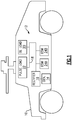
- FIG. 1 is a schematic view of an example vehicle 10 that includes an electrical power system 12.
- the electrical power system 12 includes a generator 14, rectifier 16, and DC bus 18.
- the generator 14 converts rotational movement (e.g., of a rotor of the vehicle 10) to electrical power.
- the rectifier 16 converts alternating current (AC) from the generator 14 to direct current (DC), and provides the DC to the DC bus 18.
- the rectifier 16 can be an active rectifier or a passive rectifier, for example.
- the generator 14 could be a permanent magnet machine or wound field synchronous generator, for example.
- a baseline load 20 and one or more pulse loads 22 are powered by the DC bus 18.
- the baseline load 20 could include vehicle controls, sensors, and/or other electrical devices of the vehicle 10, for example.
- the pulse load 22 could include one or more of a radar device and a directed energy weapon, for example.
- an infantry fighting vehicle 10 is depicted in Figure 1 , it is understood that the electrical power system 12 is not limited to ground vehicles, and could be used in other environments and vehicles, such as aircraft.
- the electrical power system 12 includes a plurality of energy storage modules (ESMs) 24A-B that are configured to charge from the DC bus 18 in a charging mode, and to act as supplemental power stages by providing supplemental power to the DC bus 18 in a discharging mode when the one or more pulse loads 22 are utilized.
- ESMs energy storage modules
- Each pulse load 22 needs a relatively large amount of power over a relatively short time duration, and the ESMs 24 are able to meet that power demand.
- FIG. 1 only two ESMs 24A-B are shown in Figure 1 , it is understood that additional ESMs 24 could be used if desired.
- like reference numerals designate like elements where appropriate and reference numerals with the addition of one-hundred or multiples thereof designate modified elements that are understood to incorporate the same features and benefits of the corresponding elements.
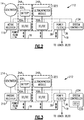
- FIG 2 is a schematic view of an example electrical power system 112 in which the rectifier 16 is an active rectifier 116.
- each ESM 24 includes a respective DC/DC converter 30 and at least one energy storage device 32.
- the energy storage devices 32 can include a variety of energy storage devices, such as batteries, fuel cells, and ultracapacitors, for example.
- Ultracapacitors are high-capacity capacitors that can typically store 10 - 100 times more energy per unit volume or mass than electrolytic capacitors.
- the energy storage device 32A of ESM 24A includes one or more batteries, and the energy storage device 32B of ESM 24B includes one or more ultracapacitors. In other examples, the energy storage devices 32A-B include the same type of energy storage device.
- Each ESM 24 includes a respective DC/DC converter 30 configured to control charging of its energy storage device 32 from the DC bus 18 and to control discharge of its energy storage device 32 onto the DC bus 18.
- the voltages of the energy storage devices 32 have a lower magnitude than that of the DC bus 18.
- the DC/DC converters 30 operate in a buck mode when charging the energy storage devices 32 and operate in a boost mode when discharging the energy storage devices 32.
- the DC/DC converters 30A-B convert the larger magnitude DC voltage from the DC bus 18 to a lower magnitude DC voltage for charging the energy storage devices 32. This is also known as "sinking" current from the DC bus 18.
- the DC/DC converters 30A-B convert the lower magnitude voltages of the energy storage devices 32 to the higher magnitude voltages of the DC bus 18 for discharging the energy storage devices 32 onto the DC bus. This is also known as "sourcing current" to the DC bus 18.
- a system controller 134 acts as a voltage regulator by controlling the active rectifier 116 to achieve desired DC voltage and DC current levels on the DC bus 18 based on measurements from a voltage sensor 36.
- the current demand on the DC bus 18 can change based on operation of the loads 20, 22, and the current output by the generator 14 can also change (e.g., based on an engine speed of the vehicle 10).
- the system controller 134 accommodates these operating conditions by adjusting the output of the active rectifier 116 to achieve a desired DC current and DC voltage on the DC bus 18 for powering the base line load 20.
- the system controller 134 also selectively discharging the ESMs 24 to power the one or more pulse loads 22.
- the generator 14 and ESM 24A-B function as current sources to support the voltage regulation provided by the system controller 134.
- the system controller 134 controls the DC/DC converters 30A-B to control charging and discharging of the ESMs 24.
- the system controller 134 is configured to maintain a desired "state of charge” (SoC) of the each energy storage devices 32.
- SoC refers to a charge level of the energy storage devices 32, and is akin to a fuel gauge for the energy storage devices 32.
- a SoC is generally measured as a percentage, where a SoC of 0 means that an energy storage device 32 has no charge and is "empty" and a SoC of 100 means that an energy storage device 32 is fully charged and is "full.”
- the system controller 134 seeks to maintain a threshold SoC level, such as 70%, in the energy storage devices 32.
- a “slew rate” refers to how fast a power source can respond to a load demand.
- a slew rate may be measured in kilowatts / millisecond, for example.
- the slew rate of the ESMs 24 is faster than the slew rate of the rectifier 116. This makes the ESMs 24 suitable for powering pulse loads 22 that need a relatively large amount of power over a relatively short time duration.
- the slew rate of the active rectifier 116 is on the order of 5 kw/ms and the slew rate of the ESMs is on the order of 300 kw/ms.
- Ultracapacitors typically have a higher slew rate than batteries.
- the system controller 134 is configured to control the active rectifier 116 and plurality of DC/DC converters 30 based on DC bus voltage measurements from the voltage sensor 36.
- the system controller 134 uses the voltage sensor 36 as part of a feedback loop so that the system controller 134 can monitor voltage levels on the DC bus and adjust the active rectifier 116 output accordingly.
- a pulse load 22 is activated, there is a spike in a power demand on the DC bus 18.
- the system controller 134 detects this spike, and in one example determines that the active rectifier will only be able to source a portion (e.g., 40%) of the demand. Based on the determination, the system controller 134 commands the DC/DC converter 30 of one or both of the ESMs 24 to discharge onto the DC bus to meet the remaining load demand of the pulse load 22.
- the system controller 134 also controls when the DC/DC converters 30 charge their respective energy storage devices 32 from the DC bus 18. In one example, the system controller 134 commands one or both of the DC/DC converters 30 to charge their respective energy storage devices 32 when an actual current on the DC bus 18 exceeds a target current level and/or when the SoC of the ESMs is below a threshold level. In one example, the system controller 134 includes a field-programmable gate array (FPGA), a microprocessor (e.g., a digital signal processor "DSP"), or a combination thereof.
- FPGA field-programmable gate array
- DSP digital signal processor
- the same system controller 134 is used to control the active rectifier 116 and the DC/DC converters 30A-B, and in this regard is a shared controller.
- separate controllers have been used for an active rectifier and ESM DC/DC converters, with each controller using its own control loop, and with the active rectifier being tuned to match the considerably slower response of a vehicle engine while an ESM serviced loads requiring a quicker response time (also known as "high bandwidth” loads).
- Such voltage trimming is not necessary with the shared system controller 134, because the system controller 134 is shared and can directly cause the DC/DC converters 30 to discharge without the need for voltage trimming.
- the improved coordination provided by the shared system controller 134 can also prevent other issues previously encountered due to use of separate controllers. For example, in the prior art, the controllers sometimes competed with each other such that the active rectifier controller would unnecessarily try to boost its output to meet a load demand on the DC bus that could have been met by an ESM. By using the shared system controller 134, such conflicts can be avoided.
- the shared system controller 134 also helps avoid potential instability issues. If separate controllers are used, and an erroneous sensor reading is received indicating a pulse load demand, an ESM could potentially discharge unnecessarily and cause a surge on the DC bus. Such an event is less likely when the shared system controller 134 is used.
- the voltage sensor 36 is part of a power filter 38 that provides for electromagnetic interference (EMI) filtering of the DC current on the DC bus 18.
- the power filter 38 is connected to the DC bus 18 at a location between that of the plurality of ESMs 24 and the loads 20, 22.
- the power filter 38 is also shared by the active rectifier 116 and ESMs 24. Unlike the prior art where separate power filters were used, the power filter 38 is shared, which removes the need for multiple power filters 38.
- FIG 3 is a schematic view of an example electrical power system 212 which uses a passive rectifier 216 instead of an active rectifier 116, and in which the generator 214 is a wound field synchronous generator.
- the passive rectifier 216 is not controlled by system controller 234.
- the system controller 234 includes a generator control unit (GCU) 239 that can adjust an output of the generator 14, and thereby control the output of the generator 14 that is provided to the passive rectifier 216.
- GCU generator control unit
- the system controller 234 can still influence the output of the passive rectifier 216 by controlling the GCU 239.
- the remaining components of the electrical power system 112 operate as described above in connection with Figure 2 .
- the generator 214 and ESM 24A-B function as current sources to support the voltage regulation provided by the system controller 234.
- the active rectifier 116 and GCU 239 operate as DC bus 18 current controllers because they can control a DC current that is provided on the DC bus 18.
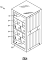
- FIG. 4 schematically illustrates an example mounting rack 50 for storing components of the electrical power system 112, 212.
- the mounting rack 50 defines a plurality of stacked receiving areas 52.
- one or more of the DC/DC converters 30, system controller 134/234, power filter 38, rectifier 116/216, and GCU 239 are provided on a plurality of circuit boards 54, each of which are mounted in the stacked receiving areas 52.
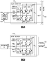
- FIG. 5 is a schematic view of an example implementation of the DC/DC converter 30, which utilizes a plurality of switching legs 62A-C.
- Each switching leg 62 connects to a respective line 68A-C.
- Each switching leg 62 includes a respective first switch 64 and a respective second switch 66.
- Each first switch 64 connects its line 68 to a positive rail 19A of the DC bus 18, and each second switch 66 connects its line 68 to a ground rail 19B of the DC bus 18.
- the lines 68 all connect to terminal 70A of the energy storage device 32.
- a gate drive 72 operates the switches 64, 66 to either charge the energy storage device 32 from the DC bus 18 (during which lines 68 act as inputs), or discharge the energy storage device 32 onto the DC bus 18 (during which lines 68 act as outputs).
- a capacitor C is connected in parallel to the switching legs 62A-C.
- the ground rail 19B may be a neutral rail that acts as a ground.
- the ground rail 19B could connect to a chassis of the vehicle 10 or a neutral terminal of the generator 14, for example
- Figure 6 is a schematic view of an example implementation of the active rectifier 116 which utilizes the same switching topology which includes the plurality of switching legs 62A-C, each including a respective pair of switches 64, 66.
- the inputs on lines 68A-C correspond to phases of current (shown as A, B, C) from the generator 14.
- a same circuit board 54 can be used for each of the DC/DC converter 30 and active rectifier 116 in the mounting rack 50 of Figure 4 .
- FIG. 7 is a schematic view of an example power control system 312 that utilizes a split DC bus 318 that includes a positive rail 319A that provides a positive voltage, a negative rail 319C that provides a negative voltage, and a ground rail 319B.
- ESMs 324A and 324C are connected in a "series stacked" configuration in which ESM 324A charges from and discharges onto the positive rail 319A, and ESM 324C charges from and discharges onto the negative rail 319C.
- ESMs 324B and 324D are also connected in a series stacked configuration in which ESM 324B charges from and discharges onto the positive rail 319A, and ESM 324D charges from and discharges onto the negative rail 319C.
- a same shared system controller 334 controls each of the DC/DC converters 330A-D of each of the ESMs 324A-D.
- Use of the split DC bus 318 is a technique to achieve a desired total bus voltage (e.g., 600 volts) by using smaller positive and negative rail voltages (e.g., +300 volts on positive rail 319A and -300 volts on negative rail 319C).
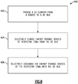
- FIG 8 is a flowchart 400 illustrative of an example method of controlling an electrical power system 12.
- DC current is provided from a source to a DC bus 18 (step 402).
- Step 402 could include using an active rectifier 116 and/or using a generator control unit 239 to control the DC current, for example.
- Energy storage devices 32A-B of respective ESMs 24 are selectively charged from the DC bus (step 404), and are selectively discharged onto the DC bus (step 406).
- Shared system controller 34 controls performance of steps 402-406.
Landscapes
- Engineering & Computer Science (AREA)
- Power Engineering (AREA)
- Transportation (AREA)
- Mechanical Engineering (AREA)
- Physics & Mathematics (AREA)
- Nonlinear Science (AREA)
- Life Sciences & Earth Sciences (AREA)
- Sustainable Development (AREA)
- Sustainable Energy (AREA)
- Dc-Dc Converters (AREA)
- Charge And Discharge Circuits For Batteries Or The Like (AREA)
Abstract
Description
- This application relates to electrical power systems, and more particularly, to an electrical power system that utilizes a shared system controller.
- Vehicles such as aircraft and infantry fighting vehicles (e.g., "HUMVEEs") often include electrical power systems with an on-board generator that provides electrical power. The generated electrical power is used to power on-board electrical components such as vehicle controls (e.g., ailerons and rudders in the case of an aircraft), sensors, and/or other on-board electrical devices. These items collectively act as a baseline electrical load that requires a baseline amount of electrical power.
- The vehicle may also include pulse loads that require supplemental power, causing a spike in the overall load of the electrical system. Some example pulse loads could include a radar or a directed energy weapon. On-board energy storage devices that charge from the generator can be used to provide supplemental power for pulse loads.
- An example electrical power system includes a bus current controller configured to adjust a direct current (DC) provided on a DC bus, and a plurality of energy storage modules (ESMs). Each ESM includes at least one energy storage device, and includes a DC/DC converter configured to control charging of the at least one energy storage device from the DC bus and discharging of the at least one energy storage device onto the DC bus. A shared system controller is configured to control the bus current controller and the plurality of DC/DC converters.
- An example method of controlling an electrical power system includes providing DC from a source to a DC bus, selectively charging energy storage devices of respective ESMs from the DC bus, and selectively discharging the energy storage devices of the respective ESMs onto the DC bus. Performance of said providing, selectively charging, and selectively discharging is controlled by a shared system controller.
- The embodiments, examples, and alternatives of the preceding paragraphs, the claims, or the following description and drawings, including any of their various aspects or respective individual features, may be taken independently or in any combination. Features described in connection with one embodiment are applicable to all embodiments, unless such features are incompatible.
-
-
Figure 1 is a schematic view of an example vehicle that includes an electrical power system. -
Figure 2 is a schematic view of an example of the electrical power system ofFigure 1 which uses an active rectifier. -
Figure 3 is a schematic view of an example of the electrical power system ofFigure 1 which uses a passive rectifier. -
Figure 4 schematically illustrates an example mounting rack for storing components of an electrical power system. -
Figure 5 is a schematic view of an example implementation of a DC/DC converter. -
Figure 6 is a schematic view of an example implementation of an active rectifier. -
Figure 7 is a schematic view of an example power control system that utilizes a split DC bus. -
Figure 8 is a flowchart illustrative of an example method of controlling an electrical power system. -
Figure 1 is a schematic view of anexample vehicle 10 that includes anelectrical power system 12. Theelectrical power system 12 includes agenerator 14,rectifier 16, andDC bus 18. Thegenerator 14 converts rotational movement (e.g., of a rotor of the vehicle 10) to electrical power. Therectifier 16 converts alternating current (AC) from thegenerator 14 to direct current (DC), and provides the DC to theDC bus 18. Therectifier 16 can be an active rectifier or a passive rectifier, for example. Thegenerator 14 could be a permanent magnet machine or wound field synchronous generator, for example. - A
baseline load 20 and one ormore pulse loads 22 are powered by theDC bus 18. Thebaseline load 20 could include vehicle controls, sensors, and/or other electrical devices of thevehicle 10, for example. Thepulse load 22 could include one or more of a radar device and a directed energy weapon, for example. Although aninfantry fighting vehicle 10 is depicted inFigure 1 , it is understood that theelectrical power system 12 is not limited to ground vehicles, and could be used in other environments and vehicles, such as aircraft. - The
electrical power system 12 includes a plurality of energy storage modules (ESMs) 24A-B that are configured to charge from theDC bus 18 in a charging mode, and to act as supplemental power stages by providing supplemental power to theDC bus 18 in a discharging mode when the one ormore pulse loads 22 are utilized. Eachpulse load 22 needs a relatively large amount of power over a relatively short time duration, and the ESMs 24 are able to meet that power demand. Although only twoESMs 24A-B are shown inFigure 1 , it is understood that additional ESMs 24 could be used if desired. - In this disclosure, like reference numerals designate like elements where appropriate and reference numerals with the addition of one-hundred or multiples thereof designate modified elements that are understood to incorporate the same features and benefits of the corresponding elements.
-
Figure 2 is a schematic view of an exampleelectrical power system 112 in which therectifier 16 is anactive rectifier 116. As shown inFigure 2 , each ESM 24 includes a respective DC/DC converter 30 and at least oneenergy storage device 32. Theenergy storage devices 32 can include a variety of energy storage devices, such as batteries, fuel cells, and ultracapacitors, for example. Ultracapacitors are high-capacity capacitors that can typically store 10 - 100 times more energy per unit volume or mass than electrolytic capacitors. - In the example of
Figure 2 , theenergy storage device 32A of ESM 24A includes one or more batteries, and theenergy storage device 32B of ESM 24B includes one or more ultracapacitors. In other examples, theenergy storage devices 32A-B include the same type of energy storage device. - Each ESM 24 includes a respective DC/DC converter 30 configured to control charging of its
energy storage device 32 from theDC bus 18 and to control discharge of itsenergy storage device 32 onto theDC bus 18. - In one example, the voltages of the
energy storage devices 32 have a lower magnitude than that of theDC bus 18. In such an example, the DC/DC converters 30 operate in a buck mode when charging theenergy storage devices 32 and operate in a boost mode when discharging theenergy storage devices 32. In the buck mode, the DC/DC converters 30A-B convert the larger magnitude DC voltage from theDC bus 18 to a lower magnitude DC voltage for charging theenergy storage devices 32. This is also known as "sinking" current from theDC bus 18. - In the boost mode, the DC/
DC converters 30A-B convert the lower magnitude voltages of theenergy storage devices 32 to the higher magnitude voltages of theDC bus 18 for discharging theenergy storage devices 32 onto the DC bus. This is also known as "sourcing current" to theDC bus 18. - A
system controller 134 acts as a voltage regulator by controlling theactive rectifier 116 to achieve desired DC voltage and DC current levels on theDC bus 18 based on measurements from avoltage sensor 36. The current demand on theDC bus 18 can change based on operation of theloads generator 14 can also change (e.g., based on an engine speed of the vehicle 10). Thesystem controller 134 accommodates these operating conditions by adjusting the output of theactive rectifier 116 to achieve a desired DC current and DC voltage on theDC bus 18 for powering thebase line load 20. Thesystem controller 134 also selectively discharging the ESMs 24 to power the one ormore pulse loads 22. In this regard, thegenerator 14 andESM 24A-B function as current sources to support the voltage regulation provided by thesystem controller 134. - The
system controller 134 controls the DC/DC converters 30A-B to control charging and discharging of the ESMs 24. Thesystem controller 134 is configured to maintain a desired "state of charge" (SoC) of the eachenergy storage devices 32. SoC refers to a charge level of theenergy storage devices 32, and is akin to a fuel gauge for theenergy storage devices 32. A SoC is generally measured as a percentage, where a SoC of 0 means that anenergy storage device 32 has no charge and is "empty" and a SoC of 100 means that anenergy storage device 32 is fully charged and is "full." In one example, thesystem controller 134 seeks to maintain a threshold SoC level, such as 70%, in theenergy storage devices 32. - A "slew rate" refers to how fast a power source can respond to a load demand. A slew rate may be measured in kilowatts / millisecond, for example. The slew rate of the ESMs 24 is faster than the slew rate of the
rectifier 116. This makes the ESMs 24 suitable for powering pulse loads 22 that need a relatively large amount of power over a relatively short time duration. In one example, the slew rate of theactive rectifier 116 is on the order of 5 kw/ms and the slew rate of the ESMs is on the order of 300 kw/ms. Ultracapacitors typically have a higher slew rate than batteries. - The
system controller 134 is configured to control theactive rectifier 116 and plurality of DC/DC converters 30 based on DC bus voltage measurements from thevoltage sensor 36. Thesystem controller 134 uses thevoltage sensor 36 as part of a feedback loop so that thesystem controller 134 can monitor voltage levels on the DC bus and adjust theactive rectifier 116 output accordingly. When apulse load 22 is activated, there is a spike in a power demand on theDC bus 18. Thesystem controller 134 detects this spike, and in one example determines that the active rectifier will only be able to source a portion (e.g., 40%) of the demand. Based on the determination, thesystem controller 134 commands the DC/DC converter 30 of one or both of the ESMs 24 to discharge onto the DC bus to meet the remaining load demand of thepulse load 22. - The
system controller 134 also controls when the DC/DC converters 30 charge their respectiveenergy storage devices 32 from theDC bus 18. In one example, thesystem controller 134 commands one or both of the DC/DC converters 30 to charge their respectiveenergy storage devices 32 when an actual current on theDC bus 18 exceeds a target current level and/or when the SoC of the ESMs is below a threshold level. In one example, thesystem controller 134 includes a field-programmable gate array (FPGA), a microprocessor (e.g., a digital signal processor "DSP"), or a combination thereof. - The
same system controller 134 is used to control theactive rectifier 116 and the DC/DC converters 30A-B, and in this regard is a shared controller. In the prior art, separate controllers have been used for an active rectifier and ESM DC/DC converters, with each controller using its own control loop, and with the active rectifier being tuned to match the considerably slower response of a vehicle engine while an ESM serviced loads requiring a quicker response time (also known as "high bandwidth" loads). This led to redundancies, complex control algorithms, and use of a feature called "voltage trimming" whereby if the active rectifier controller wanted the ESMs 24 to discharge, it would intentionally "trim" the voltage on the DC bus to a lower value to cause the ESMs 24 to discharge. Such voltage trimming is not necessary with the sharedsystem controller 134, because thesystem controller 134 is shared and can directly cause the DC/DC converters 30 to discharge without the need for voltage trimming. - The improved coordination provided by the shared
system controller 134 can also prevent other issues previously encountered due to use of separate controllers. For example, in the prior art, the controllers sometimes competed with each other such that the active rectifier controller would unnecessarily try to boost its output to meet a load demand on the DC bus that could have been met by an ESM. By using the sharedsystem controller 134, such conflicts can be avoided. - The shared
system controller 134 also helps avoid potential instability issues. If separate controllers are used, and an erroneous sensor reading is received indicating a pulse load demand, an ESM could potentially discharge unnecessarily and cause a surge on the DC bus. Such an event is less likely when the sharedsystem controller 134 is used. - The
voltage sensor 36 is part of apower filter 38 that provides for electromagnetic interference (EMI) filtering of the DC current on theDC bus 18. In the example ofFigure 2 , thepower filter 38 is connected to theDC bus 18 at a location between that of the plurality of ESMs 24 and theloads power filter 38 is also shared by theactive rectifier 116 and ESMs 24. Unlike the prior art where separate power filters were used, thepower filter 38 is shared, which removes the need for multiple power filters 38. -
Figure 3 is a schematic view of an exampleelectrical power system 212 which uses apassive rectifier 216 instead of anactive rectifier 116, and in which thegenerator 214 is a wound field synchronous generator. Thepassive rectifier 216 is not controlled bysystem controller 234. However, thesystem controller 234 includes a generator control unit (GCU) 239 that can adjust an output of thegenerator 14, and thereby control the output of thegenerator 14 that is provided to thepassive rectifier 216. Thus, even though operation of thepassive rectifier 216 itself is not controlled, thesystem controller 234 can still influence the output of thepassive rectifier 216 by controlling theGCU 239. The remaining components of theelectrical power system 112 operate as described above in connection withFigure 2 . Here too, thegenerator 214 andESM 24A-B function as current sources to support the voltage regulation provided by thesystem controller 234. - In the embodiments of
Figures 2-3 , theactive rectifier 116 andGCU 239 operate asDC bus 18 current controllers because they can control a DC current that is provided on theDC bus 18. -
Figure 4 schematically illustrates anexample mounting rack 50 for storing components of theelectrical power system rack 50 defines a plurality of stacked receivingareas 52. In one example, one or more of the DC/DC converters 30,system controller 134/234,power filter 38,rectifier 116/216, andGCU 239 are provided on a plurality ofcircuit boards 54, each of which are mounted in the stacked receivingareas 52. - Although six slots are shown in
Figure 4 , with four of those slots includingcircuit boards 54, it is understood that this is a non-limiting example and that other quantities of slots and boards could be used. -
Figure 5 is a schematic view of an example implementation of the DC/DC converter 30, which utilizes a plurality of switching legs 62A-C. Each switching leg 62 connects to arespective line 68A-C. Each switching leg 62 includes a respective first switch 64 and a respective second switch 66. Each first switch 64 connects its line 68 to apositive rail 19A of theDC bus 18, and each second switch 66 connects its line 68 to aground rail 19B of theDC bus 18. The lines 68 all connect to terminal 70A of theenergy storage device 32. Agate drive 72 operates the switches 64, 66 to either charge theenergy storage device 32 from the DC bus 18 (during which lines 68 act as inputs), or discharge theenergy storage device 32 onto the DC bus 18 (during which lines 68 act as outputs). A capacitor C is connected in parallel to the switching legs 62A-C. - In the case of a vehicle such as an aircraft, the
ground rail 19B may be a neutral rail that acts as a ground. In such an example, theground rail 19B could connect to a chassis of thevehicle 10 or a neutral terminal of thegenerator 14, for example -
Figure 6 is a schematic view of an example implementation of theactive rectifier 116 which utilizes the same switching topology which includes the plurality of switching legs 62A-C, each including a respective pair of switches 64, 66. In the example ofFigure 6 , the inputs onlines 68A-C correspond to phases of current (shown as A, B, C) from thegenerator 14. In one example, because the DC/DC converter 30 andactive rectifier 116 use the same circuit topology, asame circuit board 54 can be used for each of the DC/DC converter 30 andactive rectifier 116 in the mountingrack 50 ofFigure 4 . -
Figure 7 is a schematic view of an examplepower control system 312 that utilizes asplit DC bus 318 that includes apositive rail 319A that provides a positive voltage, anegative rail 319C that provides a negative voltage, and aground rail 319B.ESMs ESM 324A charges from and discharges onto thepositive rail 319A, andESM 324C charges from and discharges onto thenegative rail 319C. Similarly,ESMs ESM 324B charges from and discharges onto thepositive rail 319A, andESM 324D charges from and discharges onto thenegative rail 319C. A same sharedsystem controller 334 controls each of the DC/DC converters 330A-D of each of theESMs 324A-D. Use of thesplit DC bus 318 is a technique to achieve a desired total bus voltage (e.g., 600 volts) by using smaller positive and negative rail voltages (e.g., +300 volts onpositive rail 319A and -300 volts onnegative rail 319C). -
Figure 8 is aflowchart 400 illustrative of an example method of controlling anelectrical power system 12. DC current is provided from a source to a DC bus 18 (step 402). Step 402 could include using anactive rectifier 116 and/or using agenerator control unit 239 to control the DC current, for example.Energy storage devices 32A-B of respective ESMs 24 are selectively charged from the DC bus (step 404), and are selectively discharged onto the DC bus (step 406). Shared system controller 34 controls performance of steps 402-406. - Although example embodiments have been disclosed, a worker of ordinary skill in this art would recognize that certain modifications would come within the scope of the invention as defined by the claims. For that reason, the following claims should be studied to determine the scope of the invention.
Claims (15)
- An electrical power system, comprising:a bus current controller configured to adjust a direct current, DC provided on a DC bus (18);a plurality of energy storage modules, ESMs (24), each comprising at least one energy storage device (32), and a DC/DC converter configured to control charging of the at least one energy storage device (32) from the DC bus and discharging of the at least one energy storage device onto the DC bus; anda shared system controller (134) configured to control the bus current controller and the plurality of DC/DC converters.
- The electrical power system of claim 1, wherein the at least one energy storage device of a first of the ESMs comprises a first type of energy storage device, and the at least one energy storage device of second of the ESMs comprises a second type of energy storage device that is different from the first type of energy storage device.
- The electrical power system of claim 1 or 2, wherein the at least one energy storage device of one of the ESMs comprises one or more batteries, or wherein the at least one energy storage device of one of the ESMs comprises one or more ultracapacitors.
- The electrical power system of any preceding claim, comprising:a voltage sensor (36) configured to measure a voltage on the DC bus;wherein the shared system controller is configured to control the bus current controller and the plurality of DC/DC converters (30) based on DC bus voltage measurements from the voltage sensor.
- The electrical power system of any preceding claim, wherein the bus current controller comprises an active rectifier (16) configured to rectify alternating current, AC, from a generator to DC on the DC bus, and preferably wherein the active rectifier and DC/DC converters each utilize a same switching topology.
- The electrical power system of claim 5, wherein:the active rectifier and DC/DC converters each comprise a plurality of switching legs (62), each switching leg comprising a pair of switches (64,66) and controlling connection of a respective input to the DC bus;wherein the respective inputs of the DC/DC converters each connect to the DC bus; andwherein the respective inputs of the active rectifier comprise respective phases of current from the generator.
- The electrical power system of claim 6, comprising:a mounting rack (50) defining a plurality of stacked receiving areas;wherein the DC/DC converters, shared system controller, and bus current controller are provided on a plurality of circuit boards, each circuit board mounted in one of the stacked receiving areas.
- The electrical power system of any preceding claim, comprising:a passive rectifier configured to rectify alternating current, AC, from a generator to DC on the DC bus;wherein the bus current controller comprises a generator control unit configured to control an output of the generator that is provided to the passive rectifier.
- The electrical power system of any preceding claim, comprising:
a power filter (38) connected to the DC bus between the plurality of ESMs and a plurality of loads, the power filter configured to provide electromagnetic interference (EMI) filtering for the DC current on the DC bus. - The electrical power system of claim 1, wherein the shared system controller is configured to discharge at least one of the ESMs onto the DC bus based on activation of a pulse load connected to the DC bus, or wherein the shared system controller is configured to charge at least one of the ESMs from the DC bus based on a current on the DC bus exceeding a target current level determined by the shared system controller.
- The electrical power system of any preceding claim, wherein:the DC bus comprises a positive rail (319A) configured to provide a positive DC voltage, a negative rail (319C) configured to provide a negative DC voltage, and a ground rail (319B);one of the ESMs that includes an energy storage device of a first type is connected to the positive rail and ground rail, but not the negative rail; andanother of the ESMs that includes an energy storage device of the first type is connected to the negative rail and the ground rail, but not the positive rail.
- A method of controlling an electrical power system, comprising:providing direct current, DC, from a source to a DC bus;selectively charging energy storage devices of respective energy storage modules, ESMs, from the DC bus;selectively discharging the energy storage devices of the respective ESMs onto the DC bus; andcontrolling performance of said providing, selectively charging, and selectively discharging by a shared system controller.
- The method of claim 12, wherein:said providing DC from the source to the DC bus comprises rectifying alternating current, AC, from a generator to DC using an active rectifier; andsaid controlling performance of said providing comprises the shared system controller controlling the active rectifier.
- The method of claim 12, wherein said selectively discharging comprises:detecting activation of a pulse load connected to the DC bus; and discharging at least one of the ESMs onto the DC bus based on the detected activation; or wherein:said selectively charging energy storage devices of respective ESMs from the DC bus comprises operating respective DC/DC converters of the ESMs in a buck mode;said selectively discharging the energy storage devices of the respective ESMs onto the DC bus comprises operating respective DC/DC converters of the ESMs in a boost mode.
- The method of claim 12, comprising:determining that a current on the DC bus exceeds a target current level;wherein said selectively charging energy storage devices of respective ESMs from the DC bus is performed based on the determining.
Applications Claiming Priority (1)
| Application Number | Priority Date | Filing Date | Title |
|---|---|---|---|
| US15/988,238 US11870249B2 (en) | 2018-05-24 | 2018-05-24 | Electrical power system including energy storage modules and shared system controller |
Publications (1)
| Publication Number | Publication Date |
|---|---|
| EP3573207A1 true EP3573207A1 (en) | 2019-11-27 |
Family
ID=66647177
Family Applications (1)
| Application Number | Title | Priority Date | Filing Date |
|---|---|---|---|
| EP19176303.6A Pending EP3573207A1 (en) | 2018-05-24 | 2019-05-23 | Electrical power system including energy storage modules and shared system controller |
Country Status (2)
| Country | Link |
|---|---|
| US (2) | US11870249B2 (en) |
| EP (1) | EP3573207A1 (en) |
Cited By (1)
| Publication number | Priority date | Publication date | Assignee | Title |
|---|---|---|---|---|
| US20260012018A1 (en) * | 2022-12-08 | 2026-01-08 | Hitachi Energy Ltd | An energy storage system for a direct current transmission system and a method for exchanging energy with a direct current transmission system |
Families Citing this family (6)
| Publication number | Priority date | Publication date | Assignee | Title |
|---|---|---|---|---|
| US10869394B1 (en) * | 2019-12-02 | 2020-12-15 | Management Services Group, Inc. | Apparatus and methods for reducing unintended transport of data from power distribution systems using layered power filters |
| EP3893359A1 (en) | 2020-04-08 | 2021-10-13 | Hamilton Sundstrand Corporation | Drive system |
| EP4148934A3 (en) * | 2021-09-14 | 2023-03-29 | General Electric Company | Loading sharing across multiple power supplies |
| US11901758B2 (en) | 2021-09-14 | 2024-02-13 | General Electric Company | Loading sharing across multiple power supplies |
| US12506343B2 (en) * | 2022-05-23 | 2025-12-23 | The Board Of Trustees Of The University Of Illinois | Generator-rectifier system and grid interface |
| JP7748918B2 (en) * | 2022-06-17 | 2025-10-03 | 本田技研工業株式会社 | power supply |
Citations (4)
| Publication number | Priority date | Publication date | Assignee | Title |
|---|---|---|---|---|
| US20110140649A1 (en) * | 2009-12-15 | 2011-06-16 | Looney Choi | Energy storage system |
| US20120013182A1 (en) * | 2009-04-23 | 2012-01-19 | Toyota Jidosha Kabushiki Kaisha | Power source system for electric powered vehicle and control method therefor |
| US20170063124A1 (en) * | 2015-08-31 | 2017-03-02 | Caterpillar Inc. | Control of Hybrid Energy Storage System for High Pulse Load |
| US20180041028A1 (en) * | 2016-08-05 | 2018-02-08 | Hamilton Sundstrand Corporation | Hybrid energy storage module arrangements |
Family Cites Families (30)
| Publication number | Priority date | Publication date | Assignee | Title |
|---|---|---|---|---|
| US7100717B2 (en) | 2002-10-31 | 2006-09-05 | General Motors Corporation | Integrated electric power take-off system |
| EP1639684A2 (en) * | 2003-06-27 | 2006-03-29 | Maxwell Technologies, Inc. | Energy storage system |
| JP4780402B2 (en) * | 2006-06-27 | 2011-09-28 | 株式会社デンソー | Vehicle power supply |
| EP2143124A4 (en) * | 2007-04-04 | 2017-06-28 | Cooper Technologies Company | System and method for boosting battery output |
| JP2012034554A (en) * | 2009-08-21 | 2012-02-16 | Jfe Engineering Corp | Fast charger |
| US8245801B2 (en) * | 2009-11-05 | 2012-08-21 | Bluways Usa, Inc. | Expandable energy storage control system architecture |
| US20110114625A1 (en) * | 2009-11-16 | 2011-05-19 | Prince Castle, Inc | Food holding cabinet with self-aligning and addressable power supplies |
| US8427108B2 (en) * | 2010-08-19 | 2013-04-23 | Hamilton Sundstrand Corporation | Method for controlling an electric accumulator unit |
| US8606444B2 (en) * | 2010-12-29 | 2013-12-10 | Caterpillar Inc. | Machine and power system with electrical energy storage device |
| US20140009117A1 (en) * | 2011-03-30 | 2014-01-09 | Sanyo Electric Co., Ltd. | Electrical storage system and mobile body |
| US9698598B2 (en) * | 2011-06-27 | 2017-07-04 | Bloom Energy Corporation | Electrical vehicle charging using fuel cell system |
| US9496748B2 (en) * | 2011-10-25 | 2016-11-15 | General Electric Company | Integrated power system control method and related apparatus with energy storage element |
| US20140156099A1 (en) * | 2012-12-05 | 2014-06-05 | Cummins Power Generation, Inc. | Generator power systems with active and passive rectifiers |
| US20160001662A1 (en) * | 2013-02-25 | 2016-01-07 | Ut-Battelle, Llc | Buffering energy storage systems for reduced grid and vehicle battery stress for in-motion wireless power transfer systems |
| US10122180B2 (en) * | 2014-10-08 | 2018-11-06 | Parker-Hannifin Corporation | Bus conditioner for an aircraft power system |
| US9837996B2 (en) | 2015-01-07 | 2017-12-05 | Raytheon Company | Method and apparatus for control of pulsed power in hybrid energy storage module |
| US10447045B2 (en) * | 2015-01-30 | 2019-10-15 | Sony Corporation | Power control device, power control method, and power control system |
| US10044190B2 (en) * | 2015-04-30 | 2018-08-07 | Zyntony, Inc. | Distributed energy system with four conductor bipolar DC bus |
| JP6502758B2 (en) * | 2015-06-15 | 2019-04-17 | 川崎重工業株式会社 | DC stabilized power supply system |
| US10283966B2 (en) * | 2015-07-31 | 2019-05-07 | Bluvert Technologies Ltd. | System and methods for power generation |
| US20170214251A1 (en) * | 2016-01-21 | 2017-07-27 | General Electric Company | Energy Storage Systems With Enhanced Storage and Discharge Response Allocation |
| US10876510B2 (en) * | 2016-03-02 | 2020-12-29 | Gentherm Incorporated | Systems and methods for supplying power in a hybrid vehicle using capacitors, a battery and one or more DC/DC converters |
| US20170256957A1 (en) | 2016-03-04 | 2017-09-07 | G4 Synergetics, Inc. | Hybrid power delivery with improved power control |
| US9969273B2 (en) * | 2016-07-12 | 2018-05-15 | Hamilton Sundstrand Corporation | Integrated modular electric power system for a vehicle |
| US9774263B1 (en) * | 2016-08-05 | 2017-09-26 | Schneider Electric It Corporation | Power converter with extended hold-up time |
| US10486537B2 (en) * | 2016-08-29 | 2019-11-26 | Hamilton Sundstrand Corporation | Power generating systems having synchronous generator multiplex windings and multilevel inverters |
| US20190031125A1 (en) * | 2017-07-25 | 2019-01-31 | Hamilton Sundstrand Corporation | Electric system architecture for range extended electric vehicles |
| WO2019036552A1 (en) * | 2017-08-16 | 2019-02-21 | Claudio Filippone | Locomotive waste heat recovery system and related methods |
| KR102444737B1 (en) * | 2017-11-21 | 2022-09-19 | 고쿠리쓰 겐큐 가이하쓰 호징 리가가쿠 겐큐소 | DC bus control system |
| PL3572269T3 (en) * | 2018-05-23 | 2022-02-07 | Sandvik Mining And Construction Oy | System and method for supplying electric energy to a mining vehicle and a mining vehicle |
-
2018
- 2018-05-24 US US15/988,238 patent/US11870249B2/en active Active
-
2019
- 2019-05-23 EP EP19176303.6A patent/EP3573207A1/en active Pending
-
2023
- 2023-11-02 US US18/500,373 patent/US12184063B2/en active Active
Patent Citations (4)
| Publication number | Priority date | Publication date | Assignee | Title |
|---|---|---|---|---|
| US20120013182A1 (en) * | 2009-04-23 | 2012-01-19 | Toyota Jidosha Kabushiki Kaisha | Power source system for electric powered vehicle and control method therefor |
| US20110140649A1 (en) * | 2009-12-15 | 2011-06-16 | Looney Choi | Energy storage system |
| US20170063124A1 (en) * | 2015-08-31 | 2017-03-02 | Caterpillar Inc. | Control of Hybrid Energy Storage System for High Pulse Load |
| US20180041028A1 (en) * | 2016-08-05 | 2018-02-08 | Hamilton Sundstrand Corporation | Hybrid energy storage module arrangements |
Non-Patent Citations (1)
| Title |
|---|
| ELSIED M ET AL: "Real-time implementation of four-phase interleaved DC-DC boost converter for electric vehicle power system", ELECTRIC POWER SYSTEMS RESEARCH, ELSEVIER, AMSTERDAM, NL, vol. 141, 17 August 2016 (2016-08-17), pages 210 - 220, XP029755527, ISSN: 0378-7796, DOI: 10.1016/J.EPSR.2016.07.028 * |
Cited By (2)
| Publication number | Priority date | Publication date | Assignee | Title |
|---|---|---|---|---|
| US20260012018A1 (en) * | 2022-12-08 | 2026-01-08 | Hitachi Energy Ltd | An energy storage system for a direct current transmission system and a method for exchanging energy with a direct current transmission system |
| US12573847B2 (en) * | 2022-12-08 | 2026-03-10 | Hitachi Energy Ltd | Energy storage system for a direct current transmission system and a method for exchanging energy with a direct current transmission system |
Also Published As
| Publication number | Publication date |
|---|---|
| US20240063635A1 (en) | 2024-02-22 |
| US20190359064A1 (en) | 2019-11-28 |
| US12184063B2 (en) | 2024-12-31 |
| US11870249B2 (en) | 2024-01-09 |
Similar Documents
| Publication | Publication Date | Title |
|---|---|---|
| US12184063B2 (en) | Electrical power system including energy storage modules and shared system controller | |
| US8884561B2 (en) | AC motor driving apparatus | |
| CA2950151C (en) | Engine start and battery support module | |
| US7554214B2 (en) | Large transient detection for electric power generation | |
| JP6731607B2 (en) | Power conversion system | |
| US10951126B2 (en) | System and method for operating a system | |
| US10322687B2 (en) | Stabilization circuit for a vehicle electrical system | |
| WO2015200437A1 (en) | Battery backup units and systems including bypassing circuitry for regulating outputs | |
| EP3255755B1 (en) | High voltage power generating system | |
| EP3703239A1 (en) | Electrical power system for pulsed loads including an active rectifier | |
| EP2371056A1 (en) | Electric energy storage integrated within or proximate to electrically driven flight control actuators | |
| EP4376244A2 (en) | Ultracapacitor module | |
| EP3255762B1 (en) | Switched reluctance generator based automotive power generating system | |
| US20180212457A1 (en) | Method and device for operating an electrical system, and electrical system | |
| EP4376256A1 (en) | Ultracapacitor module with adaptive bus voltage control system | |
| US8427108B2 (en) | Method for controlling an electric accumulator unit | |
| JP4054776B2 (en) | Hybrid system | |
| JP4896044B2 (en) | Power converter | |
| EP2492132B1 (en) | Drive device for railway vehicle | |
| Khadse et al. | Design of battery storage system for Microgrid | |
| EP3550690B1 (en) | Electrical power system with multiple energy storage modules | |
| Joshi et al. | Average current mode control of battery/ultracapacitor hybrid energy system & its microcontroller based implementation | |
| WO2016004327A1 (en) | Systems and methods for matching end of life for multiple batteries and/or battery backup units | |
| WO2019081814A1 (en) | Dc to dc converter module and method of control for the same | |
| KR101811149B1 (en) | Power Conditioning System for Controlling Reactive Power and Energy Storage System Including The Same |
Legal Events
| Date | Code | Title | Description |
|---|---|---|---|
| PUAI | Public reference made under article 153(3) epc to a published international application that has entered the european phase |
Free format text: ORIGINAL CODE: 0009012 |
|
| STAA | Information on the status of an ep patent application or granted ep patent |
Free format text: STATUS: THE APPLICATION HAS BEEN PUBLISHED |
|
| AK | Designated contracting states |
Kind code of ref document: A1 Designated state(s): AL AT BE BG CH CY CZ DE DK EE ES FI FR GB GR HR HU IE IS IT LI LT LU LV MC MK MT NL NO PL PT RO RS SE SI SK SM TR |
|
| AX | Request for extension of the european patent |
Extension state: BA ME |
|
| STAA | Information on the status of an ep patent application or granted ep patent |
Free format text: STATUS: REQUEST FOR EXAMINATION WAS MADE |
|
| 17P | Request for examination filed |
Effective date: 20191202 |
|
| RBV | Designated contracting states (corrected) |
Designated state(s): AL AT BE BG CH CY CZ DE DK EE ES FI FR GB GR HR HU IE IS IT LI LT LU LV MC MK MT NL NO PL PT RO RS SE SI SK SM TR |
|
| STAA | Information on the status of an ep patent application or granted ep patent |
Free format text: STATUS: EXAMINATION IS IN PROGRESS |
|
| 17Q | First examination report despatched |
Effective date: 20211028 |