EP3573172A1 - Heating control method and heating control device - Google Patents
Heating control method and heating control device Download PDFInfo
- Publication number
- EP3573172A1 EP3573172A1 EP19150225.1A EP19150225A EP3573172A1 EP 3573172 A1 EP3573172 A1 EP 3573172A1 EP 19150225 A EP19150225 A EP 19150225A EP 3573172 A1 EP3573172 A1 EP 3573172A1
- Authority
- EP
- European Patent Office
- Prior art keywords
- current value
- cycle
- value
- battery pack
- average current
- Prior art date
- Legal status (The legal status is an assumption and is not a legal conclusion. Google has not performed a legal analysis and makes no representation as to the accuracy of the status listed.)
- Granted
Links
Images


Classifications
-
- H—ELECTRICITY
- H05—ELECTRIC TECHNIQUES NOT OTHERWISE PROVIDED FOR
- H05B—ELECTRIC HEATING; ELECTRIC LIGHT SOURCES NOT OTHERWISE PROVIDED FOR; CIRCUIT ARRANGEMENTS FOR ELECTRIC LIGHT SOURCES, IN GENERAL
- H05B1/00—Details of electric heating devices
- H05B1/02—Automatic switching arrangements specially adapted to apparatus ; Control of heating devices
- H05B1/0227—Applications
- H05B1/023—Industrial applications
-
- H—ELECTRICITY
- H01—ELECTRIC ELEMENTS
- H01M—PROCESSES OR MEANS, e.g. BATTERIES, FOR THE DIRECT CONVERSION OF CHEMICAL ENERGY INTO ELECTRICAL ENERGY
- H01M10/00—Secondary cells; Manufacture thereof
- H01M10/60—Heating or cooling; Temperature control
- H01M10/61—Types of temperature control
- H01M10/615—Heating or keeping warm
-
- H—ELECTRICITY
- H01—ELECTRIC ELEMENTS
- H01M—PROCESSES OR MEANS, e.g. BATTERIES, FOR THE DIRECT CONVERSION OF CHEMICAL ENERGY INTO ELECTRICAL ENERGY
- H01M10/00—Secondary cells; Manufacture thereof
- H01M10/42—Methods or arrangements for servicing or maintenance of secondary cells or secondary half-cells
- H01M10/425—Structural combination with electronic components, e.g. electronic circuits integrated to the outside of the casing
-
- H—ELECTRICITY
- H01—ELECTRIC ELEMENTS
- H01M—PROCESSES OR MEANS, e.g. BATTERIES, FOR THE DIRECT CONVERSION OF CHEMICAL ENERGY INTO ELECTRICAL ENERGY
- H01M10/00—Secondary cells; Manufacture thereof
- H01M10/60—Heating or cooling; Temperature control
- H01M10/63—Control systems
- H01M10/633—Control systems characterised by algorithms, flow charts, software details or the like
-
- H—ELECTRICITY
- H01—ELECTRIC ELEMENTS
- H01M—PROCESSES OR MEANS, e.g. BATTERIES, FOR THE DIRECT CONVERSION OF CHEMICAL ENERGY INTO ELECTRICAL ENERGY
- H01M10/00—Secondary cells; Manufacture thereof
- H01M10/60—Heating or cooling; Temperature control
- H01M10/65—Means for temperature control structurally associated with the cells
- H01M10/651—Means for temperature control structurally associated with the cells characterised by parameters specified by a numeric value or mathematical formula, e.g. ratios, sizes or concentrations
-
- H—ELECTRICITY
- H01—ELECTRIC ELEMENTS
- H01M—PROCESSES OR MEANS, e.g. BATTERIES, FOR THE DIRECT CONVERSION OF CHEMICAL ENERGY INTO ELECTRICAL ENERGY
- H01M10/00—Secondary cells; Manufacture thereof
- H01M10/60—Heating or cooling; Temperature control
- H01M10/65—Means for temperature control structurally associated with the cells
- H01M10/657—Means for temperature control structurally associated with the cells by electric or electromagnetic means
- H01M10/6571—Resistive heaters
-
- G—PHYSICS
- G01—MEASURING; TESTING
- G01R—MEASURING ELECTRIC VARIABLES; MEASURING MAGNETIC VARIABLES
- G01R19/00—Arrangements for measuring currents or voltages or for indicating presence or sign thereof
- G01R19/165—Indicating that current or voltage is either above or below a predetermined value or within or outside a predetermined range of values
- G01R19/16528—Indicating that current or voltage is either above or below a predetermined value or within or outside a predetermined range of values using digital techniques or performing arithmetic operations
-
- G—PHYSICS
- G01—MEASURING; TESTING
- G01R—MEASURING ELECTRIC VARIABLES; MEASURING MAGNETIC VARIABLES
- G01R31/00—Arrangements for testing electric properties; Arrangements for locating electric faults; Arrangements for electrical testing characterised by what is being tested not provided for elsewhere
- G01R31/36—Arrangements for testing, measuring or monitoring the electrical condition of accumulators or electric batteries, e.g. capacity or state of charge [SoC]
- G01R31/382—Arrangements for monitoring battery or accumulator variables, e.g. SoC
-
- H—ELECTRICITY
- H01—ELECTRIC ELEMENTS
- H01M—PROCESSES OR MEANS, e.g. BATTERIES, FOR THE DIRECT CONVERSION OF CHEMICAL ENERGY INTO ELECTRICAL ENERGY
- H01M10/00—Secondary cells; Manufacture thereof
- H01M10/42—Methods or arrangements for servicing or maintenance of secondary cells or secondary half-cells
- H01M10/425—Structural combination with electronic components, e.g. electronic circuits integrated to the outside of the casing
- H01M2010/4271—Battery management systems including electronic circuits, e.g. control of current or voltage to keep battery in healthy state, cell balancing
-
- Y—GENERAL TAGGING OF NEW TECHNOLOGICAL DEVELOPMENTS; GENERAL TAGGING OF CROSS-SECTIONAL TECHNOLOGIES SPANNING OVER SEVERAL SECTIONS OF THE IPC; TECHNICAL SUBJECTS COVERED BY FORMER USPC CROSS-REFERENCE ART COLLECTIONS [XRACs] AND DIGESTS
- Y02—TECHNOLOGIES OR APPLICATIONS FOR MITIGATION OR ADAPTATION AGAINST CLIMATE CHANGE
- Y02E—REDUCTION OF GREENHOUSE GAS [GHG] EMISSIONS, RELATED TO ENERGY GENERATION, TRANSMISSION OR DISTRIBUTION
- Y02E60/00—Enabling technologies; Technologies with a potential or indirect contribution to GHG emissions mitigation
- Y02E60/10—Energy storage using batteries
Definitions
- the invention relates to the technical field of battery, and in particular, to a heating control method and a heating control device
- a power battery pack When a power battery pack has a temperature lower than a lower limit of an allowable operating temperature range, the power battery pack cannot work and needs to be heated to a temperature within the allowable operating temperature range before it resumes its operations.
- a method for heating a power battery pack includes: controlling a switch device to instantaneously short a power battery to form a heating circuit, such that an internal resistance of the power battery generates heat when a large current generated by instantaneous shorting flows through the internal resistance, thereby heating the power battery.
- This solution has advantages of high heating speed and even heating.
- Commonly used switch devices include Insulated Gate Bipolar Transistors (IGBTs).
- IGBT's operations are controlled mainly by way of internal resistances of the power battery pack in related art, but such method can only indirectly adjust heating current in the heating circuit and has lower control accuracy.
- Embodiments of the invention provide a heating control method and a heating control device that can improve accuracy of controlling current in a heating circuit of a battery pack.
- a heating control method includes: acquiring an average current value in a heating circuit of a power battery pack; calculating a current output value required for n th cycle according to an average current value of the nth cycle, an average current value of (n-1) th cycle, an average current value of (n-2) th cycle and a preset current value, n is equal to or greater than 3; and outputting a Pulse width Modulation (PWM) signal to a switch device of the heating circuit according to a pre-calibrated PWM control parameter corresponding to the current output value so that a difference between an actual current value in the heating circuit and the preset current value is less than a preset threshold.
- PWM Pulse width Modulation
- the calculating a current output value required for n th cycle according to an average current value of the n th cycle, an average current value of (n-1) th cycle, an average current value of (n-2) th cycle and a preset current value may include: setting a difference between the preset current value and the average current value of the n th cycle as n th cycle difference value, setting a difference between the preset current value and the average current value of the (n-1) th cycle as (n-1) th cycle difference value, and setting a difference between the preset current value and the average current value of the (n-2) th cycle as (n-2) th cycle difference value; acquiring a state of charge section of the power battery pack; determining a current increment required for the n th cycle according to a pre-calibrated feedback adjustment coefficient corresponding to the state of charge section, the n th cycle difference value, the (n-1) th cycle difference value and the (n-2) th cycle difference value
- the method may further include: determining relationship between state of charge sections of the power battery pack and feedback adjustment coefficients.
- the feedback adjustment coefficient may include a proportional adjustment coefficient, an integral adjustment coefficient and a differential adjustment coefficient.
- the determining relationship between state of charge sections of the power battery pack and feedback adjustment coefficients may include: for each state of charge section, gradually increasing the proportional adjustment coefficient from 0 until change rate of the average current value is greater than a first threshold determined based on a proportional adjustment coefficient, and determining relationship between the state of charge section and the proportional adjustment coefficient; for each state of charge section, gradually increasing the integral adjustment coefficient from 0 until fluctuation magnitude of the average current value is greater than a second threshold determined based on an integral adjustment coefficient, and determining relationship between the state of charge section and the integral adjustment coefficient; for each state of charge section, gradually increasing the differential adjustment coefficient from 0 until fluctuation magnitude of the average current value is greater than a third threshold determined based on a differential adjustment coefficient, and determining relationship between the state of charge section and the differential adjustment coefficient.
- the method before the outputting a Pulse width Modulation (PWM) signal to a switch device of the heating circuit according to a pre-calibrated PWM control parameter corresponding to the current output value, the method may further include: for each state of charge section, continuously adjusting value of the PWM control parameter; and determining a value of the PWM control parameter when the average current value of the heating circuit reaches to be constant as a PWM control parameter corresponding to the current output value.
- PWM Pulse width Modulation
- the method may further include: acquiring, in the case that the power battery pack has a demand of being heated, power requirement for the power battery pack being heated from a temperature at the n th cycle to a target temperature; determining whether the state of charge of the power battery pack meets the power requirement; obtaining the average current value in the heating circuit of the power battery pack if the state of charge of the power battery pack meets the power requirement.
- the method may further include: sending a charging prompt signal to a battery management system (BMS) of the power battery pack if the state of charge of the power battery pack does not meet the power requirement in order to charge the power battery pack until the state of charge of the power battery pack meets the power requirement.
- BMS battery management system
- the method may further include: stopping outputting the PWM signal if the heating circuit satisfies any one of predetermined stopping conditions, the predetermined stopping conditions including: the average current value in the heating circuit is greater than an allowable current threshold, any cell in the power battery pack has a temperature and voltage greater than an allowable operating range, and temperature of the power battery pack reaches the target temperature.
- PWM Pulse width Modulation
- a heating control device includes: an acquisition module configured to acquiring an average current value in a heating circuit of a power battery pack; a calculation module configured to calculate a current output value required for n th cycle according to an average current value of the n th cycle, an average current value of (n-1) th cycle, an average current value of (n-2) th cycle and a preset current value, n is equal to or greater than 3; a control module configured to output a Pulse width Modulation (PWM) signal to a switch device of the heating circuit according to a pre-calibrated PWM control parameter corresponding to the current output value so that a difference between an actual current value in the heating circuit and the preset current value is less than a preset threshold.
- PWM Pulse width Modulation
- the heating control device may further include: a determination module configured to: for each state of charge section, continuously adjust value of the PWM control parameter, and determine a value of the PWM control parameter when the average current value of the heating circuit reaches to be constant as a PWM control parameter corresponding to the current output value.
- a heating control device includes: a memory and a processor.
- the memory is configured to store executable program codes.
- the processor is configured to read the executable program codes stored in the memory to perform a heating control method according to embodiments of the present invention.
- an average current value in the n th cycle, an average current value in the (n-1) th cycle, an average current value in the (n-2) th cycle and a preset current value can be used to acquiring a current output value for the n th cycle.
- a PWM signal is outputted to a switching device of the heating circuit according to a pre-calibrated PWM control parameter corresponding to the current output value so that a difference between an actual current value in the heating circuit and the preset current value is less than a preset threshold.
- the preset threshold herein is an extremely small value such that actual current value of the heating circuit is infinitely close to the preset current value.
- the heating control method of embodiments of the present invention has a higher control accuracy as compared with that in related art where current in the heating circuit is indirectly controlled by controlling IGBT's operation by way of an internal resistance of the power battery pack, and can thus achieve rapid heating of the battery under safety and reliability.
- the embodiments of the present invention provide a heating control method and a heating control device for controlling current in a heating circuit of a power battery pack, which has a higher control accuracy and can achieve rapid heating of the battery under safety and reliability.
- a power battery pack consists of at least two battery cells in series and/or in parallel.
- the battery cell in embodiments of the present invention may be a lithium ion battery, a lithium metal battery, a lead-acid battery, a nickel-interval battery, a nickel-hydrogen battery, a lithium-sulfur battery, a lithium air battery, or a sodium ion battery, which is not limited herein.
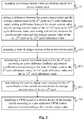
- Fig. 1 is a schematic flowchart of a heating control method according to some embodiments of the present invention. As shown in Fig. 1 , the heating control method includes steps 101 to 103.
- step 101 an average current value in a heating circuit of a power battery pack is acquired.
- the average current value refers to an average value of current sampling values over a period of time. By using calculation of an average current value, it is possible to avoid influence of instantaneous fluctuation of current on control accuracy.
- a current output value required for n th cycle is calculated according to an average current value of the n th cycle, an average current value of (n-1) th cycle, an average current value of (n-2) th cycle and a preset current value, wherein n is equal to or greater than 3.
- a Pulse width Modulation (PWM) signal is outputted to a switch device of the heating circuit according to a pre-calibrated PWM control parameter corresponding to the current output value so that a difference between an actual current value in the heating circuit and the preset current value is less than a preset threshold.
- PWM Pulse width Modulation
- switching frequency of an IGBT in a heating circuit for a power battery pack is generally in a range of 100 Hz to 1000 Hz. If frequency for the PWM signal is 1000 Hz and its duty cycle is 50%, it means that discharge process in the heating circuit takes 500 ⁇ s, and charging process take also 500 ⁇ s.
- current in the heating circuit may be sampled in real time by an Analog-to-Digital Converter (ADC) based on a 10 ⁇ s interrupt scheme, and data sampled in real-time may be uploaded to a control system through a Controller Area Network (CAN) message.
- ADC Analog-to-Digital Converter
- CAN Controller Area Network
- An average value of 50 sampled data is taken as an average current value within 500 ⁇ s for subsequent calculation to filter out influence of instantaneous fluctuation of the current on its control accuracy.
- an average current value in the n th cycle, an average current value in the (n-1) th cycle, an average current value in the (n-2) th cycle and a preset current value can be used to obtain a current output value for the n th cycle.
- a PWM signal is outputted to a switching device of the heating circuit according to a pre-calibrated PWM control parameter corresponding to the current output value so that a difference between an actual current value in the heating circuit and the preset current value is less than a preset threshold.
- the preset threshold herein is an extremely small value such that actual current value of the heating circuit is infinitely close to the preset current value.
- the heating control method of embodiments of the present invention has a higher control accuracy as compared with that in related art where current in the heating circuit is indirectly controlled by controlling IGBT's operation by way of an internal resistance of the power battery pack, and can achieve rapid heating of the battery under safety and reliability.
- Fig. 2 is a schematic flowchart of a heating control method according to some embodiments of the present invention.
- Fig. 2 differs from Fig. 1 in that step 102 in Fig. 1 can be subdivided into step 1021 to step 1024 in Fig 2 .
- a difference between the preset current value and the average current value of the n th cycle is set as n th cycle difference value
- a difference between the preset current value and the average current value of the (n-1) th cycle is set as (n-1) th cycle difference value
- a difference between the preset current value and the average current value of the (n-2) th cycle is set as (n-2) th cycle difference value.
- step 1022 a state of charge section of the power battery pack is acquired.
- a current increment required for the n th cycle is determined according to a pre-calibrated feedback adjustment coefficient corresponding to the state of charge section, the n th cycle difference value, (n-1) th cycle difference value and the (n-2) th cycle difference value.
- step 1024 the current output value required for the n th cycle is determined based on the current increment and the average current value of the (n-1) th cycle.
- the feedback adjustment coefficient refers to a parameter for correcting an output current based on a feedback current value (such as an average current value of the n th cycle, an average current value of the (n-1) th cycle, and an average current value of the (n-2) th cycle) in a certain operation situation.
- the feedback adjustment coefficient may include a proportional adjustment coefficient K p , an integral adjustment coefficient K i , and a differential adjustment coefficient K d .
- a feedback adjustment mode based on K p , K i , and K d is also referred to as a PID adjustment mode.
- step 1023 it may be also required to determine relationship between state of charge sections of the power battery pack and feedback adjustment coefficients before step 1023.
- state of charge of the power battery pack may be divided into a plurality of sections from high to low. Each state of charge section may be equal or unequal. Then, a value of the feedback adjustment coefficient matched with each state of charge section is determined. By doing so, it is possible to avoid influence of the state of charge of the power battery pack on current control accuracy in the heating process, and thus to improve the current control accuracy.
- value of K p is gradually increased from 0 until change rate of the average current value is greater than a first threshold determined based on a proportional adjustment coefficient, so as to determine relationship between the state of charge section and the proportional adjustment coefficient.
- value of K i is gradually increased from 0 until fluctuation magnitude of the average current value is greater than a second threshold determined based on an integral adjustment coefficient, so as to determine relationship between the state of charge section and the integral adjustment coefficient.
- value of K d is gradually increased from 0 until fluctuation magnitude of the average current value is greater than a third threshold determined based on a differential adjustment coefficient, so as to determine the relationship between the state of charge section and the differential adjustment coefficient.
- K p , K i and K d may be independent of each other, or may be combined with each other.
- calibration of K i or K d may be on a basis of calibrated K p
- calibration of K d may be on a basis of calibrated K p and K i .
- the second threshold and the third threshold may be equal or not equal, which depends on actual condition of the current in the heating circuit.
- the following example illustrates calibration process for K p , K i , and K d .
- S1 Material and total capacity of the power battery pack is determined, and State of Charge (SOC) of the power battery pack is initialized to 100%.
- SOC State of Charge
- K i and K d are set to be 0. That is, for calibration of the proportional adjustment coefficient, the value of K p value is gradually increased from 0 in the absence of integral control and differential control. It is determined whether a change rate of the average current value meets a requirement (the change rate is greater than the above-mentioned first threshold). When the change rate satisfies the requirement, increasing of the value of K p value is stopped. The value of K p at this point is decreased by 10% in order to increase capability of fault tolerance of K p .
- K i is gradually increased from 0 until fluctuation of the average current value satisfies a requirement. (the fluctuation amplitude is larger than the above-mentioned second threshold). The value of K i at this point is decreased by 10% in order to increase capability of fault tolerance of K i .
- K d is gradually increased from 0 until fluctuation of the average current value satisfies a requirement (the fluctuation amplitude is greater than the above-mentioned third threshold), increasing of the value of K d is stopped.
- the value of K d at this point is decreased by 10% in order to increase capability of fault tolerance of K d .
- S5. S2 to S4 are repeated each when the power battery pack is discharged by m% for further calibration until the power battery pack is discharged to 10%.
- K p , K i , and K d suitable for each state of charge section are calibrated, it is possible to avoid influence of the state of charge of the power battery pack on current control accuracy in the heating process, and thus to improve the current control accuracy.
- the inventor of the present application finds that under the premise that the state of charge of the power battery pack remains unchanged during the heating process of the power battery pack, it requires only a PWM signal is outputted at a constant period and a duty cycle to keep the output current value constant. For example, when the SOC is in a range of 80%-100% and if the PWM period is a constant value in a range of 10ms to 20ms and the duty cycle is a constant value in a range of 40% to 50%, the average output current is about a constant value within 150A-170A.
- PWM control parameter may include PWM period and duty cycle.
- a method for calibrating the PWM control parameter may include: for each state of charge section, continuously adjusting value of the PWM control parameter, and determining a value of the PWM control parameter when the average current value of the heating circuit reaches to be constant as a PWM control parameter corresponding to the current output value.
- S1 Material and total capacity of the power battery pack is determined, and State of Charge (SOC) of the power battery pack is initialized to 100%.
- SOC State of Charge
- PWM period and duty cycle are adjusted until the average current value in the heating circuit reaches a current value that is 0.8 times a maximum current limit value.
- the maximum current limit value may be varied according to the SOC value.
- S2 to S4 are repeated each when the power battery pack is discharged by m% for further calibration until the power battery pack is discharged to 10%.
- I k I k ⁇ 1 + K p e k ⁇ e k ⁇ 1 + K i e k + K d e k ⁇ 2 e k ⁇ 1 + e k ⁇ 2
- S1 current value in the heating circuit is sampled by a heating control module (e.g. a heating control chip, HCM) in real time, and average current value I(k-1), average current error values (e(k), e(k-1) and e(k-2)) corresponding to respective k th , (k-1) th , (k-2) th cycles are calculated.
- a heating control module e.g. a heating control chip, HCM
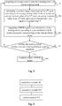
- Fig. 3 is a schematic flowchart of a heating control method according to some embodiments of the present invention.
- Fig. 3 differs from Fig. 1 in that, prior to step 101 in Fig. 1 , the heating control method in Fig. 3 further includes steps 104 to 106 for describing a startup strategy of the heating control method.
- step 104 in the case that the power battery pack has a demand of being heated, power requirement for the power battery pack being heated from a temperature at the n th cycle to a target temperature is acquired.
- step 105 it is determined whether the state of charge of the power battery pack meets the power requirement. If the state of charge of the power battery pack meets the power requirement, step 101 is performed; otherwise, step 106 is performed.
- a charging prompt signal is sent to a battery management system (BMS) of the power battery pack in order to charge the power battery pack until the state of charge of the power battery pack meets the power requirement.
- BMS battery management system
- Fig. 4 is a schematic flowchart of a heating control method according to some embodiments of the present invention.
- Fig. 4 differs from Fig. 1 in that, after step 103 in Fig. 1 , the heating control method in Fig. 4 further includes step 107 and step 108 for describing a stopping strategy of the heating control method.
- step 107 it is determined whether the heating circuit satisfies any one of predetermined stopping conditions. If the heating circuit satisfies any one of the predetermined stopping conditions, step 108 is performed; otherwise, step 101 is returned.
- step 108 output of the PWM signal is stopped.
- the predetermined stopping condition may include: the average current value in the heating circuit is greater than an allowable current threshold (e.g., 80% of a fuse blown value), any cell in the power battery pack has a temperature and voltage greater than an allowable operating range, and temperature of the power battery pack reaches the target temperature.
- an allowable current threshold e.g., 80% of a fuse blown value
- the predetermined stopping condition may further include: surface temperature of the IGBT is greater than a set threshold T set .
- the predetermined stopping condition may further include: temperature and voltage of any one of the battery cells sent by the BMS is out of the required heating range or is an invalid value.
- Fig. 5 is a schematic structural diagram of a heating control device according to some embodiments of the present invention. As shown in Fig. 5 , the heating control device includes an acquisition module 501, a calculation module 502, and a control module 503.
- the acquisition module 501 is configured to obtain an average current value in a heating circuit of a power battery pack.
- the calculation module 502 is configured to calculate a current output value required for n th cycle according to an average current value of the n th cycle, an average current value of (n-1) th cycle, an average current value of (n-2) th cycle and a preset current value, n is equal to or greater than 3.
- the control module 503 is configured to output a Pulse width Modulation (PWM) signal to a switch device of the heating circuit according to a pre-calibrated PWM control parameter corresponding to the current output value so that a difference between an actual current value in the heating circuit and the preset current value is less than a preset threshold.
- PWM Pulse width Modulation
- the heating control device further includes a calibration module configured to: for each state of charge section, continuously adjust value of the PWM control parameter, and determine a value of the PWM control parameter when the average current value of the heating circuit reaches to be constant as a PWM control parameter corresponding to the current output value.
- the embodiments of the present invention further provides a heating control device comprising a memory and a processor, wherein the memory is configured to store executable program codes, and the processor is configured to read the executable program codes stored in the memory to perform the above described heating control method.
- the functional blocks shown in the block diagrams described above may be implemented as hardware, software, firmware, or a combination thereof.
- it may be, for example, an electronic circuit, an application specific integrated circuit (ASIC), suitable firmware, plug-ins, function cards, and the like.
- ASIC application specific integrated circuit
- the elements of an embodiment of the present invention are programs or code segments that are used to perform the required tasks.
- Programs or code segments may be stored on a machine-readable medium or transmitted over a transmission medium or communication link via a data signal carried in a carrier wave.
- the "machine-readable medium” may include any medium that is capable of storing or transmitting information.
- machine-readable media examples include electronic circuitry, semiconductor memory devices, ROMs, flash memory, erasable ROM (EROM), floppy disks, CD-ROMs, optical disks, hard disks, fiber optic media, radio frequency (RF) links, and the like.
- the code segments may be downloaded via a computer network such as the Internet, an intranet or the like.
Landscapes
- Engineering & Computer Science (AREA)
- Manufacturing & Machinery (AREA)
- Chemical & Material Sciences (AREA)
- Chemical Kinetics & Catalysis (AREA)
- Electrochemistry (AREA)
- General Chemical & Material Sciences (AREA)
- Physics & Mathematics (AREA)
- Algebra (AREA)
- General Physics & Mathematics (AREA)
- Mathematical Analysis (AREA)
- Mathematical Optimization (AREA)
- Pure & Applied Mathematics (AREA)
- Automation & Control Theory (AREA)
- Secondary Cells (AREA)
- Microelectronics & Electronic Packaging (AREA)
- Electromagnetism (AREA)
- Charge And Discharge Circuits For Batteries Or The Like (AREA)
Abstract
Description
- The invention relates to the technical field of battery, and in particular, to a heating control method and a heating control device
- When a power battery pack has a temperature lower than a lower limit of an allowable operating temperature range, the power battery pack cannot work and needs to be heated to a temperature within the allowable operating temperature range before it resumes its operations.
- At present, a method for heating a power battery pack includes: controlling a switch device to instantaneously short a power battery to form a heating circuit, such that an internal resistance of the power battery generates heat when a large current generated by instantaneous shorting flows through the internal resistance, thereby heating the power battery. This solution has advantages of high heating speed and even heating. Commonly used switch devices include Insulated Gate Bipolar Transistors (IGBTs).
- However, inventors of the application have found that IGBT's operations are controlled mainly by way of internal resistances of the power battery pack in related art, but such method can only indirectly adjust heating current in the heating circuit and has lower control accuracy.
- Embodiments of the invention provide a heating control method and a heating control device that can improve accuracy of controlling current in a heating circuit of a battery pack.
- According to an aspect of the invention, there is provided a heating control method. The method includes: acquiring an average current value in a heating circuit of a power battery pack; calculating a current output value required for nth cycle according to an average current value of the nth cycle, an average current value of (n-1)th cycle, an average current value of (n-2)th cycle and a preset current value, n is equal to or greater than 3; and outputting a Pulse width Modulation (PWM) signal to a switch device of the heating circuit according to a pre-calibrated PWM control parameter corresponding to the current output value so that a difference between an actual current value in the heating circuit and the preset current value is less than a preset threshold.
- In a possible implementation of the first aspect, the calculating a current output value required for nth cycle according to an average current value of the nth cycle, an average current value of (n-1)th cycle, an average current value of (n-2)th cycle and a preset current value may include: setting a difference between the preset current value and the average current value of the nth cycle as nth cycle difference value, setting a difference between the preset current value and the average current value of the (n-1)th cycle as (n-1)th cycle difference value, and setting a difference between the preset current value and the average current value of the (n-2)th cycle as (n-2)th cycle difference value; acquiring a state of charge section of the power battery pack; determining a current increment required for the nth cycle according to a pre-calibrated feedback adjustment coefficient corresponding to the state of charge section, the nth cycle difference value, the (n-1)th cycle difference value and the (n-2)th cycle difference value; determining the current output value required for the nth cycle based on the current increment and the average current value of the (n-1)th cycle.
- In a possible implementation of the first aspect, before the determining a current increment required for the nth cycle according to a pre-calibrated feedback adjustment coefficient corresponding to the state of charge section, the nth cycle difference value, the (n-1)th cycle difference value and the (n-2)th cycle difference value, the method may further include: determining relationship between state of charge sections of the power battery pack and feedback adjustment coefficients.
- In a possible implementation of the first aspect, the feedback adjustment coefficient may include a proportional adjustment coefficient, an integral adjustment coefficient and a differential adjustment coefficient. The determining relationship between state of charge sections of the power battery pack and feedback adjustment coefficients may include: for each state of charge section, gradually increasing the proportional adjustment coefficient from 0 until change rate of the average current value is greater than a first threshold determined based on a proportional adjustment coefficient, and determining relationship between the state of charge section and the proportional adjustment coefficient; for each state of charge section, gradually increasing the integral adjustment coefficient from 0 until fluctuation magnitude of the average current value is greater than a second threshold determined based on an integral adjustment coefficient, and determining relationship between the state of charge section and the integral adjustment coefficient; for each state of charge section, gradually increasing the differential adjustment coefficient from 0 until fluctuation magnitude of the average current value is greater than a third threshold determined based on a differential adjustment coefficient, and determining relationship between the state of charge section and the differential adjustment coefficient.
- In a possible implementation of the first aspect, before the outputting a Pulse width Modulation (PWM) signal to a switch device of the heating circuit according to a pre-calibrated PWM control parameter corresponding to the current output value, the method may further include: for each state of charge section, continuously adjusting value of the PWM control parameter; and determining a value of the PWM control parameter when the average current value of the heating circuit reaches to be constant as a PWM control parameter corresponding to the current output value.
- In a possible implementation of the first aspect, before the acquiring an average current value in a heating circuit of a power battery pack, the method may further include: acquiring, in the case that the power battery pack has a demand of being heated, power requirement for the power battery pack being heated from a temperature at the nth cycle to a target temperature; determining whether the state of charge of the power battery pack meets the power requirement; obtaining the average current value in the heating circuit of the power battery pack if the state of charge of the power battery pack meets the power requirement.
- In a possible implementation of the first aspect, after the determining whether the state of charge of the power battery pack meets the power requirement, the method may further include: sending a charging prompt signal to a battery management system (BMS) of the power battery pack if the state of charge of the power battery pack does not meet the power requirement in order to charge the power battery pack until the state of charge of the power battery pack meets the power requirement.
- In a possible implementation of the first aspect, after the outputting a Pulse width Modulation (PWM) signal to a switch device of the heating circuit according to a pre-calibrated PWM control parameter corresponding to the current output value, the method may further include: stopping outputting the PWM signal if the heating circuit satisfies any one of predetermined stopping conditions, the predetermined stopping conditions including: the average current value in the heating circuit is greater than an allowable current threshold, any cell in the power battery pack has a temperature and voltage greater than an allowable operating range, and temperature of the power battery pack reaches the target temperature.
- According to a second aspect of embodiments of the invention, there is provided a heating control device. The heating control device includes: an acquisition module configured to acquiring an average current value in a heating circuit of a power battery pack; a calculation module configured to calculate a current output value required for nth cycle according to an average current value of the nth cycle, an average current value of (n-1)th cycle, an average current value of (n-2)th cycle and a preset current value, n is equal to or greater than 3; a control module configured to output a Pulse width Modulation (PWM) signal to a switch device of the heating circuit according to a pre-calibrated PWM control parameter corresponding to the current output value so that a difference between an actual current value in the heating circuit and the preset current value is less than a preset threshold.
- In a possible implementation of the second aspect, the heating control device may further include: a determination module configured to: for each state of charge section, continuously adjust value of the PWM control parameter, and determine a value of the PWM control parameter when the average current value of the heating circuit reaches to be constant as a PWM control parameter corresponding to the current output value.
- According to a third aspect of embodiments of the invention, there is provided a heating control device. The heating control device includes: a memory and a processor. The memory is configured to store executable program codes. The processor is configured to read the executable program codes stored in the memory to perform a heating control method according to embodiments of the present invention.
- As described above, when current in the heating circuit needs to be controlled in the current cycle (for example, the nth cycle), an average current value in the nth cycle, an average current value in the (n-1)th cycle, an average current value in the (n-2)th cycle and a preset current value can be used to acquiring a current output value for the nth cycle. After that, a PWM signal is outputted to a switching device of the heating circuit according to a pre-calibrated PWM control parameter corresponding to the current output value so that a difference between an actual current value in the heating circuit and the preset current value is less than a preset threshold. The preset threshold herein is an extremely small value such that actual current value of the heating circuit is infinitely close to the preset current value.
- Since it is possible for embodiments of the present invention to directly control current in the heating circuit based on feedback current values in the heating circuit (for example, the average current value of the nth cycle, the average current value of the (n-1)th cycle, the average current value of the (n-2)th cycle) and a preset current value, the heating control method of embodiments of the present invention has a higher control accuracy as compared with that in related art where current in the heating circuit is indirectly controlled by controlling IGBT's operation by way of an internal resistance of the power battery pack, and can thus achieve rapid heating of the battery under safety and reliability.
- The invention may be better understood from the following descriptions of specific embodiments of the present invention taken in conjunction with the accompanying drawings, in which the same or similar reference numerals represent the same or similar features.
-
Fig. 1 is a schematic flowchart of a heating control method according to some embodiments of the present invention; -
Fig.2 is a schematic flowchart of a heating control method according to some embodiments of the present invention; -
Fig. 3 is a schematic flowchart of a heating control method according to some embodiments of the present invention -
Fig.4 is a schematic flowchart of a heating control method according to some embodiments of the present invention; -
Fig. 5 is a schematic structural diagram of a heating control device according to some embodiments of the present invention. - Features and exemplary embodiments of various aspects of the invention are described in detail below. In the following detailed descriptions, numerous specific details are set forth in order to provide a thorough understanding of the present invention.
- The embodiments of the present invention provide a heating control method and a heating control device for controlling current in a heating circuit of a power battery pack, which has a higher control accuracy and can achieve rapid heating of the battery under safety and reliability.
- From a scale, a power battery pack consists of at least two battery cells in series and/or in parallel. The battery cell in embodiments of the present invention may be a lithium ion battery, a lithium metal battery, a lead-acid battery, a nickel-interval battery, a nickel-hydrogen battery, a lithium-sulfur battery, a lithium air battery, or a sodium ion battery, which is not limited herein.
-
Fig. 1 is a schematic flowchart of a heating control method according to some embodiments of the present invention. As shown inFig. 1 , the heating control method includessteps 101 to 103. - In
step 101, an average current value in a heating circuit of a power battery pack is acquired. - The average current value refers to an average value of current sampling values over a period of time. By using calculation of an average current value, it is possible to avoid influence of instantaneous fluctuation of current on control accuracy.
- In
step 102, a current output value required for nth cycle is calculated according to an average current value of the nth cycle, an average current value of (n-1)th cycle, an average current value of (n-2)th cycle and a preset current value, wherein n is equal to or greater than 3. - In
step 103, a Pulse width Modulation (PWM) signal is outputted to a switch device of the heating circuit according to a pre-calibrated PWM control parameter corresponding to the current output value so that a difference between an actual current value in the heating circuit and the preset current value is less than a preset threshold. - In general, switching frequency of an IGBT in a heating circuit for a power battery pack is generally in a range of 100 Hz to 1000 Hz. If frequency for the PWM signal is 1000 Hz and its duty cycle is 50%, it means that discharge process in the heating circuit takes 500 µs, and charging process take also 500 µs.
- In some embodiments, current in the heating circuit may be sampled in real time by an Analog-to-Digital Converter (ADC) based on a 10µs interrupt scheme, and data sampled in real-time may be uploaded to a control system through a Controller Area Network (CAN) message. An average value of 50 sampled data is taken as an average current value within 500µs for subsequent calculation to filter out influence of instantaneous fluctuation of the current on its control accuracy.
- As described above, when current in the heating circuit needs to be controlled in the current cycle (for example, the nth cycle), an average current value in the nth cycle, an average current value in the (n-1)th cycle, an average current value in the (n-2)th cycle and a preset current value can be used to obtain a current output value for the nth cycle. After that, a PWM signal is outputted to a switching device of the heating circuit according to a pre-calibrated PWM control parameter corresponding to the current output value so that a difference between an actual current value in the heating circuit and the preset current value is less than a preset threshold. The preset threshold herein is an extremely small value such that actual current value of the heating circuit is infinitely close to the preset current value.
- Since it is possible for embodiments of the present invention to directly control current in the heating circuit based on feedback current values in the heating circuit (for example, the average current value of the nth cycle, the average current value of the (n-1)th cycle, the average current value of the (n-2)th cycle) and a preset current value, the heating control method of embodiments of the present invention has a higher control accuracy as compared with that in related art where current in the heating circuit is indirectly controlled by controlling IGBT's operation by way of an internal resistance of the power battery pack, and can achieve rapid heating of the battery under safety and reliability.
-
Fig. 2 is a schematic flowchart of a heating control method according to some embodiments of the present invention.Fig. 2 differs fromFig. 1 in thatstep 102 inFig. 1 can be subdivided into step 1021 to step 1024 inFig 2 . - In step 1021, a difference between the preset current value and the average current value of the nth cycle is set as nth cycle difference value, a difference between the preset current value and the average current value of the (n-1)th cycle is set as (n-1)th cycle difference value, and a difference between the preset current value and the average current value of the (n-2)th cycle is set as (n-2)th cycle difference value.
- In
step 1022, a state of charge section of the power battery pack is acquired. - In step 1023, a current increment required for the nth cycle is determined according to a pre-calibrated feedback adjustment coefficient corresponding to the state of charge section, the nth cycle difference value, (n-1)th cycle difference value and the (n-2)th cycle difference value.
- In step 1024, the current output value required for the nth cycle is determined based on the current increment and the average current value of the (n-1)th cycle.
- The feedback adjustment coefficient refers to a parameter for correcting an output current based on a feedback current value (such as an average current value of the nth cycle, an average current value of the (n-1)th cycle, and an average current value of the (n-2)th cycle) in a certain operation situation.
- In some embodiments, the feedback adjustment coefficient may include a proportional adjustment coefficient Kp, an integral adjustment coefficient Ki, and a differential adjustment coefficient Kd. A feedback adjustment mode based on Kp, Ki, and Kd is also referred to as a PID adjustment mode.
- In embodiments of the present invention, it may be also required to determine relationship between state of charge sections of the power battery pack and feedback adjustment coefficients before step 1023.
- Specifically, state of charge of the power battery pack may be divided into a plurality of sections from high to low. Each state of charge section may be equal or unequal. Then, a value of the feedback adjustment coefficient matched with each state of charge section is determined. By doing so, it is possible to avoid influence of the state of charge of the power battery pack on current control accuracy in the heating process, and thus to improve the current control accuracy.
- In some embodiments, for calibration of Kp, value of Kp is gradually increased from 0 until change rate of the average current value is greater than a first threshold determined based on a proportional adjustment coefficient, so as to determine relationship between the state of charge section and the proportional adjustment coefficient.
- In some embodiments, for calibration of Ki, value of Ki is gradually increased from 0 until fluctuation magnitude of the average current value is greater than a second threshold determined based on an integral adjustment coefficient, so as to determine relationship between the state of charge section and the integral adjustment coefficient.
- In some embodiments, for calibration of Kd, value of Kd is gradually increased from 0 until fluctuation magnitude of the average current value is greater than a third threshold determined based on a differential adjustment coefficient, so as to determine the relationship between the state of charge section and the differential adjustment coefficient.
- It should be noted that the above calibration processes for Kp, Ki and Kd may be independent of each other, or may be combined with each other. For example, calibration of Ki or Kd may be on a basis of calibrated Kp, or calibration of Kd may be on a basis of calibrated Kp and Ki. Here, the second threshold and the third threshold may be equal or not equal, which depends on actual condition of the current in the heating circuit.
- The following example illustrates calibration process for Kp, Ki, and Kd.
- S1. Material and total capacity of the power battery pack is determined, and State of Charge (SOC) of the power battery pack is initialized to 100%.
- S2. Ki and Kd are set to be 0. That is, for calibration of the proportional adjustment coefficient, the value of Kp value is gradually increased from 0 in the absence of integral control and differential control. It is determined whether a change rate of the average current value meets a requirement (the change rate is greater than the above-mentioned first threshold). When the change rate satisfies the requirement, increasing of the value of Kp value is stopped. The value of Kp at this point is decreased by 10% in order to increase capability of fault tolerance of Kp.
- S3. Value of Ki is gradually increased from 0 until fluctuation of the average current value satisfies a requirement. (the fluctuation amplitude is larger than the above-mentioned second threshold). The value of Ki at this point is decreased by 10% in order to increase capability of fault tolerance of Ki.
- S4. Value of Kd is gradually increased from 0 until fluctuation of the average current value satisfies a requirement (the fluctuation amplitude is greater than the above-mentioned third threshold), increasing of the value of Kd is stopped. The value of Kd at this point is decreased by 10% in order to increase capability of fault tolerance of Kd.
- S5. S2 to S4 are repeated each when the power battery pack is discharged by m% for further calibration until the power battery pack is discharged to 10%.
- After the above five steps, a two-dimensional array of ((100-10)/m)*3 is obtained for storing Kp, Ki, and Kd values corresponding to different SOCs, wherein m represents a preset width of a divided state of charge section.
- In embodiments of the present invention, since Kp, Ki, and Kd suitable for each state of charge section are calibrated, it is possible to avoid influence of the state of charge of the power battery pack on current control accuracy in the heating process, and thus to improve the current control accuracy.
- According to the closed-loop strategy in embodiments of the present invention, the inventor of the present application finds that under the premise that the state of charge of the power battery pack remains unchanged during the heating process of the power battery pack, it requires only a PWM signal is outputted at a constant period and a duty cycle to keep the output current value constant. For example, when the SOC is in a range of 80%-100% and if the PWM period is a constant value in a range of 10ms to 20ms and the duty cycle is a constant value in a range of 40% to 50%, the average output current is about a constant value within 150A-170A.
- In some embodiments, it is possible to calibrate relationship between output current values and PWM control parameters in advance. PWM control parameter may include PWM period and duty cycle.
- A method for calibrating the PWM control parameter may include: for each state of charge section, continuously adjusting value of the PWM control parameter, and determining a value of the PWM control parameter when the average current value of the heating circuit reaches to be constant as a PWM control parameter corresponding to the current output value.
- The following example illustrates calibration process of PWM control parameters in detail.
- S1. Material and total capacity of the power battery pack is determined, and State of Charge (SOC) of the power battery pack is initialized to 100%.
- S2. PWM period and duty cycle are adjusted until the average current value in the heating circuit reaches a current value that is 0.8 times a maximum current limit value.
- The maximum current limit value may be varied according to the SOC value.
- S3. Respective PWM period and duty cycle are recorded.
- S4. S2 to S4 are repeated each when the power battery pack is discharged by m% for further calibration until the power battery pack is discharged to 10%.
- After the above four steps, respective period and duty cycle when the power battery pack is in different state of charge sections can be obtained.
- A current control strategy for PID dynamic adjustment based on Kp, Ki, and Kd in a heating circuit is described in detail with the expressions (1)-(4) below.
- The proportional-integral-derivative control expression is as follows:


- Assuming that a sampling interval for the average current value in the heating circuit is T, and a difference between an average current value for kth cycle and a preset current value is taken as an average current deviation e(k) of the cycle, then:
- the integral deviation at time point K is: e(k) + e(k-1)+ e(k-2) +... + e(0);
- the derivative deviation at time point K is: (e(k)-e(k-1))/T;
- Discretization of expression (1) yields:


- According to the expression (2), a proportional-integral-derivative control expression of the discretized sampling current of each of the kth cycle and the (k-1)th cycle can be obtained.
- Further, the proportional-integral-derivative control expressions of discretized sampling current of the kth cycle and the (k-1)th cycle are subtracted to obtain a current increment between the kth cycle and the (k-1)th cycle, Δi(k):

- With expression (3), the average current value I(k) that needs to be outputted during the kth cycle can be obtained as:

- The following is a detailed description of the current control process for PID dynamic adjustment based on Kp, Ki, and Kd in a heating circuit in conjunction with expressions (1)-(4).
- S1: current value in the heating circuit is sampled by a heating control module (e.g. a heating control chip, HCM) in real time, and average current value I(k-1), average current error values (e(k), e(k-1) and e(k-2)) corresponding to respective kth, (k-1)th, (k-2)th cycles are calculated.
- S2: according to a state of charge section of the power battery pack sent by the BMS, respective Kp, Ki and Kd values are acquired from the two-dimensional array obtained by calibration of the feedback adjustment coefficient.
- S3: e(k), e(k-1), e(k-2), I(k-1) and Kp, Ki and Kd are substituted into expression (4) to obtain the average current value to be output in the kth cycle.
- S4: according to a state of charge section of the power battery pack sent by the BMS, respective PWM period and the duty cycle are acquired from the two-dimensional array obtained by calibration of the PWM control parameter, and then a PWM signal is outputted.
- Through the above steps S1-S4, it is possible to control heating such that average current can be maintained in a constant current state, and thereby quickly heating of the battery can be achieved under safety and reliability.
-
Fig. 3 is a schematic flowchart of a heating control method according to some embodiments of the present invention.Fig. 3 differs fromFig. 1 in that, prior to step 101 inFig. 1 , the heating control method inFig. 3 further includessteps 104 to 106 for describing a startup strategy of the heating control method. - In
step 104, in the case that the power battery pack has a demand of being heated, power requirement for the power battery pack being heated from a temperature at the nth cycle to a target temperature is acquired. - In
step 105, it is determined whether the state of charge of the power battery pack meets the power requirement. If the state of charge of the power battery pack meets the power requirement,step 101 is performed; otherwise,step 106 is performed. - In
step 106, a charging prompt signal is sent to a battery management system (BMS) of the power battery pack in order to charge the power battery pack until the state of charge of the power battery pack meets the power requirement. -
Fig. 4 is a schematic flowchart of a heating control method according to some embodiments of the present invention.Fig. 4 differs fromFig. 1 in that, afterstep 103 inFig. 1 , the heating control method inFig. 4 further includesstep 107 and step 108 for describing a stopping strategy of the heating control method. - In
step 107, it is determined whether the heating circuit satisfies any one of predetermined stopping conditions. If the heating circuit satisfies any one of the predetermined stopping conditions,step 108 is performed; otherwise,step 101 is returned. - In
step 108, output of the PWM signal is stopped. - In some embodiments, considering that precondition for dynamically adjusting the PWM wave for heating is that the power battery pack has normal parameters, the predetermined stopping condition may include: the average current value in the heating circuit is greater than an allowable current threshold (e.g., 80% of a fuse blown value), any cell in the power battery pack has a temperature and voltage greater than an allowable operating range, and temperature of the power battery pack reaches the target temperature.
- In some embodiments, considering that the precondition for dynamically adjusting the PWM wave for heating further includes IGBT has normal parameters, the predetermined stopping condition may further include: surface temperature of the IGBT is greater than a set threshold Tset.
- In some embodiments, considering that the precondition for dynamically adjusting the PWM wave for heating further includes communication line is in normal, the predetermined stopping condition may further include: temperature and voltage of any one of the battery cells sent by the BMS is out of the required heating range or is an invalid value.
- As described above, by detecting voltage, temperature of cells in the heating circuit, state of charge of the power battery pack and surface temperature of the IGBT, it is possible to protect the system so that a real-time, safe and reliable heating system can be guaranteed.
-
Fig. 5 is a schematic structural diagram of a heating control device according to some embodiments of the present invention. As shown inFig. 5 , the heating control device includes anacquisition module 501, acalculation module 502, and acontrol module 503. - The
acquisition module 501 is configured to obtain an average current value in a heating circuit of a power battery pack. - The
calculation module 502 is configured to calculate a current output value required for nth cycle according to an average current value of the nth cycle, an average current value of (n-1)th cycle, an average current value of (n-2)th cycle and a preset current value, n is equal to or greater than 3. - The
control module 503 is configured to output a Pulse width Modulation (PWM) signal to a switch device of the heating circuit according to a pre-calibrated PWM control parameter corresponding to the current output value so that a difference between an actual current value in the heating circuit and the preset current value is less than a preset threshold. - In some embodiments, the heating control device further includes a calibration module configured to: for each state of charge section, continuously adjust value of the PWM control parameter, and determine a value of the PWM control parameter when the average current value of the heating circuit reaches to be constant as a PWM control parameter corresponding to the current output value.
- The embodiments of the present invention further provides a heating control device comprising a memory and a processor, wherein the memory is configured to store executable program codes, and the processor is configured to read the executable program codes stored in the memory to perform the above described heating control method.
- It should be clear that the embodiments in this specification are described in a progressive manner, and the same or similar parts in each embodiment may be referred to each other, and each embodiment focuses on the difference from other embodiments. For device embodiments, relevant parts can be referred to the description of the method embodiments. The embodiments of the present invention are not limited to the specific steps and structures described above and shown in the drawings. Those skilled in the art can make various changes, modifications and additions or changing the order between steps after understanding the principals of the embodiments of the present invention. Also, for the sake of brevity, detailed descriptions of known methods and techniques are omitted here.
- The functional blocks shown in the block diagrams described above may be implemented as hardware, software, firmware, or a combination thereof. When implemented in hardware, it may be, for example, an electronic circuit, an application specific integrated circuit (ASIC), suitable firmware, plug-ins, function cards, and the like. When implemented in software, the elements of an embodiment of the present invention are programs or code segments that are used to perform the required tasks. Programs or code segments may be stored on a machine-readable medium or transmitted over a transmission medium or communication link via a data signal carried in a carrier wave. The "machine-readable medium" may include any medium that is capable of storing or transmitting information. Examples of machine-readable media include electronic circuitry, semiconductor memory devices, ROMs, flash memory, erasable ROM (EROM), floppy disks, CD-ROMs, optical disks, hard disks, fiber optic media, radio frequency (RF) links, and the like. The code segments may be downloaded via a computer network such as the Internet, an intranet or the like.
- The embodiments of the present invention may be implemented in other specific forms without departing from its scope and essential characteristics. For example, the algorithms described in the specific embodiments may be modified without system architecture departing from the basic scope of the embodiments of the present invention. As such, the embodiments are to be considered in all respects as illustrative and not restrictive, and the scope of the embodiments of the invention is defined by the appended claims rather than the foregoing descriptions. All changes that are defined in the meaning and the equivalents of the claims come within the scope of the embodiments of the invention.
Claims (12)
- A heating control method, characterized by comprising:acquiring (101) an average current value in a heating circuit of a power battery pack;calculating (102) a current output value required for nth cycle according to an average current value of the nth cycle, an average current value of (n-1)th cycle, an average current value of (n-2)th cycle and a preset current value, n is equal to or greater than 3; andoutputting (103) a Pulse width Modulation (PWM) signal to a switch device of the heating circuit according to a pre-calibrated PWM control parameter corresponding to the current output value so that a difference between an actual current value in the heating circuit and the preset current value is less than a preset threshold.
- The method according to claim 1, wherein the calculating a current output value required for nth cycle according to an average current value of the nth cycle, an average current value of (n-1)th cycle, an average current value of (n-2)th cycle and a preset current value comprises:setting (1021) a difference between the preset current value and the average current value of the nth cycle as nth cycle difference value, setting a difference between the preset current value and the average current value of the (n-1)th cycle as (n-1)th cycle difference value, and setting a difference between the preset current value and the average current value of the (n-2)th cycle as (n-2)th cycle difference value;acquiring (1022) a state of charge section of the power battery pack;determining (1023) a current increment required for the nth cycle according to a pre-calibrated feedback adjustment coefficient corresponding to the state of charge section, the nth cycle difference value, (n-1)th cycle difference value and the (n-2)th cycle difference value;determining (1024) the current output value required for the nth cycle based on the current increment and the average current value of the (n-1)th cycle.
- The method according to claim 2, wherein before the determining a current increment required for the nth cycle according to a pre-calibrated feedback adjustment coefficient corresponding to the state of charge section, the nth cycle difference value, the (n-1)th cycle difference value and the (n-2)th cycle difference value, the method further comprises:determining relationship between state of charge sections of the power battery pack and feedback adjustment coefficients.
- The method according to claim 3, wherein the feedback adjustment coefficient comprises a proportional adjustment coefficient, an integral adjustment coefficient and a differential adjustment coefficient, and the determining relationship between state of charge sections of the power battery pack and feedback adjustment coefficients comprises:for each state of charge section, gradually increasing the proportional adjustment coefficient from 0 until change rate of the average current value is greater than a first threshold determined based on a proportional adjustment coefficient, and determining relationship between the state of charge section and the proportional adjustment coefficient;for each state of charge section, gradually increasing the integral adjustment coefficient from 0 until fluctuation magnitude of the average current value is greater than a second threshold determined based on an integral adjustment coefficient, and determining relationship between the state of charge section and the integral adjustment coefficient;for each state of charge section, gradually increasing the differential adjustment coefficient from 0 until fluctuation magnitude of the average current value is greater than a third threshold determined based on a differential adjustment coefficient, and determining relationship between the state of charge section and the differential adjustment coefficient.
- The method according to claim 1, wherein before the outputting a Pulse width Modulation (PWM) signal to a switch device of the heating circuit according to a pre-calibrated PWM control parameter corresponding to the current output value, the method further comprises:for each state of charge section,continuously adjusting value of the PWM control parameter; anddetermining a value of the PWM control parameter when the average current value of the heating circuit reaches to be constant as a PWM control parameter corresponding to the current output value.
- The method according to claim 1, wherein before the acquiring an average current value in a heating circuit of a power battery pack, the method further comprises:acquiring (104), in the case that the power battery pack has a demand of being heated, power requirement for the power battery pack being heated from a temperature at the nth cycle to a target temperature;determining (105) whether the state of charge of the power battery pack meets the power requirement;obtaining (101) the average current value in the heating circuit of the power battery pack if the state of charge of the power battery pack meets the power requirement.
- The method according to claim 6, wherein after the determining whether the state of charge of the power battery pack meets the power requirement, the method further comprises:sending (106) a charging prompt signal to a battery management system (BMS) of the power battery pack if the state of charge of the power battery pack does not meet the power requirement in order to charge the power battery pack until the state of charge of the power battery pack meets the power requirement.
- The method according to claim 1, wherein after the outputting a Pulse width Modulation (PWM) signal to a switch device of the heating circuit according to a pre-calibrated PWM control parameter corresponding to the current output value, the method further comprises:stopping (108) outputting the PWM signal if the heating circuit satisfies any one of predetermined stopping conditions including: the average current value in the heating circuit is greater than an allowable current threshold, any cell in the power battery pack has a temperature and voltage greater than an allowable operating range, and temperature of the power battery pack reaches the target temperature.
- A heating control device, characterized by comprising:an acquisition module configured to acquire an average current value in a heating circuit of a power battery pack;a calculation module configured to calculate a current output value required for nth cycle according to an average current value of the nth cycle, an average current value of (n-1)th cycle, an average current value of (n-2)th cycle and a preset current value, n is equal to or greater than 3;a control module configured to output a Pulse width Modulation (PWM) signal to a switch device of the heating circuit according to a pre-calibrated PWM control parameter corresponding to the current output value so that a difference between an actual current value in the heating circuit and the preset current value is less than a preset threshold.
- The heating control device according to claim 9, further comprising:a calibration module configured to: for each state of charge section, continuously adjust value of the PWM control parameter, and determine a value of the PWM control parameter when the average current value of the heating circuit reaches to be constant as a PWM control parameter corresponding to the current output value.
- The heating control device according to claim 9, further comprising a memory and a processor,
the memory is configured to store executable program codes; and
the processor is configured to read the executable program codes stored in the memory to function as the modules according to any one of claims 9 to 10. - A computer-readable storage medium having stored thereon computer instructions that, when executed by a processor, cause the processor to implement steps of the method according to any one of claims 1-8.
Applications Claiming Priority (1)
| Application Number | Priority Date | Filing Date | Title |
|---|---|---|---|
| CN201810495990.9A CN108736108B (en) | 2018-05-22 | 2018-05-22 | Heating control method and heating control device |
Publications (2)
| Publication Number | Publication Date |
|---|---|
| EP3573172A1 true EP3573172A1 (en) | 2019-11-27 |
| EP3573172B1 EP3573172B1 (en) | 2020-09-23 |
Family
ID=63937787
Family Applications (1)
| Application Number | Title | Priority Date | Filing Date |
|---|---|---|---|
| EP19150225.1A Active EP3573172B1 (en) | 2018-05-22 | 2019-01-03 | Heating control method and heating control device |
Country Status (3)
| Country | Link |
|---|---|
| US (1) | US11309598B2 (en) |
| EP (1) | EP3573172B1 (en) |
| CN (1) | CN108736108B (en) |
Cited By (6)
| Publication number | Priority date | Publication date | Assignee | Title |
|---|---|---|---|---|
| CN111430845A (en) * | 2020-03-20 | 2020-07-17 | 威睿电动汽车技术(宁波)有限公司 | A battery pack thermal management method, device, storage medium and electronic device |
| CN115078802A (en) * | 2022-05-25 | 2022-09-20 | 一汽解放汽车有限公司 | Method and device for acquiring loading energy of hybrid vehicle and computer equipment |
| CN115903948A (en) * | 2022-11-04 | 2023-04-04 | 广州华凌制冷设备有限公司 | Protection and control method, device, frequency conversion controller, and storage medium for power devices |
| CN116036481A (en) * | 2022-12-27 | 2023-05-02 | 广东花至美容科技有限公司 | Beauty instrument control method, storage medium and electronic device |
| CN117080624A (en) * | 2023-09-13 | 2023-11-17 | 苏州华骞时代新能源科技有限公司 | A battery heating control method and system |
| CN120049579A (en) * | 2025-04-24 | 2025-05-27 | 深圳市乌托邦创意科技有限公司 | Low-energy-loss use method and device of mobile power supply |
Families Citing this family (22)
| Publication number | Priority date | Publication date | Assignee | Title |
|---|---|---|---|---|
| CN111216600B (en) * | 2018-11-27 | 2024-04-16 | 中信国安盟固利动力科技有限公司 | A battery system with adjustable heating speed and control method thereof |
| CN111347935B (en) * | 2018-12-21 | 2021-10-22 | 比亚迪股份有限公司 | A vehicle and its power battery heating device and method |
| CN111354999B (en) * | 2018-12-21 | 2021-07-09 | 比亚迪股份有限公司 | A vehicle and its power battery heating device and method |
| KR102699008B1 (en) | 2019-08-30 | 2024-08-26 | 현대자동차주식회사 | System and method for increasing temperature of battery |
| CN110850721B (en) * | 2019-12-02 | 2023-02-07 | 合肥工业大学 | A current adaptive calibration control method, system and electronic equipment |
| CN111208861B (en) * | 2020-01-15 | 2022-01-18 | 重庆超力电器有限责任公司 | PTC power control method and device |
| WO2021223172A1 (en) * | 2020-05-07 | 2021-11-11 | 深圳市大疆创新科技有限公司 | Power supply circuit, power source apparatus, mobile platform, and method for adjusting remaining electric quantity |
| CN113745700B (en) * | 2020-05-29 | 2023-08-08 | 比亚迪股份有限公司 | Heating method, device and storage medium for electric vehicle and power battery thereof |
| KR20220026970A (en) | 2020-08-26 | 2022-03-07 | 현대자동차주식회사 | System and method for increasing temperature of battery |
| CN112151914B (en) * | 2020-09-15 | 2022-08-09 | 欣旺达电动汽车电池有限公司 | Alternating-current heating method and device for power battery and electric vehicle |
| KR20220089347A (en) | 2020-12-21 | 2022-06-28 | 현대자동차주식회사 | System and method for increasing temperature of battery |
| JP7418556B2 (en) * | 2021-01-28 | 2024-01-19 | 寧徳時代新能源科技股▲分▼有限公司 | Charging method, battery management system for drive battery, and charging post |
| CN112909381B (en) * | 2021-03-30 | 2025-06-06 | 深圳市吉毅创能源科技有限公司 | Battery heating circuit, controller and method |
| CN114024352B (en) * | 2021-11-16 | 2025-08-22 | 深圳市波斯曼技术有限公司 | A sodium ion battery management system for rail transit |
| CN114976368B (en) * | 2022-06-30 | 2024-09-13 | 如果新能源科技(江苏)股份有限公司 | Heating method of battery pack, battery pack and off-grid power supply system |
| CN115139829B (en) * | 2022-07-29 | 2024-06-18 | 潍柴动力股份有限公司 | A charging heating control method, device, electronic device and storage medium |
| CN115079750B (en) * | 2022-08-11 | 2023-04-25 | 中国核动力研究设计院 | Heating control method and equipment for welding equipment and computer readable storage medium |
| CN115267604B (en) * | 2022-08-23 | 2025-09-05 | 兴储世纪科技(深圳)有限公司 | A detection method for energy storage battery temperature regulation system |
| CN115395618B (en) * | 2022-09-21 | 2025-06-27 | 东集技术股份有限公司 | A lithium battery temperature control method, system, device and readable storage medium |
| CN115388955A (en) * | 2022-10-25 | 2022-11-25 | 国网浙江省电力有限公司宁波市北仑区供电公司 | Power distribution cabinet monitoring method and system |
| CN122227939A (en) * | 2024-12-10 | 2026-06-16 | 北京北方华创微电子装备有限公司 | Process chamber temperature control methods, power regulation devices and semiconductor process equipment |
| CN119325158A (en) * | 2024-12-18 | 2025-01-17 | 深圳艾为电气技术股份有限公司 | PTC heater power control method, device, equipment and medium |
Citations (4)
| Publication number | Priority date | Publication date | Assignee | Title |
|---|---|---|---|---|
| US5789092A (en) * | 1993-12-30 | 1998-08-04 | Neste Oy | Method and equipment for prevention of cooling of electrochemical devices |
| EP1026769A2 (en) * | 1999-02-03 | 2000-08-09 | Nokia Mobile Phones Ltd. | Device for reactivation of an electric battery |
| WO2016000492A1 (en) * | 2014-06-30 | 2016-01-07 | Byd Company Limited | Battery heating system, battery assembly and electric vehicle |
| CN107317066A (en) * | 2017-06-30 | 2017-11-03 | 北京新能源汽车股份有限公司 | Heating control method and system for power battery |
Family Cites Families (13)
| Publication number | Priority date | Publication date | Assignee | Title |
|---|---|---|---|---|
| US7382102B2 (en) * | 2005-06-13 | 2008-06-03 | Chrysler Llc | Heating of batteries using reactive power |
| CN100440614C (en) * | 2007-01-26 | 2008-12-03 | 清华大学 | A real-time method for estimating the temperature difference between inside and outside of Ni-MH power battery |
| US8143863B2 (en) * | 2009-10-12 | 2012-03-27 | O2Micro, Inc | Circuits and methods for controlling a current flowing through a battery |
| CN201966300U (en) * | 2010-07-30 | 2011-09-07 | 比亚迪股份有限公司 | Heating circuit of battery |
| KR101584405B1 (en) * | 2013-10-31 | 2016-01-12 | 주식회사 엘지화학 | Application module having fixed interface |
| CN107250823B (en) * | 2014-11-04 | 2020-10-30 | Cps科技控股有限公司 | Scalable Modular Design of a 48-Volt Li-Ion Battery Management System |
| JP6156353B2 (en) * | 2014-12-24 | 2017-07-05 | トヨタ自動車株式会社 | In-vehicle battery temperature increasing device and temperature increasing method |
| CN107591589B (en) * | 2016-07-08 | 2019-08-30 | 宁德时代新能源科技股份有限公司 | Battery cell heating temperature control method |
| JP6684184B2 (en) * | 2016-08-12 | 2020-04-22 | 株式会社Subaru | Battery heating controller |
| CN106785233B (en) * | 2016-12-27 | 2019-04-02 | 宁德时代新能源科技股份有限公司 | Heating control method and heating control device for battery structure and battery system |
| CN107482259A (en) * | 2017-05-27 | 2017-12-15 | 宝沃汽车(中国)有限公司 | Computational methods, device, system and the vehicle of battery heating circuit electric current |
| CN107171041B (en) * | 2017-06-12 | 2019-02-12 | 北京理工大学 | A kind of power battery alternating current variable current ladder heating method |
| CN107910617A (en) * | 2017-11-15 | 2018-04-13 | 西安蜂语信息科技有限公司 | Battery heating means, device and battery heating module |
-
2018
- 2018-05-22 CN CN201810495990.9A patent/CN108736108B/en active Active
- 2018-12-27 US US16/233,096 patent/US11309598B2/en active Active
-
2019
- 2019-01-03 EP EP19150225.1A patent/EP3573172B1/en active Active
Patent Citations (4)
| Publication number | Priority date | Publication date | Assignee | Title |
|---|---|---|---|---|
| US5789092A (en) * | 1993-12-30 | 1998-08-04 | Neste Oy | Method and equipment for prevention of cooling of electrochemical devices |
| EP1026769A2 (en) * | 1999-02-03 | 2000-08-09 | Nokia Mobile Phones Ltd. | Device for reactivation of an electric battery |
| WO2016000492A1 (en) * | 2014-06-30 | 2016-01-07 | Byd Company Limited | Battery heating system, battery assembly and electric vehicle |
| CN107317066A (en) * | 2017-06-30 | 2017-11-03 | 北京新能源汽车股份有限公司 | Heating control method and system for power battery |
Cited By (8)
| Publication number | Priority date | Publication date | Assignee | Title |
|---|---|---|---|---|
| CN111430845A (en) * | 2020-03-20 | 2020-07-17 | 威睿电动汽车技术(宁波)有限公司 | A battery pack thermal management method, device, storage medium and electronic device |
| CN111430845B (en) * | 2020-03-20 | 2023-08-11 | 浙江吉利控股集团有限公司 | A battery pack heat management method, device, storage medium and electronic equipment |
| CN115078802A (en) * | 2022-05-25 | 2022-09-20 | 一汽解放汽车有限公司 | Method and device for acquiring loading energy of hybrid vehicle and computer equipment |
| CN115903948A (en) * | 2022-11-04 | 2023-04-04 | 广州华凌制冷设备有限公司 | Protection and control method, device, frequency conversion controller, and storage medium for power devices |
| CN116036481A (en) * | 2022-12-27 | 2023-05-02 | 广东花至美容科技有限公司 | Beauty instrument control method, storage medium and electronic device |
| CN117080624A (en) * | 2023-09-13 | 2023-11-17 | 苏州华骞时代新能源科技有限公司 | A battery heating control method and system |
| CN117080624B (en) * | 2023-09-13 | 2024-04-05 | 苏州华骞时代新能源科技有限公司 | Battery heating control method and system |
| CN120049579A (en) * | 2025-04-24 | 2025-05-27 | 深圳市乌托邦创意科技有限公司 | Low-energy-loss use method and device of mobile power supply |
Also Published As
| Publication number | Publication date |
|---|---|
| CN108736108B (en) | 2020-03-10 |
| US20190363408A1 (en) | 2019-11-28 |
| CN108736108A (en) | 2018-11-02 |
| US11309598B2 (en) | 2022-04-19 |
| EP3573172B1 (en) | 2020-09-23 |
Similar Documents
| Publication | Publication Date | Title |
|---|---|---|
| EP3573172B1 (en) | Heating control method and heating control device | |
| US12005807B2 (en) | Method for control power of battery, control apparatus, and electric vehicle | |
| US9582468B2 (en) | Capacity estimating apparatus for secondary battery | |
| EP3096432B1 (en) | Apparatus and method for controlling power for a secondary battery | |
| EP3064952B1 (en) | Energy storage device management apparatus, energy storage device management method, energy storage device module, energy storage device management program, and movable body | |
| CN109073708B (en) | Secondary battery degradation estimation device and secondary battery degradation estimation method | |
| JP4925060B2 (en) | Battery state estimation device | |
| CN102457082B (en) | Excessive current detection controls method | |
| US11828806B2 (en) | Apparatus and method for calculating battery power | |
| JP2005332777A (en) | Warm-up control unit of battery | |
| US7990111B2 (en) | Method and apparatus for detecting internal electric state of in-vehicle secondary battery | |
| EP3828565B1 (en) | Vehicle and control method thereof | |
| CN102313843A (en) | The detection method of the internal resistance of cell | |
| EP3168954B1 (en) | Battery control device | |
| KR20060130509A (en) | Battery charging or discharging output adjustment method and device | |
| CN106385799B (en) | Method and batteries management system for battery set management | |
| JP2006174597A (en) | Battery warm-up control device for hybrid vehicles | |
| US20220085431A1 (en) | Method and device for managing the thermal behavior of a battery | |
| EP4166958B1 (en) | System and method of estimating state of charge of battery using coulomb counting estimation with periodic calibration using artificial intelligence based estimation | |
| JP6531501B2 (en) | Battery control unit | |
| US20090146588A1 (en) | Booster converter circuit for vehicles | |
| US12587027B2 (en) | Method for controlling a cell current limiting value for a battery management system, battery management system | |
| JP2006174596A (en) | Battery warm-up control device for hybrid vehicles | |
| CN121840833A (en) | Battery charging control method, device, medium and product | |
| JP5454027B2 (en) | Charge control device and charge control method |
Legal Events
| Date | Code | Title | Description |
|---|---|---|---|
| PUAI | Public reference made under article 153(3) epc to a published international application that has entered the european phase |
Free format text: ORIGINAL CODE: 0009012 |
|
| STAA | Information on the status of an ep patent application or granted ep patent |
Free format text: STATUS: THE APPLICATION HAS BEEN PUBLISHED |
|
| AK | Designated contracting states |
Kind code of ref document: A1 Designated state(s): AL AT BE BG CH CY CZ DE DK EE ES FI FR GB GR HR HU IE IS IT LI LT LU LV MC MK MT NL NO PL PT RO RS SE SI SK SM TR |
|
| AX | Request for extension of the european patent |
Extension state: BA ME |
|
| STAA | Information on the status of an ep patent application or granted ep patent |
Free format text: STATUS: REQUEST FOR EXAMINATION WAS MADE |
|
| 17P | Request for examination filed |
Effective date: 20200319 |
|
| RBV | Designated contracting states (corrected) |
Designated state(s): AL AT BE BG CH CY CZ DE DK EE ES FI FR GB GR HR HU IE IS IT LI LT LU LV MC MK MT NL NO PL PT RO RS SE SI SK SM TR |
|
| REG | Reference to a national code |
Ref country code: DE Ref legal event code: R079 Ref document number: 602019000704 Country of ref document: DE Free format text: PREVIOUS MAIN CLASS: H01M0010615000 Ipc: H05B0001020000 |
|
| GRAP | Despatch of communication of intention to grant a patent |
Free format text: ORIGINAL CODE: EPIDOSNIGR1 |
|
| STAA | Information on the status of an ep patent application or granted ep patent |
Free format text: STATUS: GRANT OF PATENT IS INTENDED |
|
| RIC1 | Information provided on ipc code assigned before grant |
Ipc: H01M 10/651 20140101ALI20200604BHEP Ipc: H05B 1/02 20060101AFI20200604BHEP Ipc: H01M 10/633 20140101ALI20200604BHEP Ipc: H01M 10/615 20140101ALI20200604BHEP |
|
| INTG | Intention to grant announced |
Effective date: 20200630 |
|
| GRAS | Grant fee paid |
Free format text: ORIGINAL CODE: EPIDOSNIGR3 |
|
| GRAA | (expected) grant |
Free format text: ORIGINAL CODE: 0009210 |
|
| STAA | Information on the status of an ep patent application or granted ep patent |
Free format text: STATUS: THE PATENT HAS BEEN GRANTED |
|
| AK | Designated contracting states |
Kind code of ref document: B1 Designated state(s): AL AT BE BG CH CY CZ DE DK EE ES FI FR GB GR HR HU IE IS IT LI LT LU LV MC MK MT NL NO PL PT RO RS SE SI SK SM TR |
|
| REG | Reference to a national code |
Ref country code: GB Ref legal event code: FG4D |
|
| REG | Reference to a national code |
Ref country code: CH Ref legal event code: EP |
|
| REG | Reference to a national code |
Ref country code: DE Ref legal event code: R096 Ref document number: 602019000704 Country of ref document: DE |
|
| REG | Reference to a national code |
Ref country code: IE Ref legal event code: FG4D |
|
| REG | Reference to a national code |
Ref country code: AT Ref legal event code: REF Ref document number: 1317739 Country of ref document: AT Kind code of ref document: T Effective date: 20201015 |
|
| PG25 | Lapsed in a contracting state [announced via postgrant information from national office to epo] |
Ref country code: GR Free format text: LAPSE BECAUSE OF FAILURE TO SUBMIT A TRANSLATION OF THE DESCRIPTION OR TO PAY THE FEE WITHIN THE PRESCRIBED TIME-LIMIT Effective date: 20201224 Ref country code: FI Free format text: LAPSE BECAUSE OF FAILURE TO SUBMIT A TRANSLATION OF THE DESCRIPTION OR TO PAY THE FEE WITHIN THE PRESCRIBED TIME-LIMIT Effective date: 20200923 Ref country code: SE Free format text: LAPSE BECAUSE OF FAILURE TO SUBMIT A TRANSLATION OF THE DESCRIPTION OR TO PAY THE FEE WITHIN THE PRESCRIBED TIME-LIMIT Effective date: 20200923 Ref country code: NO Free format text: LAPSE BECAUSE OF FAILURE TO SUBMIT A TRANSLATION OF THE DESCRIPTION OR TO PAY THE FEE WITHIN THE PRESCRIBED TIME-LIMIT Effective date: 20201223 Ref country code: HR Free format text: LAPSE BECAUSE OF FAILURE TO SUBMIT A TRANSLATION OF THE DESCRIPTION OR TO PAY THE FEE WITHIN THE PRESCRIBED TIME-LIMIT Effective date: 20200923 Ref country code: BG Free format text: LAPSE BECAUSE OF FAILURE TO SUBMIT A TRANSLATION OF THE DESCRIPTION OR TO PAY THE FEE WITHIN THE PRESCRIBED TIME-LIMIT Effective date: 20201223 |
|
| REG | Reference to a national code |
Ref country code: AT Ref legal event code: MK05 Ref document number: 1317739 Country of ref document: AT Kind code of ref document: T Effective date: 20200923 |
|
| PG25 | Lapsed in a contracting state [announced via postgrant information from national office to epo] |
Ref country code: LV Free format text: LAPSE BECAUSE OF FAILURE TO SUBMIT A TRANSLATION OF THE DESCRIPTION OR TO PAY THE FEE WITHIN THE PRESCRIBED TIME-LIMIT Effective date: 20200923 Ref country code: RS Free format text: LAPSE BECAUSE OF FAILURE TO SUBMIT A TRANSLATION OF THE DESCRIPTION OR TO PAY THE FEE WITHIN THE PRESCRIBED TIME-LIMIT Effective date: 20200923 |
|
| REG | Reference to a national code |
Ref country code: NL Ref legal event code: MP Effective date: 20200923 |
|
| REG | Reference to a national code |
Ref country code: LT Ref legal event code: MG4D |
|
| PG25 | Lapsed in a contracting state [announced via postgrant information from national office to epo] |
Ref country code: EE Free format text: LAPSE BECAUSE OF FAILURE TO SUBMIT A TRANSLATION OF THE DESCRIPTION OR TO PAY THE FEE WITHIN THE PRESCRIBED TIME-LIMIT Effective date: 20200923 Ref country code: RO Free format text: LAPSE BECAUSE OF FAILURE TO SUBMIT A TRANSLATION OF THE DESCRIPTION OR TO PAY THE FEE WITHIN THE PRESCRIBED TIME-LIMIT Effective date: 20200923 Ref country code: PT Free format text: LAPSE BECAUSE OF FAILURE TO SUBMIT A TRANSLATION OF THE DESCRIPTION OR TO PAY THE FEE WITHIN THE PRESCRIBED TIME-LIMIT Effective date: 20210125 Ref country code: CZ Free format text: LAPSE BECAUSE OF FAILURE TO SUBMIT A TRANSLATION OF THE DESCRIPTION OR TO PAY THE FEE WITHIN THE PRESCRIBED TIME-LIMIT Effective date: 20200923 Ref country code: SM Free format text: LAPSE BECAUSE OF FAILURE TO SUBMIT A TRANSLATION OF THE DESCRIPTION OR TO PAY THE FEE WITHIN THE PRESCRIBED TIME-LIMIT Effective date: 20200923 Ref country code: LT Free format text: LAPSE BECAUSE OF FAILURE TO SUBMIT A TRANSLATION OF THE DESCRIPTION OR TO PAY THE FEE WITHIN THE PRESCRIBED TIME-LIMIT Effective date: 20200923 |
|
| PG25 | Lapsed in a contracting state [announced via postgrant information from national office to epo] |
Ref country code: AL Free format text: LAPSE BECAUSE OF FAILURE TO SUBMIT A TRANSLATION OF THE DESCRIPTION OR TO PAY THE FEE WITHIN THE PRESCRIBED TIME-LIMIT Effective date: 20200923 Ref country code: AT Free format text: LAPSE BECAUSE OF FAILURE TO SUBMIT A TRANSLATION OF THE DESCRIPTION OR TO PAY THE FEE WITHIN THE PRESCRIBED TIME-LIMIT Effective date: 20200923 Ref country code: ES Free format text: LAPSE BECAUSE OF FAILURE TO SUBMIT A TRANSLATION OF THE DESCRIPTION OR TO PAY THE FEE WITHIN THE PRESCRIBED TIME-LIMIT Effective date: 20200923 Ref country code: IS Free format text: LAPSE BECAUSE OF FAILURE TO SUBMIT A TRANSLATION OF THE DESCRIPTION OR TO PAY THE FEE WITHIN THE PRESCRIBED TIME-LIMIT Effective date: 20210123 Ref country code: PL Free format text: LAPSE BECAUSE OF FAILURE TO SUBMIT A TRANSLATION OF THE DESCRIPTION OR TO PAY THE FEE WITHIN THE PRESCRIBED TIME-LIMIT Effective date: 20200923 |
|
| REG | Reference to a national code |
Ref country code: DE Ref legal event code: R097 Ref document number: 602019000704 Country of ref document: DE |
|
| PG25 | Lapsed in a contracting state [announced via postgrant information from national office to epo] |
Ref country code: SK Free format text: LAPSE BECAUSE OF FAILURE TO SUBMIT A TRANSLATION OF THE DESCRIPTION OR TO PAY THE FEE WITHIN THE PRESCRIBED TIME-LIMIT Effective date: 20200923 |
|
| PLBE | No opposition filed within time limit |
Free format text: ORIGINAL CODE: 0009261 |
|
| STAA | Information on the status of an ep patent application or granted ep patent |
Free format text: STATUS: NO OPPOSITION FILED WITHIN TIME LIMIT |
|
| PG25 | Lapsed in a contracting state [announced via postgrant information from national office to epo] |
Ref country code: MC Free format text: LAPSE BECAUSE OF FAILURE TO SUBMIT A TRANSLATION OF THE DESCRIPTION OR TO PAY THE FEE WITHIN THE PRESCRIBED TIME-LIMIT Effective date: 20200923 Ref country code: DK Free format text: LAPSE BECAUSE OF FAILURE TO SUBMIT A TRANSLATION OF THE DESCRIPTION OR TO PAY THE FEE WITHIN THE PRESCRIBED TIME-LIMIT Effective date: 20200923 |
|
| 26N | No opposition filed |
Effective date: 20210624 |
|
| PG25 | Lapsed in a contracting state [announced via postgrant information from national office to epo] |
Ref country code: LU Free format text: LAPSE BECAUSE OF NON-PAYMENT OF DUE FEES Effective date: 20210103 |
|
| REG | Reference to a national code |
Ref country code: BE Ref legal event code: MM Effective date: 20210131 |
|
| PG25 | Lapsed in a contracting state [announced via postgrant information from national office to epo] |
Ref country code: IT Free format text: LAPSE BECAUSE OF FAILURE TO SUBMIT A TRANSLATION OF THE DESCRIPTION OR TO PAY THE FEE WITHIN THE PRESCRIBED TIME-LIMIT Effective date: 20200923 |
|
| PG25 | Lapsed in a contracting state [announced via postgrant information from national office to epo] |
Ref country code: IE Free format text: LAPSE BECAUSE OF NON-PAYMENT OF DUE FEES Effective date: 20210103 |
|
| REG | Reference to a national code |
Ref country code: GB Ref legal event code: 732E Free format text: REGISTERED BETWEEN 20220407 AND 20220413 |
|
| REG | Reference to a national code |
Ref country code: DE Ref legal event code: R081 Ref document number: 602019000704 Country of ref document: DE Owner name: CONTEMPORARY AMPEREX RUNZHI SOFTWARE TECHNOLOG, CN Free format text: FORMER OWNER: CONTEMPORARY AMPEREX TECHNOLOGY CO., LIMITED, CITY FUJIAN, JIAOCHENG DISTRICT NINGDE, CN |
|
| PG25 | Lapsed in a contracting state [announced via postgrant information from national office to epo] |
Ref country code: BE Free format text: LAPSE BECAUSE OF NON-PAYMENT OF DUE FEES Effective date: 20210131 |
|
| REG | Reference to a national code |
Ref country code: CH Ref legal event code: PL |
|
| PG25 | Lapsed in a contracting state [announced via postgrant information from national office to epo] |
Ref country code: LI Free format text: LAPSE BECAUSE OF NON-PAYMENT OF DUE FEES Effective date: 20220131 Ref country code: CH Free format text: LAPSE BECAUSE OF NON-PAYMENT OF DUE FEES Effective date: 20220131 |
|
| P01 | Opt-out of the competence of the unified patent court (upc) registered |
Effective date: 20230516 |
|
| P01 | Opt-out of the competence of the unified patent court (upc) registered |
Effective date: 20230519 |
|
| PG25 | Lapsed in a contracting state [announced via postgrant information from national office to epo] |
Ref country code: NL Free format text: LAPSE BECAUSE OF NON-PAYMENT OF DUE FEES Effective date: 20200923 Ref country code: CY Free format text: LAPSE BECAUSE OF FAILURE TO SUBMIT A TRANSLATION OF THE DESCRIPTION OR TO PAY THE FEE WITHIN THE PRESCRIBED TIME-LIMIT Effective date: 20200923 |
|
| PG25 | Lapsed in a contracting state [announced via postgrant information from national office to epo] |
Ref country code: HU Free format text: LAPSE BECAUSE OF FAILURE TO SUBMIT A TRANSLATION OF THE DESCRIPTION OR TO PAY THE FEE WITHIN THE PRESCRIBED TIME-LIMIT; INVALID AB INITIO Effective date: 20190103 |
|
| PG25 | Lapsed in a contracting state [announced via postgrant information from national office to epo] |
Ref country code: SI Free format text: LAPSE BECAUSE OF FAILURE TO SUBMIT A TRANSLATION OF THE DESCRIPTION OR TO PAY THE FEE WITHIN THE PRESCRIBED TIME-LIMIT Effective date: 20200923 |
|
| PG25 | Lapsed in a contracting state [announced via postgrant information from national office to epo] |
Ref country code: MK Free format text: LAPSE BECAUSE OF FAILURE TO SUBMIT A TRANSLATION OF THE DESCRIPTION OR TO PAY THE FEE WITHIN THE PRESCRIBED TIME-LIMIT Effective date: 20200923 |
|
| PG25 | Lapsed in a contracting state [announced via postgrant information from national office to epo] |
Ref country code: TR Free format text: LAPSE BECAUSE OF FAILURE TO SUBMIT A TRANSLATION OF THE DESCRIPTION OR TO PAY THE FEE WITHIN THE PRESCRIBED TIME-LIMIT Effective date: 20200923 |
|
| PG25 | Lapsed in a contracting state [announced via postgrant information from national office to epo] |
Ref country code: MT Free format text: LAPSE BECAUSE OF FAILURE TO SUBMIT A TRANSLATION OF THE DESCRIPTION OR TO PAY THE FEE WITHIN THE PRESCRIBED TIME-LIMIT Effective date: 20200923 |
|
| PGFP | Annual fee paid to national office [announced via postgrant information from national office to epo] |
Ref country code: GB Payment date: 20251120 Year of fee payment: 8 |
|
| PGFP | Annual fee paid to national office [announced via postgrant information from national office to epo] |
Ref country code: FR Payment date: 20251124 Year of fee payment: 8 |
|
| PGFP | Annual fee paid to national office [announced via postgrant information from national office to epo] |
Ref country code: DE Payment date: 20251119 Year of fee payment: 8 |